

Teledyne 980 DP1.4 User Manual
980 DP 1.4 Video Generator / Analyzer - User Guide Rev. A1
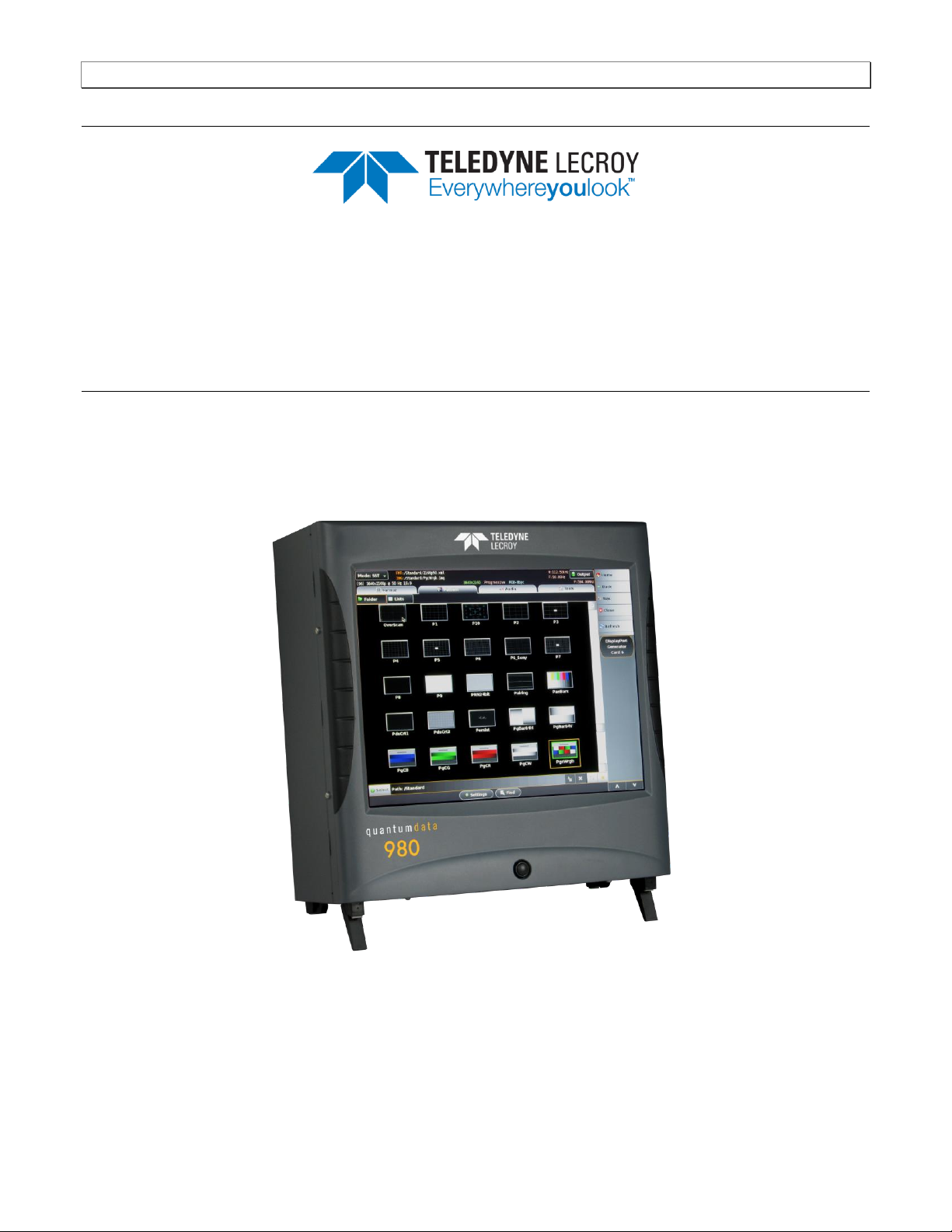
980 DP1.4 Video Generator / Analyzer Module
User Guide
Rev: A1
Page 1 June 16, 2017

980 DP 1.4 Video Generator / Analyzer - User Guide Rev. A1
Table of Contents
1 About the 980 DP 1.4 Video Generator / Analyzer Module 9
1.1 Scope of this User Guide 9
1.2 Changes to this User Guide 10
1.3 What options are available with the 980? 10
1.4 980 User Interface 14
2 Getting Started 15
2.1 What is shipped with the 980 DP Video Generator / Analyzer module? 15
2.2 Operational workflow for DP Video Pattern Testing 15
3 Testing DP Displays with the 980 DP Video Generator / Analyzer module 17
3.1 Workflow for running the video pattern testing of DP displays 17
3.2 Connector Description 18
3.3 Making the physical DP connections 20
3.4 Navigating through the 980 GUI Manager interface 21
3.5 Selecting DP formats 26
3.6 Selecting formats (resolutions) 28
3.7 Configuring the format Settings 37
3.8 Selecting Test Patterns 39
3.9 Selecting Test Patterns Settings 43
3.10 Testing audio on an audio rendering device 46
3.11 Viewing the EDID of a connected display 49
3.12 Viewing the DPCD of a connected display 53
3.13 Testing HDCP on a connected display 65
4 HDCP 2.2 Tests 70
4.1 Running an HDCP 2.2 source test 70
4.2 Running an HDCP 2.2 Sink test 74
4.3 Viewing the HDCP 2.2 authentication transaction using the Auxiliary Channel Analyzer (ACA) utility 83
5 DP Link Training Control 84
5.1 Accessing the Link Training Control application 84
6 DP Multi-Stream Transport (MST) Testing 92
6.1 Accessing the MST Topology window 92
6.2 Configuring the number of downstream MST nodes. 96
6.3 Reading the EDID of a downstream MST node. 98
6.4 Reading the DPCD of a downstream MST node. 100
6.5 View the MST transactions on the Auxiliary Channel Analyzer (ACA). 103
7 Auxiliary Channel Analyzer (ACA) Utilities 105
7.1 Aux Channel Analyzer (ACA) – For Real Time Viewing of Auxiliary Channel Data 105
7.2 ACA Remote Control – For Real Time Viewing of DisplayPort Aux Channel Data 112
7.3 Monitoring the Auxiliary Channels with the Aux Channel Analyzer utilities 116
7.4 ACA Data Viewer – Viewing Stored Aux Channel Data 127
7.5 Viewing Stored DP Aux Chan traces on a PC with the ACA Data Viewer utility 132
7.6 Using the ACA Find Feature 138
7.7 Using the ACA Filter Feature 149
Page 2 June 16, 2017

980 DP 1.4 Video Generator / Analyzer - User Guide Rev. A1
8 Pattern List Editor 164
8.1 Creating a custom list of test patterns 164
8.2 Applying a custom Pattern List 170
8.3 Viewing a custom Pattern List 176
8.4 Opening a custom Patten List from the Pattern List Editor 179
9 Format List Editor 181
9.1 Opening a custom Format List 181
9.2 Applying a custom Format List 188
9.3 Viewing a custom Format List 190
9.4 Opening a custom Format List 191
10 Format Editor 193
10.1 Accessing the Format Editor 193
10.1 Format Editor - Basic Window Configuration and Operation 196
10.2 Format Editor – New Format 198
10.3 New Format - Digital Video Tab 208
10.4 New
10.5 New Format - AFD Tab 212
10.6 Format Editor - Open 214
10.7 Format Editor - Save 215
10.8 Creating a new format using the Format Editor 216
10.9 Modifying an existing format using the Format Editor 220
11 Source Verification with Basic Analyzer (Optional) 223
11.1 Accessing the Basic Analyzer features 223
11.1 226
11.2 Network Analyzer Dashboard 226
11.3 Main Control Panel 227
11.4 Connecting a DisplayPort source to the Rx Analyzer port 228
11.5 Controlling the Network Analyzer 229
11.6 Emulating an MST Rx port 238
11.7 DPCD Editor 242
12 Source Verification with Protocol Analyzer (Optional) 252
12.1 Operational workflow for capturing data with your 980 DP Protocol Analyzer 252
12.2 Opening an Existing Capture 252
12.3 Capture Control Panel 254
12.4 Configuring the 980 DP Protocol Analyzer with an EDID 258
12.5 Connecting a DisplayPort source to the Rx Analyzer port 261
12.6 Verifying source video 262
12.7 Capturing DisplayPort source data 263
12.8 Capture Viewer Panels 268
12.9 Event Plot Panel 269
12.10 Data Decode Panel 276
12.11 Link Symbol Panel 278
12.12 Searching and Filtering for Specific Data Elements 279
12.13 Filtering Specific Data Elements 287
Format -
Digital Audio Tab 210
Page 3 June 16, 2017

980 DP 1.4 Video Generator / Analyzer - User Guide Rev. A1
12.14 Importing and Exporting Capture files 291
14 Command Reference 296
15.1 Accessing the Command Line 296
15.2 Command Line Conventions 299
14.1 Video-Related commands 300
14.2 Audio Generation-Related commands 303
14.3 Analyzer-Related commands 305
15 Upgrading the 980 Manager and 980 307
16 Image Reference 309
16.1 Standard image descriptions 309
16.2 3DXTalk 309
16.3
16.4
16.5
16.6 Acer7 and Acer8 313
16.7 Acer9 314
16.8 AFDtest 315
16.9 Anamorph 316
16.10 AnsiGray 317
16.11 AnsiLght 318
16.12 Apple 1 319
16.13 Audio_L, Audio_Lf, Audio_R, Audio_Rf, Audio_X, Audio_Xf 320
16.14 Audio_1, Audio_1f, Audio_2, Audio_2f, Audio_3, Audio_3f, Audio_4, Audio_4f, Audio_5, Audio_5f ,
Audio_6, Audio_6f, Audio_7, Audio_7f, Audio_8, Audio_8f 321
16.15 BarBlack 322
16.16 BLU_EM, GRN_EM, RED_EM, WHT_EM,
MESony_R 323
16.17 BLU_EM+, GRN_EM+, RED_EM+, WHT_EM+, MEMEPlus, MEPlus_B, MEPlus_G, and MEPlus_R 324
16.18 BLU_PIC, GRAY_PIC, GRN_PIC, RED_PIC, WHT_PIC 325
16.19 Bosch 327
16.20 Box_50mm, Box_64mm, Box100mm, Box150mm, Box200mm, Box250mm 328
16.21 BriteBox 329
16.22 Burst (TV formats only) 330
16.23 BurstTCE 331
16.24 CECTest1, CECTest2 332
16.25 Check511 333
16.26 CheckBy3 334
16.27 CheckBy6 335
16.28 Check_02 336
16.29 Check_11 337
16.30 Checkers 338
16.31 CirclesL 339
16.32 CirclesS 340
16.33 ColorBar 341
Acer1
310
Acer2
311
Acer3, Acer4, Acer5, Acer6
312
MEME1111, MEMESony,
MESony_B, MESony_G, and
Page 4 June 16, 2017

980 DP 1.4 Video Generator / Analyzer - User Guide Rev. A1
16.34 ComFocus 342
16.35 Crosshtch 343
16.36 Cubes 344
16.37
16.38
16.39
16.40 Diamond1 348
16.41 Dot1606, Dot1610, Dot1612, Dot1615, Dot1812, Dot1815, Dot2016 349
16.42 DOT_10,DOT_12,DOT24 350
16.43 DV_Swing, DVSwing2 352
16.44 Dyna 353
16.45 EdidData, Edid2 354
16.46 EdidHdmi1, EdidHdmi2 355
16.47 Elbit 356
16.48 EMITest1 , EMITest3 , EMITest3 , EMITest4 , EMITest5 357
16.49 Examples 359
16.50 Flat, Flat07, Flat13, Flat20, Flat27, Flat33, Flat40, Flat47, Flat53, Flat60, Flat67, Flat73, Flat80, Flat87,
Flat93, FlatGray, Flat_01, Flat_02, Flat_03, Flat_04, Flat_05, Flat_06, Flat_07, Flat_08, Flat_09, Flat_10, Flat_11,
Flat_12, Flat_13, Flat_14, Flat_15, Flat_16 360
16.51 Flat_B, Flat_G, Flat_R 361
16.52 FlashRGB 362
16.53 Focus20 363
16.54 FocusC14 364
16.55 FocusCCx 365
16.56 FocusEM 366
16.57 FocusEMP 367
16.58 FocusM00 - FocusM15 368
16.59 Focus_@6, Focus_@7, Focus_@8, Focus_@ 369
16.60 Focus_Cx 370
16.61 Focus_H 371
16.62 Focus_MM 372
16.63 Focus_Oo 373
16.64 FontViewer 374
16.65 Format 375
16.66 Geom_1 – Geom_5 376
16.67 Gray25, Gray40 377
16.68 GrayBar 378
16.69 GrayL1, GrayL3 379
16.70 Grays5, Grays9, Grays11, Grays16, Grays32, Grays64 380
16.71 GraysAll 381
16.72 GraysMHL 382
16.73 Gray_PIC 383
16.74 Grill_11, Grill_15, Grill_22, Grill_33,
16.75 GRN_EM, GRM_EM+, GRN_HTCH, GRN_PIC 385
CUBES3D
DecodAdj
DecodChk
345
346
347
Grill_44
384
Page 5 June 16, 2017

980 DP 1.4 Video Generator / Analyzer - User Guide Rev. A1
16.76 H_Stair 386
16.77 HalfArea 387
16.78 HalfClk 388
16.79 Hat1606, Hat1610, Hat1612, Hat1615 389
16.80 Hat1606A, Hat1610A, Hat1612A, Hat1615A 390
16.81 Hat1812, Hat1815 391
16.82 Hat1812A, Hat1815A 392
16.83 Hat2016 393
16.84 Hat2016A 394
16.85 Hatch_6, Hatch_10i, Hatch_10o, Hatch_12i, Hatch_12o, Hatch_24i, Hatch_24o, Hatch_24s, Hatch_G,
Hatch_M, GRN_HTCH, and MAGENTA 395
16.86 Hatch_16, Hatch_20 397
16.87 Hatch20 398
16.88 Hatch4x3, Hatch5x4 and Hatch8x8 399
16.89 Hatch64W 400
16.90 HdcpProd, Hdcp2 401
16.91 Hitatchi 402
16.92 HiLoTrk 403
16.93 HSVnRGB 404
16.94 Imex1 405
16.95 InFocus1 406
16.96 InFocus2 407
16.97 KanjiKAN 408
16.98 L80 409
16.99 LGLCDTVB, LGLCDTVG, LGLCDTVR, LGLCDTVW 410
16.100 LGRamp 411
16.101 Linearty (Linearity) 412
16.102 LinFocus 414
16.103 LipSync, LipSyncB 416
16.104 MAGENTA 417
16.105 Master 418
16.106 MESony_R, MESony_G, MESony_B, 419
16.107 MEMEPlus, MEPlus_B, MEPlus_G, and MEPlus_R 420
16.108 MnslCLR 421
16.109 MnslGM 422
16.110 MnslPG 423
16.111 MoireX, MoireX33, MoireY, MoireY33 424
16.112 Monoscope 425
16.113 MSony7, MSony8 426
16.114 MulBurst 427
16.115 Needle 428
16.116 Orion 429
16.117 Outline0, Outline1, Outline2, Outline3 430
16.118 OverScan 435
Page 6 June 16, 2017

980 DP 1.4 Video Generator / Analyzer - User Guide Rev. A1
16.119 P1 436
16.120 P2 437
16.121 P3 438
16.122 P4 439
16.123 P5 440
16.124 P6 441
16.125 P6_Sony 442
16.126 P7 443
16.127 P8 444
16.128 P9 445
16.129 PacketTx 446
16.130 Pairing 447
16.131 PanBars 448
16.132 PdsCrt1 448
16.133 PdsCrt2 449
16.134 Persist 450
16.135 PgBar64H, PgBar64V 452
16.136 PgCB, PgCG, PgCR, PgCW, PgCWrgb 453
16.137 Philips1 454
16.138 Pluge 455
16.139 PRN24bit 456
16.140 PulseBar 457
16.141 QuartBox 458
16.142 Ramp 460
16.143 Ramp12 461
16.144 RampDif 462
16.145 RampX 463
16.146 Ramp_B, Ramp_G, and Ramp_R 464
16.147 Raster 465
16.148 RED_EM, RED_EM+ 466
16.149 Regulate 467
16.150 Samsung1, Samsung2 468
16.151 Samsung3 469
16.152 Samsung 4 470
16.153 Samsung5 471
16.154 Samsung6 472
16.155 SansungB 473
16.156 SamsungT 474
16.157 Set01k 475
16.158 Sharpnes 476
16.159 SlideBox 477
16.160 SMPTE133 478
16.161 SMPTEbar, SMPTEbr2 482
16.162 Sony6 485
Page 7 June 16, 2017

980 DP 1.4 Video Generator / Analyzer - User Guide Rev. A1
16.163 Sony6WLC 486
16.164 sRGBflat 487
16.165 Staircase 488
16.166 Strokes0, Strokes1 489
16.167 TAARamp 490
16.168 Taffeta 491
16.169 Text_9, Text_9T, Text_11, Text_12T, Text_16 492
16.170 TextFlat 493
16.171 ThreeBar 494
16.172 TintAlign 495
16.173 Toshiba 496
16.174 TPVAOC1 and TPVAOC2 497
16.175 TTECorp1 498
16.176 TVBar100 & TVBar_75 (TV formats only) 499
16.177 TVBarH 502
16.178 TVHatch 503
16.179 TVoutLin 504
16.180 TVSplBar 505
16.181 WHT_EM, WHT_EM+ 506
16.182 ZonePlt 507
Page 8 June 16, 2017
980 DP 1.4 Video Generator / Analyzer - User Guide Rev. A1
1 About the 980 DP 1.4 Video Generator / Analyzer Module
This chapter provides an overview of features of the 980 DP 1.4 Video Generator / Analyzer module and the 980
GUI Manager. The module can be equipped in either of the following 980 Advanced Test Platforms:
1) The 980B Advanced Test Platform – 5-slot chassis with a 15 inch touch display
2) The 980R Advanced Test Platform - 5-slot rack mountable chassis with a 7 inch touch display
The 980 DP 1.4 Video Generator / Analyzer module supports video pattern testing and audio testing of DP 1.4
capable displays at 8.1Gb/s link rates per 4 lanes. It is equipped with two (2) Tx ports and an Rx port. The two DP
Tx ports are both active simultaneously which enables you to test multiple sinks and displays at the same time. The
Rx port is for the optional DP analyzer for testing DisplayPort source devices up to 8.1Gb/s link rates per 4 lanes.
The 980 GUI Manager is a PC application to manage and use the 980 DP Video Generator / Analyzer module.
1.1 Scope of this User Guide
This User Guide provides descriptive and procedural information on the 980 DP 1.4 Video Generator / Analyzer
module for testing DP display devices.
Although you can operate the 980 DP 1.4 Video Generator / Analyzer module through the “embedded GUI,” most
of the examples used in the procedures in this User Guide are taken from the external standalone PC 980 GUI
Manager. The procedures are nearly identical between the embedded GUI running through the 980B/980R front
panel display and the external standalone PC application but the look and feel is slightly different.
There are separate User Guides for the other 980B/980R modules. The following is a list of the User Guides
available with the 980B/980R and its modules. These are available from the downloads and product web pages of
the Quantum Data website http://www.quantumdata.com/products/980.asp:
The following is a list of the User Guides available for the 980 systems:
980 HDMI Protocol Analyzer Gen 3 System – Covers source analysis testing for HDMI and MHL source
devices as well as various transmitter features. This user guide is specifically for the functions of the 980 HDMI
Protocol Analyzer Gen 3 system sold through 2012.
980 HDMI Protocol Analyzer module – Covers source analysis features of the 980 HDMI Protocol Analyzer
module. Used in conjunction with the 980 Advanced Test Platform Quick Start Guide for purchases in 2013.
980 Advanced Test Platform Quick Start Guide – Covers startup procedures for the 980/980B platform. Used
in conjunction with the 980 HDMI Protocol Analyzer Module User Guide for purchases in 2013.
Page 9 June 16, 2017

980 DP 1.4 Video Generator / Analyzer - User Guide Rev. A1
980 HDMI Protocol Analyzer module – Covers source analysis testing for HDMI and MHL source devices as
well as various transmitter features. This user guide is specifically for the functions of the 980 HDMI Protocol
Analyzer module equipped in one of the 980 Advanced Test Platform slots (980 Gen 3 or 980B). Used in
conjunction with the 980 Advanced Test Platform Quick Start Guide.
980 HDMI Protocol Analyzer HDMI/MHL Source Compliance Test – Covers source compliance testing for both
MHL and HDMI sources. These compliance test applications are provided by the 980 HDMI Protocol Analyzer
module or the 980 HDMI Protocol Analyzer Gen 3 system. Used in conjunction with the 980 Advanced Test
Platform Quick Start Guide.
980 HDMI Protocol Analyzer HDMI/MHL Sink Compliance Test – Covers sink compliance testing for both MHL
and HDMI sinks (and MHL dongles). These compliance test applications are provided by the 980 HDMI
Protocol Analyzer module or the 980 HDMI Protocol Analyzer Gen 3 system. Used in conjunction with the 980
Advanced Test Platform Quick Start Guide.
980 MHL CBUS Compliance Test Module - Covers MHL CBUS compliance testing for both MHL sources as
well as sinks and dongles. This compliance test applications are provided by the 980 CBUS Compliance Test
module. Used in conjunction with the 980 Advanced Test Platform Quick Start Guide.
980 HDMI Video Generator module – Covers the features and functions offered by the 980 HDMI Video
Generator module. Used in conjunction with the 980 Advanced Test Platform Quick Start Guide.
980 HDMI 2.0 Video Generator module – Covers the features and functions offered by the 980 HDMI 2.0 Video
Generator module. Used in conjunction with the 980 Advanced Test Platform Quick Start Guide.
980 HDMI 2.0 Protocol Analyzer module – Covers source analysis features of the 980 HDMI 2.0 Protocol
Analyzer module. Used in conjunction with the 980 Advanced Test Platform Quick Start Guide.
980 DP Video Generator module – Covers the features and functions offered by the 980 DP Video Generator
module. Used in conjunction with the 980 Advanced Test Platform Quick Start Guide.
980 DP 1.4 Video Generator module (This User Guide) – Covers the features and functions offered by the 980
DP Video Generator module. Used in conjunction with the 980 Advanced Test Platform Quick Start Guide.
1.2 Changes to this User Guide
This is a new User Guide
Note: Please be sure to check the Quantum Data website for updates to this User Guide.
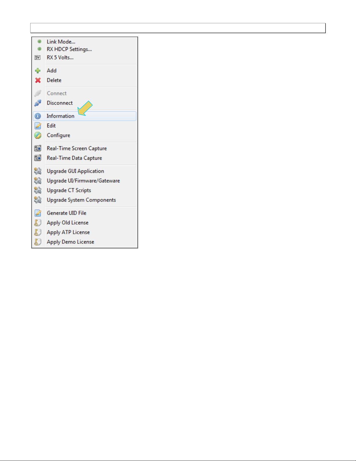
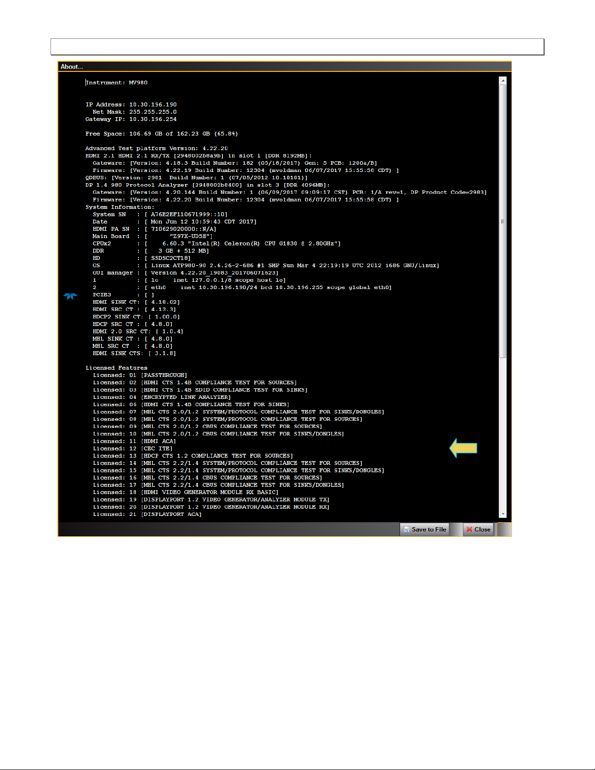
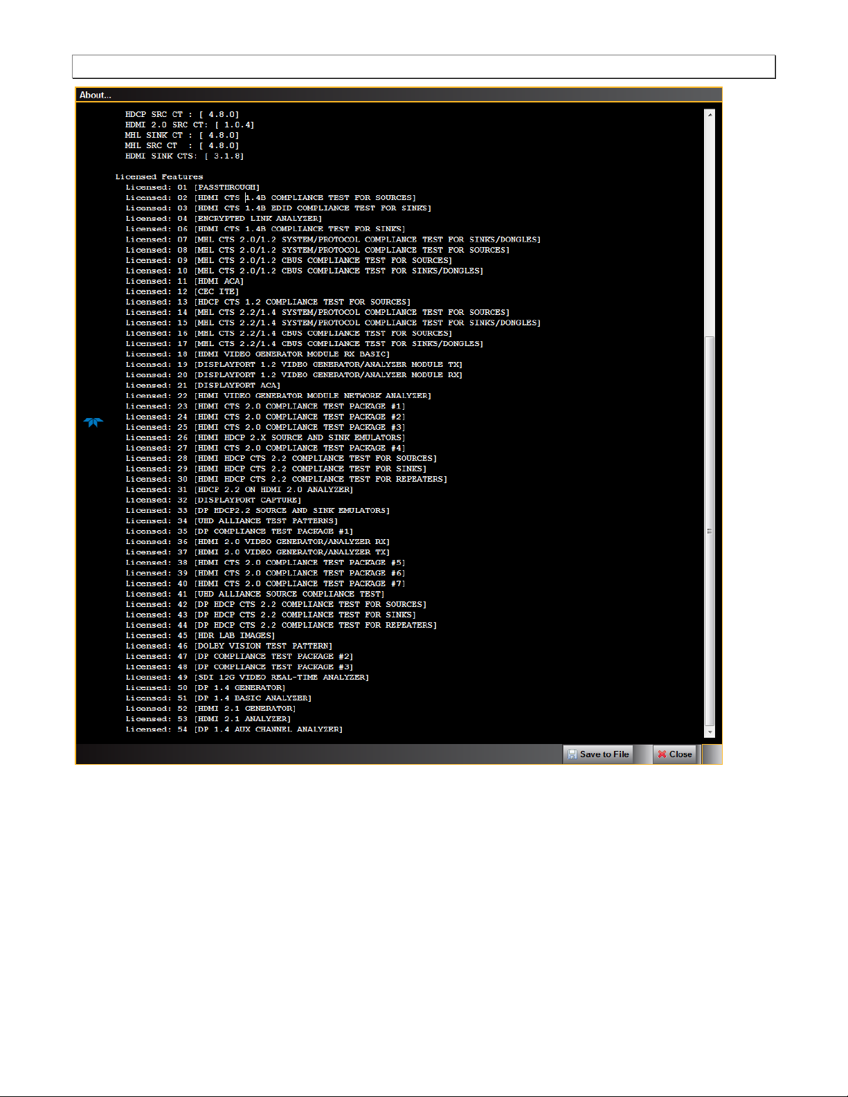
1.3 What options are available with the 980?
You can determine what options the 980 DP 1.4 Video Generator / Analyzer is equipped with by accessing the
Instrument Information screen on either the built-in or external 980 GUI manager. When using the external 980
GUI Manager you must be connected to the 980B/980R in order to read the Instrument Information.
Page 10 June 16, 2017
980 DP 1.4 Video Generator / Analyzer - User Guide Rev. A1
Page 11 June 16, 2017
980 DP 1.4 Video Generator / Analyzer - User Guide Rev. A1
Page 12 June 16, 2017
980 DP 1.4 Video Generator / Analyzer - User Guide Rev. A1
Page 13 June 16, 2017
980 DP 1.4 Video Generator / Analyzer - User Guide Rev. A1
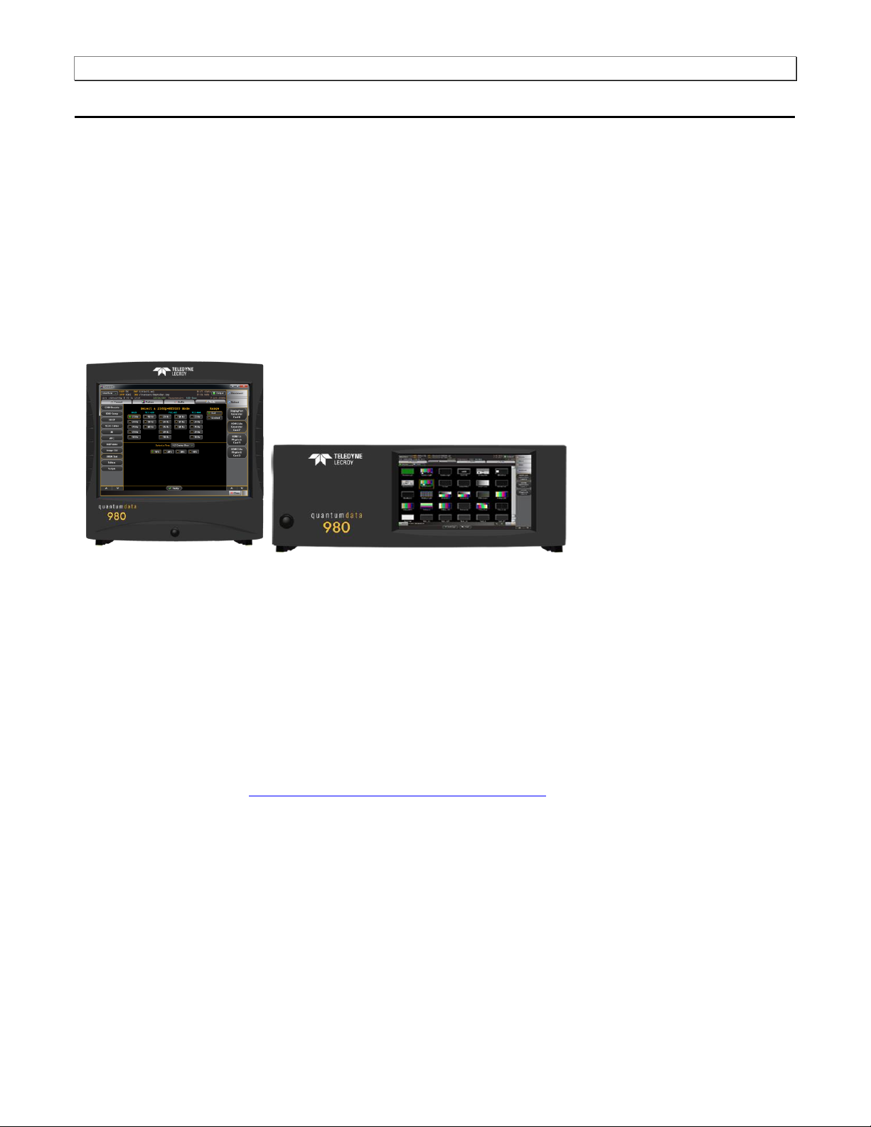
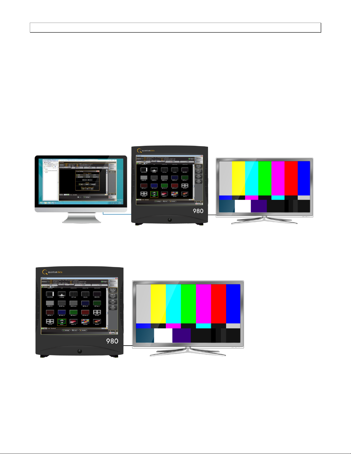
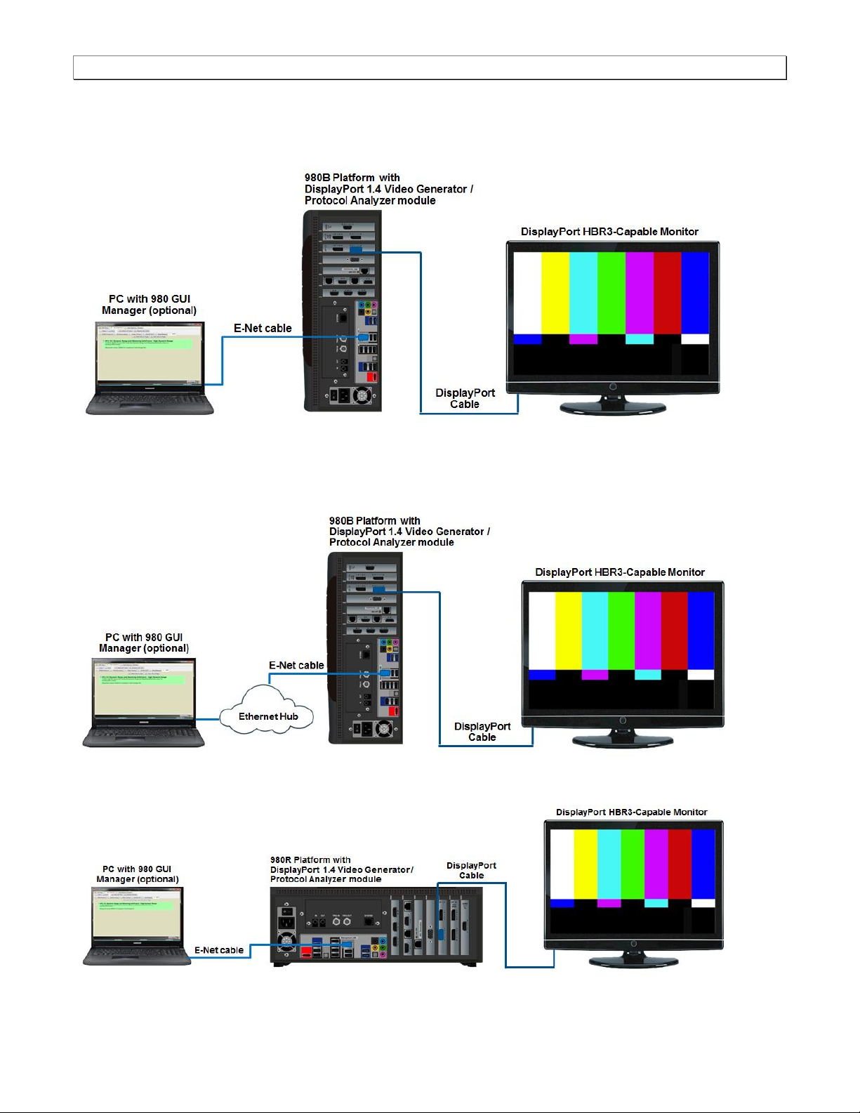
1.4 980 User Interface
The 980B/980R provide a graphical user interface for operation. This GUI can run both on the 980B/980R through
the built-in color touch screen display or as a standalone application running on a PC. The look and feel and
functions are similar but not identical. The first illustration below shows a PC (left) connected to the 980B through
an Ethernet cable for operation through the external 980 GUI Manager. The second illustration depicts the
embedded 980 GUI Manager.
1.4.1 External 980 GUI Manager
The external 980B GUI Manager provides convenient operation of the 980 DP 1.4 Video Generator module from
your PC. The larger screen size on the external 980 GUI Manager enables you to use multiple panels at the same
time.
1.4.2 Embedded 980 GUI Manager
You can operate the 980B/980R fully through the built-in color touch screen display.
Page 14 June 16, 2017

980 DP 1.4 Video Generator / Analyzer - User Guide Rev. A1
2 Getting Started
This chapter explains what is involved in getting your 980B/980R system up and operating to capture data.
2.1 What is shipped with the 980 DP Video Generator / Analyzer module?
The 980 DP 1.4 Video Generator / Analyzer module can optionally be equipped in the 980B/980R Advanced Test
Platforms. The following items are included with the 980 DP Video Generator / Analyzer module:
DP cable (P/N 30-00162) – used for connecting to the 980 DP 1.4 Video Generator / Analyzer module to the
device under test.
2.2 Operational workflow for DP Video Pattern Testing
The following are the high level steps you will need to follow to get your 980 DP 1.4 Video Generator / Analyzer
module up and running.
2.2.1 Procedures covered in 980 Advanced Test Platform Quick Start Guide:
The following list of activities are described in the 980 Quick Start Guide.
1. Remove the 980B/980R from the shipping box.
2. Assemble the source device under test into your lab area and power it up.
3. Connect the 980B/980R power cable (provided) to a suitable outlet (110-240V 50/60Hz) and apply power to
the 980.
4. (Optional – not required if using the built-in display) Select a suitable PC to host the 980 GUI Manager
application. A minimum of 512MB of RAM is recommended. (Note that you do not need a PC because you can
use the built-in Front Panel display; however the external 980 GUI Manager provides you with a larger viewing
area).
5. (Optional – not required if using the built-in display) Determine how you are going to connect to the 980/980B
from the external 980 GUI Manager in order to operate the instrument:
o Put the 980B/980R on your corporate network and enable DHCP using an available Ethernet patch cable,
or…
o Connect directly with a host PC or laptop using the Ethernet crossover cable provided.
6. (Optional – not required if using the built-in display) Assign an IP address to the 980B/980R either directly or by
enabling DHCP.
7. (Optional – not required if using the built-in display) Download the latest 980 GUI Manager application from the
Quantum Data website:
www.quantumdata.com/downloads/index.asp.
8. (Optional – not required if using the built-in display) Install the 980 Manager application on your host PC.
9. (Optional – not required if using the built-in display) Establish a connection to the 980B/980R from the 980
Manager resident on your host PC.
10. (Optional – not required if using the built-in display) Through the 980 Manager “Add” the 980B/980R as an
Instrument.
2.2.2 Procedures covered in this User Guide:
1. Connect the sink device under test to the DP Tx port on the 980 DP Video Generator / Analyzer module.
Page 15 June 16, 2017

980 DP 1.4 Video Generator / Analyzer - User Guide Rev. A1
2. Selecting video formats (resolutions).
3. Setting the colorimetry and video mode.
4. Selecting the test patterns.
5. Running other tests on DP sink devices.
Page 16 June 16, 2017

980 DP 1.4 Video Generator / Analyzer - User Guide Rev. A1
3 Testing DP Displays with the 980 DP Video Generator / Analyzer module
This chapter describes how to operate the 980 DP 1.4 Video Generator / Analyzer module to test DP display
devices (HDTVs, PC monitors).
3.1 Workflow for running the video pattern testing of DP displays
The workflow below is a high level set of tasks for operating the 980 DP Video Generator / Analyzer module. Note
that the installation of the external 980 GUI Manager and the Ethernet session are optional; you can run the tests
through the embedded GUI Manager.
1. Power up the 980. Refer to the procedures in Powering up the 980.
Note: The power switch in the front is used when you are turning off the 980 for a short period of time. For
extended periods of off time, it is best to power the 980 down by first using the power button on the front and
then the rocker switch on the back.
2. (Optional) Establish an Ethernet/IP connection between the external 980 GUI Manager and the 980B/980R
Advanced Test Platform using the procedures in the 980 Advanced Test Platform Quick Start Guide.
3. Connect the DP sink device under test to one of the module’s Tx ports.
4. Access the module’s interface through the 980 GUI Manager.
5. Select DP.
6. Select the formats (timing or resolution).
7. Select the test patterns you wish to test with.
8. Select any video options and settings.
9. Select the audio format.
10. Monitor the sink DUT for any anomalies.
Page 17 June 16, 2017
980 DP 1.4 Video Generator / Analyzer - User Guide Rev. A1
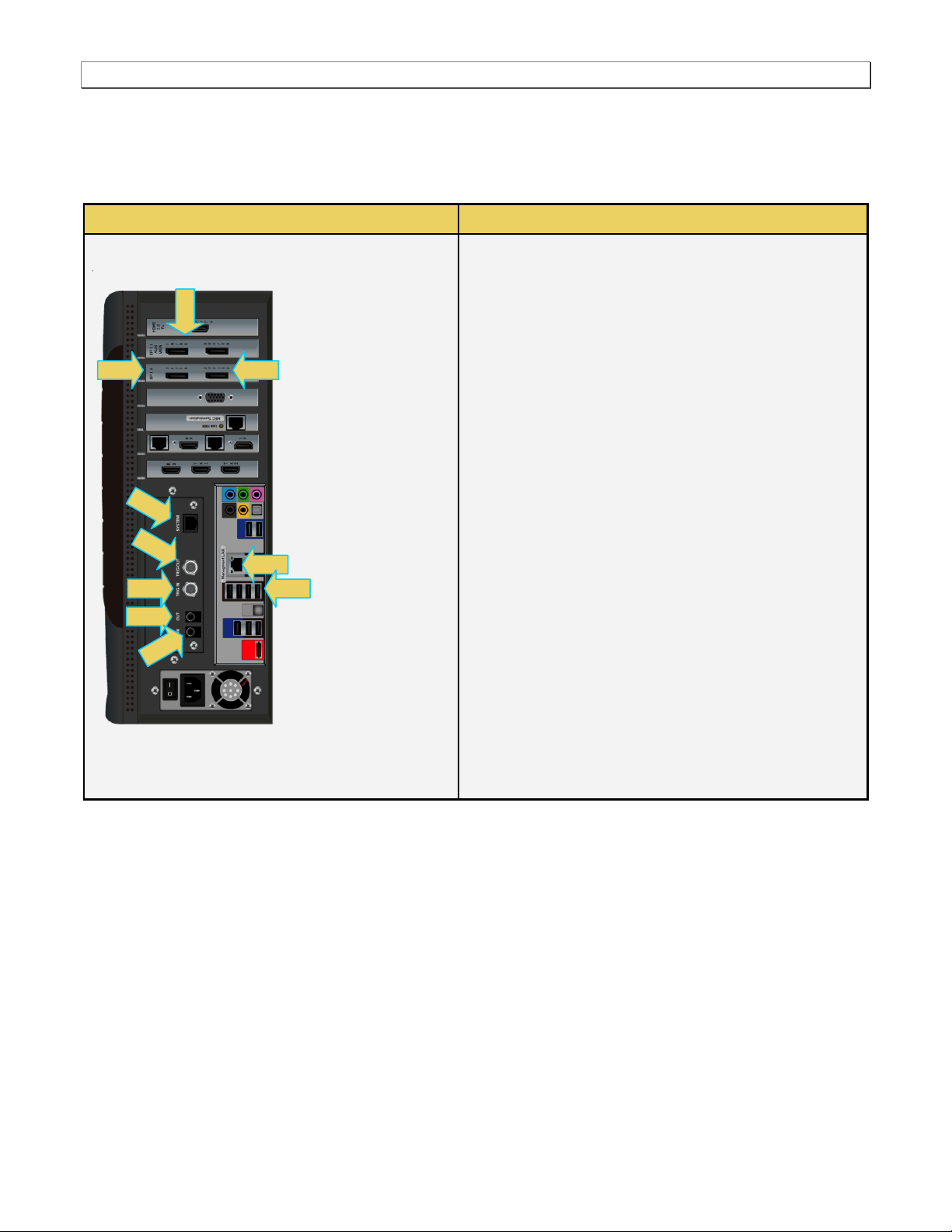
980 Configurations
Information / Function
DP Video Generator module – 980B
The following is a description of each connector:
980 DP Video Generator / Analyzer module:
A – DP Rx port for analyzing DP sources.
B – DP Tx1 port for DP video/audio generation.
C – DP Aux Passive Monitoring module Tx and Rx
for passively monitoring the DP Aux Chan between a
source and a display.
Note: This feature is not currently functional.
980B QD Bus Board:
D – Internal Ethernet Tx connector; not used.
E – BNC Trig OUT connector. Not used for this
module.
F – BNC Trig IN connector. Not used for this module.
G – RCA OUT connector for SPDIF function. Not
used for this module.
H – RCA IN connector for SPDIF function. Not used
for this module.
980B Lower Panel:
I – Ethernet port for connection to PC host for 980
GUI Manager application, telnet for command line
control and FTP for transferring files.
J – Various USB ports for transferring files and
restoring system.
C
3.2 Connector Description
Use the following table to identify the connector function and descriptions on your 980 DP 1.4 Video Generator
module.
Page 18 June 16, 2017
980 DP 1.4 Video Generator / Analyzer - User Guide Rev. A1
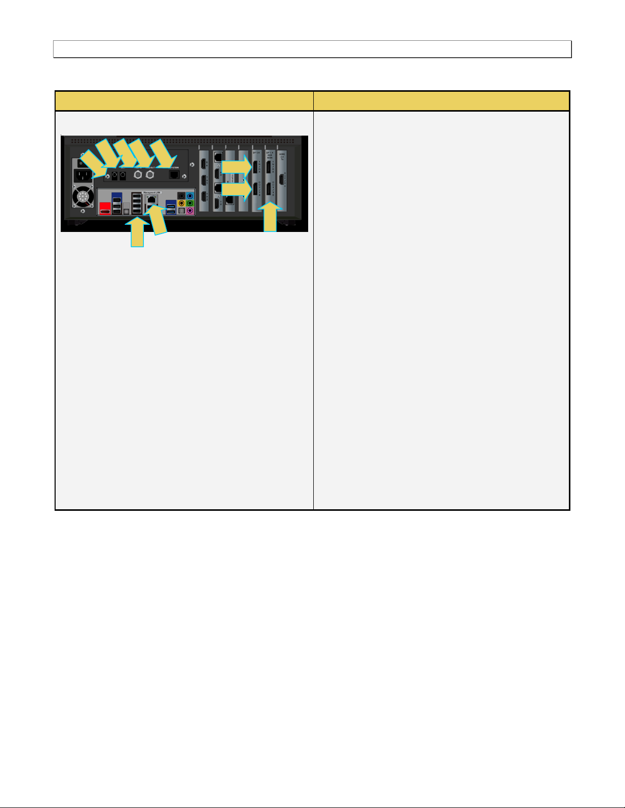
980B Configurations
Information / Function
DP Video Generator module – 980R
The following is a description of each connector:
980 DP Video Generator / Analyzer module:
A – DP Rx port for analyzing DP sources.
B – DP Tx1 port for DP video/audio generation.
C – DP Aux Passive Monitoring module Tx and Rx
for passively monitoring the DP Aux Chan
between a source and a display.
Note: This feature is not currently functional.
980B QD Bus Board:
D – Internal Ethernet Tx connector; not used.
E – BNC Trig OUT connector. Not used for this
module.
F – BNC Trig IN connector. Not used for this
module.
G – RCA OUT connector for SPDIF function. Not
used for this module.
H – RCA IN connector for SPDIF function. Not
used for this module.
980B Lower Panel:
I – Ethernet port for connection to PC host for 980
GUI Manager application, telnet for command line
control and FTP for transferring files.
J – Various USB ports for transferring files and
restoring system.J – Various USB ports for
transferring files and restoring system.
I J D H F E G
C
Use the following table to identify the connector function and descriptions on your 980R system configuration.
Page 19 June 16, 2017
980 DP 1.4 Video Generator / Analyzer - User Guide Rev. A1
3.3 Making the physical DP connections
This subsection describes the physical DP connections required to run the video pattern tests on a DP display.
Connection for video testing – 980B Direct Connection (Side View)
Connection for video testing – 980B Ethernet hub or corporate LAN example (Side View)
Page 20 June 16, 2017
980 DP 1.4 Video Generator / Analyzer - User Guide Rev. A1
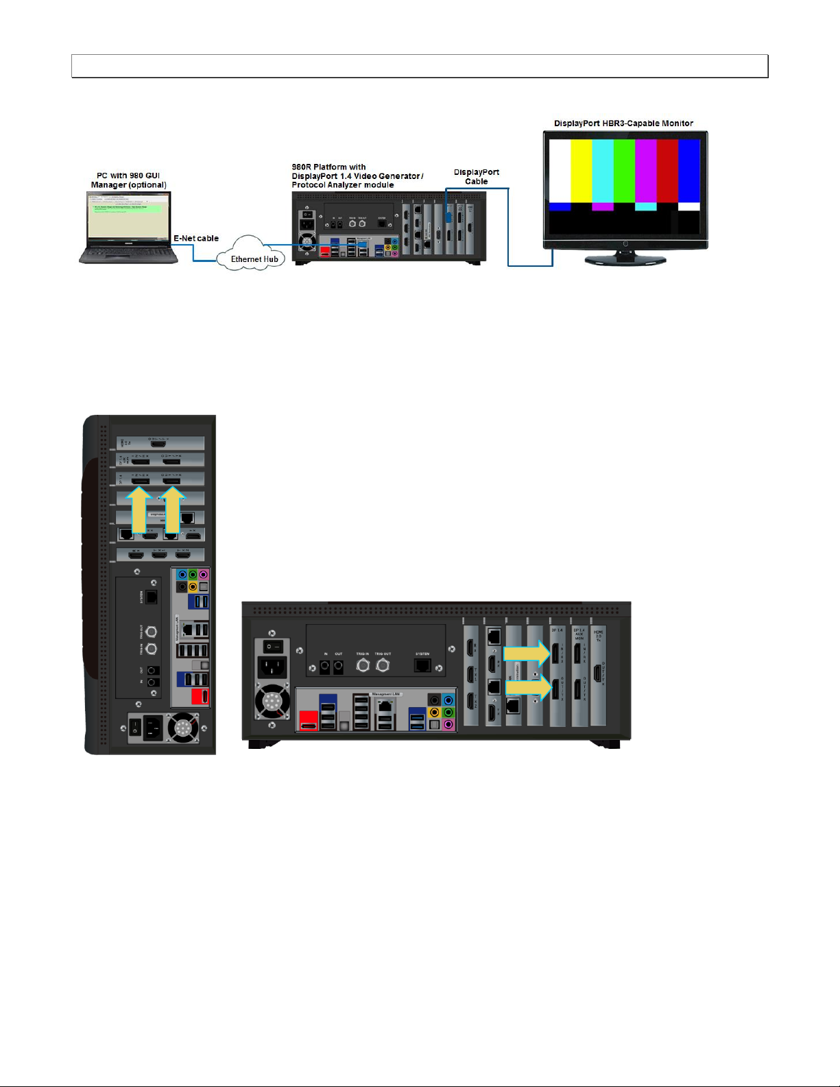
Connection for video testing – 980R Direct Connection (Rear View)
Connection for video testing – 980R Ethernet hub or corporate LAN example (Rear View)
To make the physical DP connections:
This procedure assumes that you have assembled the 980B/980R with the 980 DP 1.4 Video Generator / Analyzer
module and the DP display device under test and applied power to all these devices. Refer to the procedures
below and the diagram above.
1. Connect your DP display device under test to one of the DP Tx connectors on the 980 DP Video Generator /
Analyzer module. Use a DP-compliant cable.
Note: The DP Video Generator module can be installed in either slot 3 (shown) or slot 6 of the 980B and slot 1,
3 or 6 in the 980R.
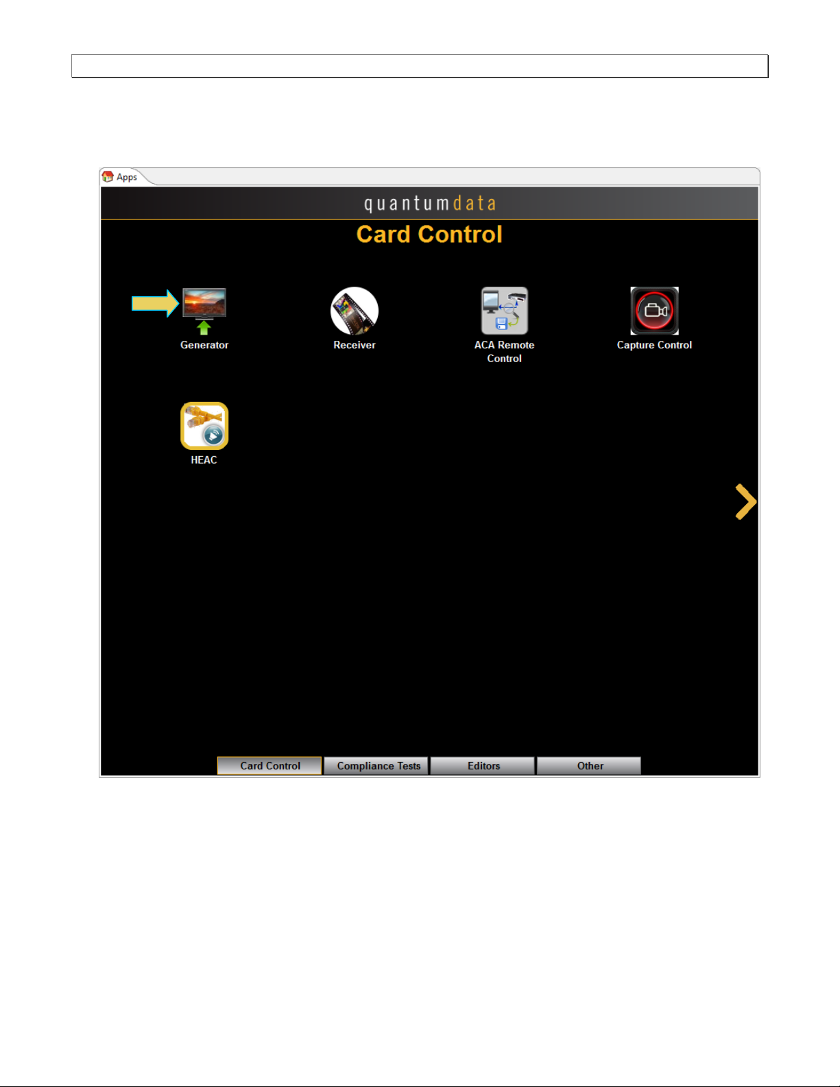
3.4 Navigating through the 980 GUI Manager interface
Use the following procedures to navigate to the 980 DP 1.4 Video Generator / Analyzer module testing functions.
You can access the 980 DP 1.4 Video Generator / Analyzer module functionality through the Card Control tab
(Page 1 of 4) of the Apps panel. Use the procedures provided below.
Page 21 June 16, 2017
980 DP 1.4 Video Generator / Analyzer - User Guide Rev. A1
To navigate to the video test functions:
1. From the View menu, enable select the Generator item.
Page 22 June 16, 2017
980 DP 1.4 Video Generator / Analyzer - User Guide Rev. A1
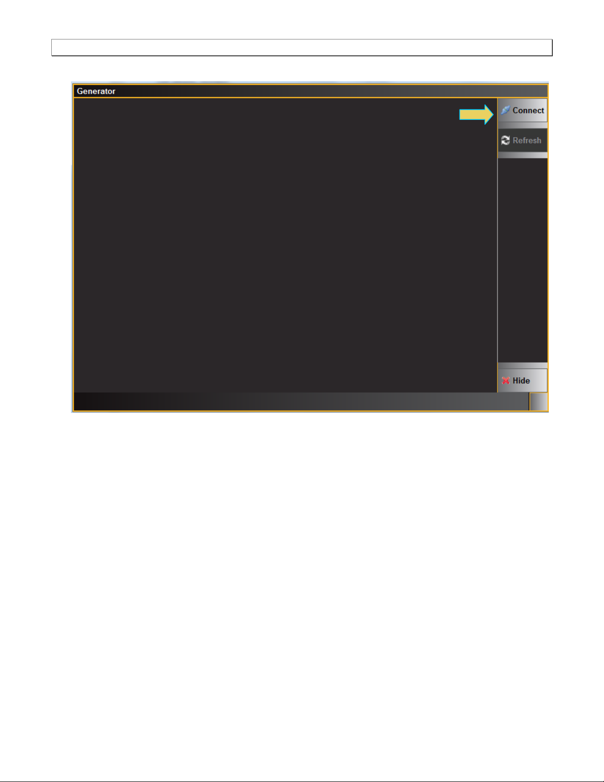
A blank Generator panel appears as shown below asking you to connect to the 980B/980R.
2. Click on the Connect button to initiate a connection between the 980 GUI Manager and the 980 Generator
application.
Once you establish the connection, the Generator panel will be populated as shown below:
Page 23 June 16, 2017
980 DP 1.4 Video Generator / Analyzer - User Guide Rev. A1
Generator Status Area (Top)
There are a set of port selector/indicator buttons on the right side of the panel (indicated below). The module
will be in one of slots 1 through 7 on the 980B/980R.
The Generator screen has a status area on the top of its panel. The status area provides the following
information:
Page 24 June 16, 2017
980 DP 1.4 Video Generator / Analyzer - User Guide Rev. A1
Item
Description
Port
Active port, in this case the two Tx connectors (T30 and T31).
INTF
The currently selected interface type for the module. This could be either, DP, HDMI or
DVI. The sampling mode is included in parentheses after the interface.
FMT
The currently active format (selected resolution) and its directory path.
IMG
The currently active image (selected test pattern) and its directory path.
Video Identification Code (VIC)
The VIC code is shown on the lower left of the upper status panel
Resolution, scan and color
The resolution, scan and colorimetry type are shown on in the lower portion of the
upper status panel in the center.
H:(Rate)
The horizontal refresh rate of the selected timing.
F:(Rate)
The frame or vertical refresh rate of the selected timing.
P:(Pixel Rate)
The pixel clock rate of the selected timing.
Please note that if you are also making changes through the command line the information in the status area is
not automatically updated. You must click on the Refresh activation button to re-sync the status
area.
Page 25 June 16, 2017
980 DP 1.4 Video Generator / Analyzer - User Guide Rev. A1
3.5 Selecting DP formats
Use the following procedures to select the mode, DP, in the 980 DP 1.4 Video Generator / Analyzer module.
To select interface (DP):
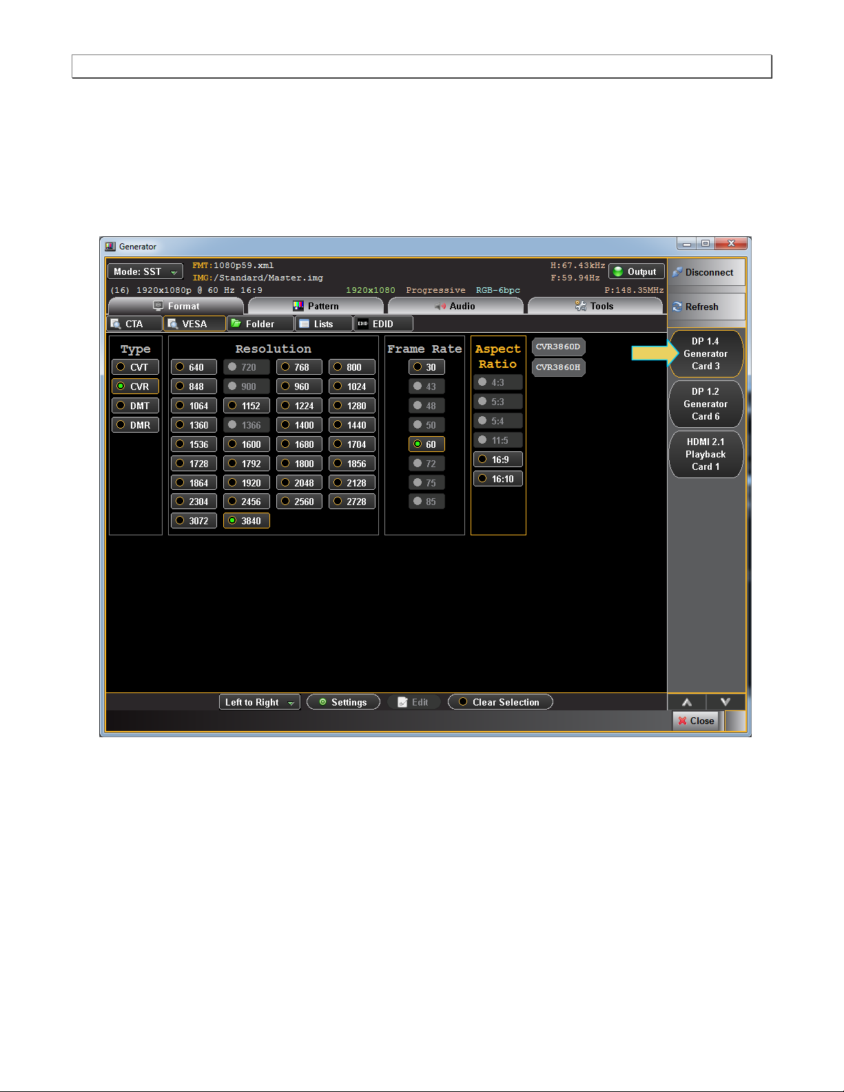
1. From the Main menu of the 980 DP 1.4 Video Generator / Analyzer module, click the DisplayPort Generator
Card button on the right.
Page 26 June 16, 2017
980 DP 1.4 Video Generator / Analyzer - User Guide Rev. A1
When you select the DP module you will get a listing of DP formats in the main window.
Page 27 June 16, 2017
980 DP 1.4 Video Generator / Analyzer - User Guide Rev. A1
3.6 Selecting formats (resolutions)
You can select formats (timings) from the 980 DP 1.4 Video Generator / Analyzer module’s format library or from
the CEA parameter filters. When selecting from the Format Library list, you can select either from the entire list of
formats or you can select from a subset or reduced set of the formats. You can select from a reduced set or subset
of formats in either of two ways:
Select from a custom list you have created using the Format List Editor.
Select from a list of formats configured from the EDID of the connected display.
Use the following procedures to select a video resolution (format).
3.6.1 Selecting formats using the Library list
Use the following procedures to select a video resolution (format) using the Library List method. The procedure
assumes that you have already selected the DP interface.
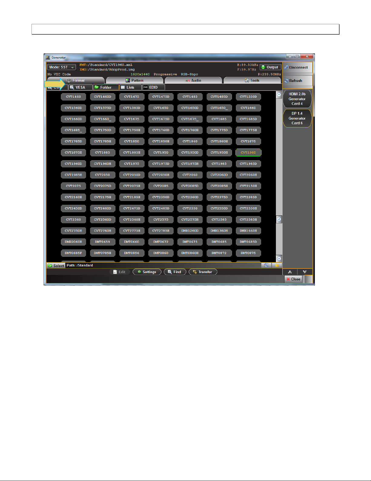
To select a format from the library list:
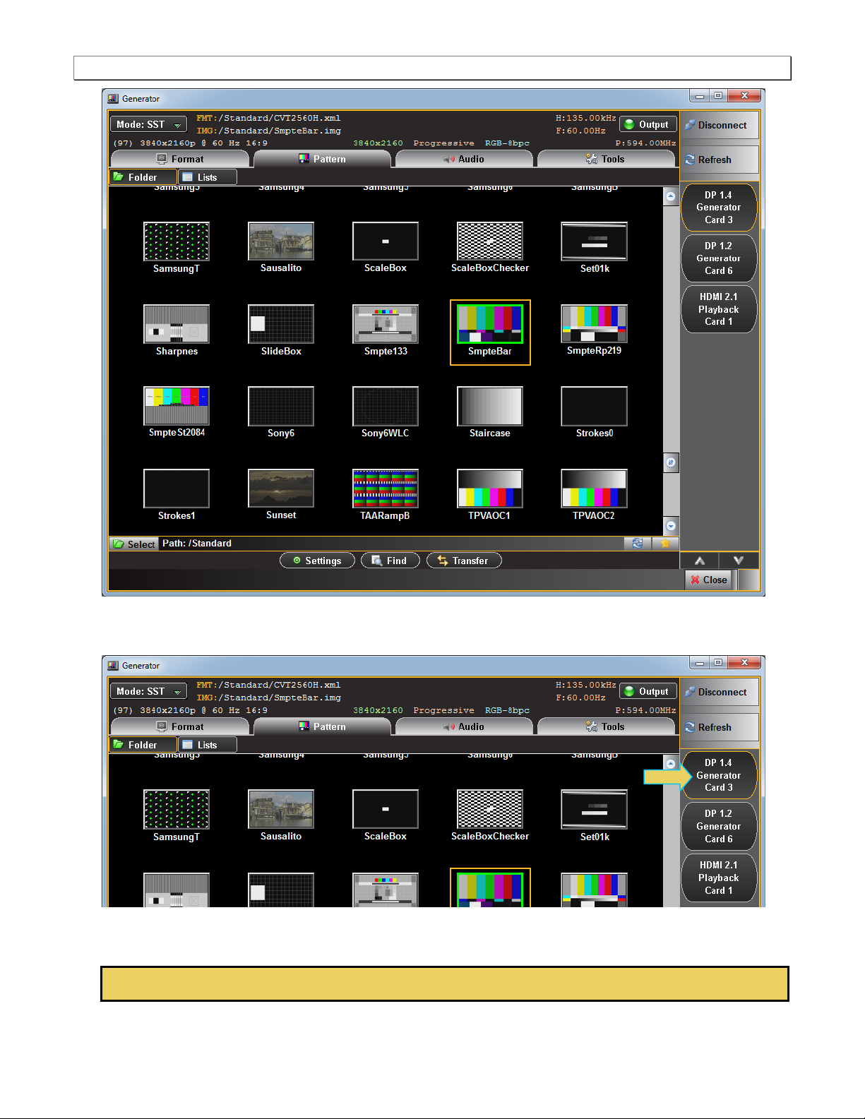
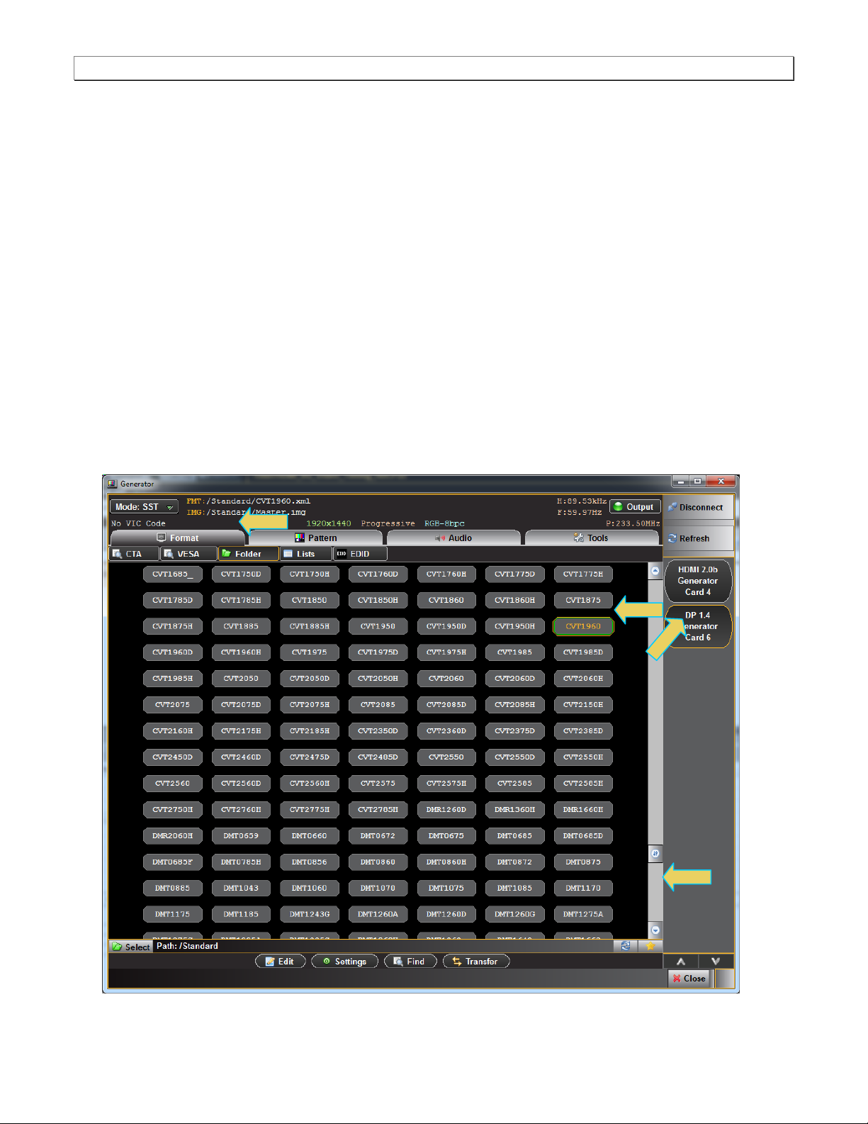
1. From the main window of the 980 DP 1.4 Video Generator / Analyzer module, click the Format tab.
A list of DP, HDMI or DVI formats will appear as shown in the example below.
Page 28 June 16, 2017
980 DP 1.4 Video Generator / Analyzer - User Guide Rev. A1
The highlighted format is the format that is active. You can also determine this from the status information at
the top of the panel. Alternatively you can click on the Star button to show the selected format. When
you click on the Star button the list of formats will be repositioned such that the selected format is shown on the
top line.
2. Note that you can browse for a format using the scroll bar. You can also search for a format using a test strings
on the Find Format dialog box.
3. Select a format from the list by clicking on it.
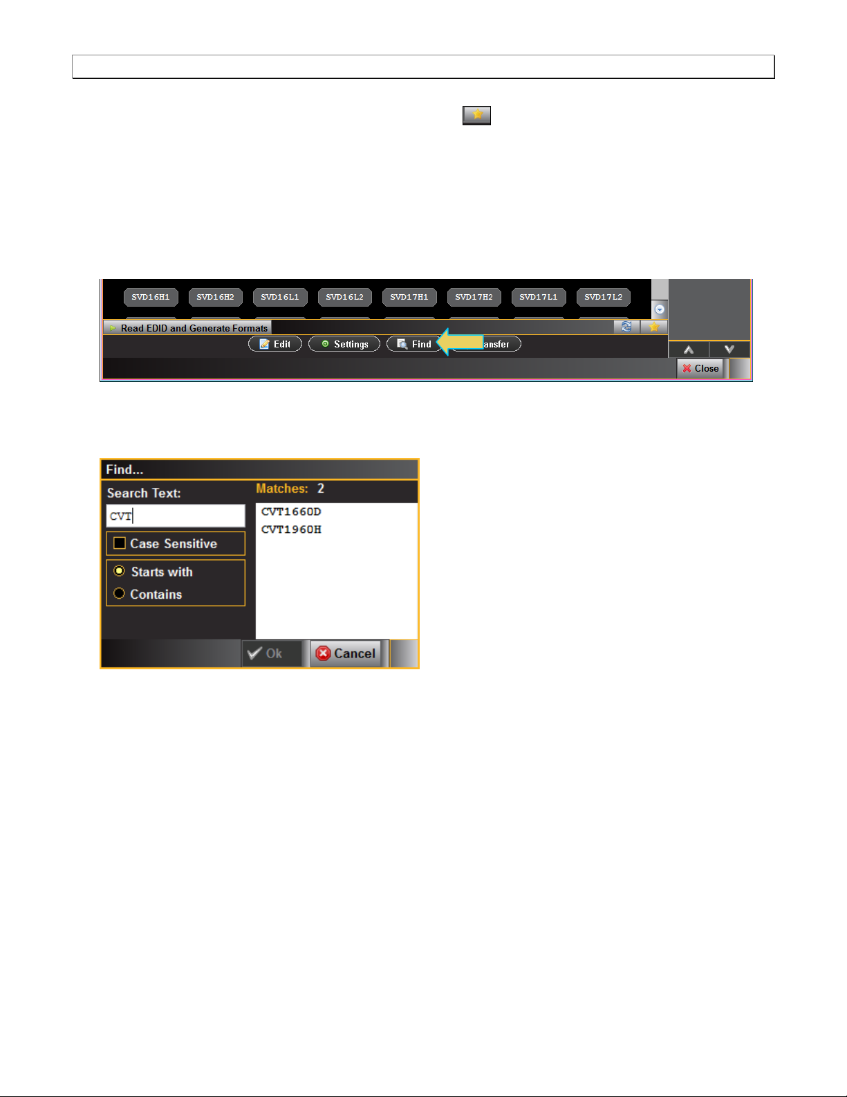
4. Click on the Find activation button on the lower portion of the Format panel.
The Find Format dialog box appears as shown below. Enter a string in the Search Text field to find a format.
You can specify either Starts with or Contains using the radio buttons and you select the Case Sensitive check
box to indicate case sensitivity in your text. Click on the OK button when you have located the format.
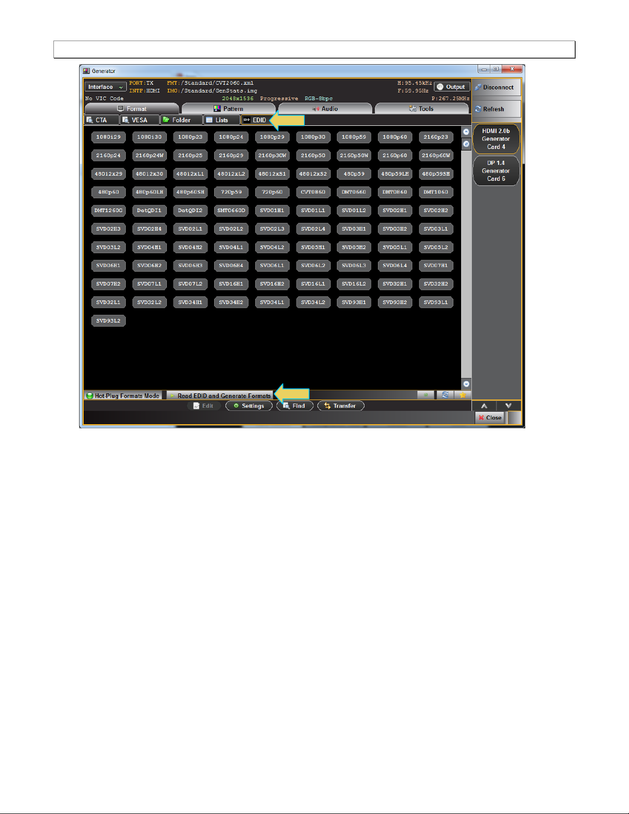
5. Click on the EDID smart activation button on the top left to configure the list of formats in accordance with the
EDID for the connected display.
Page 29 June 16, 2017
980 DP 1.4 Video Generator / Analyzer - User Guide Rev. A1
Page 30 June 16, 2017
 Loading...