

Page 1
Flue Gas Analysis System
Model 9700Model 9700
Model 9700
Model 9700Model 9700
Flue Gas AnalysisFlue Gas Analysis
Flue Gas Analysis
Flue Gas AnalysisFlue Gas Analysis
SystemSystem
System
SystemSystem
InstrInstr
Instr
InstrInstr
uction Manualuction Manual
uction Manual
uction Manualuction Manual
TELEDYNE BROWN ENGINEERING
Analytical Instruments
P/N M48985
10/27/94
i
Page 2

Model 9700
Copyright © 1994 Teledyne Brown Engineering
Analytical Instruments
All Rights Reserved. No part of this manual may be reproduced, transmitted,
transcribed, stored in a retrieval system, or translated into any other language or computer language in whole or in part, in any form or by any means, whether it be
electronic, mechanical, magnetic, optical, manual, or otherwise, without the prior
written consent of Teledyne Analytical Instruments, 16830 Chestnut Street, City of
Industry, CA 917491580.
Warranty
This equipment is sold subject to the mutual agreement that it is warranted by
us free from defects of material and of construction, and that our liability shall be
limited to replacing or repairing at our factory (without charge, except for
transportation), or at customer plant at our option, any material or construction in which
defects become apparent within one year from the date of sale, except in cases where
quotations or acknowledgements provide for a shorter period. Components manufactured
by others bear the warranty of their manufacturer. This warranty does not cover defects
caused by wear, accident, misuse, or neglect. We assume no liability for direct or
indirect damages of any kind and the purchaser by the acceptance of the equipment will
assume all liability for any damage which may result from its use or misuse.
We reserve the right to employ any suitable material in the manufacture of our
apparatus, and to make any alterations in the dimensions, shape or weight of any parts,
in so far as such alterations do not adversely affect our warranty.
Important Notice
This instrument is intended to be used as a tool to gather valuable data. The
information provided by the instrument may assist the user in eliminating potential
hazards caused by the process that the instrument is intended to monitor; however, it is
essential that all personnel involved in the use of the instrument or its interface with
the process being measured be properly trained in the process itself, as well as all
instrumentation related to it.
The safety of personnel is ultimately the responsibility of those who control
process conditions. While this instrument may be able to provide early warning of
imminent danger, it has no control over process conditions, and can be misused. In
particular, any alarm or control system installed must be tested and understood, both as
to how they operate and as to how they can be defeated. Any safeguards required such as
locks, labels, or redundancy must be provided by the user or specifically requested of
Teledyne when the order is placed.
The purchaser must be aware of the hazardous conditions inherent in the
process(es) he uses. He is responsible for training his personnel, for providing hazard
warning methods and instrumentation per the appropriate standards, and for ensuring
that hazard warning devices and instrumentation are maintained and operated properly.
TBE/AI, the manufacturer of this instrument, cannot accept responsibility for
conditions beyond its knowledge and control. No statement expressed or implied by
this document or any information disseminated by the manufacturer or his agents is
to be construed as a warranty of adequate safety control under the user’s process
conditions.
ii
TELEDYNE BROWN ENGINEERING
Analytical Instruments
Page 3

Flue Gas Analysis System
Table of Contents
1 Introduction
1.1 General..............................................................................1
1.2 Sample Conditioning..........................................................2
1.3 Oxygen Analyzer Section..................................................4
1.3.1 Standard Features .............................................. 1-4
1.3.2 Optional Features ...................................................7
1.4 Combustible Gas Analyzer Section....................................9
1.4.1 Operating Controls and Indicators ........................12
1.4.2 Recessed Secondary Controls..............................13
1.4.3 Meter Trim.............................................................13
1.4.4 Analog Output .......................................................13
2 Theory of Operation
2.1 Oxygen Analyzer................................................................1
2.2 Combustible Analyzer .......................................................3
2.3 Detector ............................................................................4
3 Installation
3.1 Electrical Connections .......................................................1
3.1.1 Power......................................................................1
3.1.2 Output Signal Voltage .............................................1
3.1.3 Alarm and/or Control Circuitry.................................3
3.1.4 Output Signal Current .............................................3
4 Operation
4.1 Startup of Oxygen Analyzer ...............................................1
4.1.1 Preliminary ..............................................................1
4.1.2 Meter Zeroing ..........................................................1
4.1.4 Initial Calibration and Equilibration..........................2
4.1.5 Operational Calibration ...........................................4
4.1.6 Routine Operational Calibration..............................5
4.2 Startup of Combustibles Analyzer......................................5
4.2.1 Procedure ...............................................................5
4.2.2 Span Gas ................................................................7
TELEDYNE BROWN ENGINEERING
Analytical Instruments
iii
Page 4

Model 9700
4. 3 System Startup ..................................................................7
4.3.1 Analyzer Startup .....................................................7
4.3.2 Sample System Startup ..........................................7
5 Maintenance & Troubleshooting
5.1 Maintenance ......................................................................1
5.1.1 Routine Maintenance ..............................................1
5.1.2 Oxygen Cell Replacement ......................................1
5.1.3 Cell Warranty ..........................................................2
5.1.4 Spray Nozzle...........................................................3
5.1.5 Water Strainer .........................................................3
5.1.6 Filter Condensate Trap ...........................................3
5.1.7 Combustible Sensor................................................3
5.1.8 Pump.......................................................................4
5.2 Troubleshooting .................................................................4
5.2.1 General ...................................................................4
5.2.2 Oxygen Analyzer Section.....................................5
5.2.2.1 Inability to Calibrate ...................................5
5.2.3 Combustible Analyzer Section ................................6
5.2.3.1 Inability to Calibrate ...................................6
5.2.3.2 No Alarm With High Gas Level ..................7
5.2.3.3 Lamp Failure ..............................................8
iv
Appendix
Specifications.............................................................................1
Recommended Spare Parts List................................................3
Reference Drawings ..................................................................4
Response of Combustible Sensor to Various Gases .................5
Supporting Equipment for Flue Gas Analysis Systems..............7
General Maintenance for CC-2B Series Pumps ........................9
Maintenance ......................................................................9
Repair ................................................................................9
Supplementary Instructions for Servicing the CC-60B Flex-I-
Liner Pump ..............................................................................13
Replacing the Liner in the Flex-I-Liner Pump ..................14
TELEDYNE BROWN ENGINEERING
Analytical Instruments
Page 5

Flue Gas Analysis System General Information
Introduction
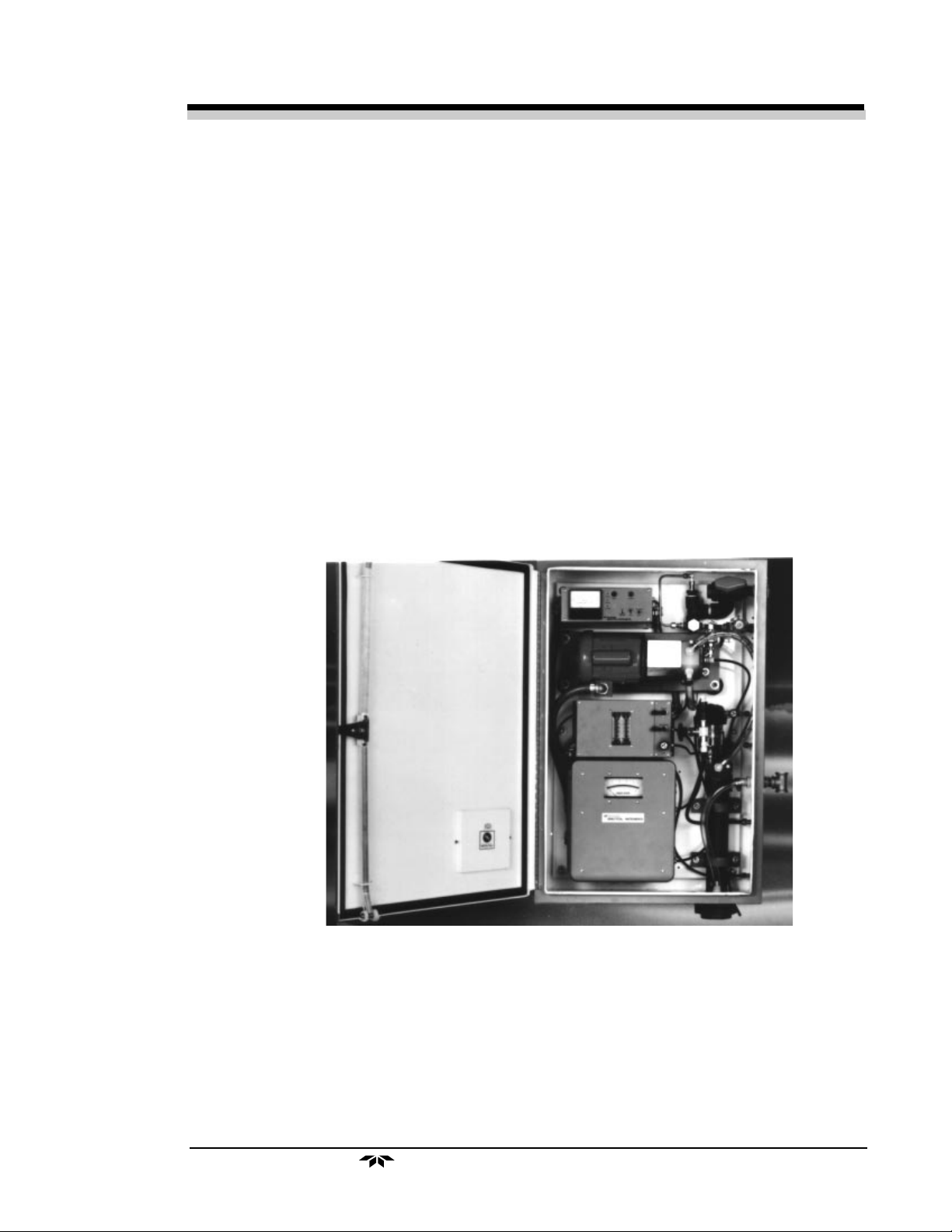
1 Overview
The Model 9700 analyzer system (see Figure 1) is an integrally
housed combination of analyzers designed to continuously monitor the two
primary components of flue gas which are the best indicators of combustion efficiency and safe operation. Through use of volumetric percentage
measurements of oxygen and combustibles, it is possible to optimize the
air-fuel ratio and approach the idealized condition of stoichiometric combustion. Additionally, monitoring of combustibles will assure a safe margin
to prevent combustible mixtures from approaching LEL levels as a result
of a malfunction, before boiler startup, etc. When necessary, appropriate
regulation of the combustion process can be made to reduce nitrogen oxide
(NOx) emissions and resultant air pollution.
The system is composed of the necessary components to educt a flue
gas sample, condition it for analysis, and monitor on a continuous basis the
percentage content of oxygen and combustible gases (see Figure 2).
When required, multipoint configurations, which automatically
monitor from two to twelve points on a time shared basis, are available.
Multipoint sequencing utilizes a stepping switch/timer which operates in
conjunction with a solenoid valve on each sample input to control the time
duration of the inflow. Indicating lights plus a recorder output show which
sample points are being monitored at any given time. Override switches
can be operated to omit any number of sample points from the monitoring
program. If necessary, time delays can prevent the inadvertent tripping of
alarms during the sample sequencing.
TELEDYNE BROWN ENGINEERING
Analytical Instruments
1
Page 6

General Information Model 9700
2 Sample Conditioning
When the flue gas is drawn into the analyzer system, it enters at a
relatively high temperature and carries a significant content of moisture,
dirt and corrosives. The sample stream is preconditioned to cool the gases
and remove contaminants. This processing of the sample assures clean and
continuous operation of the instrument.
A sample stream of flue gas, drawn into the sampling system by
negative pressure, flows through a two-way sample-calibration selector
valve installed at the sample inlet. The valve is used to introduce sample
gas into the system However, when the valve is rotated so that the handle
index faces the inside of the case (open port), atmospheric air is drawn into
a T-joint where a spray nozzle introduces a fine water mist. This mist cools
and wets the sample. A strainer is built into the system to prevent the
nozzle from being clogged by particulates in the cooling water.
Figure 1: Model 9700 Analyzer System
2
TELEDYNE BROWN ENGINEERING
Analytical Instruments
Page 7

Flue Gas Analysis System General Information
Next, the gas and water mixture enter the pump. The pump contains
no valves or packing and will handle the dirtiest of samples without any
detrimental effect
Exiting the pump under positive pressure, the sample mixture is
forced through a mixer which contains a series of baffles which function to
thoroughly scrub the sample gas.
At the next stage of conditioning, the sample solution enters a separator where water is gravitated to drainage. The scrubbed flue gas sample
then exits the separator through a sample outlet and enters a filter-condensate trap for final removal of particulates and water before undergoing
analysis.
The sample gas stream, having passed the final filtration trap, flows
into a tee. Here, the stream is divided with most of the sample gas being
vented to atmosphere, while the balance is routed to the oxygen analyzer
section. Total flow rate is approximately 20 to 30 SCFH. A back pressure
control valve is adjusted to permit proper flow past the oxygen analyzer
sensor where the percentage of oxygen concentration in the flue gas sample
is determined and displayed on the oxygen analyzer meter.
Following oxygen analysis, the sample passes to the combustible
analysis section.
Figure 2: Sample Conditioning
TELEDYNE BROWN ENGINEERING
Analytical Instruments
3
Page 8

General Information Model 9700
3 Oxygen Analyzer Section
The analysis system (see Figure 3) employs a Model 326B Analyzer
which features a TBE/AI unique, patented Micro-Fuel Cell oxygen sensor.
This electrochemical transducer provides an electrical signal that is directly
proportional (and specific) to the oxygen concentration in the gas phase
immediately adjacent to its sensing surface.
The analyzer is capable of oxygen measurements as small as 0.05%
and is unaffected by flow rate changes. Since the sensor is incapable of
producing a significant electrical signal without the presence of oxygen,
any measurable signal produced is “specific” to oxygen.
The Micro-Fuel Cell is completely enclosed, maintenance-free, and
has a predictable life span that is covered by warranty. When the cell is
expended, it is discarded in the same fashion as a worn-out flashlight
battery. TBE/AI’s extensive line of Micro-Fuel Cell equipped oxygenmeasuring instruments are all designed so that the sensor cell can be
replaced in a matter of moments by nontechnical personnel without the use
of tools.
3 .1Standard Features
The oxygen analyzer is housed in a fiberglass equipment case designed to resist the invasion of moisture and dust. The following features
are standard in the Model 326B analyzer:
• Three Ranges of Analysis
Three ranges of analysis are offered 0–5% (Lo), 0–10%
(MED), and 0–25% (HI). Range control is achieved through the
positioning of a panel-mounted RANGE selector switch; the
switch also controls the power on/off to the analyzer. Since one
of the three available ranges of analysis is always 0–25% O2.
ambient atmospheric air (20.9% O2) can always be used to
calibrate the analyzer. A CAL mark on the oxygen meter scale
facilitates calibration. (Although the ranges selected best cover
the oxygen content of flue gas, any three ranges of analysis,
from 0–1% to 0–100%, can be provided. )
4
TELEDYNE BROWN ENGINEERING
Analytical Instruments
Page 9

Flue Gas Analysis System General Information
Figure 3: Oxygen Analyzer Section
• Integral Meter Readout
The analyzer is equipped with a 5" panel meter for direct
readout of the analysis. A linear scale (mirror equipped to
eliminate parallax) promotes reliable, accurate readout of the
analysis at any point on the scale. Resolution and accuracy of
the meter eliminates the necessity of an accessory readout
device, unless permanent recording or remote indication is
required.
• Output Signal
A linear output signal of from 0–1mV dc to 0–1 V dc is
available for those applications requiring a remote indication
and/or recording of the sample oxygen. Unless otherwise
specified, the output signal will be 0–1 V dc.
• Temperature Control and Compensation
To eliminate the inaccuracies caused by varying temperature
conditions that are inherent in most methods of analysis employing transducers, a system composed of a combination of
temperature compensation and control is used in the analyzer.
TELEDYNE BROWN ENGINEERING
Analytical Instruments
5
Page 10

General Information Model 9700
To protect the Micro-Fuel Cell against damage from low
ambient temperatures and reduce the range required of the
compensation circuit, the analyzer is equipped with a
thermostatically controlled heating system that will not permit
the interior of the instrument to drop below 85 deg F.
To eliminate inaccuracies accompanying the positive
temperature coefficient of the Micro-Fuel Cell, a specially
selected thermistor and network of precision resistors are
utilized to produce a negative coefficient of matching
characteristics .
The variable element (thermistor) in the compensation network
is physically located in the same assembly as the Micro-Fuel
Cell so that both devices are exposed to essentially the same
temperature conditions.
• Integral Sample Pump Control
Because the analyzer was essentially designed to measure the
oxygen content of flue gas, provisions for powering and
controlling an electrically driven accessory sample pump have
been built into the analyzer. Terminal strip connections as well
as protective fusing are provided. Pump power is controlled
through the same RANGE switch that controls analyzer power
(see Dwg. B-l0913).
• Modular Electronics
The analyzer is equipped with integrated circuit (IC)
semiconductor electronics. Components are mounted on a plugin printed circuit board, as are various optional electronic
features, i.e., alarms and converter. Printed circuit assemblies
are preset and adjusted for immediate replacement.
6
TELEDYNE BROWN ENGINEERING
Analytical Instruments
Page 11

Flue Gas Analysis System General Information
3.2 Optional Features
The following optional features are available with the system.
• Integral Alarm Circuitry
One (Model 326B-1) or two (Model 326B-2) adjustable, full-
scale alarm and/or control circuits are available.
Control over an external circuit is achieved by a relay
whose solenoid coil is operated by an electronic
“comparator” circuit. The switch contacts of the relay
(NC/C/NO) are available for interconnection with customer
circuitry at the terminal strip within the analyzer. The
control point at which the analyzer operates is determined
by the setting of a calibrated dial-equipped potentiometer on
the control panel.
The 0–10% range of the standard Model 326B is directly
related to the decade nature of the turns-counting dial; the
0–5% and 0–2% ranges require a simple extrapolation
exercise to determine the proper dial reading for a given
oxygen level within the limits of their range.
The integral control circuitry can be arranged so the relay is
energized above or below the setpoint. Unless otherwise
specified, the control relay in a single setpoint instrument
(Model 326B-1) will be energized downscale from the set
position: relays in a double setpoint instrument (Model
326B-2) will be energized when the oxygen level is reading
in the scale region-ion between setpoint #1 in the lower
region of the scale) and setpoint #2 (in the upper portion of
the scale). These configurations provide power supply as
well as oxygen alarm information. The relays are arranged
to be in an energized condition when the oxygen
concentration of the sample is in the safe region of the scale.
The form “C” SPDT relay contacts are rated at 3 amperes
(non-inductive).
TELEDYNE BROWN ENGINEERING
Analytical Instruments
7
Page 12

General Information Model 9700
• E-to-I Converter
A voltage (E) to current (I) conversion of the output signal
generated by the analyzer is available. This conversion allows I
(current) to P (pneumatic) devices, as well as low-impedance
current-operated indicating and/or recording and controlling
instruments to be directly driven without the need of accessory
equipment.
One of the following three ranges of current output is available:
• 1 to 5 mA dc,
• 4 to 20 mA dc
• 10 to 50 mA dc.
The designation 326B-I signifies an analyzer equipped with an E to
I converter.
• Differential Power Supply
Both integral alarm and E-to-I converter options are plug-in
printed circuit boards for quick replacing. When either or both
of the options are employed in an instrument, a highly regulated
differential power supply (also a plug-in printed circuit board)
is included to supply the positive and negative voltage required
by the semiconductor circuitry.
The basic Model 326B employs a simple unregulated power
supply. The rectifying diodes and filtering capacitors are
located on the same circuit board as the detection and amplifier
circuitry. The alarm comparator and converter circuits,
however, require that the supply voltage remain at a constant
level to all circuitry in the interest of accuracy. When options
are employed, the unregulated power supply components are
deleted from the amplifier board, and the amplifier, as well as
the option circuit, are fed from the regulated differential power
supply.
8
TELEDYNE BROWN ENGINEERING
Analytical Instruments
Page 13

Flue Gas Analysis System General Information
4 Combustible Gas Analyzer Section
The combustibles analyzer (see Figure 4) is a compact detector for
reliably sensing all combustible gases. The analyzer consists of two parts:
(1) The control unit housing the calibration controls, analyzer
circuitry, meter readout, alarm relays and power supply.
2) The sensor unit including the sensor, flowmeters, valves and
heater circuit. (Heater power is controlled through the same
RANGE switch that controls oxygen analyzer power (see Dwg.
B-l0913).
Figure 4: Combustible Gas Analyzer Section
TELEDYNE BROWN ENGINEERING
Analytical Instruments
9
Page 14

General Information Model 9700
The sample is sent through one side (SAMP) of twin indicating
flowmeters. Since it is necessary that there is sufficient oxygen in the
sample being analyzed to insure full combustion of any combustible gases
present, the sample is blended, or diluted, with an equal amount of “clean”
compressed air. The compressed air is introduced through the second
(AIR) of the two flowmeters. Two flowmeters are used so that an equal
volume of both sample and air flow can be visually set.
The flowmeters, valves, sensor and associated plumbing are installed
within a temperature controlled box. Temperature is held at about 130 deg
F to keep all components above the dew point of the sample gas.
The sample stream is routed past the combustible gas sensing element.
This element is a low-temperature, catalytic bead type transducer in a
constant current-excited Wheatstone Bridge circuit. Two legs of the bridge
are exposed to the sample gas. The other two legs are passive elements in
the control unit. Gas diffuses into the sensing element and oxidizes at the
catalytic surface of the active or measuring bead, causing its temperature to
rise. The reference bead is not catalytically coated and, consequently, is not
heated by the combustibles. The difference in resistance of the otherwise
matched pair of catalytic beads creates a signal in the bridge circuit. Use of
the uncoated reference bead compensates for the effects of temperature
variations, humidity changes, ambient pressure changes and variations in
line resistance. The signal from the bridge is amplified and displayed on a
meter with a 0–5% combustible range. A diagrammatic illustration of the
combustible sensor is shown in Figure 5.
The beads are installed in a housing which has a flashback arrestor
screen at the sensing aperture to prevent flame propagation back into the
process.
Response of a catalytic bead sensor to a number of gases is shown in
Table I.
An adjustable alarm can be set at any value within the full range. The
latching or non-latching alarm relay can be wired to auxiliary lights, horns,
fans, or used for equipment shutdown.
At completion of combustibles analysis, the sample stream is vented
from the analysis circuit.
10
TELEDYNE BROWN ENGINEERING
Analytical Instruments
Page 15

Flue Gas Analysis System General Information
H
TABLE 1: Detector Response To GASES
COMPOUND LEL* RESPONSE FACTOR
Methane 5.0 1.00
Hydrogen 4.0 0.86
Carbon Monoxide 12.5 0.32
Ethane 3.0 1.20
Ethylene 2.7 1.26
Acetylene 0.5 1.39
Propane 2.2 1.42
Propylene 2.0 1.33
Butane 1.9 1.54
Hexane 1.1 1.50
Cyclohexane 1.3 1.44
Heptane 1.05 1.59
Benzene 1.3 1.50
Pentane 1.5 1.45
Toluene 1.2 1.48
Ethylene oxide 3.6 0.76
Methyl Ethyl 1.8 0.96
Ketone
Methyl Acrylate 2.8 0.59
* Taken from Fire Hazard Properties of Flammable Liquids,
Gases and Volatile Solids, National Fire Protection Agency.
5HIHUHQFH
%HDG
%ODFN
5HIHUHQFH
:KLWH
Figure 5: Combustible Gas Sensor
TELEDYNE BROWN ENGINEERING
Analytical Instruments
&RPPRQ
5HG
0 HDVXU LQJ
$FWLY
%HDG
11
Page 16

General Information Model 9700
4.1 Operating Controls and Indicators
• The POWER toggle switch is used to turn the combustible gas
analyzer ON and OFF.
• The meter displays the gas concentration at the detection point
as a percentage of the combustible gas and is graduated from
0–5% combustibles.
• The green SAFE light is illuminated during normal operation
and indicates that the combustible gas sensing element is
operating.
• The red ALARM light is illuminated either when the
combustible gas concentration rises above the adjustable
ALARM setpoint, or in the event of a sensing element circuit
malfunction. The two conditions can easily be distinguished by
observing the meter reading. In a gas alarm, the meter pointer
will be upscale above the predetermined level. In a malfunction
type alarm, the meter needle will be pegged downscale below
zero. A malfunction alarm will be caused by low or no sensing
element current.
• (optional) The blue FAILURE light is illuminated in the event
of failure of the detector element. The internal buzzer will also
be activated with this type of failure.
• (optional) The amber CAUTION light is illuminated when the
gas concentration rises above the adjustable CAUTION
setpoint.
• The BUZZER toggle switch enables the internal buzzer to
sound if the unit goes into alarm.
Note: This switch is a three position switch. For units that do not contain
a "CAUTION ALARM" , this switch must be in the "full up" position
to activate the AUDIO-BUZZER ALARM. The center and "full down"
positions are "OFF" conditions.
• The AUTO/MAN toggle switch determines the mode of the
alarm relay. In the AUTO mode, the alarm relay will pull in and
drop out automatically as the gas concentration goes above and
below the setpoint. In the MANual position, the alarm relay will
be in a latching mode such as to pull in if the gas concentration
goes above the setpoint. The alarm system can be reset to
normal by switching back to AUTO.
12
TELEDYNE BROWN ENGINEERING
Analytical Instruments
Page 17

Flue Gas Analysis System General Information
4.2 Recessed Secondary Controls
NOTE: The recessed potentiometric controls are provided for calibration
purposes. They should not be changed once calibration is established.
• The SPAN control adjusts for manufacturing variations in
sensitivity between elements and for various gases.
• The ZERO control adjusts for zero meter reading with zero gas
(air) flowing through the sample cell.
• The ALARM control allows the point at which the unit goes
into alarm to be adjusted anywhere between 0% and 5%
combustibles as shown by the meter reading.
• (Optional) The CAUTION control allows the point at which the
unit goes into alarm to be adjusted anywhere within the range of
the instrument as shown by the meter indication.
4.3 Meter Trim
The small potentiometer (P5) located on the main circuit board below
the meter is used to trim the meter to full scale deflection at the rated
output. The potentiometric control is set at the factory.
4.4 Analog Output
An analog (voltage or current) signal is provided for remote monitoring or recording. The type of signal is a customer option.
• Voltage Output
0–1 Volt full scale or less.
NOTE: The remote meter or recorder should have an input impedance
greater than 1K-Ohm.
• Current Output
One of the following milliampere outputs may be
provided:
TELEDYNE BROWN ENGINEERING
Analytical Instruments
13
Page 18

General Information Model 9700
CURRENT MAX LOAD
OUTPUT IMPEDANCE
(mA) (Ohms)
4–20 1K
NOTE: The remote meter or recorder should have an input impedance less
than the indicated values.
14
TELEDYNE BROWN ENGINEERING
Analytical Instruments
Page 19

Flue Gas Analysis System Theory of Operation 2
Theory of Operation
2.1 Oxygen Analyzer
The cathode of the oxygen cell sensor is connected to electrical
ground, while the anode is connected to input amplifier A1., a current-tovoltage transducer. The output voltage from A1 is equal to the input current multiplied by the resistance of the feedback resistor (R1, R2, or R3).
The feedback resistance can be varied by RANGE switch SW1.
Field effect transistor (FET) Q1, connected across A1—2 and A1—3,
is used to short circuit the oxygen cell when the RANGE switch is turned
to OFF. The FET has the property that when the gate is at the same potential as the source, it is turned ‘’on’’. The ‘’on’’ resistance is about 60
Ohms. When power is turned ‘’on”, the -15 VDC turns off the FET (or
causes FET resistance to become greater than 10 Megohms so that it
appears as an open circuit). Thus, when power is turned “on”, the FET is
energized, opens the circuit, and allows cell current to flow through the
feedback resistor instead of through the FET. The reason for this circuit
arrangement is to insure that the oxygen cell is short circuited when power
is turned ‘’off”. The liquid electrolyte in the cell will be depleted of residual oxygen and, consequently, the cell will be ready to operate and measure low concentrations of oxygen immediately after being placed into
service. If the oxygen cell was not shorted when the analyzer was out of
service, the electrolyte within the cell would become saturated with oxygen and, when the analyzer was placed in service, operational delay would
occur while the cell burned up residual oxygen through the process of
TELEDYNE BROWN ENGINEERING
Analytical Instruments
2-1
Page 20

2 Theory of Operation Model 9700
electrolysis. Only after the oxygen is reduced to a low enough concentration can the cell be used to measure the flue gas sample.
The signal from the first amplification stage is connected to a noninverting second stage (A2) which contains a thermistor in its feedback
loop: the thermistor is mounted adjacent to the oxygen cell and is used to
measure temperature of the cell rises and cell output increases, thermistor
resistance decreases and the gain of amplifier A2 decreases in order to
maintain a constant net output voltage for a given concentration of oxygen.
The signal from the first amplification stage is connected to a noninverting second stage (A2) which contains a thermistor in its feedback
loop: the thermistor is mounted adjacent to the oxygen cell and is used to
measure the temperature of the cell. As temperature rises and cell output
increases, thermistor resistance decreases and the gain of the amplifier A2
decreases in order to maintain a constant net output voltage for a given
concentration of oxygen. Potentiometers R7 and R8 are used to correct for
internal offset errors in operational amplifiers A1 and A2, respectively.
The output of A2—6 is scaled to about 2 Volts, then divided down by
SPAN (calibration) potentiometer P1 to 1 Volt, nominal. Readout of the
percent oxygen concentration is provided by meter M1. Resistor R11 is a
meter trimpot potentiometer.
The analyzer circuitry requires 115 VAC, 50/60 Hz, single phase
power which is connected through RANGE switch SW1 to the fused
primary of transformer T1. Rectification, by diodes D1 through D4 connected across the transformer secondary, provides +/- 15 VDC unregulated
to the operational amplifiers. Capacitors C7 and C8 provide a bypass for
stray electrical noise picked up on the power lines, transients, and RF.
AC input power is also connected to a Triac controlled heater circuit.
When temperature rises above the setpoint of thermal switch SW3, heater
H1 is turned off. When the heater contacts close, the Triac is shut off.
When the temperature falls below the setpoint, the Triac and heater are
turned on. The heater and thermal switch are physically located in the
combustible sensor compartment.
2-2
TELEDYNE BROWN ENGINEERING
Analytical Instruments
Page 21

Flue Gas Analysis System Theory of Operation 2
2.2 Combustible Analyzer
The detector assembly and resistors R7 and R8 form a Wheatstone
Bridge. The signal for the bridge is taken from the junction of R7 and R8
for the reference signal which is applied to A1—A3, and from the junction
of the measuring (or active) and reference beads of the detector for the
measuring signal which is applied to A1—2 (See drawing C-11751. Integrated circuit A1 is a differential amplifier whose output (at pin 1) is
proportion l to the difference between the two input signals. Diodes D7
and D8 provide protection to amplifier A1 from high voltage spikes,
transients that might be caused from the long lines connected to the detector, etc.
The ZERO adjustment is made at the potentiometer P1. The adjustment is made by unbalancing the bridge. Potentiometer P1 is connected to
the same supply voltage as the bridge with resistor R9 connected to the
center of the reference side of the bridge. This arrangement provides
sufficient unbalance voltage to compensate for the unbalance of the
sensor.
Amplifier A1 is set up with a gain of about 20, nominally for 5%
methane. The output at A1-1 is about 2 volts nominal full scale. One volt is
picked off at the center of the SPAN potentiometer P2 in order to drive the
voltage follower (the other half of A1) which provides isolation of the
first-stage amplifier from the remainder of the circuitry. Resistor R32 and
Capacitor C18 filter out any noise that might have come in on the detector
lines, electrical transients, etc.. The output from A1—7 also provides an
analog signal output that is selectable by varying the values of R28 and
R29.
ALARM potentiometer P3 is the setpoint adjustment for the alarm.
When the output from the gas amplifier goes higher than the setting of P3,
transistor Q1 is turned on and relay K2 is energized, resulting in an alarm.
A BUZZER toggle switch, when placed in the ALARM setting, allows an
internal buzzer to sound, indicating that the unit has gone into alarm.
Additionally, illumination of a red ALARM light indicates an alarm (while
illumination of the green SAFE light indicates normal operation). If the
AUTO/MAN toggle switch is set to MAN, the alarm latches and it is
necessary to switch to Al, to AUTO to unlatch the alarm.
As noted previously, relay K2 is energized when an alarm occurs.
With no alarm, the normally closed contact is closed and the normally
open contact is open. When an alarm condition occurs, the contacts transfer
and reverse their normal state.
TELEDYNE BROWN ENGINEERING
Analytical Instruments
2-3
Page 22

2 Theory of Operation Model 9700
An optional CAUTION alarm circuit utilizes potentiometer P4 to
establish the setpoint. When the setting of P4 is exceeded. transistor Q2 is
turned on and relay K1 is energized, resulting in an alarm.
The optional FAILURE alarm circuit is set up so that if the detector
opens up, an alarm comparator will trip and turn off a relay, which is
normally energized, i.e., during the non-alarm condition, the normally
open contact will be closed and the normally closed contact will be open.
The power supply circuitry includes transformer T1 which is a 40-volt
center-tapped unit. Two sets of rectifiers are used to supply two regulated
power circuits and +/-24 VDC unregulated. The circuit that includes Zener
diodes ZD2 and ZD3 supplies +/-15 VDC regulated. Regulator VR2 is the
current regulator for the detector. This regulator is set up so that current
through the detector is determined by resistors R4 and R5. Current output
of 0.3A can be measured at a pair of test points. Capacitor C9, connected
across the input, gives protection from line transients, high voltage spikes,
etc.
2. 3 Detector
The basic elements of the combustible gas detector are shown in
Figure 5. The two beads each consist of a very small coil of wire coated
with an appropriate material. The active (or measuring) bead coating is a
mixture of a catalytic material with an inert binder. This catalytic material
is selected to enhance the oxidation of combustible gases. The reference
bead coating is an inert material having similar thermal properties to the
other bead.
Upon exposure of the detector to an atmosphere containing combustible gases and oxygen, these will combine at the surface of the measuring bead. Energy produced by this reaction will heat the active bead and
cause the electrical resistance of its wire coil to change. The change in
resistance of this coil is, then, for a particular gas, a measure of the reaction
rate at the bead surface. The reaction rate and energy production depend
strongly on the nature of the gas. By raising the temperature of the bead,
the reaction rate can be increased, making the effects of different gases
more nearly equal. Thus, the sensitivity of the detector is made greater and
more nearly equal for different gases. This heating is accomplished by
passing a constant electrical current through the wire coil supporting the
bead.
2-4
TELEDYNE BROWN ENGINEERING
Analytical Instruments
Page 23

Flue Gas Analysis System Theory of Operation 2
The temperature of the active bead will be influenced by other factors
such as initial gas temperature, gas thermal conductivity, flow rates and the
temperature of its housing. The reference bead, having similar electrical
and thermal properties and being heated by the same current, but lacking
the catalytic material will be similarly affected by these extraneous factors
but not significantly affected by oxidation of the combustible gas.
These two beads are placed in close proximity. to one another so that
they are affected by the same environmental factors. Thus, the differences
between the changes in resistance of the two coils is directly related to the
concentration of combustible gases.
TELEDYNE BROWN ENGINEERING
Analytical Instruments
2-5
Page 24

2 Theory of Operation Model 9700
2-6
TELEDYNE BROWN ENGINEERING
Analytical Instruments
Page 25

Flue Gas Analysis System Installation 3
Installation
3.1 Electrical Connections
All wiring is to be connected to the barrier type terminal strips on the
back plate assembly within the analyzer. Refer to Figure 6, Interconnection
Diagram, and be certain that the wiring installation complies with the
directions contained in the illustration and in the following discussion.
3.1.1 Power
Refer to the drawings in the supplement at the back of this manual.
All power inputs are fused in order to protect the pump in addition to the
analyzer electronics.
3.1.2 Output Signal Voltage
All models of the analyzer are equipped to provide an output signal
voltage. The magnitude of the signal, which is determined at the time of
purchase, can be preset at the factory to any value between 1 mV and 1 V.
Unless otherwise specified, the outpur will be set to 0–1 VDC.
The output signal, regardless of magnitude, is suitable for highimpedance devices only (10K Ohms min.).
For interconnection purposes, 22 guage AWG shielded cable conductor is recommended. Polarize the signal connections as shown in Figure 6
and connect the shield to the analyzer only.
TELEDYNE BROWN ENGINEERING
Analytical Instruments
3-1
Page 26

3 Installation Model 9700
1&
6( 737
&
`
12
1&
6( 737
&
`
12
0$6,* 1 $/ 287
`
2; <* (1
$1$/ <=( 5
`
(0)6,* 1$/ 287
*1'
1( 87
/,1(
+]
6<67( 0
`
32 : ( 5 ,1
$/ $5 0 &,5&8,7
2; <* (1$1$/ <=( 5
`
6,* 1 $/ 287
&20 %867,%/ (
`
$1$/ <=( 5
$/ $5 0
1&
&,5&8,7
&
&20 %867,%/ (
`
$1$/ <=( 5
12
76
Figure 6: Interconnection Diagram
Note: Ground the shield of the signal cable at the analyzer only as shown
in the diagram. Do not ground either output signal lead. Power and
signal leads should be placed in separate conduits.
76
Wire recommendations:
Signal:22 Ga. shielded cable (no shield required for mA signal).
Power and Ground: 16 Ga
Alarm Circuit Wiring: 16 Ga.
3-2
TELEDYNE BROWN ENGINEERING
Analytical Instruments
Page 27

Flue Gas Analysis System Installation 3
3.1.3 Alarm and/or Control Circuitry
Models having a -1 or -2 as part of their model number are equipped
with single (-1) or double (-2) alarm and/or control circuits.
The SPDT form "C" (NC/C/NO) contacts of the relay (or relays) are
available on the terminal strip within the oxygen analyzer. To properly use
the switch that the relay contacts represent, the customer must determine
when the relay (or relays) is energized (above or below the setpoint). The
appropriate terminal strip connections are identified on the interconnection
diagram (see Figure 6).
For those not familiar with relay terminology, the terms normally
open (NO) and normally closed (NC) refer to the relay contact configuration when the relay is in a de-energized condition.
The load current per relay must be limited to 3 Amperes non-inductive.
3.1.4 Output Signal Current
Instruments which include the designation "I" as part of their model
number are equipped with an E-to-I converter to provide a DC milliampere
(mA) output signal as well as a DC voltage signal.
A separate 1/4 ampere slow-blow fuse, located on the analyzer control
panel, protects this circuitry.
The range for current output is:
• 4–20 mA dc
Suitable for devices with 0–1500 Ohms impedance
(resistive).
The appropriate terminal strip connections are identified on the
interconnection diagram (see Figure 6).
TELEDYNE BROWN ENGINEERING
Analytical Instruments
3-3
Page 28

3 Installation Model 9700
3-4
TELEDYNE BROWN ENGINEERING
Analytical Instruments
Page 29

Flue Gas Analysis System Operation 4
Operation
4.1 Startup of Oxygen Analyzer
4.1.1 Preliminary
Before applying power to the instrument, TBE/AI suggests that the
electrical wiring installation be checked against the interconnection diagram (see Figure 6), especially if the installation has been made by personnel other than those responsible for startup and operation. In many instances, proper attention to this preliminary check will prevent severe
damage due to accidental wiring transpositions.
4.1.2 Meter Zeroing
Before turning power to the analyzer on, (RANGE switch in any
position but OFF), the mechanical zero of the meter should be checked and
adjusted, if necessary. The meter indicating pointer should be in precise
coincidence with the scale zero mark. Use the mirror to eliminate parallax;
adjust the screw on the face of the meter to zero the pointer. Zeroing of the
meter is important to achieve maximum accuracy of the meter, and even
more important if remote indicating and/or recording equipment are involved in the system. An offset zero on the meter will result in a tracking
error between the two devices which would be significant if the meter is
used to calibrate the analyzer (normal procedure).
CAUTION: Never attempt to make this adjustment with the power on.
TELEDYNE BROWN ENGINEERING
Analytical Instruments
4-1
Page 30

4 Operation Model 9700
The Micro-Fuel Cell is supplied separately in a controlled atmosphere
package and must be installed prior to startup. To install the cell, use the
following procedure:
Note: Do not open the sealed package until the system is to be started
and a flue gas sample is available .
(1) Make sure that the RANGE switch is in the OFF position
(power “off”).
(2) Locate the cell holder assembly (white unit on the back plate
assembly) and withdraw the cell probe from its holder, using a
twisting motion. Remove the cap by unscrewing counterclockwise (CCW).
(3) Open the cell package and remove the shorting clip .
(4) Place the Micro-Fuel Cell in the probe with the gold colored
sensing surface facing toward the outside, and the printed
circuit contact end facing the contacts inside the probe body.
Replace cap previously removed (refer to instructions in the cell
box).
(5) Insert the cell probe back into the probe holder bv pushing it in
with a slight twist until the the probe strikes bottom.
4.1.4 Initial Calibration and Equilibration
Before stable, reliable operation can be achieved, the Micro-Fuel Cell
requires a period of time to adjust to its new environment. When observing
the integral meter, this period of time will appear to be about 15 minutes.
In actuality, however, true stability is not achieved for many hours, which
can be demonstrated by recording the output on a circular chart recorder,
then analyzing the results of the first 24 hours of operation. The user will
note a few percentage points of drift covering a period of hours after the
initial first 15 minutes of equilibration.
If speed is of the essence, TBE/AI suggests that the instrument be
placed in service atter it appears to have stabilized (usually about 15
minutes), and the slight instability of the ensuing hours tolerated. Any error
incurred during this period will be eliminated during the first operational
calibration.
4-2
TELEDYNE BROWN ENGINEERING
Analytical Instruments
Page 31

Flue Gas Analysis System Operation 4
If, on the other hand, reliable analysis, free of instrument distortion, is
required from the very onset of operation, TBE/AI recommends a 24 hour
run-in period before operational calibration and service .
In either case, emlploy the following procedure:
(1) Set the analyzer RANGE switch to the 0–25% position. Power
has now been applied to the instrument circuitry and to the
sample pump.
(2) Rotate the sample-caibration selector valve so that calibration or
span gas is being delivered to the analyzer.
Note: When the valve is rotated so that the handle index faces the inside
of the case (open port), atmosplleric air is drawn in by the pump
and flows through the oxygen analyzer. Be sure that the valve is
returned to the sample inlet position after calibration is completed.
Never leave the valve in the half-way (closed) position with the
pump running.
(3) Allow air to flow through the unit for 3 to 5 minutes.
(4) Unlock and adjust the SPAN control until the meter pointer is
in coincidence with the CAL mark (20.9% O2) on the meter
scale. Relock the SPAN control.
(5) Rotate the selector valve so that sample gas is flowing through
the analyzer.
(6) Select the range of analysis that will provide the best possible
resolution of the oxygen content of the sample gas.
(7) Allow sample gas, not calibration air, to flow through the
analyzer for the duration of the equilibration period.
Note: It is particularly vital to the condition of the A-3 cell employed in
flue gas (or high CO2 content applications) that the cell not be
exposed to a CO2 free environment for a prolonged period of time.
TELEDYNE BROWN ENGINEERING
Analytical Instruments
4-3
Page 32

4 Operation Model 9700
4.1.5 Operational Calibration
After the equilibration period following the installation of any new
cell, or whenever it is desirable to recheck the calibration of the instrument, use the following calibration procedure:
(1) Place the RANGE selector switch on the 0+25% Position.
(2) Rotate the selector valve so that calibration (or span) air is
flowing.Allow air to flow for 3 to 5 minutes.
(3) Unlock and adjust the SPAN control until the meter pointer is
in precise coincidence with the scale CAL mark (use the mirror
to eliminate parallax) and relock the SPAN control.
(4) Return the instrument to service by restoring sample flow and
selecting the range that provides the best possible resolution of
the sample oxygen .
(5) To prevent generating ambiguous alarms during calibration of
alarm equipped instruments, simply unlock and rotate the
setpoint dial (or dials) until the limits of travel in the NORMAL
(rather than ALARM) direction have been attained. After
sample flow has been reestablished and the proper scale of
analysis selected, the alarm point can be precisely reset by
simplre-dialing the setpoint.
(6) For converter-equipped instruments, the current output of the
converter always tracks the output of the measuring circuit
amplifier. No provision for interlocking the converter to a
particular range of analysis has been provided. If the current
output is being used to operate a pneumatic control device, the
customer will be required to provide whatever necessary
electrical or mechanical interlocks necessary to safeguard his
system against the signal changes that will occur during
calibration.
4-4
TELEDYNE BROWN ENGINEERING
Analytical Instruments
Page 33

Flue Gas Analysis System Operation 4
4.1.6 Routine Operational Calibration
Span calibration should be checked every two to four weeks on a
routine basis. Whenever there is the slightest suspicion of abnormal performance, an inspection of the possible trouble should be made, followed by
span calibration. Use trouble shooting procedures as required.
4.2 Startup of Combustibles Analyzer
4.2.1 Procedure
The combustibles monitor comes ready to operate. Power is connected to it through a terminal strip in the oxygen analyzer (see Figure 6).
The combustibles monitor has Its own POWER switch located on the front
panel of the control unit. Alarm relay and analog output terminals are
located in the oxygen analyzer.
When ready to operate, follow the startup procedure in Section 4.3
Startup Procedures, except as follows:
(1) Turn on the air supply and adjust the AIR regulating valve on
the valve panel until I flow rate of 2–3 SCFH is indicated on the
lefthand flowmeter.
(2) Open the SAMPLE toggle valve and open the sample/bypass
control valve fully CCW. The sample/bypass control valve is
the valve on the outlet of the filter.
(3) Start up the svstem pump and with either calibration air or
sample flowing, slowly close the sample/bypass valve until a
flow of 2–3 SCFH (matching air flow) is indicated on the
righthand flowmeter. The flowmeter ball will have some
bounce due to water column fluctuation in the system. Adjust
for an average value.
Note: Do not attempt to run a higher flow rate than 3 SCFH. Higher flow
rates will cause the water trap to break and all flow will be lost
through the drain.
(4) Turn ON the POWER switch of the combustible monitor
control unit. Wait about five minutes for the unit to warm up.
(5) Shut off the SAMPLE toggle valve and let only air flow
through the unit.
TELEDYNE BROWN ENGINEERING
Analytical Instruments
4-5
Page 34

4 Operation Model 9700
(6) After air has been flowing for a couple of minutes, adjust the
ZERO control on the control unit (use the small screwdriver
supplied) until the meter pointer lines up with the zero mark on
the dial (be sure that the mechanical zero of the meter is first
adjusted with the power off.)
(7) Turn on supply of span gas and open the SPAN toggle valve.
Then adjust the SPAN flow control valve until a flow rate of
2–3 SCFH is indicated on the right hand flowmeter.
Note: Flow rate of span gas should be set to match that of the air as
closely as possible. It does not matter what they read as long as
they are both the same.
(8) Adjust the SPAN control with the small screwdriver until the
meter pointer reads the analyzed value ot the span gas.
(9) If only a very small or no adjustment was required, no further
calibration should be needed. If, however, a fairly large
adjustment was made, the ZERO adjustment should be
rechecked and readjusted, as necessary. If ZERO readjustment
was made, check the SPAN adjustment again.
(10) Adjust alarm setpoint to the desired level. The alarm is
adjusted by turning ZERO control until the meter reads the
desired alarm point. The ALARM level control is then adjusted
until the alarm light just comes on. The ZERO control must
then be reset to produce a zero reading.
(11) Once the above adjustment has been made, the unit is ready
for service.
(12)After calibration is completed, re-establish sample flow and be
sure the flow rate is set to match that which was used for span
gas.
4-6
TELEDYNE BROWN ENGINEERING
Analytical Instruments
Page 35

Flue Gas Analysis System Operation 4
4.2.2 Span Gas
It is recommended that the span gas have a concentration of 4.0–4.8%
methane or other desired combustible gas with the balance being nitrogen.
Note: It is important that the dilution air flow is never turned off during
operation or calibration. Combustibles without at least a 2 : 1 ratio
of oxygen should never be allowed to flow past the sensor. If this
occurs, a loss of sensitivity will result and the unit will require
complete recalibration and possible sensor replacement.
Note: The range of the combustible monitor is 0–5% combustibles,
however, it is actually operating, at a sensitivitv of 0–2.5% combustibles (methane equivalvent) due to the 1 : 1 dilution with air.
4. 3 System Startup
4.3.1 Analyzer Startup
Refer to Sections 4.1 and 4.2 for startup procedures for the oxygen
and combustibles analyzers, respectively.
4.3.2 Sample System Startup
Start the pump by turning ON the oxygen analyzer RANGE switch.
Then turn on the water by opening the shutoff valve inside the case. Water
should be observed passing through the transparent plastic hoses. Water
flow rate will be determined by the supply pressure. With 10 psig, flow
rate will be approximately 1/4 gpm maximum pressure should be 100 psig.
This will give a flow rate of about 11/2 gpm. Generally, the dirtier the
sample, the more water required. However, a 1/4 gpm flow rate will normally be adequate, and the pressure should be reduced accordingly.
After analyzer startup and calibration procedures have been accomplished, make certain that the sample-calibration selector valve is in the
proper position to draw in the sample (see the cautionary note in step (2) of
Section 4.1.4, Initial Calibration and Equilibration, and step (5)).
TELEDYNE BROWN ENGINEERING
Analytical Instruments
4-7
Page 36

4 Operation Model 9700
4-8
TELEDYNE BROWN ENGINEERING
Analytical Instruments
Page 37

Flue Gas Analysis System Maintenance & Troubleshooting 5
Maintenance & Troubleshooting
5.1 Maintenance
5.1.1 Routine Maintenance
No moving parts other than the meter movement and the relay contacts are contained in the analyzers. Periodic service, therefore, other than
oxygen cell replacement, is not required. The periodic calibration contained in Sections 4.1 and 4.2 should be adequate to keep the analyzers
functioning. If troubles develop, refer to the trouble shooting procedures
contained in Section 6.
5.1.2 Oxygen Cell Replacement
When the Micro-Fuel Cell nears the end of its useful life, sensitivity
will decline very rapidly. The initial response to this phenomenon will be
recalibration of the analyzer. If many turns of the SPAN control are required to recalibrate the instrument, or more commonly, the control does
not have sufficient range to recalibrate the analyzer, a new Micro-Fuel Cell
will be required.
Wipe off contact pins (P/N A-6544) in the probe assembly with a
clean tissue before installing the new cell. If, after long service, the contact
pins become pitted or worn, they may be replaced by unscrewing the holddown plate.
To offset the possibility of not having a replacement cell available
when it is needed, TBE/AI recommends that a spare cell be ordered shortly
after the instrument is placed in service, and each time the cell is replaced
thereafter.
TELEDYNE BROWN ENGINEERING
Analytical Instruments
5-1
Page 38

5 Maintenance & Troubleshooting Model 9700
Note: Do not over-order or stockpile Micro-Fuel Cells. Only one cell per
instrument should be kept in reserve.
When installing the oxygen cell in the probe housing, make certain
that the shorting clip is re- moved and that the cell membrane is facing up
(or outward). Do not install the oxygen cell upside down.
Caution: When replacing the oxygen cell, use care not to scratch the
membrane covering the gold-plated electrode. If the membrane
is ruptured or damaged in any way, the sensor must be replaced.
The oxygen cell contains a caustic liquid (potassium hydroxide solu-
tion). If the Teflon membrane is ruptured, the liquid in the cell can leak
out. The liquid has a characteristic slippery feel and if contact with the skin
or eyes occurs, wash with copious amounts of water and seek medical
attention, if required.
Note: Do not install an oxygen cell into a system that is in storage or in a
non-operating condition. The oxygen cell will commence the oxidation process and eventually will become useless as a sensor. Also,
when the on-line system is shut down for a short time, every effort
should be made to adjust the controls in the system to prevent air
from coming into contact with the Micro-Fuel Cell.
5.1.3 Cell Warranty
The A-3 Micro-Fuel Cell carries a warranty that covers its normal life
expectancy. Cell warranty is for 6 months of continuous service in normal
flue gas applications.
Customers having warranty claims should return the cell in question
to the factory for evaluation. If it is determined that failure is due to faulty
material or workmanship, the cell will be replaced free of charge.
Note: Evidence of tampering or abuse will render the warranty null and
void. If the cell was working satisfactorily, but fails short of its
warranty period, the customer will receive credit, on a prorated
basis, towards the purchase of a replacement cell.
5-2
TELEDYNE BROWN ENGINEERING
Analytical Instruments
Page 39

Flue Gas Analysis System Maintenance & Troubleshooting 5
5.1.4 Spray Nozzle
It will be necessary to clean the mineral deposits from the spray
nozzle periodically (see Figure 1). If water flow through the system diminishes significantly, it is an indication that the nozzle is plugged. The
nozzle can easily be <cleaned by removing it and soaking it in a 25%
hydrochloric acid solution.
CAUTION: Use extreme care when using hydrochloric acid. Do not allow
any solution to contact the skin or clothing. If acid contacts the
skin, flush the exposed areas continuously for 5 to 10 minutes
or until medical attention can be obtained. Do not breath hydrochloric acid vapors. Use only in an approved vented safety
hood.
5.1.5 Water Strainer
It may be necessary to clean the screen in the strainer periodically (see
Figure 1). This is accomplished by unscrewing the brass hex plug on the
front of the unit and removing the screen.
5.1.6 Filter Condensate Trap
Any accumulated water must be emptied from the condensate trap
before the water level reaches the filter element (see Figure 1). This is
accomplished by simply pressing sideways on the flexible drain spout on
the bottom of the bowl. The filter element should also be cleaned periodically by washing it with kerosene and blowing it dry with compressed air.
The part number of the element is listed in Table 3.
5.1.7 Combustible Sensor
The combustible sensor is installed along with the H-28 heater and
T-199 thermoswitch in the sensor unit enclosure. These components can be
removed for replacement, if required.
TELEDYNE BROWN ENGINEERING
Analytical Instruments
5-3
Page 40

5 Maintenance & Troubleshooting Model 9700
5.1.8 Pump
The pump (shown in Figure 1) uses a flexible Nordel liner which is
actuated by a roller on an eccentric. This liner requires oiling weekly. The
pump is equipped with an oiler which holds a large supply of oil. Use the
following procedure to oil the liner:
• Fill the oiler. (This needs to be done only occasionally.)
• Once the oiler is filled, it is only necessary to open the toggle
valve on the top of the oiler.
• Shut off the pump and let 7 or 8 drops of oil fall in the sight
glass of the oiler.
• After about two minutes, restart the pump.
• Close the toggle valve on the oiler when finished.
If the liner is oiled routinely, it should last about 6 months to a year.
Replacement of the liner will restore any noticeable loss in pumping
efficiency.
Any water coming out of the pump liner vent line (at the bottom of
the separator) is an indication that the liner is worn through and needs to be
replaced. Detailed pump maintenance instructions can be found in the
Appendix of this manual.
Note: Use only Venton Pump oil or pure silicone oil of 2000 centistokes
viscosity. Do not use organic oil.
5.2 Troubleshooting
5.2.1 General
Trouble shooting information contained herein is limited to the electronics of the system. It is felt that malfunctions occurring in the pneumatic
portion of the system can be remedied by personnel familiar with valving,
regulation, and standard mechanical engineering. The electronics portion
of the system, however, includes advanced solid state, integrated circuitry.
Technicians involved with trouble shooting the electronics of the system
should be familiar with common diagnostic equipment and techniques.
5-4
TELEDYNE BROWN ENGINEERING
Analytical Instruments
Page 41

Flue Gas Analysis System Maintenance & Troubleshooting 5
When subjecting the analyzer circuits to checkout, it is appropriate to
first check the power supplies for correct output. If voltages are incorrect,
then take corrective action with power supply components .
5.2.2 Oxygen Analyzer Section
5.2.2.1 Inability to Calibrate
If the oxygen analyzer cell circuit exhibits insufficient amplifier
gain, or if it is impossible to adjust the output signal with the SPAN
potentiometer, the oxygen cell is probably used up. This process will
require some time; it will not happen immediately. Before replacing
the cell, however, check the sample circuit to make sure that the
sample is actually getting to the cell.
If the cell is functional, or there is still no output with
installation of a new cell, then a check of the electronics should he
undertaken.
• First, check the power supply. Make sure that proper
voltages exist at A1-7, (+15 VDC), A1-4 (-15 VDC),
A2-7 (+15 VDC), and A2-4 (-15 VDC).
• If voltages are satisfactory, check output of A1 at pin 6.
(It will be easier to check the output of A1 at the tiepoint
of resistors R1/R2/R3.) Use the tiepoint of C7 and C8 as
the power common. The voltage (output of A1) should
be 0.125 V with a full scale signal. If the oxygen cell is
exposed to 20.9% oxygen, the voltage at A1-6 should be
about 0.1 VDC.
• If the voltage at A1-6 is satisfactory, then check the
output of A2 (at A2-6). (It will be easier to check the
output of A2 at the tiepoint of R9 and C6.) Use the
tiepoint of C7 and C8 as the power common. The
voltage (output of A2) should be 2 V full scale. If the
oxygen cell is exposed to 20.9% oxygen, the voltage at
A2-6 should be 1.5 to 1.75 VDC .
In addition to possible malfunctions occurring in Al and/or
A2, the FET (Q1) could be malfunctioning, i.e., not being turned off.
If Q1 is “on” all the time, the oxygen cell will be shorted and no signal
will be able to get through the feedback resistors for A1.
TELEDYNE BROWN ENGINEERING
Analytical Instruments
5-5
Page 42

5 Maintenance & Troubleshooting Model 9700
The best way to check Q1 is to remove it, then check it, or
substitute a replacement .
The meter drive circuitry, as shown on Dwg. B-l0913, is
straightforward and relatively simple to follow. If any troubles occur
in this circuitry, consult the schematic diagram.
The heater (H1) control is controlled by SW3, R15 and the
Triac (SCR1). During various periods of the heater cycle, both R15
and SW3 are required to carry a heavy load. Consequently, it is
possible for either component to fail.
The Triac can fail as well. If it fails in the “open” condition
there will be no heat from the heater. If it fails in the “closed”
condition, the heater will be on all the time. Heater malfunction will
probably be evident with calibration problems involving the
combustibles sensor, since the heater is installed in a compartment
with this particular sensor.
5.2.3 Combustible Analyzer Section
Refer to drawing C-11751 for the following discussion.
5.2.3.1 Inability to Calibrate
The most common cause of an inability to zero and/or span
the instrument is detector failure. The combustible detector will drift
in both span and zero with time. However, if it fails, it is most likely
to be an abrupt phenomenon, unlike the oxygen cell which “dies”
slowly. Upon failure, the output of the instrument will go up or down
full scale depending upon which bead fails.
The standard combustible analyzer used in the Model 9700
system includes a failure alarm circuit that is described in Section 2.2.
As described, a failure will cause the meter to deflect full scale downward (pegged to the lefthand side of the meter) and the alarm will be
energized. This situation will indicate a sensor failure.
The sensor circuit can be checked either with a new sensor or
a dummy sensor, constructed with two 7.5 Ohm 3 to 5 Watt resistors
installed between pins 14 and 15, and 14 and 13 (see Dwg. C11751).
With the dummy sensor, the zero and span potentiometers will both
function and the and the electronics can be checked. If the span and
zero controls operate satisfactorily with the dummy sensor, then the
5-6
TELEDYNE BROWN ENGINEERING
Analytical Instruments
Page 43

Flue Gas Analysis System Maintenance & Troubleshooting 5
original detector is probably defective and requires replacement. If
problems still occur in the detector circuit, then the dummy sensor
will give a signal that can be tracked through the system.
• Measure the voltage at the tiepoint of R7, R8 and R10 with
respect to terminal 14 which is the center of the sensor bridge.
With the zero potentiometer adjusted up and down, the voltage
1
should change by about
there is probably something wrong in the Wheatstone Bridge
circuitry, i. e., the resistors that constitute the bridge along with
P1, the zero potentiometer.
• Measure the voltage at the output of A1 (A1-1). (The easiest
place to check the output voltage of A is at the tiepoint of R15,
R30 and C11.) Use the tiepoint of C7 and C8 (oxygen
analyzer) for power supply common. The signal should be
tracked through the system. With a voltmeter attached to A1–1
move the zero potentiometer up and down. Pin 1 of A1 should
reflect this voltage movement by a couple of volts.
/4 volt. If this does not occur, then
• With the zero potentiometer set so there is a voltage at A1-1,
follow the signal through the circuit, i.e. through to A1-7 and
see if the meter deflection is appropriate to the voltage at A1-7.
The meter should indicate full scale deflection with 1 V at
A1–7. If it does not, replacement of A1 is indicated.
• The preceding discussion concerning signal checkout assumes
that the power supplies have been verified and are operating
properly (see Section 5.2.1.). The regulated power supply
should be checked at C8 and C7 for +/- 15 VDC.
• The output of the current supply for the detector can be checked
at the two test points (located on each side of R6). The voltage
should be 0.3 V, which indicates that 300 mA is flowing
through the detector.
5.2.3.2 No Alarm With High Gas Level
If there is trouble with the alarm comparator, A3 or transistor
Q1, there will be no alarm indication even though the gas level goes
above the setpoint. Also, there will be no alarm if the relay coil K2
fails, although relay coil failure is not likely.
TELEDYNE BROWN ENGINEERING
Analytical Instruments
5-7
Page 44

5 Maintenance & Troubleshooting Model 9700
5.2.3.3 Lamp Failure
For failure in any circuit involving a lamp, always check the
lamp for failure before embarking upon more involved diagnostic
checkout. The lamps are the most failure-prone components of the
system .
5-8
TELEDYNE BROWN ENGINEERING
Analytical Instruments
Page 45

Flue Gas Analysis System Appendix
Appendix
Specifications
SYSTEM
Operating Power: 115 VAC, 50/60 Hz, single phase
(other voltages available as option)
Power Consumption: 6 A
Operating Temperature: 32 deg F to 125 deg F (0–52 deg C)
(Optional auxiliary heating available for
operation in below freezing ambient environment.)
Output Signal: 0–1 VDC or less (Optional mA output
available)
Enclosure: Sheet steel equipment case
Dimensions:
width: 24" (60.96 cm)
length: 36" (91.44 cm)
depth: 111/2 " (29.21 cm)
Mounting: Wall or bulkhead
Weight: 185 lbs (83.25 kg)
TELEDYNE BROWN ENGINEERING
Analytical Instruments
A-1
Page 46

Appendix Model 9700
OXYGEN ANALYSIS SECTION
Ranges: 0–5%, 0–10%, 0–25% O
Sensitivity: 0.5% of full scale
Accuracy: +/- 2% of full scale at const. temp.
+/- 5% of full scale across temp. range
Response Time: 90% of O2 in 45–60 seconds
Calibration: Air
Cooling Water: 10–100 psi,
Sensor: Class A-3 Micro-Fuel Cell
(warranted for 6 months in normal flue gas
applications)
Alarms (optional): 1 or 2 (3 Amp resistive)
COMBUSTIBLE GAS SECTION
Ranges: 0–5%, combustibles (CH4 equiv. standard)
Sensitivity: 0.5% of full scale
Accuracy: +/- 2% of full scale
1
/4 –11/2 gpm
2
Response Time: 90% of combustibles in 15 seconds
Calibration: With span gas composed of 4.0–4.8%
methane content (balance nitrogen)
Air Supply: Compressed air regulated to 5–25 psig,
2 SCFH typical required consumption
Sensor: Low temperature catalytic bead
(warranted for 6 months)
Alarms Contacts: 1 SPDT (3 Amp resistive) non-latching
OPTIONAL CALIBRATION KIT
# 6 size (G-4l) cylinder of span gas
(4–4.8% methane, bal. nitrogen)
Pressure and flow regulators
Adapter: 5 ft. (152.4 cm) of 3/16 "
(4.74 mm) ID silicone tubing
A-2
TELEDYNE BROWN ENGINEERING
Analytical Instruments
Page 47

Flue Gas Analysis System Appendix
Recommended Spare Parts List
Model 9700 System
(Standard Unit Only)
PART NO. DESCRIPTION QTY
F-77 Fuse, Tvpe 3AG, 6-1/4A, Slo-Blo 5
S-81 Triac, G. E. #SC45B 1
T-199 Thermoswitch, Fenwall #32410-2 (130 deg F) 1
T-267 Thermoswitch, H-B #7920A (85 deg F) 1
H-2 Heater, Vulcan #1208 1
H-28 Heater, Chromalox #A-00, 125 W 1
N-49 Nozzle, Spray, Spraying Systems #1/8 GD 3.5 1
C-11577 Control Unit, Combustible Analyzer 1
F-6. • Fuse, Type 3AG, 1/4A, Slo-Blo 5
R-179 • Relay (K2), P.B. #KHP 17D11-24V 1
T-231 • Transistor (Q1) 1
P-122 • Potentiometer (P5) 1
R-564 •Regulator, Voltage (VR2) 1
A-38 •Amplifier, Operational (A1, A3) 2
A-9348 P.C. Board Assy, Oxygen Analyzer 1
A-19 • Amplifier (A1, A2) 2
T-261 • Transistor, Field Effect (FET)(Q1) 1
S-89 • Diode (D1-D4) 4
P-l00 • Potentiometer (R7, R8, R11) 3
B-12115 Sensor Probe Assy, Comb. 1
P-146 Pump, Flex-I-Liner, Vanton #18 Nordel 1
C-6689 Cell Assy, oxygen, A-3 1
F-96 Filter Element, MP #lO3-3PE 1
G-26 Gasket (for separator) 1
L-32 Lamp, G. E. #327 (Comb. Control Unit) 2
A-6544 Pin, Cell Contact (O2) 2
A-7023 Spring, Cell Contact 2
* For spare parts used with optional configurations, see any addenda
attached to this manual.
Important: Orders for spare parts should include the part number, and the
model and serial number of the system for which the part(s) is intended.
TELEDYNE BROWN ENGINEERING
Analytical Instruments
A-3
Page 48

Appendix Model 9700
Orders should be sent to:
Teledyne Brown Engineering
Analytical Instruments
16830 Chestnut Street
P.O. Box 1580
City of Industry, CA 91749-1580 U.S.A.
Telephones (818) 961-9221
(213) 288-7181
TWX (910) 584-1887 TDYANYL COID
Reference Drawings
B-10913 Schematic Diagram — Oxygen Analyzer
C-11751 Schematic Diagram — Combustible Analyzer
C-10896 PC Board Assembly — Oxygen Analyzer
B-10906 Wiring Diagram — Oxygen Analyzer
B-10981 System Wiring Diagram — Combined Oxygen and
Combustible Analyzer
A-4
TELEDYNE BROWN ENGINEERING
Analytical Instruments
Page 49

Flue Gas Analysis System Appendix
Response of Combustible Sensor to Various Gases
Response factors have been determined to relate the sensor output of a
specific compound to the output obtained using methane. A list of some
typical compounds is given in Table 1 along with their LEL (Lower Exposure Limits) values. To determine the output of the sensor for any of the
gases listed, compared to the same concentration of methane, multiply the
reading obtained by the factor listed. For example, if the output is calibrated with methane at 2%, the output for ethylene at 2% would be
2.0% X 1.26 = 2.52% methane equivalent.
TABLE 1: Detector Response To Various Gases
COMPOUND LEL* RESPONSE FACTOR
Methane 5.0 1.00
Hydrogen 4.0 0.86
Carbon Monoxide 12.5 0.32
Ethane 3.0 1.20
Ethylene 2.7 1.26
Acetylene 0.5 1.39
Propane 2.2 1.42
Propylene 2.0 1.33
Butane 1.9 1.54
Hexane 1.1 1.50
Cyclohexane 1.3 1.44
Heptane 1.05 1.59
Benzene 1.3 1.50
Pentane 1.5 1.45
Toluene 1.2 1.48
Ethylene oxide 3.6 0.76
Methyl Ethyl 1.8 0.96
Ketone
Methyl Acrylate 2.8 0.59
* Taken from Fire Hazard Properties of Flammable Liquids,
Gases and Volatile Solids, National Fire Protection Agency.
NOTE: For compounds not listed in Table 1, consult the factory.
TELEDYNE BROWN ENGINEERING
Analytical Instruments
A-5
Page 50

Appendix Model 9700
To determine the concentration of a compound present at the sensor
from a meter reading, when calibrated with methane, divide the reading (in
percent methane) by the factor. For example, if ethylene is flowing by the
sensor, and a meter reading of 2.0% is obtained, the concentration of
ethylene would be:
For hydrogen:
For carbon monoxide:
For a mixture of 70% hydrogen and 30% carbon monoxide:
CAUTION: In most cases, the concentration of any particular compound
that the sensor is exposed to should not exceed the LEL of that
compound, or sensor damage could occur.
The concentration of combustibles should never exceed that
which will react completely with the available oxygen present in
the sample (stoichiometric burning), otherwise, "coking" (the
deposition of carbon from incomplete combustion) will occur at
the sensor, and drift and a loss of sensitivity will result.
A-6
TELEDYNE BROWN ENGINEERING
Analytical Instruments
Page 51

Flue Gas Analysis System Appendix
Supporting Equipment for Flue Gas Analysis Systems
Two basic types of sample probes for flue gas applications are shown
in Figures A-1 and A-2. The straight, dry type of probe (Figure A-1)
consists of a length of 1" 316 stainless-steel pipe with a mounting flange or
coupling welded to the outboard end for connection to the duct or stack
(length of probe, as required). The second type is similar to the first except
for the addition of a water spray nozzle .attached to the Outside end of the
probe. This type of probe is used in applications containing large amounts
of particulate matter such as coal-fired boilers, cement and lime kilns, and
high sulfur fuel-oil fired boilers.
Experience has shown that the best service from probes can be obtained by eliminating any cooling or spray water in the portion of the probe
inside of the duct or stack, and that the practice of adding spray nozzles
inside the probe only increases their inclination to plug up. It is beneficial,
however. to add spray water on the outside end of the probe. This cools the
gas quickly and keeps acids and particulate concentrations from building
up in the sample line. It is necessary to run the sample line so that it slopes
continually from the probe to the analyzer system inlet to allow the spray
water to keep the line flushed and prevent the accumulation of particulates
or acid. All sample lines should be run in this manner for best results.
When using a spray nozzle on the probe end, it is recommended that a
drop-out pot be installed on the analyzer system inlet to drain off the water
containing the contaminants before it enters the system. This also prevents
water from building up in the sample line during routine calibration or
system shutdown.
Sample lines can be made from a variety of materials including
stainless steel, PVC, steam hose, Teflon tubing and copper pipe. Tubing
I. D. should be from 7/16" to 5/8". When using dry-type probes without water
washed lines, it is beneficial to use heated lines such as “Dekron” to prevent condensation. This is necessary for any sample line which would be
subject to ambient temperatures which are below freezing.
TELEDYNE BROWN ENGINEERING
Analytical Instruments
A-7
Page 52

Appendix Model 9700
0RXQWLQJ & RXSOLQJ RU
'XFW:DOO
IODQJH
&OHDQ 2XW
3OXJ
'XFW:DOO
7\SH
66
3LSH
6DP SOH/LQH
6KRXOGEHVORSHGWR
SURP RWHFRQGHQVDWH
GU DL QDJ H
)OXH
*DV
6\ VWHP
Figure A-1: Typical Dry Probe
6SUD\ :DWHU ,Q
6 KXW2II9DOYH
6WUDL QHU
6SUD\ 1R]]OH
&OHDQ 2XW3OXJ
6DP SOH/LQH
0XVWEHVORSHGIRUFRQ WLQXRXV
JUDYL W\ GUDL QDJ HRI ZDWHU DQG SDUWLFXODWHV
A-8
7\SH
66
3LSH0RXQWLQJ
&RXSOLQJ RU )ODQJH
'UDL Q
'URS
2XW
3RW
Figure A-2: Typical Wet Probe
TELEDYNE BROWN ENGINEERING
Analytical Instruments
)OXH
*DV
6\ VWHP
Page 53

Flue Gas Analysis System Appendix
General Maintenance for CC-2B Series Pumps
Maintenance
The pump is equipped with a Gits-type oiler which permits the occasional lubrication of the Flex-I-Liner interior with Vanton Pump oil or pure
Silicone oil of 2000 centistokes viscosity. If the pump is used in continuous
service, add a small amount of this oil each week (about 7 drops); less
often for less severe service. This servicing is accomplished by stopping
the pump, raising the spring-loaded cover of the Gits oiler and adding the
oil.
CAUTION: Organic oil must not be used. The only recommended oil for the
specified above is Vanton Pump oil or pure Silicone oil.
The Vanton Pump employs ball bearings which have been packed
with grease at the factory and require no further lubrication.
Repair
Usually the repair of the Vanton CC-B Pump is an extremely simple
procedure. After long or severe service, the Flex-I-Liner (item 4) may
become worn or break. Replacement of this part restores the pump to its
original performance. The steps for doing this are as follows:
Note: Refer to Figure A-3 for part item numbers.
(1) Obtain the following items:
•1/2 " open-end wrench, or box wrench, or socket ratchet
• Replacement Flex-I-Liner and Vanton oil
(2) Remove four bolts (14) using the 1/2 " wrench or socket.
(3) Remove cover plate (1).
(4) Remove expansion ring from the now exposed Flex-I-Liner (17).
(5) Grasp the body block (2) and pull it away from the bracket (30).
(6) Remove the worn Flex-I-Liner from within the body block.
TELEDYNE BROWN ENGINEERING
Analytical Instruments
A-9
Page 54

Appendix Model 9700
(7) Install new Flex-I-Liner: clean all chemicals from exposed parts
of pump.
(8) Apply a liberal amount of Vanton Pump oil to the inside of the
Flex-I-Liner. Spread this oil over the inside interior to the very
edge.
(9) Push the body block back onto the bracket. Shaft should be
rotated at the same time that pressure is being applied to the
block to push it “home”. This will allow the Flex-I-Liner to seat
over the Pilot of the bracket. It is suggested that the shaft be left
in top dead center position once the block has been forced
“home”. If the Flex-I-Liner is properly seated, the block will
remain close to the bracket when hands are removed from the
block; if improperly seated, the block will spring back from the
bracket. Failure to have Flex-I-Liner properly seated prior to
taking the next step will result in Flex-I-Liner crimping and
improper pump performance.
(10) “Snap” expansion ring into Flex-I-Liner.
(11) Replace cover plate.
(12) Replace the four bolts and tighten each a little at a time, like
one tightens a tire rim. Rotate shaft a number of times before
bolts are drawn tight.
The pump is now ready for operation. Usually, the foregoing is all
that will ever be required in maintenance because of built-in protection
features of the CC-B Series Pump. Should the bracket assembly, after long
service, require repair, the following procedure should be followed:
(13) Remove body block, casing cover plate, four bolts and support
bracket as described in steps (1) through (12).
(14) The entire assembly remaining on the motor should then be
detached from the motor by removing four socket-head cap
screws (12) along with their shakeproof washers (11) and
finally loosening the coupling set screw (10). Tap subassembly
gently to remove.
A-10
TELEDYNE BROWN ENGINEERING
Analytical Instruments
Page 55

Flue Gas Analysis System Appendix
(15) Remove flexible coupling by tapping out the groove pin (8)
and then withdrawing coupling from pump shaft. The shaft (26)
can then be pressed out of the bracket (7) by tapping or pushing
on the coupling end. An arbor press can facilitate this operation.
(16) When the shaft is pressed out it will still be assembled to the
rotor (19), the rotor bearing (20) the bearing guard (23), bearing
guard spacer (22), and retaining ring (3).
(17) Remove plastic plug (16) and retaining ring (18) using a
special pliers which can be obtained from Vanton or a local
industrial distributor. The shaft can then be pressed out of the
rotor.
(18) Remove the bearing guard (23), bearing guard spacer (22), and
bearing retaining ring (3) from the plastic rotor, using special
internal pliers obtained from Vanton or a local industrial
distributor.
(19) Using an 11/16 " plug, press out outboard bearings (5) and
bearing spacer (6). The pump is now completely disassembled.
In reassembling the pump, attach the flexible coupling to the shaft,
using the groove pin (8) and then install the bearings (5) and the bearing
spacer (6) onto the shalt as shown in Figure A-3. Make sure the outermost
outboard bearing rests firmly against the coupling shoulder. This entire
subassembly can then be inserted into the bracket.
The rotor (19) should be completely outfitted with rotor bearing (20),
bearing guard (23), bearing guard spacer (22), and retaining ring (3) prior
to installation onto the shaft, which previously was installed into the
bracket.
The rotor should be installed onto the eccentric portion of the shaft
protruding through the bracket by supporting the entire bracket unit in this
fashion, Insert a 1/2 " X 5" long rod through the coupling end into the hole
of the shaft. Set the rotor on end, lower the shaft into the rotor and gently
tape the inserted 1/2 " rod or use an arbor press until the rotor is ‘’home”.
Install rotor bearing ring (18) and replace plastic block with Flex-I-Liner
(16) as previously described. The subassembly can then be bolted to the
motor and while this operation is not particularly critical due to the unique
coupling employed; nonetheless, good practice dictates that the faces of the
bracket and the motor, which are to be bolted together, be clean and free
from burrs.
TELEDYNE BROWN ENGINEERING
Analytical Instruments
A-11
Page 56

Appendix Model 9700
NO.QTY DESCRIPTION PART NO.
30 1 Support Bracket 8-86-051
29 1 Handle (opt)
28 4 5/16 x 5/8 Dowel Pin
27 1 1/4hp 1725rpm Motor 8-24-103
26 1 Shaft
25 1 Alemite Hydr. Fitting 1729
24 3 Shims 8-66-061
23 1 Bearing Guard XB-45
22 1 Bearing Guard Spacer 8-70-030
21 2 Hose Adaptors 8-75
20 1 Rotor Bearing HD-77600
19 1 Rotor 8-15
18 1 Retaining Ring 5100-39W
17 1 Expansion Ring 8-30
16 1 Pipe Plug 1/2" NPT
15 1 Silicone Oil Cup XB-25
14 4 Hex Head Cap Screw
13 4 SAE Flat Washer
12 4 Soc Hd Cap Screw
11 4 Shake Proof Washers
10 1 Set Screw
9 1 Coupling 8-23-030
8 1 Groove Pin
7 1 Bracket 8-07
6 1 Bearing Spacer 8-50-032
5 2 Outboard Bearing HD-29502
4 1 Flex-I-Liner 8-40-030
3 1 Retaining Ring 5000-37W
2 1 Body Block 8-25-030
1 1 Cover Plate 8-25-030
Pump Model F H-Tap
S2, S6, S12, S18 3/4 1/2-14 NPT
P2, P6, P12, P18 3/4 1/2-14 NPT
PY2, PY6, PY12, PY18 3/4 1/2-14 NPT
B2, B6, B12, B18 3/4 1/2-14 NPT
T2, T6, T12, T18 3/4 1/2-14 NPT
S90 1 3/4-14 NPT
P30, PY30, B30, T30 1 3/4-14 NPT
Figure A-3: Pump Assembly
A-12
TELEDYNE BROWN ENGINEERING
Analytical Instruments
Page 57

Flue Gas Analysis System Appendix
Supplementary Instructions for Servicing the CC-60B
Flex-I-Liner Pump
Except for a greater overall length, this pump is essentially the same
as the following models CC-2B, CC-6B, CC-12B, CC-18B and CC-30B.
(Refer to Figure A-3). Important differences include:
(1) The first outboard bearing (13) on the abovementioned drawing
is of extra heavy-duty double roll construction. Although
counterpart bearings used on the other pumps are
interchangeable with this bearing, they should not be
substituted for the specified bearing due to the heavier loads
encountered during operation.
(2) The bearing spacer (32) is somewhat narrower due to the
greater width of the first outboard ball bearing.
(3) The interior of the rotor (5) contains one extra part (item 16) —
the bearing guard spacer.
(4) The rotor bearing (14) is of heavy-duty roll construction and not
interchangeable with the ball bearing used in the remainder of
the series.
(5) The size CC-60B pump employs a 1/2 HP motor, the remainder
of pumps in this series employs 1/4 HP motors.
Even though the pump contains additional and somewhat different
parts, the method of disassembly and assembly is identical to the instructions for the CC-2B through CC-30B series and should be closely followed.
TELEDYNE BROWN ENGINEERING
Analytical Instruments
A-13
Page 58

Appendix Model 9700
Replacing the Liner in the Flex-I-Liner Pump
On occasion, it will be
necessary to replace a worn
liner. It is imperative that
this member be correctly
installed to insure maximum
longevity of the liner and
satisfactory future performance and operation of the
pump.
In Figure A-4, the bracket shown in the top photo
is that for close-coupled models. The bracket in the
other photos is for pedestal mount models. Other
components remain basically the same for all Vanton
Flex-I-Liner pumps.
To assemble:
Figure A-4: Replacing the
Flex-I-Liner
Wipe Vanton Silicone oil on the ID of the liner
before assembling.
Grasp liner and block. Push the liner through
the back side of the block. Using your
finger, wipe the inside diameter of the liner
thoroughly with Vanton Silicone oil. Also
apply some of this oil to the rotor.
The object is to push the liner over the rotor
and metal boss (see arrow) of the back
plate.
As you can see from the photograph, the liner
has now seated itself over both the rotor
and metal boss of the back plate and the
flanges of the liner have seated in the recess
provided.
Once the liner is in place in the proper recess,
apply pressure to the block until the block
seats over the guide pins. Now install the
expansion ring and cover plate.
Note: When tightening bolts, apply even pressure. Tighten the bolts in a
sequence of: upper left — lower right — lower left — upper right.
A-14
TELEDYNE BROWN ENGINEERING
Analytical Instruments
Page 59

Flue Gas Analysis System Appendix
TELEDYNE BROWN ENGINEERING
Analytical Instruments
A-15
 Loading...