


Model 965 Five-Station
Battery Charger
Installation and Operation Guide
Part #60-3003-542
Copyright © 2001. All rights reserved, Teledyne Isco, Inc.
Revision C, April 15, 2011


Foreword
This instruction manual is designed to help you gain a thorough understanding of the
operation of the equipment. Teledyne Isco recommends that you read this manual
completely before placing the equipment in service.
Although Teledyne Isco designs reliability into all equipment, there is always the possibility of a malfunction. This manual may help in diagnosing and repairing the malfunction.
If the problem persists, call or e-mail the Teledyne Isco Technical Service Department
for assistance. Simple difficulties can often be diagnosed over the phone.
If it is necessary to return the equipment to the factory for service, please follow the
shipping instructions provided by the Customer Service Department, including the
use of the Return Authorization Number specified. Be sure to include a note
describing the malfunction. This will aid in the prompt repair and return of the
equipment.
Teledyne Isco welcomes suggestions that would improve the information presented in
this manual or enhance the operation of the equipment itself.
Teledyne Isco is continually improving its products and reserves the right to
change product specifications, replacement parts, schematics, and instructions without notice.
Customer Service
Phone: (800) 228-4373 (USA, Canada, Mexico)
Fax: (402) 465-3022
Email: IscoCSR@teledyne.com
Technical Support
Phone: (800) 775-2965 (Analytical)
Email: IscoService@teledyne.com
Return equipment to: 4700 Superior Street, Lincoln, NE 68504-1398
Other Correspondence
Mail to: P.O. Box 82531, Lincoln, NE 68501-2531
Email: IscoInfo@teledyne.com
Web site: www.isco.com
Contact Information
(402) 464-0231 (Outside North America)
(866) 298-6174 (Samplers and Flow Meters)
Revised March 17, 2009


Five-Station Battery Charger
Safety
Five-Station Battery Charger
Safety
Safety
965 Five-Station Battery Charger
IMPORTANT SAFETY INSTRUCTIONS
1. SAVE THESE INSTRUCTIONS – This manual contains
important safety and operating instructions for battery charger Model 965.
2. Before using this battery charger, read all instructions and cautionary markings on the battery
charger, battery, and product using battery.
3.
CAUTION — To reduce risk of injury, charge only Isco type rechargeable batteries.
Other types of batteries may burst, causing personal injury and damage.
4. The Model 965 is for
snow.
5. Use of attachments or appliances with this unit that are not sold or recommended by Isco may
result in the risk of fire, electric shock, or personal injury.
6. To reduce the risk of damage to the Model 965 cord and plug, always grasp the plug when disconnecting the unit, rather than pulling on the cord.
7. When the Model 965 is in use, make sure the cord is located so it will not be crushed, stepped
on, tripped over, or otherwise subjected to damage or stress.
8. Do not use an extension cord with the Model 965 charger unless it is absolutely necessary. Use
of an improper extension cord could result in the risk of fire or electric shock. If you must use an
extension cord, please make sure of the following:
a. The pins on the extension cord plugs are the same size, number, and shape as those of the
plug on the charger.
b. The extension cord is properly wired and is in good mechanical and electrical condition (no
frayed wires or exposed connections, and firm retention of the plug when inserted).
c. The wire size of the extension cord is adequate for the AC ampere rating of the charger as
specified below:
9. Do not operate the charger with a damaged cord or plug. Replace them immediately.
10. Do not operate the charger if it has been dropped, has received a sharp blow, or has been otherwise damaged in any ay. Return the unit to Isco for proper repairs.
11. Do not disassemble the Model 965 charger unless you are skilled in the diagnosis and repair of
electronic circuitry. Return it to Isco or take it to a qualified service person for repair if this is
needed. Improperly made repairs will voice repair if this is needed. Improperly made repairs
will void the warranty, and could result in shock or fire hazard.
12. The reduce the risk of electric shock, disconnect the Model 965 charger from AC power before
attempting any maintenance or cleaning. Turning off the controls will not reduce this risk.
13. Do not attempt to disassemble or troubleshoot the Model 965 Five-Station Battery Charger
unless you are skilled in the diagnosis and repair of electronic circuitry. Hazardous voltages are
present inside the charger and you could be killed or seriously injured if you come into contact
with them. Refer all servicing to qualified personnel only.
14. Make sure the VOLTAGE SELECTION switch on the rear panel and the BATTERY SELECTION switch on the front panel are properly set.
INDOOR USE ONLY. Do not expose the battery charger to rain or
iii
Five-Station Battery Charger
Safety
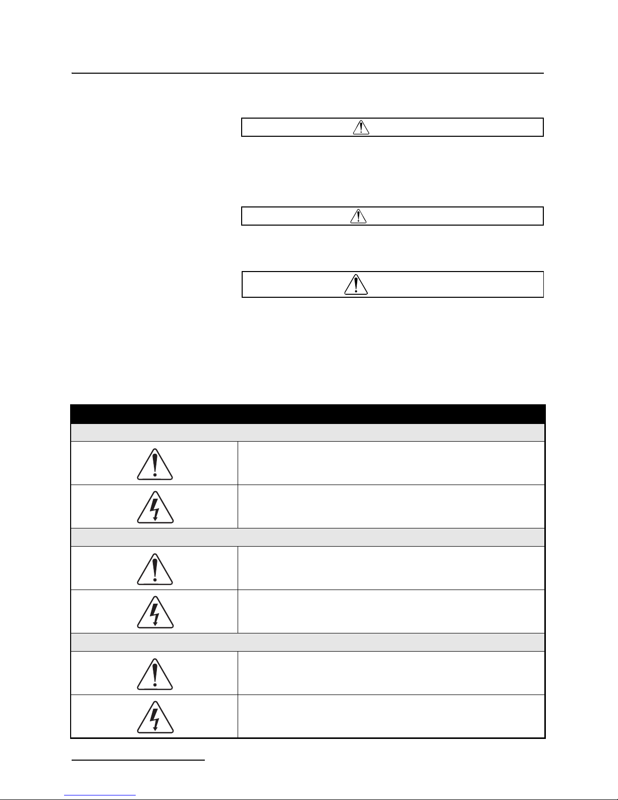
Hazard Severity Levels This manual applies Hazard Severity Levels to the safety alerts,
These three levels are described in the sample alerts below.
CAUTION
Cautions identify a potential hazard, which if not avoided, may
result in minor or moderate injury. This category can also warn
you of unsafe practices, or conditions that may cause property
damage.
WARNING
Warnings identify a potentially hazardous condition, which
if not avoided, could result in death or serious injury.
DANGER
DANGER – limited to the most extreme situations
to identify an imminent hazard, which if not
avoided, will result in death or serious injury.
Hazard Symbols The equipment and this manual use symbols used to warn of
hazards. The symbols are explained below.
Hazard Symbols
Warnings and Cautions
The exclamation point within the triangle is a warning sign alerting you of
important instructions in the instrument’s technical reference manual.
The lightning flash and arrowhead within the triangle is a warning sign alerting you of “dangerous voltage” inside the product.
Symboles de sécurité
Ce symbole signale l’existence d’instructions importantes relatives au
produit dans ce manuel.
Ce symbole signale la présence d’un danger d’électocution.
Warnungen und Vorsichtshinweise
iv
Das Ausrufezeichen in Dreieck ist ein Warnzeichen, das Sie darauf
aufmerksam macht, daß wichtige Anleitungen zu diesem Handbuch
gehören.
Der gepfeilte Blitz im Dreieck ist ein Warnzeichen, das Sei vor “gefährlichen
Spannungen” im Inneren des Produkts warnt.
Advertencias y Precauciones
Five-Station Battery Charger
Safety
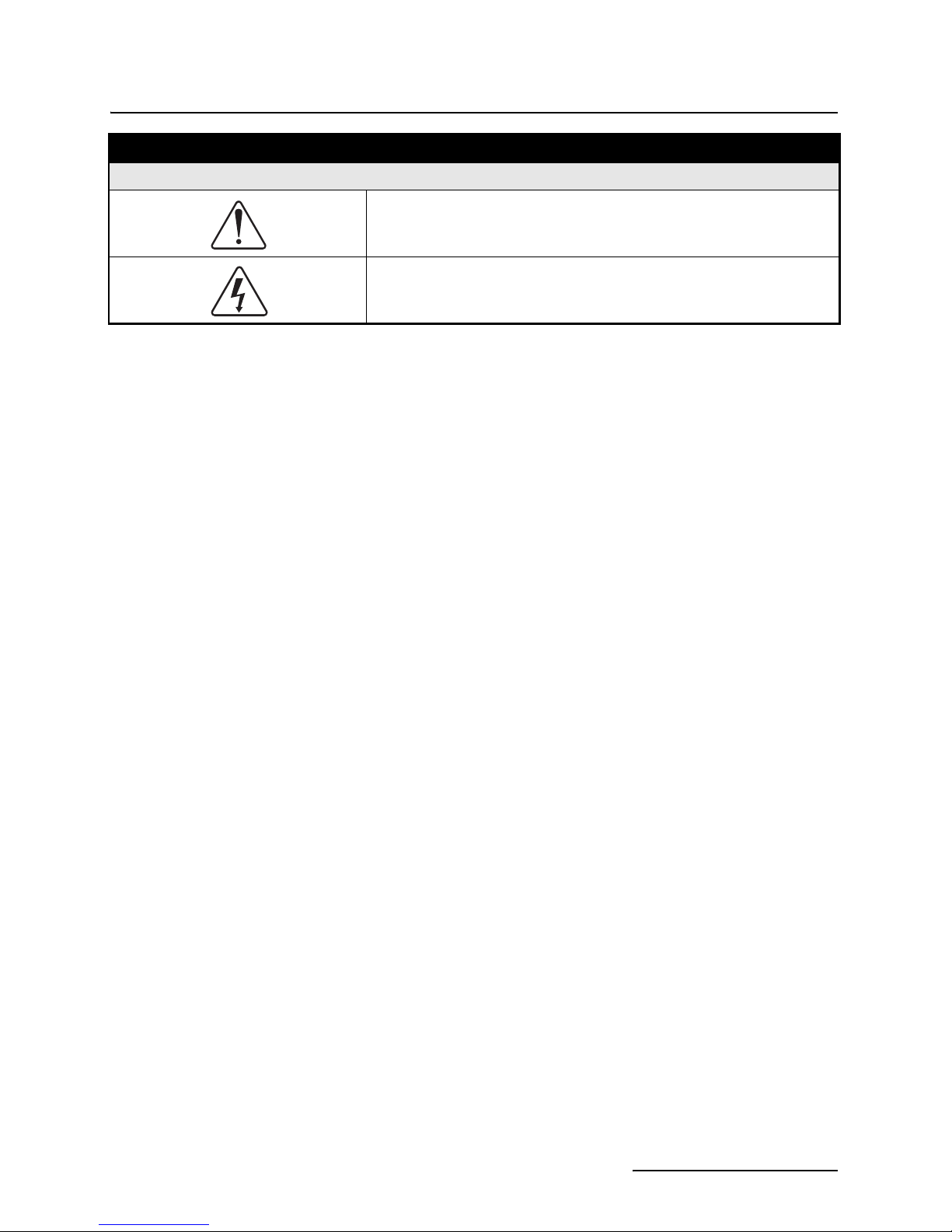
Hazard Symbols (Continued)
Esta señal le advierte sobre la importancia de las instrucciones del manual
que acompañan a este producto.
Esta señal alerta sobre la presencia de alto voltaje en el interior del
producto.
v

Five-Station Battery Charger
Safety
vi

965 Five-Station Battery Charger
1.1 Safety Instructions Save these instructions. These sheets contain important safety
and operating instructions for the Isco Model 965 Five-Station
Battery Charger.
1. Before using the charger read all of the instructions and
cautionary markings on (1) the Model 965 battery charger,
(2) the battery, and (3) the product using the battery.
WARNING
Charge only Isco 4 ampere-hour nickel-cadmium batteries
or Isco 6.5 ampere-hour lead-acid batteries. Other types of
batteries could vent or burst, resulting in personal injury or
property damage.
2. The Model 965 is for indoor use only. Do not expose the battery charger to rain or snow.
3. Use of attachments or appliances with this unit that are
not sold or recommended by Isco may result in the risk of
fire, electric shock, or personal injury.
4. To reduce the risk of damage to the Model 965 cord and
plug, always grasp the plug when disconnecting the unit,
rather than pulling on the cord.
5. When the Model 965 is in use, make sure the cord is
located so it will not be crushed, stepped on, tripped over,
or otherwise subjected to damage or stress.
6. Do not use an extension cord with the Model 965 charger
unless it is absolutely necessary. Use of an improper extension cord could result in the risk of fire or electric shock. If
you must use an extension cord, please make sure of the
following:
a. The pins on the extension cord plugs are the same size,
number, and shape as those of the plug on the charger.
b. The extension cord is properly wired and is in good
mechanical and electrical condition (no frayed wires or
exposed connections, and firm retention of the plug
when inserted).
c. The wire size of the extension cord is adequate for the
AC ampere rating of the charger as specified below:
Table 1-1 Recommended Wire Size For Extension Cord
Length of Cord - Feet 25 50 100 150 200
AWG Size of Cord (Min.) 18 18 18 16 16
1-1

965 Five-Station Battery Charger
7. Do not operate the charger with a damaged cord or plug.
Replace them immediately.
8. Do not operate the charger if it has been dropped, has
received a sharp blow, or has been otherwise damaged in
any way. Return the unit to Isco for proper repairs.
9. Do not disassemble the Model 965 charger unless you are
skilled in the diagnosis and repair of electronic circuitry.
Return it to Isco or take it to a qualified service person for
repair if this is needed. Improperly made repairs will void
the warranty, and could result in shock or fire hazard.
10. To reduce the risk of electric shock, disconnect the Model
965 charger from AC power before attempting any maintenance or cleaning. Turning off the controls will not reduce
this risk.
DANGER
Do not attempt to disassemble or troubleshoot
the Model 965 Five-Station Battery Charger
unless you are skilled in the diagnosis and repair
of electronic circuitry. Hazardous voltages are
present inside the charger and you could be killed
or seriously injured if you come in contact with
them. Refer all servicing to qualified personnel
only.
11. Make sure the VOLTAGE SELECTION switch on the rear
panel and the BATTERY SELECTION switch on the front
panel are properly set.
1-2

965 Five-Station Battery Charger
1.2 Technical
Specifications
Unit Weight 7.3 lb. (3.3 kg)
Dimensions 13.25 inches x 5 inches x 9.25 inches
Storage Temperature 40 to 140°F (5° to 60°C)
Humidity (Maximum) 95%
Maximum Altitude 2000 m
Installation Category II
Pollution Degree 2
is the disconnect device.)
Charging Temperature 32 to 113°F (0° to 45°C)
Charging Output
The table below contains the technical specifications for the
Model 965 Five-Station Battery Charger.
Table 1-2 Model 965 Technical Specifications
(33.7 x 12.7 x 23.5 cm)
User switched
104 - 127 VAC, 49 - 61 Hz, 1.2 Amp
Input Power (The line cord
Nickel-Cadmium
Lead-Acid
208 - 254 VAC, 49 - 61 Hz, 0.7 Amp
32 VDC max. open circuit voltage
0.4 Amp max. short circuit current
16 VDC max. open circuit voltage
0.8 Amp max. short circuit current
Battery Capacity
Nickel-Cadmium
Lead-Acid
Battery Recharge Time
Nickel-Cadmium
Lead-Acid
4 ampere-hour
6.5 ampere-hour
16 hours
16 hours
1-3

965 Five-Station Battery Charger
1.3 Front and Rear Panel
Controls and
Connections
2
1
Refer to the figures below and to Table 1-3 for the front and rear
controls and connections on the Model 965 Five-Station Battery
Charger.
3
Figure 1-1 Battery Charger Rear Panel
4
Fan louvers - allow 4 inches (10 cm) clearance for ventilation
DWG 60-3004-166
Figure 1-2 Battery Charger Front Panel
Table 1-1 Front and Rear Panel Controls/Connections
Item Function
1
Mains Input Power Connector
This is the disconnect device. Position the Model 965 so that either this connector or the mains
plug outlet is accessible in an emergency.
2
Mains Selector Switch
Before connecting the mains input power connector, make sure this is in the proper position for the
AC mains voltage you intend to connect to.
3
Circuit Breaker
This disconnects the power in the event of an internal component failure.
DWG 60-3004-166
5
1-4

Table 1-1 Front and Rear Panel Controls/Connections (Continued)
Item Function
4
This connects to both Isco-made nickel-cadmium and lead-acid batteries.
5
965 Five-Station Battery Charger
Connector for Charging Batteries
This switch must be in the proper position for the type of battery (nickel-cadmium or lead-acid).
NOTE: You cannot charge both battery types at once!
1.4 Grounding and AC
Power Connections
Battery Selector Switch
The Model 965 Five-Station Battery Charger should always be
grounded to reduce the risk of electrical shock. The charger has a
power cord with an equipment grounding conductor and a
three-pronged grounding plug. Attach this plug only to a
three-pronged outlet that is properly installed and grounded in
accordance with the National Electrical Code and all local codes
and ordinances.
WARNING
Before using the grounding adapter shown in Figure 1-3,
make sure the center screw of the outlet plate is grounded.
The green-colored rigid ear or lug extending from the
adapter must be connected to a properly grounded outlet.
Make certain it is grounded. If necessary, replace the
original outlet cover plate screw with a longer screw that
will secure the adapter ear or lug to the outlet cover plate
and make the ground connection to the grounded outlet.
The Model 965 Battery Charger is made for use on a nominal 120
or 240 volt 50-60 Hz AC circuit. The model supplied for use in
the U.S.A. and Canada has a 120-volt three-prong grounding
plug that looks like the plug shown to the left in Figure 1-3. A
temporary adapter can be used to connect this plug to a 2-pole
receptacle (as shown to the right in Figure 1-3) if a properly
grounded outlet is not available. The temporary adapter should
be used only until a properly grounded outlet can be installed by
a qualified electrician.
1-5

965 Five-Station Battery Charger
Three Prong
Grounding Plug
Three Prong
Grounding Plug
Grounding Pin
Figure 1-3 Grounding Methods
Grounding
Adapter
DWG 60-3003-020
Grounded Outlet
(3 Prongs)
Grounding Means
Metal Screw
Ungrounded Outlet
(2 Prongs)
Outlet Box Must
Be Grounded
DANGER
Never alter the AC cord or plug provided with the
unit, specifically by cutting off the third
grounding pin. If the plug will not fit into the
outlet, have the correct outlet installed by a
qualified electrician. If you fail to properly ground
the Model 965 charger, you risk electric shock.
You can verify grounding with an ordinary neon test light. Insert
one lead of the tester in the narrow or shorter (hot) slot of the
outlet. Put the other lead first into the wider (neutral) slot and
verify that the test lamp is glowing brightly. Then move this lead
from the wide slot (neutral) to the screw in the center of the
outlet plate. The test lamp should again glow brightly when you
touch the lead to the screw. If it does not, the screw (and probably
the rest of the circuit) is not grounded.
1-6

965 Five-Station Battery Charger
1.5 Operating
Instructions
The Model 965 Five-Station Battery Charger, when connected to
the appropriate AC power source, will properly charge either Isco
nickel-cadmium or lead-acid batteries. The charger provides a
regulated, current-limited 400 mA for the proper charging of
nickel-cadmium batteries, and a regulated voltage of 16 VDC
limited to 800 mA for charging lead-acid batteries.
Do not test either nickel-cadmium or lead-acid batteries for
state-of-charge by sparking the output (shorting the connectors
together). Be very careful inserting voltmeter probes into the
battery output connectors. Any accidents resulting in a shorted
battery output can damage the battery in less than three
seconds. Additionally, because the batteries are not internally
fused, the conductors from lead-acid batteries can weld together,
causing rapid heat buildup that may result in fire and serious
personal injury.
As many as five batteries of one type can be charged at the same
time with the Five-Station Battery Charger. To charge either
type of battery, simply attach the battery's connector to one of the
output connectors on the charger. Make certain the selector
switch is appropriate for the battery you are charging before
applying power. Generally the batteries (either type) will attain
full charge within 15 to 18 hours. Occasional or slight overcharging of the batteries will not hurt them, but it is worthwhile
to avoid frequent or prolonged overcharging.
Prolonged overcharging of nickel-cadmium batteries causes
internal heating of the cells. This heating will eventually make
the nylon separator material deteriorate between the plates,
causing shorts and hastening end-of-life for the cell. Prolonged
overcharging of lead-acid batteries forces the battery to vent
water from the electrolyte. The vents are one-way and the water
cannot be replaced. The battery will “dry out” and fail from lack
of electrolyte.
When charging more than one battery, the internal electronics
must be cooled by the internal fan. For adequate ventilation,
allow at least 4 inches (10 cm) of space between the rear panel of
the charger and a wall or other equipment.
1.6 Maintenance The Five-Station Battery Charger has a 1-ampere circuit breaker
mounted on the rear of the charger cabinet. If the circuit breaker
trips, you can reset it by pressing the button. If the circuit
breaker trips again quickly or repeatedly, there is probably something wrong with the electronic circuitry. Check to make sure the
VOLTAGE SELECTOR switch is in the proper position for the
power source you are using. Verify that the BATTERY
SELECTOR switch is in the proper position for the type of
battery you are charging. If the circuit breaker still continues to
trip after you have checked all these things, there may be an
internal problem.
For cleaning, use water with a small amount of detergent. For
harder to remove stains, use isopropyl alcohol.
1-7

965 Five-Station Battery Charger
1-8

Compliance Statements
ℶ❐₼㦘㹡㦘⹂䓸德㒥⏒侯䤓⚜䱿♙⚺摞
捷ↅ⚜䱿
Component Name
♧☚⣷
7UDQVIRUPHU
Name and amount of Hazardous Substances or Elements in the product
᳝↦᳝ᆇ⠽䋼ܗ㋴
Hazardous Substances or Elements
䪙
(Pb)
∲
(Hg)
䬝
(Cd)
݁Ӌ䫀
(Cr(VI))
⒈㘨㣃
(PBB)
X O O O X O
⒈Ѡ㘨㣃
(PBDE)
兎恾㨎
X O O O O O
&LUFXLW%RDUG
㘴⯃
O O X O O O
&RQQHFWRUV
䟄䄟兎
O O O O X O
/LQH&RUG
ℶ❐₼㦘㹡㦘⹂䓸德㒥⏒侯䤓⚜䱿♙⚺摞᧶Name and amount of Hazardous Substances or Elements in
the product
O: 嫷䯉年㦘㹡㦘⹂䓸德⦷年捷ↅ㓏㦘⧖德㧟㠨₼䤓⚺摞⧖⦷ST/ 㪖屓⸩䤓棟摞尐㻑ⅴₚᇭ
O: Represent the concentration of the hazardous substance in this component’s any homogeneous pieces is
lower than the ST/ standard limitation.
X᧶嫷䯉年㦘㹡㦘⹂䓸德咂⺠⦷年捷ↅ䤓㩟⧖德㧟㠨₼䤓⚺摞怔⒉ST/ 㪖屓⸩䤓棟摞尐㻑ᇭ
(←₩♾⦷㷳⮓᧨㫈㗽⸭棔㍔⑄⺈ₙ嫷₼㓢“X” 䤓㔏㦾☮⥯扪嫛扪㷴広㢝ᇭ)
X: Represent the concentration of the hazardous substance in this component’s at least one homogeneous
piece is higher than the ST/ standard limitation.
(Manufacturer may give technical reasons to the “X”marks)
䘾≬∎䞷㦮䟀兞洛䫽⸩ᇭ
The Environmentally Friendly Use Period (EFUP) was determined through experience.
䞮ℶ㡴㦮嬺冥䪐⦷侊⒦⚆䪐₼ᇭⓜₘ⇜㟿ⷦ䞮ℶ(207 ⅲ嫷 2007 ) ᇭ椞⚝䤓₹ⷦ㹜ⅲ嫷㦗᧶
A 㦗᧨B ℛ㦗᧨䷘䷘ᇭ
The date of Manufacture is in code within the serial number. The first three numbers are the year of
manufacture (207 is year 2007) followed by a letter for the month. "A" is January, "B" is February and so on.
Hazmat Table 923/924/965 60-3003-599 Rev.


DECLARATION OF CONFORMITY
Standards to which Conformity is Declared: EN 61326-1998 EMC Requirements for Electrical Equipment for
Standard Description Severity Applied Performance Criteria
EN61000-4-2 Electrostatic Discharge Level 2 - 4kV contact discharge
EN61000-4-3 Radiated RF Immunity 80 MHz to 1000MHz 80% AM at 1kHz
EN61000-4-4 Electrical Fast Transient Level 2 - 2kV on ac lines B
EN61000-4-5 Surge on AC Lines 2kV common mode, 1KV differential mode B
EN61000-4-6 Conducted RF on AC lines 150 kHz to 80 MHz,
EN61000-4-11 Voltage Dips/Short Interruptions 0.5 cycle, each polarity/100% B
CISPR11/
EN 55011
Application of Council Directive: 89/336/EEC – The EMC Directive
73/23/EEC – The Low Voltage Directive
Manufacturer's Name: Teledyne Isco, Inc.
Manufacturer's Address: 4700 Superior, Lincoln, Nebraska 68504 USA
Mailing Address: P.O. Box 82531, Lincoln, NE 68501
Equipment Type/Environment: Laboratory Equipment for Light Industrial/Commercial Environments
Trade Name/Model No: 965 Five Station Battery Charger
Year of Issue: 2001
Measurement, Control, and Laboratory Use
EN 61010-1 Safety Requirements for Measurement, control, and Laboratory
use.
rm
Level 3 - 8kV air discharge
f Confo
Level 1 - 10V/m
n o
ratio
la
c
De
3V rms, 80% modulated
CE
RF Emissions Group 1, Class A Industrial, Scientific, and
Medical Equipment
ity
B
B
A
B
EN61000-3-2, 3-3 Harmonic, Flicker
We, the undersigned, hereby declare that the design of the equipment specified above conforms to the above Directive(s) and
Standards as of March 6, 2001.
William Foster
USA Representative
William Foster
Director of Engineering
Teledyne Isco, Inc.
4700 Superior Street
Lincoln, Nebraska 68504
Phone: (402) 464-0231
Fax: (402) 464-4543
60-3002-019
Rev. A


Warran ty
Teledyne Isco One Year Limited Warranty*
Factory Service for Teledyne Isco Flow Meters, Waste Water Samplers, and Syringe Pumps
This warranty exclusively covers Teledyne Isco
instruments, providing a one-year limited warranty
covering parts and labor.
Any instrument that fails during the warranty period due to
faulty parts or workmanship will be repaired at the factory
at no charge to the customer. Teledyne Isco’s exclusive
liability is limited to repair or replacement of defective
instruments. Teledyne Isco is not liable for consequential
damages.
Teledyne Isco will pay surface transportation charges both
ways within the 48 contiguous United States if the
instrument proves to be defective within 30 days of
shipment. Throughout the remainder of the warranty period,
the customer will pay to return the instrument to Teledyne
Isco, and Teledyne isco will pay surface transportation to
return the repaired instrument to the customer. Teledyne
Isco will not pay air freight or customer’s packing and
crating charges. This warranty does not cover loss, damage,
or defects resulting from transportation between the
customer’s facility and the repair facility.
The warranty for any instrument is the one in effect on date
of shipment. The warranty period begins on the shipping
date, unless Teledyne Isco agrees in writing to a different
date.
Excluded from this warranty are normal wear; expendable
items such as charts, ribbon, lamps, tubing, and glassware;
fittings and wetted parts of valves; and damage due to
corrosion, misuse, accident, or lack of proper maintenance.
This warranty does not cover products not sold under the
Teledyne Isco trademark or for which any other warranty is
specifically stated.
No item may be returned for warranty service without a
return authorization number issued by Teledyne Isco.
This warranty is expressly in lieu of all other warranties
and obligations and Teledyne Isco specifically disclaims
any warranty of merchantability or fitness for a
particular purpose.
The warrantor is Teledyne Isco, Inc. 4700 Superior,
Lincoln, NE 68504, U.S.A.
* This warranty applies to the USA and countries where Teledyne Isco Inc. does not have an authorized
dealer. Customers in countries outside the USA, where Teledyne Isco has an authorized dealer, should
contact their Teledyne Isco dealer for warranty service.
Before returning any instrument for repair, please call, fax, or e-mail the Teledyne Isco Service
Department for instructions. Many problems can often be diagnosed and corrected over the
phone, or by e-mail, without returning the instrument to the factory.
Instruments needing factory repair should be packed carefully, and shipped to the attention of
the service department. Small, non-fragile items can be sent by insured parcel post. PLEASE
BE SURE TO ENCLOSE A NOTE EXPLAINING THE PROBLEM.
Shipping Address: Teledyne Isco, Inc. - Attention Repair Service
4700 Superior Street
Lincoln, NE 68504 USA
Mailing Address: Teledyne Isco, Inc.
PO Box 82531
Lincoln, NE 68501 USA
Phone: Repair service: (800) 775-2965 (lab instruments)
(866) 298-6174 (samplers & flow meters)
Sales & General Information: (800) 228-4373 (USA & Canada)
Fax: (402) 465-3001
Email: IscoService@teledyne.com
March 8, 2011 P/N 60-1002-040 Rev E

 Loading...