

Teledyne 9110TH User Manual
INSTRUCTION MANUAL
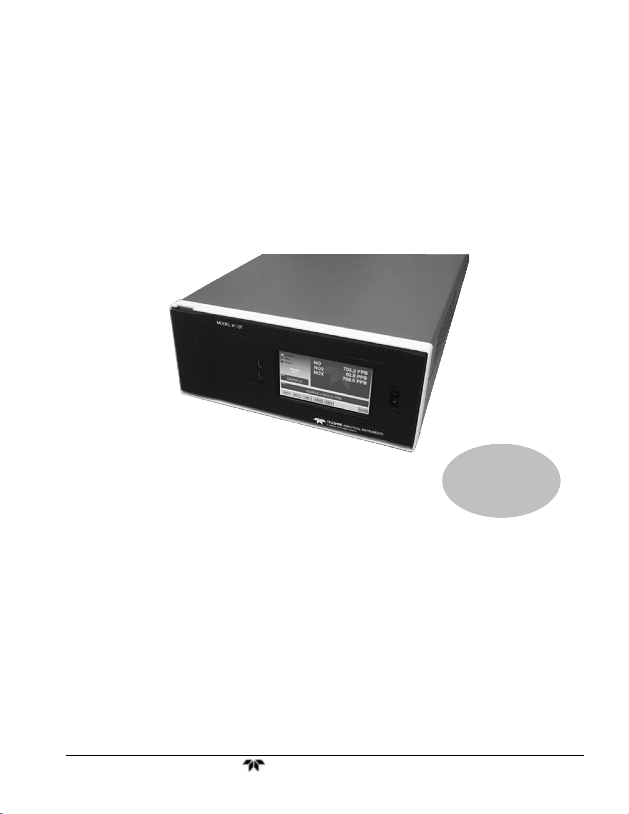
Model 9110TH
Nitrogen Oxides Analyzer
P/N M
DATE 10/11/13
TELEDYNE ELECTRONIC TECHNOLOGIES
Analytical Instruments
16830 Chestnut Street
City of Industry, CA 91748
Telephone: (626) 934-1500
Fax: (626) 961-2538
Web: www.teledyne-ai.com
Teledyne Analytical Instruments

Model 9110TH NOx Analyzer
Copyright © 2013 Teledyne Analytical Instruments
All Rights Reserved. No part of this manual may be reproduced, transmitted, transcribed, stored in a
retrieval system, or translated into any other language or computer language in whole or in part, in any
form or by any means, whether it be electronic, mechanical, magnetic, optical, manual, or otherwise,
without the prior written consent of Teledyne Analytical Instruments, 16830 Chestnut Street, City of
Industry, CA 91748.
Warranty
This equipment is sold subject to the mutual agreement that it is warranted by us free from defects of
material and of construction, and that our liability shall be limited to replacing or repairing at our
factory (without charge, except for transportation), or at customer plant at our option, any material or
construction in which defects become apparent within one year from the date of shipment, except in
cases where quotations or acknowledgements provide for a shorter period. Components manufactured
by others bear the warranty of their manufacturer. This warranty does not cover defects caused by wear,
accident, misuse, neglect or repairs other than those performed by Teledyne or an authorized service
center. We assume no liability for direct or indirect damages of any kind and the purchaser by the
acceptance of the equipment will assume all liability for any damage which may result from its use or
misuse.
We reserve the right to employ any suitable material in the manufacture of our apparatus, and to make
any alterations in the dimensions, shape or weight of any parts, in so far as such alterations do not
adversely affect our warranty.
Important Notice
This instrument provides measurement readings to its user, and serves as a tool by which valuable data can
be gathered. The information provided by the instrument may assist the user in eliminating potential
hazards caused by his process; however, it is essential that all personnel involved in the use of the
instrument or its interface be properly trained in the process being measured, as well as all instrumentation
related to it.
The safety of personnel is ultimately the responsibility of those who control process conditions. While
this instrument may be able to provide early warning of imminent danger, it has no control over process
conditions, and it can be misused. In particular, any alarm or control systems installed must be tested
and understood, both as to how they operate and as to how they can be defeated. Any safeguards
required such as locks, labels, or redundancy, must be provided by the user or specifically requested of
Teledyne at the time the order is placed.
Therefore, the purchaser must be aware of the hazardous process conditions. The purchaser is
responsible for the training of personnel, for providing hazard warning methods and instrumentation per
the appropriate standards, and for ensuring that hazard warning devices and instrumentation are
maintained and operated properly.
Teledyne Analytical Instruments, the manufacturer of this instrument, cannot accept responsibility for
conditions beyond its knowledge and control. No statement expressed or implied by this document or
any information disseminated by the manufacturer or its agents, is to be construed as a warranty of
adequate safety control under the user’s process conditions.
Trademarks
All trademarks, registered trademarks, brand names or product names appearing in this document are
the property of their respective owners and are used herein for identification purposes only.
Teledyne Analytical Instruments ii

Model 9110TH NOx Analyzer
INFORMATION ABOUT THE SPECIFIC CONFIGURATION OF YOUR
MODEL 9110T NOX ANALYZER
Note: All instruments must include the standard hardcopy manual.
SELECTED VERSIONS OF THE MODEL 9110T
Model 9110T— Standard Touch Screen Version
This Model 9110E NOx Analyzer is a touch screen version designed for analyzing the NOx
concentration in a background gas specified by the customer. It has a minimum settable range of
0-50 ppb and a maximum settable range of 0-10 ppm. The standard version is designed for
ambient pressure applications. The analyzer may have one or two analysis ranges with or without
auto-ranging as listed below. It includes an internal Moly converter and an external pump. Alarm
relays are optional and if included, that option will be checked below.
Model 9110TH — High Range Touch Screen Version
The Model 9110EH NOx Analyzer is a touch screen version designed for analyzing higher NOx
concentration (from 0-5 ppm to 0-5000 ppm) than the standard model. It includes an internal
Hicon converter and an external pump. Alarm relays are optional and if included, that option will
be checked below. There is no internal zero/span gas/oven option available for this model. The
analyzer may have one or two analysis ranges with or without autoranging as listed below.
This version is available with internal or external Hicon or Moly converters.
Model 9110TM — Mid-Range Touch Screen Version
The Model 9110EA NOx Analyzer is a touch screen version designed for analyzing a mid-range
NO
concentration. It has a minimum settable range of 0-1 ppm and a maximum settable range of
x
0-200 ppm. t includes an internal Moly converter and an external pump. Alarm relays are optional
and if included, that option will be checked below. There is no internal zero/span gas/oven
option available for this model. The analyzer may have one or two analysis ranges with or
without autoranging as listed below.
This model is similar to the EH version but does not have a sample bypass line. An optional
paramagnetic oxygen sensor is available for oxygen analysis in this version.
Converter Options
The 9110 is equipped with an internal Hicon thermal converter as standard equipment.
Other converters are available for the EH version as follows:
Internal Hicon (standard) External Hicon (2
Internal Moly External Moly (2
nd
set of rack mounts req’d)
nd
set of rack mounts req’d)
Teledyne Analytical Instruments iii
Model 9110TH NOx Analyzer
Power Requirements
This Model 9110E is configured to operate from the following AC Power source:
100-120 VAC 60 Hz 220-240 VAC 60 Hz 100V 60 Hz
100-120 VAC 50 Hz 220-240 VAC 50 Hz 100V 50 Hz
Analog Output Signals
Analog output signals are available at A1, A2, and A3 on the rear panel. This instrument is
configured with the following analog outputs:
A1(NOx): 4-20 mA
A2 (NO): 0-5 V A2(NO): 4-20 mA
A3 (NO
): 0-5 V A2(NO2): 4-20 mA
2
Range Mode
The analyzer can be designed with a single or dual analysis ranges with auto-ranging or dual
independent ranges. This analyzer is configured with the following range mode:
Single Range:
Dual Range/Auto-ranging:
Low Range: Low Range:
High Range: High Range:
Dual Range/Independent:
Gas:
Selected Options for the Model 9110T
Mounting Options
19” rack mounting with 26” sliders with ears
19” rack mounting with ears only
Pump Mounting Options
None
Rack mounting hardware
Rear Panel Gas Fittings
1/4” SS Standard
6 mm SS Optional
Teledyne Analytical Instruments iv

Model 9110TH NOx Analyzer
Valve Options
No Valves
Internal SS Zero/Span Valves
Second Range Span Valve
Internal Zero/Span Valves with Oven (Not available for 9110EH/EM)
Internal Zero/Span Valves with Oven and Permeation Tube (Not available for
9110EH)
The permeation tube option installed depends on the sample gas and the
effusion rate. The specific permeation tube in this instrument is listed below:
Permeation tube Installed:
Alarm Relay Option
This option includes two concentration alarm relays.
Oxygen Sensor
This analyzer is equipped with a paramagnetic oxygen sensor for measuring the oxygen
concentration over the range of 0-25%
Gas Conditioner
A gas conditioner/dryer permeation gas exchange tube is installed for removing H2O and
ammonia from the sample stream. This item is required for EN certificatation.
Oxygenator
For applications where background gas less than 2% oxygen and using a Moly converter.
Remote Operation for Purged Enclosure
The operator interface is duplicated with switches mounted on the front door of the enclosure
allowing operation without compromising purge integrity.
Background Gas:
Notes:
Teledyne Analytical Instruments v

Model 9110TH NOx Analyzer
This page intentionally left blank.
Teledyne Analytical Instruments vi
Model 9110TH NOx Analyzer Safety Messages
SAFETY MESSAGES
Important safety messages are provided throughout this manual for the purpose of
avoiding personal injury or instrument damage. Please read these messages carefully.
Each safety message is associated with a safety alert symbol, and are placed
throughout this manual; the safety symbols are also located inside the instrument. It is
imperative that you pay close attention to these messages, the descriptions of which
are as follows:
WARNING: Electrical Shock Hazard
HAZARD: Strong oxidizer
GENERAL WARNING/CAUTION: Read the accompanying message for
specific information.
CAUTION: Hot Surface Warning
Do Not Touch: Touching some parts of the instrument without
protection or proper tools could result in damage to the part(s) and/or the
instrument.
Technician Symbol: All operations marked with this symbol are to be
This instrument should only be used for the purpose and in the manner described
in this manual. If you use this instrument in a manner other than that for which it
was intended, unpredictable behavior could ensue with possible hazardous
consequences.
performed by qualified maintenance personnel only.
Electrical Ground: This symbol inside the instrument marks the central
safety grounding point for the instrument.
CAUTION
NEVER use any gas analyzer to sample combustible gas(es)!
Note: Technical Assistance regarding the use and maintenance of the Model 9110TH or any
other Teledyne product can be obtained by contacting Teledyne Customer Service
Department:
Phone: 888-789-8168
Email: ask_tai@teledyne.com
or by accessing various service options on our website at
http://www.teledyne-ai.com/
Teledyne Analytical Instruments vii
Model 9110TH NOx Analyzer Safety Messages
CONSIGNES DE SÉCURITÉ
Des consignes de sécurité importantes sont fournies tout au long du présent manuel
dans le but d’éviter des blessures corporelles ou d’endommager les instruments.
Veuillez lire attentivement ces consignes. Chaque consigne de sécurité est
représentée par un pictogramme d’alerte de sécurité; ces pictogrammes se retrouvent
dans ce manuel et à l’intérieur des instruments. Les symboles correspondent aux
consignes suivantes :
AVERTISSEMENT : Risque de choc électrique
DANGER : Oxydant puissant
AVERTISSEMENT GÉNÉRAL / MISE EN GARDE : Lire la consigne
complémentaire pour des renseignements spécifiques
MISE EN GARDE : Surface chaude
Ne pas toucher : Toucher à certaines parties de l’instrument sans protection ou
sans les outils appropriés pourrait entraîner des dommages aux pièces ou à
l’instrument.
Pictogramme « technicien » : Toutes les opérations portant ce symbole doivent
être effectuées uniquement par du personnel de maintenance qualifié.
Mise à la terre : Ce symbole à l’intérieur de l’instrument détermine le point central
de la mise à la terre sécuritaire de l’instrument.
MISE EN GARDE
Cet instrument doit être utilisé aux fins décrites et de la manière décrite dans
ce manuel. Si vous utilisez cet instrument d’une autre manière que celle pour
laquelle il a été prévu, l’instrument pourrait se comporter de façon imprévisible
et entraîner des conséquences dangereuses.
NE JAMAIS utiliser un analyseur de gaz pour échantillonner des gaz
combustibles!
Teledyne Analytical Instruments viii

Model 9110TH NOx Analyzer Safety Messages
This page intentionally left blank.
Teledyne Analytical Instruments ix


Manual Information Model 9110TH NOx Analyzer
ABOUT THIS MANUAL
This manual describes operation, specifications, and maintenance for the Model 9110TH.
In addition this manual contains important SAFETY messages for this instrument. It is strongly
recommended that you read that operation manual in its entirety before operating the instrument.
Teledyne Analytical Instruments xi

Model 9110TH NOx Analyzer Manual Information
This page intentionally left blank.
Teledyne Analytical Instruments xii

Table of Contents Model 9110TH NOx Analyzer
TABLE OF CONTENTS
Information About the Specific Configuration of Your Model 9110E NOX Analyzer ...................................................................iii
Selected Versions of the Model 9110T .......................................................................................................................................iii
Mounting Options .............................................................................................................................................................. iv
Pump Mounting Options .................................................................................................................................................... iv
Rear Panel Gas Fittings.................................................................................................................................................... iv
SAFETY MESSAGES .................................................................................................................................................................vii
CONSIGNES DE SÉCURITÉ..................................................................................................................................................... viii
About This Manual ...................................................................................................................................................................... xi
Table of Contents ....................................................................................................................................................................... xiii
List of Figures............................................................................................................................................................................. xvi
List of Tables ............................................................................................................................................................................ xviii
LIST OF APPENDICES ............................................................................................................................................................. xix
1. Introduction, Features, and Options ......................................................................................................................................... 1
1.1. Overview .......................................................................................................................................................................... 1
1.2. Features ........................................................................................................................................................................... 1
1.3. Using This Manual ............................................................................................................................................................ 1
1.4. Options ............................................................................................................................................................................. 2
2. Specifications and Approvals ................................................................................................................................................... 5
2.1. 9110TH/M Operating Specifications ................................................................................................................................. 5
2.2. Approvals and Certifications ............................................................................................................................................. 6
2.2.1. Safety ....................................................................................................................................................................... 6
2.2.2. EMC .......................................................................................................................................................................... 6
3. Getting Started ......................................................................................................................................................................... 7
3.1. Unpacking and Initial Setup .............................................................................................................................................. 7
3.2. Ventilation Clearance ....................................................................................................................................................... 8
3.3. 9110TH/M Layout ............................................................................................................................................................. 8
3.4. Electrical Connections .................................................................................................................................................... 14
3.4.1. Power Connection .................................................................................................................................................. 14
3.4.2. Analog Inputs (Option 64) Connections .................................................................................................................. 15
3.4.3. Analog Output Connections .................................................................................................................................... 15
3.4.4. Connecting the Status Outputs ............................................................................................................................... 16
3.4.5. Current Loop Analog Outputs (OPT 41) Setup ....................................................................................................... 18
3.4.6. Connecting the Control Inputs ................................................................................................................................ 20
3.4.7. Connecting the Alarm Relay Option (OPT 61) ........................................................................................................ 21
3.4.8. Connecting the Communications Ports ................................................................................................................... 22
3.5. Pneumatic Connections ................................................................................................................................................. 24
3.5.1. About Zero Air and Calibration (Span) Gases ........................................................................................................ 24
3.5.2. Pneumatic Connections to 9110TH/M Basic Configuration .................................................................................... 26
3.5.3. Connections with Internal Valve Options Installed .................................................................................................. 31
3.6. Initial Operation .............................................................................................................................................................. 41
3.6.1. Startup .................................................................................................................................................................... 41
3.6.2. Warning Messages ................................................................................................................................................. 41
3.6.3. Functional Check .................................................................................................................................................... 42
3.7. Calibration ...................................................................................................................................................................... 43
3.7.1. Basic NOx Calibration Procedure ............................................................................................................................ 43
3.7.2. Basic O2 Sensor Calibration Procedure .................................................................................................................. 48
4. Operating Instructions ............................................................................................................................................................ 53
4.1. Overview of Operating Modes ........................................................................................................................................ 53
4.2. Sample Mode ................................................................................................................................................................. 54
4.2.1. Test Functions ........................................................................................................................................................ 54
4.2.2. Warning Messages ................................................................................................................................................. 56
4.3. Calibration Mode ............................................................................................................................................................ 58
4.3.1. Calibration Functions .............................................................................................................................................. 58
4.4. SETUP MODE ................................................................................................................................................................ 58
4.5. SETUP CFG: Viewing the Analyzer’s Configuration Information ............................................................................... 59
4.6. SETUP ACAL: Automatic Calibration ......................................................................................................................... 60
4.7. SETUP DAS - Using the Data Acquisition System (DAS) ......................................................................................... 61
4.7.1. DAS Structure ......................................................................................................................................................... 62
4.7.2. Default DAS Channels ............................................................................................................................................ 64
4.7.3. Remote DAS Configuration .................................................................................................................................... 79
4.8. SETUP RNGE: Range Units and Dilution Configuration ............................................................................................ 80
Teledyne Analytical Instruments xiii

Model 9110TH NOx Analyzer Table of Contents
4.8.1. Range Units ............................................................................................................................................................ 80
4.8.2. Dilution Ratio .......................................................................................................................................................... 81
4.9. SETUP PASS: Password Feature ............................................................................................................................. 82
4.10. SETUP CLK: Setting the Internal Time-of-Day Clock .............................................................................................. 84
4.11. SETUP MORE COMM: Setting Up the Analyser’s Communication Ports ........................................................... 86
4.11.1. DTE and DCE Communication ............................................................................................................................. 86
4.11.2. COM Port Default Settings ................................................................................................................................... 86
4.11.3. Communication Modes, Baud Rate and Port Testing ........................................................................................... 87
4.11.4. Analyzer ID ........................................................................................................................................................... 91
4.11.5. RS-232 COM Port Cable Connections ................................................................................................................. 92
4.11.6. RS-485 Configuration of COM2 ............................................................................................................................ 94
4.11.7. Ethernet Interface Configuration ........................................................................................................................... 94
4.11.8. USB Port Setup .................................................................................................................................................. 100
4.11.9. Multidrop RS-232 Set Up .................................................................................................................................... 102
4.11.10. MODBUS SETUP ............................................................................................................................................. 105
4.12. SETUP MORE VARS: Internal Variables (VARS) ............................................................................................. 107
4.12.1. Setting the Gas Measurement Mode .................................................................................................................. 109
4.13. SETUP MORE DIAG: Diagnostics MENU ........................................................................................................ 110
4.13.1. Accessing the Diagnostic Features..................................................................................................................... 111
4.13.2. Signal I/O ............................................................................................................................................................ 111
4.13.3. Analog Output Step Test .................................................................................................................................... 113
4.13.4. ANALOG OUTPUTS and Reporting Ranges ...................................................................................................... 114
4.13.5. ANALOG I/O CONFIGURATION ........................................................................................................................ 117
4.13.6. ANALOG OUTPUT CALIBRATION .................................................................................................................... 131
4.13.7. Other DIAG Menu Functions .............................................................................................................................. 140
4.14. SETUP – ALRM: Using the Optional Gas Concentration Alarms (OPT 67) ................................................................ 148
4.15. Remote Operation ...................................................................................................................................................... 149
4.15.1. Remote Operation Using the External Digital I/O ............................................................................................... 149
4.15.2. Remote Operation .............................................................................................................................................. 151
4.15.3. Additional Communications Documentation ....................................................................................................... 158
4.15.4. Using the 9110TH/M with a Hessen Protocol Network ....................................................................................... 158
5. Calibration Procedures ......................................................................................................................................................... 165
5.1.1. Interferents for NOX Measurements ...................................................................................................................... 165
5.2. Calibration Preparations ............................................................................................................................................... 166
5.2.1. Required Equipment, Supplies, and Expendables ................................................................................................ 166
5.2.2. Zero Air ................................................................................................................................................................. 166
5.2.3. Span Calibration Gas Standards & Traceability .................................................................................................... 167
5.2.4. Data Recording Devices ....................................................................................................................................... 168
5.2.5. NO2 Conversion Efficiency (CE) ........................................................................................................................... 168
5.3. Manual Calibration ....................................................................................................................................................... 173
5.4. Calibration Checks ....................................................................................................................................................... 177
5.5. Manual Calibration with Zero/Span Valves ................................................................................................................... 178
5.6. Calibration Checks with Zero/Span Valves ................................................................................................................... 181
5.7. Calibration With Remote Contact Closures .................................................................................................................. 182
5.8. Automatic Calibration (AutoCal) ................................................................................................................................... 183
5.9. Calibration Quality Analysis .......................................................................................................................................... 186
6. Instrument Maintenance ....................................................................................................................................................... 187
6.1. Maintenance Schedule ................................................................................................................................................. 187
6.2. ...................................................................................................................................................................................... 189
6.3. Predictive Diagnostics .................................................................................................................................................. 191
6.4. Maintenance Procedures .............................................................................................................................................. 191
6.4.1. Changing the Sample Particulate Filter ................................................................................................................ 191
6.4.2. Changing the O3 Dryer Particulate Filter ............................................................................................................... 193
6.4.3. Maintaining the External Sample Pump ................................................................................................................ 194
6.4.4. Changing the NO2 Converter ................................................................................................................................ 195
6.4.5. Cleaning the Reaction Cell ................................................................................................................................... 196
6.4.6. Changing Critical Flow Orifices ............................................................................................................................. 198
6.4.7. Checking for Light Leaks ...................................................................................................................................... 199
7. Troubleshooting & Repair .................................................................................................................................................... 201
7.1. General Troubleshooting .............................................................................................................................................. 201
7.1.1. Fault Diagnosis with Warning Messages .............................................................................................................. 202
7.1.2. Fault Diagnosis with Test Functions ..................................................................................................................... 204
7.1.3. Using the Diagnostic Signal I/O Function ............................................................................................................. 205
7.1.4. Status LED’s ......................................................................................................................................................... 207
7.2. Gas Flow Problems ...................................................................................................................................................... 210
Teledyne Analytical Instruments xiv

Table of Contents Model 9110TH NOx Analyzer
7.2.1. 9110TH Internal Gas Flow Diagrams .................................................................................................................... 211
7.2.2. 9110TM Internal Gas Flow Diagrams ................................................................................................................... 214
7.2.3. Zero or Low Flow Problems .................................................................................................................................. 216
7.2.4. High Flow .............................................................................................................................................................. 218
7.2.5. Sample Flow is Zero or Low But Analyzer Reports Correct Flow ......................................................................... 219
7.3. Calibration Problems .................................................................................................................................................... 219
7.3.1. Negative Concentrations ...................................................................................................................................... 219
7.3.2. No Response ........................................................................................................................................................ 220
7.3.3. Unstable Zero and Span ....................................................................................................................................... 221
7.3.4. Inability to Span - No SPAN Button ...................................................................................................................... 221
7.3.5. Inability to Zero - No ZERO Button ....................................................................................................................... 222
7.3.6. Non-Linear Response ........................................................................................................................................... 222
7.3.7. Discrepancy Between Analog Output and Display ............................................................................................... 223
7.3.8. Discrepancy between NO and NOX Slopes .......................................................................................................... 223
7.4. Other Performance Problems ....................................................................................................................................... 224
7.4.1. Excessive Noise ................................................................................................................................................... 224
7.4.2. Slow Response ..................................................................................................................................................... 224
7.4.3. Auto Zero Warnings .............................................................................................................................................. 225
7.5. Subsystem Checkout ................................................................................................................................................... 226
7.5.1. Simple Leak Check using Vacuum and Pump ...................................................................................................... 226
7.5.2. Detailed Leak Check Using Pressure ................................................................................................................... 226
7.5.3. Performing a Sample Flow Check ........................................................................................................................ 227
7.5.4. AC Power Configuration ....................................................................................................................................... 228
7.5.5. DC Power Supply Test Points .............................................................................................................................. 233
7.5.6. I2C Bus ................................................................................................................................................................. 233
7.5.7. Touch Screen Interface ........................................................................................................................................ 234
7.5.8. LCD Display Module ............................................................................................................................................. 234
7.5.9. General Relay Board Diagnostics ......................................................................................................................... 234
7.5.10. Motherboard ....................................................................................................................................................... 235
7.5.11. CPU .................................................................................................................................................................... 237
7.5.12. RS-232 Communication ...................................................................................................................................... 238
7.5.13. PMT Sensor ........................................................................................................................................................ 239
7.5.14. PMT Preamplifier Board ..................................................................................................................................... 239
7.5.15. High Voltage Power Supply ................................................................................................................................ 239
7.5.16. Pneumatic Sensor Assembly .............................................................................................................................. 240
7.5.17. NO2 Converter .................................................................................................................................................... 241
7.5.18. O3 Generator ...................................................................................................................................................... 243
7.5.19. Box Temperature ................................................................................................................................................ 243
7.5.20. PMT Temperature ............................................................................................................................................... 244
7.6. Repair Procedures ....................................................................................................................................................... 245
7.6.1. Disk-on-Module Replacement .............................................................................................................................. 245
7.6.2. O3 Generator Replacement .................................................................................................................................. 246
7.6.3. Sample and Ozone Dryer Replacement ............................................................................................................... 246
7.6.4. PMT Sensor Hardware Calibration ....................................................................................................................... 247
7.6.5. Replacing the PMT, HVPS or TEC ....................................................................................................................... 249
7.7. Removing / Replacing the Relay PCA from the Instrument .......................................................................................... 252
7.8. Frequently Asked Questions ........................................................................................................................................ 253
7.9. Technical Assistance .................................................................................................................................................... 254
8. Principles of Operation ......................................................................................................................................................... 256
8.1. Measurement Principle ................................................................................................................................................. 256
8.1.1. Chemiluminescence ............................................................................................................................................. 256
8.1.2. NOX and NO2 Determination ................................................................................................................................. 258
8.2. Chemiluminescence Detection ..................................................................................................................................... 259
8.2.1. The Photo Multiplier Tube ..................................................................................................................................... 259
8.2.2. Optical Filter ......................................................................................................................................................... 259
8.2.3. Auto Zero .............................................................................................................................................................. 260
8.2.4. Measurement Interferences .................................................................................................................................. 261
8.3. Pneumatic Operation .................................................................................................................................................... 263
8.3.1. Pump and Exhaust Manifold ................................................................................................................................. 263
8.3.2. Sample Gas Flow ................................................................................................................................................. 264
8.3.3. Flow Rate Control - Critical Flow Orifices ............................................................................................................. 265
8.3.4. Sample Particulate Filter ....................................................................................................................................... 269
8.3.5. Ozone Gas Air Flow .............................................................................................................................................. 270
8.3.6. O3 Generator ........................................................................................................................................................ 271
8.3.7. Perma Pure® Dryer ............................................................................................................................................... 272
Teledyne Analytical Instruments xv

Model 9110TH NOx Analyzer Table of Contents
8.3.8. Ozone Supply Air Filter ......................................................................................................................................... 274
8.3.9. Ozone Scrubber ................................................................................................................................................... 274
8.3.10. Pneumatic Sensors ............................................................................................................................................. 275
8.3.11. Dilution Manifold ................................................................................................................................................. 276
8.4. Oxygen Sensor (OPT 65A) Principles of Operation ..................................................................................................... 277
8.4.1. Paramagnetic Measurement of O2 ........................................................................................................................ 277
8.4.2. Operation Within the 9110TH/M Analyzer ............................................................................................................ 278
8.4.3. Pneumatic Operation of the O2 Sensor ................................................................................................................. 278
8.5. Electronic Operation ..................................................................................................................................................... 279
8.5.1. CPU ...................................................................................................................................................................... 280
8.5.2. Sensor Module, Reaction Cell .............................................................................................................................. 281
8.5.3. Photo Multiplier Tube (PMT) ................................................................................................................................. 282
8.5.4. PMT Cooling System ............................................................................................................................................ 284
8.5.5. PMT Preamplifier .................................................................................................................................................. 284
8.5.6. Pneumatic Sensor Board ...................................................................................................................................... 286
8.5.7. Relay Board .......................................................................................................................................................... 286
8.5.8. Status LEDs & Watch Dog Circuitry...................................................................................................................... 290
8.5.9. Motherboard ......................................................................................................................................................... 291
8.5.10. Analog Outputs ................................................................................................................................................... 293
8.5.11. External Digital I/O .............................................................................................................................................. 293
8.5.12. I2C Data Bus ....................................................................................................................................................... 293
8.5.13. Power-up Circuit ................................................................................................................................................. 293
8.6. Power Distribution & Circuit Breaker ............................................................................................................................ 294
8.7. Front Panel/Display Interface Electronics ..................................................................................................................... 295
8.7.1. Front Panel Interface PCA .................................................................................................................................... 295
8.8. Software Operation ...................................................................................................................................................... 296
8.8.1. Adaptive Filter ....................................................................................................................................................... 297
8.8.2. Calibration - Slope and Offset ............................................................................................................................... 297
8.8.3. Temperature/Pressure Compensation (TPC) ....................................................................................................... 298
8.8.4. NO2 Converter Efficiency Compensation .............................................................................................................. 299
8.8.5. Internal Data Acquisition System (DAS) ............................................................................................................... 299
9. A Primer on Electro-Static Discharge ................................................................................................................................... 301
9.1. How Static Charges are Created .................................................................................................................................. 301
9.2. How Electro-Static Charges Cause Damage ................................................................................................................ 302
9.3. Common Myths About ESD Damage ........................................................................................................................... 303
9.4. Basic Principles of Static Control .................................................................................................................................. 304
9.4.1. General Rules ....................................................................................................................................................... 304
9.4.2. Basic anti-ESD Procedures for Analyzer Repair and Maintenance ...................................................................... 305
Glossary ................................................................................................................................................................................... 311
LIST OF FIGURES
Figure 3-1: Front Panel .................................................................................................................................... 9
Figure 3-2: Display Screen and Touch Control ................................................................................................ 9
Figure 3-3: Display/Touch Control Screen Mapped to Menu Charts ............................................................. 11
Figure 3-4: 9110TH/M Rear Panel Layout ..................................................................................................... 12
Figure 3-5: 9110TH/M Internal Layout ........................................................................................................... 13
Figure 3-6: Analog In Connector .................................................................................................................... 15
Figure 3-7: Analog Output Connector ............................................................................................................ 16
Figure 3-8: Status Output Connector ............................................................................................................. 17
Figure 3-9: Current Loop Option Installed on the Motherboard ..................................................................... 18
Figure 3-10: Control Input Connector ............................................................................................................... 20
Figure 3-11: Alarm Relay Output Pin Assignments .......................................................................................... 21
Figure 3-12: 9110TH/M Multidrop Card ........................................................................................................... 23
Figure 3-13: Pneumatic Connections–Basic Configuration–Using Gas Dilution Calibrator ............................. 26
Figure 3-14: Pneumatic Connections–Basic Configuration–Using Bottled Span Gas ..................................... 27
Figure 3-15: 9110TH Internal Pneumatic Block Diagram - Standard Configuration ........................................ 29
Figure 3-16: 9110TM Internal Pneumatic Block Diagram - Standard Configuration ........................................ 30
Figure 3-17: Pneumatic Connections–With Zero/Span Valve Option (50A) .................................................... 31
Figure 3-18: Pneumatic Connections–With 2-Span point Option (50D) –Using Bottled Span Gas ................. 31
Teledyne Analytical Instruments xvi

Table of Contents Model 9110TH NOx Analyzer
Figure 3-19: 9110TH – Internal Pneumatics with Ambient Zero-Span Valve Option 50A ............................... 32
Figure 3-20: 9110TM – Internal Pneumatics with Ambient Zero-Span Valve Option 50A ............................... 33
Figure 3-21: 9110TH - Internal Pneumatics for Zero Scrubber/Dual Pressurized Span, Option 50D ............. 37
Figure 3-22: 9110TM - Internal Pneumatics for Zero Scrubber/Dual Pressurized Span, Option 50D ............. 38
Figure 3-23: 9110TH – Internal Pneumatics with O2 Sensor Option 65A ....................................................... 39
Figure 3-24: 9110TM – Internal Pneumatics with O2 Sensor Option 65A ........................................................ 40
Figure 3-23: O2 Sensor Calibration Set Up ...................................................................................................... 48
Figure 4-1: Front Panel Display with “SAMPLE” Indicated in the Mode Field ............................................... 53
Figure 4-2: Viewing 9110TH/M TEST Functions ............................................................................................ 56
Figure 4-3: Viewing and Clearing 9110TH/M WARNING Messages ............................................................. 57
Figure 4-4: APICOM Graphical User Interface for Configuring the DAS ....................................................... 79
Figure 4-5: Default Pin Assignments for Rear Panel com Port Connectors (RS-232 DCE & DTE) .............. 92
Figure 4-6: CPU COM1 & COM2 Connector Pin-Outs in RS-232 mode. ...................................................... 93
Figure 4-7: COM – LAN / Internet Manual Configuration ............................................................................... 98
Figure 4-8: Jumper and Cables for Multidrop Mode.....................................................................................103
Figure 4-9: RS-232-Multidrop Host-to-Analyzer Interconnect Diagram .......................................................104
Figure 4-10: Analog Output Connector Key ...................................................................................................114
Figure 4-11: Setup for Calibrating Analog Outputs ........................................................................................134
Figure 4-12: Setup for Calibrating Current Outputs .......................................................................................136
Figure 4-13: Alternative Setup for Calibrating Current Outputs .....................................................................136
Figure 4-14. DIAG – Analog Inputs (Option) Configuration Menu .................................................................139
Figure 4-15: Status Output Connector ...........................................................................................................149
Figure 4-16: Control Inputs with local 5 V power supply ................................................................................151
Figure 4-17: Control Inputs with external 5 V power supply ..........................................................................151
Figure 4-18: APICOM Remote Control Program Interface ............................................................................158
Figure 5-1: Gas Supply Setup for Determination of NO2 Conversion Efficiency ..........................................169
Figure 5-2: Pneumatic Connections–With Zero/Span Valve Option (50A) ..................................................173
Figure 5-3: Pneumatic Connections–With 2-Span point Option (50D) –Using Bottled Span Gas ...............174
Figure 5-4: Pneumatic Connections–With Zero/Span Valve Option (50) ....................................................178
Figure 6-1: Sample Particulate Filter Assembly ...........................................................................................192
Figure 6-2: Particle Filter on O3 Supply Air Dryer ........................................................................................193
Figure 6-3: NO2 Converter Assembly ...........................................................................................................195
Figure 6-4: Reaction Cell Assembly .............................................................................................................197
Figure 6-5: Critical Flow Orifice Assembly ...................................................................................................198
Figure 7-1: Viewing and Clearing Warning Messages .................................................................................204
Figure 7-2: Switching Signal I/O Functions ..................................................................................................206
Figure 7-3: Motherboard Watchdog Status Indicator ...................................................................................207
Figure 7-4: Relay Board PCA .......................................................................................................................208
Figure 7-5: 9110TH – Basic Internal Gas Flow ............................................................................................211
Figure 7-6: 9110TH – Internal Gas Flow with Ambient Zero Span, OPT 50A .............................................212
Figure 7-7: 9110TH – Internal Gas Flow with O2 Sensor, OPT 65A ............................................................213
Figure 7-8: 9110TM – Basic Internal Gas Flow ............................................................................................214
Figure 7-9: 9110TM – Internal Gas Flow with Ambient Zero Span, OPT 50A .............................................215
Figure 7-10: 9110TM – Internal Gas Flow with O2 Sensor, OPT 65A ...........................................................216
Figure 7-11: Location of AC power Configuration Jumpers ...........................................................................228
Figure 7-12: Pump AC Power Jumpers (JP7) ................................................................................................230
Figure 7-13: Typical Set Up of AC Heater Jumper Set (JP2) ........................................................................231
Figure 7-14: Typical Set Up of AC Heater Jumper Set (JP6) ........................................................................232
Figure 7-15: Typical Set Up of Status Output Test ........................................................................................236
Figure 7-16: Pressure / Flow Sensor Assembly .............................................................................................241
Figure 7-17: Pre-Amplifier Board Layout ........................................................................................................248
Figure 7-18: 9110TH/M Sensor Assembly .....................................................................................................250
Figure 7-19. 3-Port Reaction Cell Oriented to the Sensor Housing ...............................................................250
Figure 7-20: Relay PCA with AC Relay Retainer In Place .............................................................................252
Figure 7-21: Relay PCA Mounting Screw Locations .....................................................................................252
Figure 8-1: 9110TH/M Sensitivity Spectrum ................................................................................................257
Figure 8-2: NO2 Conversion Principle ..........................................................................................................258
Figure 8-3: Reaction Cell with PMT Tube ....................................................................................................259
Teledyne Analytical Instruments xvii

Model 9110TH NOx Analyzer Table of Contents
Figure 8-4: Reaction Cell During the AutoZero Cycle ..................................................................................260
Figure 8-5: External Pump Pack ..................................................................................................................264
Figure 8-6: Location of Gas Flow Control Assemblies for 9110TH ..............................................................266
Figure 8-7: Location of Gas Flow Control Assemblies for 9110TM .............................................................267
Figure 8-8: Flow Control Assembly & Critical Flow Orifice ..........................................................................268
Figure 8-9: Ozone Generator Principle ........................................................................................................271
Figure 8-10: Semi-Permeable Membrane Drying Process ............................................................................272
Figure 8-11: 9110TH/M Perma Pure® Dryer ..................................................................................................273
Figure 8-12: Vacuum Manifold .......................................................................................................................275
Figure 8-13: Dilution Manifold ........................................................................................................................277
Figure 8-14: Oxygen Sensor - Principle of Operation ....................................................................................278
Figure 8-15: 9110TH/M Electronic Block Diagram .........................................................................................279
Figure 8-16: 9110TH/M CPU Board Annotated .............................................................................................280
Figure 8-17: PMT Housing Assembly ............................................................................................................282
Figure 8-18: Basic PMT Design .....................................................................................................................283
Figure 8-19: PMT Cooling System .................................................................................................................284
Figure 8-20: PMT Preamp Block Diagram .....................................................................................................285
Figure 8-21: Heater Control Loop Block Diagram. .........................................................................................287
Figure 8-22: Thermocouple Configuration Jumper (JP5) Pin-Outs ................................................................288
Figure 8-23: Status LED Locations – Relay PCA ...........................................................................................290
Figure 8-24: Power Distribution Block Diagram .............................................................................................294
Figure 8-25: Front Panel and Display Interface Block Diagram .....................................................................295
Figure 8-26: Basic Software Operation ..........................................................................................................296
Figure 9-1: Triboelectric Charging ................................................................................................................301
Figure 9-2: Basic anti-ESD Work Station .....................................................................................................304
LIST OF TABLES
Table 2-1: Model 9110TH/M Basic Unit Specifications ................................................................................... 5
Table 3-1: Analog Output Data Type Default Settings .................................................................................. 16
Table 3-4: Analog Output Pin-Outs ............................................................................................................... 16
Table 3-5: Status Output Signals .................................................................................................................. 17
Table 3-6: Control Input Signals ................................................................................................................... 20
Table 5-5: Alarm Relay Output Assignments ................................................................................................ 21
Table 3-8: Inlet / Outlet Connector Descriptions ........................................................................................... 24
Table 3-9: NIST-SRM's Available for Traceability of NOx Calibration Gases ................................................ 25
Table 3-10: Zero/Span Valve States ............................................................................................................... 33
Table 3-11: Two-Point Span Valve Operating States ..................................................................................... 35
Table 4-1: Analyzer Operating modes .......................................................................................................... 54
Table 4-2: Test Functions Defined ................................................................................................................ 55
Table 4-3: List of Warning Messages ........................................................................................................... 57
Table 4-4: Primary Setup Mode Features and Functions ............................................................................. 58
Table 4-5: Secondary Setup Mode Features and Functions ........................................................................ 59
Table 4-6: Front Panel LED Status Indicators for DAS ................................................................................. 61
Table 4-7: DAS Data Channel Properties ..................................................................................................... 62
Table 4-8: DAS Data Parameter Functions .................................................................................................. 63
Table 4-9: 9110TH/M Default DAS Configuration ......................................................................................... 66
Table 4-10: Password Levels .......................................................................................................................... 82
Table 4-11: COM Port Communication modes ............................................................................................... 87
Table 4-13: LAN/Internet Configuration Properties ......................................................................................... 96
Table 4-14: Internet Configuration Menu Button Functions ............................................................................ 99
Table 4-15: Variable Names (VARS) ............................................................................................................107
Table 4-16: 9110TH/M Diagnostic (DIAG) Functions ...................................................................................110
Table 4-17: Analog Output Voltage Ranges with Over-Range Active ..........................................................114
Table 4-18: Analog Output Pin Assignments ................................................................................................114
Table 4-19: Analog Output Current Loop Range ..........................................................................................115
Table 4-20: Example of Analog Output Configuration for 9110TH/M ...........................................................115
Teledyne Analytical Instruments xviii

Table of Contents Model 9110TH NOx Analyzer
Table 4-21: DIAG - Analog I/O Functions .....................................................................................................117
Table 4-22: Analog Output Data Type Default Settings ................................................................................123
Table 4-23: Analog Output DAS Parameters Related to Gas Concentration Data ......................................124
Table 4-24: Voltage Tolerances for Analog Output Calibration ....................................................................134
Table 4-25: Current Loop Output Calibration with Resistor ..........................................................................137
Table 4-26: 9110TH/M Available Concentration Display Values ..................................................................140
Table 4-27: 9110TH/M Concentration Display Default Values .....................................................................141
Table 4-28: Concentration Alarm Default Settings........................................................................................148
Table 4-30: Control Input Pin Assignments ..................................................................................................150
Table 4-31: Terminal Mode Software Commands ........................................................................................152
Table 4-32: Command Types ........................................................................................................................152
Table 4-33: Serial Interface Documents .......................................................................................................158
Table 4-34: RS-232 Communication Parameters for Hessen Protocol ........................................................159
Table 6-28: 9110TH/M Hessen Protocol Response Modes .........................................................................161
Table 4-35: 9110TH/M Hessen GAS ID List .................................................................................................162
Table 4-36: Default Hessen Status Bit Assignments ....................................................................................163
Table 5-1: NIST-SRM's Available for Traceability of NOx Calibration Gases ..............................................167
Table 5-2: AutoCal Modes ..........................................................................................................................183
Table 5-3: AutoCal Attribute Setup Parameters ..........................................................................................183
Table 5-4: Example Auto-Cal Sequence .....................................................................................................184
Table 5-5: Calibration Data Quality Evaluation ...........................................................................................186
Table 6-1: 9110TH/M Preventive Maintenance Schedule ..........................................................................189
Table 6-2: Predictive Uses for Test Functions ............................................................................................191
Table 7-4: Power Configuration for Standard AC Heaters (JP2) ................................................................231
Table 7-5: Power Configuration for Optional AC Heaters (JP6) .................................................................232
Table 7-6: DC Power Test Point and Wiring Color Code ............................................................................233
Table 7-7: DC Power Supply Acceptable Levels ........................................................................................233
Table 7-8: Relay Board Control Devices .....................................................................................................234
Table 7-9: Analog Output Test Function - Nominal Values ........................................................................235
Table 7-10: Status Outputs Pin Assignments ..............................................................................................236
Table 7-11: Example of HVPS Power Supply Outputs .................................................................................240
Table 8-1: List of Interferents ......................................................................................................................262
Table 8-2: 9110TH/M Valve Cycle Phases .................................................................................................265
Table 8-3: 9110TH/M Critical Flow Orifice Diameters and Gas Flow Rates ...............................................269
Table8-4: Thermocouple Configuration Jumper (JP5) Pin-Outs ................................................................288
Table 8-5: Typical Thermocouple Settings .................................................................................................289
Table 9-1: Static Generation Voltages for Typical Activities .......................................................................302
Table 9-2: Sensitivity of Electronic Devices to Damage by ESD ................................................................302
LIST OF APPENDICES
APPENDIX A - VERSION SPECIFIC SOFTWARE DOCUMENTATION
APPENDIX B - 9110TH/M SPARE PARTS LIST
APPENDIX C - REPAIR QUESTIONNAIRE - 9110TH/M
APPENDIX D - ELECTRONIC SCHEMATICS
Teledyne Analytical Instruments xix

Model 9110TH NOx Analyzer Table of Contents
This page intentionally left blank.
Teledyne Analytical Instruments xx

Introduction Model 9110TH NOx Analyzer
1. INTRODUCTION, FEATURES, AND OPTIONS
1.1. OVERVIEW
The Models 9110TH and 9110TM (also referred to in this manual as 9110TH/M when
applicable to both models) use the proven chemiluminescence measurement principle,
coupled with state-of-the-art microprocessor technology for monitoring high and
medium levels of nitrogen oxides. User-selectable analog output ranges and a linear
response over the entire measurement range make them ideal for a wide variety of
applications, including extractive and dilution CEM, stack testing, and process control.
1.2. FEATURES
The Models 9110TH and 9110TM include the following features:
LCD Graphical User Interface with capacitive touch screen
Bi-directional RS-232, and 10/100Base-T Ethernet (optional USB and RS-485) ports
for remote operation
Front panel USB ports for peripheral devices
9110TH: 0-5 ppm to 0-5000 ppm, user selectable
9110TM: 0-1 to 0-200 ppm, user selectable
Independent ranges for NO, NO2, NOX
Auto ranging and remote range selection
NOX-only or NO-only modes
Microprocessor controlled for versatility
Multi-tasking software allows viewing of test variables while operating
Continuous self checking with alarms
Permeation drier on ozone generator
Digital status outputs provide instrument condition
Adaptive signal filtering optimizes response time
Temperature & pressure compensation, automatic zero correction
Converter efficiency correction software
Minimum CO2 and H2O interference
Catalytic ozone scrubber
Internal data logging with 1 min to 365 day multiple averages
1.3. USING THIS MANUAL
The flowcharts in this manual contain typical representations of the analyzer’s display
during the various operations being described. These representations are not intended to
be exact and may differ slightly from the actual display of your instrument.
Teledyne Analytical Instruments 1
Model 9110TH NOx Analyzer Introduction
1.4. OPTIONS
Option
Pumps
Rack Mount
Kits
Carrying Strap/Handle Side-mounted strap for hand-carrying analyzer
29
Option
Number
11A Ship without pump N/A
11B Pumpless Pump Pack N/A
12A Internal Pump 115V @ 60 Hz N/A
12B Internal Pump 220V @ 60 Hz N/A
12C Internal Pump 220V @ 50 Hz N/A
Options for mounting the analyzer in standard 19” racks
20A Rack mount brackets with 26 in. (660 mm) chassis slides N/A
20B Rack mount brackets with 24 in. (610 mm) chassis slides N/A
21 Rack mount brackets only (compatible with carrying strap, Option 29) N/A
23 Rack mount for external pump pack (no slides) N/A
Description/Notes Reference
Pumps meet all typical AC power supply standards while exhibiting same
pneumatic performance.
Extends from “flat” position to accommodate hand for carrying.
Recesses to 9mm (3/8”) dimension for storage.
Can be used with rack mount brackets, Option 21.
Cannot be used with rack mount slides.
N/A
CAUTION – GENERAL SAFETY HAZARD
THE 9110TH OR 9110TM ANALYZER WEIGHS ABOUT 18 KG (40 POUNDS).
TO AVOID PERSONAL INJURY WE RECOMMEND THAT TWO PERSONS LIFT AND CARRY THE
ANALYZER. DISCONNECT ALL CABLES AND TUBING FROM THE ANALYZER BEFORE MOVING IT.
Analog Input and USB port
64B
Current Loop Analog
Outputs
41
Parts Kits Spare parts and expendables
42A
Calibration Valves
50A
50D
Used for connecting external voltage signals from other instrumentation (such as
meteorological instruments).
Also can be used for logging these signals in the analyzer’s internal
DAS
Adds isolated, voltage-to-current conversion circuitry to the analyzer’s analog
outputs.
Can be configured for any output range between 0 and 20 mA.
May be ordered separately for any of the analog outputs.
Can be installed at the factory or retrofitted in the field.
Expendables Kit includes a recommended set of expendables for
one year of operation of this instrument including replacement
sample particulate filters.
Used to control the flow of calibration gases generated from external sources,
rather than manually switching the rear panel pneumatic connections.
AMBIENT ZERO AND AMBIENT SPAN VALVES
Zero Air and Span Gas input supplied at ambient pressure.
Gases controlled by 2 internal valves; SAMPLE/CAL & ZERO/SPAN.
ZERO SCRUBBER AND DUAL PRESSURIZED SPAN VALVES
Zero Air Scrubber produces/supplies zero air to the ZERO inlet port.
Dual Pressurized Span Valves for two gas mixtures to separate inlet ports,
HIGH SPAN and LOW SPAN
.
Section 3.4.2
Section 3.4.5
Appendix B
Section 3.5.3.1
Section 3.5.3.2
Teledyne Analytical Instruments 2
Introduction Model 9110TH NOx Analyzer
Option
Communication Cables For remote serial, network and Internet communication with the analyzer.
Type Description
60A RS-232
60B RS-232
60C Ethernet
60D USB
USB Port For remote connection
64A
Concentration Alarm Relays Issues warning when gas concentration exceeds limits set by user.
61
RS-232 Multidrop Enables communications between host computer and up to eight analyzers.
62
Other Gas Options Second gas sensor and gas conditioners
65A Oxygen (O2) Sensor
86A
87
Special Features Built in features, software activated
N/A
N/A
N/A
Option
Number
Description/Notes Reference
Shielded, straight-through DB-9F to DB-25M cable, about
1.8 m long. Used to interface with older computers or
code activated switches with DB-25 serial connectors.
Shielded, straight-through DB-9F to DB-9F cable of about
1.8 m length.
Patch cable, 2 meters long, used for Internet and LAN
communications.
Cable for direct connection between instrument (rear
panel USB port) and personal computer.
For connection to personal computer. (Separate option only when
Option 64B, Analog Input and USB Com Port not elected).
Four (4) “dry contact” relays on the rear panel of the instrument. This
relay option is different from and in addition to the “Contact Closures”
that come standard on all TAPI instruments.
Multidrop card seated on the analyzer’s CPU card.
Each instrument in the multidrop network requres this card and a
communications cable (Option 60B).
Sample Gas Conditioner (Dryer/NH3 Removal) for sample gas
stream only. Converts analyzer to dual-conditioner instrument.
Sample Oxygenator for proper operation of the NO2-to-NO catalytic
converter. Injects oxygen into sample gas that is depleted of oxygen.
Maintenance Mode Switch, located inside the instrument, places
the analyzer in maintenance mode where it can continue sampling,
yet ignore calibration, diagnostic, and reset instrument commands.
This feature is of particular use for instruments connected to
Multidrop or Hessen protocol networks.
Call Customer Service for activation.
Second Language Switch activates an alternate set of display
messages in a language other than the instrument’s default
language.
Call Customer Service for a specially programmed Disk on Module containing
the second language.
Dilution Ratio Option allows the user to compensate for diluted
sample gas, such as in continuous emission monitoring (CEM) where
the quality of gas in a smoke stack is being tested and the sampling
method used to remove the gas from the stack dilutes the gas.
Call Customer Service for activation.
Section 3.4.8
Section 3.4.8
Section 3.4.8
Section 3.4.8
Sections 3.4.8.2
and 4.11.8
Section 3.4.7
Sections 3.4.8.3
and 4.11.9
Figure 3-23, Figure
3-24 and Sections
3.7.2 and 8.4
(contact Sales)
(contact Sales)
N/A
N/A
Section 4.8.2
Teledyne Analytical Instruments 3

Model 9110TH NOx Analyzer Introduction
This page intentionally left blank.
Teledyne Analytical Instruments 4

Specifications Model 9110TH NOx Analyzer
2. SPECIFICATIONS AND APPROVALS
2.1. 9110TH/M OPERATING SPECIFICATIONS
Table 2-1: Model 9110TH/M Basic Unit Specifications
Min/Max Range
(Physical Analog Output)
Measurement Units ppm, mg/m3 (user selectable)
Zero Noise <20 ppb (RMS)
Span Noise <0.2% of reading above 20 ppm
Lower Detectable Limit 40 ppb (2x noise as per USEPA)
Zero Drift (24 hours) <20 ppb (at constant temperature and voltage.)
Zero Drift (7 days) <20 ppb (at constant temperature and voltage.)
Span Drift (7 Days) <1% of reading (at constant temperature and voltage.)
Linearity 1% of full scale
Precision 0.5% of reading
Lag Time
Rise/Fall Time 95% in <60 s (~10 s in NO only or NOX only modes)
Gas Flow Rates
9110TH: Min: 0-5 ppm; Max: 0-5000 ppm 9110TM: Min: 0-1 ppm; Max: 0-200 ppm
20 s
9110TH:
40 cm³/min sample gas through NO2
converter & sensor module
250 cm3/min ± 10% through bypass
manifold
9110TM:
250 cm³/min sample gas through NO
converter & sensor module
290 cm³/min total flow
O2 Sensor option adds 80 cm³/min to total flow though 9110TH/M when installed.
Temperature Range
Humidity Range 0-95% RH non-condensing
Dimensions H x W x D 18 cm x 43 cm x 61 cm (7" x 17" x 23.6")
Weight, Analyzer 18 kg (40 lbs) without options
Weight, Ext Pump Pack 7 kg (16 lbs)
AC Power
Power, Ext Pump
Environmental Installation category (over-voltage category) II; Pollution degree 2
Analog Outputs 4 user configurable outputs
Analog Output Ranges
Analog Output Resolution 1 part in 4096 of selected full-scale voltage (12 bit)
Status Outputs 8 Status outputs from opto-isolators, 7 defined, 1 spare
Control Inputs 6 Control inputs, 4 defined, 2 spare
Alarm outputs
Standard I/O
Optional I/O
5 - 40 C operating range
9110TH:
100V-120V, 60 Hz (175W)
220V-240V, 50 Hz (155W)
100 V, 50 Hz (300 W); 100 V, 60 Hz (255 W); 115 V, 60 Hz (285 W);
220 - 240 V, 50 Hz (270 W); 230 V, 60 Hz (270 W)
All Outputs: 0.1 V, 1 V, 5 V or 10 V
Three outputs convertible to 4-20 mA isolated current loop.
All Ranges with 5% under/over-range
2 relay alarms outputs (Optional equipment) with user settable alarm limits
- 1 Form C: SPDT; 3 Amp @ 125 VAC
1 Ethernet: 10/100Base-T
2 RS-232 (300 – 115,200 baud)
2 USB device ports
8 opto-isolated digital outputs
6 opto-isolated digital inputs
4 analog outputs
1 USB com port
1 RS485
8 analog inputs (0-10V, 12-bit)
4 digital alarm outputs
Multidrop RS232
3 4-20mA current outputs
9110TM:
100V-120V, 60 Hz (55W)
220V-240V, 50 Hz (75W)
2
Teledyne Analytical Instruments 5

Model 9110TH NOx Analyzer Specifications
2.2. APPROVALS AND CERTIFICATIONS
The TAI Nitrogen Oxides Analyzers 9110TH and 9110TM were tested and certified for
Safety and Electromagnetic Compatibility (EMC). This section presents the compliance
statements for those requirements and directives.
2.2.1. SAFETY
IEC 61010-1:2001, Safety requirements for electrical equipment for measurement,
control, and laboratory use.
CE: 2006/95/EC, Low-Voltage Directive
North American:
cNEMKO (Canada): CAN/CSA-C22.2 No. 61010-1-04
NEMKO-CCL (US): UL No. 61010-1 (2nd Edition)
2.2.2. EMC
EN 61326-1 (IEC 61326-1), Class A Emissions/Industrial Immunity
EN 55011 (CISPR 11), Group 1, Class A Emissions
FCC 47 CFR Part 15B, Class A Emissions
CE: 2004/108/EC, Electromagnetic Compatibility Directive
Teledyne Analytical Instruments 6
Getting Started Model 9110TH NOx Analyzer
3. GETTING STARTED
3.1. UNPACKING AND INITIAL SETUP
CAUTION
THE 9110TH AND THE 9110TM EACH WEIGH ABOUT 18 KG (40 POUNDS) WITHOUT
OPTIONS INSTALLED. TO AVOID PERSONAL INJURY, WE RECOMMEND USING TWO
Printed circuit assemblies (PCAs) are sensitive to electro-static discharges too small to be
felt by the human nervous system. Damage resulting from failure to use ESD protection
when working with electronic assemblies will void the instrument warranty.
PERSONS TO LIFT AND CARRY THE ANALYZER.
CAUTION – Avoid Warranty Invalidation
See A Primer on Electro-Static Discharge section in this manual for more information on preventing
ESD damage.
Note TAI recommends that you store shipping containers/materials for future
use should the instrument need be returned to the factory for repair
and/or calibration service. See Warranty section in this manual and our
Website at http://www.teledyne-api.com for a Return Authorization form.
WARNING
NEVER DISCONNECT ELECTRONIC CIRCUIT BOARDS, WIRING HARNESSES OR
ELECTRONIC SUBASSEMBLIES WHILE THE UNIT IS UNDER POWER.
1. Inspect the received packages for external shipping damage. If damaged, please
advise the shipper first, then TAI.
2. Included with your analyzer is a printed record of the final performance
characterization performed on your instrument at the factory. This record, titled
Final Test and Validation Data Sheet (P/N 04413) is an important quality assurance
and calibration record for this instrument. It should be placed in the quality records
file for this instrument.
3. Carefully remove the top cover of the analyzer and check for internal shipping
damage, as follows:
a. Remove the set-screw located in the top, center of the front panel.
Teledyne Analytical Instruments 7

Model 9110TH NOx Analyzer Getting Started
b. Remove the 2 screws fastening the top cover to the unit (one per side
towards the rear).
c. Slide the cover backwards until it clears the analyzer’s front bezel.
d. Lift the cover straight up.
4. Inspect the interior of the instrument to make sure all circuit boards and other
components are in good shape and properly seated.
5. Check the connectors of the various internal wiring harnesses and pneumatic hoses
to make sure they are firmly and properly seated.
6. Verify that all of the optional hardware ordered with the unit has been installed.
These are checked on the paperwork (Form 04490) accompanying the analyzer.
3.2. VENTILATION CLEARANCE
Whether the analyzer is set up on a bench or installed into an instrument rack, be sure to
leave sufficient ventilation clearance.
AREA MINIMUM REQUIRED CLEARANCE
Back of the instrument 10 cm / 4 inches
Sides of the instrument 2.5 cm / 1 inch
Above and below the instrument. 2.5 cm / 1 inch
3.3. 9110TH/M LAYOUT
Figure 3-1 shows the front panel layout of the analyzer, and Figure 3-4 shows the rear
panel with optional zero-air scrubber mounted to it and two optional fittings for the IZS
option. Figure 3-5 shows a top-down view of the analyzer. This configuration includes
the IZS option, zero-air scrubber and an additional sample dryer (briefly described in
Section 1.4).
Teledyne Analytical Instruments 8

Getting Started Model 9110TH NOx Analyzer
Figure 3-1: 9110TH Front Panel
Figure 3-2: Display Screen and Touch Control
CAUTION – Avoid Damaging Touch screen
Do not use hard-surfaced instruments such as pens to operate the touch screen.
Teledyne Analytical Instruments 9
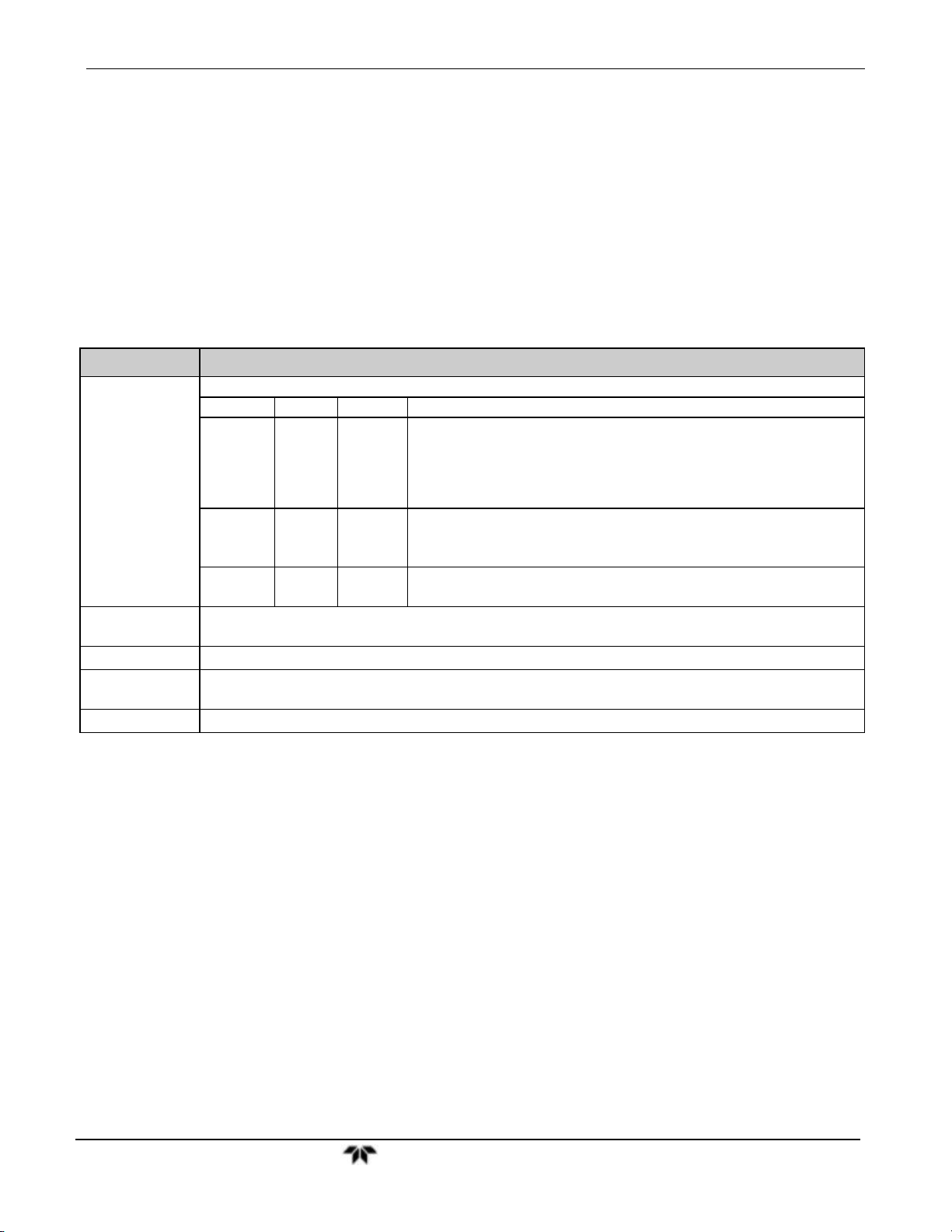
Model 9110TH NOx Analyzer Getting Started
The front panel liquid crystal display screen includes touch control. Upon analyzer startup, the screen shows a splash screen and other initialization indicators before the main
display appears, similar to Figure 3-2 above (may or may not display a Fault alarm). The
LEDs on the display screen indicate the Sample, Calibration and Fault states; also on the
screen is the gas concentration field (Conc), which displays real-time readouts for the
primary gas and for the secondary gas if installed. The display screen also shows what
mode the analyzer is currently in, as well as messages and data (Param). Along the
bottom of the screen is a row of touch control buttons; only those that are currently
applicable will have a label. Table 3-1 provides detailed information for each component
of the screen.
Table 3-1: Display Screen and Touch Control Description
Field Description/Function
Status LEDs indicating the states of Sample, Calibration and Fault, as follows:
Name Color State Definition
Off
On
SAMPLE Green
CAL Yellow
FAULT Red
Conc
Mode Displays the name of the analyzer’s current operating mode
Param
Control Buttons Displays dynamic, context sensitive labels on each button, which is blank when inactive until applicable.
Displays the actual concentration of the sample gas currently being measured by the analyzer in the
currently selected units of measure
Displays a variety of informational messages such as warning messages, operational data, test function
values and response messages during interactive tasks.
Blinking
Off
On
Blinking
Off
Blinking
Unit is not operating in sample mode, DAS is disabled.
Sample Mode active; Front Panel Display being updated; DAS data
being stored.
Unit is operating in sample mode, front panel display being updated,
DAS hold-off mode is ON, DAS disabled
Auto Cal disabled
Auto Cal enabled
Unit is in calibration mode
No warnings exist
Warnings exist
Figure 3-3 shows how the front panel display is mapped to the menu charts illustrated in
this manual. The Mode, Param (parameters), and Conc (gas concentration) fields in the
display screen are represented across the top row of each menu chart. The eight touch
control buttons along the bottom of the display screen are represented in the bottom row
of each menu chart.
Teledyne Analytical Instruments 10
 Loading...