

Page 1
INSTRUCTION MANUAL
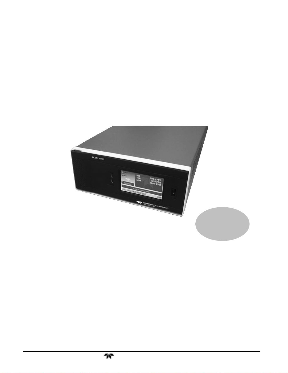
Model 9110T
Nitrogen Oxides Analyzer
P/N M9110T
DATE 11/15/13
TELEDYNE ELECTRONIC TECHNOLOGIES
Analytical Instruments
16830 Chestnut Street
City of Industry, CA 91748
Telephone: (626) 934-1500
Fax: (626) 961-2538
Web: www.teledyne-ai.com
Teledyne Analytical Instruments ii
Page 2

Model 9110T NOx Analyzer
Copyright © 2013 Teledyne Analytical Instruments
All Rights Reserved. No part of this manual may be reproduced, transmitted, transcribed, stored in a retrieval
system, or translated into any other language or computer language in whole or in part, in any form or by any
means, whether it be electronic, mechanical, magnetic, optical, manual, or otherwise, without the prior written
consent of Teledyne Analytical Instruments, 16830 Chestnut Street, City of Industry, CA 91748.
Warranty
This equipment is sold subject to the mutual agreement that it is warranted by us free from defects of material
and of construction, and that our liability shall be limited to replacing or repairing at our factory (without
charge, except for transportation), or at customer plant at our option, any material or construction in which
defects become apparent within one year from the date of shipment, except in cases where quotations or
acknowledgements provide for a shorter period. Components manufactured by others bear the warranty of their
manufacturer. This warranty does not cover defects caused by wear, accident, misuse, neglect or repairs other
than those performed by Teledyne or an authorized service center. We assume no liability for direct or indirect
damages of any kind and the purchaser by the acceptance of the equipment will assume all liability for any
damage which may result from its use or misuse.
We reserve the right to employ any suitable material in the manufacture of our apparatus, and to make any
alterations in the dimensions, shape or weight of any parts, in so far as such alterations do not adversely affect
our warranty.
Important Notice
This instrument provides measurement readings to its user, and serves as a tool by which valuable data can be
gathered. The information provided by the instrument may assist the user in eliminating potential hazards caused
by his process; however, it is essential that all personnel involved in the use of the instrument or its interface be
properly trained in the process being measured, as well as all instrumentation related to it.
The safety of personnel is ultimately the responsibility of those who control process conditions. While this
instrument may be able to provide early warning of imminent danger, it has no control over process conditions,
and it can be misused. In particular, any alarm or control systems installed must be tested and understood, both
as to how they operate and as to how they can be defeated. Any safeguards required such as locks, labels, or
redundancy, must be provided by the user or specifically requested of Teledyne at the time the order is placed.
Therefore, the purchaser must be aware of the hazardous process conditions. The purchaser is responsible for
the training of personnel, for providing hazard warning methods and instrumentation per the appropriate
standards, and for ensuring that hazard warning devices and instrumentation are maintained and operated
properly.
Teledyne Analytical Instruments, the manufacturer of this instrument, cannot accept responsibility for
conditions beyond its knowledge and control. No statement expressed or implied by this document or any
information disseminated by the manufacturer or its agents, is to be construed as a warranty of adequate safety
control under the user’s process conditions.
Trademarks
All trademarks, registered trademarks, brand names or product names appearing in this document are the
property of their respective owners and are used herein for identification purposes only.
Teledyne Analytical Instruments ii
Page 3

Model 9110TH NOx Analyzer Specific Configuration
INFORMATION ABOUT THE SPECIFIC CONFIGURATION OF YOUR
MODEL 9110T NOX ANALYZER
Note: All instruments must include the standard hardcopy manual.
SELECTED VERSIONS OF THE MODEL 9110T
Model 9110T— Standard Touch Screen Version
This Model 9110E NOx Analyzer is a touch screen version designed for analyzing the NOx
concentration in a background gas specified by the customer. It has a minimum settable range of 0-50
ppb and a maximum settable range of 0-10 ppm. The standard version is designed for ambient pressure
applications. The analyzer may have one or two analysis ranges with or without auto-ranging as listed
below. It includes an internal Moly converter and an external pump. Alarm relays are optional and if
included, that option will be checked below.
Model 9110TH — High Range Touch Screen Version
The Model 9110EH NOx Analyzer is a touch screen version designed for analyzing higher NOx
concentration (from 0-5 ppm to 0-5000 ppm) than the standard model. It includes an internal Hicon
converter and an external pump. Alarm relays are optional and if included, that option will be checked
below. There is no internal zero/span gas/oven option available for this model. The analyzer may have
one or two analysis ranges with or without autoranging as listed below.
This version is available with internal or external Hicon or Moly converters.
Model 9110TM — Mid-Range Touch Screen Version
The Model 9110EA NOx Analyzer is a touch screen version designed for analyzing a mid-range NOx
concentration. It has a minimum settable range of 0-1 ppm and a maximum settable range of 0-200 ppm.
t includes an internal Moly converter and an external pump. Alarm relays are optional and if included,
that option will be checked below. There is no internal zero/span gas/oven option available for this
model. The analyzer may have one or two analysis ranges with or without autoranging as listed below.
This model is similar to the EH version but does not have a sample bypass line. An optional
paramagnetic oxygen sensor is available for oxygen analysis in this version.
Converter Options
The 9110 is equipped with an internal Hicon thermal converter as standard equipment. Other
converters are available for the EH version as follows:
Internal Hicon (standard) External Hicon (2
Internal Moly External Moly (2
nd
set of rack mounts req’d)
nd
set of rack mounts req’d)
Teledyne Analytical Instruments iii
Page 4

Model 9110T NOx Analyzer Specific Configuration
Power Requirements
This Model 9110E is configured to operate from the following AC Power source:
100-120 VAC 60 Hz 220-240 VAC 60 Hz 100V 60 Hz
100-120 VAC 50 Hz 220-240 VAC 50 Hz 100V 50 Hz
Analog Output Signals
Analog output signals are available at A1, A2, and A3 on the rear panel. This instrument is configured
with the following analog outputs:
A1(NOx): 4-20 mA
A2 (NO): 0-5 V A2(NO): 4-20 mA
A3 (NO
): 0-5 V A2(NO2): 4-20 mA
2
Range Mode
The analyzer can be designed with a single or dual analysis ranges with auto-ranging or dual
independent ranges. This analyzer is configured with the following range mode:
Single Range:
Dual Range/Auto-ranging:
Low Range: Low Range:
High Range: High Range:
Dual Range/Independent:
Gas:
Selected Options for the Model 9110T
Mounting Options
19” rack mounting with 26” sliders with ears
19” rack mounting with ears only
Pump Mounting Options
None
Rack mounting hardware
Rear Panel Gas Fittings
1/4” SS Standard
6 mm SS Optional
Teledyne Analytical Instruments iv
Page 5

Model 9110TH NOx Analyzer Specific Configuration
Valve Options
No Valves
Internal SS Zero/Span Valves
Second Range Span Valve
Internal Zero/Span Valves with Oven (Not available for 9110EH/EM)
Internal Zero/Span Valves with Oven and Permeation Tube (Not available for 9110EH)
The permeation tube option installed depends on the sample gas and the effusion rate.
The specific permeation tube in this instrument is listed below:
Permeation tube Installed:
Alarm Relay Option
This option includes two concentration alarm relays.
Oxygen Sensor
This analyzer is equipped with a paramagnetic oxygen sensor for measuring the oxygen concentration
over the range of 0-25%
Gas Conditioner
A gas conditioner/dryer permeation gas exchange tube is installed for removing H2O and ammonia
from the sample stream. This item is required for EN certificatation.
Oxygenator
For applications where background gas less than 2% oxygen and using a Moly converter.
Remote Operation for Purged Enclosure
The operator interface is duplicated with switches mounted on the front door of the enclosure allowing
operation without compromising purge integrity.
Background Gas:
Notes:
Teledyne Analytical Instruments v
Page 6

Model 9110T NOx Analyzer Specific Configuration
This page intentionally left blank..
Teledyne Analytical Instruments vi
Page 7
Model 9110TH NOx Analyzer Safety Messages
SAFETY MESSAGES
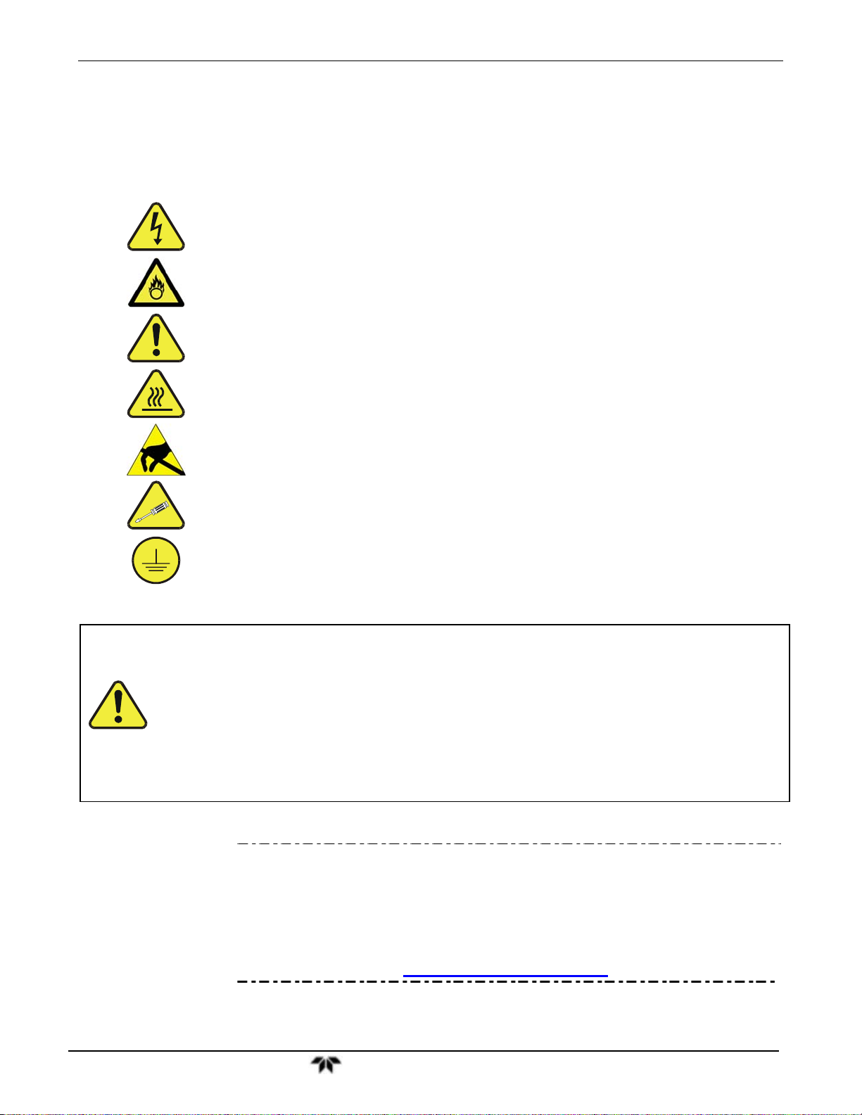
Important safety messages are provided throughout this manual for the purpose of avoiding personal
injury or instrument damage. Please read these messages carefully. Each safety message is associated
with a safety alert symbol, and are placed throughout this manual and inside the instrument. The symbols
with messages are defined as follows:
WARNING: Electrical Shock Hazard
HAZARD: Strong oxidizer
GENERAL WARNING/CAUTION: Read the accompanying message for
specific information.
CAUTION: Hot Surface Warning
Do Not Touch: Touching some parts of the instrument without protection or
proper tools could result in damage to the part(s) and/or the instrument.
Technician Symbol: All operations marked with this symbol are to be
performed by qualified maintenance personnel only.
Electrical Ground: This symbol inside the instrument marks the central
safety grounding point for the instrument.
Note
CAUTION
GENERAL SAFETY HAZARD
The T100 Analyzer should only be used for the purpose and in the
manner described in this manual. If you use the T100 in a manner other
than that for which it was intended, unpredictable behavior could ensue
with possible hazardous consequences.
NEVER use any gas analyzer to sample combustible gas(es).
Technical Assistance regarding the use and maintenance of the 9110T or
any other Teledyne product can be obtained by contacting Teledyne’s
Customer Service Department:
Phone: 626-934-1500
Email: ask_tai@teledyne.com
or by accessing various service options on our website at
http://www.teledyne-ai.com/.
Teledyne Analytical Instruments vii
Page 8

Model 9110T NOx Analyzer Safety Messages
CONSIGNES DE SÉCURITÉ
Des consignes de sécurité importantes sont fournies tout au long du présent manuel dans le but d’éviter des
blessures corporelles ou d’endommager les instruments. Veuillez lire attentivement ces consignes. Chaque
consigne de sécurité est représentée par un pictogramme d’alerte de sécurité; ces pictogrammes se retrouvent
dans ce manuel et à l’intérieur des instruments. Les symboles correspondent aux consignes suivantes :
AVERTISSEMENT : Risque de choc électrique
DANGER : Oxydant puissant
AVERTISSEMENT GÉNÉRAL / MISE EN GARDE : Lire la consigne
complémentaire pour des renseignements spécifiques
MISE EN GARDE : Surface chaude
Ne pas toucher : Toucher à certaines parties de l’instrument sans protection ou
sans les outils appropriés pourrait entraîner des dommages aux pièces ou à
l’instrument.
Pictogramme « technicien » : Toutes les opérations portant ce symbole doivent
être effectuées uniquement par du personnel de maintenance qualifié.
Mise à la terre : Ce symbole à l’intérieur de l’instrument détermine le point central
de la mise à la terre sécuritaire de l’instrument.
MISE EN GARDE
Cet instrument doit être utilisé aux fins décrites et de la manière décrite dans
ce manuel. Si vous utilisez cet instrument d’une autre manière que celle pour
laquelle il a été prévu, l’instrument pourrait se comporter de façon imprévisible
et entraîner des conséquences dangereuses.
NE JAMAIS utiliser un analyseur de gaz pour échantillonner des gaz
combustibles!
Teledyne Analytical Instruments viii
Page 9

Model 9110TH NOx Analyzer Safety Messages
ABOUT THIS MANUAL
This manual describes operation, specifications, and maintenance for the Model 9110T.
In addition this manual contains important SAFETY messages for this instrument. It is strongly
recommended that you read that operation manual in its entirety before operating the instrument.
ORGANIZATION
This manual is divided among three main parts and a collection of appendices at the end.
Part I contains introductory information that includes an overview of the analyzer, specifications,
descriptions of the available options, installation and connection instructions, and the initial calibration
and functional checks.
Part II comprises the operating instructions, which include initial functional checks and calibration,
basic, advanced and remote operation, advanced calibration, diagnostics, testing, and ends with specifics
of calibrating for use in EPA monitoring.
Part III provides detailed technical information, starting with maintenance, troubleshooting and service
with Frequently Asked Questions (FAQs), followed by principles of operation, and a glossary. It also
contains a special section dedicated to providing information about electro-static discharge and
protecting against its consequences.
The appendices at the end of this manual provide support information such as, version-specific software
documentation, lists of spare parts and recommended stocking levels, and schematics.
CONVENTIONS USED
In addition to the safety symbols as presented in the Important Safety Information page, this manual
provides special notices related to the safety and effective use of the analyzer and other pertinent
information.
Special Notices appear as follows:
ATTENTION
IMPORTANT
COULD DAMAGE INSTRUMENT AND VOID WARRANTY
This special notice provides information to avoid damage to your
instrument and possibly invalidate the warranty.
IMPACT ON READINGS OR DATA
Could either affect accuracy of instrument readings or cause loss of data.
Note Pertinent information associated with the proper care, operation or
maintenance of the analyzer or its parts.
Teledyne Analytical Instruments ix
Page 10

Model 9110T NOx Analyzer Safety Messages
This page intentionally left blank..
Teledyne Analytical Instruments x
Page 11

Model 9110TH NOx Analyzer Table of Contents
TABLE OF CONTENTS
Information About the Specific Configuration of Your Model 9110T NOX Analyzer ..............................................................iii
Mounting Options .............................................................................................................................................................. iv
Pump Mounting Options .................................................................................................................................................... iv
Rear Panel Gas Fittings.................................................................................................................................................... iv
Safety Messages ....................................................................................................................................................................vii
About This Manual ................................................................................................................................................................. ix
PART I GENERAL INFORMATION .................................................................................................................................... 21
1. Introduction, Features and Options ........................................................................................................................................ 23
1.1. Overview ........................................................................................................................................................................ 23
1.2. Features ......................................................................................................................................................................... 23
1.3. Documentation ............................................................................................................................................................... 24
1.4. Options ........................................................................................................................................................................... 24
2. Specifications, Approvals, & Compliance ............................................................................................................................... 27
2.1. Specifications ................................................................................................................................................................. 27
2.2. EPA Equivalency Designation ........................................................................................................................................ 28
2.3. Approvals and Certifications ........................................................................................................................................... 29
2.3.1. Safety ..................................................................................................................................................................... 29
2.3.2. EMC ........................................................................................................................................................................ 29
2.3.3. Other Type Certifications ........................................................................................................................................ 29
3. Getting Started 31
3.1. Unpacking the 9110T Analyzer ...................................................................................................................................... 31
3.1.1. Ventilation Clearance .............................................................................................................................................. 32
3.2. Instrument Layout ........................................................................................................................................................... 32
3.2.1. Front Panel ............................................................................................................................................................. 33
3.2.2. Rear Panel .............................................................................................................................................................. 37
3.2.3. Internal Chassis Layout .......................................................................................................................................... 38
3.3. Connections and Setup .................................................................................................................................................. 41
3.3.1. Electrical Connections ............................................................................................................................................ 41
3.3.2. Pneumatic Connections .......................................................................................................................................... 55
3.4. Startup, Functional Checks, and Initial Calibration ......................................................................................................... 74
3.4.1. Start Up .................................................................................................................................................................. 74
3.4.2. Warning Messages ................................................................................................................................................. 75
3.4.3. Functional Checks .................................................................................................................................................. 77
3.4.4. Initial Calibration ..................................................................................................................................................... 77
3.4.4.1. Interferents .......................................................................................................................................................... 78
PART II – OPERATING INSTRUCTIONS ............................................................................................................................ 85
4. Overview of Operating Modes ................................................................................................................................................ 87
4.1. Sample Mode ................................................................................................................................................................. 88
4.1.1. Test Functions ........................................................................................................................................................ 88
4.1.2. Warning Messages ................................................................................................................................................. 91
4.2. Calibration Mode ............................................................................................................................................................ 92
4.3. Setup Mode .................................................................................................................................................................... 92
4.3.1. Password Security .................................................................................................................................................. 93
4.3.2. Primary Setup Menu ............................................................................................................................................... 93
4.3.3. Secondary Setup Menu (SETUP MORE) ............................................................................................................ 93
5. Setup Menu 95
5.1. SETUP CFG: Configuration Information .................................................................................................................... 95
5.2. SETUP ACAL: Automatic Calibration Option .............................................................................................................. 95
5.3. SETUP DAS: Internal Data Acquisition System .......................................................................................................... 95
5.4. SETUP RNGE: Analog Output Reporting Range Configuration ................................................................................. 96
5.4.1. 9110T Physical Ranges .......................................................................................................................................... 96
5.4.2. 9110T Analog Output Reporting Ranges ................................................................................................................ 96
5.4.3. SETUP RNGE MODE .................................................................................................................................... 98
5.5. SETUP PASS: Password Protection ........................................................................................................................ 106
5.6. SETUP CLK: Setting the Internal Time-of-Day Clock .............................................................................................. 108
5.6.1. Setting the Time of Day ........................................................................................................................................ 108
5.6.2. Adjusting the Internal Clock’s Speed .................................................................................................................... 109
5.7. SETUP COMM: Communications Ports ................................................................................................................... 110
5.7.1. ID (Machine Identification) .................................................................................................................................... 110
5.7.2. INET (Ethernet) .................................................................................................................................................... 111
5.7.3. COM1[COM2] (Mode, Baude Rate and Test Port) ............................................................................................... 111
5.8. SETUP VARS: Variables Setup and Definition ........................................................................................................ 111
Teledyne Analytical Instruments 11
Page 12

Model 9110T NOx Analyzer Table of Contents
5.9. SETUP Diag: Diagnostics Functions ........................................................................................................................ 114
5.9.1. Signal I/O .............................................................................................................................................................. 116
5.9.2. Analog Output (DIAG AOUT) ................................................................................................................................ 117
5.9.3. Analog I/O Configuration (DIAG AIO) ................................................................................................................... 117
5.9.4. Test Chan Output (Selecting a Test Channel Function for Output A4) ................................................................. 132
5.9.5. Optic Test ............................................................................................................................................................. 133
5.9.6. Electrical Test ....................................................................................................................................................... 134
5.9.7. Ozone Gen Override ............................................................................................................................................. 134
5.9.8. Flow Calibration .................................................................................................................................................... 134
6. Communications Setup and Operation ................................................................................................................................ 135
6.1. Data Terminal / Communication Equipment (DTE DEC) .............................................................................................. 135
6.2. Communication Modes, Baud Rate and Port Testing ................................................................................................... 135
6.2.1. Communication Modes ......................................................................................................................................... 135
6.2.2. Com Port Baud Rate ............................................................................................................................................. 138
6.2.3. Com Port Testing .................................................................................................................................................. 138
6.3. RS-232 ......................................................................................................................................................................... 139
6.4. RS-485 (Option) ........................................................................................................................................................... 140
6.5. Ethernet ........................................................................................................................................................................ 140
6.5.1. Configuring Ethernet Communication Manually (Static IP Address) ..................................................................... 140
6.5.2. Configuring Ethernet Communication Using Dynamic Host Configuration Protocol (DHCP) ................................ 143
6.6. USB Port for Remote Access ....................................................................................................................................... 147
6.7. Communications Protocols ........................................................................................................................................... 149
6.7.1. MODBUS .............................................................................................................................................................. 149
6.7.2. Hessen ................................................................................................................................................................. 151
7. Data Acquisition System (DAS) and APICOM ..................................................................................................................... 163
7.1. DAS Structure .............................................................................................................................................................. 164
7.1.1. DAS Channels ...................................................................................................................................................... 164
7.1.2. Viewing DAS Data and Settings ........................................................................................................................... 168
7.1.3. Editing DAS Data Channels .................................................................................................................................. 169
7.2. Remote DAS Configuration .......................................................................................................................................... 181
7.2.1. DAS Configuration via APICOM ........................................................................................................................... 181
7.2.2. DAS Configuration via Terminal Emulation Programs .......................................................................................... 183
8. Remote Operation 185
8.1. Computer Mode ............................................................................................................................................................ 185
8.1.1. Remote Control via APICOM ................................................................................................................................ 185
8.2. Interactive Mode ........................................................................................................................................................... 185
8.2.1. Remote Control via a Terminal Emulation Program.............................................................................................. 185
8.3. Remote Access by Modem ........................................................................................................................................... 188
8.4. Password Security for Serial Remote Communications ............................................................................................... 191
9. Calibration Procedures 193
9.1. Before Calibration ......................................................................................................................................................... 194
9.1.1. Required Equipment, Supplies, and Expendables ................................................................................................ 194
9.1.2. Calibration Gases ................................................................................................................................................. 195
9.1.3. Data Recording Devices ....................................................................................................................................... 196
9.1.4. NO2 Conversion Efficiency (CE) ........................................................................................................................... 197
9.2. Manual Calibration Checks and Calibration of the 9110T Analyzer in its Base Configuration ...................................... 197
9.2.1. Setup for Basic Calibration Checks and Calibration of the 9110T analyzer. ......................................................... 197
9.2.2. Performing a Basic Manual Calibration Check ..................................................................................................... 199
9.2.3. Performing a Basic Manual Calibration ................................................................................................................. 199
9.3. Manual Calibration with the Internal Span Gas Generator ........................................................................................... 202
9.3.1. Performing “Precision” Manual Calibration when Internal Span Gas (IZS) Generator Option is Present ............. 202
9.3.2. Setup for Calibration with the Internal Span Gas Generator ................................................................................. 203
9.3.3. CAL On NO2 Feature ............................................................................................................................................ 203
9.3.4. Performing a Manual Calibration Check with the Internal Span Gas Generator ................................................... 205
9.3.5. Performing a Manual Calibration with the Internal Span Gas Generator .............................................................. 206
9.4. Manual Calibration and Cal Checks with the Valve Options Installed .......................................................................... 209
9.4.1. Setup for Calibration Using Valve Options ............................................................................................................ 209
9.4.2. Manual Calibration Checks with Valve Options Installed ...................................................................................... 210
9.4.3. Manual Calibration Using Valve Options .............................................................................................................. 211
9.5. Automatic Zero/Span Cal/Check (AutoCal) .................................................................................................................. 213
9.5.1. SETUP ACAL: Programming and AUTO CAL Sequence ................................................................................ 216
9.6. Calibration Quality Analysis .......................................................................................................................................... 219
9.7. Gas Flow Calibration .................................................................................................................................................... 220
10. EPA Protocol Calibration .................................................................................................................................................... 221
10.1. 9110T Calibration – General Guidelines .................................................................................................................... 221
Teledyne Analytical Instruments 12
Page 13

Model 9110TH NOx Analyzer Table of Contents
10.2. Calibration Equipment, Supplies, and Expendables ................................................................................................... 222
10.2.1. Spare Parts and Expendable Supplies ............................................................................................................... 222
10.2.2. Calibration Gas and Zero Air Sources ................................................................................................................ 223
10.2.3. Data Recording Device ....................................................................................................................................... 223
10.2.4. Record Keeping .................................................................................................................................................. 223
10.3. Calibration Frequency ................................................................................................................................................ 223
10.4. Level 1 Calibrations versus Level 2 Checks ............................................................................................................... 224
10.5. Gas Phase Titration (GPT) ......................................................................................................................................... 225
10.5.1. GPT Principle of Operation ................................................................................................................................. 225
10.5.2. GPT Calibrator Check Procedure ....................................................................................................................... 225
10.6. GPT Multipoint Calibration Procedure ........................................................................................................................ 228
10.6.1. Set Up for GPT Multipoint Calibration of the 9110T ............................................................................................ 229
10.6.2. Zero Calibration .................................................................................................................................................. 230
10.6.3. Span Calibration ................................................................................................................................................. 230
10.7. GPT NO2 Check ......................................................................................................................................................... 231
10.8. Other Quality Assurance Procedures ......................................................................................................................... 232
10.8.1. Summary of Quality Assurance Checks ............................................................................................................. 232
10.8.2. Short Calibration Checks .................................................................................................................................... 233
10.8.3. Zero/Span Check Procedures ............................................................................................................................ 233
10.8.4. Precision Check .................................................................................................................................................. 234
10.9. Certification of Working Standards ............................................................................................................................. 234
10.10. References ............................................................................................................................................................... 235
PART III – Maintenance and Service .................................................................................................................................. 237
11. Instrument Maintenance ..................................................................................................................................................... 239
11.1. Maintenance Schedule ............................................................................................................................................... 239
11.2. Predictive Diagnostics ................................................................................................................................................ 241
11.3. Maintenance Procedures ............................................................................................................................................ 241
11.3.1. Replacing the Sample Particulate Filter .............................................................................................................. 242
11.3.2. Changing the O3 Dryer Particulate Filter ............................................................................................................. 243
11.3.3. Changing the Ozone Cleanser Chemical ............................................................................................................ 244
11.3.4. Maintaining the External Sample Pump (Pump Pack) ........................................................................................ 247
11.3.5. Changing the Pump DFU Filter ........................................................................................................................... 247
11.3.6. Changing the Internal Span Gas Generator Permeation Tube ........................................................................... 249
11.3.7. Changing the External Zero Air Scrubber (OPT 86C) ......................................................................................... 249
11.3.8. Changing the NO2 Converter .............................................................................................................................. 252
11.3.9. Cleaning the Reaction Cell ................................................................................................................................. 254
11.3.10. Replacing Critical Flow Orifices ........................................................................................................................ 256
11.3.11. Checking for Light Leaks .................................................................................................................................. 257
11.3.12. Checking for Pneumatic Leaks ......................................................................................................................... 258
12. Troubleshooting & Service ................................................................................................................................................. 261
12.1. General Troubleshooting ............................................................................................................................................ 261
12.1.1. Fault Diagnosis with WARNING Messages ........................................................................................................ 262
12.1.2. Fault Diagnosis With Test Functions .................................................................................................................. 266
12.1.3. DIAG SIGNAL I/O: Using the Diagnostic Signal I/O Function ....................................................................... 267
12.2. Using the Analog Output Test Channel ...................................................................................................................... 269
12.3. Using the Internal Electronic Status LEDs .................................................................................................................. 270
12.3.1. CPU Status Indicator .......................................................................................................................................... 270
12.3.2. Relay PCA Status LEDs ..................................................................................................................................... 270
12.4. Gas Flow Problems .................................................................................................................................................... 272
12.4.1. Zero or Low Flow Problems ................................................................................................................................ 272
12.5. Calibration Problems .................................................................................................................................................. 276
12.5.1. Negative Concentrations .................................................................................................................................... 276
12.5.2. No Response ...................................................................................................................................................... 277
12.5.3. Unstable Zero and Span ..................................................................................................................................... 277
12.5.4. Inability to Span - No SPAN Button (CALS) ........................................................................................................ 278
12.5.5. Inability to Zero - No ZERO Button (CALZ) ......................................................................................................... 278
12.5.6. Non-Linear Response ......................................................................................................................................... 279
12.5.7. Discrepancy Between Analog Output and Display ............................................................................................. 280
12.5.8. Discrepancy Between NO and NOX slopes ........................................................................................................ 280
12.6. Other Performance Problems ..................................................................................................................................... 281
12.6.1. Excessive Noise ................................................................................................................................................. 281
12.6.2. Slow Response ................................................................................................................................................... 281
12.6.3. Auto Zero Warnings ........................................................................................................................................... 282
12.7. Subsystem Checkout.................................................................................................................................................. 283
12.7.1. AC Main Power ................................................................................................................................................... 283
Teledyne Analytical Instruments 13
Page 14

Model 9110T NOx Analyzer Table of Contents
12.7.2. DC Power Supply ............................................................................................................................................... 283
12.7.3. I2C Bus ............................................................................................................................................................... 285
12.7.4. LCD/Display Module ........................................................................................................................................... 285
12.7.5. Relay PCA .......................................................................................................................................................... 285
12.7.6. Motherboard ....................................................................................................................................................... 285
12.7.7. Pressure / Flow Sensor Assembly ...................................................................................................................... 289
12.7.8. CPU .................................................................................................................................................................... 290
12.7.9. RS-232 Communications .................................................................................................................................... 290
12.7.10. NO2 NO Converter ....................................................................................................................................... 291
12.7.11. Simplified GPT Calibration ................................................................................................................................ 296
12.7.12. Photomultiplier Tube (PMT) Sensor Module ..................................................................................................... 300
12.7.13. PMT Preamplifier Board ................................................................................................................................... 302
12.7.14. PMT Temperature Control PCA ........................................................................................................................ 303
12.7.15. O3 Generator .................................................................................................................................................... 304
12.7.16. Internal Span Gas Generator and Valve Options ............................................................................................. 305
12.7.17. Temperature Sensor ......................................................................................................................................... 306
12.8. Service Procedures .................................................................................................................................................... 308
12.8.1. Disk-On-Module Replacement Procedure .......................................................................................................... 308
12.8.2. O3 Generator Replacement ................................................................................................................................ 309
12.8.3. Sample and Ozone (Perma Pure®) Dryer Replacement ..................................................................................... 309
12.8.4. PMT Sensor Hardware Calibration ..................................................................................................................... 310
12.8.5. Replacing the PMT, HVPS or TEC ..................................................................................................................... 312
12.8.6. Removing / Replacing the Relay PCA from the Instrument ................................................................................ 315
12.9. Frequently Asked Questions ...................................................................................................................................... 316
12.10. Technical Assistance ................................................................................................................................................ 318
13. Principles of Operation ....................................................................................................................................................... 319
13.1. Measurement Principle ............................................................................................................................................... 319
13.1.1. Chemiluminescence Creation in the 9110T Reaction Cell .................................................................................. 319
13.1.2. Chemiluminescence Detection in the 9110T Reaction Cell ................................................................................ 320
13.1.3. NOX and NO2 Determination ............................................................................................................................... 321
13.1.4. Auto Zero ............................................................................................................................................................ 322
13.1.5. Measurement Interferences ................................................................................................................................ 323
13.2. Pneumatic Operation .................................................................................................................................................. 326
13.2.1. Sample Gas Flow ............................................................................................................................................... 326
13.2.2. Flow Rate Control - Critical Flow Orifices ........................................................................................................... 330
13.2.3. Ozone Gas Generation and Air Flow .................................................................................................................. 332
13.2.4. Pneumatic Sensors ............................................................................................................................................. 335
13.3. Electronic Operation ................................................................................................................................................... 338
13.3.1. Overview ............................................................................................................................................................. 338
13.3.2. CPU .................................................................................................................................................................... 339
13.3.3. Motherboard ....................................................................................................................................................... 340
13.3.4. Relay PCA .......................................................................................................................................................... 345
13.4. Sensor Module, Reaction Cell .................................................................................................................................... 351
13.5. Photo Multiplier Tube (PMT) ....................................................................................................................................... 352
13.5.1. PMT Preamplifier ................................................................................................................................................ 353
13.5.2. PMT Cooling System .......................................................................................................................................... 355
13.6. Pneumatic Sensor Board ............................................................................................................................................ 356
13.7. Power Supply/Circuit Breaker ..................................................................................................................................... 357
13.7.1. AC Power Configuration ..................................................................................................................................... 358
13.8. Front Panel Touchscreen/Display Interface ................................................................................................................ 363
13.8.1. LVDS Transmitter Board ..................................................................................................................................... 364
13.8.2. Front Panel Touchscreen/Display Interface PCA ............................................................................................... 364
13.9. Software Operation .................................................................................................................................................... 364
13.9.1. Adaptive Filter ..................................................................................................................................................... 365
13.9.2. Temperature/Pressure Compensation (TPC) ..................................................................................................... 365
13.9.3. Calibration - Slope and Offset ............................................................................................................................. 365
14. A Primer on Electro-Static Discharge ................................................................................................................................. 367
14.1. How Static Charges are Created ................................................................................................................................ 367
14.2. How Electro-Static Charges Cause Damage .............................................................................................................. 368
14.3. Common Myths About ESD Damage ......................................................................................................................... 369
14.4. Basic Principles of Static Control ................................................................................................................................ 369
14.4.1. General Rules ..................................................................................................................................................... 369
14.5. Basic anti-ESD Procedures for Analyzer Repair and Maintenance ............................................................................ 371
14.5.1. Working at the Instrument Rack ......................................................................................................................... 371
14.5.2. Working at an Anti-ESD Work Bench ................................................................................................................. 371
Teledyne Analytical Instruments 14
Page 15

Model 9110TH NOx Analyzer Table of Contents
14.5.3. Transferring Components Between Rack and Bench ......................................................................................... 372
14.5.4. Opening Shipments from TAI Customer Service ................................................................................................ 372
14.5.5. Packing Components for Return to TAI Customer Service ................................................................................. 373
Glossary .............................................................................................................................................................................. 375
APPENDIX A - VERSION SPECIFIC SOFTWARE DOCUMENTATION
APPENDIX B - SPARE PARTS
APPENDIX C - REPAIR QUESTIONNAIRE
APPENDIX D - ELECTRONIC SCHEMATICS
Teledyne Analytical Instruments 15
Page 16

Model 9110T NOx Analyzer Table of Contents
FIGURES
Figure 3-1: Front Panel Layout....................................................................................................................... 33
Figure 3-2: Display Screen and Touch Control .............................................................................................. 34
Figure 3-3: Display/Touch Control Screen Mapped to Menu Charts ............................................................. 36
Figure 3-4: Rear Panel Layout – Base Unit ................................................................................................... 37
Figure 3-5: Internal Layout – Top View with IZS Option ................................................................................ 39
Figure 3-6: Internal Layout - Top View Showing Other Options .................................................................... 40
Figure 3-7: Analog In Connector .................................................................................................................... 42
Figure 3-8: Analog Output Connector ............................................................................................................ 43
Figure 3-9: Current Loop Option Installed on the Motherboard ..................................................................... 44
Figure 3-10: Status Output Connector ............................................................................................................. 45
Figure 3-11: Energizing the 9110T Control Inputs ........................................................................................... 46
Figure 3-12: Concentration Alarm Relay .......................................................................................................... 47
Figure 3-13 Rear Panel Connector Pin-Outs for RS-232 Mode ...................................................................... 50
Figure 3-14: Default Pin Assignments for CPU COMM Port Connector (RS-232). ......................................... 51
Figure 3-15: Jumper and Cables for Multidrop Mode....................................................................................... 53
Figure 3-16: RS-232-Multidrop PCA Host/Analyzer Interconnect Diagram ..................................................... 54
Figure 3-17: Gas Line Connections from Calibrator – Basic 9110T Configuration .......................................... 59
Figure 3-18: Gas Line Connections from Bottled Span Gas – Basic 9110T Configuration ............................. 60
Figure 3-19: Pneumatics, Basic Configuration ................................................................................................. 62
Figure 3-20: Rear Panel Layout with Z/S Valve Options (OPT 50A) ............................................................... 63
Figure 3-21: Gas Line Connections for 9110T with Z/S Valves Option (OPT 50A) ......................................... 63
Figure 3-22: Pneumatics with Zero/Span Valves OPT 50A ............................................................................. 65
Figure 3-23: Rear Panel Layout with Ambient Zero/Pressurized Span Valves OPT 50B ................................ 66
Figure 3-24: Gas Line Connection w/Ambient Zero/Pressurized Span Valves (OPT 50B) ............................. 67
Figure 3-25: Pneumatics with Ambient Zero/Pressurized Span Valves (OPT 50B) ........................................ 68
Figure 3-26: Rear Panel Layout with Internal Span Source (IZS) OPT 50G ................................................... 70
Figure 3-27: Pneumatics with the Internal Span Gas Generator (OPT 50G) .................................................. 71
Figure 3-28: Pneumatics for Sample Conditioner OPT 86A ............................................................................ 72
Figure 3-29: Pneumatics for External Zero Air Scrubber (OPT 86C) for Z/S Valves ....................................... 73
Figure 4-1: Front Panel Display ...................................................................................................................... 87
Figure 4-2: Viewing 9110T Test Functions .................................................................................................... 90
Figure 5-1: Analog Output Connector Pin Out ............................................................................................... 97
Figure 5-2. SETUP – COMM Menu .............................................................................................................110
Figure 5-3. COMM– Machine ID ..................................................................................................................111
Figure 5-4: Accessing the DIAG Submenus ................................................................................................115
Figure 5-5: Accessing the Analog I/O Configuration Submenus ..................................................................118
Figure 5-6: Setup for Checking / Calibrating DCV Analog Output Signal Levels .........................................123
Figure 5-7: Setup for Checking / Calibration Current Output Signal Levels Using an Ammeter .................125
Figure 5-8: Alternative Setup Using 250Ω Resistor for Checking Current Output Signal Levels ................127
Figure 6-1. COMM – Communication Modes Setup ....................................................................................137
Figure 6-2. COMM – COMM Port Baud Rate ..............................................................................................138
Figure 6-3. COMM – COM1 Test Port .........................................................................................................139
Figure 6-4. COMM - LAN /Internet Manual Configuration ............................................................................142
Figure 6-5. COMM – LAN / Internet Automatic Configuration (DHCP) ........................................................145
Figure 6-6. COMM – Change Hostname ....................................................................................................146
Figure 7-1: Default DAS Channels Setup ....................................................................................................167
Figure 7-2: APICOM Remote Control Program Interface ............................................................................181
Figure 7-3: Sample APICOM User Interface for Configuring the DAS .........................................................182
Figure 7-4: DAS Configuration Through a Terminal Emulation Program ....................................................183
Figure 8-1: Remote Access by Modem ........................................................................................................189
Figure 9-1: Set up for Manual Calibrations/Checks of 9110T’s in Base Configuration w/ a Gas Dilution
Calibrator ...................................................................................................................................198
Figure 9-2: Set up for Manual Calibrations/Checks of 9110T’s in Base Configuration w/ Bottled Gas .......198
Figure 9-3: Pneumatic Connections for 9110T Precision Calibration when IZS Generator Present ...........202
Figure 9-4: Pneumatic Connections for Manual Calibration/Checks with the Internal Span Gas Generator203
Teledyne Analytical Instruments 16
Page 17

Model 9110TH NOx Analyzer Table of Contents
Figure 10-1: GPT Calibration System ............................................................................................................229
Figure 11-1 Replacing the Particulate Filter ..................................................................................................242
Figure 11-2: Particle Filter on O3 Supply Air Dryer ........................................................................................243
Figure 11-3: Ozone Cleanser Assembly ........................................................................................................245
Figure 11-4: Zero Air Scrubber Assembly ......................................................................................................251
Figure 11-5: NO2 Converter Assembly ...........................................................................................................253
Figure 11-6: Reaction Cell Assembly .............................................................................................................255
Figure 11-7: Critical Flow Orifice Assembly ...................................................................................................256
Figure 12-1: Example of Signal I/O Function .................................................................................................268
Figure 12-2: CPU Status Indicator .................................................................................................................270
Figure 12-3: Relay PCA Status LEDS Used for Troubleshooting ..................................................................271
Figure 12-4: Location of DC Power Test Points on Relay PCA .....................................................................284
Figure 12-5: Typical Set Up of Status Output Test ........................................................................................287
Figure 12-6: Pressure / Flow Sensor Assembly .............................................................................................289
Figure 12-7: Setup for determining NO2 NO Efficiency – 9110T Base Configuration ...............................293
Figure 12-8: Pre-Amplifier Board Layout ........................................................................................................311
Figure 12-9: 9110T Sensor Assembly ............................................................................................................313
Figure 12-10: Relay PCA with AC Relay Retainer In Place .............................................................................315
Figure 12-11: Relay PCA Mounting Screw Locations .....................................................................................316
Figure 13-1: Reaction Cell with PMT Tube and Optical Filter ........................................................................321
Figure 13-2: 9110T Sensitivity Spectrum .......................................................................................................321
Figure 13-3: NO2 NO Conversion ...............................................................................................................322
Figure 13-4: Pneumatic Flow During the Auto Zero Cycle .............................................................................323
Figure 13-5: Internal Gas Flow for Basic 9110T with External Pump ............................................................327
Figure 13-6: Basic Internal Gas Flow for Basic 9110T with Internal Pump ...................................................328
Figure 13-7. Vacuum Manifold, Standard Configuration ................................................................................329
Figure 13-8: Flow Control Assembly & Critical Flow Orifice ..........................................................................330
Figure 13-9: Location of Flow Control Assemblies & Critical Flow Orifices ...................................................331
Figure 13-10: Ozone Generator Principle ........................................................................................................333
Figure 13-11: Semi-Permeable Membrane Drying Process ............................................................................334
Figure 13-12: 9110T Perma Pure® Dryer .........................................................................................................334
Figure 13-13: 9110T Electronic Block Diagram ...............................................................................................338
Figure 13-14: CPU Board .................................................................................................................................340
Figure 13-15: Relay PCA Layout (P/N 045230100) .........................................................................................345
Figure 13-16: Relay PCA P/N 045230100 with AC Relay Retainer in Place ...................................................346
Figure 13-17: Status LED Locations – Relay PCA ...........................................................................................348
Figure 13-18: Heater Control Loop Block Diagram. .........................................................................................349
Figure 13-19: Thermocouple Configuration Jumper (JP5) Pin-Outs ................................................................351
Figure 13-20: 9110T Sensor Module Assembly ...............................................................................................352
Figure 13-21: Basic PMT Design .....................................................................................................................353
Figure 13-22: PMT Preamp Block Diagram .....................................................................................................354
Figure 13-23: Typical Thermo-Electric Cooler .................................................................................................355
Figure 13-24: PMT Cooling System Block Diagram .........................................................................................356
Figure 13-25: Power Distribution Block Diagram .............................................................................................358
Figure 13-26: Location of AC power Configuration Jumpers ...........................................................................359
Figure 13-27: Pump AC Power Jumpers (JP7) ................................................................................................360
Figure 13-28: Typical Set Up of AC Heater Jumper Set (JP2) ........................................................................361
Figure 13-29: Typical Jumper Set (JP2) Set Up of Heaters ............................................................................362
Figure 13-30: Front Panel and Display Interface Block Diagram .....................................................................363
Figure 13-31: Basic Software Operation ..........................................................................................................364
Figure 14-1: Triboelectric Charging ................................................................................................................367
Figure 14-2: Basic anti-ESD Workbench .......................................................................................................370
Teledyne Analytical Instruments 17
Page 18

Model 9110T NOx Analyzer Table of Contents
TABLES
Table 1-1. Analyzer Options .......................................................................................................................... 24
Table 2-2: Software Settings for EPA Equivalence....................................................................................... 28
Table 3-1: Ventilation Clearance ................................................................................................................... 32
Table 3-5: Analog Output Pin Assignments .................................................................................................. 43
Table 3-6: Status Output Pin Assignments ................................................................................................... 45
Table 3-7: Control Input Pin Assignments .................................................................................................... 46
Table 3-8: NIST-SRM's Available for Traceability of NOx Calibration Gases ................................................ 57
Table 3-9: Zero/Span Valves Operating States OPT 50A ............................................................................ 65
Table 3-10: Valve Operating States OPT 50B installed .................................................................................. 69
Table 3-11: Internal Span Gas Generator Valve Operating States OPT 50G ................................................ 71
Table 3-12: Possible Warning Messages at Start-Up ..................................................................................... 76
Table 4-1: Analyzer Operating Modes .......................................................................................................... 88
Table 4-2: Test Functions Defined ................................................................................................................ 88
Table 4-3: Warning Messages Defined ......................................................................................................... 91
Table 4-4: Primary Setup Mode Features and Functions ............................................................................. 93
Table 4-5: Secondary Setup Mode Features and Functions ........................................................................ 93
Table 5-1: IND Mode Analog Output Assignments ....................................................................................... 99
Table 5-2: Password Levels ........................................................................................................................106
Table 5-3: Variable Names (VARS) ............................................................................................................112
Table 5-4: Diagnostic Mode (DIAG) Functions ...........................................................................................114
Table 5-5: DIAG - Analog I/O Functions .....................................................................................................117
Table 5-6: Analog Output Voltage Range Min/Max ....................................................................................119
Table 5-7: Voltage Tolerances for the TEST CHANNEL Calibration ..........................................................123
Table 5-8: Current Loop Output Check .......................................................................................................127
Table 5-9: Test Channels Functions available on the 9110T’s Analog Output ...........................................132
Table 6-1: COMM Port Communication Modes ..........................................................................................135
Table 6-2: Ethernet Status Indicators .........................................................................................................140
Table 6-4: RS-232 Communication Parameters for Hessen Protocol ........................................................151
Table 6-5: Teledyne's Hessen Protocol Response Modes .........................................................................154
Table 6-6: Default Hessen Status Flag Assignments .................................................................................159
Table 7-1: Front Panel LED Status Indicators for DAS ...............................................................................163
Table 7-2: DAS Data Channel Properties ...................................................................................................164
Table 7-3: DAS Data Parameter Functions ................................................................................................172
Table 8-1: Terminal Mode Software Commands ........................................................................................186
Table 8-2: Teledyne API's Serial I/O Command Types ..............................................................................186
Table 9-1: IZS Option Valve States with CAL_ON_NO2 Turned ON ..........................................................203
Table 9-2: AUTOCAL Modes ......................................................................................................................213
Table 9-3: AutoCal Attribute Setup Parameters ..........................................................................................214
Table 9-4: Example AutoCal Sequence ......................................................................................................215
Table 9-5: Calibration Data Quality Evaluation ...........................................................................................219
Table 10-1: Activity Matrix for EPA Calibration Equipment and Supplies .....................................................222
Table 10-2: Definition of Level 1 and Level 2 Zero and Span Checks .........................................................224
Table 10-3: Activity Matrix for Data Quality ...................................................................................................233
Table 11-1: 9110T Maintenance Schedule ...................................................................................................240
Table 11-2: Predictive Uses for Test Functions ............................................................................................241
Table 12-1: Front Panel Warning Messages ................................................................................................264
Table 12-2: Test Functions - Indicated Failures ............................................................................................266
Table 12-3: Test Channel Outputs as Diagnostic Tools ...............................................................................269
Table 12-4: Relay PCA Watchdog LED Failure Indications ..........................................................................270
Table 12-5: Relay PCA Status LED Failure Indications ................................................................................271
Table 12-6: DC Power Test Point and Wiring Color Codes ..........................................................................284
Table 12-7: DC Power Supply Acceptable Levels ........................................................................................284
Table 12-8: Relay PCA Control Devices .......................................................................................................285
Table 12-9: Analog Output Test Function - Nominal Values Voltage Outputs .............................................286
Table 12-10: Status Outputs Check ................................................................................................................288
Table 12-11: 9110T Control Input Pin Assignments and Corresponding Signal I/O Functions ......................288
Teledyne Analytical Instruments 18
Page 19

Model 9110TH NOx Analyzer Table of Contents
Table 13-1: List of Interferents ......................................................................................................................325
Table 13-2: 9110T Valve Cycle Phases ........................................................................................................329
Table 13-3: 9110T Gas Flow Rates ..............................................................................................................331
Table 13-4: Relay PCA Status LED’s ...........................................................................................................347
Table 13-5: Thermocouple Configuration Jumper (JP5) Pin-Outs ................................................................350
Table 13-6: AC Power Configuration for Internal Pumps (JP7) ....................................................................360
Table 13-7: Power Configuration for Standard AC Heaters (JP2) ................................................................361
Table 13-8: Power Configuration for Optional Heaters (JP6) .......................................................................362
Table 14-1: Static Generation Voltages for Typical Activities .......................................................................367
Table 14-2: Sensitivity of Electronic Devices to Damage by ESD ................................................................368
Teledyne Analytical Instruments 19
Page 20

Model 9110T NOx Analyzer Table of Contents
This page intentionally left blank.
Teledyne Analytical Instruments 20
Page 21

Model 9110TH NOx Analyzer Part I
PART I
GENERAL INFORMATION
Teledyne Analytical Instruments 21
Page 22

Model 9110T NOx Analyzer Part I
This page intentionally left blank.
Teledyne Analytical Instruments 22
Page 23

Model 9110TH NOx Analyzer Introduction
1. INTRODUCTION, FEATURES AND OPTIONS
1.1. OVERVIEW
The Model 9110T Nitrogen Oxides Analyzer uses chemiluminescence detection, coupled with
state-of-the-art microprocessor technology to provide the sensitivity, stability and ease of use
needed for ambient or dilution CEM monitoring requirements of nitric oxide (NO), nitrogen
dioxide (NO2) and the total nitrogen oxides (NOx). The instrument:
Calculates the amount of NO present by measuring the amount of chemiluminescence given off
when the sample gas is exposed to ozone (O3).
Uses a catalytic-reactive converter to convert any NO2 in the sample gas to NO, which is then
measured as above (including the original NO in the sample gas) and reported as NOx.
Since the density of the sample gas effects the brightness of the chemiluminescence reaction, the 9110T
software compensates for temperature and pressure changes.
Stability is further enhanced by an Auto-Zero feature which periodically redirects the gas flow through
the analyzer so that no chemiluminescence reaction is present in the sample chamber. The analyzer
measures this “dark” condition and uses the results as an offset, which is subtracted from the sensor
readings recorded while the instrument is measuring NO and NO
and dependable performance under the harshest operating conditions.
. The result gives a sensitive, accurate,
X
The 9110T analyzer’s multi-tasking software gives the ability to track and report a large number of
operational parameters in real time. These readings are compared to diagnostic limits kept in the
analyzers memory and should any fall outside of those limits the analyzer issues automatic warnings.
Built-in data acquisition capability, using the analyzer's internal memory, allows the logging of multiple
parameters including averaged or instantaneous concentration values, calibration data, and operating
parameters such as pressure and flow rate. Stored data are easily retrieved through the rear panel serial
or Ethernet ports via our APICOM software or from the front panel, allowing operators to perform
predictive diagnostics and enhanced data analysis by tracking parameter trends. Multiple averaging
periods of one minute to 365 days are available for over a period of one year.
1.2. FEATURES
Some of the other exceptional features of your 9110T Nitrogen Oxides Analyzer are:
Ranges, 0-50 ppb to 0-20 ppm, user selectable
Independent ranges and auto ranging
Large, vivid, and durable graphics display with touch screen interface
Microprocessor controlled for versatility
Multi-tasking software to allow viewing test variables while operating
Continuous self checking with alarms
Permeation dryer on ozone generator
Bi-directional RS-232, optional USB and RS-485, and 10/100Base-T Ethernet ports for remote
operation
Front panel USB ports for peripheral devices and firmware upgrades
Digital status outputs to provide instrument operating condition
Adaptive signal filtering to optimize response time
Teledyne Analytical Instruments 23
Page 24

Model 9110T NOx Analyzer Introduction
Temperature and pressure compensation
Converter efficiency correction software
Catalytic ozone destruct
Comprehensive internal data logging with programmable averaging periods
Ability to log virtually any operating parameter
8 analog inputs (optional)
Internal zero and span check (optional)
1.3. DOCUMENTATION
In addition to this operation manual, two other manuals are available for download from Teledyne’s
website at http://www.teledyne-api.com/manuals/, to support the operation of the instrument:
APICOM Software Manual, part number 03945
DAS Manual, part number 02837
1.4. OPTIONS
The options available for your analyzer are present in with name, option number, a description and/or
comments, and if applicable, cross-references to technical details in this manual, such as setup and
calibration. To order these options or to learn more about them, please contact Teledyne Sales
Department at:
Option
Pumps
Rack Mount
Kits
TOLL-FREE: 888-789-8168
PHONE: +1 626-934-1500
FAX: +1 626-961-2538
EMAIL: ask_tai@teledyne.com
WEBSITE: http://www.teledyne-ai.com/
Table 1-1. Analyzer Options
Option
Number
11A Ship without pump N/A
11B Pumpless Pump Pack N/A
12A Internal Pump 115V @ 60 Hz N/A
12B Internal Pump 220V @ 60 Hz N/A
12C Internal Pump 220V @ 50 Hz N/A
Options for mounting the analyzer in standard 19” racks
20A Rack mount brackets with 26 in. (660 mm) chassis slides N/A
20B Rack mount brackets with 24 in. (610 mm) chassis slides N/A
21 Rack mount brackets only (compatible with carrying strap, Option 29) N/A
23 Rack mount for external pump pack (no slides) N/A
Description/Notes Reference
Pumps meet all typical AC power supply standards while exhibiting same
pneumatic performance.
Teledyne Analytical Instruments 24
Page 25
Model 9110TH NOx Analyzer Introduction
Option
Carrying Strap/Handle Side-mounted strap for hand-carrying analyzer
29
Option
Number
Description/Notes Reference
Extends from “flat” position to accommodate hand for carrying.
Recesses to 9mm (3/8”) dimension for storage.
Can be used with rack mount brackets, Option 21.
Cannot be used with rack mount slides.
CAUTION – GENERAL SAFETY HAZARD
THE 9110T ANALYZER WEIGHS ABOUT 18 KG (40 POUNDS).
TO AVOID PERSONAL INJURY WE RECOMMEND THAT TWO PERSONS LIFT AND CARRY THE
ANALYZER. DISCONNECT ALL CABLES AND TUBING FROM THE ANALYZER BEFORE MOVING IT.
Analog Input and USB port
64B
Current Loop Analog
Outputs
41
Parts Kits Spare parts and expendables
42A
43
45
Calibration Valves
50A
50B
50G
NO2 Permeation Tubes Replacement tubes; identical size/shape; different permeation rates.
Used for connecting external voltage signals from other instrumentation (such as
meteorological instruments).
Also can be used for logging these signals in the analyzer’s internal
DAS
Adds isolated, voltage-to-current conversion circuitry to the analyzer’s analog
outputs.
Can be configured for any output range between 0 and 20 mA.
May be ordered separately for any of the analog outputs.
Can be installed at the factory or retrofitted in the field.
Expendables Kit includes a recommended set of expendables for
one year of operation of this instrument including replacement
sample particulate filters.
Expendables Kit with IZS includes the items needed to refurbish
the zero air scrubber.
Spare Parts Kit includes spares parts for one unit.
Used to control the flow of calibration gases generated from external sources,
rather than manually switching the rear panel pneumatic connections.
AMBIENT ZERO AND AMBIENT SPAN VALVES
Zero Air and Span Gas input supplied at ambient pressure.
Gases controlled by 2 internal valves; SAMPLE/CAL & ZERO/SPAN.
AMBIENT ZERO AND PRESSURIZED SPAN VALVES
Span Gas input from external, pressurized source;
Span Gas flow rate maintained at 1 ATM by critical flow orifice & vented
through Vent port.
Shutoff valve stops flow of Span Gas when in sample mode to preserve
pressurized gas source.
Zero Air created via 2-stage scrubber & dry filter unit (DFU).
Gases controlled by 2 internal valves; SAMPLE/CAL & ZERO/SPAN.
ZERO SCRUBBER AND INTERNAL SPAN SOURCE (IZS)
Span Gas generated from internal NO
Zero Air created by 2-stage scrubber & DFU.
Gases controlled by 2 internal valves: Sample/Cal & Zero/Span
permeation tube
2
.
N/A
Sections 3.3.1.2,
and 7
Sections 3.3.1.4
and 5.9.3.7
Appendix B
Appendix B
Appendix B
Section 3.3.2.3
Section 3.3.2.4
Sections 3.3.2.5
and 3.3.2.6
52B
52G
Each tube comes with a calibration certificate, traceable to a NIST standard,
specifying its actual effusion rate of that tube to within ± 5% @ 0.56 liters per
Permeation Rate
( 25%)
421 ng/min
842 ng/min
Approximate NO2 Concentration @ 50°C
300ppb – 500 ppb 25%
0600 – 1000 ppb 25%
N/A
N/A
Section 3.3.2.5
Teledyne Analytical Instruments 25
Page 26
Model 9110T NOx Analyzer Introduction
Option
Communication Cables For remote serial, network and Internet communication with the analyzer.
Type Description
60A RS-232
60B RS-232
60C Ethernet
60D USB
USB Port For remote connection
64A
Concentration Alarm Relays Issues warning when gas concentration exceeds limits set by user.
61
RS-232 Multidrop Enables communications between host computer and up to eight analyzers.
62
Other Gas Options Second gas sensor and gas conditioners
65A Oxygen (O2) Sensor Figure 3-6
86A Ammonia removal sample conditioner (required for EN Certification) 3.3.2.6, 3.4.4.1
86C External zero air scrubber
Special Features Built in features, software activated
N/A
N/A
N/A
Option
Number
minute, calibration performed at a tube temperature of 50°C.
Description/Notes Reference
Shielded, straight-through DB-9F to DB-25M cable, about
1.8 m long. Used to interface with older computers or
code activated switches with DB-25 serial connectors.
Shielded, straight-through DB-9F to DB-9F cable of about
1.8 m length.
Patch cable, 2 meters long, used for Internet and LAN
communications.
Cable for direct connection between instrument (rear
panel USB port) and personal computer.
For connection to personal computer. (Separate option only when
Option 64B, Analog Input and USB Com Port not elected).
Four (4) “dry contact” relays on the rear panel of the instrument. This
relay option is different from and in addition to the “Contact Closures”
that come standard on all TAPI instruments.
Multidrop card seated on the analyzer’s CPU card.
Each instrument in the multidrop network requres this card and a
communications cable (Option 60B).
Maintenance Mode Switch, located inside the instrument, places
the analyzer in maintenance mode where it can continue sampling,
yet ignore calibration, diagnostic, and reset instrument commands.
This feature is of particular use for instruments connected to
Multidrop or Hessen protocol networks.
Call Customer Service for activation.
Second Language Switch activates an alternate set of display
messages in a language other than the instrument’s default
language.
Call Customer Service for a specially programmed Disk on Module containing
the second language.
Dilution Ratio Option allows the user to compensate for diluted
sample gas, such as in continuous emission monitoring (CEM) where
the quality of gas in a smoke stack is being tested and the sampling
method used to remove the gas from the stack dilutes the gas.
Call Customer Service for activation.
Section 3.3.1.8
Section 3.3.1.8
Section 3.3.1.8
Section 3.3.1.8
Sections 3.3.1.8
and 6.6
Section 3.3.1.7
Section 3.3.1.8
Figure 3-29,
Sections 3.3.2.6,
9.1.2.1, 11.3.7, and
11.3.7.1, Table 11-1
N/A
N/A
Section 5.4.3.5
Teledyne Analytical Instruments 26
Page 27

Model 9110TH NOx Analyzer Specifications, Approvals, & Compliance
2. SPECIFICATIONS, APPROVALS, & COMPLIANCE
This section presents specifications for the 9110T, Agency approvals, EPA designation, and CE mark
and safety compliance..
2.1. SPECIFICATIONS
Table 2-1 presents the instrument’s parameters and the specifications that each meets.
Table 2-1: 9110T Basic Unit Specifications
Parameter
Min/Max Range
(Physical Analog Output)
Measurement Units ppb, ppm, µg/m3, mg/m3 (selectable)
Zero Noise1 < 0.2 ppb (RMS)
Span Noise1 < 0.5% of reading (RMS) above 50 ppb or 0.2 ppb, whichever is greater
Lower Detectable Limit 2 0.4 ppb
Zero Drift < 0.5 ppb (at constant temperature and voltage) /24 hours
Span Drift < 0.5% of Full Scale (at constant temperature and voltage) /24 hours
Lag Time
Rise/Fall Time1 <60 seconds to 95%
Linearity 1% of full scale / 24 hours
Precision 0.5% of reading above 50 ppb
Sample Flow Rate 500 cm3/min ± 10%
AC Power 100-120 V, 60 Hz (3.0 A); 220-240 V, 50 Hz (2.5 A)
Power, Ext Pump
Analog Output Ranges
Analog Output Resolution 1 part in 4096 of selected full-scale voltage
Recorder Offset
Standard I/O 1 Ethernet: 10/100Base-T
Optional I/O 1 USB com port
Dimensions H x W x D 7" x 17" x 23.5" (178mm x 432 mm x 597 mm)
Weight Analyzer: 40 lbs (18 kg)
1
Min: 0-50 ppb Full Scale
Max: 0-20,000 ppb Full Scale (selectable, independent NO, NO
auto ranges supported)
20 seconds
100 V, 50/60 Hz (3.25 A); 115 V, 60 Hz (3.0 A);
220-240 V, 50/60 Hz (2.5 A)
10V, 5V, 1V, 0.1V (selectable)
All Ranges with 5% Under/Over Range
± 10%
2 RS-232 (300 – 115,200 baud)
2 USB device ports
8 opto-isolated digital status outputs (7 defined, 1 spare)
6 opto-isolated digital control inputs (4 defined, 2 spar)
4 analog outputs
1 RS485
8 analog inputs (0-10V, 12-bit)
4 digital alarm outputs
Multidrop RS232
3 4-20mA current outputs
Specification
, NOx ranges and
2
Teledyne Analytical Instruments 27
Page 28

Model 9110T NOx Analyzer Specifications, Approvals, & Compliance
Parameter
External Pump Pack: 15 lbs (7 kg)
Operating Temperature Range
Humidity Range 0-95% RH non-condensing
Environmental Conditions Installation Category (Over voltage Category) II Pollution Degree 2
1
As defined by the US EPA.
2
Defined as twice the zero noise level by the US EPA.
5 - 40 C (with EPA equivalency)
Specification
2.2. EPA EQUIVALENCY DESIGNATION
TAI’s 9110T nitrogen oxides analyzer is designated as a reference method (Number RFNA-1104-099)
for NO
Range: Any full-scale range between 0-0.05 and 0-1.0 ppm (parts per million).
Ambient temperature range of 5 to 40°C.
With 1-micron PTFE filter element installed in the internal filter assembly.
Equipped with ozone supply air filter
Gas flow supplied by External vacuum pump capable of 10 in-Hg-A at 2 standard liters per minute
measurement, as defined in 40 CFR Part 53, when operated under the following conditions:
2
(slpm) or better.
Software Settings, see Table 2-2:
Table 2-2: Software Settings for EPA Equivalence
Parameter Setting
Dynamic Zero OFF or ON
Dynamic Span OFF
CAL-on-NO2 OFF
Dilution Factor 1.0 or OFF
Temp/Pres compensation ON
AutoCal ON or OFF
Independent range ON or OFF
Auto range ON or OFF
Under the designation, the Analyzer may be operated with or without the following options:
Rack mount with or without slides.
Rack mount for external pump.
4-20mA isolated analog outputs.
Zero/Span Valves option.
Internal Zero/Span (IZS) option with:
NO
NO
permeation tube - 0.4 ppm at 0.7 liter per minute; certified/uncertified.
2
permeation tube - 0.8 ppm at 0.7 liter per minute; certified/uncertified.
2
Teledyne Analytical Instruments 28
Page 29

Model 9110TH NOx Analyzer Specifications, Approvals, & Compliance
Note Under the designation, the IZS option cannot be used as the source of
calibration.
2.3. APPROVALS AND CERTIFICATIONS
The TAI Model 9110T analyzer was tested and certified for Safety and Electromagnetic Compatibility
(EMC). This section presents the compliance statements for those requirements and directives.
2.3.1. SAFETY
IEC 61010-1:2001, Safety requirements for electrical equipment for measurement,
control, and laboratory use.
CE: 2006/95/EC, Low-Voltage Directive
North American:
cNEMKO (Canada): CAN/CSA-C22.2 No. 61010-1-04
NEMKO-CCL (US): UL No. 61010-1 (2nd Edition)
2.3.2. EMC
EN 61326-1 (IEC 61326-1), Class A Emissions/Industrial Immunity
EN 55011 (CISPR 11), Group 1, Class A Emissions
FCC 47 CFR Part 15B, Class A Emissions
CE: 2004/108/EC, Electromagnetic Compatibility Directive
2.3.3. OTHER TYPE CERTIFICATIONS
MCERTS: Sira MC 050068/05
For additional certifications, please contact Customer Service:
Toll-free Phone:
Phone:
Email:
800-324-5190
858-657-9800
Fax:
858-657-9816
api-customerservice@teledyne.com
Teledyne Analytical Instruments 29
Page 30

Model 9110T NOx Analyzer Specifications, Approvals, & Compliance
This page intentionally left blank.
Teledyne Analytical Instruments 30
Page 31

Model 9110TH NOx Analyzer Getting Started
3. GETTING STARTED
This section addresses the procedures for unpacking the instrument and inspecting for damage, presents
clearance specifications for proper ventilation, introduces the instrument layout, then presents the
procedures for getting started: making electrical and pneumatic connections, and conducting an initial
calibration check.
3.1. UNPACKING THE 9110T ANALYZER
CAUTION
To avoid personal injury, always use two persons to lift and carry the 9110T.
GENERAL SAFETY HAZARD
ATTENTION
Printed Circuit Assemblies (PCAs) are sensitive to electro-static
discharges too small to be felt by the human nervous system. Failure to
use ESD protection when working with electronic assemblies will void
the instrument warranty. Refer to Section 14 for more information on
preventing ESD damage.
COULD DAMAGE INSTRUMENT AND VOID WARRANTY
CAUTION!
Note TAI recommends that you store shipping containers/materials for future
Do not operate this instrument until you’ve removed dust plugs from SAMPLE
and EXHAUST ports on the rear panel.
use if/when the instrument should be returned to the factory for repair
and/or calibration service. See Warranty section in this manual and
shipping procedures on our Website at http://www.teledyne-api.com
under Customer Support > Return Authorization.
Verify that there is no apparent external shipping damage. If damage has occurred, please advise the
shipper first, then TAI.
Included with your analyzer is a printed record of the final performance characterization performed on
your instrument at the factory. This record, titled Final Test and Validation Data Sheet (P/N 04490) is
an important quality assurance and calibration record for this instrument. It should be placed in the
quality records file for this instrument.
Teledyne Analytical Instruments 31
Page 32

Model 9110T NOx Analyzer Getting Started
With no power to the unit, carefully removed the top cover of the analyzer and check for internal
shipping damage by carrying out the following steps:
1. Carefully remove the top cover of the analyzer and check for internal shipping
damage.
2. Remove the setscrew located in the top, center of the Front panel.
3. Slide the cover backwards until it clears the analyzer’s front bezel.
4. Lift the cover straight up.
5. Inspect the interior of the instrument to ensure all circuit boards and other
components are in good shape and properly seated.
6. Check the connectors of the various internal wiring harnesses and pneumatic hoses
to ensure they are firmly and properly seated.
7. Verify that all of the optional hardware ordered with the unit has been installed.
These are listed on the paperwork accompanying the analyzer.
WARNING – ELECTRICAL SHOCK HAZARD
Never disconnect PCAs, wiring harnesses or electronic subassemblies
while under power.
3.1.1. VENTILATION CLEARANCE
Whether the analyzer is set up on a bench or installed into an instrument rack, be sure to leave sufficient
ventilation clearance.
AREA
Back of the instrument
Sides of the instrument
Above and below the instrument
Various rack mount kits are available for this analyzer. Refer to Section 1.4 of this manual for more
information.
Table 3-1: Ventilation Clearance
MINIMUM REQUIRED
CLEARANCE
10 cm / 4 in
2.5 cm / 1 in
2.5 cm / 1 in
3.2. INSTRUMENT LAYOUT
Instrument layout shows front panel and display, rear panel connectors, and internal chassis layout.
Teledyne Analytical Instruments 32
Page 33
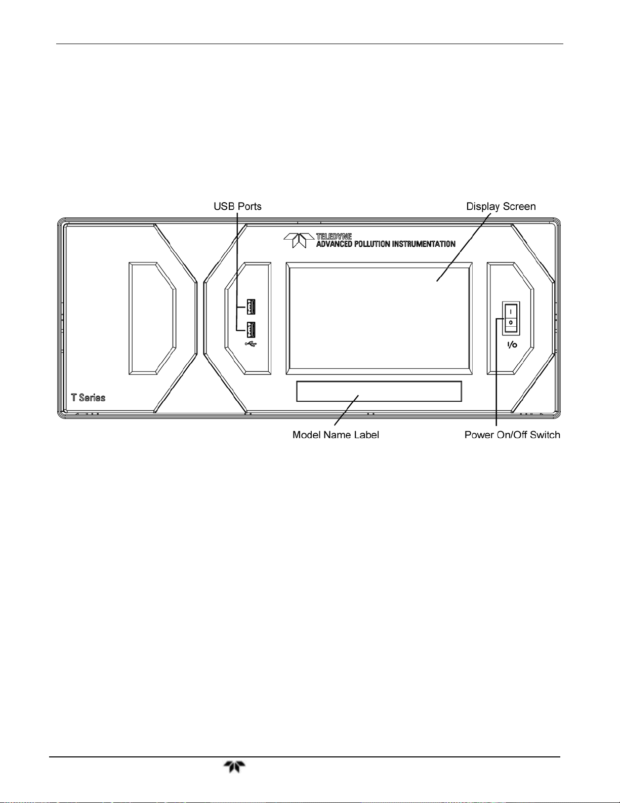
Model 9110TH NOx Analyzer Getting Started
3.2.1. FRONT PANEL
Figure 3-1 shows the analyzer’s front panel layout, followed by a close-up of the display screen in
Figure 3-2, which is described in Table 3-2. The two USB ports on the front panel are provided for the
connection of peripheral devices:
plug-in mouse (not included) to be used as an alternative to the touchscreen interface
thumb drive (not included) to download updates to instruction software (contact TAPI Customer
Service for information).
Figure 3-1: Front Panel Layout
Teledyne Analytical Instruments 33
Page 34

Model 9110T NOx Analyzer Getting Started
The front panel liquid crystal display screen includes touch control. Upon analyzer start-up, the screen
shows a splash screen and other initialization indicators before the main display appears, similar to
Figure 3-2 above. The LEDs on the display screen indicate the Sample, Calibration and Fault states; also
on the screen is the gas concentration field (Conc), which displays real-time readouts for the primary
gases, NO, NO
mode the analyzer is currently in, as well as messages and data (Param). Along the bottom of the screen
is a row of touch control buttons; only those that are currently applicable will have a label. Table 3-2
provides detailed information for each component of the screen.
ATTENTION
Figure 3-2: Display Screen and Touch Control
, and NOx, and for the secondary gas if installed. The display screen also shows what
2
COULD DAMAGE INSTRUMENT AND VOID WARRANTY
Do not use hard-surfaced instruments such as pens to touch the control
buttons.
Teledyne Analytical Instruments 34
Page 35

Model 9110TH NOx Analyzer Getting Started
Table 3-2: Display Screen and Touch Control Description
Field Description/Function
Status LEDs indicating the states of Sample, Calibration and Fault, as follows:
Name Color State Definition
Off
On
SAMPLE Green
CAL Yellow
FAULT Red
Conc
Mode Displays the name of the analyzer’s current operating mode
Param
Control Buttons Displays dynamic, context sensitive labels on each button, which is blank when inactive until applicable.
Displays the actual concentration of the sample gas currently being measured by the analyzer in the
currently selected units of measure.
Displays a variety of informational messages such as warning messages, operational data, test function
values and response messages during interactive tasks.
Blinking
Off
On
Blinking
Off
Blinking
Unit is not operating in sample mode, DAS is disabled.
Sample Mode active; Front Panel Display being updated; DAS data
being stored.
Unit is operating in sample mode, front panel display being updated,
DAS hold-off mode is ON, DAS disabled
Auto Cal disabled
Auto Cal enabled
Unit is in calibration mode
No warnings exist
Warnings exist
Figure 3-3 shows how the front panel display is mapped to the menu charts illustrated in this manual.
The Mode, Param (parameters), and Conc (gas concentration) fields in the display screen are
represented across the top row of each menu chart. The eight touch control buttons along the bottom of
the display screen are represented in the bottom row of each menu chart.
Teledyne Analytical Instruments 35
Page 36

Model 9110T NOx Analyzer Getting Started
Figure 3-3: Display/Touch Control Screen Mapped to Menu Charts
Note
The menu charts in this manual contain condensed representations of the
analyzer’s display during the various operations being described. These
menu charts are not intended to be exact visual representations of the
actual display.
Teledyne Analytical Instruments 36
Page 37

Model 9110TH NOx Analyzer Getting Started
3.2.2. REAR PANEL
Figure 3-4: Rear Panel Layout – Base Unit
Table 3-3 provides a description of each component on the rear panel.
Teledyne Analytical Instruments 37
Page 38

Model 9110T NOx Analyzer Getting Started
Table 3-3: Rear Panel Description
Component Function
cooling fan
AC power
connector
Model/specs label
TO CONV
FROM CONV
MULTI
TO DRYER
FROM DRYER
SAMPLE
EXHAUST
SPAN 1
SPAN2/VENT
ZERO AIR
RX TX
COM 2
RS-232
DCE DTE
STATUS
ANALOG OUT
CONTROL IN
ALARM
ETHERNET
ANALOG IN
USB
Model Label
Pulls ambient air into chassis through side vents and exhausts through rear.
Connector for three-prong cord to apply AC power to the analyzer.
CAUTION! The cord’s power specifications (specs) MUST comply with the power
specs on the analyzer’s rear panel Model number label
Identifies the analyzer model number and provides power specs
(not used)
(not used)
(not used)
(not used)
Outlet for internal sample gas dryer; connect to external zero air scrubber (for IZS options
only).
Connect a gas line from the source of sample gas here.
Calibration gases can also enter here on units without zero/span/shutoff valve options
installed.
Connect an exhaust gas line of not more than 10 meters long here that leads outside the
shelter or immediate area surrounding the instrument. The line must be ¼” tubing or
greater.
On units with zero/span/shutoff valves option installed, connect a gas line to the source of
calibrated span gas here.
On units with pressurized span valve option, used for venting.
Internal Zero Air: On units with zero/span/shutoff valves option installed but no internal
zero air scrubber attach a gas line to the source of zero air here.
LEDs indicate receive (RX) and transmit (TX) activity on the when blinking.
Serial communications port for RS-232 or RS-485.
Serial communications port for RS-232 only.
Switch to select either data terminal equipment or data communication equipment during
RS-232 communication.
For ouputs to devices such as Programmable Logic Controllers (PLCs).
For voltage or current loop outputs to a strip chart recorder and/or a data logger.
For remotely activating the zero and span calibration modes.
Option for concentration alarms and system warnings.
Connector for network or Internet remote communication, using Ethernet cable
Option for external voltage signals from other instrumentation and for logging these
signals
Connector for direct connection to laptop computer, using USB cable.
Includes voltage and frequency specifications
3.2.3. INTERNAL CHASSIS LAYOUT
Figure 3-5 and Figure 3-6 show internal chassis configurations with different options.
Teledyne Analytical Instruments 38
Page 39

Model 9110TH NOx Analyzer Getting Started
Figure 3-5: Internal Layout – Top View with IZS Option
Teledyne Analytical Instruments 39
Page 40

Model 9110T NOx Analyzer Getting Started
Figure 3-6: Internal Layout - Top View Showing Other Options
Teledyne Analytical Instruments 40
Page 41

Model 9110TH NOx Analyzer Getting Started
3.3. CONNECTIONS AND SETUP
This section presents the electrical (Section 3.3.1) and pneumatic (Section 3.3.2) connections for setup
and preparing for instrument operation.
3.3.1. ELECTRICAL CONNECTIONS
Note To maintain compliance with EMC standards, it is required that the cable
length be no greater than 3 meters for all I/O connections, which include
Analog In, Analog Out, Status Out, Control In, Ethernet/LAN, USB, RS-232,
and RS-485.
This section presents the electrical connections for AC power and communications.
3.3.1.1. Connecting Power
Attach the power cord to the analyzer and plug it into a power outlet capable of carrying at least 10 A
current at your AC voltage and that it is equipped with a functioning earth ground.
WARNING
ELECTRICAL SHOCK HAZARD
High Voltages are present inside the analyzers case.
Power connection must have functioning ground connection.
Do not defeat the ground wire on power plug.
Turn off analyzer power before disconnecting or
connecting electrical subassemblies.
Do not operate with cover off.
CAUTION
GENERAL SAFETY HAZARD
The 9110T analyzer can be configured for both
100-130 V and 210-240 V at either 47 or 63 Hz.
To avoid damage to your analyzer, ensure that the AC power voltage
matches the voltage indicated on the analyzer’s model/specs label (Figure
3-4) before plugging the 9110T into line power.
3.3.1.2. Connecting Analog Inputs (Option)
The Analog In connector is used for connecting external voltage signals from other instrumentation
(such as meteorological instruments) and for logging these signals in the analyzer’s internal DAS. The
input voltage range for each analog input is 0-10 VDC.
Teledyne Analytical Instruments 41
Page 42

Model 9110T NOx Analyzer Getting Started
Figure 3-7: Analog In Connector
Pin assignments for the Analog In connector are presented in Table 3-4.
PIN DESCRIPTION
1 Analog input # 1 AIN 1
2 Analog input # 2 AIN 2
3 Analog input # 3 AIN 3
4 Analog input # 4 AIN 4
5 Analog input # 5 AIN 5
6 Analog input # 6 AIN 6
7 Analog input # 7 AIN 7
8 Analog input # 8 AIN 8
GND Analog input Ground N/A
1
See Section 7 for details on setting up the DAS.
3.3.1.3. Connecting Analog Outputs
Table 3-4: Analog Input Pin Assignments
DAS
PARAMETER
1
The 9110T is equipped with several analog output channels accessible through a connector on the back
panel of the instrument.
Output channels A1, A2 and A3 are assigned to the NO
, NO and NO2 concentration signals of the
x
analyzer.
The default analog output voltage setting of these channels is 0 to 5 VDC with a reporting
range of 0 to 500 ppb.
An optional Current Loop output is available for each.
The output labeled A4 is special. It can be set by the user to output any one a variety of diagnostic test
functions (see Section 5.9.4).
The default analog output voltage setting of these channels is also 0 to 5 VDC.
See Section 5.9.4 for a list of available functions and their associated reporting range.
There is no optional Current Loop output available for Channel A4.
To access these signals attach a strip chart recorder and/or data-logger to the appropriate analog output
connections on the rear panel of the analyzer. Pin-outs for the analog output connector are:
Teledyne Analytical Instruments 42
Page 43

Model 9110TH NOx Analyzer Getting Started
ANALOG OUT
A1 A2 A3 A4
+ - + - + - + -
Figure 3-8: Analog Output Connector
Table 3-5: Analog Output Pin Assignments
PIN ANALOG OUTPUT SIGNAL
1
2 Ground I Out -
3
4 Ground I Out -
3
4 Ground I Out -
7
8 Ground Not Available
A1
A2
A3
A4
1
NOx Concentration
NO Concentration
NO2 Concentration
TEST CHANNEL
VOLTAGE OUTPUT
To change the settings for the analog output channels, see Section 5.9.2.
3.3.1.4. Current Loop Analog Outputs (Option 41) Setup
If your analyzer had this option installed at the factory, there are no further connectons to be made.
Otherwise, it can be installed as a retrofit for each of the analog outputs of the analyzer . This option
converts the DC voltage analog output to a current signal with 0-20 mA output current. The outputs can
be scaled to any set of limits within that 0-20 mA range. However, most current loop applications call
for either 2-20 mA or 4-20 mA range. All current loop outputs have a +5% over-range. Ranges with the
lower limit set to more than 1 mA (e.g., 2-20 or 4-20 mA) also have a -5% under-range.
STANDARD
V Out I Out +
V Out I Out +
V Out I Out +
V Out Not Available
CURRENT
LOOP OPTION
Figure 3-9 provides installation instructions and illustrates a sample combination of one current output
and two voltage outputs configuration. This section provides instructions for converting current loop
analog outputs to standard 0-to-5 VDC outputs. Information on calibrating or adjusting these outputs can
be found in Section 5.9.3.7.
CAUTION – AVOID INVALIDATING WARRANTY
Servicing or handling of circuit components requires electrostatic
discharge protection, i.e. ESD grounding straps, mats and containers.
Failure to use ESD protection when working with electronic assemblies will
void the instrument warranty. Refer to Section 14 for more information on
preventing ESD damage.
Teledyne Analytical Instruments 43
Page 44

Model 9110T NOx Analyzer Getting Started
Figure 3-9: Current Loop Option Installed on the Motherboard
CONVERTING CURRENT LOOP ANALOG OUTPUTS TO STANDARD VOLTAGE OUTPUTS
To convert an output configured for current loop operation to the standard 0 to 5 VDC output operation:
1. Turn off power to the analyzer.
8. If a recording device was connected to the output being modified, disconnect it.
9. Remove the top cover.
Remove the set screw located in the top, center of the rear panel.
Remove the screws fastening the top cover to the unit (one per side).
Slide the cover back and lift the cover straight up.
10. Remove the screw holding the current loop option to the motherboard.
11. Disconnect the current loop option PCA from the appropriate connector on the
motherboard (see Figure 3-9).
12. Each connector, J19 and J23, requires two shunts. Place one shunt on the two left
most pins and the second shunt on the two adjacent pins (see Figure 3-9).
13. Reattach the top case to the analyzer.
Teledyne Analytical Instruments 44
Page 45

Model 9110TH NOx Analyzer Getting Started
The analyzer is now ready to have a voltage-sensing, recording device attached to that output.
Calibrate the analog output as described in Section 5.9.3.2.
3.3.1.5. Connecting the Status Outputs
The status outputs report analyzer conditions via optically isolated NPN transistors, which sink up to 50
mA of DC current. These outputs can be used interface with devices that accept logic-level digital
inputs, such as Programmable Logic Controllers (PLCs). Each Status bit is an open collector output that
can withstand up to 40 VDC. All of the emitters of these transistors are tied together and available at pin
D.
ATTENTION
The status outputs are accessed via a 12-pin connector on the analyzer’s rear panel labeled STATUS
(Figure 3-4). Pin-outs for this connector are:
COULD DAMAGE INSTRUMENT AND VOID WARRANTY
Most PLC’s have internal provisions for limiting the current that the input
will draw from an external device. When connecting to a unit that does
not have this feature, an external dropping resistor must be used to limit
the current through the transistor output to less than 50 mA. At 50 mA,
the transistor will drop approximately 1.2V from its collector to emitter.
1 2 3 4 5 6 7 8 D +
SYSTEM OK
CONC VALID
HIGH RANGE
STATUS
ZERO CAL
CAL
2
O
SPAN CAL
DIAG MODE
+5V to external device
Figure 3-10: Status Output Connector
Table 3-6: Status Output Pin Assignments
OUTPUT # STATUS DEFINITION CONDITION
1
2
3
4
5
SYSTEM OK
CONC VALID
HIGH RANGE
ZERO CAL
SPAN CAL
On if no faults are present.
On if O3 concentration measurement is valid.
If the O
On if unit is in high range of DUAL or AUTO Range Modes.
On whenever the instrument is in CALZ mode.
On whenever the instrument is in CALS mode.
concentration measurement is invalid, this bit is OFF.
3
Teledyne Analytical Instruments 45
Page 46
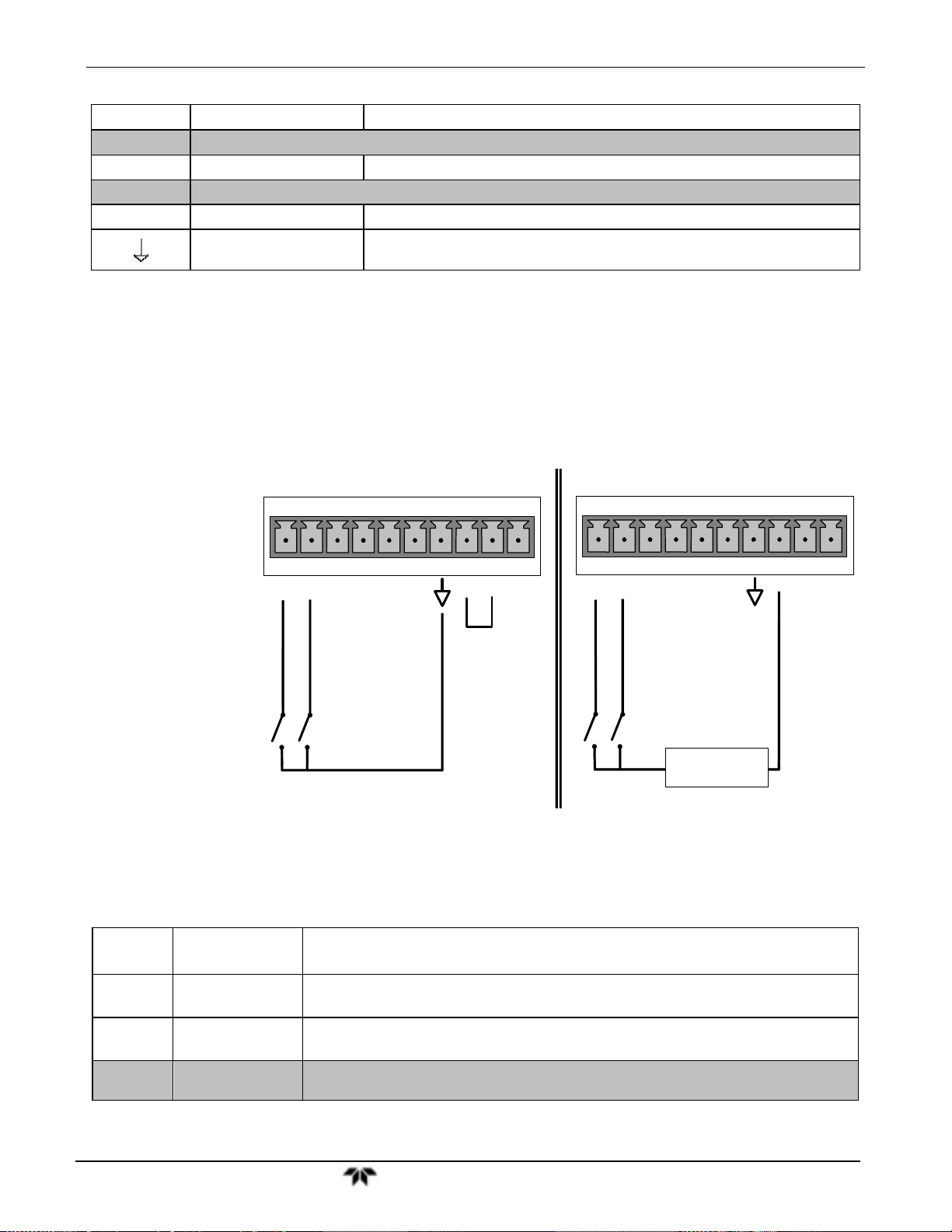
Model 9110T NOx Analyzer Getting Started
6
7-8
D Emitter BUS The emitters of the transistors on pins 1 to 8 are bussed together.
SPARE
+ DC Power
DIAG MODE
Digital Ground
On whenever the instrument is in DIAGNOSTIC mode.
+ 5 VDC, 300 mA source maximum
The ground level from the analyzer’s internal DC power supplies. This
connection should be used as the ground return when +5VDC power is used.
3.3.1.6. Connecting the Control Inputs
The analyzer is equipped with three digital control inputs that can be used to remotely activate the zero
and span calibration modes (see Section 9.1.2.4). Access to these inputs is provided via a 10-pin
connector labeled CONTROL IN on the analyzer’s rear panel.
There are two methods for energizing the Control Inputs. The internal +5V available from the pin
labeled “+” is the most convenient method however, to ensure that these inputs are truly isolated; a
separate external 5 VDC power supply should be used.
CONTROL IN
SPARE
CONTROL IN
Input #
A
B
C, D, E
& F
A B C D E F U
Status
Definition
REMOTE
ZERO CAL
REMOTE
SPAN CAL
Spare
+
ZERO
SPAN
Local Power Connections
A B C D E F U
ZERO
SPAN
-
5 VDC Power
Supply
External Power Connections
Figure 3-11: Energizing the 9110T Control Inputs
Table 3-7: Control Input Pin Assignments
ON Condition
The Analyzer is placed in Zero Calibration mode. The mode field of the display will
read ZERO CAL R.
The Analyzer is placed in Lo Span Calibration mode. The mode field of the display will
read SPAN CAL R.
+
+
Teledyne Analytical Instruments 46
Page 47
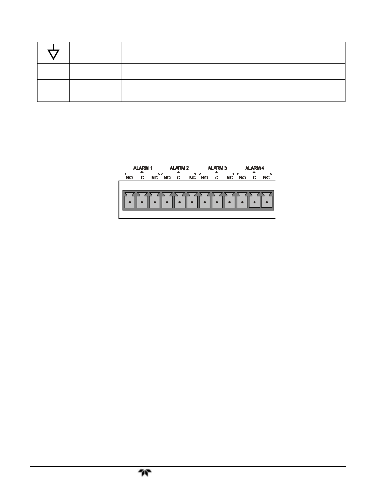
Model 9110TH NOx Analyzer Getting Started
Digital Ground
U
+
External Power
input
5 VDC output
The ground level from the analyzer’s internal DC Power Supplies (same as chassis
ground).
Input pin for +5 VDC required to activate pins A – F.
Internally generated 5V DC power. To activate inputs A – F, place a jumper between
this pin and the “U” pin. The maximum amperage through this port is 300 mA
(combined with the analog output supply, if used).
3.3.1.7. Concentration Alarm Relay (Option 61)
The TAI “E” series analyzers have an option for four (4) “dry contact” relays on the rear panel of the
instrument. This relay option is different from and in addition to the “Contact Closures” that come
standard on all TAPI instruments. The relays have 3 pins that have connections on the rear panel (refer
Figure 3-12). They are a Common (C), a Normally Open (NO), & a Normally Closed (NC) pin.
Figure 3-12: Concentration Alarm Relay
Alarm 1 “System OK 2”
Alarm 2 “Conc 1”
Alarm 3 “Conc 2”
Alarm 4 “Range Bit”
“ALARM 1” RELAY
Alarm 1 which is “System OK 2” (system OK 1, is the status bit) is in the energized state when the
instrument is “OK” & there are no warnings. If there is a warning active or if the instrument is put into
the “DIAG” mode, Alarm 1 will change states. This alarm has “reverse logic” meaning that if you put a
meter across the Common & Normally Closed pins on the connector you will find that it is OPEN when
the instrument is OK. This is so that if the instrument should turn off or lose power, it will change states
& you can record this with a data logger or other recording device.
“ALARM 2” RELAY & “ALARM 3” RELAY
The “Alarm 2 Relay” on the rear panel, is associated with the “Concentration Alarm 1” set point in the
software & the “Alarm 3 Relay” on the rear panel is associated with the “Concentration Alarm 2” set
point in the software.
Alarm 2 Relay NO Alarm 1 = xxx PPM
Teledyne Analytical Instruments 47
Page 48

Model 9110T NOx Analyzer Getting Started
Alarm 3 Relay NO2 Alarm 2 = xxx PPM
Alarm 2 Relay NOX Alarm 1 = xxx PPM
Alarm 3 Relay NOX Alarm 2 = xxx PPM
The Alarm 2 Relay will be turned on any time the concentration set-point is exceeded & will return to its
normal state when the concentration value goes back below the concentration set-point.
Even though the relay on the rear panel is a NON-Latching alarm & resets when the concentration goes
back below the alarm set point, the warning on the front panel of the instrument will remain latched until
it is cleared. You can clear the warning on the front panel by either pushing the CLR button on the front
panel or through the serial port.
In instruments that sample more than one gas type, there could be more than one gas type triggering the
Concentration 1 Alarm (“Alarm 2” Relay). For example, the 9110T instrument can monitor both NO &
NO
gas. The software for this instrument is flexible enough to allow you to configure the alarms so that
2
you can have 2 alarm levels for each gas.
NO Alarm 1 = 20 PPM
In this example, NO Alarm 1 & NO2 Alarm 1 will both be associated with the “Alarm 2” relay on the
rear panel. This allows you do have multiple alarm levels for individual gases.
A more likely configuration for this would be to put one gas on the “Alarm 1” relay and the other gas on
the “Alarm 2” relay.
“ALARM 4” RELAY
NO Alarm 2 = 100 PPM
NO2 Alarm 1 = 20 PPM
NO2 Alarm 2 = 100 PPM
NO Alarm 1 = 20 PPM
NO
Alarm 2 = Disabled
NO
Alarm 1 = Disabled
2
NO
Alarm 2 = 100 PPM
2
This relay is connected to the “range bit”. If the instrument is configured for “Auto Range” and the
instrument goes up into the high range, it will turn this relay on.
3.3.1.8. Connecting the Communications Interfaces
The T-Series analyzers are equipped with connectors for remote communications interfaces: Ethernet,
USB, RS-232, RS-232 Multidrop and RS-485 (each described here). In addition to using the
Teledyne Analytical Instruments 48
Page 49

Model 9110TH NOx Analyzer Getting Started
appropriate cables, each type of communication method, must be configured using the SETUP>COMM
menu (see Sections 5.7 and 6).
ETHERNET CONNECTION
For network or Internet communication with the analyzer, connect an Ethernet cable from the analyzer’s
rear panel Ethernet interface connector to an Ethernet port. Although the analyzer is shipped with DHCP
enabled by default (Section 6.5.2), it should be manually assigned a static IP address.
Configuration: (manual, i.e., static) Section 6.5.1.
USB CONNECTION
The USB option can be used for direct communication between the analyzer and a PC; connect a USB
cable between the analyzer and computer USB ports. Baud rates must match: check the baud rate on
either the computer or the instrument and change the other to match (see Section 6.2.2). This USB
connection can only be used when the COM2 port is not in use except for RS-232 Multidrop
communication.
Configuration: Section 6.6.
Note If this option is installed, the rear panel COM2 port cannot be used for
anything other than Multidrop communication.
RS-232 CONNECTION
For RS-232 communications with data terminal equipment (DTE) or with data communication
equipment (DCE) connect either a DB9-female-to-DB9-female cable (TAI part number WR000077) or a
DB9-female-to-DB25-male cable (Option 60A, Section 1.4), as applicable, from the analyzer’s rear
panel RS-232 port to the device. Adjust the DCE-DTE switch (Figure 3-4) to select DTE or DCE as
appropriate (Section 6.1).
Configuration: Section 6.3 and Section 6.7.2 (for Hessen protocol).
IMPORTANT
IMPACT ON READINGS OR DATA
Cables that appear to be compatible because of matching connectors
may incorporate internal wiring that makes the link inoperable. Check
cables acquired from sources other than TAI for pin assignments (Figure
3-13) before using.
Teledyne Analytical Instruments 49
Page 50

Model 9110T NOx Analyzer Getting Started
Figure 3-13 Rear Panel Connector Pin-Outs for RS-232 Mode
The signals from these two connectors are routed from the motherboard via a wiring harness to two 10pin connectors on the CPU card, J11 and J12 (Figure 3-14).
Teledyne Analytical Instruments 50
Page 51

Model 9110TH NOx Analyzer Getting Started
Figure 3-14: Default Pin Assignments for CPU COMM Port Connector (RS-232).
TAI offers two mating cables, one of which should be applicable for your use.
P/N WR000077, a DB-9 female to DB-9 female cable, 6 feet long. Allows connection of the
serial ports of most personal computers.
P/N WR000024, a DB-9 female to DB-25 male cable. Allows connection to the most
common styles of modems (e.g. Hayes-compatible) and code activated switches.
Both cables are configured with straight-through wiring and should require no additional adapters.
Note Cables that appear to be compatible because of matching connectors
may incorporate internal wiring that makes the link inoperable. Check
cables acquired from sources other than TAI for pin assignments before
using.
To assist in properly connecting the serial ports to either a computer or a modem, there are activity
indicators just above the RS-232 port. Once a cable is connected between the analyzer and a computer
or modem, both the red and green LEDs should be on.
If the lights are not lit, locate the small switch on the rear panel to switch it between DTE
and DCE modes.
If both LEDs are still not illuminated, ensure that the cable properly constructed.
Received from the factory, the analyzer is set up to emulate an RS-232 DCE device.
Teledyne Analytical Instruments 51
Page 52

Model 9110T NOx Analyzer Getting Started
RS-232 (COM1): RS-232 (fixed) DB-9 male connector
Baud rate: 115200 bits per second (baud)
Data Bits: 8 data bits with 1 stop bit
Parity: None
COM2: RS-232 (configurable to RS 485), DB-9 female connector
Baud rate:19200 bits per second (baud)
Data Bits: 8 data bits with 1 stop bit
Parity: None
RS-232 MULTIDROP (OPTION 62) CONNECTION
When the RS-232 Multidrop option is installed, connection adjustments and configuration through the
menu system are required. This section provides instructions for the internal connection adjustments,
then for external connections, and ends with instructions for menu-driven configuration.
Note Because the RS-232 Multidrop option uses both the RS232 and COM2
DB9 connectors on the analyzer’s rear panel to connect the chain of
instruments, COM2 port is no longer available for separate RS-232 or
RS-485 operation.
ATTENTION
COULD DAMAGE INSTRUMENT AND VOID WARRANTY
Printed Circuit Assemblies (PCAs) are sensitive to electro-static
discharges too small to be felt by the human nervous system. Failure to
use ESD protection when working with electronic assemblies will void
the instrument warranty. Refer to Section 14 for more information on
preventing ESD damage.
In each instrument with the Multidrop option there is a shunt jumpering two pins on the serial Multidrop
and LVDS printed circuit assembly (PCA), as shown in Figure 3-15. This shunt must be removed from
all instruments except that designated as last in the multidrop chain, which must remain terminated. This
requires powering off and opening each instrument and making the following adjustments:
1. With NO power to the instrument, remove its top cover and lay the rear panel open
for access to the Multidrop/LVDS PCA, which is seated on the CPU.
2. On the Multidrop/LVDS PCA’s JP2 connector, remove the shunt that jumpers Pins
21 22 as indicated in. (Do this for all but the last instrument in the chain where
the shunt should remain at Pins 21 22).
3. Check that the following cable connections are made in all instruments (again refer
to Figure 3-15):
J3 on the Multidrop/LVDS PCA to the CPU’s COM1 connector
Teledyne Analytical Instruments 52
Page 53

Model 9110TH NOx Analyzer Getting Started
1. (Note that the CPU’s COM2 connector is not used in Multidrop)
J4 on the Multidrop/LVDS PCA to J12 on the motherboard
J1 on the Multidrop/LVDS PCS to the front panel LCD
Figure 3-15: Jumper and Cables for Multidrop Mode
2. (Note: If you are adding an instrument to the end of a previously configured chain,
remove the shunt between Pins 21 22 of JP2 on the Multidrop/LVDS PCA in the
instrument that was previously the last instrument in the chain.)
4. Close the instrument.
5. Referring to Figure 3-16 use straight-through DB9 male DB9 female cables to
interconnect the host RS232 port to the first analyzer’s RS232 port; then from the
first analyzer’s COM2 port to the second analyzer’s RS232 port; from the second
analyzer’s COM2 port to the third analyzer’s RS232 port, etc., connecting in this
fashion up to eight analyzers, subject to the distance limitations of the RS-232
standard.
6. On the rear panel of each analyzer, adjust the DCE DTE switch so that the green
and the red LEDs (RX and TX) of the COM1 connector (labeled RS232) are both
lit. (Ensure you are using the correct RS-232 cables internally wired specifically for
RS-232 communication; see Table 1-1, “Communication Cables” and Section
3.3.1.8: Connecting the Communications Interfaces, “RS-232 Connection”).
Teledyne Analytical Instruments 53
Page 54

Model 9110T NOx Analyzer Getting Started
Host
RS-232 port
Analyzer Analyzer Analyzer Last Analyzer
COM2
RS-232
COM2
RS-232
COM2
RS-232
Female DB9
Male DB9
COM2
RS-232
Ensure jumper is
installed between
JP2 pins 21
last instrument of
multidrop chain.
22 in
Figure 3-16: RS-232-Multidrop PCA Host
7. BEFORE communicating from the host, power on the instruments and check that
the Machine ID code is unique for each (Section 5.7.1).
3. a. In the SETUP Mode menu go to SETUP>MORE>COMM>ID. The
default ID is typically the model number or “0”.
4. b. to change the identification number, press the button below the digit to
be changed.
5. c. Press/select ENTER to accept the new ID for that instrument.
8. Next, in the SETUP>MORE>COMM>COM1 menu (do not use the COM2 menu for
multidrop), edit the COM1 MODE parameter as follows: press/select EDIT and set
only QUIET MODE, COMPUTER MODE, and MULTIDROP MODE to ON. Do not
change any other settings.
9. Press/select ENTER to accept the changed settings, and ensure that COM1 MODE
now shows 35.
10. Press/select SET> to go to the COM1 BAUD RATE menu and ensure it reads the
same for all instruments (edit as needed so that all instruments are set at the same
baud rate).
/Analyzer Interconnect Diagram
Note
The (communication) Host instrument can address only one instrument at a
time, each by its unique ID (see step 7 above).
Teledyne Analytical Instruments 54
Page 55

Model 9110TH NOx Analyzer Getting Started
Note
RS-485 CONNECTION
TAI recommends setting up the first link, between the Host and the first analyzer,
and testing it before setting up the rest of the chain.
As delivered from the factory, COM2 is configured for RS-232 communications. This port can be
reconfigured for operation as a non-isolated, half-duplex RS-485 port. Using COM2 for RS-485
communication will disable the USB port. To reconfigure this port for RS-485 communication, please
contact the factory.
3.3.2. PNEUMATIC CONNECTIONS
This section provides not only pneumatic connection information, but also important information about
the gases required for accurate calibration (Section 3.3.2.1); it also illustrates the pneumatic layouts for
the analyzer in its basic configuration and with options.
Before making the pneumatic connections, carefully note the following cautionary and additional
messages:
Do not vent calibration gas or sample gas into enclosed areas.
CAUTION
GENERAL SAFETY HAZARD
IMPORTANT
CAUTION – GENERAL SAFETY HAZARD
In units with a permeation tube option installed, vacuum pump must be
connected and powered on to maintain constant gas flow though the
analyzer at all times. Insufficient gas flow allows gas to build up to levels
that will contaminate the instrument or present a safety hazard to
personnel.
Remove permeation tube when taking analyzer out of operation, and store
in sealed container (use original container that tube was shipped in).
(See Figure 3-6 for location and Section 11.3.6 for instructions on how to
remove the perm tube when the unit is not in operation).
IMPACT ON READINGS OR DATA
Sample and calibration gases should only come into contact with PTFE
tubing.
Teledyne Analytical Instruments 55
Page 56

Model 9110T NOx Analyzer Getting Started
ATTENTION
IMPORTANT
COULD DAMAGE INSTRUMENT AND VOID WARRANTY
Venting Pressurized Gas:
In applications where any gas (span gas, zero air supply, sample gas) is
received from a pressurized manifold, a vent must be provided to equalize
the gas with ambient atmospheric pressure before it enters the analyzer to
ensure that the gases input do not exceed the maximum inlet pressure of
the analyzer, as well as to prevent back diffusion and pressure effects.
These vents should be:
• at least 0.2m long
• no more than 2m long
• vented outside the shelter or immediate area surrounding the instrument.
Dust Plugs:
Remove dust plugs from rear panel exhaust and supply line fittings before
powering on/operating instrument. These plugs should be kept for reuse in
the event of future storage or shipping to prevent debris from entering the
pneumatics.
Leak Check:
Run a leak check once the appropriate pneumatic connections have
been made; check all pneumatic fittings for leaks using the
procedures defined in Section 11.3.12.1.
3.3.2.1. About Zero Air and Calibration (Span) Gas
Zero air and span gas are required for accurate calibration.
Note Zero air and span gases must be supplied at twice the instrument’s
specified gas flow rate. Therefore, the 9110T zero and span gases should
be supplied to their respective inlets in excess of 1000 cc3/min (500
cc3/min x 2).
ZERO AIR
Zero air or zero calibration gas is defined as a gas that is similar in chemical composition to the
measured medium but without the gas to be measured by the analyzer.
For the 9110T this means zero air should be devoid of NO, NO
Note Moderate amounts of NH3 and H2O can be removed from the sample gas
stream by installing the optional sample gas dryer/scrubber (see Section
3.3.2.6).
If your application is not a measurement in ambient air, the zero calibration gas should be matched
to the composition of the gas being measured.
, CO2, NH3 or H2O vapor.
2
Teledyne Analytical Instruments 56
Page 57

Model 9110TH NOx Analyzer Getting Started
Pure nitrogen (N2) could be used as a zero gas for applications where NOX is measured in nitrogen.
If your analyzer is equipped with an external zero air scrubber option, it is capable of creating zero
air from ambient air.
For analyzers without the external zero air scrubber, a zero air generator such as the Teledyne
Model 701 can be used. Please visit the company website for more information.
CALIBRATION (SPAN) GAS
Calibration gas is a gas specifically mixed to match the chemical composition of the type of gas being
measured at near full scale of the desired reporting range. To measure NO
analyzer, it is recommended that you use a span gas with an NO concentration equal to 80% of the
measurement range for your application
EXAMPLE:
If the application is to measure NOX in ambient air between 0 ppm and 500 ppb, an appropriate
span gas would be 400 ppb.
If the application is to measure NOX in ambient air between 0 ppm and 1000 ppb, an appropriate
span gas would be 800 ppb.
with the 9110T NO
X
X
Even though NO gas in nitrogen could be used as a span gas, the matrix of the balance gas is different
and may cause interference problems or yield incorrect calibrations.
The same applies to gases that contain high concentrations of other compounds (for example, CO2
or H2O).
The span gas should match all concentrations of all gases of the measured medium as closely as
possible.
Cylinders of the following types of calibrated NOx and NO gas traceable to NIST standards specifications
(also referred to as EPA protocol calibration gases or Standard Reference Materials) are commercially
available.
Table 3-8: NIST-SRM's Available for Traceability of NOx Calibration Gases
NIST-SRM4 TYPE
2627a
2628a
2629a
1683b
1684b
1685b
1686b
1687b
2630
2631a
2635
2636a
2631a
1684b
Nitric Oxide (NO) in N
Nitric Oxide (NO) in N
Nitric Oxide (NO) in N2
Nitric Oxide (NO) in N
Nitric Oxide (NO) in N
Nitric Oxide (NO) in N
Nitric Oxide (NO) in N
Nitric Oxide (NO) in N2
Nitric Oxide (NO) in N
Nitric Oxide (NO) in N
Nitric Oxide (NO) in N
Nitric Oxide (NO) in N2
Oxides of Nitrogen (NOx) in N2
Oxides of Nitrogen (NO
2
2
2
2
2
2
2
2
2
) in N2
x
NOMINAL
CONCENTRATION
5 ppm
10 ppm
20 ppm
50 ppm
100 ppm
250 ppm
5000 ppm
1000 ppm
1500 ppm
3000 ppm
800 ppm
2000 ppm
2500 ppm
100 ppm
Note The NO2 permeation tube included with the 9110T’s optional Internal
Teledyne Analytical Instruments 57
Page 58

Model 9110T NOx Analyzer Getting Started
Zero Air generator (IZS) has a limited accuracy of about ±5%.
While NO2 permeation tubes may be sufficient for informal calibration
checks, they are not approved by the US EPA as calibration sources for
performing actual calibration of the analyzer.
SPAN GAS FOR MULTIPOINT CALIBRATION
Some applications, such as EPA monitoring, require a multipoint calibration where span gases of
different concentrations are needed. We recommend using an NO gas of higher concentration combined
with a gas dilution calibrator such as a Teledyne Model 700E. This type of calibrator mixes a high
concentration gas with zero air to accurately produce span gas of the desired concentration. Linearity
profiles can be automated with this model and run unattended overnight.
If a dynamic dilution system such as the Teledyne Model 700 is used to dilute high concentration gas
standards to low, ambient concentrations, ensure that the NO concentration of the reference gas matches
the dilution range of the calibrator.
Choose the NO gas concentration so that the dynamic dilution system operates in its mid-range and not
at the extremes of its dilution capabilities.
EXAMPLE:
A dilution calibrator with 10-10000 dilution ratio will not be able to accurately dilute a 5000 ppm NO
gas to a final concentration of 500 ppb, as this would operate at the very extreme dilution setting.
A 100 ppm NO gas in nitrogen is much more suitable to calibrate the 9110T analyzer (dilution ratio
of 222, in the mid-range of the system’s capabilities).
Teledyne Analytical Instruments 58
Page 59
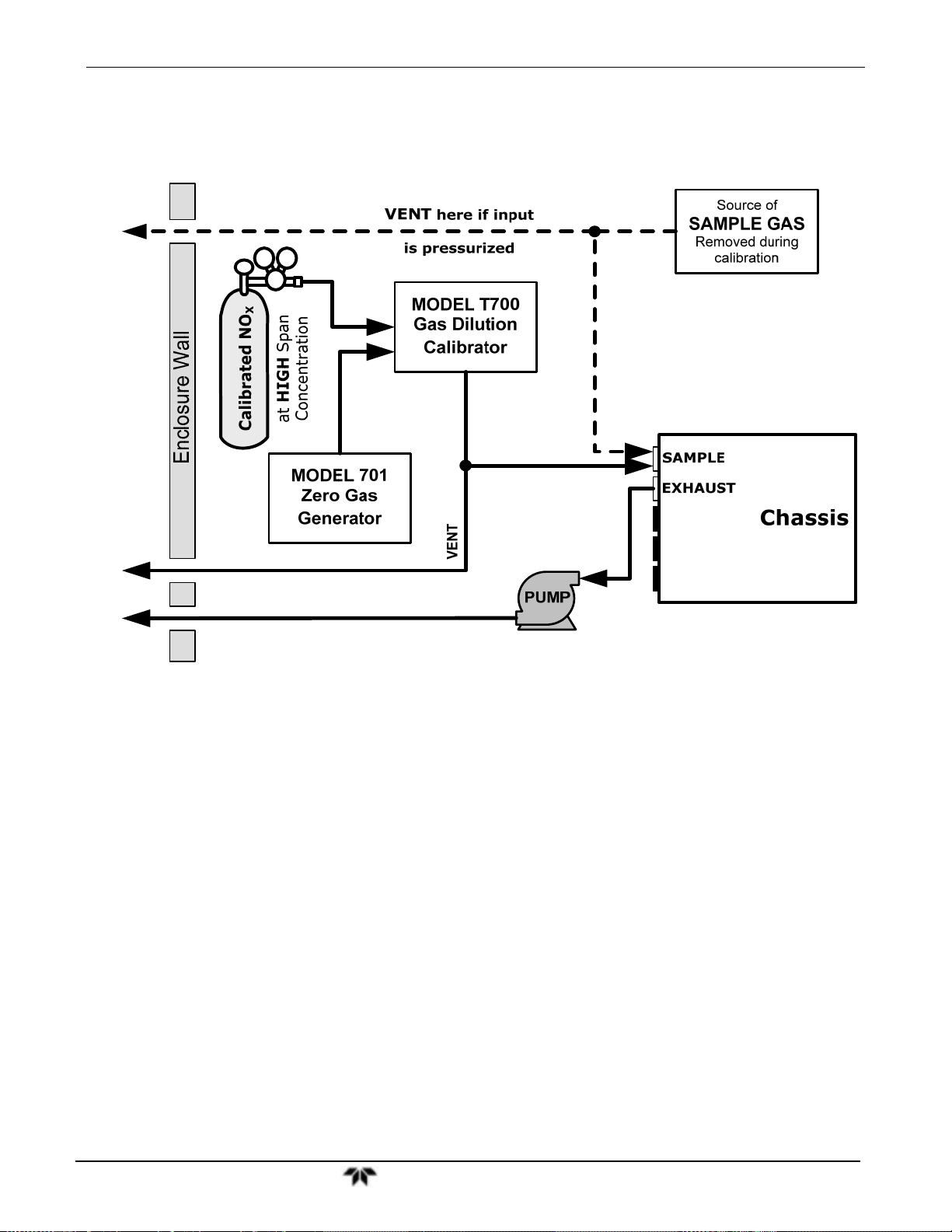
Model 9110TH NOx Analyzer Getting Started
3.3.2.2. Basic Connections from Calibrator, without and With Span Gas
Figure 3-17: Gas Line Connections from Calibrator – Basic 9110T Configuration
Teledyne Analytical Instruments 59
Page 60
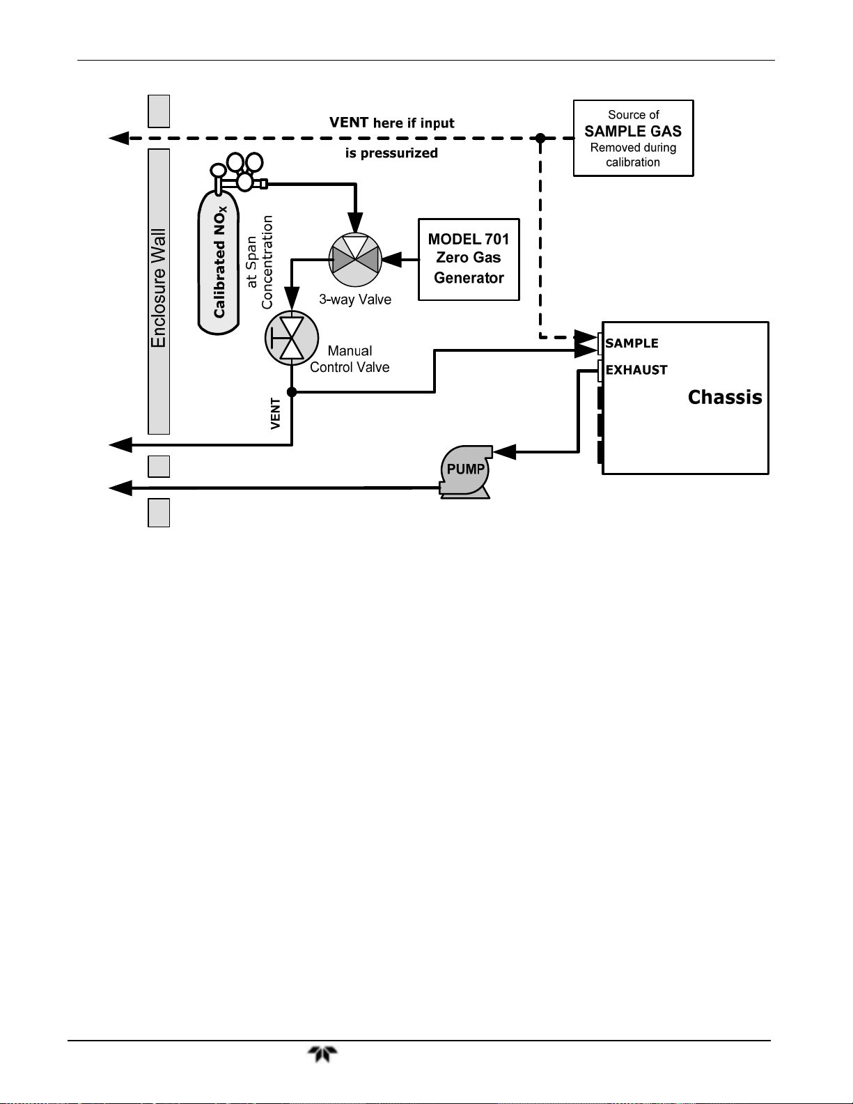
Model 9110T NOx Analyzer Getting Started
Figure 3-18: Gas Line Connections from Bottled Span Gas – Basic 9110T Configuration
For the 9110T nitrogen oxides analyzer in its basic configuration, attach the following pneumatic lines:
SAMPLE GAS SOURCE
Connect a sample gas line to the SAMPLE inlet
Use PTFE tubing; minimum OD ¼”
Sample Gas pressure must equal ambient atmospheric pressure (1.0 psig)
In applications where the sample gas is received from a pressurized manifold and the analyzer is
not equipped with one of the 9110T’s pressurized span options, a vent must be placed on the
sample gas line. This vent line must be:
No more than 10 meters long.
Vented outside the shelter or immediate area surrounding the instrument.
CALIBRATION GAS SOURCES
CAL GAS & ZERO AIR SOURCES: The source of calibration gas is also attached to the SAMPLE
inlet, but only when a calibration operation is actually being performed.
Use PTFE tubing; minimum OD ¼”.
Teledyne Analytical Instruments 60
Page 61

Model 9110TH NOx Analyzer Getting Started
VENTING
In order to prevent back diffusion and pressure effects, both the span gas and zero air supply lines should
be:
Vented outside the enclosure.
Minimum OD ¼”.
Not less than 2 meters in length.
Not greater than 10 meters in length.
EXHAUST OUTLET
Attach an exhaust line to the EXHAUST outlet fitting. The exhaust line should be:
Use PTFE tubing; minimum OD ¼”.
A maximum of 10 meters long.
Vented outside the 9110T analyzer’s enclosure
Note Once the appropriate pneumatic connections have been made, check all
pneumatic fittings for leaks using the procedures defined in Sections
13.3.13.2 (or 13.3.13.3 for detailed check if leak suspected).
PNEUMATIC LAYOUT FOR BASIC CONFIGURATION
Teledyne Analytical Instruments 61
Page 62

Model 9110T NOx Analyzer Getting Started
Figure 3-19: Pneumatics, Basic Configuration
3.3.2.3. Connections w/Ambient Zero/Ambient Span (Z/S) Valves (OPT 50A)
This valve package includes:
Two solenoid valves located inside the analyzer that allow the user to switch either zero, span or
sample gas to the instrument’s sensor.
Two additional gas inlet ports (ZERO AIR and SPAN1).
Teledyne Analytical Instruments 62
Page 63

Model 9110TH NOx Analyzer Getting Started
Figure 3-20: Rear Panel Layout with Z/S Valve Options (OPT 50A)
Figure 3-21: Gas Line Connections for 9110T with Z/S Valves Option (OPT 50A)
SAMPLE GAS SOURCE
Attach a sample inlet line to the SAMPLE inlet fitting.
Use PTFE tubing; minimum O.D ¼”.
Teledyne Analytical Instruments 63
Page 64

Model 9110T NOx Analyzer Getting Started
Sample Gas pressure must equal ambient atmospheric pressure (no greater than 1.0 psig).
In applications where the sample gas is received from a pressurized manifold, a vent must be
placed on the sample gas line. This vent line must be no more than 10 meters long.
CALIBRATION GAS SOURCES
SPAN GAS Attach a gas line from the source of calibration gas (e.g. a Teledyne
M700E Dynamic Dilution Calibrator) to the SPAN1 inlet (see Figure
3-20). Use PTFE tubing; minimum O.D ¼”.
ZERO AIR Zero air is supplied by the zero air generator such as a Teledyne
M701. Attach a gas line from the source of zero air to the ZERO AIR
inlet.
VENTING
In order to prevent back diffusion and pressure effects, both the span gas and zero air supply lines
should be:
Vented outside the enclosure.
Not less than 2 meters in length.
Not greater than 10 meters in length.
EXHAUST OUTLET
Attach an exhaust line to the EXHAUST OUTLET fitting. The exhaust line should be:
¼” PTFE tubing
maximum 10 meters long
Vented outside the 9110T analyzer’s enclosure
Note Once the appropriate pneumatic connections have been made, check all
pneumatic fittings for leaks using the procedures defined in Section
13.3.12.
To find instructions on calibrating a 9110T with this option installed, see
section 10.4.
PNEUMATIC LAYOUT FOR AMBIENT ZERO/AMBIENT SPAN VALVES (OPT 50A)
Teledyne Analytical Instruments 64
Page 65

Model 9110TH NOx Analyzer Getting Started
Figure 3-22: Pneumatics with Zero/Span Valves OPT 50A
Table 3-9: Zero/Span Valves Operating States OPT 50A
MODE VALVE CONDITION
Sample/Cal Open to SAMPLE inlet
SAMPLE
Zero/Span Open to ZERO AIR inlet
Sample/Cal Open to ZERO/SPAN Valve
ZERO CAL
Zero/Span Open to ZERO AIR inlet
Sample/Cal Open to ZERO/SPAN Valve
SPAN CAL
Zero/Span Open to SPAN inlet
VALVE PORT
STATUS
3 2
3 2
1 2
3 2
1 2
1 2
Teledyne Analytical Instruments 65
Page 66

Model 9110T NOx Analyzer Getting Started
3.3.2.4. Connections w/Ambient Zero/Pressurized Span Valves (OpT 50B)
This calibration valve package is appropriate for applications where Span Gas is being supplied from a
pressurized source such as bottled NIST SRM gases. This option includes:
A critical flow orifice and vent that maintains the Span Gas supply at 1 ATM.
A SHUTOFF valve to preserve the Span Gas source when it is not in use.
Two solenoid valves located inside the analyzer that allow the user to switch either zero, span or
sample gas to the instrument’s sensor.
Three additional gas inlet ports (ZERO AIR, SPAN and VENT).
Figure 3-23: Rear Panel Layout with Ambient Zero/Pressurized Span Valves OPT 50B
Teledyne Analytical Instruments 66
Page 67

Model 9110TH NOx Analyzer Getting Started
Figure 3-24: Gas Line Connection w/Ambient Zero/Pressurized Span Valves (OPT 50B)
SAMPLE GAS SOURCE
Attach a sample inlet line to the SAMPLE inlet fitting.
Use PTFE tubing; minimum O.D ¼”.
Sample Gas pressure must equal ambient atmospheric pressure (29.92 in-Hg).
In applications where the sample gas is received from a pressurized manifold, a vent must be
placed on the sample gas line. This vent line must be:
No more than 10 meters long.
Vented outside the shelter or immediate area surrounding the instrument.
CALIBRATION GAS SOURCES
SPAN GAS Attach a gas line from the pressurized source of calibration gas (e.g. a
ZERO AIR (the dual-stage zero Air Scrubber makes zero air)
bottle of NISTSRM gas) to the SPAN1 inlet.. Use PTFE tubing;
minimum O.D ¼”.
VENTING
Attach a line to the SPAN2/VENT outlet. It should be:
¼” PTFE tubing.
Teledyne Analytical Instruments 67
Page 68

Model 9110T NOx Analyzer Getting Started
Vented outside the enclosure.
Not less than 2 meters in length.
Not greater than 10 meters in length.
EXHAUST OUTLET
Attach an exhaust line to the EXHAUST outlet fitting. The exhaust line should be:
¼” PTFE tubing.
A maximum of 10 meters long.
Vented outside the 9110T analyzer’s enclosure.
PNEUMATIC LAYOUT FOR AMBIENT ZERO/PRESSURIZED SPAN (OPT 50B)
Figure 3-25: Pneumatics with Ambient Zero/Pressurized Span Valves (OPT 50B)
Teledyne Analytical Instruments 68
Page 69

Model 9110TH NOx Analyzer Getting Started
Table 3-10: Valve Operating States OPT 50B installed
MODE VALVE CONDITION
Sample/Cal Open to SAMPLE inlet
SAMPLE
ZERO CAL
SPAN CAL
Zero/Span Open to ZERO AIR inlet
Span Shutoff
Zero Air Shutoff
Sample/Cal Open to ZERO/SPAN Valve
Zero/Span Open to ZERO AIR inlet
Span Shutoff
Zero Air Shutoff1
Sample/Cal Open to ZERO/SPAN Valve
Zero/Span Open to SPAN inlet
Span Shutoff
Zero Air Shutoff
Closed
Closed
OPEN
Closed
Closed
OPEN
3.3.2.5. Zero Scrubber and Internal Span Source (IZS) (OPT 50G)
The 9110T nitrogen oxides analyzer can also be equipped with an internal NO2 span gas generator and
calibration valve option. This option package is intended for applications where there is a need for
frequent automated calibration checks without access to an external source of span gas.
This valve package includes:
VALVE PORT
STATUS
3 2
3 2
1 2
3 2
1 2
1 2
A 2-stage external scrubber for producing zero air.
®
50% Purafil Chemisorbant
50% charcoal (for removal of the NO
A heated enclosure for a NO
permeation tube.
2
(for conversion of NO NO2).
).
2
This option package DOES NOT contain an actual permeation tube. See
Section 1.4 (Options 52B and 52G) for information on specifying the correct
permeation tube for each application.
A special desorber that removes all HNO
from the calibration gas stream.
3
One additional gas inlet port (ZERO AIR).
One additional gas outlet port (FROM DRYER).
Two internal valves for switching between the sample gas inlet and the output of the zero/span
subsystem.
Teledyne Analytical Instruments 69
Page 70

Model 9110T NOx Analyzer Getting Started
Figure 3-26: Rear Panel Layout with Internal Span Source (IZS) OPT 50G
INTERNAL SPAN GAS GENERATION
The primary component of the internal span option is a permeation tube containing liquid NO
air is passed over a permeable membrane on the end of the tube, molecules of NO
the membrane mixing with the zero air.
The resulting concentration of the NO
Size of the membrane: The larger the area of the membrane, the more permeation occurs.
Temperature of the NO
: Increasing the temperature of the permeation tube increases the pressure
2
inside the tube and therefore increases the rate of permeation.
Flow rate of the zero air: If the previous two variables are constant, the permeation rate of the NO
into the zero air stream will be constant. Therefore, a lower flow rate of zero air produces higher
concentrations of NO
.
2
In the Model 9110T the permeation tube enclosure is heated to a constant 50° C (10° above the
maximum operating temperature of the instrument) in order to keep the permeation rate constant. A
thermistor measures the actual temperature and reports it to the CPU for control feedback.
The flow rate of zero air across the permeation tube is maintained at 50 ± 10 cm³/min by a critical flow
orifice located in the analyzer’s exhaust manifold.
span gas is determined by three factors:
2
As zero
2.
slowly pass through
2
2
NITRIC ACID AND THE CHEMISTRY OF NO2 PERMEATION TUBES
The reaction of H2O with NO2 to form HNO3 (nitric acid) takes place whenever water and NO2 are
present in the same gas mixture. In the 9110T this is mitigated as much as possible by passing the air
supply for the span gas generator through a special dryer, however the permeable membrane of the NO
tube will still allow H
higher concentrations. Over time this results in the presence of HNO
exuded into the 9110T’s pneumatics along with NO
O from the ambient environment to slowly collect in the tube at increasingly
2
in the permeation tube which is
3
.
2
2
Teledyne Analytical Instruments 70
Page 71

Model 9110TH NOx Analyzer Getting Started
HNO3 is a liquid at room temperature, so once the HNO3 is released by the permeation tube it condenses
and collects along the 9110T’s wetted surfaces, While liquid HNO
measurements of the Model 9110T, it does give off small amounts of gaseous HNO3 which is
NO
x
converted into NO by the 9110T’s NO
NO converter resulting in an artificially high NO2
x
concentration by 8% to 12%. This is particularly bothersome when 9110T is attempting to measure a
zero point, such as during calibration, since the NO
the majority of the HNO
coating the wetted surfaces has reverted to NO2 and this can take a very long
3
concentration will only reach a true zero point once
2
time.
does not directly effect the quality of
3
The 9110T includes a special HNO
desorbed which eliminates any HNO3 given off by the permeation
3
tube before it can be converted into NO by the analyzer’s converter.
PNEUMATIC LAYOUT FOR ZERO SCRUBBER AND IZS (OPT 50G)
Figure 3-27: Pneumatics with the Internal Span Gas Generator (OPT 50G)
Table 3-11: Internal Span Gas Generator Valve Operating States OPT 50G
MODE VALVE CONDITION
SAMPLE Sample/Cal Open to SAMPLE inlet 3 2
VALVE PORT
STATUS
Teledyne Analytical Instruments 71
Page 72
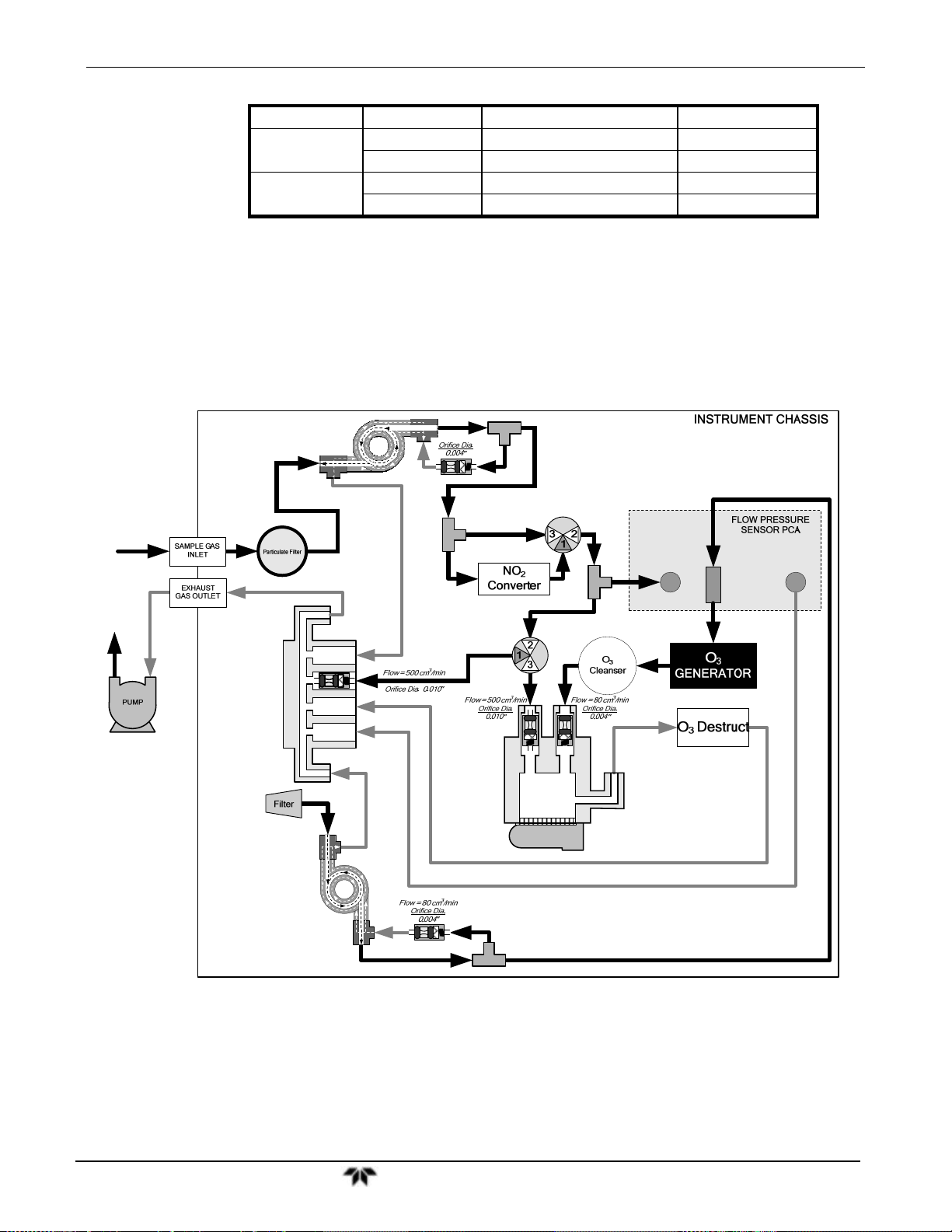
Model 9110T NOx Analyzer Getting Started
Zero/Span Open to ZERO AIR inlet 3 2
ZERO CAL
SPAN CAL
Sample/Cal Open to ZERO/SPAN Valve 1 2
Zero/Span Open to ZERO AIR inlet 3 2
Sample/Cal Open to ZERO/SPAN Valve 1 2
Zero/Span Open to SPAN inlet 1 2
3.3.2.6. Gas Conditioner Options
AMMONIA REMOVAL SAMPLE CONDITIONER (OPT 86A)
The 9110T includes a Nafion® permeation gas exchange tube to remove H2O a from the ozone generator
supply gas stream to a dew point of about -20° C (~600 ppm H
of ammonia (NH
) up to about 1 ppm.
3
An additional Sample Conditioner can be added to the 9110T’s sample gas stream.
Sample Gas
Dryer/Scrubber
NH
3
O) and effectively remove concentrations
2
NO/NO
X
VALVE
SAMPLE
PRESSURE
SENSOR
AUTOZERO
VALVE
EXHAUST MANIFOLD
PMT
DRYER
PERMAPURE
Figure 3-28: Pneumatics for Sample Conditioner OPT 86A
FLOW
O
3
SENSOR
VACUUM
PRESSURE
SENSOR
ZERO AIR SCRUBBER (OPT 86C), FOR Z/S VALVES
Teledyne Analytical Instruments 72
Page 73

Model 9110TH NOx Analyzer Getting Started
An external zero air scrubber for Z/S valves can be used in place of a zero air generator The following
pneumatic diagram illustrates the internal and external flow for a 9110T analyzer with a Z/S valve option
and the Zero Air Scrubber (Option 86C):
Figure 3-29: Pneumatics for External Zero Air Scrubber (OPT 86C) for Z/S Valves
Teledyne Analytical Instruments 73
Page 74

Model 9110T NOx Analyzer Getting Started
3.4. STARTUP, FUNCTIONAL CHECKS, AND INITIAL
CALIBRATION
CAUTION!
If the presence of ozone is detected at any time, power down the instrument
and contact TAI Customer Service as soon as possible:
If you are unfamiliar with the 9110T principles of operation, we recommend that you read Section 13.
For information on navigating the analyzer’s software menus, see the menu trees described in Appendix
A.
3.4.1. START UP
After the electrical and pneumatic connections are made, an initial functional check is in order. Turn on
the instrument. The pump and exhaust fan should start immediately. The display will show a splash
screen and other information during the initialization process while the CPU loads the operating system,
the firmware and the configuration data.
(626) 934-1500 or email: ask_TAI@teledyne.com
The analyzer should automatically switch to Sample Mode after completing the boot-up sequence and
start monitoring the gas. However, there is an approximately one hour warm-up period before reliable
gas measurements can be taken. During the warm-up period, the front panel display may show messages
in the parameters (Param) field.
Teledyne Analytical Instruments 74
Page 75

Model 9110TH NOx Analyzer Getting Started
3.4.2. WARNING MESSAGES
Because internal temperatures and other conditions may be outside the specified limits during the
analyzer’s warm-up period, the software will suppress most warning conditions for 30 minutes after
power up. If warning messages persist after the 30 minutes warm up period is over, investigate their
cause using the troubleshooting guidelines in Section 12.1.
To view and clear warning messages, press:
Table 3-12 lists brief descriptions of the warning messages that may occur during start up.
Teledyne Analytical Instruments 75
Page 76

Model 9110T NOx Analyzer Getting Started
Table 3-12: Possible Warning Messages at Start-Up
MESSAGE MEANING
SYSTEM RESET
1
The computer has rebooted.
ANALOG CAL WARNING
BOX TEMP WARNING
CANNOT DYN SPAN
CANNOT DYN ZERO
2
3
CONFIG INITIALIZED
DATA INITIALIZED
OZONE FLOW WARNING
OZONE GEN OFF 4
RCELL PRESS WARN
RCELL TEMP WARNING
IZS TEMP WARNING 5
CONV TEMP WARNING
PMT TEMP WARNING
AZERO WARN [XXXX]
MV
HVPS WARNING
The A/D or at least one D/A channel have not been calibrated.
The temperature inside the 9110T chassis is outside the specified limits.
Contact closure span calibration failed while DYN_SPAN was set to ON.
Contact closure zero calibration failed while DYN_ZERO was set to ON.
Configuration storage was reset to factory configuration or erased.
DAS data storage was erased before the last power up occurred.
Ozone gas flow is too high or too low for accurate NO
, NO and NO2 readings.
x
Ozone generator is off.
This is the only warning message that automatically clears itself.
It clears itself when the ozone generator is turned on.
Upon power up the Ozone generator will remain off for 30 minutes. This allows the perma-
pure dryer to reach its working dew point.
Reaction cell pressure is too high or too low for accurate NO
Reaction cell temperature is too high or too low for accurate NO
IZS temperature is too high or too low for efficient O
to NO Converter temperature too high or too low to efficiently convert NO2 to NO.
NO
2
production.
3
, NO and NO2 readings.
x
, NO and NO2 readings.
x
PMT temperature outside of warning limits specified by PMT_SET variable.
AutoZero reading too high. The value shown in message indicates auto-zero reading at
time warning was displayed.
High voltage power supply output is too high or too low for proper operation of the PMT.
REAR BOARD NOT DET
RELAY BOARD WARN
SAMPLE FLOW WARN
1
Clears 45 minutes after power up.
2
Clears the next time successful zero calibration is performed.
3
Clears the next time successful span calibration is performed.
4
Clears 30 minutes after power up.
5
Only Appears if the IZS option is installed.
CPU unable to communicate with motherboard..
CPU is unable to communicate with the relay PCA.
The flow rate of the sample gas is outside the specified limits.
Teledyne Analytical Instruments 76
Page 77

Model 9110TH NOx Analyzer Getting Started
3.4.3. FUNCTIONAL CHECKS
After the analyzer’s components have warmed up for at least 60 minutes, verify that the software
properly supports any hardware options that are installed.
For information on navigating through the analyzer’s software menus, see the menu trees described in
Appendix A.1.
Check to ensure that the analyzer is functioning within allowable operating parameters.
Appendix C includes a list of test functions viewable from the analyzer’s front panel as well as their
expected values.
These functions are also useful tools for diagnosing problems with your analyzer.
The enclosed Final Test and Validation Data sheet (P/N 04409) lists these values before the
instrument left the factory.
To view the current values of these parameters press the following button sequence on the analyzer’s
front panel. Remember until the unit has completed its warm up these parameters may not have
stabilized.
3.4.4. INITIAL CALIBRATION
To perform the following calibration you must have sources for zero air and calibration (span) gas
available for input into the inlet/outlet fittings on the back of the analyzer (see Section 3.3.2.1).
Teledyne Analytical Instruments 77
Page 78

Model 9110T NOx Analyzer Getting Started
Note A start-up period of 4-5 hours is recommended prior to performing a
calibration on the analyzer.
The method for performing an initial calibration for the 9110T nitrogen oxides analyzer differs slightly
depending on the whether or not any of the available internal zero air or valve options are installed.
See Section 3.4.4.2 for instructions for initial calibration of the 9110T analyzers in their base
configuration.
See Section 9.3 for instructions for initial calibration of 9110T analyzers possessing an optional
Internal Span Gas Generator (OPT 51A).
See Section 9.4 for information regarding setup and calibration of 9110T analyzers with Z/S Valve
options.
If you are using the 9110T analyzer for EPA monitoring, only the calibration method described in
Section 10 should be used.
3.4.4.1. INTERFERENTS FOR NOX, NO AND NO2 MEASUREMENTS
The chemiluminescence method for detecting NOX is subject to interference from a number of sources
including water vapor (H
9110T has been designed to reject most of these interferences.
Ammonia is the most common interferent, which is converted to NO in the analyzer’s NO2 converter
and creates a NO
If the 9110T is installed in an environment with high ammonia, steps should be taken to
remove the interferent from the sample gas before it enters the reaction cell.
TAI offers a sample gas conditioning option to remove ammonia and water vapor (Section
3.3.2.6).
Carbon dioxide (CO
If the analyzer is used in an application with excess CO
Department (see Section 12.10) for possible solutions.
Excess water vapor can be removed with one of the dryer options described in Section 3.3.2.6. In
ambient air applications, SO
For more detailed information regarding interferents for NOx, NO and NO2 measurement, see Section
13.1.5.
O), ammonia (NH3), sulfur dioxide (SO2) and carbon dioxide (CO2) but the
2
signal artifact.
X
) diminishes the NOX signal when present in high concentrations.
2
, contact TAI's Customer Service
2
interference is usually negligible.
2
3.4.4.2. Initial Calibration Procedure for 9110T Analyzers without Options
The following procedure assumes that:
The instrument DOES NOT have any of the available calibration valve or gas inlet options installed;
Teledyne Analytical Instruments 78
Page 79

Model 9110TH NOx Analyzer Getting Started
Cal gas will be supplied through the SAMPLE gas inlet on the back of the analyzer and;
The pneumatic setup matches that described in Section 3.3.2.
VERIFYING THE REPORTING RANGE SETTINGS
While it is possible to perform the following procedure with any range setting we recommend that you
perform this initial checkout using following reporting range settings:
Unit of Measure: PPB
Reporting Range: 500 ppb
Mode Setting: SNGL
While these are the default setting for the 9110T analyzer, it is recommended that you verify them before
proceeding with the calibration procedure, by pressing the following menu button sequence:
Teledyne Analytical Instruments 79
Page 80

Model 9110T NOx Analyzer Getting Started
VERIFYING THE EXPECTED NO
IMPORTANT
AND NO SPAN GAS CONCENTRATION
X
IMPACT ON READINGS OR DATA
Verify the PRECISE Concentration Value of the SPAN gases
independently.
If you supply NO gas to the analyzer, the values for expected NO and
NO
MUST be identical.
x
The NO
and NO span concentration values automatically defaults to 400.0 PPB and it is recommended
x
that calibration gases of that concentration be used for the initial calibration of the unit.
Teledyne Analytical Instruments 80
Page 81

Model 9110TH NOx Analyzer Getting Started
To verify that the analyzer span setting is set for 400 PPB, press:
Teledyne Analytical Instruments 81
Page 82

Model 9110T NOx Analyzer Getting Started
INITIAL ZERO/SPAN CALIBRATION PROCEDURE
To perform an initial Calibration of the 9110T nitrogen oxides analyzer, press:
The 9110T Analyzer is now ready for operation.
Note
Once you have completed the above set-up procedures, please fill out
the Quality Questionnaire that was shipped with your unit and return it
to Teledyne. This information is vital to our efforts in continuously
improving our service and our products. THANK YOU.
Teledyne Analytical Instruments 82
Page 83

Model 9110TH NOx Analyzer Getting Started
This page intentionally left blank.
Teledyne Analytical Instruments 83
Page 84

Page 85

Model 9110TH NOx Analyzer Part II
PART II
–
OPERATING INSTRUCTIONS
Teledyne Analytical Instruments 85
Page 86

Model 9110T NOx Analyzer Part II
This page intentionally left blank.
Teledyne Analytical Instruments 86
Page 87

Model 9110TH NOx Analyzer Overview of Operating Modes
4. OVERVIEW OF OPERATING MODES
To assist in navigating the analyzer’s software, a series of menu trees is available for reference in
Appendix A of this manual.
Note Some control buttons on the touch screen do not appear if they are not
applicable to the menu that you’re in, the task that you are performing, the
command you are attempting to send, or to incorrect settings input by the
user. For example, the ENTR button may disappear if you input a setting
that is invalid or out of the allowable range for that parameter, such as
trying to set the 24-hour clock to 25:00:00. Once you adjust the setting to
an allowable value, the ENTR button will re-appear.
The 9110T analyzer software has a variety of operating modes. The most common mode that the
analyzer will be operating in is the SAMPLE mode. In this mode, a continuous read-out of the NO
concentrations can be viewed on the front panel and output as an analog voltage from rear panel
terminals.
x
The second most important operating mode is SETUP mode. This mode is used for
configuring the various sub systems of the analyzer such as for the DAS system, the reporting ranges,
or the serial (RS-232 / RS-485 / Ethernet) communication channels. The SETUP mode is also used for
performing various diagnostic tests during troubleshooting.
Figure 4-1: Front Panel Display
The mode field of the front panel display indicates to the user which operating mode the unit is currently
running.
In addition to SAMPLE and SETUP, other modes the analyzer can be operated in are described in Table
7-1 below.
Teledyne Analytical Instruments 87
Page 88

Model 9110T NOx Analyzer Overview of Operating Modes
Table 4-1: Analyzer Operating Modes
MODE EXPLANATION
DIAG
LO CAL A Unit is performing LOW SPAN (midpoint) calibration initiated automatically by the analyzer’s
LO CAL R Unit is performing LOW SPAN (midpoint) calibration initiated remotely through the COM ports or
M-P CAL
SAMPLE
SAMPLE A
SETUP X.#2 SETUP mode is being used to configure the analyzer. The gas measurement will continue during
SPAN CAL A1
SPAN CAL M1
SPAN CAL R1 Unit is performing SPAN calibration initiated remotely through the COM ports or digital control
ZERO CAL A1
ZERO CAL M
ZERO CAL R1 Unit is performing ZERO calibration procedure initiated remotely through the COM ports or digital
1
Only Appears on units with Z/S valve or IZS options.
2
The revision of the analyzer firmware is displayed following the word SETUP, e.g., SETUP G.3.
1
One of the analyzer’s diagnostic modes is active.
AUTOCAL feature
digital control inputs.
This is the basic calibration mode of the instrument and is activated by pressing the CAL button.
Sampling normally, flashing text indicates adaptive filter is on.
Indicates that unit is in SAMPLE mode and AUTOCAL feature is activated.
setup.
Unit is performing SPAN calibration initiated automatically by the analyzer’s AUTOCAL feature
Unit is performing SPAN calibration initiated manually by the user.
inputs.
Unit is performing ZERO calibration procedure initiated automatically by the AUTOCAL feature
Unit is performing ZERO calibration procedure initiated manually by the user.
control inputs.
4.1. SAMPLE MODE
This is the analyzer’s standard operating mode. In this mode, the instrument is a calculating
NO
, NO and NO
x
panel display. While the instrument is in SAMPLE mode, this field provides a readout of all the gas
concentrations being measured by the 9110T: NO
When the analyzer is in sample mode the PARAM field will display warning messages and test
functions that give the user information about the operational status of the analyzer.
4.1.1. TEST FUNCTIONS
A variety of TEST functions are available for viewing at the front panel whenever the analyzer is at the
MAIN MENU. These functions provide information about the various functional parameters related to
the analyzer’s operation and its measurement of gas concentrations. This information is particularly
when troubleshooting a performance problem with the 9110T (see Section 13). Figure 4-2 will display
the Test Functions on the front panel screen. Table 4-2 lists the available TEST functions.
DISPLAY PARAMETER UNITS DESCRIPTION
RANGE
concentrations. These values are displayed in the CONC field of the analyzer's front
2
, NO and NO2.
x
Table 4-2: Test Functions Defined
The Full Scale limit at which the reporting range of the analyzer’s ANALOG
OUTPUTS is currently set.
THIS IS NOT the Physical Range of the instrument. See Section
more information.
RANGE
PPB,
PPM,
UGM
&
5.4.1 for
Teledyne Analytical Instruments 88
Page 89

Model 9110TH NOx Analyzer Overview of Operating Modes
1
DISPLAY PARAMETER UNITS DESCRIPTION
MGM
RANGE1
RANGE2
RANGE1
RANGE2
RANGE3
NOX STB
SAMP FLW
OZONE FL
PMT
NORM PMT
AZERO
HVPS
RCELL TEMP
BOX TEMP
PMT TEMP
IZS TEMP
1
MOLY TEMP
RCEL
SAMP
NOX SLOPE
NOX OFFS
NO SLOPE
NO OFFS
TEST
TIME
Only appears if Internal Span Gas Generator option is installed.
STABILITY PPB
SAMPFLOW CC/M
OZONEFLOW CC/M
PMT MV
NORMPMT MV
AUTOZERO MV
HVPS V
RCELLTEMP C
BOXTEMP C
PMTTEMP C
IZSTEMP C
CONVTEMP C
RCELLPRESS IN-HG-A
SAMPPRESS
IN-HG-A
NOXSLOPE
NOXOFFSET MV
NOSLOPE
NOOFFSET MV
TESTCHAN MV
CLOCKTIME HH:MM:SS
If AUTO Range mode has been selected, two RANGE functions will
appear, one for each range:
RANGE1: The range setting for all analog outputs.
RANGE2: The HIGH range setting for all analog outputs.
If the IND Range mode has been selected, three RANGE functions will
appear, one for each range:
RANGE1:
RANGE2: NO concentration output un A2.
RANGE2:
The standard deviation of concentration readings of the selected gas.
Data points are recorded every ten seconds. The calculation uses the
last 25 data points.
Gas flow rate of the sample gas into the reaction cell.
Gas flow rate of O3 gas into the reaction cell.
The raw signal output of the PMT.
The signal output of the PMT after is has been normalized for temperature,
pressure, auto-zero offset, but not range.
The PMT signal with zero NOX, which is usually slightly different from 0 V.
This offset is subtracted from the PMT signal and adjusts for variations in
the zero signal.
The output power level of the high voltage power supply.
The temperature of the gas inside the reaction cell temperature.
The temperature inside the analyzer chassis.
The temperature of the PMT .
The temperature of the internal span gas generator's permeation tube.
The temperature of the analyzer's NO
The current pressure of the sample gas in the reaction cell as measured at
the vacuum manifold.
The current pressure of the sample gas as it enters the reaction cell,
measured between the NO/NO
The slope calculated during the most recent NOx zero/span calibration.
The offset calculated during the most recent NOx zero/span calibration.
The slope calculated during the most recent NO zero/span calibration.
The offset calculated during the most recent NO zero/span calibration.
Displays the signal level of the Test Function that is currently being
produced by the Analog Output Channel A4.
The current time. This is used to create a time stamp on DAS readings,
and by the AutoCal feature to trigger calibration events.
NO
concentration output un A1.
x
NO2 concentration output un A3.
NO converter.
2
and Auto-Zero valves.
x
To view these TEST functions, press,
Teledyne Analytical Instruments 89
Page 90

Model 9110T NOx Analyzer Overview of Operating Modes
IMPORTANT
Figure 4-2: Viewing 9110T Test Functions
IMPACT ON READINGS OR DATA
A value of “XXXX” displayed for any of the TEST functions indicates an
out-of-range reading or the analyzer’s inability to calculate it. All
pressure measurements are represented in terms of absolute pressure.
Absolute, atmospheric pressure is 29.92 in-Hg-A at sea level. It
decreases about 1 in-Hg per 300 m gain in altitude. A variety of factors
such as air conditioning and passing storms can cause changes in the
absolute atmospheric pressure.
Teledyne Analytical Instruments 90
Page 91

Model 9110TH NOx Analyzer Overview of Operating Modes
4.1.2. WARNING MESSAGES
The most common and serious instrument failures will activate Warning Messages that are displayed on
the analyzer’s Front Panel. They are listed on Table 4-3 as follows:
Table 4-3: Warning Messages Defined
MESSAGE MEANING
ANALOG CAL WARNING The A/D or at least one D/A channel has not been calibrated.
AZERO WARN
BOX TEMP WARNING The temperature inside the 9110T chassis is outside the specified limits.
CANNOT DYN SPAN
CANNOT DYN ZERO Contact closure zero calibration failed while DYN_ZERO was set to ON.
CONFIG INITIALIZED Configuration storage was reset to factory configuration or erased.
CONV TEMP WARNING
DATA INITIALIZED DAS data storage was erased before the last power up occurred.
HVPS WARNING
IZS TEMP WARNING 1
OZONE FLOW WARNING
OZONE GEN OFF
PMT TEMP WARNING
RCELL PRESS WARN
RCELL TEMP WARNING
REAR BOARD NOT DET Motherboard was not detected during power up.
RELAY BOARD WARN
SAMPLE FLOW WARN The flow rate of the sample gas is outside the specified limits.
SYSTEM RESET The computer has rebooted.
Auto-zero reading above limit specified by AZERO_LIMIT variable. Value shown
in message indicates auto-zero reading at time warning was displayed.
Contact closure span calibration failed while DYN_SPAN was set to ON.
NO
NO converter temperature outside of warning limits specified by
2
CONV_SET variable.
High voltage power supply output outside of warning limits specified by
HVPS_SET variable.
IZS temperature outside of warning limits specified by IZS_SET variable.
Ozone flow outside of warning limits specified by OFLOW_SET variable.
Ozone generator is off. This warning message clears itself when the ozone
generator is turned on.
PMT temperature outside of warning limits specified by PMT_SET variable.
Reaction cell pressure outside of warning limits specified by
RCELL_PRESS_SET variable.
Reaction cell temperature outside of warning limits specified by RCELL_SET
variable.
CPU is unable to communicate with the relay PCA.
1
Only Appears if the Internal Span Gas Generator option is installed.
Teledyne Analytical Instruments 91
Page 92

Model 9110T NOx Analyzer Overview of Operating Modes
4.2. CALIBRATION MODE
Pressing the CAL button, switches the analyzer into calibration mode. In this mode the user can, in
conjunction with introducing zero or span gases of known concentrations into the analyzer, cause it to
adjust and recalculate the slope (gain) and offset of the its measurement range. This mode is also used to
check the current calibration status of the instrument.
If the instrument includes one of the available zero/span valve options, the SAMPLE mode display will
also include CALZ and CALS buttons. Pressing either of these buttons also puts the instrument into
calibration mode.
The CALZ button is used to initiate a calibration of the analyzer’s zero point using internally
generated zero air.
The CALS button is used to calibrate the span point of the analyzer’s current reporting range using
span gas.
Note It is recommended that this span calibration be performed at 80% of full
scale of the analyzer’s currently selected reporting range.
EXAMPLES:
If the reporting range is set for 0 to 500 ppb, an appropriate span point
would be 400 ppb.
If the of the reporting range is set for 0 to 1000 ppb, an appropriate span
point would be 800 ppb.
Due to the critical importance and complexity, calibration operations are described in detail in other
sections of the manual:
Section 9 details setting up and performing standard calibration operations or checks.
Section 10 details setting up and performing EPA protocol calibrations.
For information on using the automatic calibrations feature (ACAL) in conjunction with the one of the
calibration valve options, see Sections 9.4.3 and 9.5.
IMPORTANT
To avoid inadvertent adjustments to critical settings, activate calibration
security by enabling password protection in the SETUP – PASS menu
(Section 5.5).
4.3. SETUP MODE
The SETUP Mode contains a variety of choices that are used to configure the analyzer’s hardware and
software features, perform diagnostic procedures, gather information on the instruments performance and
configure or access data from the internal data acquisition system (DAS). For a visual representation of
the software menu trees, refer to Appendix A.
IMPACT ON READINGS OR DATA
SETUP Mode is divided between Primary and Secondary Setup menus and can be protected through
password security.
Teledyne Analytical Instruments 92
Page 93

Model 9110TH NOx Analyzer Overview of Operating Modes
4.3.1. PASSWORD SECURITY
SETUP Mode can be protected by password security through the SETUP>PASS menu (Section 5.5) to
prevent unauthorized or inadvertent configuration adjustments.
4.3.2. PRIMARY SETUP MENU
The areas accessed and configured under the primary SETUP Mode menu are shown in Table 4-4.
Table 4-4: Primary Setup Mode Features and Functions
CONTROL
MODE OR FEATURE
Analyzer Configuration
Auto Cal Feature
Internal Data Acquisition
(DAS)
Analog Output Reporting
Range Configuration
Calibration Password Security
Internal Clock Configuration
Secondary SETUP Mode
(Advanced SETUP features)
BUTTON
LABEL
CFG
ACAL
DAS
RNGE
PASS
CLK
MORE
Lists button hardware and software configuration information. 5.1
Used to set up and operate the AutoCal feature.
Only appears if the analyzer has one of the calibration valve
options installed.
Used to set up the DAS system and view recorded data. 7
Used to configure the output signals generated by the
instruments analog outputs.
Turns the calibration password feature ON/OFF. 5.5
Used to set or adjust the instrument’s internal clock. 5.6
This button accesses the instruments secondary setup menu.
DESCRIPTION
4.3.3. SECONDARY SETUP MENU (SETUP MORE)
The areas accessed and configured under the secondary SETUP Mode menu are shown in Table 4-5.
Table 4-5: Secondary Setup Mode Features and Functions
CONTROL
MODE OR FEATURE
External Communication
Channel Configuration
System Status Variables
System Diagnostic Features
and
Analog Output Configuration
BUTTON
LABEL
COMM
VARS
DIAG
DESCRIPTION
Used to set up and operate the analyzer’s various external I/O
channels including RS-232; RS-485, modem communication
and/or Ethernet access.
Used to view various variables related to the instruments
current operational status.
Changes made to any variable are not acknowledged and
recorded in the instrument’s memory until the ENTR button
is pressed.
Pressing the EXIT button ignores the new setting.
If the EXIT button is pressed before the ENTR button, the
analyzer will beep alerting the user that the newly entered
value has been lost.
Used to access a variety of functions that are used to configure,
test or diagnose problems with a variety of the analyzer’s basic
systems.
Most notably, the menus used to configure the output signals
generated by the instruments’ analog outputs are located here.
MANUAL
SECTION
5.2, 9.5
5.4
See
Table 4-5
MANUAL
SECTION
8
5.8
5.9, 5.9.2
Teledyne Analytical Instruments 93
Page 94

Model 9110T NOx Analyzer Overview of Operating Modes
IMPORTANT
IMPACT ON READINGS OR DATA
Any changes made to a variable during the SETUP procedures are not
acknowledged by the instrument until the ENTR button is pressed. If the
EXIT button is pressed before the ENTR button, the analyzer will make an
audible signal before exiting the menu, alerting the user that the newly
entered value had not been accepted.
Teledyne Analytical Instruments 94
Page 95

Model 9110TH NOx Analyzer Setup Menu
5. SETUP MENU
The SETUP Mode menu is used to set instrument parameters for performing configuration, calibration,
reporting and diagnostics operations according to user needs.
5.1. SETUP CFG: CONFIGURATION INFORMATION
Pressing the CFG button displays the instrument configuration information. This display lists the
analyzer model, serial number, firmware revision, software library revision, CPU type and other
information. Use this information to identify the software and hardware when contacting customer
service. Special instrument or software features or installed options may also be listed here.
5.2. SETUP ACAL: AUTOMATIC CALIBRATION OPTION
The menu button for this option appears only when the instrument has the zero span and/or IZS options.
See Section 9.5 for details.
5.3. SETUP DAS: INTERNAL DATA ACQUISITION SYSTEM
Use the SETUP>DAS menu to capture and record data. Refer to Section 7 for configuration and
operation details.
Teledyne Analytical Instruments 95
Page 96

Model 9110T NOx Analyzer Setup Menu
5.4. SETUP RNGE: ANALOG OUTPUT REPORTING RANGE
CONFIGURATION
Use the SETUP>RNGE menu to configure output reporting ranges, including scaled reporting ranges to
handle data resolution challenges. This section describes configuration for Single, Dual, and Auto Range
modes.
5.4.1. 9110T PHYSICAL RANGES
The 9110T NOx analyzer measures NOx, NO and NO2 concentrations from 2 to 20,000 ppb.
Electronically the 9110T analyzer converts the 0-5 volt analog signal output by the PMT into a digital
signal with 4096 counts of resolution. Since its measurement range is 0 ppb to 20,000 ppb, this only
allows about 3 ppb per count. While this might be acceptable for high concentration measurements
made in parts per million units (ppm), it is not good enough for lower level NO
overcome this limitation the 9110T is designed with two physical measurement ranges:
A LOW range that measures concentration from 0 ppb to 2,000 ppb with a resolution of 0.27 ppb per
count.
A HIGH range that measures the full 20,000 ppb range of the analyzer.
measurements. To
x
The analyzer’s CPU chooses the appropriate range based on how the user sets up the reporting ranges for
the instruments analog outputs when an analog range is selected with a lower limit between 0 and 2000
ppb the analyzer will utilize its low physical range. When an analog range is in use that has a reporting
range with an upper limit set between 2001 and 20,000 ppb the instrument will operate in its high
physical range.
Once both ranges have been using the same span gas values the analyzer’s front panel will accurately
report concentrations between 0 and 20,000 ppb, seamlessly switching between the low and high
physical ranges regardless of the selected analog reporting range.
5.4.2. 9110T ANALOG OUTPUT REPORTING RANGES
For applications using chart recorders or other analog recording devices, the 9110T's 20,000 ppb
physical range can cause resolution problems. For example, in an application where the expected
concentrations of NO, NO
only 2.5% of the instrument’s 20,000 ppb physical range. The corresponding output signal would then
only be recorded across 2.5% of the range of the recording device.
The 9110T solves this problem by allowing the user to select a reporting range for the analog outputs
that only includes that portion of the physical range that covers the specific application. This increases
the reliability and accuracy of the analyzer by avoiding additional gain-amplification circuitry.
Note Only the reporting range of the analog outputs is scaled.
and NOx are typically less than 500 ppb, the full scale of expected values is
2
Both the DAS values stored in the CPU’s memory and the concentration
values reported on the front panel are unaffected by the settings chosen
for the reporting range(s) of the instrument.
Teledyne Analytical Instruments 96
Page 97

Model 9110TH NOx Analyzer Setup Menu
5.4.2.1. Analog Output Ranges for NOx, NO and NO2 Concentration
The analyzer has three active analog output signals related to NOx, NO and NO2 concentration,
accessible through a connector on the rear panel.
ANALOG OUT
NO Concentration NOx Concentration
A1 A2 A3 A4
+ - + - + - + -
Figure 5-1: Analog Output Connector Pin Out
The A1, A2 and A3 channels output a signal that is proportional to the NO
of the sample gas, respectively. The 9110T can be set so that these outputs operate in one of the three
following modes: single range mode, independent range mode, or automatic range mode (Section 5.4.3).
Additionally, the signal levels of outputs A1, A2 and A3 outputs can be:
Configured full scale outputs of: 0 - 0.1 VDC; 0 – 1 VDC; 0 – 5 VDC or; 0 – 10 VDC.
NO2 Concentration
Test Channel
or O
concentration
2
(if optional O2 sensor
is installed)
, NO and NO2 concentrations
x
Equipped with optional 0-20 mADC current loop drivers (see Section 3.3.1.4 ) and configured for any
current output within that range analog output (e.g. 0-20 mA, 2-20 mA, 4-20 mA, etc.).
Together these two set of parameters allow the user a great deal of flexibility in how the instrument
reports NOx , NO and NO2 concentration to external devices. For example, Using the IND mode the
following configuration could be created:
A1 OUTPUT: NO
Output Signal = 4 – 20 mA representing 0-1000 ppb concentration values
x
A2 OUTPUT: NO Output Signal = 0 – 10 VDC representing 0-500 ppb concentration values.
A3 OUTPUT: NO
Output Signal = 0 – 5 VDC representing 0-500 ppb concentration values.
2
The user may also add a signal offset independently to each output (see Section 5.9.3.9) to match the
electronic input requirements of the recorder or data logger to which the output is connected.
IMPORTANT
IMPACT ON READINGS OR DATA
The instrument does not remember upper range limits settings associated
with the individual modes. Changes made to the range limits (e.g. 400 ppb
600 ppb) when in one particular mode will alter the range limit settings
for the other modes.
When switching between reporting range modes, ALWAYS check and
Teledyne Analytical Instruments 97
Page 98

Model 9110T NOx Analyzer Setup Menu
reset the upper range limits for the new mode selection..
5.4.2.2. Analog Output Reporting Range Default Settings
The default setting for these the reporting ranges of the analog output channels A1, A2 and A3 are:
SNGL mode
0 to 500.0 ppb
0 to 5 VDC
5.4.3. SETUP RNGE MODE
Single range mode (SNGL) reports all three of the NOx gas concentrations using the same reporting
range span (see Section 5.4.3.1).
Independent range mode (IND) allows the NOx, NO and NO2 analog outputs to be set with different
reporting range spans (see Section 5.4.3.2).
Automatic range mode (AUTO) allows the analyzer to automatically switch the reporting range between
two user upper span limits (designated LOW and HIGH) based on the actual concentrations being
measured for each (see Section 5.4.3.3). These are not the same as the analyzer’s low and high physical
ranges.
5.4.3.1. SETUP RNGE MODE SNGL: Configuring the 9110T Analyzer for Single
Range Mode
Note
When the single range mode is selected (SNGL), all analog NO
(A1, A2 and A3) are slaved together and set to the same reporting range limits (e.g. 500.0 ppb). This
reporting range can be set to any value between 100 ppb and 20,000 ppb.
Although all three NO
of the analog outputs may still be configured for different values (e.g. 0-5 VDC, 0-10 VDC, etc; see
Section 5.9.3.1).
To select SNGL range mode and to set the upper limit of the range, press:
Single Range is the default reporting range mode for the analyzer.
, NO and NO2 concentration outputs
x
outputs share the same concentration reporting range, the electronic signal ranges
x
Teledyne Analytical Instruments 98
Page 99

Model 9110TH NOx Analyzer Setup Menu
5.4.3.2. SETUP RNGE MODE IND: Configuring the 9110T Analyzer for
Independent Range Mode
The independent range mode (IND) assigns the three NO
analog output channels. In IND range mode the RANGE test function displayed on the front panel will
then be replaced by three separate functions:
Table 5-1: IND Mode Analog Output Assignments
TEST
FUNCTION
RANGE1
RANGE2
RANGE3
CONCENTRATION
REPORTED
A1
NO
x
NO A2
A3
NO
2
Each can be configured with a different reporting range upper limit and analog signal span:
, NO and NO2 concentrations to individual
x
ANALOG OUTPUT
CHANNEL
Teledyne Analytical Instruments 99
Page 100
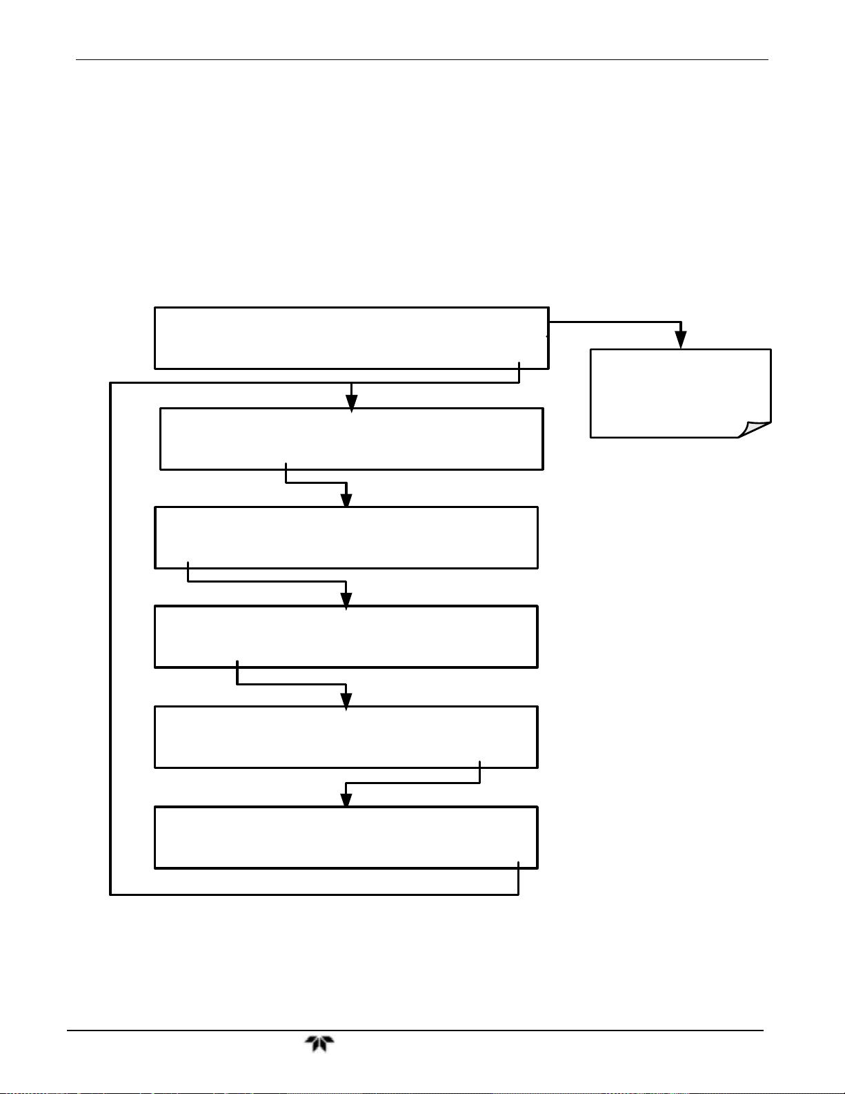
Model 9110T NOx Analyzer Setup Menu
EXAMPLE:
NOx Concentration – RANGE1 Set for 0-800 ppb & output A1 set for 0-10 VDC
NO
NO
Concentration – RANGE2 Set for 0-200 ppb & output A2 set for 0-5 VDC
Concentration – RANGE3 Set for 0-400 ppb & output A3 set for 0-5 VDC
2
Setting analog range limits to different values does not affect the instrument’s calibration.
To select the IND range mode, press the following buttons:
SAMPLE RANGE=500.0 PPM NOX= XXXX
<TST TST> CAL SETUP
Concentration field
displays all gases.
SETUP X.X PRIMARY SETUP MENU
CFG DAS RNGE PASS CLK MORE EXIT
SETUP X.X RANGE MODE MENU
MODE SET UNIT DIL EXIT
SETUP X.X RANGE MODE:SNGL
SNGL IND AUTO ENTR EXIT
SETUP X.X RANGE MODE:IND
SNGL IND AUTO ENTR EXIT
SETUP X.X RANGE MODE MENU
MODE SET UNIT DIL EXIT
Teledyne Analytical Instruments 100
 Loading...