

Page 1

INSTRUCTION MANUAL
MODEL 9110EH
NITROGEN OXIDES ANALYZER
NITROGEN OXIDES ANALYZER
© Teledyne Instruments
Analyical Instruments
(TAI)
16830 Chestnut Street
City of Industry, California, CA 91748-1020,USA
USA
Toll-free Phone: 1.888.789.8168
Phone: 1.626.961.9221 or 1.626.934.1500
Fax: 1.626.961.2538 or 1.626.934.1651
Email: ask_tai@teledyne.com
Website: http://www.teledyne-ai.com
M9110EH
Rev. 0
Copyright 2003 TAI 24-September, 2003
Page 2
Documentation Model 9110EH Instruction Manual
SAFETY MESSAGES
Your safety and the safety of others is very important. We have provided many important
safety messages in this manual. Please read these messages carefully.
A safety message alerts you to potential hazards that could hurt you or others. Each safety
message is associated with a safety alert symbol. These symbols are found in the manual
and inside the instrument. The definition of these symbols is described below:
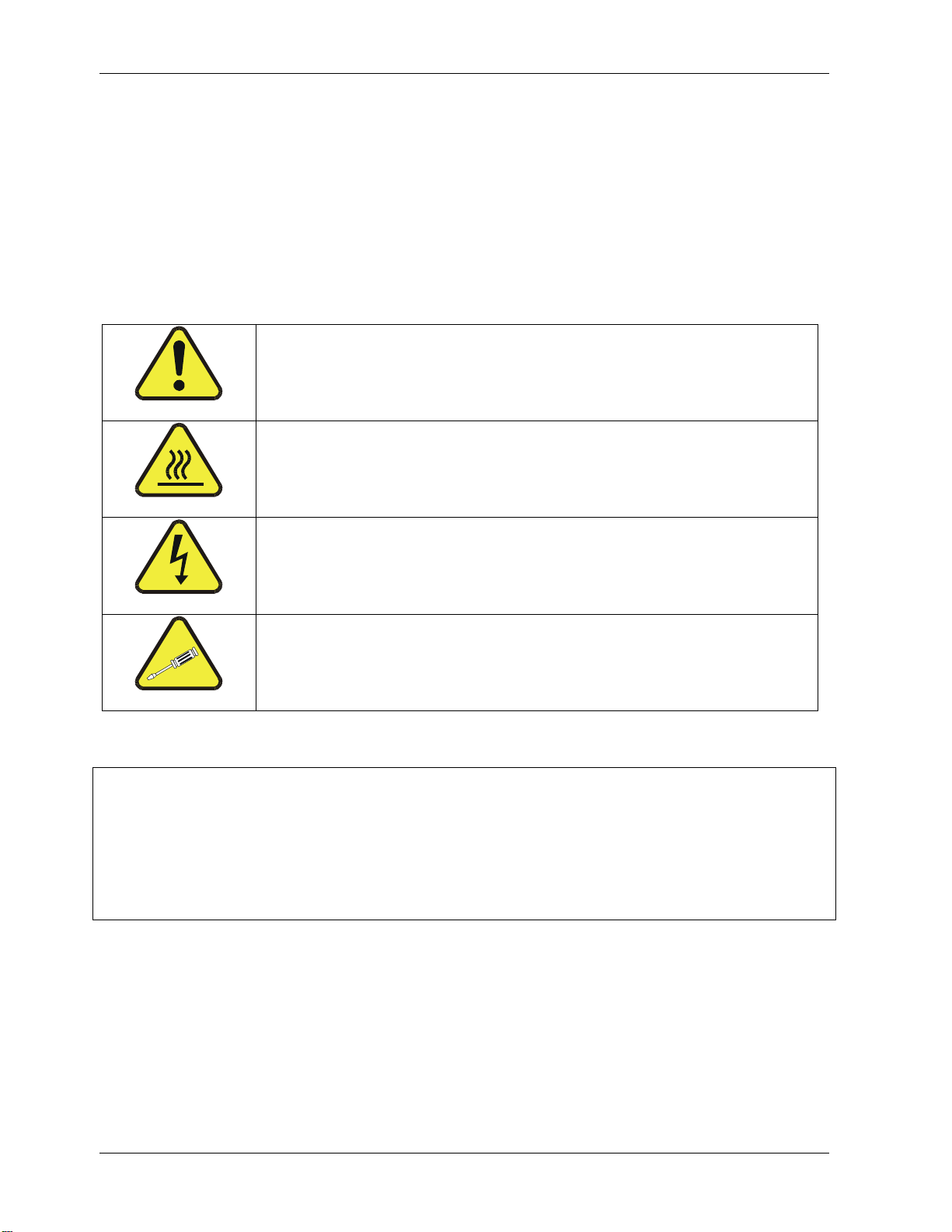
GENERAL SAFETY HAZARD: Refer to the instructions for
details on the specific hazard.
CAUTION: Hot Surface Warning.
CAUTION: Electrical Shock Hazard.
TECHNICIAN SYMBOL: All operations marked with this symbol
are to be performed by qualified maintenance personnel only.
CAUTION
The analyzer should only be used for the purpose and in the manner described in
this manual. If you use the analyzer in a manner other than that for which it was
intended, unpredictable behavior could ensue with possible hazardous
consequences.
This analyzer is for indoor use only and for altitudes up to 2000 m (6500 ft).
ii 9110EH Rev 0
Page 3

Model 9110EH Instruction Manual M9110EH Documentation
TABLE OF CONTENTS
SAFETY MESSAGES ...............................................................................................................II
TABLE OF CONTENTS .......................................................................................................... III
LIST OF FIGURES.................................................................................................................IX
LIST OF TABLES................................................................................................................... XI
LIST OF APPENDICES ....................................................................................................... XIII
1. M9110EH DOCUMENTATION...............................................................................................1
1.1. Available Documentation ...............................................................................................1
1.2. Manual Structure..........................................................................................................1
1.3. How to use this Instruction Manual .................................................................................3
2. SPECIFICATIONS, APPROVALS AND WARRANTY ...............................................................5
2.1. M9110EH Operating Specifications..................................................................................5
2.2. EPA Equivalency Designation..........................................................................................6
2.3. CE Mark Compliance ..................................................................................................... 7
2.4. Warranty.....................................................................................................................7
3. GETTING STARTED.............................................................................................................9
3.1. Unpacking and Initial Setup ........................................................................................... 9
3.2. M911EH Layout..........................................................................................................11
3.3. Pneumatic Connections ............................................................................................... 13
3.3.1. Span Gas Defined ................................................................................................ 14
3.3.2. Zero Gas Defined ................................................................................................. 15
3.4. Electrical Connections ................................................................................................. 17
3.4.1. Power Connection ................................................................................................ 17
3.4.2. Analog Output Connections ................................................................................... 17
3.4.3. Ethernet Connection and Configuration.................................................................... 20
3.5. Initial Operation......................................................................................................... 20
3.5.1. Startup............................................................................................................... 20
3.5.2. Warm-Up............................................................................................................ 21
3.5.3. Warning Messages ...............................................................................................22
3.5.4. Functional Check.................................................................................................. 23
3.6. First Calibration..........................................................................................................27
3.6.1. Basic Calibration Procedure ................................................................................... 27
3.6.2. Interferences for NOX Measurements....................................................................... 30
4. FREQUENTLY ASKED QUESTIONS & GLOSSARY................................................................31
4.1. Frequently Asked Questions......................................................................................... 31
4.2. Glossary ...................................................................................................................32
5. OPTIONAL HARDWARE AND SOFTWARE ..........................................................................35
5.1. External Pumps (Option 10)......................................................................................... 35
5.2. Rack Mount Kits (Options 20-23) .................................................................................. 35
5.3. Carrying Strap Handle (Option 29)................................................................................ 35
5.4. Current Loop Analog Outputs (Option 41) ...................................................................... 36
5.5. Particulate Filter Kit (Option 42A) ................................................................................. 37
5.6. Calibration Valve Options............................................................................................. 37
5.6.1. Zero/Span Valves (Option 50)................................................................................ 37
5.6.2. Internal Zero/Span (IZS) (Option 51) ..................................................................... 38
5.6.3. IZS Permeation Tubes (Options 53 & 55)................................................................. 39
5.7. Scrubbers and Expendables ......................................................................................... 40
5.7.1. Charcoal Scrubber (Option 64A)............................................................................. 40
5.7.2. Charcoal Refill Kit (Part# 00596)............................................................................ 40
5.7.3. Zero Air Scrubber (Option 64B).............................................................................. 40
5.7.4. Zero Air Scrubber Maintenance Kit (Option 43)......................................................... 40
5.7.5. M9110EH Expendables Kit (Option 42)....................................................................41
5.7.6. M9110EH Spare Parts Kit (Option 43) .....................................................................41
5.8. Communication Options .............................................................................................. 41
5.8.1. RS232 Modem Cables (Options 60 and 60A) ............................................................ 41
5.8.2. RS-232 Multidrop (Option 62) ................................................................................ 41
5.8.3. Ethernet (Option 63) ............................................................................................ 41
5.9. Sample Gas Conditioners (Options 86 & 88) ................................................................... 42
M9110EH Rev 0 iii
Page 4

Model 9110EH Instruction Manual M9110EH Documentation
5.10. Additional Manual (Option 70).....................................................................................43
5.11. Manual on CD (Option 70A) ........................................................................................43
5.12. Extended Warranty (Options 92 & 93)..........................................................................43
6. OPERATING INSTRUCTIONS ........................................................................................... 44
6.1. Overview of Operating Modes .......................................................................................45
6.2. Sample Mode .............................................................................................................46
6.2.1. Test Functions .....................................................................................................46
6.2.2. Warning Messages................................................................................................48
6.2.3. Calibration Functions ............................................................................................48
6.3. Calibration Mode.........................................................................................................49
6.4. Setup Mode ...............................................................................................................49
6.4.1. Password (PASS)..................................................................................................49
6.4.2. Configuration Information (CFG).............................................................................51
6.4.3. Clock (CLK) .........................................................................................................51
6.5. Setup - Range Configuration (RNGE) ............................................................................. 52
6.5.1. Physical and Analog Output Ranges.........................................................................53
6.5.2. Reporting Range Modes.........................................................................................53
6.5.3. Single Range mode (SNGL)....................................................................................54
6.5.4. Independent Range Mode (IND) .............................................................................54
6.5.5. Auto Range Mode (AUTO) ......................................................................................56
6.5.6. Range Units.........................................................................................................56
6.5.7. Dilution Ratio.......................................................................................................57
6.6. Setup - Internal Variables (VARS) .................................................................................59
6.7. Setup - Diagnostics (DIAG) ..........................................................................................61
6.7.1. Signal I/O ...........................................................................................................62
6.7.2. Analog Output Step Test........................................................................................63
6.7.3. Analog I/O Configuration ....................................................................................... 64
6.7.3.1. Analog Output Signal Type and Range Selection .................................................65
6.7.3.2. Analog Output Calibration Mode .......................................................................66
6.7.3.3. Manual Analog Output Calibration.....................................................................68
6.7.3.4. Analog Output Offset Adjustment .....................................................................69
6.7.3.5. Current Loop Output Adjustment......................................................................70
6.7.3.6. AIN Calibration ..............................................................................................72
6.7.4. Test Channel Output .............................................................................................72
6.7.5. Optic Test ...........................................................................................................74
6.7.6. Electrical Test ......................................................................................................74
6.7.7. Ozone Generator Override .....................................................................................75
6.7.8. Flow Calibration ...................................................................................................76
6.8. Digital Inputs and Outputs ...........................................................................................76
6.8.1. Status Outputs.....................................................................................................76
6.8.2. Control Inputs......................................................................................................77
6.9. Setup - Communication Ports (COMM) ...........................................................................78
6.9.1. Analyzer ID .........................................................................................................79
6.9.2. COM Port Default Settings .....................................................................................79
6.9.3. COM Port Cable Connections ..................................................................................80
6.9.4. COM2 Configuration..............................................................................................80
6.9.5. DTE and DCE Communication.................................................................................81
6.9.6. COM Port Communication Modes ............................................................................81
6.9.7. COM Port Baud Rate .............................................................................................84
6.9.8. COM Port Testing .................................................................................................84
6.9.9. Ethernet Port Configuration....................................................................................85
6.9.10. Hessen Mode Configuration ..................................................................................88
6.10. Setup - Data Acquisition System (DAS) ........................................................................89
6.10.1. iDAS Structure ...................................................................................................90
6.10.1.1. iDAS Channels ............................................................................................. 90
6.10.1.2. iDAS Parameters..........................................................................................91
6.10.1.3. iDAS Triggering Events..................................................................................92
6.10.2. Configuring the iDAS...........................................................................................92
6.10.2.1. Default M200E iDAS Configuration ..................................................................92
6.10.2.2. Viewing iDAS Data and Settings .....................................................................94
iv M9110EH Rev 0
Page 5

Model 9110EH Instruction Manual M9110EH Documentation
6.10.2.3. Editing iDAS Data Channels ........................................................................... 95
6.10.2.4. Trigger Events............................................................................................. 97
6.10.2.5. Editing iDAS Parameters ............................................................................... 98
6.10.2.6. Sample Period and Report Period ................................................................. 100
6.10.2.7. Number of Records .................................................................................... 101
6.10.2.8. RS-232 Report Function .............................................................................. 102
6.10.2.9. Compact Report......................................................................................... 103
6.10.2.10. Starting Date........................................................................................... 103
6.10.2.11. Disabling/Enabling Data Channels............................................................... 103
6.10.2.12. HOLDOFF Feature..................................................................................... 104
6.10.3. Remote iDAS Configuration................................................................................ 105
6.11. Remote Operation of the Analyzer............................................................................. 106
6.11.1. Basic Operation................................................................................................ 106
6.11.1.1. Terminal Operating Modes........................................................................... 106
6.11.1.2. Help Commands in Terminal Mode................................................................ 107
6.11.1.3. Command Syntax ...................................................................................... 107
6.11.1.4. Data Types ............................................................................................... 108
6.11.2. Status Reporting .............................................................................................. 108
6.11.3. Remote Access by Modem ................................................................................. 109
6.11.4. COM Port Password Security .............................................................................. 110
6.11.5. APICOM Remote Control Program ....................................................................... 111
6.11.6. Additional Communications Documentation .......................................................... 112
7. CALIBRATION PROCEDURES ..........................................................................................113
7.1. Calibration Preparations ............................................................................................ 113
7.1.1. Required Equipment, Supplies, and Expendables .................................................... 113
7.1.2. Zero Air............................................................................................................ 113
7.1.3. Span Gas Standards ........................................................................................... 113
7.1.4. NO2 Permeation Tubes........................................................................................ 114
7.1.5. Calibration Gas Traceability ................................................................................. 114
7.1.6. Data Recording Devices ...................................................................................... 114
7.1.7. NO2 Conversion Efficiency ................................................................................... 114
7.2. Manual Calibration.................................................................................................... 116
7.2.1. Connect Zero Air and Span Gases to the Analyzer................................................... 117
7.2.2. Set Expected NO and NOX Span Gas Concentrations................................................ 117
7.2.3. Perform Zero/Span Calibration:............................................................................ 118
7.3. Calibration Checks.................................................................................................... 119
7.4. Calibration with Zero/Span Valves .............................................................................. 119
7.5. Calibration with IZS Option........................................................................................ 120
7.6. Calibration Checks with IZS or Zero/Span Valves .......................................................... 123
7.7. Calibration With Independent or AUTO Ranges.............................................................. 124
7.7.1. Calibration in AUTO Range Mode .......................................................................... 124
7.7.2. Independent Range Mode.................................................................................... 125
7.7.3. Calibration With Remote Contact Closures ............................................................. 125
7.8. Automatic Calibration (AutoCal).................................................................................. 126
7.9. Calibration Quality Analysis........................................................................................ 128
8. EPA PROTOCOL CALIBRATION .......................................................................................131
8.1. Calibration of Equipment ........................................................................................... 131
8.2. Gas Phase Titration (GPT).......................................................................................... 133
8.2.1. GPT Principle of Operation ................................................................................... 133
8.2.2. GPT Calibrator Check Procedure ........................................................................... 133
8.2.3. Example GPT Calculation..................................................................................... 134
8.3. Multipoint Calibration Procedure ................................................................................. 136
8.3.1. Zero Calibration................................................................................................. 137
8.3.2. Span Calibration ................................................................................................ 137
8.3.3. GPT NO2 Calibration ........................................................................................... 138
8.4. Calibration Frequency ............................................................................................... 139
8.5. Other Quality Assurance Procedures............................................................................ 139
8.6. Summary of Quality Assurance Checks ........................................................................ 140
8.7. Short Calibration Checks ........................................................................................... 141
8.7.1. Zero/Span Check Procedures ............................................................................... 141
M9110EH Rev 0 v
Page 6

Model 9110EH Instruction Manual M9110EH Documentation
8.7.2. Precision Check.................................................................................................. 142
8.7.3. Precision Check Procedure ................................................................................... 142
8.8. Certification of Working Standards .............................................................................. 142
8.8.1. Certification Procedures of Working Standards........................................................ 143
8.8.1.1. Other Methods of Establishing Traceability ....................................................... 143
8.9. References............................................................................................................... 143
9. INSTRUMENT MAINTENANCE ........................................................................................ 145
9.1. Maintenance Schedule............................................................................................... 145
9.2. Predictive Diagnostics................................................................................................ 147
9.3. Maintenance Procedures ............................................................................................ 147
9.3.1. Changing the Sample Particulate Filter ..................................................................148
9.3.2. Changing the O3 Dryer Particulate Filter................................................................. 149
9.3.3. Changing the Ozone Filter Chemical ...................................................................... 150
9.3.4. Rebuilding the External Sample Pump ...................................................................151
9.3.5. Changing the Pump and IZS Dust Filters................................................................ 152
9.3.6. Changing the IZS Permeation Tube....................................................................... 152
9.3.7. Changing the External Zero Air Scrubber ...............................................................153
9.3.8. Changing the NO2 converter................................................................................. 154
9.3.9. Cleaning the Reaction Cell ................................................................................... 155
9.3.10. Cleaning or Changing Critical Flow Orifices ........................................................... 157
9.3.11. Checking for Light Leaks.................................................................................... 158
10. THEORY OF OPERATION .............................................................................................. 159
10.1. Measurement Principle............................................................................................. 159
10.1.1. Chemiluminescence ..........................................................................................159
10.1.2. NOX and NO2 Determination................................................................................ 160
10.1.3. Chemiluminescence Detection ............................................................................ 161
10.1.3.1. The Photo Multiplier Tube ............................................................................ 161
10.1.3.2. Optical Filter.............................................................................................. 162
10.1.4. Auto Zero ........................................................................................................ 162
10.1.5. Measurement Interferences................................................................................ 163
10.1.5.1. Direct Interference ..................................................................................... 163
10.1.5.2. Third Body Quenching................................................................................. 163
10.1.5.3. Light Leaks................................................................................................ 165
10.2. Pneumatic Operation ............................................................................................... 165
10.2.1. Pump and Exhaust Manifold ...............................................................................165
10.2.2. Sample Gas Flow .............................................................................................. 166
10.2.3. Sample Particulate Filter.................................................................................... 167
10.2.4. Ozone Gas Air Flow........................................................................................... 168
10.2.5. O3 Generator ................................................................................................... 168
10.2.6. Perma Pure® Dryer ........................................................................................... 169
10.2.7. Ozone Supply Air Filter...................................................................................... 170
10.2.8. Ozone Scrubber................................................................................................ 171
10.2.9. Flow Rate Control - Critical Flow Orifices .............................................................. 171
10.2.10. Pneumatic Sensors.......................................................................................... 173
10.2.10.1. Vacuum Manifold...................................................................................... 173
10.2.10.2. Sample Pressure Sensor............................................................................ 174
10.2.10.3. Vacuum Pressure Sensor ........................................................................... 174
10.2.10.4. O3 Supply Air Flow Sensor ......................................................................... 174
10.2.11. Dilution Manifold............................................................................................. 175
10.3. Electronic Operation ................................................................................................ 175
10.3.1. CPU ................................................................................................................ 176
10.3.1.1. Disk On Chip ............................................................................................. 177
10.3.1.2. Flash Chip ................................................................................................. 178
10.3.2. Sensor Module, Reaction Cell & PMT .................................................................... 178
10.3.2.1. Reaction Cell Heating Circuit ........................................................................ 178
10.3.2.2. Photo Multiplier Tube (PMT) ......................................................................... 178
10.3.2.3. PMT Cooling System ................................................................................... 179
10.3.2.4. TEC Control Board...................................................................................... 179
10.3.2.5. PMT Preamplifier ........................................................................................ 180
10.3.3. Pneumatic Sensor Board.................................................................................... 181
vi M9110EH Rev 0
Page 7

Model 9110EH Instruction Manual M9110EH Documentation
10.3.4. Relay Board..................................................................................................... 182
10.3.4.1. Heater Control........................................................................................... 182
10.3.4.2. Valve Control ............................................................................................ 182
10.3.4.3. Status LEDs .............................................................................................. 182
10.3.5. Motherboard.................................................................................................... 183
10.3.5.1. A to D Conversion...................................................................................... 183
10.3.5.2. Sensor Inputs............................................................................................ 183
10.3.5.3. Thermistor Interface................................................................................... 184
10.3.5.4. Analog Outputs.......................................................................................... 184
10.3.5.5. External Digital I/O .................................................................................... 185
10.3.5.6. I2C Data Bus ............................................................................................. 185
10.3.5.7. Power-up Circuit ........................................................................................ 185
10.3.6. Power Supply/ Circuit Breaker............................................................................ 185
10.3.7. Communications Interface ................................................................................. 186
10.3.7.1. Front Panel ............................................................................................... 187
10.3.7.2. Display..................................................................................................... 187
10.3.7.3. Keypad..................................................................................................... 188
10.3.7.4. Front Panel States LED’s ............................................................................. 188
10.3.7.5. Display / Keyboard Interface Electronics........................................................ 188
10.4. Software Operation................................................................................................. 189
10.4.1. Adaptive Filter ................................................................................................. 189
10.4.2. Calibration - Slope and Offset............................................................................. 190
10.4.3. Temperature/Pressure Compensation (TPC) ......................................................... 191
10.4.4. NO2 Converter Efficiency Compensation ............................................................... 192
10.4.5. Internal Data Acquisition System (iDAS).............................................................. 192
11. TROUBLESHOOTING & REPAIR ....................................................................................193
11.1. General Troubleshooting.......................................................................................... 193
11.1.1. Warning Messages............................................................................................ 194
11.1.2. Fault Diagnosis with Test Functions..................................................................... 194
11.1.3. Using the Diagnostic Signal I/O Function.............................................................. 195
11.1.4. Status LED’s.................................................................................................... 196
11.1.4.1. Motherboard Status Indicator (Watchdog) ..................................................... 196
11.1.4.2. CPU Status Indicator .................................................................................. 197
11.1.4.3. Relay Board and Status LEDs....................................................................... 197
11.2. Gas Flow Problems.................................................................................................. 199
11.2.1. Zero or Low Flow Problems................................................................................ 200
11.2.1.1. Sample Flow is Zero or Low......................................................................... 200
11.2.1.2. Ozone Flow is Zero or Low .......................................................................... 201
11.2.2. High Flow........................................................................................................ 202
11.2.3. Sample Flow is Zero or Low But Analyzer Reports Correct Flow ............................... 202
11.3. Calibration Problems ............................................................................................... 202
11.3.1. Negative Concentrations.................................................................................... 202
11.3.2. No Response ................................................................................................... 203
11.3.3. Unstable Zero and Span .................................................................................... 204
11.3.4. Inability to Span - No SPAN Key ......................................................................... 204
11.3.5. Inability to Zero - No ZERO Key.......................................................................... 205
11.3.6. Non-Linear Response ........................................................................................ 205
11.3.7. Discrepancy Between Analog Output and Display .................................................. 206
11.3.8. Discrepancy between NO and NOX slopes ............................................................. 206
11.4. Other Performance Problems .................................................................................... 206
11.4.1. Excessive noise................................................................................................ 206
11.4.2. Slow Response................................................................................................. 207
11.4.3. Auto-zero Warnings .......................................................................................... 207
11.5. Subsystem Checkout............................................................................................... 208
11.5.1. Simple Vacuum Leak and Pump Check................................................................. 208
11.5.2. Detailed Pressure Leak Check............................................................................. 208
11.5.3. Performing a Sample Flow Check........................................................................ 209
11.5.4. AC Power Configuration..................................................................................... 210
11.5.5. DC Power Supply.............................................................................................. 210
11.5.6. I2C Bus ........................................................................................................... 211
M9110EH Rev 0 vii
Page 8

Model 9110EH Instruction Manual M9110EH Documentation
11.5.7. Keyboard / Display Interface .............................................................................. 211
11.5.8. Relay Board ..................................................................................................... 212
11.5.9. Motherboard .................................................................................................... 212
11.5.9.1. A/D functions.............................................................................................212
11.5.9.2. Analog Output Voltages............................................................................... 212
11.5.9.3. Status Outputs........................................................................................... 213
11.5.9.4. Control Inputs ...........................................................................................213
11.5.10. CPU .............................................................................................................. 214
11.5.11. RS-232 Communication ...................................................................................214
11.5.11.1. General RS-232 Troubleshooting................................................................. 214
11.5.11.2. Modem or Terminal Operation .................................................................... 215
11.5.12. PMT Sensor.................................................................................................... 215
11.5.13. PMT Preamplifier Board.................................................................................... 215
11.5.14. High Voltage Power Supply............................................................................... 216
11.5.15. Pneumatic Sensor Assembly ............................................................................. 216
11.5.15.1. Reaction Cell Pressure............................................................................... 217
11.5.15.2. Sample Pressure ...................................................................................... 217
11.5.15.3. Ozone Flow.............................................................................................. 218
11.5.16. NO2 Converter ................................................................................................ 218
11.5.17. O3 Generator.................................................................................................. 219
11.5.18. IZS Option..................................................................................................... 219
11.5.19. Box Temperature ............................................................................................ 220
11.5.20. PMT Temperature............................................................................................220
11.6. Repair Procedures ................................................................................................... 220
11.6.1. Disk-on-Chip Replacement................................................................................. 221
11.6.2. Flash Chip Replacement or Upgrade ....................................................................221
11.6.3. O3 Generator Replacement................................................................................. 222
11.6.4. Sample and Ozone Dryer Replacement ................................................................ 222
11.6.5. PMT Sensor Hardware Calibration........................................................................ 223
11.6.6. Replacing the PMT, HVPS or TEC......................................................................... 225
11.7. Technical Assistance................................................................................................ 226
viii M9110EH Rev 0
Page 9

Model 9110EH Instruction Manual M9110EH Documentation
LIST OF FIGURES
Figure 3-1: Location of Shipping Screws and Power Configuration Plug............................... 10
Figure 3-2: M9110EH Layout........................................................................................ 11
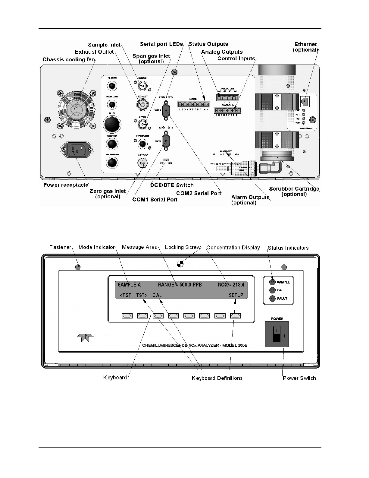
Figure 3-3: M9110EH Rear Panel Layout........................................................................ 12
Figure 3-4: M9110EH Front Panel Layout....................................................................... 12
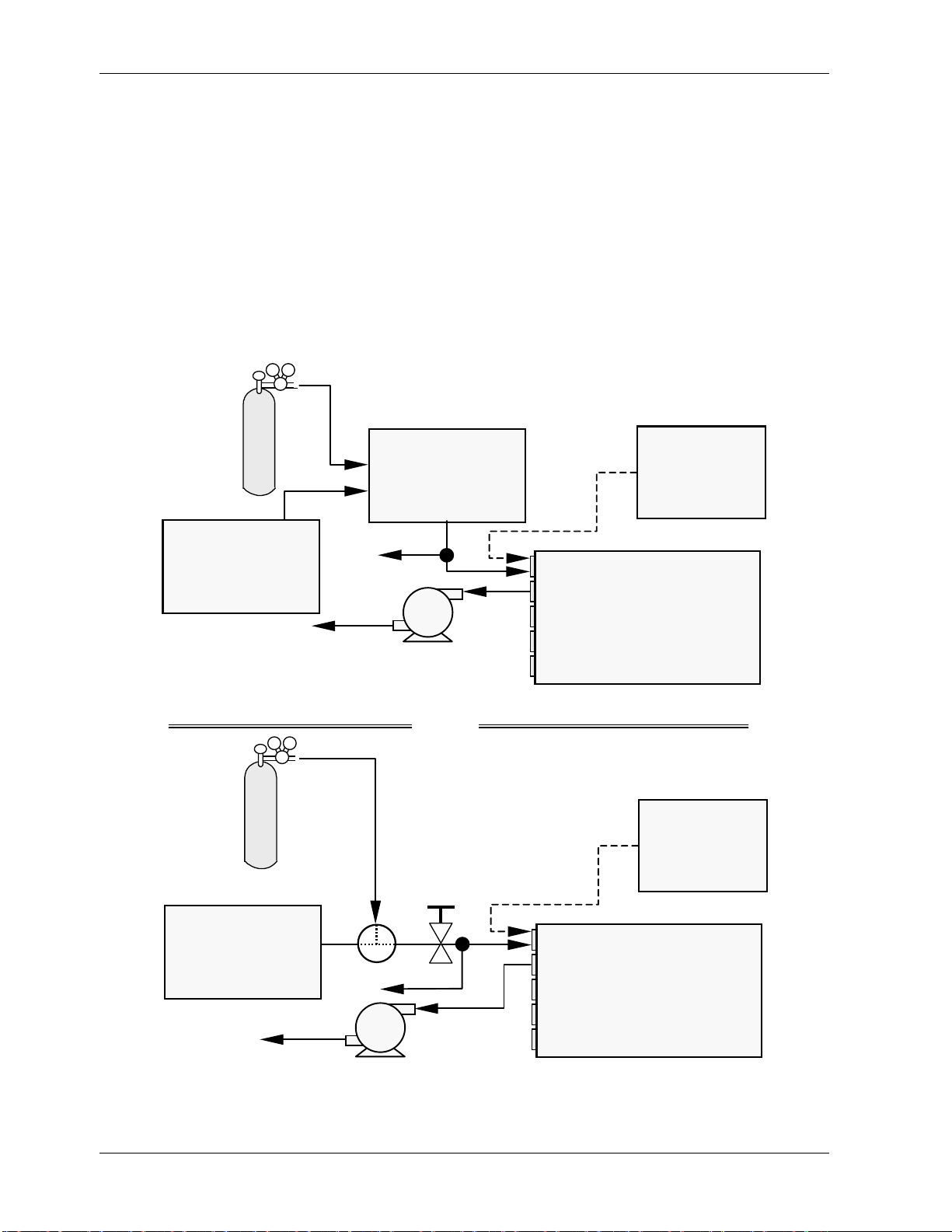
Figure 3-5: Basic Pneumatic Connections for Units Without Valve Options........................... 14
Figure 3-6: Basic Pneumatic Connections for Units With Valve Options ............................... 16
Figure 3-7: Analog Output Connector ............................................................................ 17
Figure 3-8: Status Output Connector............................................................................. 18
Figure 3-9: Control Input Connector.............................................................................. 19
Figure 3-10: Front Panel Display During Startup Sequence................................................. 21
Figure 3-11: M9110EH Pneumatic Diagram In Standard Configuration ................................. 25
Figure 3-12: M9110EH Pneumatic Diagram With Options Installed ...................................... 26
Figure 5-1: M9110EH with Carrying Strap Handle and Rack Mount Brackets........................ 36
Figure 5-2: Current Loop Option Installed on the Motherboard .......................................... 37
Figure 5-3: M9110EH Ethernet Card and Rear Panel With Ethernet Installed ....................... 42
Figure 6-1: Analog Output Connector Key ...................................................................... 52
Figure 6-2: Setup for Calibrating Analog Outputs ............................................................ 68
Figure 6-3: Setup for Calibrating Current Outputs ........................................................... 71
Figure 6-4: Status Output Connector............................................................................. 77
Figure 6-5: Control Inputs with Local and External 5 V Power Supply ................................. 78
Figure 6-6: APICOM Graphical User Interface for Configuring the iDAS ..............................105
Figure 6-7: iDAS Configuration Through a Terminal Emulation Program.............................106
Figure 6-8: APICOM Remote Control Program Interface...................................................111
Figure 7-1: Gas Supply Setup for Determination of NO2 Conversion Efficiency .................... 115
Figure 7-2: Setup for Manual Calibration without Z/S valve or IZS Option.......................... 117
Figure 7-3: Pneumatic Connections for Manual Calibration Checks with IZS........................121
Figure 7-4: Setup for Manual Calibration Check with Z/S Valve or IZS Option..................... 123
Figure 8-1: GPT Calibration System..............................................................................137
Figure 9-1: Sample Particulate Filter Assembly ..............................................................148
Figure 9-2: Particle Filter on O3 Supply Air Dryer............................................................149
Figure 9-3: 04419 Ozone Filter Unit .............................................................................150
Figure 9-4: Zero Air Scrubber Assembly........................................................................154
Figure 9-5: NO2 Converter Assembly ............................................................................155
Figure 9-6: Reaction Cell Assembly ..............................................................................156
Figure 9-7: Critical Flow Orifice Assembly......................................................................158
Figure 10-1: M9110EH Sensitivity Spectrum ...................................................................160
Figure 10-2: NO2 Conversion Principle............................................................................161
Figure 10-3: Reaction Cell with PMT Tube .......................................................................162
Figure 10-4: Reaction Cell During the AutoZero Cycle.......................................................163
Figure 10-5: External Pump Pack...................................................................................166
Figure 10-6: Ozone Generator Principle ..........................................................................168
Figure 10-7: Semi-Permeable Membrane Drying Process...................................................169
Figure 10-8: M9110EH Perma Pure® Dryer......................................................................170
Figure 10-9: Flow Control Assembly & Critical Flow Orifice ................................................172
Figure 10-10: Vacuum Manifold ......................................................................................174
Figure 10-11: Dilution Manifold ....................................................................................... 175
Figure 10-12: M9110EH Electronic Block Diagram..............................................................176
Figure 10-13: M9110EH CPU Board Annotated ..................................................................177
Figure 10-14: Schematic of Basic PMT Design and Functionality...........................................179
Figure 10-15: PMT Preamp Block Diagram ........................................................................181
Figure 10-16: Power Distribution Block Diagram................................................................186
M9110EH Rev 0 ix
Page 10

Model 9110EH Instruction Manual M9110EH Documentation
Figure 10-17: M9110EH Electronic Interface Block Diagram ................................................187
Figure 10-18: Keyboard and Display Interface Block Diagram..............................................189
Figure 10-19: Schematic of Basic Software Operation ........................................................190
Figure 11-1: Viewing and Clearing Warning Messages ......................................................194
Figure 11-2: Switching Signal I/O Functions.................................................................... 196
Figure 11-3: Motherboard Watchdog Status Indicator.......................................................197
Figure 11-4: Relay Board PCA .......................................................................................198
Figure 11-5: Pressure / Flow Sensor Assembly ................................................................217
Figure 11-6: Pre-Amplifier Board Layout.........................................................................224
Figure 11-7: M9110EH Sensor Assembly ........................................................................225
Figure A-1: Basic Sample Display Menu ........................................................................ 230
Figure A-2: Sample Display Menu - Units with Z/S Valve or IZS Option installed .................231
Figure A-3: Primary Setup Menu (Except iDAS)..............................................................232
Figure A-4: Secondary Setup Menu (COMM & VARS)....................................................... 233
Figure A-5: Secondary Setup Menu (DIAG) ...................................................................234
Figure A-6: Internal Data Acquisition (iDAS) Menu .........................................................235
x M9110EH Rev 0
Page 11

Model 9110EH Instruction Manual M9110EH Documentation
LIST OF TABLES
Table 2-1: Model 9110EH Basic Unit Specifications.......................................................... 5
Table 3-1: Inlet / Outlet Connector Nomenclature .......................................................... 13
Table 3-2: Analog Output Pin-Outs............................................................................... 18
Table 3-3: Status Output Signals................................................................................. 18
Table 3-4: Control Input Signals.................................................................................. 19
Table 3-5: Front Panel Display During System Warm-Up ................................................. 21
Table 3-6: Possible Warning Messages at Start-Up ......................................................... 23
Table 5-1: IZS or Z/S Valve States .............................................................................. 38
Table 5-2: Available Permeation Source Options ............................................................ 39
Table 5-3: Contents of Zero Air Scrubber Maintenance Kit............................................... 40
Table 5-4: Dryer and NH3 Removal Options................................................................... 42
Table 6-1: Analyzer Operating modes........................................................................... 45
Table 6-2: Test Functions Defined................................................................................ 47
Table 6-3: List of Warning Messages Revision C.4 .......................................................... 48
Table 6-4: Password Levels......................................................................................... 49
Table 6-5: Variable Names (VARS) Revision C.4............................................................. 59
Table 6-6: M9110EH Diagnostic (DIAG) Functions.......................................................... 61
Table 6-7: DIAG - Analog I/O Functions........................................................................ 64
Table 6-8: Analog Output Voltage Ranges ..................................................................... 64
Table 6-9: Analog Output Current Loop Range............................................................... 65
Table 6-10: Analog Output Pin Assignments.................................................................... 65
Table 6-11: Voltage Tolerances for Analog Output Calibration............................................ 68
Table 6-12: Current Loop Output Calibration with Resistor ................................................ 72
Table 6-13: Test Parameters Available for Analog Output A4 ............................................. 73
Table 6-14: Status Output Pin Assignments .................................................................... 77
Table 6-15: Control Input Pin Assignments ..................................................................... 78
Table 6-16: COM1 and COM2 DB-9 Pin Assignments ........................................................ 81
Table 6-17: COM Port Communication Modes .................................................................. 82
Table 6-18: Ethernet Status Indicators........................................................................... 85
Table 6-19: Front Panel LED Status Indicators for iDAS .................................................... 89
Table 6-20: iDAS Data Channel Properties ...................................................................... 90
Table 6-21: iDAS Data Parameter Functions.................................................................... 91
Table 6-22: M9110EH Default iDAS Configuration, Revision C.7......................................... 93
Table 6-23: Terminal Mode Software Commands ............................................................ 107
Table 6-24: Command Types .......................................................................................108
Table 6-25: Serial Interface Documents ........................................................................112
Table 7-1: IZS Option Valve States with CAL_ON_NO2 Turned ON ...................................121
Table 7-2: AutoCal Modes.......................................................................................... 126
Table 7-3: AutoCal Attribute Setup Parameters.............................................................126
Table 7-4: Example Auto-Cal Sequence ....................................................................... 127
Table 7-5: Calibration Data Quality Evaluation..............................................................129
Table 8-1: Activity Matrix for EPA Calibration Equipment and Supplies .............................132
Table 8-2: Activity Matrix for Calibration Procedure .......................................................132
Table 8-3: Definition of Level 1 and Level 2 Zero and Span Checks..................................140
Table 8-4: Activity Matrix for Data Quality ...................................................................141
Table 9-1: M9110EH Preventive Maintenance Schedule..................................................145
Table 9-2: Predictive Uses for Test Functions................................................................147
Table 10-1: List of Interferents ....................................................................................164
Table 10-2: M9110EH Valve Cycle Phases......................................................................167
Table 10-3: M9110EH Gas Flow Rates...........................................................................172
Table 10-4: Front Panel Status LED’s ............................................................................188
M9110EH Rev 0 xi
Page 12

Model 9110EH Instruction Manual M9110EH Documentation
Table 11-1: Test Functions - Possible Causes for Out-Of-Range Values ..............................195
Table 11-2: Relay Board Status LEDs............................................................................199
Table 11-3: DC Power Test Point and Wiring Color Code .................................................. 210
Table 11-4: DC Power Supply Acceptable Levels............................................................. 211
Table 11-5: Relay Board Control Devices ....................................................................... 212
Table 11-6: Analog Output Test Function - Nominal Values ..............................................213
Table 11-7: Status Outputs Check ................................................................................213
xii M9110EH Rev 0
Page 13

Model 9110EH Instruction Manual M9110EH Documentation
LIST OF APPENDICES
APPENDIX A: SOFTWARE DOCUMENTATION............................................................229
APPENDIX A-1: M9110EH Software Menu Trees and Index, Revision C.8........................... 230
APPENDIX A-2: Setup Variables For Serial I/O, Revision C.8............................................ 236
APPENDIX A-3: Warnings and Test Measurements, Revision C.8 ...................................... 245
APPENDIX A-4: M9110EH Signal I/O Definitions, Revision C.8 ......................................... 247
APPENDIX A-5: M9110EH Trigger Events and iDAS Functions, Revision C.8 ....................... 250
APPENDIX A-6: Terminal Command Designators, Revision C.8......................................... 252
APPENDIX B: SPARE PARTS AND EXPENDABLES .....................................................255
APPENDIX C: REPAIR QUESTIONNAIRE - M200E.....................................................262
APPENDIX D: DIAGRAMS AND SCHEMATICS............................................................264
M9110EH Rev 0 xiii
Page 14

Model 9110EH Instruction Manual M9110EH Documentation
USER NOTES:
xiv M9110EH Rev 0
Page 15

Model 9110EH Instruction Manual M9110EH Documentation
1. M9110EH DOCUMENTATION
1.1. Available Documentation
Thank you for purchasing the Model 9110EH Nitrogen Oxides Analyzer! The documentation for
this instrument is available in different formats:
• Printed format
• Electronic format on a CD-ROM
®
The electronic manual is in Adobe
Adobe
downloaded for free from the internet at http://www.adobe.com/.
®
Acrobat Reader® software, which is necessary to view these files, can be
Systems Inc. “Portable Document Format” (PDF). The
1.2. Manual Structure
1.0 Table of Contents:
Outlines the contents of the manual in the order the information is presented. This is a good
overview of the topics covered in the manual. There is also a list of appendices, figures and
tables. In the electronic version of the manual, clicking on a any of these table entries
automatically views that section.
M9110EH Rev 0 1
Page 16

Model 9110EH Instruction Manual M9110EH Documentation
2.0 Specifications and Warranty
A list of the analyzer’s performance specifications, a description of the conditions and
configuration under which EPA equivalency was approved and T-API’s warranty statement.
3.0 Getting Started
Concise instructions for setting up, installing and running your analyzer for the first time.
4.0 FAQ & Glossary:
Answers to the most frequently asked questions about operating the analyzer and a
glossary of acronyms and technical terms.
5.0 Optional Hardware & Software
A description of optional equipment to add functionality to your analyzer.
6.0 Operation Instructions
Step by step instructions for operating the analyzer.
7.0 Calibration Procedures
General information and step by step instructions for calibrating your analyzer.
8.0 EPA Protocol Calibration
Specific information regarding calibration requirements for analyzers used in EPA-regulated
monitoring applications.
9.0 Instrument Maintenance
Description of preventative maintenance procedures that should be regularly performed on
you instrument to assure good operating condition. This includes information on using the
iDAS to predict possible component failures before they happen.
10.0 Theory of Operation
An in-depth look at the various principals by which your analyzer operates as well as a
description of how the various electronic, mechanical and pneumatic components of the
instrument work and interact with each other. A close reading of this section is invaluable
for understanding the instrument’s operation.
11.0 Troubleshooting & Repair
This section includes pointers and instructions for diagnosing problems with the instrument,
such as excessive noise or drift, as well as instructions on performing repairs of the
instrument’s major subsystems.
Appendices
For easier access and better updating, some information has been separated out of the
manual and placed in a series of appendices at the end of this manual. These include
2 M9110EH Rev 0
Page 17
Model 9110EH Instruction Manual M9110EH Documentation
version-specific software menu trees, warning messages, definitions of iDAS & serial I/O
variables as well as spare part listings, repair questionnaire, interconnect drawing, detailed
pneumatic and electronic schematics.
1.3. How to use this Instruction Manual
Throughout this manual, words printed in capital, bold letters, such as SETUP or ENTR
represent messages as they appear on the analyzer’s front panel display.
The flowcharts in this manual contain typical representations of the analyzer’s display
during the described operations. These representations are not necessarily exact and may
differ slightly from the actual display of your instrument.
NOTE:
Warnings and special notes are called out in bold,
centered frames such as this one.
Cautionary notes with special symbols such as this one may appear
throughout the manual indicating hazardous operations requiring
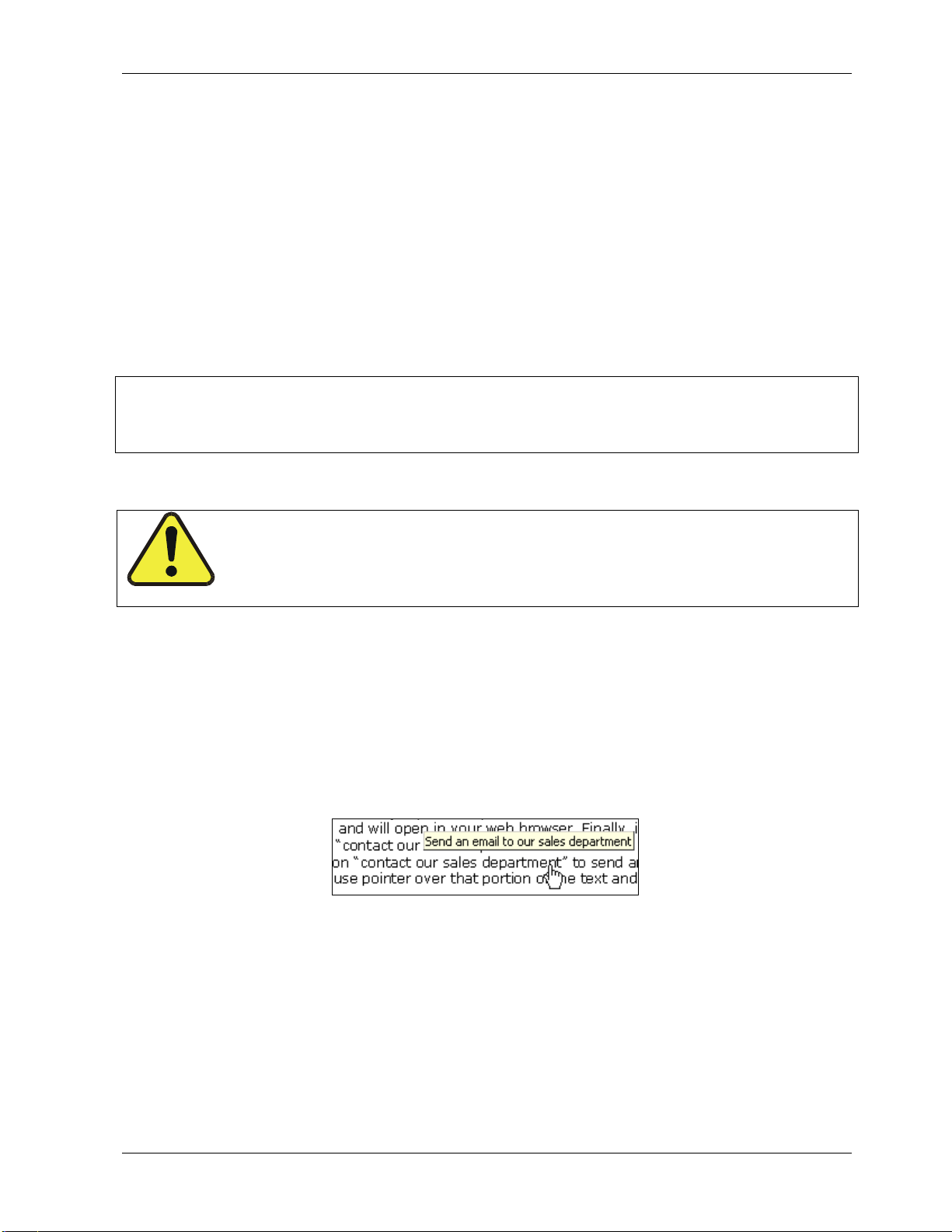
Note that the electronic version of this manual is fully cross-linked. The user can click on
any reference to Figures, Tables and Sections in order to jump to that portion of the
manual, in some instances acronyms are linked to jump to the glossary for explanation.
Likewise, all internet addresses are linked and will open in your web browser. Finally, in
many instances you will find regular text such as “contact our sales department for more
information”, in which case you can click on “contact our sales department” to send an
email to that department. Hover your mouse pointer over that portion of the text and you
should see a pop-up note to that effect like this:
either trained, technical personnel or particular attention.
M9110EH Rev 0 3
Page 18

Model 9110EH Instruction Manual M9110EH Documentation
USER NOTES:
4 M9110EH Rev 0
Page 19

Model 9110EH Instruction Manual M9110EH Documentation
2. SPECIFICATIONS, APPROVALS AND
WARRANTY
2.1. M9110EH Operating Specifications
Table 2-1: Model 9110EH Basic Unit Specifications
Min/Max Range
(Physical Analog Output)
Measurement Units ppb, ppm, µg/m3, mg/m3 (user selectable)
Zero Noise1 0.2 ppb (RMS)
Span Noise1 <0.5% of reading above 50 ppb or 0.2 ppm, whichever is greater
Lower Detectable Limit2 0.4 ppb
Zero Drift (24 hours) <0.5 ppb (at constant temperature and voltage.)
Zero Drift (7 days) 1 ppb (at constant temperature and voltage.)
Span Drift (7 Days) <0.5% of full Scale (at constant temperature and voltage.)
Linearity 1% of full scale
Precision 0.5% of reading
Temperature Coefficient < 0.1% per °C
Voltage Coefficient < 0.1% per V
Lag Time
Rise/Fall Time1 95% in <60 s
Sample Flow Rate 500 cm3/min. ± 10%
Temperature Range 5 - 40 °C operating and EPA equivalency
Humidity Range 0-95% RH non-condensing
Dimensions H x W x D 18 cm x 43 cm x 61 cm (7" x 17" x 23.6")
Weight, Analyzer 18 kg (40 lbs)
Weight, Ext Pump Pack 7 kg (16 lbs)
AC Power Rating 100 V, 50/60 Hz (3.25A);
Power, Ext Pump 100 V, 50/60 Hz (3.25A); 115 V, 60 Hz (3.0 A);
Environmental Installation category (over-voltage category) II; Pollution degree 2
Analog Outputs 4 outputs
Analog Output Ranges All Outputs: 0.1 V, 1 V, 5 V or 10 V (user selectable)
Analog Output Resolution 1 part in 4096 of selected full-scale voltage (12 bit)
Status Outputs 8 Status outputs from opto-isolators, 7 defined, 1 spare
Control Inputs 6 Control inputs, 4 defined, 2 spare
Serial I/O 1 RS-232; 1 RS-485 or RS-232 (configurable)
Certifications USEPA: Reference Method Number RFNA 1194-099
1
As defined by the USEPA.
2
Defined as twice the zero noise level by the USEPA.
1
Min: 0-50 ppb
Max: 0-20 ppm
20 s
115 V, 60 Hz (3.0 A);
220 - 240 V, 50/60 Hz (2.5 A)
220 - 240 V, 50/60 Hz (2.5 A)
Three outputs convertible to 4-20 mA isolated current loop.
All Ranges with 5% under/over range
Communication speed: 300 - 115200 baud (user selectable)
CE: EN61326 (1997 w/A1: 98) Class A, FCC Part 15 Subpart B Section
15.107 Class A, ICES-003 Class A (ANSI C63.4 1992) & AS/NZS 3548
(w/A1 & A2; 97) Class A.
M9110EH Rev 0 5
Page 20

Specifications, Approvals and Warranty Model 9110EH Instruction Manual
2.2. EPA Equivalency Designation
The Model 9110EH Analyzer is designated as Reference Method Number RFNA-1194-099
(same designation as model M9110EH) as per 40 CFR Part 53 when operated under the
following conditions:
• Range: Any full-scale range between 0-0.05 and 0-1.0 ppm (parts per million).
• Ambient temperature range of 5
to 40 oC.
• Line voltage range of 105-125 VAC or 220-240 VAC, at 50 or 60 Hz.
• Equipped with PTFE filter element in the internal filter assembly.
• Equipped with ozone supply air filter
External vacuum pump capable of 10 in-Hg-A at 2 standard liters per minute (slpm) or
better.
Software settings:
Dynamic span OFF
Dynamic zero OFF
Cal-on-NO
OFF
2
Dilution factor OFF
Temp/Pressure compensation ON
AutoCal ON or OFF
Independent range ON or OFF
Auto-range ON or OFF
Converter efficiency Acceptable values of 0.96 to 1.02
Under the designation, the analyzer may be operated with or without the following optional
equipment:
• Rack mount with or without slides.
• Rack mount for external pump.
• Zero/span valve options.
• Nafion-type permeation sample gas conditioner
• Internal zero/span (IZS) option with:
• NO
• NO
permeation tube - 0.4ppm at 0.7 liter per minute; certified/uncertified.
2
permeation tube - 0.8 ppm at 0.7 liter per minute; certified/uncertified.
2
Under the designation, the IZS option cannot be used as the source of calibration.
• 4-20mA isolated analog outputs.
• Status outputs.
• Control inputs.
• RS-232 output.
• Ethernet communications option
6 M9110EH Rev 0
Page 21

Model 9110EH Instruction Manual Specifications, Approvals and Warranty
2.3. CE Mark Compliance
The Teledyne-Analytical Instruments Nitrogen Oxides Analyzers M9110EH
were tested and found to be fully compliant with:
EN61326 (1997 w/A1: 98) Class A, FCC Part 15 Subpart B Section 15.107 Class A,
ICES-003 Class A (ANSI C63.4 1992) & AS/NZS 3548 (w/A1 & A2; 97) Class A.
Tested on January 02-06, 2003 at CKC Laboratories, Inc., Report Number CE03-005.
The Teledyne-Advanced Pollution Instrumentation Nitrogen Oxides Analyzers M200E,
M200EH and M200EM were tested and found to be fully compliant with:
EN61010-1 (2001)
Tested on January 27-20, 2003.
2.4. Warranty
Warranty Policy (02024C)
Prior to shipment, TAI equipment is thoroughly inspected and tested. Should equipment
failure occur, TAI assures its customers that prompt service and support will be available.
Coverage
After the warranty period and throughout the equipment lifetime, TAI stands ready to
provide on-site or in-plant service at reasonable rates similar to those of other manufacturers in the industry. All maintenance and the first level of field troubleshooting is to be
performed by the customer.
Non-TAI Manufactured Equipment
Equipment provided but not manufactured by TAI is warranted and will be repaired to the
extent and according to the current terms and conditions of the respective equipment
manufacturers warranty.
General
TAI warrants each product manufactured by TAI to be free from defects in material and
workmanship under normal use and service for a period of one year from the date of
delivery. All replacement parts and repairs are warranted for 90 days after the purchase.
If a product fails to conform to its specifications within the warranty period, TAI shall
correct such defect by, in TAI's discretion, repairing or replacing such defective product or
refunding the purchase price of such product.
The warranties set forth in this section shall be of no force or effect with respect to any
product: (i) that has been altered or subjected to misuse, negligence or accident, or (ii)
that has been used in any manner other than in accordance with the instruction provided by
TAI or (iii) not properly maintained.
M9110EH Rev 0 7
Page 22

Specifications, Approvals and Warranty Model 9110EH Instruction Manual
THE WARRANTIES SET FORTH IN THIS SECTION AND THE REMEDIES THEREFORE ARE
EXCLUSIVE AND IN LIEU OF ANY IMPLIED WARRANTIES OF MERCHANTABILITY, FITNESS
FOR PARTICULAR PURPOSE OR OTHER WARRANTY OF QUALITY, WHETHER EXPRESSED OR
IMPLIED. THE REMEDIES SET FORTH IN THIS SECTION ARE THE EXCLUSIVE REMEDIES
FOR BREACH OF ANY WARRANTY CONTAINED HEREIN. TAI SHALL NOT BE LIABLE FOR
ANY INCIDENTAL OR CONSEQUENTIAL DAMAGES ARISING OUT OF OR RELATED TO THIS
AGREEMENT OF TAI'S PERFORMANCE HEREUNDER, WHETHER FOR BREACH OF
WARRANTY OR OTHERWISE.
Terms and Conditions
All units or components returned to TAI should be properly packed for handling and
returned freight prepaid to the nearest designated Service Center. After the repair, the
equipment will be returned, freight prepaid.
8 M9110EH Rev 0
Page 23

Model 9110EH Instruction Manual Getting Started
3. GETTING STARTED
3.1. Unpacking and Initial Setup
CAUTION
The M9110EH weighs about 17 kg (40 pounds) without options installed. To avoid
personal injury, we recommend to use two persons to lift and carry the analyzer.
Inspect the received packages for external shipping damage. If damaged, please advise the
shipper first, then TAI.
Included with your analyzer is a printed record (Form number 04490) of the final performance characterization performed on your instrument at the factory. This record is an
important quality assurance and calibration record for this instrument. It should be placed
in the quality records file for this instrument.
• Carefully remove the top cover of the analyzer and check for internal shipping
damage.
• Remove the set screw located in the top, center of the rear panel.
• Remove the screws fastening the top cover to the unit (four per side).
• Lift the cover straight up.
CAUTION
Printed Circuit Assemblies (PCA) are static sensitive. Electrostatic discharges, too
small to be felt by humans, are large enough to destroy sensitive circuits.
Before touching a PCA, fasten a properly installed grounding strap to your wrist or
touch a bare metal part of the chassis to discharge any electrostatic potentials.
Never disconnect electronic circuit boards, wiring harnesses or electronic
subassemblies while the unit is under power.
Do not position the equipment so that it is difficult to operate the disconnecting
device.
• Inspect the interior of the instrument to make sure all circuit boards and other
components are in good shape and properly seated.
• Check the connectors of the various internal wiring harnesses and pneumatic hoses
to make sure they are firmly and properly seated.
• Verify that all of the optional hardware ordered with the unit has been installed.
These are checked on the paperwork (Form 04490) accompanying the analyzer.
• Once you have determined that no shipping damage exists and the unit includes all
expected hardware options, remove three, red colored shipping screws from the
bottom of the chassis, shown in Figure 3-1.
M9110EH Rev 0 9
Page 24
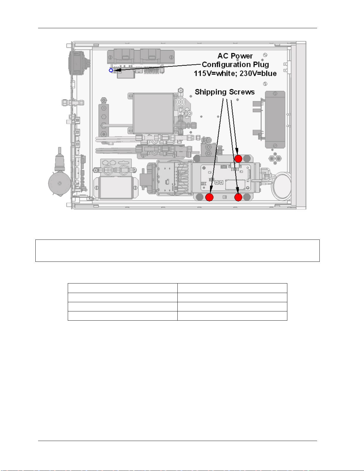
Getting Started Model 9110EH Instruction Manual
Figure 3-1: Location of Shipping Screws and Power Configuration Plug
NOTE
Save these shipping screws and re-install them whenever the unit is shipped.
A certain ventilation clearance is required for the operation of the analyzer:
Area Minimum required clearance
Back of the instrument 10 cm / 4 inches
Sides of the instrument 2.5 cm / 1 inch
Above and below the instrument 2.5 cm / 1 inch
Various rack mount kits are available for this analyzer. See Chapter 5 of this manual for
more information.
10 M9110EH Rev 0
Page 25
Model 9110EH Instruction Manual Getting Started
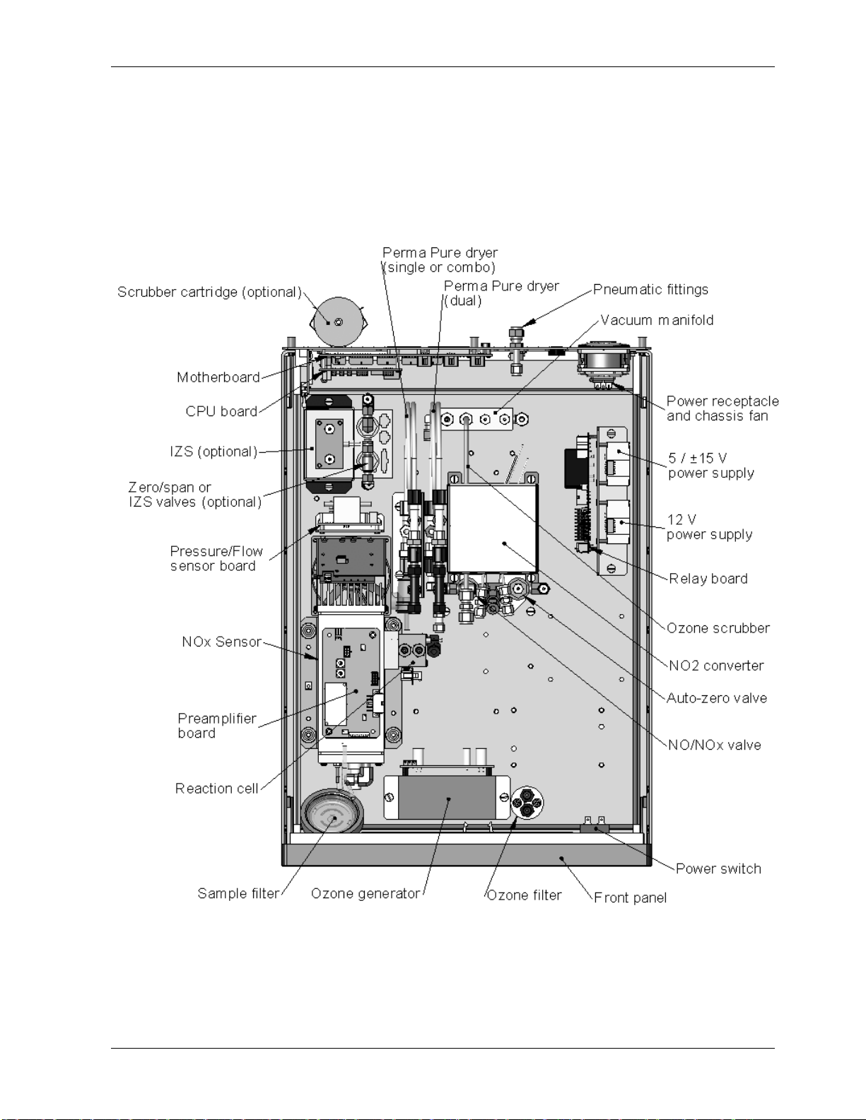
3.2. M9110EH Layout
Figure 3-2 shows a top-down view of the analyzer. The shown configuration includes the
Ethernet board, IZS option, zero-air scrubber and an additional sample dryer. See
Chapter 5 for optional equipment. Figure 3-3 shows the rear panel configuration with
optional zero-air scrubber mounted to it and two optional fittings for the IZS option. Figure
3-4, finally shows the front panel layout of the analyzer.
Figure 3-2: M9110EH Layout
M9110EH Rev 0 11
Page 26
Getting Started Model 9110EH Instruction Manual
9110EH
Figure 3-3: M9110EH Rear Panel Layout
Figure 3-4: M9110EH Front Panel Layout
12 M9110EH Rev 0
Page 27
Model 9110EH Instruction Manual Getting Started
3.3. Pneumatic Connections
Sample and calibration gases should only come into contact with PTFE (Teflon), FEP, glass
or stainless steel materials. Figure 3-5 and Figure 3-6 illustrate the most common
configurations for gas supply and exhaust lines to the Model 9110EH Analyzer. Appendix D
contains more detailed pneumatic flow diagrams for the analyzer and its various
(pneumatically related) options.
CAUTION
To prevent dust from getting into the analyzer, it was shipped with small plugs
inserted into each of the pneumatic fittings on the rear panel. Make sure that all
dust plugs are removed before attaching exhaust and supply gas lines.
Please refer to Figure 3-3 for pneumatic connections at the rear panel and Table 3-1 for
nomenclature.
Table 3-1: Inlet / Outlet Connector Nomenclature
Rear Panel Label Function
Sample
Exhaust Connects the exhaust of the analyzer with the external vacuum pump.
Span
Zero Air
Connects the sample gas to the analyzer. When operating the analyzer
without zero span option, this is also the inlet for any calibration gases.
On Units with zero/span valve or IZS option installed, this port
connects the external calibration gas to the analyzer.
On Units with zero/span valve or IZS option installed, this port
connects the zero air gas or the zero air cartridge to the analyzer.
• Attach a sample inlet line to the sample inlet port. Ideally, the pressure of the
sample gas should be equal to ambient atmospheric pressure.
• In applications where the sample gas is received from a pressurized manifold, a vent
must be provided to equalize the sample gas with ambient atmospheric pressure
before it enters the analyzer. The vented gas needs to be routed outside the immediate area or shelter surrounding the instrument.
CAUTION
Maximum pressure of any gas at the sample inlet should not exceed 1.5 in-Hg
above ambient pressure and ideally should equal ambient atmospheric pressure.
CAUTION
The exhaust from the external pump needs to be vented outside the
immediate area or shelter surrounding the instrument using a
maximum of 10 meters of 1/4” PTFE tubing.
M9110EH Rev 0 13
Page 28
Getting Started Model 9110EH Instruction Manual
• Attach the 1/4" exhaust line to the exhaust port of the analyzer and to the inlet port
of the pump.
• Attach zero air and span gas supply lines as appropriate (Figure 3-5 and Figure 3-6)
to the rear panel (Figure 3-3). For this type of analyzer, zero air and span gas are
defined as follows.
3.3.1. Span Gas Defined
Span gas is defined as a gas specifically mixed to match the chemical composition of the
type of gas being measured at near full scale of the desired measurement range. To
measure NO
with an NO
with the M9110EH NOX Analyzer, it is recommended that you use a span gas
X
concentration equal to 80% of the measurement range for your application.
Calibrated
NO gas
concentration)
Calibrated
NO gas
(At span gas
concentration)
(high
MODEL 701
Zero Air
Generator
No Valve Options Installed
MODEL 700 Gas
Dilution
Calibrator
(with Ozone generator
option)
VENT
Pump
Sample
Exhaust
Span
Source of
SAMPLE gas
removed
during
calibration
MODEL
9110EH
Zero Air
OR
Needle valve to
control flow
Source of
SAMPLE gas
removed
during
calibration
Valve
MODEL 701
Zero Air
Generator
Sample
VENT
Exhaust
Span
MODEL
9110EH
Pump
Figure 3-5: Basic Pneumatic Connections for Units Without Valve Options
14 M9110EH Rev B
Zero Air
Page 29

Model 9110EH Instruction Manual Getting Started
For example, if the measurement is NOX in ambient air between 0 and 500 ppb, an
appropriate span gas would be NO in air at 400 ppb NO concentration (80% of maximum
range). Even though NO gas in nitrogen could be used as a span gas, the matrix of the
balance gas is different and may cause interference problems or yield incorrect calibrations.
The same applies to gases that contain high concentrations of other compounds (for
example, CO
or H2O). The span gas should match all concentrations of all gases of the
2
measured medium as closely as possible.
Cylinders of calibrated NO gas traceable to NIST-standard reference materials specifications
(also referred to as EPA protocol calibration gases) are commercially available.
Some applications, such as EPA monitoring, require a multipoint calibration where span
gases of different concentrations are needed. We recommend using an NO gas of higher
concentration combined with a gas dilution calibrator such as a T-API Model 700. This type
of calibrator mixes a high concentration gas with zero air (both supplied externally) to
accurately produce span gas of the desired concentration. Linearity profiles can be
automated with this model and run unattended overnight. The dynamic range of the M700
is about 0.1 to 0.001 times the original span concentration.
If a dynamic dilution system such as the TAI model 700 is used to dilute high concentration gas standards to low, ambient concentrations, ensure that the NO concentration of the
reference gas matches the dilution range of the calibrator. Choose the NO gas concentration
such that the dynamic dilution system operates in its mid-range and not at the extremes of
its dilution capabilities. For example, a dilution calibrator with 10-10000 dilution ratio will
not be able to accurately dilute a 5000 ppm NO gas to a final concentration of 500 ppb, as
this would operate at the very extreme dilution setting. A 100 ppm NO gas in nitrogen is
much more suitable to calibrate the M9110EH analyzer (dilution ratio of 222, in the mid-range
of the system’s capabilities).
3.3.2. Zero Gas Defined
Zero air or zero calibration gas is defined as a gas that is similar in chemical composition to
the measured medium but without the gas to be measured by the analyzer, in this case NO
and NO
capable of creating zero air from ambient air. However, if your application is not a
measurement in ambient air, the zero calibration gas should be matched to the matrix of
the measured medium. Pure nitrogen could be used as a zero gas for applications where
NO
For analyzers without zero air options, a zero air generator such as the TAI Model 701 can
be used. Please visit the company website for more information.
If your analyzer is equiped with either the zero/span valve option (Option 50) or the
internal zero/span option (Option 51), the pneumatic connections should be made as shown
in Figure 3-6 (see also Appendix D for detailed diagram).
. If your analyzer is equipped with an IZS or external zero air scrubber option, it is
2
is measured in nitrogen.
X
M9110EH Rev 0 15
Page 30
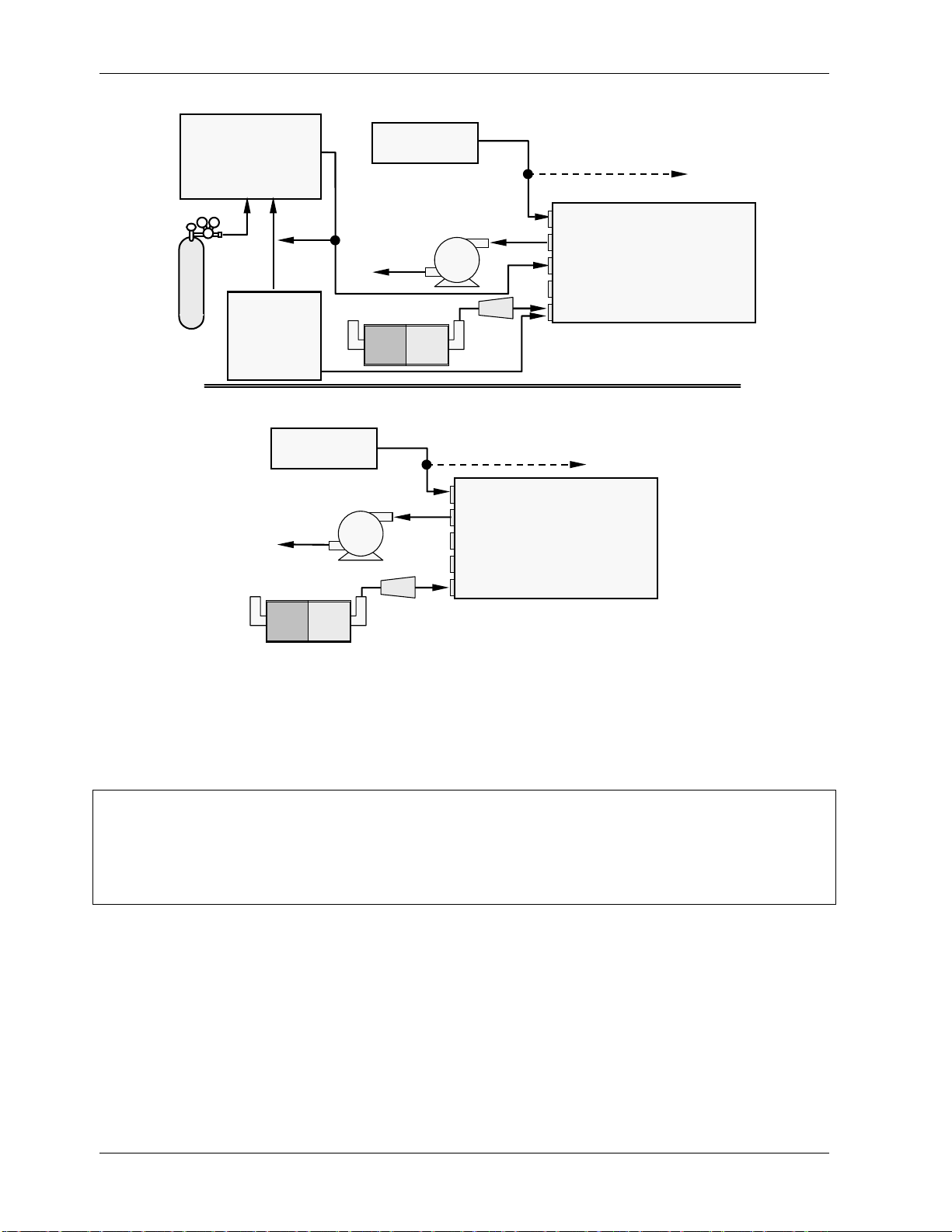
Getting Started Model 9110EH Instruction Manual
MODEL 700
Gas Dilution Calibrator
(with O3 generator option)
Calibrated
NO gas
(high
concentration)
VENT
MODEL 701
Zero Air
Generator
Source of
SAMPLE Gas
External Zero
Air Scrubber
Pump
Source of
SAMPLE Gas
Pump
Internal Zero/Span Option (IZS) – Option 51
VENT if input is pressurized
Sample
Exhaust
Span
Filter
Zero/Span Valves – Option 50
VENT if input is pressurized
Sample
Exhaust
Span
Zero Air
MODEL
9110EH
MODEL
9110EH
External Zero
Air Scrubber
Particulate
Filter
Zero Air
Figure 3-6: Basic Pneumatic Connections for Units With Valve Options
Once the appropriate pneumatic connections have been made, check all pneumatic fittings
for leaks using the procedures defined in Section 11.5.
WARNING
Gas flow must be maintained at all times for units with IZS Options installed. The
IZS option includes a permeation tube which emits NO2. Insufficient gas flow can
build up NO2 to levels that will damage the instrument. Remove the permeation
device when taking the analyzer out of operation.
16 M9110EH Rev 0
Page 31

Model 9110EH Instruction Manual Getting Started
3.4. Electrical Connections
Refer to Figure 3-3 for the location of the rear panel electrical and pneumatic connections.
3.4.1. Power Connection
Attach the power cord to the analyzer and plug it into a power outlet capable of carrying at
least 10 A current at your AC voltage and that it is equipped with a functioning earth
ground.
The M9110EH analyzer can be configured for both 100-130 V and 210-240 V at either 50 or 60
Hz., To avoid damage to your analyzer, make sure that the AC power voltage matches the
voltage indicated on the rear panel serial number label and that the frequency is between
47 and 63 Hz. Refer to Figure 3-1 to locate and identify the power configuration plug if
necessary.
If you need to reconfigure your analyzer for one of the other voltage ranges, contact the
factory for an optional power configuration jumper (shown in Figure 3-1)
CAUTION
The correct voltage and frequency needs to be supplied to the analyzer
as listed on the label on the rear panel of the instrument .
Power connections must have a functioning ground connection.
3.4.2. Analog Output Connections
Attach a strip chart recorder and/or data-logger to the appropriate contacts of the analog
output connecter on the rear panel of the analyzer.
A1 A2 A3 A4
+ - + - + - + -
Figure 3-7: Analog Output Connector
Output channels A1, A2 and A3 are assigned to the
signals of the analyzer. The output labeled A4 can be set by the user for output of any test
parameter accessible through the <TST TST> keys on the front panel display. Section 6.7.4
describes how to change that setting.
ANALOG OUT
NOX, NO and NO
concentration
2
Optional current loop outputs are available for analog output channels A1-A3. Pin-outs for
the analog output connector at the rear panel of the instrument are listed in Table 3-2.
The default analog output voltage setting of the M9100EH is 0 - 5 VDC with a range of
0-500 ppb. To change these settings, see Sections 6.5 and 6.7.3.
M9110EH Rev 0 17
Page 32

Getting Started Model 9110EH Instruction Manual
K
Table 3-2: Analog Output Pin-Outs
Pin Analog Output Data Type Voltage Signal Current Signal
1 V Out I Out +
A1 NO
2
3 V Out I Out +
A2 NO
4
5 V Out I Out +
A3 NO
6
7 V Out not available
A4 Test Channel
8
X
Ground I Out -
Ground I Out -
2
Ground I Out -
Ground not available
If you wish to utilize the analyzer’s status outputs to interface with a device that accepts
logic-level digital inputs, such as programmable logic controller (PLC) chips, you can access
them through a 12 pin connector on the analyzer’s rear panel labeled STATUS.
1 2 3 4 5 6 7 8 D +
SYSTEM O
CONC VALID
HIGH RANGE
STATUS
ZERO CAL
SPAN CAL
DIAGNOSTIC
MODE
LOW SPAN
FOR PINS 1-8
EMITTER BUS
Figure 3-8: Status Output Connector
Table 3-3: Status Output Signals
Pin # Status Condition (ON = Conducting)
1 SYSTEM OK ON if no faults are present.
2 CONC VALID ON if concentration measurement (NO, NO2 or NOx) is valid.
OFF any time the hold-off feature is active.
3 HIGH RANGE ON if unit is in high range of the Auto Range Mode.
4 ZERO CAL ON whenever the instrument is in ZERO point calibration mode.
5 SPAN CAL ON whenever the instrument is in SPAN point calibration mode.
6 DIAG MODE ON whenever the instrument is in diagnostic mode.
7 Unused
8 Unused
D EMITTER BUS The emitters of the transistors on pins 1-8 are tied together.
Unused
+ DC POWER + 5 VDC, 300 mA (combined rating with Control Output, if used).
Digital
Ground
The ground level from the analyzer’s internal DC power supplies
18 M9110EH Rev 0
Page 33

Model 9110EH Instruction Manual Getting Started
L
L
L
L
If you wish to use the analyzer to remotely activate the zero and span calibration modes,
several digital control inputs are provided through a 10-pin connector labeled CONTROL IN
on the analyzer’s rear panel.
There are two methods for energizing the control inputs. The internal +5V available from
the pin labeled “+” is the most convenient method. However, if full isolation is required, an
external 5 VDC power supply should be used.
A B C D E F U
ZERO CA
SPAN CA
CONTROL IN
Local Power Connections
CONTROL IN
+
A B C D E F U
ZERO CA
SPAN CA
5 VDC Power
Supply
-
External Power Connections
+
Figure 3-9: Control Input Connector
Table 3-4: Control Input Signals
Input # Status Definition ON Condition
A REMOTE ZERO CAL The analyzer is placed in Zero Calibration mode. The mode
field of the display will read ZERO CAL R.
B REMOTE SPAN CAL The analyzer is placed in low span calibration mode as part
of performing a low span (midpoint) calibration. The mode
field of the display will read LO CAL R.
C SPARE
D SPARE
E SPARE
F SPARE
U External Power input Input pin for +5 VDC required to activate pins A - F.
+ 5 VDC output Internally generated 5V DC power. To activate inputs A - F,
Digital Ground The ground level from the analyzer’s internal DC power
supplies (same as chassis ground).
place a jumper between this pin and the “U” pin. The
maximum amperage through this port is 300 mA (combined
with the analog output supply, if used).
+
If you wish to utilize one of the analyzer’s two serial ports, attach the serial cable that is
included with the analyzer to the COM1 serial port on the rear panel. Connect the other end
to a serial port on your computer and set the computer serial port to 115000 baud transfer
M9110EH Rev 0 19
Page 34

Getting Started Model 9110EH Instruction Manual
speed, 8 data bits, no parity, 1 stop bit and Xon/Xoff flow control. Use the APICOM remote
control software that was included with the analyzer to connect to the instrument or use
any terminal emulation program. Refer to Section 6.9 of this manual for instructions on
configuration and usage of the serial port, Section 6.11 for remote operation of the
analyzer.
3.4.3. Ethernet Connection and Configuration
If your M9110EH is equipped with an Ethernet option (described in Section 5.8.3), the
analyzer needs to be configured to match the network settings of your internal network.
Please change the first three of the following parameters to configure the Ethernet
functionality:
• (IP) A static IP address (default value is 000.000.000.000).
• (GTWY) A static network gateway IP address (default is 000.000.000.000).
• (SNET) A subnet mask (default is 255.255.255.0).
• (PORT) A TCP/IP port number (default is 3000, does not need to be changed).
Note that the M9110EH currently does not support DHCP or dynamic IP addresses. All of the
above settings can be changed by following the procedure described in Section 6.9.9 of this
manual. To do this quickly, press the following keys on the analyzer’s front panel: SETUP
– MORE – COMM – INET and configure the individual items shown on the menu and listed
above.
3.5. Initial Operation
If you are unfamiliar with the theory of operation of the M9110EH analyzer, we recommend
that you read Chapter 10 before proceeding. For information on navigating the analyzer’s
software menus, see the menu trees described in Appendix A.1.
3.5.1. Startup
After electrical and pneumatic connections are made, turn on the instrument and supply
power to the external pump. The exhaust and PMT cooler fans should start. The display
should immediately display a single, horizontal dash in the upper left corner of the display.
This will last approximately 30 seconds while the CPU loads the operating system. Once the
CPU has completed this activity, it will begin loading the analyzer firmware and configuration data. During this process, a string of messages will appear on the analyzer’s front panel
display as shown in Figure 3-10. The analyzer should automatically switch to SAMPLE
mode after completing the boot-up sequence and start monitoring NO
, NO, NO2 gases.
X
20 M9110EH Rev 0
Page 35

Model 9110EH Instruction Manual Getting Started
SELECT DESIRED FUNCTION : 3
START .
CHECKING FLASH STATUS : 2
STARTING INSTRUMENT CODE : 1
STARTING INSTRUMENT W/FLASH : 1
M200E NOX ANALYZER
BOOT PROGRESS [XXXXX 50%_ _ _ _ _]
System waits 3 seconds then
automatically begins its initialization
routine. No action required.
System is checking the format of
the instrument’s flash memory chip.
If at this point,
**FLASH FORMAT INVALID**
appears, contact T–API customer
The instrument is loading
configuration and calibration data
The instrument is loading the
service
from the flash chip
analyzer firmware.
SOFTWARE REVISION C.4
BOOT PROGRESS [XXXXXXXX 80% _ _]
SAMPLE SYSTEM RESET NOX=X.X
TEST CAL CLR SETUP
The revision level of the firmware
installed in your analyzer is briefly
displayed
Firmware
fully booted
Press CLR to clear initial warning messages.
(see Section 3.2.3)
Figure 3-10: Front Panel Display During Startup Sequence
3.5.2. Warm-Up
The M9110EH requires about 30 minutes warm-up time before reliable NOX, NO and NO
measurements can be taken. During that time, various portions of the instrument’s front
panel will behave as follows. See Figure 3-4 for locations.
Table 3-5: Front Panel Display During System Warm-Up
Name Color Behavior Significance
Concentration Field
N/A
Mode Field N/A
Switches between
NOX, NO and NO2
Displays blinking
“SAMPLE”
This is normal operation.
Instrument is in sample mode but is still in the
process of warming up (hold-off period is
active).
2
M9110EH Rev 0 21
Page 36

Getting Started Model 9110EH Instruction Manual
p p
Name Color Behavior Significance
STATUS LEDs
Sample Green On
Cal Yellow Off The instrument’s calibration is not enabled.
Fault Red Blinking
Unit is operating in sample mode, front panel
display is continuously updated.
The analyzer is warming up and out of
specification for a fault-free reading.
3.5.3. Warning Messages
During warm-up, internal temperatures and other parameters may be outside of specified
limits. The software will suppress most warning conditions for 30 minutes after power up.
The following table includes a brief description of the various warning messages that may
appear after the warm-up time. If warning messages persist after 30 minutes, investigate
their cause using the troubleshooting guidelines in Chapter 11. To view and clear warning
messages, use the following key strokes:
SAMPLE HVPS WARNING NOX = 0.0
TEST
CAL MSG CLR SETUP
SAMPLE
RANGE=500.0 PPB
NO = 0.0
< TST TST > CAL
SAMPLE
HVPS WARNING
MSG
CLR SETUP
NOX = 0.0
TEST CAL MSG
NOTE:
If the warning message persists after several attempts to
clear it, the message may indicate a real problem and not
an artifact of the warm-u
eriod
CLR
SETUP
TEST deactivates warning
messages
activates warning
MSG
messages.
<TST TST> keys replaced with
TEST key
Press CLR to clear the current
message.
If more than one warning is active, the
next message will take its place
Once the last warning has been
cleared, the analyzer returns to
SAMPLE mode
22 M9110EH Rev 0
Page 37

Model 9110EH Instruction Manual Getting Started
Table 3-6: Possible Warning Messages at Start-Up
Message Definition
ANALOG CAL WARNING The instrument’s A/D circuitry or one of its analog outputs is not
calibrated.
AZERO WRN XXX.X MV The reading taken during the auto-zero cycle is outside of specified limits.
The value XXX.X indicates the auto-zero reading at the time of the
warning.
BOX TEMP WARNING The temperature inside the M200E chassis is outside the specified limits.
CANNOT DYN SPAN Remote span calibration failed while the dynamic span feature was ON
CANNOT DYN ZERO Remote zero calibration failed while the dynamic zero feature was ON.
CONFIG INITIALIZED Configuration was reset to factory defaults or was erased.
CONV TEMP WARNING NO2 converter temperature is outside of specified limits.
DATA INITIALIZED iDAS data and settings were erased.
HVPS WARNING High voltage power supply for the PMT is outside of specified limits.
IZS TEMP WARNING On units with IZS options installed: The permeation tube temperature is
outside of specified limits.
OZONE FLOW WARNING Ozone flow is outside of specified limits.
OZONE GEN OFF Ozone generator is off, which is intentional for the warm-up period. This
is the only warning message that automatically clears itself after warmup.
PMT TEMP WARNING PMT temperature is outside of specified limits.
RCELL PRESS WARN Reaction cell pressure is outside of specified limits.
RCELL TEMP WARNING Reaction cell temperature is outside of specified limits.
MANIFOLD TEMP WARN Dilution or bypass manifold temperature is outside of warning limits (if
installed).
REAR BOARD NOT DET The CPU is unable to communicate with the motherboard.
RELAY BOARD WARN The firmware is unable to communicate with the relay board.
SAMPLE FLOW WARN The flow rate of the sample gas is outside the specified limits.
SYSTEM RESET This message appears every time the analyzer was powered up.
3.5.4. Functional Check
After the analyzer’s components have warmed up for at least 30 minutes, verify that the
software properly supports any hardware options that were installed.
Check to make sure that the analyzer is functioning within allowable operating parameters.
Appendix A and C include a list of test functions viewable from the analyzer’s front panel as
well as their expected values. These functions are also useful tools for diagnosing performance problems with your analyzer (Chapter 11). The enclosed Final Test and Validation Data
Sheet (part number 04490) lists these values before the instrument left the factory. To
view the current values of these test functions press the <TST TST> keys:
M9110EH Rev 0 23
Page 38

Getting Started Model 9110EH Instruction Manual
1
g
SAMPLE RANGE = 500.0 PPB NOX = X.X
< TST TST >
Toggle
scroll throu
2
Only appears if analyzer is set
<TST TST>
h list of functions
Only appears if IZS option is
installed.
to display NO, NO
CAL SETUP
keys to
, NOx
2
simultaneously in message
field.
3
Only appears if analog autput
A4 is actively reporting a test
function
RANGE
NOX STB
SAMP FLW
OZONE FL
PMT
NORM PMT
AZERO
HVPS
RCELL TEMP
BOX TEMP
PMT TEM
IZS TEMP1
MOLY TEMP
RCEL
SAMP
NOX SLOPE
NOX OFFS
NO SLOPE
NO OFFS
2
NO2
2
NOX
2
NO
3
TEST
TIME
Refer to
Section
6.2.1 for
definitions
of these
test
functions.
Figure 3-11 and Figure 3-12 show the analyzer flow diagrams without and with options
installed. Refer to these diagrams whenever troubleshooting or a thorough understanding of
the analyzer operation is required. Note that valve options for zero/span valves or IZS are
principally the same, except that the span gas stream is connected differently in the
zero/span option.
More detailed pneumatic diagrams for all configurations (base, zero/span valves, IZS,
sample dryer) can be found in Appendix D, diagram number 04574.
24 M9110EH Rev 0
Page 39

Model 9110EH Instruction Manual Getting Started
Figure 3-11: M9110EH Pneumatic Diagram In Standard Configuration
M9110EH Rev 0 25
Page 40

Getting Started Model 9110EH Instruction Manual
Figure 3-12: M9110EH Pneumatic Diagram With Options Installed
26 M9110EH Rev 0
Page 41

Model 9110EH Instruction Manual Getting Started
3.6. First Calibration
3.6.1. Basic Calibration Procedure
The initial calibration should be carried out using the 500 ppb range, a span gas with about
400 ppb NO and with the unit set for SINGLE range, which will enable you to compare your
calibration results to the factory calibration as listed on the Final Test and Validation Data
Sheet. The following three-step procedure assumes that the instrument does not have any
of the available zero/span (Z/S) valve options installed. Chapter 7 contains instructions for
calibrating instruments with Z/S valve options, Chapter 8 for EPA protocol calibration.
Set the analog output range of the M200E:
SAMPLE RANGE = 500.0 PPB NOX= X.X
< TST TST > CAL
SETUP X.X
CFG DAS
SETUP X.X
MODE
SETUP X.X
0 0 5
SETUP X.X RANGE:
0 0 0 5 0 .0
RNGE
RANGE CONTROL MENU
SET UNIT
PASS CLK MORE EXIT
EXIT
RANGE: 500.0 CONC
0 0 .
500.0 Conc
0 ENTR EXIT
ENTR EXIT
SETUP
Press this button to set
IND
SNGL
ranges
.
the analyzer for
or
DUAL
Press this button to select the
concentration units of measure:
PPB, PPM, UGM, MGM
To change the value of the reporting
range span, change the numbers by
pressing the keys under each digit.
ignores the new setting and returns
EXIT
to the
RANGE CONTROL MENU. ENTR
accepts the new setting and returns to the
RANGE CONTROL MENU
M9110EH Rev 0 27
Page 42

Getting Started Model 9110EH Instruction Manual
Set the expected NO and NOx span gas concentration. If you supply NO gas to the
analyzer, the values for expected NO and NO
SAMPLE RANGE = 500.0 PPB NOX= X.X
need to be identical.
x
< TST TST >
SETUP
CAL
M-P CAL RANGE = 500.0 PPB NO = X.X
< TST TST > ZERO
M-P CAL
CONCENTRATION MENU
EXIT
CONC
NOX
M-P CAL
NO CONV EXIT
NOX SPAN CONC: 400.0 Conc
0 0 0
M-P CAL
CONCENTRATION MENU
4 0 .0
ENTR EXIT
NOX
M-P CAL
CONV EXIT
NO
NO SPAN CONC: 400.0 Conc
This sequence causes the
analyzer to prompt for the
expected NO and NO
x
span concentration.
The NOx & NO span concentration
values automatically default to
400.0 Conc
.
To change this value to the actual
concentration of the span gas, enter
the number by pressing the key
under each digit until the expected
value appears.
ignores the new setting and
EXIT
returns to the
CONCENTRATION
MENU.
accepts the new setting and
ENTR
returns to the
CONCENTRATION MENU
..
0 0 0
4 0 .0
ENTR EXIT
28 M9110EH Rev 0
Page 43

Model 9110EH Instruction Manual Getting Started
Perform the zero/span calibration procedure:
continues to cycle
through NO
Analyzer
, NO,
x
and NO
measurements .
2
SAMPLE RANGE = 500.0 PPB NOX= X.X
< TST
SAMPLE
< TST TST >
M-P CAL
< TST TST >
M-P CAL
< TST TST >
M-P CAL
< TST TST >
> CAL SETUP
TST
NOX STB=XXX.X PPB
SETUP
CAL
Allow zero gas to enter the sample port at the
ENTR
ACTION:
rear of the instrument.
NOX STB=XXX.X PPB
SETUP
CAL
NOX STB=XXX.X PPB
CONC EXIT
ZERO
NOX STB=XXX.X PPB
CONC
NO = X.X
NO2= X.X
NOX= X.X
NO = X.X
EXIT
Set the Display to show the
NOX STB
This function calculates the
stability of the NO/NO
This may take several
Press
OFFSET
the NO and NO
Press
EXIT
unchanged and return to the
test function.
measurement
Wait until
falls below 0.5 ppb.
NOX STB
minutes.
to changes the
ENTR
&
previous menu.
values for both
SLOPE
measurements.
x
to leave the calibration
x
ACTION:
rear of the instrument.
SPAN
ENTR
CONC EXIT
SPAN CONC
NO2= X.X
The
appears during the
transition from zero to
You may see both keys.
If either the
SPAN
appear see Section 11
for troubleshooting tips.
key now
SPAN
span.
ZERO
buttons fail to
or
Allow span gas to enter the sample port at the
M-P CAL
< TST TST >
M-P CAL RANGE = 500.0 PPB NOX = X.X
< TST TST >
M-P CAL RANGE = 500.0 PPB 03 =
< TST TST > ENTR CONC
NOX STB=XXX.X PPB
The Model 9110EH analyzer is now ready for operation.
EXIT
EXIT
The value of
NOX STB
significantly.
Wait until it falls back
below 0.5 ppb.
This may take several
minutes.
Press
ENTR to
&
OFFSET
the NO and NO
Press
EXIT
SLOPE
to leave the calibration
EXIT
unchanged and return to the
previous menu.
returns to the main
SAMPLE
may jump
change the
values for both
measurements.
x
display
M9110EH Rev 0 29
Page 44

Getting Started Model 9110EH Instruction Manual
3.6.2. Interferences for NOX Measurements
The chemiluminescence method for detecting NOX is subject to interference from a number
of sources including water vapor (H
dioxide (CO
) but the Model 9110EH has been designed to reject most of these interferences.
2
Section 10.1.5 contains more detailed information on interferences.
O), ammonia (NH3), sulfur dioxide (SO2) and carbon
2
Ammonia is the most common interferent, which is converted to NO in the analyzer’s NO
converter and creates a NO
signal artifact. If the Model 9110EH is installed in an environment
X
with high ammonia, steps should be taken to remove the interferent from the sample gas
before it enters the reaction cell. TAI offers a sample gas conditioning option to remove
ammonia and water vapor (Section 5.8).
Carbon dioxide diminishes the NO
analyzer is used in an application with excess CO
signal when present in high concentrations. If the
X
, contact TAI customer service for
2
possible solutions. Excess water vapor can be removed with one of the dryer options
described in Section 5.8. In ambient air applications, SO
interference is usually negligible.
2
NOTE
Once you have completed the above set-up procedures, please fill out the quality
questionnaire that was shipped with your unit and return it to TAI.
This information is vital to our efforts in continuously improving our service
and our products. Thank you.
2
30 M9110EH Rev 0
Page 45

Model 9110EH Instruction Manual Frequently Asked Questions & Glossary
4. FREQUENTLY ASKED QUESTIONS &
GLOSSARY
4.1. Frequently Asked Questions
The following list contains some of the most commonly asked questions relating to the
Model 9110EH NO
Q: Why is the ZERO or SPAN key not displayed during calibration?
A: The M9110EH disables certain keys whenever the chosen value is out of range for that
particular parameter. In this case, the expected span or zero value is too different from the
actually measured value and the instrument does not allow to span or zero to that point. If,
for example, the span set point is 400 ppb and the measurement response is only 50 ppb,
the SPAN button will not appear to prevent the user from spanning to an out-of-range
response curve. Chapter 11 describes this in detail.
Q: Why does the ENTR key sometimes disappear on the front panel display?
A: Sometimes the ENTR key will disappear if you select a setting that is invalid or out of
the allowable range for that parameter, such as trying to set the 24-hour clock to 25:00:00
or a range to less than 10 or more than 20000 ppb. Once you adjust the setting to an
allowable value, the ENTR key will re-appear.
Analyzer.
x
Q: Why does the analyzer not respond to span gas?
A: There are several reasons why this can happen. Section 11.3.2 has some possible
answers to this question.
Q: Can I automate the calibration of my analyzer?
A: Any analyzer with zero/span valve or IZS option can be automatically calibrated using
the instrument’s AutoCal feature.
Q: Can I use the IZS option to calibrate the analyzer?
A: Yes. However, the accuracy of the IZS option’s permeation tube is only ±5%. Whereas
this may be acceptable for basic calibration checks, the IZS option is not permitted as a
calibration source in applications following US EPA protocols. To achieve highest accuracy, it
is recommended to use cylinders of calibrated span gases in combination with a zero air
source. TAI offers a zero air generator Model 701 and a gas dilution calibrator Model 700
for this purpose.
Q: What do I do if the concentration on the instrument's front panel display does not match
the value recorded or displayed on my data logger even if both instruments are properly
calibrated?
A: This most commonly occurs for one of the following reasons: (1) a difference in circuit
ground between the analyzer and the data logger or a wiring problem; (2) a scale problem
with the input to the data logger. The analog outputs of the analyzer can be manually
calibrated to compensate for either or both of these effects, see Section 6.7; analog outputs
are not calibrated, which can happen after a firmware upgrade (Section 6.7.3.2).
Q: How do I measure the sample flow?
A: Sample flow is measured by attaching a calibrated flow meter to the sample inlet port
when the instrument is operating. The sample flow should be 500 cm³/min ±10%.
Chapter 11 includes detailed instructions on performing a check of the sample gas flow.
M9110EH Rev 0 31
Page 46

Frequently Asked Questions & Glossary Model 9110EH Instruction Manual
Q: How often do I need to change the particulate filter?
A: Once per week. Table 9-1 contains a maintenance schedule listing the most important,
regular maintenance tasks. Highly polluted sample air may require more frequent changes.
Q: How long does the sample pump last?
A: The sample pump should last one to two years and the pump head should be replaced
when necessary. Use the RCEL pressure indicator on the front panel to see if the pump
needs replacement. If this value goes above 10 in-Hg-A, on average, the pump head needs
to be rebuild.
Q: Do I need a strip chart recorder or external data logger?
A: No, the M200E is equipped with a very powerful internal data acquisition system (iDAS).
Section 6.9.10 describes the setup and operation in detail.
Q: Why does my RS-232 serial connection not work?
A: There are many possible reasons: 1) the wrong cable, please use the provided or a
generic “straight-through” cable (do not use a “null-modem” type cable), 2) The DCE/DTE
switch on the back of the analyzer is not set properly; make sure that both green and red
lights are on, 3) the baud rate of the analyzer’s COM port does not match that of the serial
port of your computer/data logger. See Section 11.5.11 more trouble-shooting information.
4.2. Glossary
Acronym – A short form or abbreviation for a longer term. Often artificially made up of the
first letters of the phrase’s words.
APICOM – Name of a remote control program offered by Teledyne-API to its customers
ASSY - Acronym for Assembly.
Chemical formulas used in this document:
• NO
• NO – nitric oxide
• NO
• NO
• NH
• H
• CO
• SO
• HNO
DAS - Acronym for Data Acquisition System, the old acronym of iDAS
– nitrogen oxides, here defined as the sum of NO and NO2
X
– nitrogen dioxide
2
– nitrogen oxides, often called odd nitrogen, the sum of NO, NO2 (NOX) plus
Y
other compounds such as HNO
-
), PAN, N2O and other compounds.
(NO
3
– ammonia
3
O – water vapor
2
– carbon dioxide
2
– sulfur dioxide
2
– nitric acid
3
. Definitions vary widely and may include nitrate
3
DIAG - Acronym for diagnostics, the diagnostic menu or settings of the analyzer
DOC – Acronym for Disk On Chip, the analyzer’s central storage area for analyzer operating
system, firmware, and data. This is a solid state device (Æ IC) without mechanical, moving
32 M9110EH Rev 0
Page 47

Model 9110EH Instruction Manual Frequently Asked Questions & Glossary
parts that acts as a computer hard disk drive under Æ DOS with disk drive label “C”. DOC
chips come with 8 mb space in the E-series analyzer standard configuration but are
available in larger sizes
DOS - Disk Operating System, the operating system underlying the M200E firmware. The Eseries analyzers use DR DOS.
EEPROM - Also referred to as a FLASH chip. Used to store the analyzer configuration and
internally labeled and handled as “disk drive B:”
FEP - Acronym for Fluorinated Ethylene Propylene polymer, one of the polymers that
du Pont markets as Teflon
®
(along with ÆPFA and ÆPTFE).
FLASH - Flash PFA is used as tubing material in the M200E.memory is non-volatile, solidstate memory
2
C bus – read: I-square-C bus. A serial, clocked serial bus for communication between
I
individual analyzer components
IC – Acronym for Integrated Circuit, a modern, semi-conductor circuit that can contain
many basic components such as resistors, transistors, capacitors etc in a miniaturized
package used in electronic assemblies.
iDAS - Acronym for Internal Data Acquisition System, previously referred to as DAS.
LED - Acronym for Light Emitting Diode.
PCA - Acronym for Printed Circuit Assembly, this is the Æ PCB with electronic components
installed and ready to use
PCB - Acronym for printed circuit board, the bare circuit board without components
PLC – Acronym for programmable logic controller, a device that is used to control
instruments based on a logic level signal coming from the analyzer
PFA – Acronym for Per-Fluoro-Alkoxy, an inert polymer. One of the polymers that du Pont
markets as Teflon
®
(along with ÆFEP and ÆPTFE).
PTFE – Acronym for Poly-Tetra-Fluoro-Ethylene, a very inert polymer material used to
handle gases that may react on other surfaces. One of the polymers that du Pont markets
as Teflon
®
(along with ÆPFA and ÆFEP). PTFE is used as the material for the ozone air filter
as well as the sample gas filter.
PVC – Acronym for Poly Vinyl Chloride, a polymer used for downstream tubing in the
M200E.
RS-232 - An electronic communication protocol of a serial communications port
RS-485 - An electronic communication protocol of a serial communications port
TCP/IP - Acronym for Transfer Control Protocol / Internet Protocol, the standard communications protocol for Ethernet devices and the Internet
VARS - Acronym for variables, the variables menu or settings of the analyzer
M9110EH Rev 0 33
Page 48

Frequently Asked Questions & Glossary Model 9110EH Instruction Manual
USER NOTES:
34 M9110EH Rev 0
Page 49

Model 9110EH Instruction Manual Optional Hardware and Software
5. OPTIONAL HARDWARE AND SOFTWARE
This section includes a descriptions of the hardware and software options available for the
Model 9110EH Nitrogen Oxides Analyzer. For assistance with ordering these options please
contact the sales department of Teledyne - Advanced Pollution Instruments at:
TOLL-FREE: +1.888.789.8468
TEL: +1.626.961.9221 or +1.626.934.1500
FAX: +1.626.961.2538 or +1.626.934.1651
E-MAIL: ask_tai@teledyne.com
WEB SITE: http://www.teledyne-tai.com
5.1. External Pumps
The M9110EH comes equipped with an external pump specified upon ordering. Whereas the
analyzer can be re-configured for other voltages, operation at other than the original
voltage/frequency may require a different external pump. A variety of external pumps are
available for the M9110EH series analyzers. The range of available pump options meets all
typical AC power supply standards while exhibiting the same pneumatic performance.
Description
External pump for 115 VAC / 60 Hz power supply
External pump for 230 VAC / 50 Hz power supply
External pump for 110 VAC / 50 Hz power supply
External pump for 100 VAC / 50 Hz power supply
External pump for 220-240 VAC / 50-60 Hz power supply
5.2. Rack Mount Kits
There are several options for mounting the analyzer in standard 19” racks. The slides are
three-part extensions, one mounts to the rack, one mounts to the analyzer chassis and the
middle part remains on the rack slide when the analyzer is taken out. The analyzer locks
into place when fully extended and cannot be pulled out without pushing two buttons, one
on each side.
The rack mount brackets for the analyzer requires that you have a support structure in your
rack to support the weight of the analyzer. The brackets cannot carry the full weight of an
analyzer and are meant only to fix the analyzer to the front of a rack and to prevent it from
sliding out of the rack through user intervention or vibration.
Option Number Description
OPT 20A Rack mount brackets with 26 in. chassis slides.
OPT 20B Rack mount brackets with 24 in. chassis slides.
OPT 21 Rack mount brackets only
OPT 23 Rack mount for external pump (no slides).
5.3. Carrying Strap Handle
The chassis of the M9110EH analyzer allows to attach a strap handle for carrying the
instrument (Figure 5-1). The handle is located on the right side and pulls out to
M9110EH Rev 0 35
Page 50

Optional Hardware and Software Model 9110EH Instruction Manual
accommodate a hand for transport. When pushed in, the handle is flush with the chassis
and protrudes out about 9 mm / 3/8”. Installing the strap handle prevents the use of the
rack mount slides, although the rack mount brackets, Option 21, can still be used. We
caution any user to prevent personal injury when using the strap handle, as the analyzer
without options installed weighs about 17 kg (38 pounds). Make sure to disconnect all
cables and tubing from the analyzer before carrying it.
Figure 5-1: M9110EH with Carrying Strap Handle and Rack Mount Brackets
5.4. Current Loop Analog Outputs
This option adds isolated, voltage-to-current conversion circuitry to the analyzer’s analog
outputs. This option may be ordered separately for the first three of the analog outputs and
can be installed at the factory or added later. Call TAI sales for pricing and availability.
The current loop option can be configured for any output range between 0 and 20 mA (for
example 0-20, 2-20 or 4-20 mA). Information on calibrating or adjusting these outputs can
be found in Section 6.7.6.
36 M9110EH Rev 0
Page 51

Model 9110EH Instruction Manual Optional Hardware and Software
Figure 5-2: Current Loop Option Installed on the Motherboard
5.5. Particulate Filter Kit
This option includes a one-year supply of 50 replacement, Teflon membrane, particulate
filters, 47 mm in diameter, 1 micrometer pore size.
5.6. Calibration Valve Options
5.6.1. Zero/Span Valves
The Model 9110EH NO
the flow of calibration gases generated from external sources. This option contains two
solenoid valves located inside the analyzer that allow the user to switch either zero, span or
sample gas to the instrument’s sensor. The user can control these valves from the front
panel keyboard either manually or by activating the instrument’s CAL or AutoCal features
(Section 7.8). The valves may also be opened and closed remotely through the serial ports
(Section 6.9) or through the external, digital control inputs (Section 6.8).
This option also includes a two-stage, external zero air scrubber assembly that removes all
NO and NO
Chemisorbant
). This assembly also includes a small particle filter to prevent scrubber particles to
NO
2
enter the analyzer as well as two more rear panel fittings so each gas can enter the
analyzer separately.
from the zero air source (ambient air). The scrubber is filled with 50% Purafil
2
®
(for conversion of NO to NO2) and 50% activated charcoal (for removal of
x analyzer can be equippe
d with a zero/span valve option for controlling
Figure 3-12 shows the internal, pneumatic connections for a Model 9110EH with the zero/span
valve option installed. Table 5-1 describes the state of each valve during the analyzer’s
various operational modes.
M9110EH Rev 0 37
Page 52

Optional Hardware and Software Model 9110EH Instruction Manual
Table 5-1: IZS or Z/S Valve States
Mode Valve Condition
Sample/Cal Open to sample gas inlet NO Æ COM SAMPLE
Zero/Span Open to zero air inlet NO Æ COM
Sample/Cal Open to zero/span inlet (activated) NC Æ COM ZERO CAL
Zero/Span Open to zero air inlet NO Æ COM
Sample/Cal Open to zero/span inlet (activated) NC Æ COM SPAN CAL
Zero/Span Open to span gas inlet / IZS gas (activated) NC Æ COM
Valve Port Connection
NO = normally open port
NC = normally closed port
COM = common port
The state of the IZS valves can also be controlled:
• Manually from the analyzer’s front panel by using the SIGNAL I/O controls located
under the DIAG Menu (Section 6.8.1),
• By activating the instrument’s AutoCal feature (Section 7.8),
• Remotely by using the external digital control inputs (Section 6.9), or
• Remotely through the RS-232/485 serial I/O ports (Section 6.9.10).
3
Sources of zero and span gas flow must be capable of supplying at least 600 cm
/min as
the analyzer draws about 500±50 cm³/min into the instrument. Both supply lines should be
vented outside of the analyzer’s enclosure. In order to prevent back-diffusion and pressure
drop effects, these vent lines should be between 2 and 10 meters in length.
5.6.2. Internal Zero/Span (IZS)
The M9110EH can be equipped with an internal zero air and span gas generator system (IZS).
This option includes a heated enclosure for a NO
producing zero air and two valves for switching between the sample gas inlet and the
output of the zero/span subsystem, functionally identical to the zero/span valve option.
The IZS option includes a two stage, external zero air scrubber assembly that removes all
NO & NO
from the zero air source. The scrubber is filled with 50% Purafil Chemisorbant
2
(for conversion of NO to NO2) and 50% activated charcoal (for removal of NO2). This
assembly also includes a small particle filter.
Span gas is created by passing zero air over a NO
liquid NO
air. The concentration of the NO
, which slowly permeates through a permeable membrane into the surrounding
2
span gas is determined by three factors:
2
• Size of the membrane: The larger the area of the membrane, the more permeation
occurs.
• Temperature of the NO
: Increasing the temperature of the permeation tube
2
increases the pressure inside the tube and therefore increases the rate of
permeation.
• Flow rate of the zero air: If the previous two variables are constant, the permeation
rate of the NO
into the zero air stream will be constant. Therefore, a lower flow rate
2
of zero air produces higher concentrations of NO
permeation tube, an external scrubber for
2
permeation tube. This tube contains
2
.
2
®
38 M9110EH Rev 0
Page 53

Model 9110EH Instruction Manual Optional Hardware and Software
In order to keep the permeation rate constant, the IZS enclosure is heated by a PID
(Proportional/Integral/Derivative) temperature control loop to a constant 50° C (10° above
the maximum operating temperature of the instrument). A thermistor measures the actual
temperature and reports it to the CPU for control feedback. The flow rate across the IZS
oven is controlled with a critical flow orifice to 60±5 cm³/min.
Please note, that the IZS option does not contain the actual permeation tube, which needs
to be ordered separately. See next option for description.
CAUTION
Gas flow must be maintained at all times for units with a permeation tube
installed. Insufficient gas flow allows NO2 gas to build up to levels that will
severely contaminate the instrument.
Figure 3-12 shows the internal pneumatic connections for a Model 9110EH with IZS option
installed. Table 5-1 shows the operational state of the valves associated with the IZS option
during the analyzer’s various operational modes. SPAN gas on the zero/span valve option is
equivalent with the permeation tube NO
gas stream on the IZS option.
2
The state of the IZS valves can also be controlled:
• Manually from the analyzer’s front panel by using the SIGNAL I/O controls located
under the DIAG Menu (Section 6.8.1),
• By activating the instrument’s CAL or AutoCal features (Section 7.8),
• Remotely by using the external digital control inputs (Section 6.9), or
• Remotely through the RS-232/485 serial I/O ports (Section 6.9.10).
5.6.3. IZS Permeation Tubes
One IZS permeation tube is necessary to operate the IZS option. Two different
permeation tubes are available, they are identical in size and shape but are designed to
NO
2
have different permeation rates.
Table 5-2: Available Permeation Source Options
Permeation Rate
(± 25%)
421 ng/min 300 - 500 ppb
842 ng/min 600 - 1000 ppb
Approximate NO
Concentration
Each tube is shipped with a calibration certificate, traceable to a NIST standard, specifying
its actual NO
permeation rate to within ±5%. The calibration is performed at a tube
2
temperature of 50°C and a flow rate of 0.56 liters per minute.
2
M9110EH Rev 0 39
Page 54

Optional Hardware and Software Model 9110EH Instruction Manual
5.7. Scrubbers and Expendables
5.7.1. Charcoal Scrubber
This kit includes a charcoal scrubber cartridge, which is used to remove NO2 from an
exhaust port. Applications include, but are not limited to, the removal of NO
pump exhaust if that exhaust cannot be vented outside the analyzer shelter or if the vent
line is not far enough away from the analyzer inlet port (in which case the exhaust would be
measured again by the analyzer). The kit does not include any mounting clips, filters or
tubing. To order a refill for this cartridge, specify the refill kit listed below.
Older models of the nitrogen oxides analyzer used this type of charcoal scrubber to remove
both NO
and excess ozone from the exhaust. However, we do not recommend this
2
particular application because of the potentially explosive nature of the mixture.
5.7.2. Charcoal Refill Kit
This refill kit contains two plastic bottles with a total of 2.5 kg (5.5 pounds) charcoal, which
lasts for about five refills.
from the
2
5.7.3. Zero Air Scrubber
This kit includes a zero air scrubber cartridge, which can be used to produce and supply
zero air to the analyzer’s ZERO inlet port. The cartridge mounts to the outside rear panel by
means of two rubberized clips and contains two chemicals, 50% volume of Purafil Chemisorbant to convert NO to NO
, followed 50% volume of charcoal to absorb NO2.
2
The zero air scrubber exit contains a particle filter that retains any dust coming from the
cartridge and connects with a 0.25” PVC tubing to the ZERO inlet port. The chemicals need
to be exchanged periodically (use Option 43) to prevent saturation and break-through of
into the zero air stream. This kit is recommended if no other zero air source is available
NO
X
and if the analyzer is equipped with the zero/span valve option (Section 5.6.1). The kit is
included in the IZS option but not in the zero/span valve option.
5.7.4. Zero Air Scrubber Maintenance Kit
This kit includes the items needed to refurbish the external zero air scrubber.
Table 5-3: Contents of Zero Air Scrubber Maintenance Kit
Description
Activated charcoal refill
Purafil Chemisorbant® refill
Replacement particulate filter for zero air inlet fitting
1 These items are required for units with IZS option only. They are used for rebuilding the
IZS-exhaust critical flow orifice on the analyzer’s exhaust manifold.
Sintered filter for critical orifice port
O-Ring (qty:2) for critical orifice port
40 M9110EH Rev 0
Page 55

Model 9110EH Instruction Manual Optional Hardware and Software
5.7.5. M9110EH Expendables Kit
This kit includes a recommended set of expendables for one year of operation of the M9110EH.
See Appendix B for a detailed listing of the contents.
5.7.6. M9110EH Spare Parts Kit
This kit includes a recommended set of spare parts for 2-3 years of operation of the M9110EH.
It includes items such as the orifice holder, a spare PMT and other items that are
recommended as backups to minimize down-time in case of component failures. See
Appendix B for a detailed listing of the contents.
5.8. Communication Options
5.8.1. RS232 Modem Cables
The analyzer is shipped with a standard, shielded, straight-through DB-9F to DB-9F cable of
about 1.8 m length, which should fit most computers of recent build. An additional cable of
this type can be ordered.
Option 60A consists of a shielded, straight-through serial cable of about 1.8 m length to
connect the analyzer’s COM1 port to a computer, a code activated switch or any other
communications device that is equipped with a DB-25 female connector. The cable is
terminated with one DB-9 female connector and one DB-25 male connector. The DB-9
connector fits the analyzer’s COM1 port.
5.8.2. RS-232 Multidrop
The multidrop option is used with any of the RS-232 serial ports to enable communications
of several analyzers with the host computer over a chain of RS-232 cables. The option
consists of a small box, which can be attached to the analyzer, with a termination switch, a
power connector and two serial ports, one incoming from the analyzer (cable supplied) and
one outgoing port to the next analyzer’s multi-drop box (requires additional cable
Option). One is required per analyzer. The first incoming port on the first box
connects to the host computer and the outgoing port on the last multi-drop box needs to be
terminated. Setup and user instructions are covered in the TAI Multidrop Manual.
5.8.3. Ethernet
The Ethernet option allows the analyzer to be connected to any 10BaseT local area network.
When installed, this option is electronically connected to the instrument’s COM2 serial port
making that port no longer available for RS-232/RS-485 communications through the COM2
connector on the rear panel. The option consists of a TAI designed Ethernet card
(Figure 5-3), which is mechanically attached to the instrument’s rear panel. A 2 m long,
CAT-5 network cable terminated at both ends with standard RJ-45 connectors is included as
well. Maximum communication speed is limited by the RS-232
port to 115.2 kbaud. See Section 6.9.9 for configuration.
M9110EH Rev 0 41
Page 56

Optional Hardware and Software Model 9110EH Instruction Manual
Figure 5-3: M9110EH Ethernet Card and Rear Panel With Ethernet Installed
5.9. Sample Gas Conditioners
Several permeation devices using Nafion® permeation gas exchange tubes are available for
applications with high moisture and/or moderate levels of NH
of sample conditioner is part of the standard M9110EH equipment to remove H
from the ozone generator supply gas stream but can be purchased for the sample gas
stream as well. All gas conditioners remove water vapor to a dew point of about –20° C
(~600 ppm H
O) and effectively remove concentrations of ammonia up to about 1 ppm.
2
More information about these dryers and their performance is available at
http://www.permapure.com/.
The following options include the hardware required to install the dryers.
Table 5-4: Dryer and NH
Removal Options
3
Description
Standard Equipment Single gas conditioner (dryer / NH3 removal) for ozone generator supply gas
stream only. Includes mounting bracket for two dryers (Option 86 mounts on
the back).
Single gas conditioner (dryer / NH3 removal) for sample gas stream only.
Mounts on the back of the existing dryer bracket. Converts analyzer to dualconditioner instrument.
Single combination gas conditioner (dryer / NH3 removal) for both the
sample gas and ozone supply air. Replaces the standard dryer for O
comes with mounting bracket.
in the sample gas. This type
3
O and NH
2
air and
3
3
The combination conditioner is a low-cost option for drying both the sample gas and ozone
supply air with one dryer. However, this dryer can only be used in applications where both
sample and calibration gases (after dilution) are at or near ambient and constant concentrations of oxygen (about 20%), because the ozone generator needs a high and constant
amount of oxygen to generate ozone properly. Stack applications or industrial applications
in which the sample gas has a significantly reduced or highly variable concentration of
42 M9110EH Rev 0
Page 57

Model 9110EH Instruction Manual Optional Hardware and Software
oxygen need to use the separate dryer option 86. The combination conditioner needs to be
specified upon ordering the analyzer.
5.10. Additional Manual
Additional copies of the printed user’s manual can be purchased from the factory. Please
specify the serial number of your analyzer so that we can match the manual version.
5.11. Manual on CD
This operators manual is also available on CD. The electronic document is stored in Adobe
Systems Inc. Portable Document Format (PDF) and is viewable with Adobe Acrobat Reader
software, which can be downloaded for free at http://www.adobe.com/
5.12. Extended Warranty
Two options are available for extending the standard manufacturer’s warranty
(Section 2.3). Both options have to be specified upon ordering the analyzer.
®
Description
M9110EH Rev 0 43
Extends warranty to cover a two (2) year period from the
date of purchase.
Extends warranty to cover a five (5) year period from the
date of purchase.
Page 58

Optional Hardware and Software Model 9110EH Instruction Manual
USER NOTES:
44 M9110EH Rev 0
Page 59

Model 9110EH Instruction Manual Operating Instructions
6. OPERATING INSTRUCTIONS
To assist in navigating the analyzer’s software, a series of menu trees can be found in
Appendix A of this manual along with an index of software commands and references to the
respective manual sections.
NOTE
The flow charts appearing in this section contain typical representations of the
analyzer’s display during the various operations being described. These
representations may differ slightly from the actual display of your instrument.
6.1. Overview of Operating Modes
The M200E software has a variety of operating modes. Most commonly, the analyzer will be
operating in SAMPLE mode, in which sample gases are measured and a continuous readout of the gas concentration is displayed. Test and warning functions can be examined and
data can be viewed or downloaded.
Table 0-1: Analyzer Operating modes
Mode Explanation
SAMPLE Sampling normally, flashing text indicates adaptive filter is on.
M-P CAL This is the basic calibration mode of the instrument and is activated by
pressing the CAL key.
SETUP X.#2 SETUP mode is being used to configure the analyzer. The gas measurement
will continue during this process.
SAMPLE A Indicates that unit is in SAMPLE mode and AUTOCAL feature is activated.
ZERO CAL M
ZERO CAL A1 Unit is performing ZERO calibration procedure initiated automatically by the
ZERO CAL R1 Unit is performing ZERO calibration procedure initiated remotely through the
LO CAL A Unit is performing LOW SPAN (midpoint) calibration initiated automatically by
LO CAL R Unit is performing LOW SPAN (midpoint) calibration initiated remotely through
SPAN CAL M1 Unit is performing SPAN calibration initiated manually by the user.
SPAN CAL A1 Unit is performing SPAN calibration initiated automatically by the analyzer’s
SPAN CAL R1 Unit is performing SPAN calibration initiated remotely through the COM ports
DIAG One of the analyzer’s diagnostic modes is active (Section 6.8).
1
Only Appears on units with Z/S valve or IZS options.
2
The revision of the analyzer firmware is displayed following the word SETUP, e.g., SETUP C.4.
1
Unit is performing ZERO calibration procedure initiated manually by the user.
AUTOCAL feature.
COM ports or digital control inputs.
the analyzer’s AUTOCAL feature.
the COM ports or digital control inputs.
AUTOCAL feature.
or digital control inputs.
The second operating mode is the SETUP mode. This mode is used for configuring various
features and functions of the analyzer, such as the iDAS system, the analog output ranges,
M9110EH Rev 0 45
Page 60

Operating Instructions Model 9110EH Instruction Manual
or the COM port settings. The SETUP mode is also used for performing various diagnostic
tests during troubleshooting.
The third operating mode is the CAL mode, which allows calibration of the analyzer in
various ways. Because of its importance, this mode is described separately in Chapter 7.
The mode field (upper left corner) of the front panel display indicates the current operating
mode (refer to Figure 3-4 for front panel features). In addition to the three main modes,
there are mode variations, which are summarized in Table 0-1.
6.2. Sample Mode
This is the analyzer’s standard operating mode. In this mode, the instrument is analyzing
NO and NO
6.2.1. Test Functions
A series of test functions is available at the front panel while the analyzer is in SAMPLE
mode. These parameters provide information about the present operating status of the
instrument and are useful during troubleshooting (Section 11.1). They can also be recorded
in one of the iDAS channels (Section 6.10.1.1) for data analysis. To view the test functions,
press one of the <TST TST> keys repeatedly in either direction.
and calculating NO2 concentrations.
X
NOTE
A value of “XXXX” displayed for any of the TEST functions indicates an out-of-
range reading or the analyzer’s inability to calculate it.
NOTE
All pressure measurements are represented in terms of absolute pressure.
Absolute, atmospheric pressure is 29.92 in-Hg-A at sea level. It decreases about 1
in-Hg per 300 m gain in altitude. A variety of factors such as air conditioning and
passing storms can cause changes in the absolute atmospheric pressure.
46 M9110EH Rev 0
Page 61

Model 9110EH Instruction Manual Operating Instructions
Table 0-2: Test Functions Defined
Display Parameter Units
Description
The full scale limit to which the analyzer’s analog outputs are
RANGE RANGE
PPB, PPM,
UGM, MGM
currently set. This is not the physical range of the instrument. If
the Auto range mode has been selected, two RANGE functions
will appear. If the IND (independent) range mode has been
selected, three RANGE functions will appear:
NOX STB STABILITY
SAMP FLW SAMPLE FLOW
OZONE FL OZONE FLOW
PPB, PPM,
UGM, MGM
cm³/min
(cc/m)
cm³/min
(cc/m)
The stability is a standard deviation of the NO
over 25 samples, each recorded every 10 seconds. A low nox
stb value indicates low variability in NO
The flow rate of the sample gas through the reaction cell. This
value is not measured but calculated from the sample pressure.
Flow rate of the O
gas stream as measured with a flow meter
3
.
X
concentration
X
PMT PMT Signal MV The raw output voltage of the PMT.
NORM
PMT
AZERO AUTO-ZERO MV
NORMALIZED
PMT Signal
MV
The output voltage of the PMT after normalization for auto-zero
offset and temperature/pressure compensation (if activated).
The PMT signal with zero NO
which is usually slightly different
X,
from 0 V. This offset is subtracted from the PMT signal and
adjusts for variations in the zero signal.
HVPS HVPS V The PMT high voltage power supply.
RCELL
TEMP
BOX TEMP
PMT TEMP
IZS TEMP
MOLY
TEMP
RCEL
SAMP
NOX
SLOPE
NOX OFFS NOx OFFSET MV
NO SLOPE NO SLOPE - -
NO OFFS NO OFFSET MV
NO2
NOX
NO NO concentration
TEST TEST SIGNAL
REACTION CELL
TEMP
BOX
TEMPERATURE
PMT
TEMPERATURE
IZS
TEMPERATURE
1
CONV
TEMPERATURE
REACTION CELL
PRESSURE
SAMPLE
PRESSURE
SLOPE - -
NO
x
NO
2
concentration
NO
x
concentration
2
C The current temperature of the reaction cell.
°
C The ambient temperature of the inside of the analyzer case.
°
C The current temperature of the PMT.
°
C
°
C The current temperature of the NO
°
The current temperature of the internal zero/span option. Only
appears when IZS option is enabled.
converter.
2
The current gas pressure of the reaction cell as measured at the
in-Hg-A
vacuum manifold. This is the vacuum pressure created by the
external pump.
in-Hg-A
The current pressure of the sample gas as it enters the reaction
cell, measured between the NO/NO
The slope of the current NO
calibration as calculated from a
x
and Auto-Zero valves.
x
linear fit during the analyzer’s last zero/span calibration.
The offset of the current NO
calibration as calculated from a
x
linear fit during the analyzer’s last zero/span calibration.
The slope of the current NO calibration as calculated from a
linear fit during the analyzer’s last zero/span calibration.
The offset of the current NO calibration as calculated from a
linear fit during the analyzer’s last zero/span calibration.
PPB, PPM,
UGM, MGM
PPB, PPM,
UGM, MGM
PPB, PPM,
UGM, MGM
The current NO
The current NO
concentration in the chosen unit.
2
concentration in the chosen unit.
x
The current NO concentration in the chosen unit.
MV Signal of a user-defined test function on output channel A4.
TIME CLOCK TIME hh:mm:ss The current day time for iDAS records and calibration events.
M9110EH Rev 0 47
Page 62

Operating Instructions Model 9110EH Instruction Manual
6.2.2. Warning Messages
The most common instrument failures will be reported as a warning on the analyzer’s front
panel and through the COM ports. Section 11.1 explains how to use these messages to
troubleshoot problems. Section 3.5.3 shows how to view and clear warning messages.
Table 0-3 lists all warning messages of firmware C.4.
Table 0-3: List of Warning Messages Revision C.4
Message Meaning
ANALOG CAL
WARNING
AZERO WRN XXX.X MV
BOX TEMP WARNING The temperature inside the M200E chassis is outside the specified limits.
CANNOT DYN SPAN Remote span calibration failed while the dynamic span feature was ON.
CANNOT DYN ZERO Remote zero calibration failed while the dynamic zero feature was ON.
CONFIG INITIALIZED
CONV TEMP WARNING NO2 converter temperature is outside of specified limits.
DATA INITIALIZED iDAS data storage was erased.
HVPS WARNING High voltage power supply for the PMT is outside of specified limits.
IZS TEMP WARNING
OZONE FLOW
WARNING
OZONE GEN OFF
PMT TEMP WARNING PMT temperature is outside of specified limits.
RCELL PRESS WARN Reaction cell pressure is outside of specified limits.
RCELL TEMP WARNING Reaction cell temperature is outside of specified limits.
REAR BOARD NOT DET The firmware is unable to communicate with the motherboard.
RELAY BOARD WARN The firmware is unable to communicate with the relay board.
SAMPLE FLOW WARN The flow rate of the sample gas is outside the specified limits.
SYSTEM RESET The computer rebooted or was powered up.
The instruments analog-to-digital converter (A/D) circuitry or one of the
analog outputs are not calibrated.
The reading taken during the Auto-zero cycle is outside the specified limits.
The value shown here as “XXX.X” indicates the actual auto-zero reading at
the time of the warning.
Configuration storage was reset to factory configuration or was erased.
On units with IZS option installed: The IZS temperature is outside of
specified limits.
Ozone flow is outside of specified limits.
Ozone generator is off. This is the only warning message that automatically
clears itself when the ozone generator is turned on.
6.2.3. Calibration Functions
Pressing the CAL key switches the M9110EH into calibration mode. In this mode, the user can
calibrate the instrument with the use of calibrated zero or span gases.
If the instrument includes either the zero/span valve option or IZS option, the display will
also include CALZ and CALS keys. Pressing either of these keys also puts the instrument
into multipoint calibration mode.
The CALZ key is used to initiate a calibration of the zero point.
The CALS key is used to calibrate the span point of the analyzer. It is recommended that
this span calibration is about 80-90% of full scale of the analyzer’s operating range.
48 M9110EH Rev 0
Page 63

Model 9110EH Instruction Manual Operating Instructions
Chapter 7 details all calibration operations, Chapter 1 describes the zero/span valve and
IZS options.
6.3. Calibration Mode
Owing to its importance, calibration is described separately in Chapter 7, EPA protocol
calibration in Chapter 8.
6.4. Setup Mode
The SETUP mode contains a variety of choices that are used to configure the analyzer’s
hardware and software features and to read or configure the internal data acquisition
system (iDAS). For a visual representation of the software menu trees, refer to
Appendix A-1.
NOTE
Any changes made to a variable during one of the following procedures is not
acknowledged by the instrument until the ENTR Key is pressed
If the EXIT key is pressed before the ENTR key, the analyzer will beep, alerting the user
that the newly entered value has not been accepted.
Some of the functions of the SETUP mode are described in separate sections following this
section. In particular, the RNGE function can be found in Section 6.5, the ACAL function in
Section 7.8.
6.4.1. Password (PASS)
The M9110EH provides password protection of the calibration and setup functions to prevent
unauthorized adjustments. When the passwords have been enabled in the PASS menu
item, the system will prompt the user for a password anytime a password-protected
function is requested.
There are three levels of password protection, which correspond to operator, maintenance,
and configuration functions. Each level allows access to all of the functions in the previous
level.
Table 0-4: Password Levels
Password Level Menu Access Allowed
No password Operator TEST, MSG, CLR
101 Maintenance CAL, CALZ, CALS
818 Configuration SETUP, VARS, DIAG
M9110EH Rev 0 49
Page 64

Operating Instructions Model 9110EH Instruction Manual
To enable or disable passwords, press the following keystroke sequence:
SAMPLE RANGE = 500.0 PPB NOx =XXX.X
< TST TST > CAL
SETUP X.X
PRIMARY SETUP MENU
CFG DAS RNGE
PASS
CLK MORE EXIT
SETUP
Exit returns to
SAMPLE
display
SETUP X.X PASSWORD ENABLE:
OFF
OFF
ENTR EXIT
Disable
or enable
passwords
SETUP X.X PASSWORD ENABLE:
ON
ON
SETUP X.X PASSWORD ENABLE: ON
ON
ENTR EXIT
ENTR
EXIT
ENTR enables
the password
feature
Example: If all passwords are enabled, the following keypad sequence would be required to
enter the SETUP menu:
prompts for
password
number
SAMPLE RANGE = 500.0 PPB NOX =XXX.X
< TST TST > CAL SETUP
SAMPLE ENTER SETUP PASS: 0
0 0 0 ENTR EXIT
Press individual
keys to set
numbers
SAMPLE ENTER SETUP PASS: 0
8 1 8 ENTR EXIT
SETUP X.X PRIMARY SETUP MENU
CFG DAS RNGE PASS CLK MORE EXIT
Example: this
password enables the
SETUP mode
Note that the instrument still prompts for a password when entering the VARS and DIAG
menus, even if passwords are disabled, but it displays the default password (818) upon
entering these menus. The user only has to press ENTR to access the password protected
menus but does not have to enter the required number code.
50 M9110EH Rev 0
Page 65

Model 9110EH Instruction Manual Operating Instructions
play
6.4.2. Configuration Information (CFG)
Pressing the CFG key displays the instrument configuration information. This display lists
the analyzer model, serial number, firmware revision, software library revision, operating
system and other information. Use this information to identify the software and hardware
when contacting customer service. Special instrument or software features or installed
options may also be listed here.
SAMPLE RANGE = 500.0 PPB NOX=X.X
< TST TST > CAL
SETUP
SAMPLE
CFG
SAMPLE
NEXT
PRIMARY SETUP MENU
DAS RNGE PASS CLK MORE EXIT
M200E NOX ANALYZER
EXIT
PREV
Press NEXT of PREV to move through the
list of configuration information.
Press EXIT at
any time to
return to the
SAMPLE dis
Press EXIT at
any time to
return to
SETUP menu
6.4.3. Clock (CLK)
The M9110EH has a built-in clock for the AutoCal timer, Time TEST function, and time stamps
on COM port messages and iDAS data entries. To set the time-of-day, press:
SAMPLE RANGE = 500.0 PPB NOX=XXX.X
< TST TST > CAL SETUP
PRIMARY SETUP MENU
TIME-OF-DAY CLOCK
Enter Current
Date-of-Year
Enter Current
Time-of-Day
SETUP X.X
CFG DAS RNGE PASS CLK MORE EXIT
SETUP X.X
TIME DATE EXIT
SETUP X.X
1 2 : 0 0 ENTR EXIT
SETUP X.X3 TIME: 12:00
1 2 : 0 0
TIME: 12:00
ENTR
EXIT
SETUP X.X TIME-OF-DAY CLOCK
TIME DATE EXIT
SETUP X.X PRIMARY SETUP MENU
CFG DAS RNGE PASS CLK MORE
SETUP X.X
0 1 JAN 0 2 ENTR EXIT
SETUP X.X DATE: 01-JAN-02
0 1 JAN 0 2
EXIT
DATE: 01-JAN-02
ENTR
EXIT returns
to the main
SAMPLE display
EXIT
M9110EH Rev 0 51
Page 66

Operating Instructions Model 9110EH Instruction Manual
In order to compensate for CPU clocks which run fast or slow, there is a variable to speed
up or slow down the clock by a fixed amount every day. To change this variable, press:
SAMPLE RANGE = 500.0 PPB NOX =XXX.X
< TST TST > CAL
SETUP
SETUPX.X 1 )TPC_ENABLE= ON
PREV
NEXT
JUMP
EDIT PRNT EXIT
SETUP X.X PRIMARY SETUP MENU
CFG DAS RNGE PASS CLK
SETUP X.X
COMM
SETUP X.X ENTER VARS PASS: 818
SETUP X.X 0 ) DAS_HOLD_OFF=15.0 Minutes
SECONDARY SETUP MENU
VARS
DIAG EXIT
ENTR
8 1 8
NEXT
JUMP
MORE
EXIT
EDIT PRNT EXIT
EXIT
Continue to press
SETUP X.X
PREV JUMP
SETUP X.X CLOCK_ADJ:
+ 0 0 ENTR
Enter sign and number of seconds per
day the clock gains (-) or loses (+).
SETUP X.X 8) CLOCK_ADJ=0 Sec/Day
PREV NEXT JUMP EDIT PRNT
8) CLOCK_ADJ=0 Sec/Day
EDIT
NEXT
0 Sec/Day
3x
to the main
until …
EXIT
returns
SAMPLE
PRNT EXIT
EXIT
EXIT
display
6.5. Setup - Range Configuration (RNGE)
The analyzer has four analog output signals, accessible through a connector on the rear
panel.
ANALOG OUT
A1 A2 A3 A4
+ - + - + - + -
Figure 0-1: Analog Output Connector Key
All of these outputs can be configured either at the factory or by the user for full scale
outputs of 0.1 V, 1V, 5V or 10V. Additionally A1, A2 andA3 may be equipped with optional
0-20 mA current loop drivers and configured for any current output within that range
(e.g. 0-20, 2-20, 4-20, etc.).
Channels A1, A2 and A3 report analog signals that are proportional to the NO
concentrations of the sample gas, respectively. Analog output voltage or current can be
NO
2
, NO and
x
scaled independently. Here is one configuration example for independent ranges:
A1 OUTPUT (NO
): Output Signal = 0-5 V
x
52 M9110EH Rev 0
Page 67

Model 9110EH Instruction Manual Operating Instructions
A2 OUTPUT (NO): Output Signal = 4-20 mA (with current loop option)
A3 OUTPUT(NO
): Output Signal = 0 - 1 V
2
Output A4 can be set by the user to report one of many of the parameters accessible
through the <TST> keys of the unit’s SAMPLE mode display. A4 is not available for the
current loop option.
6.5.1. Physical and Analog Output Ranges
Functionally, the Model 9110EH NO
and NO
ncentrations. The difference between the two physical ranges is the resolution of
2 co
analyzer has two physical ranges for determining NO
x
the output signals from the preamplifier board. Internally, the analyzer’s signal resolution is
about 16-bit or 72000 counts per 5 V PMT signal. The low range spans 0 to 2000 ppb NO
(2000 ppb = 5 V) whereas the high range spans 0-20000 ppb NO
(20000 ppb = 5 V). Both
X
ranges need to be calibrated independently to the same span gases in order to allow
switching back and forth between high and low ranges. Once properly calibrated, the
analyzer’s front panel will accurately report concentrations between 0 and 20000 ppb,
regardless of the selected analog range. To switch between physical ranges, the user has to
specify an appropriate analog output range from the front panel. Any analog range between
0 and 2000 ppb will cause the analyzer to remain in the low physical range. Any upper
analog range limit between 2001 and 20000 ppb will cause the instrument to operate in its
high physical range.
For applications using chart recorders or other analog recording devices, such a wide range
can usually not be resolved on the output. For example, in an application where the
expected concentrations of NO, NO
2 and NOx
are typically less than 500 ppb, the full scale
of expected values is only 0.25% of the instrument’s 20000 ppb physical range. The
corresponding output signal would then only be recorded across 0.25% of the range of the
recording device.
x
X
, NO
The M200E solves this problem by allowing the user to select a reporting range for the
analog outputs that only includes that portion of the physical range that covers the specific
application. Note that only the reporting range of the analog outputs is scaled, the physical
ranges of the analyzer remain unaltered with the exception of the 2000/2001 ppb split. This
increases the reliability and accuracy of the analyzer by avoiding additional gain-amplification circuitry. If properly calibrated, both the iDAS values and the concentration values on
the front panel are also unaffected by any change in analog output ranges.
6.5.2. Reporting Range Modes
The M9110EH provides three analog output range modes to choose from.
• Single range mode (SNGL) sets all measured gases to the same output reporting
range.
• Independent range mode (IND) allows the reporting ranges for all gases to be
different.
• Automatic range mode (AUTO) gives the analyzer the ability to report data through
a low range and high range by automatically switching into the appropriate range as
the concentrations change.
Only one of the above range modes can be active at any time. To select output range types,
use the following key sequences.
M9110EH Rev 0 53
Page 68

Operating Instructions Model 9110EH Instruction Manual
6.5.3. Single Range mode (SNGL)
The default range mode for the analyzer is single range, in which all analog concentration
outputs (usually A1, A2 and A3) are set to the same reporting range. This reporting range
can be set to any value between 100 ppb and 20000 ppb. However, the electronic signal
ranges of the analog outputs may still be configured for different values (e.g., 0-10 V and
0-0.1 V).
To select SNGLE range mode and to set the upper limit of the range, press:
SAMPLE RANGE = 500.0 PPB NOX=X.X
< TST TST > CAL
SETUP
SETUP C.3 RANGE MODE:
SNGL DUAL AUTO
SNGL
ENTR
EXIT
SETUP C.3
CFG DAS
SETUP C.3 RANGE CONTROL MENU
MODE
SETUP C.3 RANGE MODE:
SNGL
PRIMARY SETUP MENU
PASS CLK MORE EXIT
RNGE
SET UNIT EXIT
SNGL
DUAL AUTO ENTR EXIT
SETUP C.3 RANGE CONTROL MENU
MODE
SETUP C.3 RANGE:
0 0 5
SETUP C.3 RANGE CONTROL MENU
MODE SET UNIT
UNIT EXIT
SET
ENTR
500.0 Conc
0 0 .0
EXIT
EXIT
NOTE
If a value <10.0
or >20.000 is
entered, the
ENTR
disappear
x 2 returns
EXIT
to the main
SAMPLE
6.5.4. Independent Range Mode (IND)
The independent range mode allows the concentration outputs A1, A2 and A3 to be
configured with a different range value. In IND range mode the RANGE test function
displayed on the front panel will then be replaced by three separate functions:
• RANGE1: Range value for output A1 (NO
• RANGE2: Range value for output A2 (NO), e.g., 0-10 V for 0-1000 ppm NO.
• RANGE3: Range value for output A3 (NO
), e.g., 0-10 V for 0-1500 ppm NOX.
x
), e.g., 0-10 V for 0-500 ppm NO2.
2
key will
display
54 M9110EH Rev 0
Page 69

Model 9110EH Instruction Manual Operating Instructions
Setting analog range limits to different values does not affect the instrument’s calibration.
To select the IND range mode, press the following keys:
SAMPLE RANGE = 500.0 PPB NOX=X.X
< TST TST > CAL SETUP
SETUP X.X PRIMARY SETUP MENU
CFG DAS RNGE PASS CLK MORE EXIT
SETUP X.X RANGE CONTROL MENU
MODE SET UNIT EXIT
SETUP X.X RANGE MODE: SNGL
SNGL
AUTO ENTR EXIT
IND
EXIT ignores the new setting and returns to the
SETUP X.X RANGE MODE: IND
SNGL DUAL AUTO ENTR EXIT
accepts the new setting and returns to the
ENTR
To set the range value for each independent range, press:
SAMPLE RANGE = 500.0 PPB NOX=X.X
< TST TST > CAL
SETUP X.X
CFG DAS
SETUP X.X
MODE
SETUP X.X
0 1 5
PRIMARY SETUP MENU
RNGE
PASS CLK MORE EXIT
RANGE CONTROL MEN
SET
UNIT EXIT
NOX RANGE: 500.0 Conc
0 0 .0
U
ENTR
SETUP
EXIT
RANGE CONTROL MENU
RANGE CONTROL MENU.
.
Press the
number keys to
set range value
SETUP X.X
0 1 0
SETUP X.X
0 0 5
NO RANGE: 500.0 Conc
0 0 .0
NO2 RANGE: 500.0 Conc
0 0 .0
ENTR
EXIT
ENTR EXIT
EXIT
ignores the new
setting and returns to the
RANGE CONTROL
MENU
.
ENTR
accepts the new
setting and returns to the
RANGE CONTROL
MENU
.
M9110EH Rev 0 55
Page 70

Operating Instructions Model 9110EH Instruction Manual
6.5.5. Auto Range Mode (AUTO)
In AUTO range mode, the analyzer automatically switches the reporting range between two
user-defined ranges (low and high). The same low and high span settings are applied
equally to NO, NO
when either the NO, or NO
return from high range back to low range once both the NO and NO
below 75% of the low range span.
In AUTO range mode the RANGE test function displayed on the front panel will be replaced
by two separate functions:
• RANGE1: The LOW range setting for all analog outputs.
• RANGE2: The HIGH range setting for all analog outputs.
The high/low range status is also reported through the external, digital status bits
(Section 6.9.1). To set individual ranges press the following keystroke sequence.
SAMPLE RANGE = 500.0 PPB NOX=X.X
< TST TST > CAL SETUP
and NOX readings. The unit will switch from low range to high range
2
concentration exceeds 98% of the low range span. The unit will
X
concentrations fall
X
SETUP X.X RANGE MODE:
SNGL DUAL AUTO ENTR EXIT
AUTO
PRIMARY SETUP MENU
SETUP X.X
CFG DAS RNGE PASS CLK MORE EXIT
SETUP X.X RANGE CONTROL MENU
MODE SET UNIT EXIT
SETUP X.X RANGE MODE: SNGL
SNGL DUAL AUTO ENTR EXIT
SETUP X.X RANGE CONTROL MENU
SET
MODE
SETUP X.X LOW RANGE: 500.0 Conc
0 0 5 0 0 .0 ENTR EXIT
SETUP X.X HIGH RANGE: 500.0 Conc
0 0 5 0 0 .0 ENTR EXIT
UNIT EXIT
EXIT x 2 returns
to the main
SAMPLE display
Toggle the numeral
keys to set the
LOW and HIGH
range value.
ENTR accepts the
new setting, EXIT
ignores the new
setting.
NOTE
Low and high ranges have separate slopes and offsets for computing the NO and
NOx concentrations. Hence, the two ranges must be calibrated independently.
6.5.6. Range Units
The M9110EH can display concentrations in parts per billion (10
million (10
cubic meter (mg/m
6
mols per mol, PPM), micrograms per cubic meter (µg/m3, UG) or milligrams per
3
, MG). Changing units affects all of the display, COM port and iDAS
9 mols per mol,
PPB), parts per
values for all reporting ranges regardless of the analyzer’s range mode. To change the
concentration units:
56 M9110EH Rev 0
Page 71

Model 9100EH Instruction Manual Operating Instructions
Select the preferred
concentration unit.
SAMPLE RANGE = 500.0 PPB NOX=X.X
ENTER
SETUP
EXIT
< TST TST > CAL
SETUP X.X
CFG DAS
SETUP X.X RANGE CONTROL MENU
MODE SET
SETUP X.X
PPM PPB
SETUP X.X
PPM PPB
PRIMARY SETUP MENU
RNGE
PASS CLK MORE EXIT
UNIT
EXIT
CONC UNITS: PPM
UGM
MGM
CONC UNITS: UGM
UGM
MGM ENTER EXIT
EXIT returns
to the main
menu.
ENTR
accepts
the new unit,
EXIT
returns
to the SETUP
menu.
Conversion factors from volumetric to mass units used in the M9100EH:
NO: ppb x 1.34 = µg/m
3
; ppm x 1.34 = mg/m
3
NO2: ppb x 2.05 = µg/m3; ppm x 2.05 = mg/m3
3
Concentrations displayed in mg/m
and µg/m3 use 0° C and 760 Torr as standard
temperature and pressure (STP). Consult your local regulations for the STP used by your
agency. EPA protocol applications, for example, use 25° C as the reference temperature.
Changing the units may cause a bias in the measurements if standard temperature and
pressure other than 0°C and 760 Torr are used. This problem can be avoided by recalibrating the analyzer after any change from a volumetric to a mass unit or vice versa.
CAUTION
In order to avoid a reference temperature bias, the analyzer must be recalibrated
after every change in reporting units.
6.5.7. Dilution Ratio
The dilution ratio is a software option that allows the user to compensate for any dilution of
the sample gas before it enters the sample inlet. Using the dilution ratio option is a 4-step
process:
• Select concentration units: Follow the procedure in Section 6.5.6.
M9110EH Rev 0 57
Page 72

Operating Instructions Model 9110EH Instruction Manual
• Select the range: Use the procedures in Section 6.6. Make sure that the SPAN value
entered is the maximum expected concentration of the undiluted calibration gas and
that the span gas is either supplied through the same dilution inlet system as the
sample gas or has an appropriately lower actual concentration. For example, with a
dilution set to 100, a 1 ppm gas can be used to calibrate a 100 ppm sample gas if
the span gas is not routed through the dilution system. On the other hand, if a
100 ppm span gas is used, it needs to pass through the same dilution steps as the
sample gas.
• Set the dilution factor as a gain (e.g., a value of 20 means 20 parts diluent and 1
part of sample gas):
SAMPLE RANGE = 500.0 PPB NOX=X.X
< TST TST > CAL SETUP
DIL only appears
if the dilution ratio
option has been
installed
Toggle these keys to
set the dilution factor.
This is the number by
which the analyzer will
multiply the NO, NO
and NO
of the gas passing
through the reaction
concentrations
x
cell.
SETUP C.3
CFG DAS
SETUP C.3 RANGE CONTROL MENU
MODE SET UNIT
SETUP C.3
0 0 0 1 .0
2
SETUP C.3
0 0 2
PRIMARY SETUP MENU
RNGE
PASS CLK MORE EXIT
DIL
EXIT
DIL FACTOR: 1.0 GAIN
ENTR EXIT
DIL FACTOR: 20.0 GAIN
0 .0
ENTR EXIT
EXIT
ignores the
new setting.
ENTR accepts the
new setting.
The analyzer multiplies the measured gas concentrations with this dilution factor and
displays the result.
Calibrate the analyzer. Once the above settings have been entered, the instrument needs to
be recalibrated using one of the methods discussed in Chapter 7.
58 M9110EH Rev 0
Page 73

Model 9110EH Instruction Manual Operating Instructions
6.6. Setup - Internal Variables (VARS)
The M9110EH has several-user adjustable software variables, which define certain operational
parameters. Usually, these variables are automatically set by the instrument’s firmware,
but can be manually re-defined using the VARS menu. Table 0-5 lists all variables that are
available within the 818 password protected level. See Appendix A2 for a detailed listing of
all of the M9110EH variables that are accessible through the remote interface.
Table 0-5: Variable Names (VARS) Revision C.4
Variable Description Allowed Values
DAS_HOLD_OFF Duration of no data storage in the iDAS. This is the time
when the analyzer returns from one of its calibration
modes to the SAMPLE mode. The DAS_HOLD_OFF can be
disabled in each iDAS channel.
TPC_ENABLE Enables or disables the temperature and pressure
compensation (TPC) feature (Section 10.4.3).
DYN_ZERO Dynamic zero automatically adjusts offset and slope of
the NO and NOX response when performing a zero point
calibration during an AutoCal (Chapter 7).
DYN_SPAN Dynamic span automatically adjusts the offsets and
slopes of the NO and NOx response when performing a
zero point calibration during an AutoCal (Chapter 7).
Note that the DYN_ZERO and DYN_SPAN features are not
allowed for applications requiring EPA equivalency.
SFLOW_SET Adjusts the displayed value of the sample flow rate to the
actual flow rate, which was measured by the user.
Changing this value does not alter the actual sample gas
flow rate!
OFLOW_SET Adjusts the displayed value of the ozone flow rate to its
actual flow rate, which was measured by the user.
Changing this value does not alter the actual ozone gas
flow rate!
IZS_SET Sets the IZS oven temperature. Increasing or decreasing
this temperature will increase or decrease the NO2
permeation rate of the IZS source (Section 5.6.3).
CONC_PRECISION Allows to set the number of decimal points of the
concentration and stability parameters displayed on the
front panel.
CLOCK_ADJ Adjusts the speed of the analyzer’s clock. Choose the +
sign if the clock is too slow, choose the - sign if the clock
is too fast.
CAL_ON_NO2 Allows to turn ON and OFF the ability to span the
analyzer with NO2, in which case the instrument acts as if
NO and NOX are spanned, even though it is supplied with
NO2. The NO2 concentration is then zero by default.
This feature is not permitted for EPA protocol
applications.
Can be between 0.5
and 20 minutes
Default=15 min.
ON/OFF
Default=ON
ON/OFF
Default=OFF
ON/OFF
Default=OFF
0-1000 cm³/min
Default=
500 cm³/min
10-1000 cm³/min
Default=
80 cm³/min
30°C - 70°C
Default= 50°C
AUTO, 1, 2, 3, 4
Default=AUTO
-60 to +60 s/day
Default=0
ON or OFF
Default=OFF
M9110EH Rev 0 59
Page 74

Operating Instructions Model 9110EH Instruction Manual
To access and navigate the VARS menu, use the following key sequence:
SAMPLE RANGE = 500.0 PPB NOX=X.X
< TST TST > CA L
SETUP X.X
CFG DAS RNGE PASS CLK
SETUP X.X
COMM
SETUP X.X
SETUP X.X
SETUP X.X
PREV
SETUP X.X
PREV
PRIMARY SETUP MENU
SECONDARY SETUP MENU
VARS
DIAG EXIT
ENTER VARS PASS: 818
ENTR
8 1 8
0 ) DAS_HOLD_OFF=
NEXT
NEXT
NEXT
EDIT
JUMP
1 ) TPC_ENABLE=ON
EDIT
JUMP
2 ) DYN_ZERO=ON
EDIT
JUMP
MORE
EXIT
SETUP
EXIT
15.0 Minutes
PRNT EXIT
PRNT EXIT
PRNT EXIT
EXIT
ignores the new setting.
ENTR
SETUP X.X DAS_HOLD_OFF=
1 5 .0 ENTR EXIT
SETUP X.X
ON ENTR EXIT
SETUP X.X
ON ENTR EXIT
accepts the new setting.
Toggle this keys to change setting
1 ) TPC_ENABLE=ON
Toggle this keys to change setting
2 ) DYN_ZERO=ON
15.0 Minutes
JUMP
NEXT
NEXT
NEXT
NEXT
NEXT
3) DYN_SPAN=ON
EDIT
JUMP
EDIT
JUMP
JUMP
7) CLOCK_ADJ=
EDIT
JUMP
8) CAL_ON_NO
EDIT
JUMP
PRNT EXIT
EDIT PRNT EXIT
PRNT EXIT
EDIT PRNT EXIT
0 Sec/Day
PRNT EXIT
= OFF
2
PRNT EXIT
SETUP X.X
NEXT
PREV
SETUP X.X 4) SFLOW_SET=500.0 cc/m
PREV
SETUP X.X 5) OFLOW_SET=80.0 cc/m
PREV
SETUP X.X 6) IZS_SET=80.0 cc/m
PREV
SETUP X.X
PREV
SETUP X.X
PREV
Toggle this keys to change setting
SETUP X.X
ON ENTR EXIT
3 ) DYN_SPAN=ON
Toggle this keys to change setting
DO NOT
change
theses set-points
unless
specifically
instructed to by
T-API Customer
SETUP X.X CLOCK_ADJ=
+ 0 0 ENTR EXIT
Toggle this keys to change setting
SETUP X.X
ON ENTR EXIT
8) CAL_ON_NO
Toggle this keys to change setting
Service.
0 Sec/Day
= ON
2
60 M9110EH Rev 0
Page 75

Model 9110EH Instruction Manual Operating Instructions
6.7. Setup - Diagnostics (DIAG)
A series of diagnostic tools is grouped together under the SETUP-MORE-DIAG menu. As
these parameters are dependent on firmware revision, the menu trees are listed in detail in
Appendix A. The individual parameters, however, are explained in more detail in the
following section, indicated in Table 0-6. These tools can be used in a variety of troubleshooting and diagnostic procedures and are referred to in many places of the maintenance
and trouble-shooting sections.
Table 0-6: M200E Diagnostic (DIAG) Functions
Diagnostic Function and Meaning
Front Panel
Section
Mode Indicator
SIGNAL I/O: Allows observation of all digital and analog signals in
the instrument. Allows certain digital signals such as valves and
heaters to be toggled ON and OFF.
ANALOG I/O: When entered, the analyzer performs an analog output
step test. This can be used to calibrate a chart recorder or to test the
analog output accuracy.
ANALOG I/O CONFIGURATION: Analog input/output parameters
are available for viewing and configuration.
TEST CHAN OUTPUT: Configures the A4 analog output channel. DIAG TCHN 6.7.2
OPTIC TEST: When activated, the analyzer performs an optic test,
which turns on an LED located inside the sensor module near the PMT
(Fig. 10-15). This diagnostic tests the response of the PMT without
having to supply span gas.
ELECTRICAL TEST: When activated, the analyzer performs an
electric test, which generates a current intended to simulate the PMT
output to verify the signal handling and conditioning of the PMT
preamp board.
OZONE GEN OVERRIDE: Allows the user to manually turn the O3
generator on or off. This setting is retained when exiting DIAG.
FLOW CALIBRATION: This function is used to calibrate the gas flow
output signals of sample gas and ozone supply. These settings are
retained when exiting DIAG.
DIAG I/O 6.7.1
DIAG AOUT 6.7.2
DIAG AIO 6.7.3
DIAG OPTIC 6.7.5
DIAG ELEC 6.7.6
DIAG OZONE 6.7.7
DIAG FCAL 6.7.8
M9110EH Rev 0 61
Page 76

Operating Instructions Model 9110EH Instruction Manual
To access the DIAG functions press the following keys:
EXIT
returns
to the main
SAMPLE
display
EXIT returns
to the PRIMARY
SETUP MENU
From this point
forward, EXIT returns
to the
SECONDARY
SETUP MENU
SAMPLE RANGE = 500.0 PPB NOX=X.X
< TST TST > CAL SETUP
SETUP X.X
CFG DAS RNGE PASS CLK MORE EXIT
SETUP X.X SECONDARY SETUP MENU
COMM VARS
SETUP X.X ENTER DIAG PASS: 818
8 1 8 ENTR EXIT
DIAG SIGNAL I / O
NEXT ENTR EXIT
DIAG ANALOG OUTPUT
PREV NEXT ENTR EXIT
PRIMARY SETUP MENU
DIAG
EXIT
DIAG ANALOG I / O CONFIGURATION
PREV NEXT ENTR EXIT
DIAG TEST CHAN OU TPUT
PREV NEXT ENTR EXIT
DIAG OPTIC TEST
PREV NEXT ENTR EXIT
DIAG ELECTRICAL TEST
PREV NEXT ENTR EXIT
DIAG
PREV NEXT ENTR EXIT
DIAG FLOW CALIBRATION
PREV NEXT ENTR EXIT
OZONE GEN OVERRIDE
6.7.1. Signal I/O
The signal I/O diagnostic mode allows to review and change the digital and analog
input/output functions of the analyzer. See Appendix A-4 for a complete list of the
parameters available for review under this menu.
NOTE
Any changes of signal I/O settings will remain in effect only until the signal I/O
menu is exited. Exceptions are the ozone generator override and the flow sensor
calibration, which remain as entered when exiting.
62 M9110EH Rev 0
Page 77

Model 9110EH Instruction Manual Operating Instructions
p
To enter the signal I/O test mode, press:
EXIT
returns
to the main
SAMPLE
display
=
SAMPLE RANGE = 500.0 PPB NOX=X.X
< TST TST > CAL
SETUP X.X
CFG DAS RNGE PASS CLK
SETUP X.X
COMM VARS
SETUP X.X ENTE R DIAG PASS: 818
PRIMARY SETUP MENU
SECONDARY SETUP MENU
DIAG
EXIT
8 1 8
ENTR
MORE
SETUP
EXIT
EXIT
DIAG
PREV NEXT
DIAG I / O
PREV NEXT
EXAMPLE
DIAG I / O
0 5 ENTR
DIAG I / O
PREV NEXT JUMP
SIGNAL I / O
ENTR
JUMP
Test Signals Displayed Here
JUMP
JUMP TO: 5
CAL_LED = ON
Pressing the PRNT key will send a formatted printout to the serial port and can be
ON
tured with a computer or other output device.
ca
EXIT
PRNT EXIT
EXIT
PRNT EXIT
NEXT & PREV
Use the
keys to move between
signal types.
Use the JUMP key to
go directly to a
specific signal
See Appendix A-4 for
a complete list of
SIGNALS
available
Enter 05 to Jump
to Signal 5:
CAL_LED)
(
Exit to return
to the
DIAG
menu
6.7.2. Analog Output Step Test
This test can be used to check the accuracy and proper operation of the analog outputs.
The test forces all four analog output channels to produce signals ranging from 0% to 100%
of the full scale range in 20% increments. This test is useful to verify the operation of the
data logging/recording devices attached to the analyzer.
To begin the Analog Output Step Test press:
SAMPLE RANGE = 500.0 PPB NOX=X.X
< TST TST > CAL
SETUP X.X
CFG DAS RNGE PASS CLK
SETUP X.X
PRIMARY SETUP MENU
MORE
SECONDARY SETUP MENU
EXIT
SETUP
COMM VARS
SETUP X.X ENTER DIAG PASS: 818
8 1 8 ENTR
DIAG
EXIT
EXIT
DIAG SIGNAL I / O
DIAG
PREV NEXT
DIAG AOUT
0%
DIAG AOUT ANALOG OUTPUT
[0%] EXIT
Pressing the key under “0%” while performing the test will
pause the test at that level. Brackets will appear around
the value: example: [20%] Pressing the same key again
NEXT
ANALOG OUTPUT
ENTR
ANALOG OUTPUT
will resume the test.
ENTR
EXIT
EXIT
Performs
analog output
EXIT
step test.
0% - 100%
Exit-Exit
returns to the
DIAG
menu
M9110EH Rev 0 63
Page 78

Operating Instructions Model 9110EH Instruction Manual
6.7.3. Analog I/O Configuration
Table 0-7 lists the analog I/O functions that are available in the M9110EH.
Table 0-7: DIAG - Analog I/O Functions
Sub Menu Function
AOUTS
CALIBRATED:
CONC_OUT_1 Sets the output voltage of the A1 analog output (NOX) .
CONC_OUT_2 Same as for CONC_OUT_1 but for analog channel 2 (NO)
CONC_OUT_3 Same as for CONC_OUT_1 but for analog channel 3 (NO2)
TEST OUTPUT Same as for CONC_OUT_1 but for analog channel 4 (TEST)
AIN CALIBRATED Shows the calibration status (YES/NO) and initiates a calibration of the
Shows the status of the analog output calibration (YES/NO) and initiates a
calibration of all analog output channels.
Range: Selects the signal type (voltage or current loop) and full scale value
of the output.
REC_OFS: Sets a voltage offset (not available when RANGE is set to
CURRent loop.
Auto_CAL: Performs the same calibration as AOUT CALIBRATED, but on
this one channel only.
NOTE: Changes to RANGE or REC_OFS require recalibration of this output.
analog to digital converter circuit on the motherboard.
To configure the analyzer’s four analog outputs, set the electronic signal type of each
channel and calibrate the outputs. This consists of:
Selecting an output type (voltage or current, if an optional current output driver has been
installed) and the signal level that matches the input requirements of the recording device
attached to the channel.
Calibrating the output channel. This can be done automatically or manually for each
channel, see Sections 6.7.4 through 6.7.8.
Adding a bipolar recorder offset to the signal, if required (Section 6.7.5).
In its standard configuration, the analyzer’s outputs can be set for the following DC
voltages. Each range is usable from -5% to + 5% of the nominal range.
Table 0-8: Analog Output Voltage Ranges
Range Minimum Output Maximum Output
0-0.1 V -5 mV +105 mV
0-1 V -0.05 V +1.05 V
0-5 V -0.25 V +5.25 V
0-10 V -0.5 V +10.5 V
The default offset for all ranges is 0 VDC.
64 M9110EH Rev 0
Page 79

Model 9110EH Instruction Manual Operating Instructions
The following DC current output limits apply to the current loop modules:
Table 0-9: Analog Output Current Loop Range
Range Minimum Output Maximum Output
0-20 mA 0 mA 20 mA
These are the physical limits of the current loop modules, typical applications use 2-20 or 4-20
mA for the lower and upper limits. Please specify desired range when ordering this option. The
default offset for all ranges is 0 mA.
Pin assignments for the ANALOG output connector at the rear panel of the instrument:
Table 0-10: Analog Output Pin Assignments
Pin
Analog
output
1 V Out I Out +
2
3 V Out I Out +
4
5 V Out I Out +
6
7 V Out not available
8
A1
A2
A3
A4
VOLTAGE
Signal
CURRENT
Signal
Ground I Out -
Ground I Out -
Ground I Out -
Ground not available
See Figure 0-1 for a visual representation and location of the analog output connector.
6.7.3.1. Analog Output Signal Type and Range Selection
To select an output signal type (DC Voltage or current) and level for one output channel
press SETUP - MORE - DIAG - ENTR - NEXT - NEXT and then:
DIAG
PREV NEXT
ANALOG I / O CONFIGURATION
ENTR
EXIT
DIAG AIO AOUTS CALIBRATED: NO
These keys
set the signal
level and
type of the
selected
channel
< SET
DIAG AIO
< SET SET>
DIAG AIO
DIAG AIO OUTPUT RANGE:
0.1V 1V 5V 10V CURR ENTR
CAL
SET>
SET>
CONC_OUT_2:5V, CAL
EDIT
CONC_OUT_2 RANGE: 5V
EDIT
5V
EXIT
EXIT
EXIT
EXIT
Press
analog output channel to be
configured. Press
continue
Pressing
new setting and returns to the
Pressing
setting and returns to the
to select the
SET>
records the
ENTR
previous menu.
EXIT
ignores the new
previous menu.
EDIT
to
M9110EH Rev 0 65
Page 80

Operating Instructions Model 9110EH Instruction Manual
_
6.7.3.2. Analog Output Calibration Mode
The analog outputs can be calibrated automatically or manually. In its default mode, the
instrument is configured for automatic calibration of all channels. Manual calibration should
be used for the 0.1V range or in cases where the outputs must be closely matched to the
characteristics of the recording device. Outputs configured for automatic calibration can be
calibrated as a group or individually. Analog calibration needs to be carried out on first
startup of the analyzer (performed in the factory as part of the configuration process) or
whenever re-calibration is required.
To calibrate the outputs as a group press SETUP-MORE-DIAG-ENTR-NEXT-NEXT and
then the following keys:
Exit at any time
to return to the
main DIAG
menu
If any of the
channels
have not been
calibrated this
message will
read NO.
DIAG
PREV NEXT
DIAG AIO
< SET SET>
DIAG AIO
DIAG AIO AOUTS CALIBRATED:
< SET SET> CAL
ANALOG I / O CONFIGURATION
ENTR
AOUTS CALIBRATED:
CAL
AUTO CALIBRATING CONC_OUT_1
AUTO CALIBRATING CONC_OUT_2
AUTO CALIBRATING TEST
…
EXIT
NO
OUTPUT
YES
EXIT
EXIT
If AutoCal has been
turned off for any
channel, the message
for that channel will be
similar to:
NOT AUTO CAL
CONC_OUT_1
Exit to return to
the I/O
configuration
menu
To automatically calibrate an analog channel, press SETUP-MORE-DIAG-ENTR-NEXT-NEXT
and then the following keys:
66 M9110EH Rev 0
Page 81

Model 9110EH Instruction Manual Operating Instructions
T
DIAG
ANALOG I / O CONFIGURATION
PREV NEXT
ENTR
DIAG AIO AOUTS CALIBRATED: NO
<
DIAG AIO
SET>
CAL
CONC_OUT_2:5V, CAL
< SET SET>
DIAG AIO
EDIT
CONC_OUT_2 RANGE: 5V
SET>
DIAG AIO
EDIT
CONC_OUT_2 REC OFS: 0 mV
< SET
SET>
EDIT
EXIT
EXIT
EXIT
EXIT
EXIT
to Return
EXIT
to the main
Sample Display
SET>
Press
to select the
Analog Output channel to
be configured. Then Press
EDIT
to continue
DIAG AIO
<SET
DIAG AIO
CONC_OUT_2 CALIBRATED: NO
CAL
EXIT
AUTO CALIBRATING CONC_OUT_2
DIAG AIO
< SET SET>
CONC_OUT_2 AUTO CAL: ON
EDIT
EXI
DIAG AIO CONC_OUT_2 CALIBRATED:
<SET CAL
EXIT
YES
To select manual output calibration for a particular channel press SETUP-MORE-DIAGENTR-NEXT-NEXT and then the following keys:
Exit returns
to the main
sample
display
DIAG
PREV NEXT
DIAG AIO AOUTS CALIBRATED: NO
SET>
< SET
SET>
Press
be configured. Then press
DIAG AIO
< SET SET>
DIAG AIO
SET>
ANALOG I / O CONFIGURATION
ENTR
CAL
to select the analog output channel to
CONC_OUT_2:5V, CAL
EDIT
CONC_OUT_2 RANGE: 5V
EDIT
EDIT
to continue
EXIT
EXIT
EXIT
EXIT
DIAG AIO
SET>
< SET
DIAG AIO
< SET SET>
DIAG AIO AOUT AUTO CAL: ON
ON ENTR EXIT
Toggles the
auto cal mode
ON/ OFF for
this analog
output channel
only.
CONC_OUT_2 REC OFS: 0 mV
EDIT
CONC_OUT_2 AUTO CAL: ON
EDIT
ENTR
accepts the new setting
and returns to the previous menu.
EXIT
ignores the new setting and
returns to the previous menu.
EXIT
EXIT
Now the analog output channels should either be automatically calibrated or they should be
set to manual calibration, which is described next.
M9110EH Rev 0 67
Page 82

Operating Instructions Model 9110EH Instruction Manual
6.7.3.3. Manual Analog Output Calibration
For highest accuracy, the voltages of the analog outputs can be manually calibrated. Note
that outputs configured for 0.1V full scale should always be calibrated manually. Calibration
is done through the instrument software with a voltmeter connected across the output
terminals (Figure 0-3). Adjustments are made using the front panel keys by setting the
zero-point first and then the span-point (Table 0-11). The software allows this adjustment
to be made in 100, 10 or 1 count increments.
Table 0-11: Voltage Tolerances for Analog Output Calibration
Full Scale Zero Tolerance Span Voltage Span Tolerance
0.1 VDC ±0.0005V 90 mV ±0.001V
1 VDC ±0.001V 900 mV ±0.001V
5 VDC ±0.002V 4500 mV ±0.003V
10 VDC ±0.004V 4500 mV ±0.006V
See Table 3-1 for
pin assignments
of Analog Out
connector on the
rear panel
V
+DC Gnd
V OUT +
V OUT -
ANALYZER
V IN +
V IN -
Recording
Device
Figure 0-2: Setup for Calibrating Analog Outputs
To make these adjustments, the AOUT auto-calibration feature must be turned off
(Section 6.7.3). Then press SETUP-MORE-DIAG-ENTR-NEXT-NEXT and the following keys:
68 M9110EH Rev 0
Page 83

Model 9110EH Instruction Manual Operating Instructions
FROM ANALOG I/O CONFIGURATION MENU
DIAG ANALOG I / O CONFIGURATION
PREV NEXT ENTR EXIT
DIAG AIO AOUTS CALIBRATED: NO
< SET SET> CAL EXIT
Press SET> to select the analog output channel to be configured:
DISPLAYED AS = CHANNEL
CONC_OUT_1 = A1
CONC_OUT_2 = A2
CONC_OUT_3 = A3
TEST OUTPUT = A4
DIAG AIO CONC_OUT_1 RANGE: 5V
SET> EDIT EXIT
DIAG AIO CONC_OUT_1 REC OFS: 0 mV
< SET SET> EDIT EXIT
DIAG AIO CONC_OUT_1 AUTO CAL: OFF
< SET SET> EDIT EXIT
DIAG AIO CONC_OUT_2 CALIBRATED: NO
< SET CAL EXIT
If AutoCal is ON, go to
Section 6.7.3
DIAG AIO CONC_OUT_1 :5V, NO CAL
< SET SET> EDIT EXIT
These keys increase / decrease the analog
output by 100, 10 or 1 counts. Continue
adjustments until the voltage measured at the
output of the analyzer and/or the input of the
recording device matches the value in the upper
right hand corner of the display to the tolerance
The concentration display will not change. Only
the voltage reading of your voltmeter will change.
listed in Table 6-10.
DIAG AIO CONC_OUT_1 VOLT–Z : 0 mV
U100 UP10 UP DOWN DN10 D100 ENTR EXIT
DIAG AIO CONC_OUT_1 VOLT–S : 4500 mV
U100 UP10 UP DOWN DN10 D100 ENTR EXIT
DIAG AIO CONC_OUT_1 CALIBRATED: YES
< SET CAL EXIT
EXIT ignores the
new setting.
ENTR accepts the
new setting.
6.7.3.4. Analog Output Offset Adjustment
Some analog signal recorders require that the zero signal is significantly different from the
baseline of the recorder in order to record slightly negative readings from noise around the
zero point. This can be achieved in the M200E by defining a zero offset, a small voltage
(e.g., 10% of span), which can be added to the signal of individual output channels just like
a strip chart recorder can be set to have a 10% offset by moving the pens. Set the offset by
pressing SETUP-MORE-DIAG-ENTR-NEXT-NEXT and the following keys:
M9110EH Rev 0 69
Page 84

Operating Instructions Model 9110EH Instruction Manual
Set the
recorder
offset (in mV)
of the
selected
channel
FROM ANALOG I/O CONFIGURATION MENU
DIAG
PREV NEXT
DIAG AIO AOUTS CALIBRATED: NO
< SET
SET>
DIAG AIO
< SET SET>
DIAG AIO
SET>
DIAG AIO
< SET SET>
DIAG AIO
+ 0 0 0 0 ENTR EXIT
ANALOG I / O CONFIGURATION
ENTR
CAL
CONC_OUT_2:5V, CAL
EDIT
CONC_OUT_2 RANGE: 5V
EDIT
CONC_OUT_2 REC OFS: 0 mV
EDIT
RECORD OFFSET: 0 MV
EXIT
EXIT
EXIT
EXIT
EXIT
Press
analog output channel to
be configured. Then press
EDIT
Pressing
new setting and returns to the
previous menu.
Pressing
setting and returns to the
previous menu.
to select the
SET>
to continue
accepts the
ENTR
ignores the new
EXIT
6.7.3.5. Current Loop Output Adjustment
A current loop option is available and can be installed as a retrofit for each of the analog
outputs of the analyzer (Section 5.3). This option converts the DC voltage analog output to
a current signal with 0-20 mA output current. The outputs can be scaled to any set of limits
within that 0-20 mA range. However, most current loop applications call for either 2-20 mA
or 4-20 mA range. All current loop outputs have a +5% over-range. Ranges with the lower
limit set to more than 1 mA (e.g., 2-20 or 4-20 mA) also have a -5% under-range.
To switch an analog output from voltage to current loop, follow the instructions in
Section 6.7.1 and select CURR from the list of options on the “Output Range” menu.
Adjusting the signal zero and span values of the current loop output is done by raising or
lowering the voltage of the respective analog output. This proportionally raises or lowers
the current produced by the current loop option.
Similar to the voltage calibration, the software allows this current adjustment to be made in
100, 10 or 1 count increments. Since the exact current increment per voltage count varies
from output to output and from instrument to instrument, you will need to measure the
change in the current with a current meter placed in series with the output circuit
(Figure 0-4).
70 M9110EH Rev 0
Page 85

Model 9110EH Instruction Manual Operating Instructions
f
See Table 3-2 for
pin assignments o
the Analog Out
connector on the
rear panel.
mA
IN OUT
V OUT +
V OUT -
Analyzer
I IN +
I IN -
Recording
Device
Figure 0-3: Setup for Calibrating Current Outputs
CAUTION
Do not exceed 60 V between current loop outputs and instrument ground.
To adjust the zero and span values of the current outputs, press SETUP-MORE-DIAG-ENTRNEXT-NEXT and then:
FROM ANALOG I/O CONFIGURATION MENU
DIAG ANALOG I / O CONFIGURATION
PREV NEXT ENTR EXIT
DIAG AIO AIN A/C FREQUENCY: 60 HZ
SET> EDIT EXIT
DIAG AIO AIN CALIBRATED: NO
SET> EDIT EXIT
DIAG AIO CONC_OUT_2 CALIBRATED: NO
CAL
< SET
DIAG AIO CONC_OUT_2 ZERO: 0 mV
U100 UP10 UP DOWN DN10 D100 ENTR EXIT
DIAG AIO CONC_OUT_2 ZERO: 27 mV
U100 UP10 UP DOWN DN10 D100 ENTR EXIT
EXIT
EXAMPLE
Increase or decrease
the current output by
100, 10 or 1 counts. The
resulting change in
output voltage is
displayed in the upper
line.
Continue adjustments
until the correct current
is measured with the
current meter.
DIAG AIO AOUT CALIBRATED: NO
< SET SET> CAL EXIT
Press SET> to select the analog output channel
to be configured:. Then press EDIT to continue
DIAG AIO CONC_OUT_CURR, NO CAL
< SET SET> EDIT EXIT
DIAG AIO CONC_OUT_2 RANGE: CURR
<SET SET> EDIT EXIT
DI AG AIO CONC_OUT_2 SPAN: 10000 mV
U100 UP10 UP DOWN DN10 D100 ENTR EXIT
EXAMPLE
DI AG AIO
U100 UP10 UP DOWN DN10 D100 ENTR EXIT
DIAG AIO CONC_OUT_2 CALIBRATED: YES
< SET CAL EXIT
CONC_OUT_2 ZERO: 9731 mV
ENTR returns
to the previous
menu.
EXIT ignores the
new setting, ENTR
accepts the new
If a current meter is not available, an alternative method for calibrating the current loop
outputs is to connect a 250 Ω ±1% resistor across the current loop output. Using a
voltmeter, connected across the resistor, follow the procedure above but adjust the output
to the following values:
M9110EH Rev 0 71
setting.
Page 86

Operating Instructions Model 9110EH Instruction Manual
Table 0-12: Current Loop Output Calibration with Resistor
Full scale
Voltage for 2-20 mA
(measured across resistor)
Voltage for 4-20 mA
(measured across resistor)
0% 0.5 V 1.0 V
100% 5.0 V 5.0 V
6.7.3.6. AIN Calibration
This is the sub-menu to conduct the analog input calibration. This calibration should only be
necessary after major repair such as a replacement of CPU, motherboard or power supplies.
STARTING FROM ANALOG I / O CONFIGURATION MENU
DIAG
PREV NEXT
DIAG AIO AIN A/C FREQUENCY: 60 HZ
SET>
DIAG AIO
< SET SET>
ANALOG I / O CONFIGURATION
ENTR
EDIT
AIN CALI BRATED:
CAL
NO
EXIT
EXIT
EXIT
Exit at any time to
return to the main
menu
DIAG
Instrument
calibrates
automatically
DIAG AIO
DIAG AIO AIN CALIBRATED:
< SET SET> CAL
CALIBRATING A/D ZERO
CALIBRATING A/D SPAN
YES
EXIT
Exit to return to the
ANALOG I/O
CONFIGURATION
MENU
6.7.4. Test Channel Output
When activated, output channel A4 can be used to report one of the test functions viewable
from the SAMPLE mode display.
72 M9110EH Rev 0
Page 87

Model 9110EH Instruction Manual Operating Instructions
To activate the A4 channel and select a test function, follow this key sequence:
SAMPLE RANGE = 500.0 PPB NOX=X.X
< TST TST > CAL SETUP
SETUP X.X
CFG DAS RNGE PASS CLK MORE EXIT
SETUP X.X SECONDARY SETUP MENU
COMM VARS DIAG EXIT
DIAG SIGNAL I / O
NEXT
DIAG ANAL OG OUTPUT
PREV NEXT ENTR EXIT
PRIMARY SETUP MENU
ENTR EXIT
Table 0-13: Test Parameters Available for Analog Output A4
EXIT returns
to the main
SAMPLE
display
DIAG TEST CHAN OUTPUT
PREV NEXT ENTR EXIT
DIAG TCHN TEST CHANNEL: NONE
NEXT ENTR EXIT
DIAG TCHN TEST CHANNEL: PMT DETECTOR
PREV NEXT ENTR EXIT
Press PREV or NEXT
to move through the
list of available
parameters
(Table 6-9)
Continue to press NEXT until …
Press ENTR to
select the displayed
parameter and to
activate the test
channel.
Press EXIT
to return to
DIAG
the
menu
1
Test Channel Test parameter range
NONE Test channel is turned off
PMT DETECTOR 0-5000 mV
Ozone flow 0-1000 cm³/min
sample flow 0-1000 cm³/min
SAMPLE PRESSure 0-40 in-Hg-A
rcell pressure 0-40 in-Hg-A
rcell temp 0-70° C
manifold temp 0-70° C
izs temp 0-70° C
conv temp 0-500° C
pmt temp 0-50° C
CHASSIS TEMP 0-70° C
HVPS VOLTAGE 0-5000 V
1
This refers to the voltage range of the parameter and
not the output signal of the test channel.
Once a TEST function is selected, the instrument begins to report a signal on the A4 output
and adds TEST= to the list of test functions viewable on the display (just before the TIME
display).
M9110EH Rev 0 73
Page 88

Operating Instructions Model 9110EH Instruction Manual
6.7.5. Optic Test
The optic test function tests the response of the PMT sensor by turning on an LED located in
the cooling block of the PMT (Fig. 10-15). The analyzer uses the light emitted from the LED
to test its photo-electronic subsystem, including the PMT and the current to voltage
converter on the pre-amplifier board. To make sure that the analyzer measures only the
light coming from the LED, the analyzer should be supplied with zero air. The optic test
should produce a PMT signal of about 2000±1000 mV. To activate the electrical test press
the following key sequence.
SAMPLE RANGE = 500.0 PPB NOX=X.X
< TST TST > CAL
SETUP X.X
CFG DAS RNGE PASS CLK
SETUP X.X
COMM VARS
SETUP X.X
8 1 8
PRIMARY SETUP MENU
MORE
SECONDARY SETUP MENU
DIAG
EXIT
ENTER DIAG PASS: 818
ENTR
While the optic test is
activated,
2000 mV ± 1000 mV
EXIT
PMT
SETUP
EXIT
should be
DIAG
PREV NEXT
DIAG
PREV NEXT
DIAG OPTIC
<TST TST>
DIAG ELEC
<TST TST>
SIGNAL I / O
JUMP
Press
OPTIC TEST
ENTR
RANGE = 500.0 PPB NOX=X.X
EXIT
Press
PMT = 2751 MV
NEXT
TST
until…
until…
ENTR EXIT
EXIT
NOX=X.X
EXIT
NOTE
This is a coarse test for functionality and not an accurate calibration tool. The
resulting PMT signal can vary significantly over time and also changes with low-
level calibration.
6.7.6. Electrical Test
The electrical test function creates a current, which substitutes the PMT signal, and feeds it
into the preamplifier board. This signal is generated by circuitry on the pre-amplifier board
itself and tests the filtering and amplification functions of that assembly along with the A/D
converter on the motherboard. It does not test the PMT itself. The electrical test should
produce a PMT signal of about 2000 ±1000 mV.
74 M9110EH Rev 0
Page 89

Model 9110EH Instruction Manual Operating Instructions
To activate the electrical test press the following keys.
SAMPLE RANGE = 500.0 PPB NOX=X.X
< TST TST > CAL
PRIMARY SETUP MENU
SETUP X.X
CFG DAS RNGE PASS CLK
SETUP X.X
COMM VARS
SETUP X.X ENTER DIAG PASS: 818
8 1 8
MORE
EXIT
SECONDARY SETUP MENU
DIAG
EXIT
ENTR
While the electrical test is
activated,
2000 mV ± 1000 mV
PMT
SETUP
EXIT
should equal:
DIAG
PREV
DIAG
PREV NEXT
DIAG ELEC
<TST TST>
DIAG ELEC
<TST TST>
6.7.7. Ozone Generator Override
SIGNAL I / O
NEXT
JUMP
NEXT
Press
ELECTRICAL TEST
ENTR
RANGE = 500.0 PPB NOX=X.X
EXIT
Press
TST
until…
until…
PMT = 1732 MV
ENTR
NOX=X.X
EXIT
EXIT
EXIT
This feature allows the user to manually turn the ozone generator off and on. This can be
done before disconnecting the generator, to prevent ozone from leaking out, or after a
system restart if the user does not want to wait for 30 minutes during warm-up time. Note
that this is one of the two settings in the DIAG menu that is retained after you exit the
menu. To access this feature press the following keys. Also note that the ozone generator
does not turn on if the ozone flow conditions are out of specification (e.g., if there is no flow
through the system or the pump is broken).
SAMPLE RANGE = 500.0 PPB NOX=X.X
< TST TST > CA L
SETUP X.X
CFG DAS RNGE PASS CLK
SETUP X.X
COMM VARS
SETUP X.X ENTER DIAG PASS: 818
8 1 8
PRIMARY SETUP MENU
MORE
EXIT
SECONDARY SETUP MENU
DIAG
EXIT
ENTR
SETUP
EXIT
DIAG
PREV NEXT
DIAG
PREV NEXT
DIAG OZONE
OFF
SIGNAL I / O
ENTR
JUMP
NEXT
Press
OZONE GEN OVERRIDE
ENTR
OZONE GEN OVERRIDE
ENTR
Toggle this key to turn the O3
generator
until…
ON/OFF.
EXIT
EXIT
EXIT
M9110EH Rev 0 75
Page 90

Operating Instructions Model 9110EH Instruction Manual
6.7.8. Flow Calibration
The flow calibration allows the user to adjust the values of the sample and ozone flow rates
as they are displayed on the front panel and reported through COM ports to match the
actual flow rate measured at the respective pneumatic ports. This does not change the
hardware measurement of the flow sensors, only the software calculated values. This is one
of the two parameters in the DIAG menu that is retained after you exit the menu. To carry
out this adjustment, connect an external, sufficiently accurate flow meter to the respective
test port (Chapter 11 contains more details on this setup). Once the flow meter is attached
and measures the actual flow, follow this key sequence:
SAMPLE RANGE = 500.0 PPB NOX=X.X
< TST TST > CAL
SETUP X.X
CFG ACAL DAS RNGE PASS CLK
PRIMARY SETUP MENU
MORE
SETUP
EXIT
DIAG
NEXT
SIGNAL I / O
ENTR EXIT
SETUP X.X
COMM VARS
SETUP X.X
8 1 8 ENTR
SECONDARY SETUP MENU
DIAG
EXIT
ENTER DIAG PASS: 818
EXIT
Choose between
sample and ozone
flow sensors.
Adjust these values until
the displayed flow rate
equals the flow rate being
measured by the
independent flow meter.
Exit at
any time
to return
to main
the
SETUP
menu
Repeat Pressing NEXT until . .
DIAG
PREV NEXT
DIAG
SAMPLE OZONE ENTR
DIAG FCAL
0 4 8 0 ENTR EXIT
FLOW CALIBRATION
ENTR EXIT
FLOW SENSOR TO CAL: SAMPLE
ACTUAL FLOW: 480 CC / M
.
EXIT
Exit returns
to the
previous menu
NTR
E
accepts the
new value and
returns to the
previous menu
EXIT
ignores the
new value and
returns to the
previous menu
6.8. Digital Inputs and Outputs
6.8.1. Status Outputs
The status output signals report analyzer conditions through optically isolated transistors
which can sink up to 50 mA of DC current to ground. These outputs can be used with
interface devices that accept logic-level digital inputs, such as programmable logic
controllers (PLC).
NOTE
Most PLC devices have internal provisions for limiting the current that the output
can draw from an external device. When connecting the M200E status outputs to a
unit that does not have this feature, a 120 Ω external pull-up resistors must be
used to limit the current through the transistor output to 50 mA or less. Refer to
the motherboard schematic 04069 in Appendix D.
76 M9110EH Rev 0
Page 91

Model 9110EH Instruction Manual Operating Instructions
The status outputs are accessed through a 12 pin connector on the analyzer’s rear panel
labeled STATUS. The function of each pin is defined in Table 0-14.
STATUS
1 2 3 4 5 6 7 8 D +
ZERO CAL
SYSTEM OK
CONC VALID
HIGH RANGE
SPAN CAL
LOW SPAN
DIAGNOSTIC MODE
Figure 0-4: Status Output Connector
Table 0-14: Status Output Pin Assignments
Connector
Pin
1 SYSTEM OK ON if no faults are present.
2 CONC VALID ON if concentration measurement is valid, OFF when invalid.
3 HIGH RANGE ON if unit is in high range of any AUTO range mode.
4 ZERO CAL ON whenever the instrument is in ZERO calibration mode.
5 SPAN CAL ON whenever the instrument is in SPAN calibration mode.
6 DIAG MODE ON whenever the instrument is in DIAGNOSTIC mode.
7 LOW RANGE ON if unit is in low range of any AUTO range mode.
8 Unused.
D EMITTER BUS
+ DC POWER
Status Condition (ON=conducting)
The emitters of the transistors on pins 1-8 are bussed
together. For most applications, this pin should be connected
to the circuit ground of the receiving device.
+ 5 VDC, 30 mA maximum (combined rating with Control
Inputs).
COMMON
EMITTERS
GROUND
DIGITAL
GROUND
The ground from the analyzer’s internal, 5/±15 VDC power
supply.
6.8.2. Control Inputs
Control inputs allow the user to remotely initiate ZERO and SPAN calibration modes are
provided through a 10-pin connector labeled CONTROL IN on the analyzer’s rear panel.
These are opto-isolated, digital inputs that are activated when a 5 VDC signal from the “U”
pin is connected to the respective input pin.
M9110EH Rev 0 77
Page 92

Operating Instructions Model 9110EH Instruction Manual
L
L
L
L
Table 0-15: Control Input Pin Assignments
Input Status Condition when enabled
A
B
C
D Unused
E Unused
F Unused
EXTERNAL ZERO
CAL
EXTERNAL SPAN
CAL
EXTERNAL LOW
SPAN CAL
Zero calibration mode is activated. The mode field of the
display will read ZERO CAL R.
Span calibration mode is activated. The mode field of the
display will read SPAN CAL R.
Low span (mid-point) calibration mode is activated. The
mode field of the display will read LO CAL R.
U
+
DIGITAL GROUND Provided to ground an external device (e.g., recorder).
DC power for
Input pull ups
Internal +5V
Supply
Input for +5 VDC required to activate inputs A - F. This
voltage can be taken from an external source or from the
“+” pin.
Internal source of +5V which can be used to activate
inputs when connected to pin U.
There are two methods to activate control inputs. The internal +5V available from the “+”
pin is the most convenient method (see figure). However, to ensure that these inputs are
truly isolated, a separate, external 5 VDC power supply should be used.
A B C D E F U
ZERO CA
LOW SPAN
CONTROL IN
SPAN CA
CONTROL IN
+
A B C D E F U
ZERO CA
SPAN CA
LOW SPAN
+
5 VDC Power
Local Power Connections
Supply
-
External Power Connections
+
Figure 0-5: Control Inputs with Local and External 5 V Power Supply
6.9. Setup - Communication Ports (COMM)
The M9110EH is equipped with two serial communication ports located on the rear panel
(Figure 3-3). Both ports operate similarly and give the user the ability to communicate with,
issue commands to, and receive data from the analyzer through an external computer
system or terminal. By default, both ports operate on the RS-232 protocol. The COM2 port,
78 M9110EH Rev 0
Page 93

Model 9110EH Instruction Manual Operating Instructions
however, can be configured for half-duplex RS-485 communication or can be used for the
T-API Ethernet interface card (optional equipment, Section 5.7.3).
There are two options to connect multiple analyzers to a single computer terminal or data
logging device over a single serial communications line. Either port can be equipped with an
optional RS-232 multidrop assembly (Section 5.7.2), or up to eight analyzers can be
connected using COM2 configured for RS-485 operation (contact the factory for further
information). A third option is to use a code-activated switch (CAS), which can connect
typically between 2 and 16 analyzers to one communications hub. Contact T-API sales for
more information on CAS systems.
When equipped with the optional Ethernet interface (Section 5.8.3), the analyzer can be
connected to any standard 10BaseT Ethernet network via low-cost network hubs, switches
or routers. The interface operates as a standard TCP/IP device on port 3000. This allows a
remote computer to connect through the internet to the analyzer using APIcom, terminal
emulators or other programs.
6.9.1. Analyzer ID
The first entry in the COMM menu is for configuration of the analyzer ID number, a
numerical value of up to 4 digits. As a factory default, the M200E is configured with ID
number “200”. The ID number is only important if more than one analyzer is connected to
the same communications channel (e.g., a multi-drop setup), in which case each analyzer
needs to be addressed with a unique ID number. Different models of T-API analyzers have
different ID numbers, but if two identical models are used on one channel (for example, two
M200E instruments), the ID of one instrument needs to be changed. The ID can also be
used for internal identification of same model analyzers in different locations.
For the Hessen protocol (a configuration option listed in Table 0-17 and briefly described in
Section ), the M9110EH assigns different numbers to identify its reported gases. When
this protocol is enabled, the analyzer behaves and reports as three separate instruments,
one for each gas.
6.9.10
6.9.2. COM Port Default Settings
As received from the factory, the analyzer is set up to emulate a DCE or modem, with pin 3
of the DB-9 connector designated for receiving data and pin 2 designated for sending data.
• COM1: RS-232 (fixed), DB-9 male connector.
• Baud rate: 19200 bits per second (baud).
• Data Bits: 8 data bits with 1 stop bit, no start bit.
• Parity: None.
• COM2: RS-232 (configurable), DB-9 female connector.
• Baud rate: 115000 bits per second (baud).
• Data Bits: 8 data bits with 1 stop bit, no start bit.
• Parity: None.
M9110EH Rev 0 79
Page 94

Operating Instructions Model 9110EH Instruction Manual
CAUTION
Cables that appear to be compatible because of matching connectors may incorpo-
rate internal wiring that make the link inoperable. Check cables acquired from
sources other than T-API for pin assignments before using.
6.9.3. COM Port Cable Connections
There are two DB-9 connectors on the M9110EH rear panel. COM1 is a male connector, COM2
a female connector (Table 0-16 lists pin assignments). T-API offers two mating cables, one
of which should be applicable for your use.
• Part number WR000077, a DB-9 female to DB-9 female cable, 6 feet long. Allows
connection of COM1 with the serial port of most personal computers. Also available
as Option 60 (Section 5.8.1).
• Part number WR0000024, a DB-9 female to DB-25 male cable. Allows connection to
the most common styles of modems (e.g. Hayes-compatible) and code activated
switches.
Both cables are configured with straight-through wiring and should require no additional
adapters.
To assist in properly connecting the serial ports to either a computer or a modem, there are
activity indicators just above each COM port. When power is applied to the analyzer, the red
LED should be illuminated. If this LED is dark, it indicates a communications error between
serial port and CPU.
Once a cable is connected between the analyzer and a computer or modem, both the red
and green LEDs should be on. If not, COM1 can be switched between DTE and DCE modes
using a small switch on the rear panel to exchange the receive and transmit lines
(emulating a cross-over or null-modem cable). If both LEDs are still not illuminated, check
the cable for proper wiring. For COM2 it may be necessary to install a null-modem cable
(contact customer service for information).
6.9.4. COM2 Configuration
As delivered from the factory, COM2 is configured for RS-232 communications. This port
can be re-configured for operation as a non-isolated, half-duplex RS-485 port with a 150 Ω
termination resistor (Table 0-18 shows the pin assignments of the DB-9 connector).
For RS-485 operation, jumper JP3 on the CPU board should be installed and switch 6 of
SW1 should be set to the ON position. For RS-232, remove the jumper and set the switch to
OFF (default). JP3 is just to the right of the third connector from the left on the top of the
CPU board (as seen from the inside of the analyzer). SW1 is in the middle of the CPU board
between disk-on-chip and BIOS. For non-terminated RS-485 operation, remove the jumper
on JP3 but leave switch 6 in the ON position. Refer to Figure 3-7 to locate the CPU board.
80 M9110EH Rev 0
Page 95

Model 9110EH Instruction Manual Operating Instructions
Table 0-16: COM1 and COM2 DB-9 Pin Assignments
Pin # COM1 (RS-232) COM2 (RS-232) COM2 (RS-485)
1 Not used Not used Not used
2 TRANSMIT DATA* RECEIVE DATA DATA -
3 RECEIVE DATA* TRANSMIT DATA DATA +
4 Not used Not used Not used
5 Signal Ground Signal Ground Signal Ground
6 Not used Not used Not used
7 DATA SET READY* DATA SET READY Not used
8 REQUEST TO SEND*
(=DTE Ready)
9 Not used Not used Not used
* Configurable for COM1 at rear panel using the DTE-DCE switch
REQUEST TO SEND Not used
6.9.5. DTE and DCE Communication
RS-232 was developed for allowing communications between data terminal equipment
(DTE) and data communication equipment (DCE). Basic terminals always fall into the DTE
category whereas modems are always considered DCE devices. The difference between the
two is the pin assignment of the Data Receive and Data Transmit functions. DTE devices
receive data on pin 2 and transmit data on pin 3, DCE devices receive data on pin 3 and
transmit data on pin 2.
To allow the analyzer to be used with terminals (DTE), modems (DCE) and computers
(which can be either), a switch mounted below the serial ports on the rear panel allows the
user to switch between the two functions (for COM1 only).
6.9.6. COM Port Communication Modes
Each of the analyzer’s serial ports can be configured to operate in a number of different
modes, which are listed in Table 0-17 and which can be combined by adding the Mode ID
numbers. For example, quiet mode, computer mode and internet-enabled mode would carry
a combined mode ID of 11, the standard configuration for Ethernet functionality on the
M9110EH COM2 port. Note that each COM port needs to be configured independently.
M9110EH Rev 0 81
Page 96

Operating Instructions Model 9110EH Instruction Manual
Table 0-17: COM Port Communication Modes
Mode ID Description
Quiet mode 1 Quiet mode suppresses any feedback from the analyzer (iDAS reports, and
warning messages) to the remote device and is typically used when the port
is communicating with a computer program such as APICOM. Such feedback
is still available but a command must be issued to receive them.
Computer
mode
Security
mode
Enable
Internet
Hessen
protocol
Multidrop
Protocol
Enable
modem
Ignore
Errors
Disable
XON/XOFF
512 Unused
RS-485
mode
E, 7, 1 2048 This setting selects even parity, 7 data bits, and 1 stop bit for this com port;
Command
Prompt
2 Computer mode inhibits echoing of typed characters and is used when the
port is communicating with a computer program, such as APICOM.
4 When enabled, the serial port requires a password before it will respond. The
only command that is active is the help screen (? CR). Section 6.4.1 describes
the password functionality.
8 Enables the use and configuration of the Ethernet interface. When enabled, a
new menu item INET will appear in the respective COM port menu.
16 The Hessen communications protocol is used in some European countries. T-
API part number 02252 contains more information on this protocol.
32 Multidrop protocol allows a multi-instrument configuration on a single
communications channel. Multidrop requires the use of instrument IDs.
64 Enables to send a modem initialization string at power-up. Asserts certain
lines in the RS-232 port to enable the modem to communicate.
128 Fixes certain types of parity errors at certain Hessen protocol installations.
256 Disables XON/XOFF data flow control.
1024 Configures the COM2 Port for RS-485 communication. RS-485 mode has
precedence over multidrop mode if both are enabled.
the default setting is always no parity, 8 data bits, and 1 stop bit. Used in
conjunction with the Hessen protocol, hence, it is listed after ID 16
4096 Enables a command prompt when in terminal mode.
Each Parameter is preceded by a string of either COM1 or COM2 depending on the chosen
COM port.
82 M9110EH Rev 0
Page 97

Model 9110EH Instruction Manual Operating Instructions
To select a set of communication modes for a one of the COMM Ports, press:
Select which COM
port to configure
The sum of the mode
IDs of the selected
modes is displayed
here
SAMPLE RANGE = 500.0 PPB NOX=X.X
< TST TST > CAL
PRIMARY SETUP MENU
SETUP X.X
CFG DAS RNGE PASS CLK
SETUP X.X
COMM
SETUP X.X
ID
SETUP X.X
SET>
MORE
SECONDARY SETUP MENU
VARS DIAG EXIT
COMMUNICATIONS MENU
NET COM1
EDIT
COM2 EXIT
COM1 MODE:0
EXIT
EXIT
SETUP
EXIT returns
to the
previous
menu
Use PREV and NEXT
keys to move
between available
modes. Note that a
mode is enabled by
simply pressing the
ON/OFF. Press ENTR
only after selecting
all modes.
SETUP X.X
NEXT
SETUP X.X
SETUP X.X
PREV NEXT OFF
NEXT
OFF
ON
COM1 COMPUTER MODE: OFF
COM1 QUIET MODE: OFF
ENTR EXIT
COM1 QUIET MODE: ON
ENTR EXIT
ENTR EXIT
EXIT key
ignores
the new
settings
ENTR key
accepts
the new
settings
M9110EH Rev 0 83
Page 98

Operating Instructions Model 9110EH Instruction Manual
6.9.7. COM Port Baud Rate
To select the baud rate of one of the COM Ports, press:
Select which COM
port to configure.
Press SET> until you
reach COM1 BAUD
RATE
Use PREV and NEXT
keys to move
between available
baud rates.
300
1200
4800
9600
19200
38400
57600
115200
SAMPLE RANGE = 500.0 PPB NOX=X.X
< TST TST > CAL
SETUP X.X
CFG DAS RNGE PASS CLK
SETUP X.X SECONDARY SETUP MENU
COMM
SETUP X.X
ID
SETUP X.X COM1 MODE:0
SET>
SETUP X.X
<SET SET>
SETUP X.X
PREV
SETUP X.X
PRIMARY SETUP MENU
EXIT
MORE
VARS DIAG EXIT
COMMUNICATIONS MENU
COM1
EXAMPLE
NEXT
COM2
EDIT EXIT
COM1 BAUD RATE:19200
EXIT
EDIT
COM1 BAUD RATE:19200
NEXT ENTR EXIT
COM1 BAUD RATE:9600
ON
EXIT
ENTR EXIT
SETUP
EXIT returns
to the
previous
menu
EXIT key
ignores
the new
setting
ENTR key
accepts
the new
setting
6.9.8. COM Port Testing
The serial ports can be tested for correct connection and output in the COMM menu. This
test sends a string of 256 ‘w’ characters to the selected COM port. While the test is running,
the red LED on the rear panel of the analyzer should flicker.
84 M9110EH Rev 0
Page 99

Model 9110EH Instruction Manual Operating Instructions
To initiate the test press the following key sequence.
SAMPLE RANGE = 500.0 PPB NOX =XXX.X
< TST TST > CAL
SETUP
EXIT returns
to the
previous
menu
Select which
COM port to
test.
SETUP X.X
CFG DAS RNGE PASS CLK
SETUP X.X
COMM
SETUP X.X
ID
PRIMARY SETUP MENU
MORE
SECONDARY SETUP MENU
VARS DIAG EXIT
COMMUNICATIONS MENU
COM2 EXIT
COM1
EXIT
Test runs
automatically
SETUP X.X
SET>
SETUP X.X COM1 BAUD RATE:19200
<SET
SET>
SETUP X.X
<SET
SETUP X.X
<SET TEST
COM1 MODE:0
EDIT EXIT
EDIT EXIT
COM1 : TEST PORT
EXIT
TEST
TRANSMITTI NG TO COM1
EXIT
EXIT
returns
to
COMM
menu
6.9.9. Ethernet Port Configuration
The optional Ethernet port (Section 5.8.3) communicates with the analyzer through the
COM2 serial port. Refer to Figure 3-2 and Figure 5-3 for location of this option. The Ethernet
board has two operational modes:
• Pass-through mode: This is the normal operation mode in which the board actively
passes data between the RS-232 port and the RJ-45 connector on the analyzer’s rear
panel. This enables all remote commands to be passed to the analyzer.
• Configuration mode: The board stops passing data and is ready to accept and store
configuration parameters and firmware upgrades. The use of a terminal window or
separate configuration program is needed for these low-level configuration changes.
The iChip configuration utility is available at http://www.teledyne-api.com/software/
and provides a convenient, graphical user interface, which runs only on Microsoft
Windows
using the
TM
operating systems. All commands can also be issued via Terminal window
AT+i
protocol. Instructions for
AT+i
commands are also available at the
website along with other pertinent information.
The Ethernet board has four LEDs that are visible on the rear panel of the analyzer,
indicating its current operating status (Table 0-18).
Table 0-18: Ethernet Status Indicators
LED Function
LNK (green) ON when connection to the LAN is valid.
ACT (yellow) Flickers on any activity on the LAN.
TA (green) Flickers when the RS-232 port is transmitting data.
RA (yellow) Flickers when the RS-232 port is receiving data.
As soon as the Ethernet option is enabled in the COMM menu, a new sub-menu INET will
appear. This sub-menu is enabled by default when the analyzer was ordered with built-in
M9110EH Rev 0 85
Page 100

Operating Instructions Model 9110EH Instruction Manual
Ethernet and is used to set configuration parameters that enable the Ethernet card to
communicate with your local area network. To perform this configuration, you will need to
get the following information from your network administrator:
• Gateway IP address, typically a string of numbers with four packets of 1 to 3
numbers each:
nnn.nnn.nnn.nnn
, for example:
192.168.76.1
.
• Instrument IP address, typically a string of numbers very similar to the Gateway IP
address, for example:
192.168.76.55
. Note that this instrument IP address must
be a static address and cannot be a dynamic IP address. DHCP and analyzer host
names are not supported at this time.
• Subnet Mask, typically a string of numbers such as
255.255.252.0
.
• The communications port number is set to 3000 by default and should not be
changed.
The following procedures assume that the Ethernet card is already installed in your
analyzer. If you are retro-fitting the analyzer with an Ethernet Option 63, please make sure
to enable the internet option as described in Section 6.9.6 and set the baud rate to 115000
as described in Section 6.9.7. Refer to the installation instructions of that option for more
information.
Once Ethernet is enabled for the COM2 port, the first step in configuring the Ethernet option
is to set the card from pass-through mode to configuration mode, so that TCP/IP parameters can be edited.
SAMPLE RANGE = 500.0 PPB O3 =XXX.X
< TST TST > CAL
SETUP X.X
CFG DAS RNGE PASS CLK
PRIMARY SETUP MENU
MORE
EXIT
SETUP
SETUP X.X
ID
INET
INTERNET CONFIGURATION
GTWY IP SNET PORT STRT
COMMUNICATIONS MENU
COM1
COM2 EXIT
STOP
EXIT
SETUP X.X
COMM
SECONDARY SETUP MENU
VARS DIAG EXIT
If the message ETHERNET NOT STOPPED
appears here, the Ethernet card either was
already in configuration mode or might not
be responding.
STOPPING ETHERNET
ETHERNET STOPPED
86 M9110EH Rev 0
 Loading...