

Page 1

INSTRUCTION MANUAL
MODEL 9110AH
NITROGEN OXIDES ANALYZER
SERIAL NO. _______________
TELEDYNE ANALYTICAL INSTRUMENTS
16830 CHESTNUT STREET
CITY OF INDUSTRY, CA 91749-1020
TOLL-FREE: 888-789-8168
FAX: 626-961-2538
TEL: 626-934-1500
WEB SITE: www.teledyne-ai.com
Copyright 1999 TELEDYNE Inc. 07/06/99
01620
REV. F
Page 2

Page 3
TELEDYNE Model 9110AH NOX Analyzer Operator Manual, 01620, Rev. F
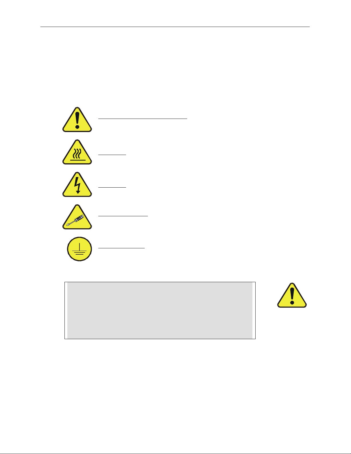
SAFETY MESSAGES
Your safety and the safety of others is very important. We have provided many important safety messages in
this manual. Please read these messages carefully.
A safety message alerts you to potential hazards that could hurt you or others. Each safety message is
associated with a safety alert symbol. These symbols are found in the manual and inside the instrument. The
definition of these symbols is described below:
GENERAL WARNING/CAUTION: Refer to the instructions for details on the
specific danger.
CAUTION: Hot Surface Warning
CAUTION: Electrical Shock Hazard
Technician Symbol: All operations marked with this symbol are to be performed
by qualified maintenance personnel only.
Electrical Ground: This symbol inside the instrument marks the central safety
grounding point for the instrument.
CAUTION
The analyzer should only be used for the purpose
and in the manner described in this manual.
If you use the analyzer in a manner other than that for which
it was intended, unpredictable behavior could ensue with
possible hazardous consequences.
ii
Page 4

TELEDYNE Model 9110AH NOX Analyzer Operator Manual, 01620, Rev. F
TABLE OF CONTENTS
SAFETY MESSAGES..................................................................................II
TABLE OF CONTENTS.............................................................................III
LIST OF FIGURES................................................................................... VII
LIST OF TABLES ................................................................................... VIII
1 HOW TO USE THIS MANUAL...............................................................1-1
2 GETTING STARTED.............................................................................2-1
2.1 UNPACKING ...........................................................................................................................2-1
2.2 ELECTRICAL AND PNEUMATIC CONNECTIONS .........................................................................2-1
2.3 INITIAL OPERATION.................................................................................................................2-6
3 SPECIFICATIONS, WARRANTY...........................................................3-1
3.1 SPECIFICATIONS.....................................................................................................................3-1
3.2 WARRANTY............................................................................................................................3-2
4 THE M9110AH NOX ANALYZER ...........................................................4-1
4.1 PRINCIPLE OF OPERATION......................................................................................................4-1
4.2 OPERATION SUMMARY...........................................................................................................4-4
4.2.1 Sensor Module, Reaction Cell, Detector....................................................................4-4
4.2.2 Pneumatic Sensor Board.............................................................................................4-4
4.2.3 Computer Hardware and Software .............................................................................4-5
4.2.4 V/F Board......................................................................................................................4-5
4.2.5 Front Panel...................................................................................................................4-5
4.2.6 Power Supply Module...................................................................................................4-7
4.2.7 Pump, Valves, Pneumatic System...............................................................................4-7
4.2.8 Ozone Generator...................................................................................................... 4-10
4.2.9 NO2 - NO Converter ................................................................................................. 4-10
5 SOFTWARE FEATURES.......................................................................5-1
5.1 INDEX TO FRONT PANEL MENUS............................................................................................5-1
5.1.1 Sample Menu................................................................................................................5-4
5.1.2 Set-Up Menu................................................................................................................5-5
5.2 SAMPLE MODE.......................................................................................................................5-9
5.2.1 Test Functions..............................................................................................................5-9
5.2.2 CAL, CALS, CALZ, Calibration Functions............................................................... 5-13
iii
Page 5

TELEDYNE Model 9110AH NOX Analyzer Operator Manual, 01620, Rev. F
5.3 SET-UP MODE ...................................................................................................................5-15
5.3.1 Configuration Information (CFG) ............................................................................. 5-15
5.3.2 Automatic Calibration (AutoCal)............................................................................... 5-15
5.3.3 Data Acquisition System (DAS) ............................................................................... 5-16
5.3.4 Range Menu.............................................................................................................. 5-18
5.3.5 Password Enable ......................................................................................................5-21
5.3.6 Time of Day Clock.....................................................................................................5-21
5.3.7 Diagnostic Mode ....................................................................................................... 5-21
5.3.8 Communications Menu............................................................................................. 5-21
5.3.9 Variables Menu (VARS) ...........................................................................................5-22
5.4 M9110AH OPERATING MODES.......................................................................................... 5-22
5.4.1 NO/NOx/NO2 Switching Mode ..................................................................................5-23
5.4.2 NOx Only Mode.......................................................................................................... 5-24
5.4.3 NO Only Mode........................................................................................................... 5-24
5.5 4-20 MA CURRENT LOOP................................................................................................... 5-24
5.6 STATUS OUTPUT................................................................................................................ 5-25
5.7 RS-232 INTERFACE........................................................................................................... 5-25
5.7.1 Setting up the RS-232 Interface............................................................................... 5-26
5.7.2 Command Summary..................................................................................................5-29
5.7.3 TEST Commands and Messages............................................................................ 5-33
5.7.4 WARNING Commands and Messages................................................................... 5-34
5.7.5 CALIBRATION Commands and Messages............................................................ 5-35
5.7.6 DIAGNOSTIC Commands and Messages.............................................................. 5-36
5.7.7 DAS Commands and Messages.............................................................................. 5-37
5.7.8 VARIABLES Commands and Messages................................................................. 5-39
6 OPTIONAL HARDWARE AND SOFTWARE..........................................6-1
6.1 RACK MOUNT OPTIONS.........................................................................................................6-1
6.2 ZERO/SPAN VALVES OPTION..................................................................................................6-2
6.2.1 Autocal - Setup Zero/Span Valves..............................................................................6-2
6.3 ISOLATED 4-20 MA CURRENT LOOP OPTION.........................................................................6-4
6.4 MOLYBDENUM CONVERTER OPTION......................................................................................6-5
6.5 EXTERNAL DESICCANT CANISTER OPTION.............................................................................6-5
6.6 ALTERNATE BYPASS FLOW ORIFICE OPTION..........................................................................6-5
6.7 EXTERNAL CONVERTER OPTION............................................................................................6-5
7 CALIBRATION AND ZERO/SPAN CHECKS.........................................7-1
7.1 MANUAL ZERO/SPAN CHECK OR CAL WITH ZERO/SPAN GAS IN THE SAMPLE PORT ...............7-3
7.2 MANUAL ZERO/SPAN CHECK WITH ZERO/SPAN VALVES OPTION ............................................7-6
7.3 DYNAMIC ZERO/SPAN CALIBRATION USING AUTOCAL ............................................................7-7
7.4 USE OF ZERO/SPAN VALVES WITH REMOTE CONTACT CLOSURE...........................................7-8
7.5 NO ONLY MODE CALIBRATION ..............................................................................................7-9
7.6 NO
ONLY MODE CALIBRATION .............................................................................................7-9
X
iv
Page 6

TELEDYNE Model 9110AH NOX Analyzer Operator Manual, 01620, Rev. F
7.7 CALIBRATION REQUIREMENTS FOR AUTORANGE OR REMOTE RANGE....................................7-9
7.8 CALIBRATION REQUIREMENTS FOR INDEPENDENT RANGE................................................... 7-10
7.9 CALIBRATION QUALITY ........................................................................................................ 7-10
7.10 CONVERTER EFFICIENCY COMPENSATION ........................................................................7-11
7.11 RECOMMENDATIONS FOR CEM APPLICATIONS ................................................................. 7-12
7.11.1 Calibration Gasses................................................................................................. 7-12
7.11.2 Calibration Frequency.............................................................................................7-13
7.11.3 Converter Efficiency............................................................................................... 7-13
8 MAINTENANCE ....................................................................................8-1
8.1 MAINTENANCE SCHEDULE......................................................................................................8-1
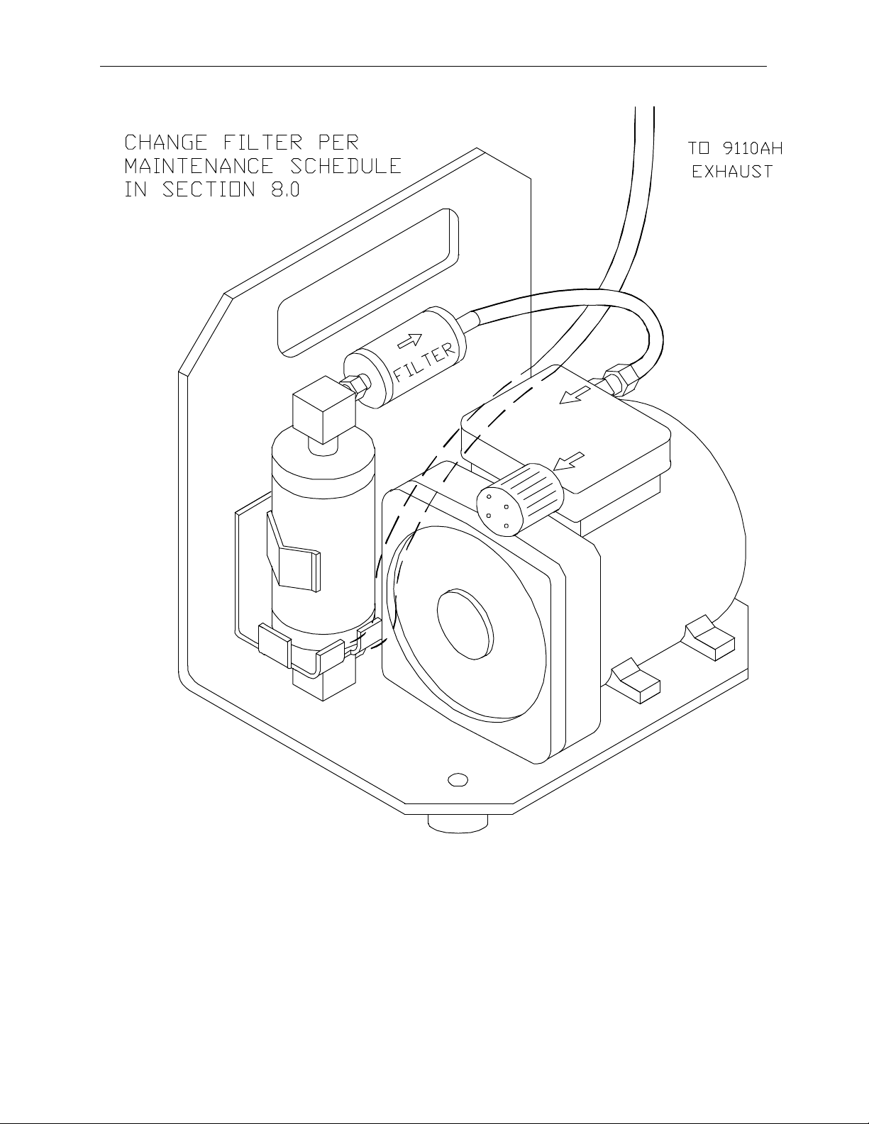
8.2 REPLACING THE SAMPLE PARTICULATE FILTER ......................................................................8-2
8.3 REPLACING THE CONVERTER.................................................................................................8-4
8.4 CLEANING THE REACTION CELL .............................................................................................8-6
8.5 PNEUMATIC LINE INSPECTION ............................................................................................. 8-10
8.6 LEAK CHECK PROCEDURE .................................................................................................. 8-13
8.7 LIGHT LEAK CHECK PROCEDURE........................................................................................ 8-13
8.8 PROM REPLACEMENT PROCEDURE.....................................................................................8-14
9 TROUBLESHOOTING AND ADJUSTMENTS .......................................9-1
9.1 OPERATION VERIFICATION - DIAGNOSTIC TECHNIQUES...........................................................9-3
9.1.1 Fault Diagnosis with TEST Variables..........................................................................9-3
9.1.2 Fault Diagnosis with WARNING Messages...............................................................9-8
9.1.3 Fault Diagnosis using DIAGNOSTIC Mode ............................................................9-10
9.1.4 M9110AH Internal Variables.................................................................................... 9-17
9.1.5 Test Channel Analog Output..................................................................................... 9-19
9.1.6 Factory Calibration Procedure................................................................................. 9-20
9.2 PERFORMANCE PROBLEMS................................................................................................. 9-24
9.2.1 AC Power Check....................................................................................................... 9-24
9.2.2 Flow Check................................................................................................................ 9-25
9.2.3 No Response to Sample Gas .................................................................................. 9-25
9.2.4 Negative Output......................................................................................................... 9-26
9.2.5 Excessive Noise....................................................................................................... 9-26
9.2.6 Unstable Span........................................................................................................... 9-27
9.2.7 Unstable Zero............................................................................................................ 9-28
9.2.8 Inability to Span......................................................................................................... 9-28
9.2.9 Inability to Zero.......................................................................................................... 9-28
9.2.10 Non-Linear Response............................................................................................ 9-29
9.2.11 Slow Response....................................................................................................... 9-30
9.2.12 Analog Output Doesn't Agree With Display Concentration.................................. 9-30
9.3 SUBSYSTEM TROUBLESHOOTING AND ADJUSTMENTS......................................................... 9-31
9.3.1 Computer, Display, Keyboard................................................................................... 9-31
9.3.2 RS-232 Communications ......................................................................................... 9-34
v
Page 7

TELEDYNE Model 9110AH NOX Analyzer Operator Manual, 01620, Rev. F
9.3.3 Voltage/Frequency (V/F) Board............................................................................... 9-37
9.3.4 Status/Temp Board................................................................................................... 9-43
9.3.5 Power Supply Module................................................................................................ 9-45
9.3.6 Ozone Generator...................................................................................................... 9-49
9.3.7 Flow/Pressure Sensor.............................................................................................. 9-53
9.3.8 NOx Sensor Module .................................................................................................. 9-58
9.3.9 Z/S Valves .................................................................................................................9-63
9.3.10 Pneumatic System.................................................................................................. 9-64
10 M9110AH SPARE PARTS LIST.........................................................10-1
APPENDIX A ELECTRICAL SCHEMATICS............................................ A-1
vi
Page 8

TELEDYNE Model 9110AH NOX Analyzer Operator Manual, 01620, Rev. F
LIST OF FIGURES
FIGURE 2-1: REMOVAL OF SHIPPING SCREWS & CHECK FOR CORRECT POWER.............................2-3
FIGURE 2-2: REAR PANEL...............................................................................................................2-4
FIGURE 2-3: INLET AND EXHAUST VENTING RECOMMENDATIONS....................................................2-5
FIGURE 2-4: FRONT PANEL..........................................................................................................2-10
FIGURE 2-5: ASSEMBLY LAYOUT.................................................................................................. 2-12
FIGURE 4-1: BLOCK DIAGRAM.........................................................................................................4-3
FIGURE 4-2: EXTERNAL PUMP PACK...............................................................................................4-9
FIGURE 5-1: SAMPLE MENU TREE ..................................................................................................5-2
FIGURE 5-2: SETUP MENU TREE ....................................................................................................5-3
FIGURE 8-1: REPLACING THE PARTICULATE FILTER ........................................................................8-3
FIGURE 8-2: CONVERTER ASSEMBLY..............................................................................................8-5
FIGURE 8-3: REACTION CELL ASSEMBLY ........................................................................................8-8
FIGURE 8-4: SAMPLE/BYPASS FLOW CONTROL ASSEMBLY.............................................................8-9
FIGURE 8-5: PNEUMATIC DIAGRAM............................................................................................... 8-11
FIGURE 8-6: PNEUMATIC DIAGRAM WITH ZERO/SPAN VALVES...................................................... 8-12
FIGURE 9-1: SPAN CALIBRATION VOLTAGE................................................................................... 9-23
FIGURE 9-2: CPU BOARD JUMPER SETTINGS ............................................................................. 9-33
FIGURE 9-3: RS-232 PIN ASSIGNMENTS..................................................................................... 9-35
FIGURE 9-4: V/F BOARD JUMPER SETTINGS................................................................................ 9-42
FIGURE 9-5: POWER SUPPLY MODULE LAYOUT........................................................................... 9-47
FIGURE 9-6: ELECTRICAL BLOCK DIAGRAM .................................................................................. 9-48
FIGURE 9-7: OZONE GENERATOR SUBSYSTEM............................................................................ 9-52
FIGURE 9-8: FLOW/PRESSURE SENSOR ...................................................................................... 9-55
FIGURE 9-9: NO
FIGURE 9-10: NO
FIGURE 9-11: PMT COOLER SUBSYSTEM ................................................................................... 9-60
FIGURE 9-12: HIGH VOLTAGE POWER SUPPLY ............................................................................ 9-62
SENSOR MODULE ............................................................................................ 9-56
X
SENSOR MODULE.......................................................................................... 9-57
X
vii
Page 9

TELEDYNE Model 9110AH NOX Analyzer Operator Manual, 01620, Rev. F
LIST OF TABLES
TABLE 2-1: FINAL TEST AND CALIBRATION VALUES....................................................................... 2-13
TABLE 2-1: FINAL TEST AND CALIBRATION VALUES (CONTINUED)................................................. 2-14
TABLE 4-1: SAMPLING MODES OF THE M9110AH ..........................................................................4-1
TABLE 4-2: FRONT PANEL STATUS LED'S......................................................................................4-6
TABLE 4-3: OZONE GENERATOR START-UP TIMING ..................................................................... 4-10
TABLE 5-1: M9110AH SAMPLE MENU STRUCTURE .......................................................................5-4
TABLE 5-2: M9110AH SETUP MENU .............................................................................................5-5
TABLE 5-2: M9110AH SETUP MENU (CONTINUED).......................................................................5-6
TABLE 5-3: M9110AH SETUP MENU .............................................................................................5-7
TABLE 5-4: M9110AH SETUP MENU .............................................................................................5-8
TABLE 5-5: DAS DATA CHANNEL EDITING................................................................................... 5-17
TABLE 5-6: CALIBRATE, SETUP PASSWORDS............................................................................... 5-21
TABLE 5-7: M9110AH OPERATING MODES................................................................................. 5-23
TABLE 5-8: STATUS OUTPUT PIN ASSIGNMENTS......................................................................... 5-25
TABLE 5-9: RS-232 PORT SETUP - FRONT PANEL......................................................................5-26
TABLE 5-10: RS-232 SWITCHING FROM TERMINAL MODE TO COMPUTER MODE........................ 5-28
TABLE 5-11: RS-232 TERMINAL MODE EDITING KEYS.................................................................5-28
TABLE 5-12: RS-232 COMMAND SUMMARY ................................................................................ 5-30
TABLE 5-13: RS-232 COMMAND SUMMARY ................................................................................ 5-31
TABLE 5-14: RS-232 INTERFACE COMMAND TYPES....................................................................5-32
TABLE 5-15: RS-232 TEST MESSAGES....................................................................................... 5-33
TABLE 5-16: RS-232 WARNING MESSAGES................................................................................ 5-34
TABLE 5-17: RS-232 CALIBRATION MESSAGES........................................................................... 5-35
TABLE 5-18: RS-232 CALIBRATION COMMANDS.......................................................................... 5-36
TABLE 5-19: RS-232 DIAGNOSTIC COMMAND SUMMARY ............................................................5-37
TABLE 6-1: ZERO/SPAN VALVE OPERATION ....................................................................................6-2
TABLE 6-2: SETUP AUTOMATIC ZERO/SPAN CHECKING OR CALIBRATION........................................6-3
TABLE 6-3: ACTION OF MODE FIELD IN AUTOCAL..........................................................................6-4
TABLE 7-1: TYPES OF ZERO/SPAN CHECK AND CALIBRATION..........................................................7-2
TABLE 7-2: MANUAL ZERO CALIBRATION PROCEDURE - ZERO GAS THRU SAMPLE PORT................7-3
TABLE 7-3: ENTER EXPECTED SPAN GAS CONCENTRATIONS PROCEDURE.....................................7-4
TABLE 7-4: MANUAL SPAN CALIBRATION PROCEDURE - SPAN GAS THRU SAMPLE PORT.................7-5
TABLE 7-5: MANUAL ZERO CHECK PROCEDURE - Z/S VALVES........................................................7-6
TABLE 7-6: MANUAL SPAN CHECK PROCEDURE - Z/S VALVES........................................................7-7
TABLE 7-7: Z/S VALVE MODES WITH REMOTE CONTACT CLOSURE................................................7-8
TABLE 7-8: CALIBRATION REQUIREMENTS FOR AUTORANGE OR REMOTE RANGE........................ 7-10
TABLE 7-9: CALIBRATION QUALITY CHECK ................................................................................... 7-11
TABLE 7-10: CONVERTER EFFICIENCY - AUTOMATIC CALCULATION .............................................7-12
TABLE 8-1: PREVENTATIVE MAINTENANCE SCHEDULE.....................................................................8-1
viii
Page 10

TELEDYNE Model 9110AH NOX Analyzer Operator Manual, 01620, Rev. F
TABLE 9-1: TEST FUNCTIONS.........................................................................................................9-4
TABLE 9-1: TEST FUNCTIONS (CONTINUED)...................................................................................9-5
TABLE 9-1: TEST FUNCTIONS (CONTINUED)...................................................................................9-6
TABLE 9-1: TEST FUNCTIONS (CONTINUED)...................................................................................9-7
TABLE 9-2: FRONT PANEL WARNING MESSAGES ............................................................................9-9
TABLE 9-2: FRONT PANEL WARNING MESSAGES (CONTINUED)................................................... 9-10
TABLE 9-3: SUMMARY OF DIAGNOSTIC MODES ............................................................................ 9-11
TABLE 9-4: DIAGNOSTIC MODE - SIGNAL I/O................................................................................ 9-12
TABLE 9-4: DIAGNOSTIC MODE - SIGNAL I/O (CONTINUED).......................................................... 9-13
TABLE 9-4: DIAGNOSTIC MODE - SIGNAL I/O (CONTINUED).......................................................... 9-14
TABLE 9-4: DIAGNOSTIC MODE - SIGNAL I/O (CONTINUED).......................................................... 9-15
TABLE 9-5: MODEL 9110AH VARIABLES...................................................................................... 9-18
TABLE 9-6: TEST CHANNEL READINGS.........................................................................................9-19
TABLE 9-6: TEST CHANNEL READINGS (CONTINUED)...................................................................9-20
TABLE 9-7: MOTHERBOARD JUMPER SETTINGS........................................................................... 9-39
TABLE 9-1: V/F BOARD SWITCH SETTINGS.................................................................................. 9-39
TABLE 9-8: POWER SUPPLY MODULE SUBASSEMBLIES................................................................ 9-46
TABLE 9-9: POWER SUPPLY MODULE LED OPERATION............................................................... 9-49
TABLE 9-10: OZONE GENERATOR CONTROL CONDITIONS........................................................... 9-50
TABLE 10-1: TELEDYNE M9110AH SPARE PARTS LIST........................................................... 10-1
TABLE 10-1: TELEDYNE M9110AH SPARE PARTS LIST (CONTINUED).....................................10-2
TABLE 10-1: TELEDYNE M9110AH SPARE PARTS LIST (CONTINUED).....................................10-3
TABLE 10-2: TELEDYNE MODEL 9110AH EXPENDABLES KIT ................................................ 10-4
TABLE 10-3: TELEDYNE MODEL 9110AH LEVEL 1 SPARES KIT WITH MINI-HICON CONVERTER
............................................................................................................................................. 10-5
TABLE 10-4: TELEDYNE MODEL 9110AH LEVEL 1 SPARES KIT WITH MOLYBDENUM
CONVERTER.......................................................................................................................... 10-6
TABLE A-1: ELECTRICAL SCHEMATICS ........................................................................................... A-1
ix
Page 11

TELEDYNE Model 9110AH NOX Analyzer Operator Manual, 01620, Rev. F
INTENTIONALLY BLANK
x
Page 12

TELEDYNE Model 9110AH NOX Analyzer Operator Manual, 01620, Rev. F
1 HOW TO USE THIS MANUAL
The Model 9110AH has been designed to produce accurate data, be serviceable, reliable and
easy to use. The M9110AH's microprocessor continually checks operating parameters such as
temperature, flow, and critical voltages. The instruments design uses top mounted, modular
components with captive screws to facilitate repair and ease of access. If you encounter any
difficulty refer to the Troubleshooting Section 9 - General Hints.
We recognize that the need for information from this manual changes as time passes. When the
instrument first arrives, it is necessary to get it up and running quickly and verify its correct
operation. As time passes, more detailed information is often required on special
configurations, calibration alternatives and other operational details. Finally there is the need
for periodic maintenance and to quickly troubleshoot problems to assure maximum reliability
and data integrity.
To address these needs, we have created three indexes to the information inside. They are:
Table of Contents:
Outlines the contents of the manual in the order the information is presented. This is a good
overview of the topics covered in the manual. There is also a list of Tables and a list of Figures.
Index to M9110AH Front Panel Menus:
The Menu Index briefly describes the front panel menus and refers you to other sections of the
manual that have a detailed explanation of each menu selection.
Troubleshooting Section 9:
The Troubleshooting Section allows you to diagnose and repair the instrument based on
variables in the TEST menu, the results of DIAGNOSTIC tests, and performance faults such as
excessive noise or drift. The troubleshooting section also explains the operation, adjustment,
diagnosis and testing of each instrument subsystem.
If you are unpacking the instrument for the first time, please refer to Getting Started in
Section 2.
1-1
Page 13

TELEDYNE Model 9110AH NOX Analyzer Operator Manual, 01620, Rev. F
INTENTIONALLY BLANK
1-2
Page 14

TELEDYNE Model 9110AH NOX Analyzer Operator Manual, 01620, Rev. F
2 GETTING STARTED
2.1 Unpacking
CAUTION
Your safety and the safety of others is very important. We
have provided many important safety messages in this manual.
Please read these messages carefully.
To avoid personal injury, always use two persons to
lift and carry the Model 9110AH.
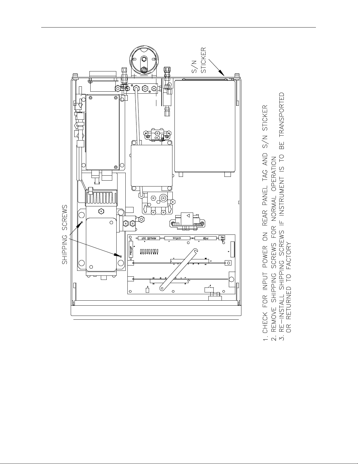
1. Before operation it is necessary to remove the shipping hold-down screws. Remove the
instrument cover, then remove 2 screws as shown in Figure 2-1.
2. Also check for internal shipping damage, and generally inspect the interior of the instrument
to make sure all circuit boards and other components are in good shape.
3. Please check the voltage and frequency label on the serial number tag on the rear panel.
Compare that to your local power before plugging in the Instrument.
2.2 Electrical and Pneumatic Connections
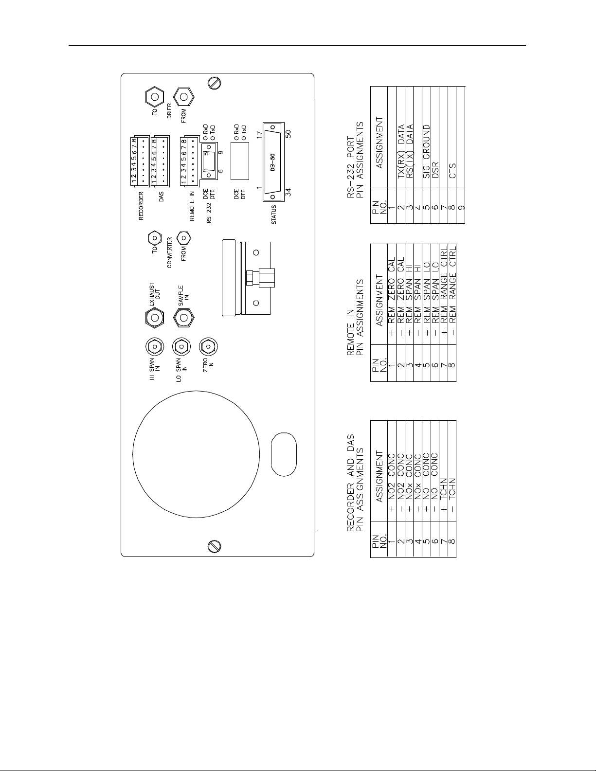
1. Refer to Figure 2-2 to locate the rear panel electrical and pneumatic connections.
2. Attach the pump to the “Exhaust Out” port on the instrument rear panel. The exhaust from
the pump should also be vented to atmospheric pressure.
3. Attach the sample inlet line to the sample inlet port. For initial testing, sample gas can be
calibration gas or stack gas. The pressure of the sample gas at the inlet port should be at
ambient pressure and constant. See Figure 2-3.
4. If desired, attach the analog output connections to a strip chart recorder and/or datalogger.
Refer to Figure 9-4 - Analog Output Voltage Ranges - for switch settings. Factory default
setting is 0-5 VDC.
5. Connect the power cord to the correct voltage line, then turn to Section 2.3 Initial
Operation.
2-1
Page 15
TELEDYNE Model 9110AH NOX Analyzer Operator Manual, 01620, Rev. F
electrical subassemblies.
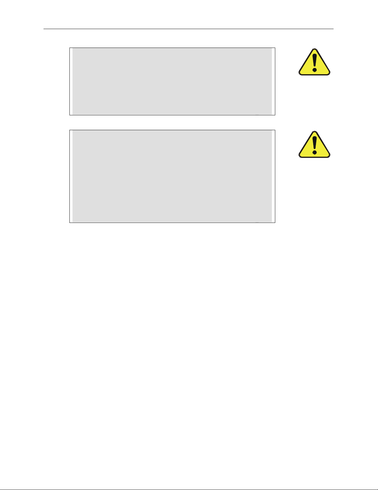
WARNING
Analyzer Exhaust – O3 Scrubber – Pump Pack
Danger – Analyzer exhaust contains ozone.
Ozone scrubber must always be present between
analyzer exhaust and pump.
Vent pump exhaust to well ventilated area at atmosphere
pressure FIRE or EXPLOSION HAZARD.
WARNING
Lethal voltages present inside case.
Do not operate with cover off during normal operation.
Before operation check for correct
input voltage and frequency.
Do not operate without proper chassis grounding.
Do not defeat the ground wire on power plug.
Turn off analyzer power before disconnecting
2-2
Page 16
TELEDYNE Model 9110AH NOX Analyzer Operator Manual, 01620, Rev. F
Figure 2-1: Removal of Shipping Screws & Check for Correct Power
2-3
Page 17
TELEDYNE Model 9110AH NOX Analyzer Operator Manual, 01620, Rev. F
Figure 2-2: Rear Panel
2-4
Page 18
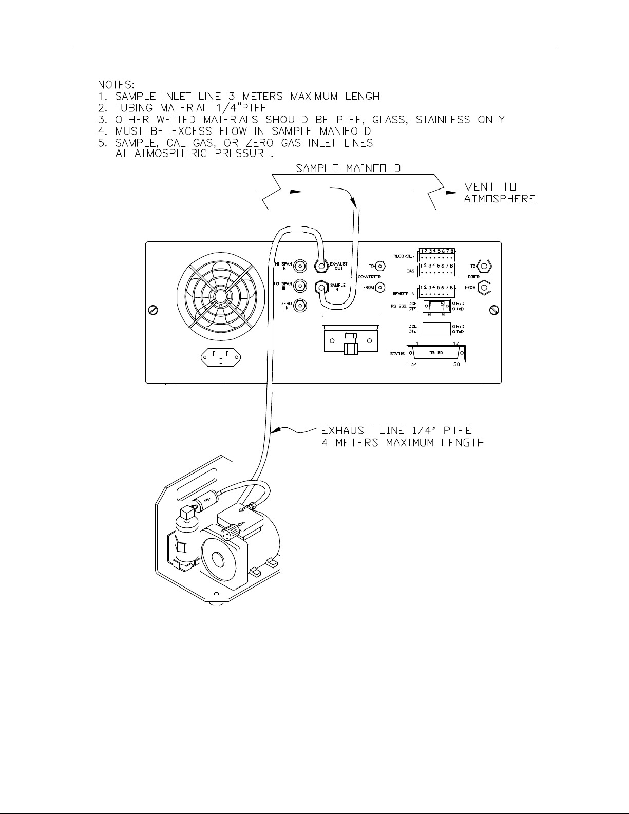
TELEDYNE Model 9110AH NOX Analyzer Operator Manual, 01620, Rev. F
Figure 2-3: Inlet and Exhaust Venting Recommendations
2-5
Page 19

TELEDYNE Model 9110AH NOX Analyzer Operator Manual, 01620, Rev. F
2.3 Initial Operation
1. Turn on the instrument power.
2. The display should immediately light, showing the computer’s memory configuration, then
the instrument type - M9110AH. If you are unfamiliar with the M9110AH, we recommend
that you read the overview Section 4 before proceeding. A diagram of the software menu
trees is in Figure 5-1 and Figure 5-2.
3. The M9110AH requires about 30 minutes for all internal components to come to
temperature. During this time the ozone generator power is OFF until the membrane dryer
has time to purge itself, therefore there will be no response from the instrument, even if
span gas is coming in the sample port. Many warning conditions are not displayed during
this time, even though temperatures and other conditions are out of specification. All
warning messages are enabled after 30 minutes of operation.
4. While waiting for instrument temperatures to stabilize, you can check for correct operation
by using some of the M9110AH's diagnostic and test features.
5. Examine the TEST functions by comparing the values listed in Table 2-1 to those in the
display. Remember that as the instrument warms up the values may not have reached their
final values yet. If you would like to know more about the meaning and utility of each
TEST function refer to Table 9-1. Also, now is a good time to verify that the instrument was
shipped with the options you ordered. Table 2-1 also contains the list of options. Section 6
covers setting up the options.
6. Electric Test and Optic Test both generate simulated signals in the M9110AH.
A. Electric Test checks the electronics of the PMT signal path. To operate Electric Test from
the front panel:
1) Scroll the TEST function to PMT.
2) Press SETUP-MORE-DIAG, then press ENTR to accept the default password. Scroll
to Electric Test and press ENTR to turn it on. Instrument responses should come to
the values indicated in Table 2-1. To turn off this test press EXIT. For more
information on the circuitry being tested refer to the Troubleshooting Section 9.1.3.2.
B. Optic Test is an "end to end" test of the analyzer HVPS-PMT-detector-electronics-
computer. It simulates a signal by turning on a LED in the Sensor Module. To operate
Optic Test from the front panel:
1) Scroll the TEST function to PMT.
2) Press SETUP-MORE-DIAG, then press ENTR to accept the default password. Scroll
to Optic Test and press ENTR to turn on optic test. Instrument response should come
up to the values indicated in Table 2-1. To turn off this test press EXIT. To return to
the SAMPLE mode press EXIT until SAMPLE is displayed in the upper left display.
For more information about OT operation see Section 9.1.3.3.
2-6
Page 20

TELEDYNE Model 9110AH NOX Analyzer Operator Manual, 01620, Rev. F
7. When the instrument is warmed up, re-check the TEST functions against Table 2-1. All of
the readings should compare closely with those in the table. If they do not see Section 9.1.1.
The next task is to calibrate the analyzer. There are several ways to do a calibration, they are
summarized in Table 7-1. For a preliminary checkout we recommend calibration with span
gas coming in through the sample port. The procedure is:
Step 1 - Set the range, then enter the expected NOx and NO span gas concentrations:
Step Number Action Comment
1. Press
CAL-CONC-NOX
2. Press ENTR ENTR stores the expected NOx span value. The internal
3. Press
CAL-CONC-NO
4. Press ENTR ENTR stores the expected NO span value. The internal
5. Press EXIT Returns instrument to SAMPLE mode.
6. Press
SETUP-RNGEMODE-SNGL
7. Press
SETUP-RNGESET
This key sequence causes the M9110AH to prompt for the
expected span concentration. Enter the span value by pressing
the key under each digit until the expected value is set.
formulas are adjusted to compute this number when span gas
concentration is input into the instrument.
In the same CAL-CONC sub menu press the NO button and
enter the expected NO span value. As before this value will be
used in the internal formulas to compute the NO concentration
value.
formulas are adjusted to compute this number when span gas
concentration is input into the instrument.
If necessary, you may want to change ranges. Normally the
instrument is shipped in single range mode set at 100 ppm. We
recommend doing the initial checkout on the 100 ppm range.
After SETUP-RNGE-SET, enter 100 and press ENTR. The
instrument will now be in the 100 ppm range.
2-7
Page 21

TELEDYNE Model 9110AH NOX Analyzer Operator Manual, 01620, Rev. F
Step 2 - Calibrate the instrument:
Zero/Span Calibration Procedure
Step Number Action Comment
1. Input Zero gas Allow Zero gas to enter the sample port on the rear of the
instrument.
2. Press CAL The M9110AH enters the calibrate mode from sample mode.
3. Wait 10 min Wait for reading to stabilize at the zero value. If you wait less
than 10 minutes the final zero value may drift.
4. Press ZERO The ZERO button will be displayed.
5. Press ENTR Pressing ENTR actually changes the equations and zeros the
instrument.
6. Press EXIT, input
Span gas
7. Wait 10 min Wait for reading to stabilize at the span value.
8. Press SPAN The SPAN button should be displayed. If there is no SPAN
9. Press ENTR Pressing ENTR actually changes the equations so that the
10. Press EXIT Pressing EXIT returns the instrument to SAMPLE mode.
M9110AH returns to the CAL menu. Now switch gas streams
to span gas.
button check the Troubleshooting Section 9.2.8 for
instructions on how to proceed. In certain circumstances at
low span gas concentrations both the ZERO and SPAN
buttons will appear.
concentration displayed is the same as the expected span
concentration you entered above, thus spanning the instrument.
2-8
Page 22

TELEDYNE Model 9110AH NOX Analyzer Operator Manual, 01620, Rev. F
Step 3 - Review Quality of calibration:
Calibration Quality Check Procedure
Step Number Action Comment
1. Scroll the TEST
function menu until
the NOx SLOPE is
displayed.
2. Scroll the TEST
function menu until
the NO SLOPE is
displayed.
4. Scroll the TEST
function menu until
the NOx OFFS is
displayed.
5. Scroll the TEST
function menu until
the NO OFFS is
displayed.
The SLOPE value for NOx should be 1.0 0.3. If the value is
not in this range, check Section 7.1 or 9. If the SLOPE value is
in the acceptable range the instrument will perform optimally.
The SLOPE value for NO should be 1.0 0.3. If the value is
not in this range, check Section 7.1 or 9. If the SLOPE is in the
acceptable range the instrument will perform optimally.
NOTE:
The NO and NOx slopes should be equal within 0.3.
The M9110AH will display the OFFSET parameter for the
NOx equation. This number should be near zero. A value of
0.0 50 indicates calibration in the optimal range. If the
OFFSET value is outside this range, check Section 7.1 or 9.1
for procedures to correct the OFFSET value to near zero.
The Instrument will now display the NO OFFSET value. It
should also have a value near zero (0.0 50).
Step 4 - The M9110AH is now ready to measure sample gas.
2-9
Page 23
TELEDYNE Model 9110AH NOX Analyzer Operator Manual, 01620, Rev. F
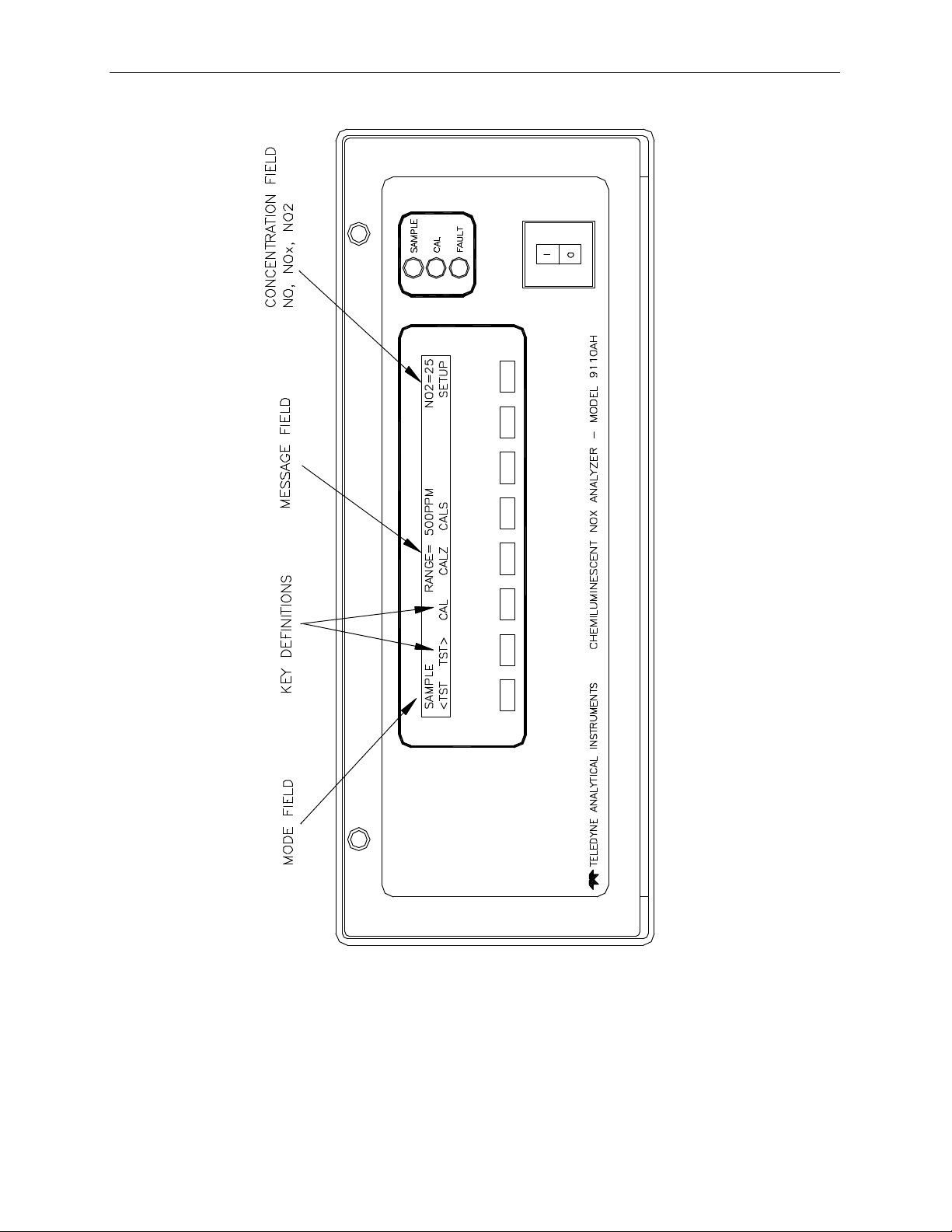
Figure 2-4: Front Panel
2-9
Page 24

TELEDYNE Model 9110AH NOX Analyzer Operator Manual, 01620, Rev. F
2-11
Page 25
TELEDYNE Model 9110AH NOX Analyzer Operator Manual, 01620, Rev. F
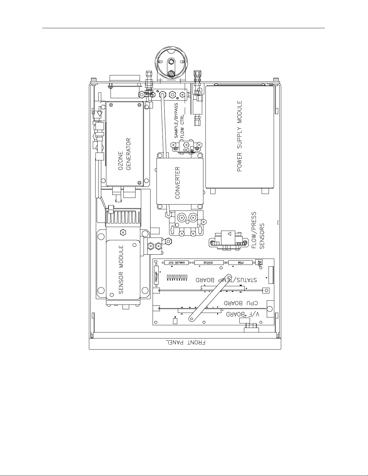
Figure 2-5: Assembly Layout
2-12
Page 26
TELEDYNE Model 9110AH NOX Analyzer Operator Manual, 01620, Rev. F
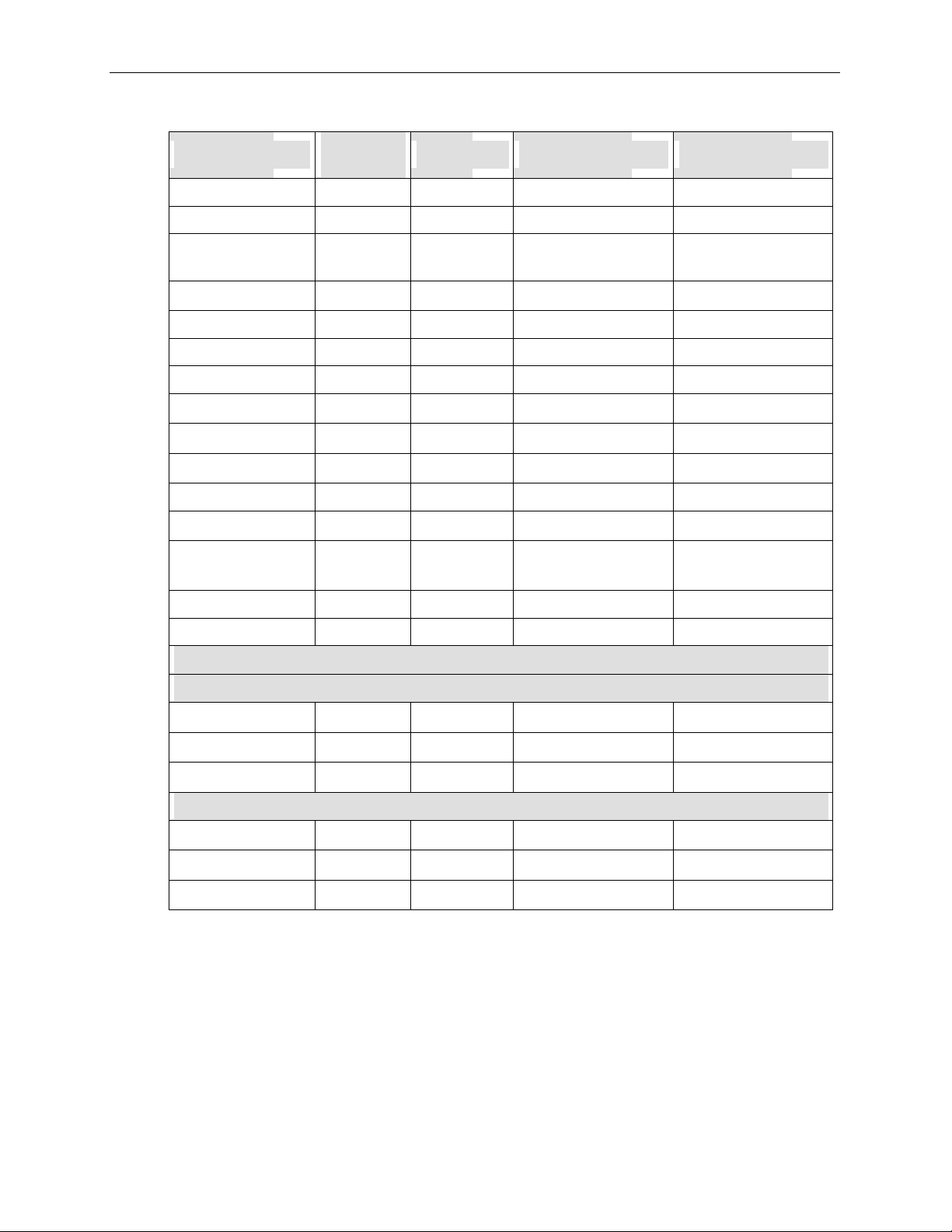
Table 2-1: Final Test and Calibration Values
TEST Values
RANGE ppm 5-5000 5.3.4
NOISE ppm 0.0 - 0.2 9.1.1, Table 9-1, 9.2.5
SAMP FLW cc/min 300 50 (Default)
OZONE FL cc/min 250 15 9.3.6
PMT mV 0-5000 9.3.8
AUTOZERO mV -10 to +50 4.1
HVPS V 400 - 700 constant 9.3.8.5
DCPS mV 2500 200 9.3.5
RCELL TEMP
BLOCK TEMP
BOX TEMP
PMT TEMP
CONV TEMP
Observed
Value
Units Nominal Range Reference Section
9.3.7, Table 9-1
550 50 (Optional)
o
C 50 2 9.3.8.2
o
C 50 2 9.3.4.1
o
C 8-48 9.3.4.1
o
C 7 1 9.3.8.4
o
C 700 10 (Std)
315 5 (Moly)
9.3.4.1
RCEL PRES IN-Hg-A 2 - 10 constant 9.3.7
SAMP PRES IN-Hg-A 25 - 30 constant 9.3.7
Electric Test &Optic Test
Electric Test
PMT Volts mV 2000 200 9.1.3.2
NO Conc ppm 250 25 9.1.3.2
NOx Conc ppm 250 25 9.1.3.2
OPTIC TEST
PMT Volts mV 100 20 9.1.3.3
NO Conc ppm 12.5 2 9.1.3.3
NOx Conc ppm 12.5 2 9.1.3.3
(table continued)
2-13
Page 27

TELEDYNE Model 9110AH NOX Analyzer Operator Manual, 01620, Rev. F
Table 2-1: Final Test and Calibration Values (Continued)
Parameter
NO Span Conc ppm 0.5 - 5000 Table 7-3
NOx Span Conc ppm 0.5 - 5000 Table 7-3
NO Slope - 1.0 0.3 7.1, 7.9
NOx Slope - 1.0 0.3 7.1
NO Offset mV 25 7.1, 7.2
NOx Offset mV 25 7.1, 7.2
Conv Efficiency % 0.75 - 1.10 7.10, 5.2.2.6
Noise at Zero ppm 0.0 - 0.2 Table 9-1
Noise At Span ppm 0.1 - 0.5 Table 9-1
Sample Flow cc/min 50 20 9.3.7, Figure 9-8
Bypass Flow cc/min 250 (Std)
Ozone Flow cc/min 250 15 9.3.7, Figure 9-8
Factory Installed Options Option Installed
Observed
Value
Units Nominal Range Reference Section
Measured Flows
Figure 8-4
500 (Optional)
Power Voltage/Frequency
Rack Mount, w/ Slides
Rack Mount, w/ Ears Only
Rack Mount, External Pump w/o Slides
Stainless Zero/Span Valves
4-20 mA Current Loop Output, Isolated
Bypass flow 500 cc/min
Molybdenum Converter
Desiccant Canister - O3 generator
PROM # Serial #
Date Technician
2-14
Page 28

TELEDYNE Model 9110AH NOX Analyzer Operator Manual, 01620, Rev. F
INTENTIONALLY BLANK
2-15
Page 29

TELEDYNE Model 9110AH NOX Analyzer Operator Manual, 01620, Rev. F
3 SPECIFICATIONS, WARRANTY
3.1 Specifications
Operating Modes
Ranges In 1 ppm increments from 5 ppm to 5,000 ppm
Noise at zero 0.02 ppm RMS
Noise at span <0.2% of reading RMS above 20 ppm
Detection Limit(Note 1) 0.04 ppm RMS
Zero Drift (Note 2) <0.2% full scale/24 hours
Zero Drift (Note 2) <0.4% full scale/7 days
Span Drift (Note 2) <1% FS/24 hours
Lag Time
Switching Mode 20 sec (Note 3)
NO
mode
x
Response Time
Switching Mode 95% in < 40 sec (Note 3)
NO
mode
x
Sample Flow Rate 290 10 cc/min (Including bypass)
Linearity 1% of full scale
Precision 0.5% of reading
Temperature Range 5-40o C
Humidity 0-95% RH non-condensing
Temp Coefficient < 0.1% per o C
Voltage Coefficient < 0.1% per V
Dimensions HxWxD 7"x17"x23.6" (18 cm x 43 cm x 61 cm)
Weight, Analyzer 43 lbs (20 kg)
Weight, Pump Pack 16 lbs (7 kg)
Power, Analyzer 100 V~ 50/60 Hz, 120 V~ 60 Hz, 220 V~ 50 Hz, 240 V~ 50 Hz, 200 watts
Power, Analyzer
Power, Ext Pump 110 V~ 60 Hz, 220 V~ 50 Hz, 240 V~ 50 Hz, 295 watts
Power, Ext Pump
Environmental Installation Category (Over-voltage Category) II
Pollution Degree 2
Analog Resolution 1 part in 2048 of selected voltage or current range
Recorder Output 0-100 mV, 0-1, 5, 10v, bipolar
Current Loop Option 4-20ma isolated
Status 12 Status Outputs from opto-isolator
Measurement Units ppm, mg/m3
4
230 V~ 50 Hz, 2.5A
4
230 V~ 50 Hz, 2.5A
NO/NOx switching mode, NO only mode, NOx only mode
Single range, independent ranges or autoranging
4 sec (Note 3)
95% in < 10 sec (Note 3)
1. Defined as twice the zero noise level.
2. At constant temperature and voltage.
3. Lag & response times longer for external converter option.
4. Electrical ratings for CE Mark compliance.
3-1
Page 30

TELEDYNE Model 9110AH NOX Analyzer Operator Manual, 01620, Rev. F
3.2 Warranty
WARRANTY POLICY (02024c)
Prior to shipment, TELEDYNE equipment is thoroughly inspected and tested. Should
equipment failure occur, TELEDYNE assures its customers that prompt service and support
will be available.
COVERAGE
After the warranty period and throughout the equipment lifetime, TELEDYNE stands ready to
provide on-site or in-plant service at reasonable rates similar to those of other manufacturers in
the industry. All maintenance and the first level of field troubleshooting is to be performed by
the customer.
NON-TELEDYNE MANUFACTURED EQUIPMENT
Equipment provided but not manufactured by TELEDYNE is warranted and will be repaired to
the extent and according to the current terms and conditions of the respective equipment
manufacturers warranty.
GENERAL
TELEDYNE warrants each Product manufactured by TELEDYNE to be free from defects in
material and workmanship under normal use and service for a period of one year from the date
of delivery. All replacement parts and repairs are warranted for 90 days after the purchase.
If a Product fails to conform to its specifications within the warranty period, TELEDYNE shall
correct such defect by, in TELEDYNE's discretion, repairing or replacing such defective
Product or refunding the purchase price of such Product.
The warranties set forth in this section shall be of no force or effect with respect to any
Product: (i) that has been altered or subjected to misuse, negligence or accident, or (ii) that has
been used in any manner other than in accordance with the instruction provided by
TELEDYNE or (iii) not properly maintained.
THE WARRANTIES SET FORTH IN THIS SECTION AND THE REMEDIES
THEREFORE ARE EXCLUSIVE AND IN LIEU OF ANY IMPLIED WARRANTIES
OF MERCHANTABILITY, FITNESS FOR PARTICULAR PURPOSE OR OTHER
WARRANTY OF QUALITY, WHETHER EXPRESSED OR IMPLIED. THE
REMEDIES SET FORTH IN THIS SECTION ARE THE EXCLUSIVE REMEDIES
FOR BREACH OF ANY WARRANTY CONTAINED HEREIN. TELEDYNE SHALL
NOT BE LIABLE FOR ANY INCIDENTAL OR CONSEQUENTIAL DAMAGES
ARISING OUT OF OR RELATED TO THIS AGREEMENT OF TELEDYNE'S
PERFORMANCE HEREUNDER, WHETHER FOR BREACH OF WARRANTY OR
OTHERWISE.
3-2
Page 31

TELEDYNE Model 9110AH NOX Analyzer Operator Manual, 01620, Rev. F
TERMS AND CONDITIONS
All units or components returned to TELEDYNE should be properly packed for handling and
returned freight prepaid to the nearest designated Service Center. After the repair, the
equipment will be returned, freight prepaid.
3-3
Page 32

TELEDYNE Model 9110AH NOX Analyzer Operator Manual, 01620, Rev. F
INTENTIONALLY BLANK
3-4
Page 33

TELEDYNE Model 9110AH NOX Analyzer Operator Manual, 01620, Rev. F
4 THE M9110AH NOX ANALYZER
4.1 Principle of Operation
The TELEDYNE Model 9110AH Analyzer is designed to measure the concentration of nitric
oxide [NO], total oxides of nitrogen [NOx] and, by calculation, nitrogen dioxide [NO2]. With
the proper setup, it can operate in any of three sampling modes.
Table 4-1: Sampling Modes of the M9110AH
Mode Description
NO/NOX switching mode Converter is switched, measures NO, NOx , and NO2
NO only mode Converter is switched out of sample stream. Nitric Oxide is only gas
measured.
NOx only mode Converter is switched into the sample stream, NOx is only gas
measured.
Regardless of which sampling mode the instrument is operating in, the signal from the
M9110AH comes from the light emitted from the chemiluminescent gas phase reaction of nitric
oxide [NO] and ozone [O3] as follows:
223 O*NOONO +¾ ®¾+
hvNO*NO 22 +¾ ®¾
The reaction of NO with ozone results in electronically excited NO2 molecules as shown in the
first equation above. The excited NO2 molecules release their excess energy by emitting a
photon and dropping to a lower energy level as shown in the second equation. It has been
shown that the light intensity produced is directly proportional to the [NO] concentration
present.
In the NO mode, the sample gas is routed directly into the reaction cell. Any NO gas present
reacts with ozone, producing light as described above.
In the NOx mode, the sample gas is routed through a NO2 to NO converter, and any NO2
present is reduced to NO. The NO initially present remains as NO, therefore the signal is the
sum of NO and NO2 present in the sample gas stream.
4-1
Page 34

TELEDYNE Model 9110AH NOX Analyzer Operator Manual, 01620, Rev. F
In the NO/ NOx switching mode the Analyzer samples the gas stream and measures [NO]
concentration by digitizing the signal from the Analyzer's photomultiplier tube (PMT). The
concentration is measured and stored internally. The valve is then switched, routing the sample
gas through the converter, the signal measured is the NOx concentration which is also stored in
the computer.
The [NO2] component is calculated by subtracting [NOx] - [NO] = [NO2] using the built-in
computer. The three results [NO], [NOx], and [NO2] are then further processed and stored by
the computer yielding several instantaneous and long term averages for all three components.
Periodically, the AutoZero valve switches allowing the analyzer to read zero background. The
AutoZero readings are subtracted from all of the other readings. This improves zero baseline
stability.
4-2
Page 35

TELEDYNE Model 9110AH NOX Analyzer Operator Manual, 01620, Rev. F
Figure 4-1: Block Diagram
4-3
Page 36

TELEDYNE Model 9110AH NOX Analyzer Operator Manual, 01620, Rev. F
4.2 Operation Summary
4.2.1 Sensor Module, Reaction Cell, Detector
The sensor module is where light from the chemilumenescent reaction is generated and
detected. It is the most complicated and critical sub-assembly in the entire analyzer. It consists
of the following assemblies and functions:
1. The reaction cell and ozone flow control module
2. Reaction cell heater/thermistor
3. PMT and High Voltage Power Supply
4. PMT cooler/cold block/heatsink/fan
5. Preamp assembly:
A. Preamp range control hardware
B. HVPS control
C. PMT cooler temp control
D. Electric test electronics
E. Optic test electronics
4.2.2 Pneumatic Sensor Board
The sensor board consists of 2 pressure sensors and a flow sensor. One pressure sensor
measures the pressure in the reaction cell. The reaction cell is maintained at about one-quarter
of atmospheric pressure. The second pressure sensor measures the pressure upstream of the
reaction cell, which is near ambient pressure. From these two pressures the sample flow rate
can be computed and is displayed as sample flow in the TEST menu. Finally, a solid state flow
meter measures the ozone flow directly. Likewise, it is displayed as a TEST function.
The M9110AH displays all pressures in inches of mercury-absolute (in-Hg-A). Absolute
pressure is the reading referenced to a vacuum or zero absolute pressure. This method was
chosen so that ambiguities of pressure relative to ambient pressure can be avoided.
For example, if the vacuum reading is 25" Hg relative to room pressure at sea level the absolute
pressure would be 5" Hg. If the same absolute pressure was observed at 5000 ft altitude where
the atmospheric pressure was 5" lower, the relative pressure would drop to 20" Hg, however
the absolute pressure would remain the same 5" Hg-A.
4-4
Page 37

TELEDYNE Model 9110AH NOX Analyzer Operator Manual, 01620, Rev. F
4.2.3 Computer Hardware and Software
The M9110AH Analyzer is controlled by a micro computer. The computers' multitasking
operating system allows it to do instrument control, monitor test points, provide analog output
and provide a user interface via the display, keyboard and RS-232 port. These operations
appear to be happening simultaneously but are actually done sequentially based on priority
queuing system maintained by the operating system. The jobs are queued for execution only
when needed, therefore the system is very efficient with computer resources.
The M9110AH is a true computer based instrument. The microprocessor does most of the
instrument control functions such as temperature control, valve switching. Data collection and
processing are done entirely in the CPU with the final concentration values being sent to a D/A
converter to produce the instrument analog output.
The computer memory is divided into 3 sections: ROM memory contains the multi-tasking
operating system code plus the instructions that run the instrument. The RAM memory is used
to hold temporary variables and current concentration data. The EEPROM memory contains the
instrument set-up variables such as range and instrument ID number. The EEPROM data is
non-volatile so the instrument can lose power and the current set-up information is preserved.
4.2.4 V/F Board
The computer CPU board communicates via 2 major hardware assemblies. These are the V/F
board and the front panel display/keyboard. The V/F board communicates with the CPU via the
STD-100 bus.
The V/F board includes of A/D input channels, digital I/O channels, and analog output
channels. The computer receives all of the instrument data and provides all control functions
through the V/F board.
4.2.5 Front Panel
The front panel of the M9110AH is shown in Figure 2-4. The front panel consists of a 2 line
display and keyboard, 3 status LED's and power switch. Communication with the display,
keyboard, and status LED's is done via the computers on-board parallel port. The M9110AH
was designed as a computer controlled instrument, therefore all major operations can be
controlled from the front panel display and keyboard.
The display consists of 2 lines of 40 characters each. The top line is divided into 3 fields, and
displays information. The first field is the mode field.
The center field displays TEST values. The TEST functions allows you to quickly access many
important internal operating parameters of the M9110AH. This provides a quick check on the
internal health of the instrument. The right hand field shows current concentrations values of
NO, NOx, and NO2.
4-5
Page 38

TELEDYNE Model 9110AH NOX Analyzer Operator Manual, 01620, Rev. F
The M9110AH can operate in any of 3 different sampling modes - NO only, NOx only, and
NO/NOx switching mode. For the NO or NOx only modes just the single gas being measured is
displayed. For the NO/NOx switching mode, the display scrolls between the NO, NOx, and NO2
concentration values every 4 seconds.
4.2.5.1 Keyboard
The second line of the display contains eight fields, each field defines the key immediately
below it. By redefining the keys dynamically it is possible to simplify the instrument electronics
and user interface.
4.2.5.2 Status LED's
At the right of the display there are 3 status LED's. They can be in three states, OFF, ON, and
Blinking. The meanings of the LED's are given in Table 4-2.
Table 4-2: Front Panel Status LED's
LED State Meaning
Green Off
On Monitoring
Blinking
Yellow Off
On
Blinking
Red Off
Blinking
(1) This occurs during Calibration, DAS holdoff, after power-up and in Diagnostic mode.
NOT monitoring, DAS disabled
Monitoring normally, taking DAS data
Monitoring, DAS in HOLDOFF mode (1)
AutoCal disabled
AutoCal enabled
Calibrating
No warnings exist
Warnings exist
4.2.5.3 Power Switch
The power switch has two functions. The rocker switch controls overall power to the
instrument, in addition it includes a circuit breaker. If attempts to power up the M9110AH result
in a circuit breaker trip, the switch automatically returns to the OFF position, and the
instrument will not power up.
4-6
Page 39

TELEDYNE Model 9110AH NOX Analyzer Operator Manual, 01620, Rev. F
4.2.6 Power Supply Module
The Power supply module supplies AC and DC power to the rest of the instrument. It consists
of a 4 output linear DC power supply and a 15 volt switching supply. In addition, it contains
the switching circuitry to drive the DC operated valves and several switched AC loads to
operate the Rx cell heater, converter heaters and the ozone generator. The only voltages not
generated in the PSM are the high voltage DC required by the PMT which is generated inside
the sensor module and the high voltage AC used by the ozone generator.
4.2.7 Pump, Valves, Pneumatic System
A standard M9110AH comes with 2 valves, the NO/NOx valve and the AutoZero valve, see
Figure 4-1. Depending on the selected operating mode, the NO/NOx valve:
1. NO only mode - routes sample gas continuously into the reaction cell.
2. NOx only mode - routes sample gas continuously through the converter, then into the
reaction cell.
3. NO/NOx switching mode - switches gas alternately around, then through the converter to
measure NO, NOx, and by calculation NO2.
The AutoZero valve provides a continuous zero reference. Periodically, the valve switches to
turn off sample gas to the reaction cell. The ozone continues to flow. The zero reading is
averaged and used to compensate subsequent readings for PMT zero offset.
An external pump comes as standard equipment. The Pump Pack includes a vacuum pump and
ozone scrubber. It is supplied with 0.25" tube fitting to connect to the exhaust fitting on the
M9110AH rear panel. See Figure 2-3 for hook-up information. The pump pack is turned on by
plugging the power cord into an AC outlet, see Figure 4-2.
The pump is supplied as standard equipment, however if you are supplying a pump, it must
have the following characteristics:
1. The pump must supply 2 slpm at 5"Hg-A.
2. The ozone scrubber must remove all ozone from the analyzer exhaust.
3. Connect the exhaust (Figure 2-3) to a pump with a <3 m length of 1/4" O.D. PTFE tubing.
Failure to meet the performance specifications will result in poor analyzer performance, damage
to the pump, damage to the analyzer, and may jeopardize warranty repairs. TELEDYNE
strongly recommends that the factory supplied pump be used with the M9110AH.
4-7
Page 40

TELEDYNE Model 9110AH NOX Analyzer Operator Manual, 01620, Rev. F
NOTE
On vacuum vs absolute pressure:
Many vacuum gauges read relative to ambient pressure, therefore
a reading of 25" of mercury (Hg) at sea level (which would give an
absolute pressure of about 5" Hg in the reaction cell) would read
only 20" Hg at high altitude sites. Therefore in this manual the vacuum
specification of 5" Hg pressure is given as an absolute pressure
- 5" Hg-A - reference against zero absolute pressure (a perfect vacuum)
thus removing ambiguities for high altitude sites.
A 47 mm diameter sample filter is provided as standard equipment to remove particulate matter
from the sample gas. It is important that the filter be maintained at regular intervals because
particulates trapped on the filter have been shown to alter the concentration of the sample. A
suggested schedule is shown in Section 8 - Maintenance. It should be noted however that more
or less frequent maintenance may be required depending on the situation.
4-8
Page 41
TELEDYNE Model 9110AH NOX Analyzer Operator Manual, 01620, Rev. F
Figure 4-2: External Pump Pack
4-9
Page 42

TELEDYNE Model 9110AH NOX Analyzer Operator Manual, 01620, Rev. F
4.2.8 Ozone Generator
Because of the instability of ozone, it is necessary to generate this gas inside the analyzer. The
ozone generation module consists of a switching power supply that drives a high voltage
transformer and silent discharge tube. The generator’s dry air supply uses a membrane drier to
supply air with a dew point of Oo C or less. The exhaust side of the membrane is connected to
the vacuum manifold at the rear of the instrument. A complete description and service
requirements for this module can be found in Section 9.3.6.
Normal room air contains enough water vapor to damage the generator and components
downstream, therefore the ozone GENERATOR MAY NOT TURN ON IMMEDIATELY
AFTER POWER UP. The delay is built into the instrument to allow the dryer to start operating
and purge the system with dry air. Table 4-3 details the conditions for turning on the ozone
generator.
Table 4-3: Ozone Generator Start-up Timing
Time Since Last Power-up Ozone Gen State Program Action
< 1 hour ON at power-up Gen ON immediately after power-up.
> 1 hour OFF at power-up Wait 30 min, then turn gen ON.
4.2.9 NO2 - NO Converter
The converter is a length of 1/8” tubing heated to 700 C. The converter's function is to reduce
nitrogen dioxide (NO2) to nitric oxide (NO). The temperature control for this module is done
by the computer. To accurately measure converter efficiency, there should be oxygen present in
the NO2 calibration gas.
NOTE
For the converter to operate properly there should be a few
percent oxygen present in the sample stream.
4-10
Page 43

TELEDYNE Model 9110AH NOX Analyzer Operator Manual, 01620, Rev. F
5 SOFTWARE FEATURES
The M9110AH control software has two major operating modes. The SAMPLE mode is the
normal mode when the instrument is taking data. The software menu that covers the SAMPLE
mode is diagrammed in Figure 5-1.
When the instrument is initially installed, or problems indicate a need for diagnostics, the
SETUP menu is used. The SETUP menu is diagrammed in Figure 5-2.
5.1 Index to Front Panel Menus
The next several pages contain two different styles of indexes that will allow you to navigate the
M9110AH software menus. The first two pages show a "tree" menu structure to let you see at a
glance where each software feature is located in the menu. The second menu contains a brief
description of each key mnemonic and a reference to the section of the manual that describes its
purpose and function in detail.
5-1
Page 44

TELEDYNE Model 9110AH NOX Analyzer Operator Manual, 01620, Rev. F
Figure 5-1: Sample Menu Tree
5-2
Page 45

TELEDYNE Model 9110AH NOX Analyzer Operator Manual, 01620, Rev. F
Figure 5-2: Setup Menu Tree
5-3
Page 46

TELEDYNE Model 9110AH NOX Analyzer Operator Manual, 01620, Rev. F
5.1.1 Sample Menu
Table 5-1: M9110AH Sample Menu Structure
Level 1 Level 2 Level 3 Level 4 Level 5 Description
TEST
TST>
CAL Zero/Span calibration w/ gas through
CALZ Zero calibration w/ zero gas from zero
CALS Span calibration w/ span gas from low or
LOW/
ZERO Press ZERO then ENTR will zero
SPAN Press SPAN then ENTR will span
CONC Expected NO/NOx span concentrations
NOX
NO
CONV Sub-menu for converter efficiency setup
NO2 Expected NO2 concentration for
CAL Automatic converter efficiency calibration
SET Set the converter efficiency manually 5.2.2.6,
SETUP The SETUP Menu - See next table. Table 5-2
Test functions 5.2.1,
sample port
valve option
high concentration span valve option
Only present if AutoRange is selected.
HIGH
Enter expected NOx span concentration 5.2.2
CONC
Enter expected NO span concentration 5.2.2,
CONC
Used to select which range instrument will
be calibrated in. Selects which slopes,
offsets, expected span values, etc. will be
updated and displayed.
analyzer
analyzer
and Conv efficiency setup
and verification
converter efficiency calculation
and entry
Reference
Section
Table 9-1
5.2.2.1, 7.1
5.2.2.2, 7.1,
7.2
5.2.2.3, 7.1,
7.2
5.3.4.2, 7.7
5.2.2.2, 7.1,
7.2
5.2.2.4, 7.1,
7.2, 5.2, 2.3
Table 7-3
Table 7-3
Table 7-3
5.2.2.6,
7.10
5.2.2.6,
7.10
5.2.2.6,
7.10
7.10
5-4
Page 47

TELEDYNE Model 9110AH NOX Analyzer Operator Manual, 01620, Rev. F
5.1.2 Set-Up Menu
Table 5-2: M9110AH Setup Menu
Level 1
CFG CFG is primarily used for
PREV,
AUTOCAL Automatic span check or
PREV
NEXT
MODE Choose from a list of 7 modes
PREV Scroll back to choose type of
NEXT Scroll forward to choose type
DISABLE Disable selected calibration
ZERO Do a zero calibrate 7.6
ZERO-LO Do a zero and low span
ZERO-HI Do a zero and high span
Level 2
NEXT, LIST
SEQUENCE
SEQUENCE
Level 3 Level 4 Description
showing special configuration
options and factory special
software.
PREV, NEXT can be used to
scroll through the configuration
list. LIST automatically scrolls
the list.
calibration
Select a sequence of pre
programmed calibration
commands
Scroll backwards
Select a sequence of pre
programmed calibration
commands
Scroll forwards
plus disable
calibration performed
of calibration performed
sequence.
calibrate
calibrate
(table continued)
Reference
Section
5.3.1
5.3.1
5.3.2
5.3.2
5.3.2
5.3.2
5.3.2
7.6
7.6
5.3.2, 6.2
5.3.2, 6.2
5-5
Page 48

TELEDYNE Model 9110AH NOX Analyzer Operator Manual, 01620, Rev. F
Table 5-2: M9110AH Setup Menu (Continued)
Level 1
ZERO-LO-HI Do a zero, low, and high span
LO Do a low span calibrate 5.3.2, 6.2
HI Do a high span calibrate 5.3.2, 6.2
LO-HI Do a low and high span
SETTINGS
TIMER
START DATE Start date of selected sequence 5.3.2, 6.2
START TIME Start time of selected sequence 5.3.2, 6.2
DELTA DAYS Number of days to shift start
DELTATIME Number of hours to shift start
DURATION Number of minutes to spend at
CALIBRATE ON=compute new slope
RANGE TO
Level 2
Level 3 Level 4 Description
calibrate
calibrate
Enable/Disable chosen
ENABLE
If AutoRange is ON, select
CAL
sequence
time each time sequence is run
time each time sequence is run
each step in sequence
and/or offset OFF=do a
span/zero check
which range to calibrate LO or
HI
Reference
Section
5.3.2, 6.2
5.3.2, 6.2
5.3.2,6.2
5.3.2, 6.2
5.3.2, 6.2
5.3.2, 6.2
5.3.2, 6.2
5.3.2, 6.2
5-6
Page 49

TELEDYNE Model 9110AH NOX Analyzer Operator Manual, 01620, Rev. F
Table 5-3: M9110AH Setup Menu
Level 1 Level 2 Level 3 Level 4 Level 5 Description
DAS Data Acquisition menu 5.3.3
VIEW Select which DAS data collector to view 5.3.3
PREV-
NEXT
EDIT UP Examine the DAS data buffer
UP10 Move UP 10 averages in the DAS data
DOWN Examine the DAS data buffer - move
DOWN10 Move DOWN 10 averages in the DAS
RANGE Sets the output range 5.3.4
MODE Type of range output 5.3.4
SING All 3 outputs are on the same single range 5.3.4.1
AUTO All 3 outputs AutoRange between 2
REM Same as AutoRange, except external
IND Each range can be set independently 5.3.4.3
OFFS Allows a offset bias voltage to all analog
UNIT Unit selection menu 5.3.4.5
PPM Selects PPM units 5.3.4.5
MGM Selects milligrams per cubic meter units 5.3.4.5
SET
IF
SINGLE
IF
AUTO
OR REM
IF
INDEP
DIL Sets dilution factor. 5.3.4.4
SET Sets the range of the instrument if in
LO/HI Sets the low and high ranges for
NO NOX
Scroll through data collectors CONC,
PNUMTC, CAL DAT
buffer
down and display next average
data buffer
different ranges
contacts set range
output channels
SINGLE range mode
AUTORANGE or Remote Range.
Sets each INDEPENDENT range.
NO2
Reference
Section
5.3.4.2
5.3.4.2
5.3.6
5.3.4.1
5.3.4.2
5-7
Page 50

TELEDYNE Model 9110AH NOX Analyzer Operator Manual, 01620, Rev. F
Table 5-4: M9110AH Setup Menu
Level 1 Level 2 Level 3 Level 4 Level 5 Description
PASS Password protection 5.3.5
ON/OFF Enable password protection of calibration
and setup menus.
CLOCK Time of day clock 5.3.6
TIME Set the time of day 5.3.6
DATE Set the date 5.3.6
MORE Drop to next lower level of menus
COMM Communications setup menu 5.3.8
BAUD Set the BAUD rate, there are more RS-
232 options in the VARS menu.
ID Set the instrument ID 5.3.8
VARS Internal software variables 5.3.9
PREV,
NEXT,
JUMP,
EDIT
VARS User level variables. 5.3.9
DIAG Diagnostic menu 5.3.7, 9
PREV,
NEXT,
JUMP
8 DIAG
EXIT Exit from the SETUP menu 9.1
PREV, NEXT scroll up and down
through the VARS menu. Jump will go to
variable number selected, EDIT will allow
changing the selected variable.
PREV, NEXT scroll up and down
through the DIAG menu.
There are 8 diagnostic menus for testing
MODES
various sections of the M9110AH
Reference
Section
5.3.5
5.3.8
5.3.9
5.3.7, 9
9.1.3
5-8
Page 51

TELEDYNE Model 9110AH NOX Analyzer Operator Manual, 01620, Rev. F
5.2 Sample Mode
5.2.1 Test Functions
NOTE
In any of the following TEST functions, if a value of
XXXX is displayed, that indicates an off scale and
therefore meaningless reading.
TEST functions allow the operator to examine several important operating parameters of the
M9110AH to verify correct Analyzer operation. If faults are discovered, refer to
Troubleshooting Section 9.
Range (RANGE)
This is the Range of the instrument. In single range mode there is one range for all 3 rear panel
analog outputs.
The AutoRange option allows 2 different ranges for each channel, and will automatically switch
to the other range dynamically as concentration values require. By selecting Remote
AutoRange, the range change can be controlled remotely. The TEST values will show the range
the instrument is currently operating in, and will dynamically display range change information
when necessary.
Independent range option allows different ranges for each output. When enabled, there will be
three range values displayed, NO, NOx and NO2.
NOTE
Each of the range modes Single range, Auto range, and
Independent ranges are mutually exclusive.
Signal Stability (STABIL)
The instrument noise is computed by calculating the standard deviation of the last 10 minutes of
concentration data. If NO/ NOx switching mode is selected, the noise reading is that of the NOx
channel. If NO only or NOx only mode is selected the Noise applies to the mode selected. The
noise value only becomes meaningful if sampling a constant concentration for more than 10
minutes. The noise value should be compared to the value observed in the factory check-out.
5-9
Page 52

TELEDYNE Model 9110AH NOX Analyzer Operator Manual, 01620, Rev. F
Sample Flow (SAMP FLW)
The SAMPLE FLOW test function is computed from the pressure measured up-stream of the
sample flow orifice. The pressure down-stream of the orifice is also checked to assure the
assumptions of the equation are valid. This will register variations in flow caused by changes in
atmospheric pressure, but will not detect a plugged sample flow orifice. The sample flow into
the reaction cell is 50 10 cc/min with a bypass flow of 250 cc/min 50. The instrument
reports a flow of 290 50 cc/min.
Ozone Flow (OZONE FLW)
The OZONE FLOW test function is directly measured by a solid state flow meter. Variations in
this value indicate variations in ozone flow. The nominal value for ozone flow is 250
10 cc/min.
PMT Voltage (PMT)
The PMT VOLTAGE measures the PMT signal at the output of the preamp board. The
waveform of the PMT voltage can be complex, and vary from near 0 mV when zero gas is in
the reaction cell to 5000 mV when there is large amounts of NO being measured. If the PMT
reading is consistently 5000 mV, that indicates an off-scale reading. Typical readings bounce
around, which is normal.
AutoZero Voltage (AZERO)
The AutoZero Voltage is the PMT output when the AutoZero valve is actuated. It provides a
zero reference which is subtracted from all NO and NOx readings. The value typically will be
near
0 mV. Readings in the range –10 to +50 mV are acceptable. High readings indicate a light leak
in the reaction cell, recent exposure of the PMT to light, or contamination in the reaction cell.
High Voltage Power Supply Voltage (HVPS)
The HVPS reading is a measure of the scaled-up HVPS programming voltage. The voltage used
to set the HVPS output is generated on the Preamp board. Its value is between 0 and 1 volt,
corresponding to a voltage of 0 to 1000 volts out of the HVPS. The HVPS front panel TEST
measurement should typically be in the range of 400-600V.
DC Power Supply Voltage (DCPS)
The DCPS voltage is a composite of the 5 and 15 VDC voltages in the Power Supply Module.
This is meant to be a quick indicator to show if the PSM is working correctly. The nominal
value is 2500 mV 200 mV.
5-10
Page 53

TELEDYNE Model 9110AH NOX Analyzer Operator Manual, 01620, Rev. F
Reaction Cell Temperature (RCEL TEMP)
This is a measurement of the temperature of the reaction cell. It is controlled by the computer to
50 2 C. Temperatures outside this range will cause the M9110AH output to drift.
Box Temperature (BOX TEMP)
This TEST function measures the temperature inside the chassis of the M9110AH. The
temperature sensor is located on the Status/Temp Board. Typically it runs 2 to 10 C higher than
the ambient temperature. The M9110AH has been engineered to maintain stable output over 5 to
40 C ambient temperature range.
PMT Temperature (PMT TEMP)
The temperature of the PMT is closely controlled by a dedicated proportional temperature
controller. The nominal set-point is 7 1 C. Readings outside this range will cause instrument
drift due to gain changes in the PMT detector.
Block Temperature (BLOCK TEMP)
The block temperature is the temperature of the sample flow orifice. The block is mounted near
the rear of the instrument and is located upstream of the converter. Running the converter at
low pressure improves its conversion efficiency. The normal temperature of the sample orifice
block is 50 2 C, and is controlled by the computer.
Converter Temperature (CONV TEMP)
The converter temperature monitors the temperature of the NO2-to-NO converter and is
controlled by the computer. The nominal set-point is 700 10 C. The temperature sensor inside
the converter is a type-K thermocouple. The thermocouple amplifier is located on the
STATUS/TEMP board. If the thermocouple breaks, the circuit will turn off power to the heater.
If the analyzer is equipped with the molybdenum converter option the TEST function will
report MOLY TEMP, the temperature setpoint will be 315 10 C.
If the analyzer is equipped with the Model 501 external converter option, the converter
temperature is shown on the front panel of the M501. The TEST function O3KL will report the
temperature of the catalytic ozone killer located inside the converter can.
5-11
Page 54

TELEDYNE Model 9110AH NOX Analyzer Operator Manual, 01620, Rev. F
Reaction Cell Pressure (RCEL)
The pressure in the reaction cell is measured by a solid state pressure sensor which measures
absolute pressure. Absolute pressure was chosen because it is an unambiguous measure of cell
pressure. This pressure will vary depending on several things.
1. The type of pump attached to the analyzer.
2. Variations in local weather will cause a 0.3in-Hg change in pressure.
3. The altitude of the analyzer will cause the cell pressure to change.
Nominal values are 3 to 10 in-Hg-A. Typical reading is about 5 in-Hg-A at sea level for the
standard pump.
Sample Pressure (SAMP)
The sample pressure is measured by one of the pressure sensors on the sensor board. The
sample pressure typically runs slightly below atmospheric pressure. Sample pressure will
change with varying atmospheric pressure (like the weather) because the sensor is an absolute
pressure sensor. It will also change with altitude.
NOx, NO Slope and Offset Values (NOx SLOPE, NOx OFFS, NO SLOPE, NO OFFS)
The slope (m) and intercept (b) coefficients of 2 (NOx and NO) straight line equations (y = mx
+ b) determine the calibration of the M9110AH. The slope parameter(m) can be thought of as a
gain term which determines the steepness of the calibration curve. The offset (b) parameter
compensates for differences in the background signal of the NO and NOx channels. This is
primarily due to the background of the converter.
These parameters contain valuable information about the quality and validity of the calibration.
For example the NO and NOx slope values should not differ by more than 0.1 from each other.
Larger values indicate a flow imbalance such as a leak or problems with the converter. Refer to
Section 7.9 Calibration Quality for details on how to use these values.
Time (TIME)
This is the output of the internal time of day clock.
5-12
Page 55

TELEDYNE Model 9110AH NOX Analyzer Operator Manual, 01620, Rev. F
5.2.2 CAL, CALS, CALZ, Calibration Functions
The calibration and zero/span checking of the M9110AH analyzer is treated in detail in Section
7, Table 7-1 summarizes types of calibration.
5.2.2.1 CAL, CALS, CALZ
The CAL, CALS, and CALZ keys control the calibration functions of the analyzer. In the CAL
mode the analyzer can be calibrated with zero/span gas coming in through the sample input port
on the rear panel. If the analyzer is equipped with the Zero/Span valve option, the CALZ and
CALS buttons operate the Zero/Span valves. The setup of this option is covered in Section 6.2,
and operation is explained in Section 7.
5.2.2.2 Zero
Pressing the ZERO key along with ENTR will cause the instrument to adjust the OFFSET value
of the internal formulas so that the instrument reads zero. The M9110AH allows zero
adjustment over a limited range of signal levels, therefore the signal does not have to be exactly
zero for the instrument to do a zero cal. The instrument will not, however, allow a zero cal on
any signal level, therefore it is not possible to zero the instrument with high concentrations of
span gas in the reaction cell. If the ZERO key does not come on as expected, check Section
9.2.9.
5.2.2.3 Span
Pressing the SPAN key along with ENTR will cause the instrument to adjust the SLOPE value
of the internal formula so the instrument displays the span value. The expected NOx and NO
span concentrations must be entered before doing a SPAN calibration. See Table 7-3.
Like the Zero calibration, the Span cal cannot be done with any concentration of span gas. If
signal level is outside certain limits the SPAN key will not be illuminated. If you encounter this
condition see Section 9.2.8. It is also possible at low levels of span concentration that BOTH the
ZERO and SPAN keys might be on, thus allowing you to either zero or span the instrument. In
this case care must be taken to perform the correct operation or the analyzer can become misscalibrated.
5.2.2.4 NO, NOx Cal Concentration
Before the M9110AH can be spanned, it is necessary to enter the expected span concentrations
for NO and NOx. In single range mode there is one value each for the NO and NOx expected
span values. The span values are entered by pressing CAL-CONC-NO or CAL-CONC-NOX
keys for NOx and NO span concentrations respectively.
5-13
Page 56

TELEDYNE Model 9110AH NOX Analyzer Operator Manual, 01620, Rev. F
If AutoRange is enabled, there is a different slope and offset for each of the 2 ranges for a total
of 4 expected span concentrations. Therefore there will be 2 span concentrations for NO and 2
span values for NOx. When AutoRange is enabled, the path to the expected span concentrations
contain an extra step. For the LOW concentration range the path is CAL-LOW-CONC-NO for
NO, and CAL-LOW-CONC-NOX for NOx. For the HIGH concentration range the pathways are
CAL-HIGH-CONC-NO and CAL-HIGH -CONC- NOx. These values must be entered to
correctly calibrate the instrument.
5.2.2.5 Formula Values
The slope and offset terms should be checked after each calibration. The values for these terms
contain valuable information about internal health of the analyzer. The range of acceptable
values and their meanings is given in Section 7.9.
To compute the NOx and NO concentrations, the formula for a straight line is used.
Where:
y = the NOx or NO concentration
m = the slope
x = the conditioned PMT tube output
b = the offset
y = mx + b
In comparison with analog analyzers the slope term is equivalent to the "span pot" and the b
term is equivalent to the "zero pot". Again, like an analog analyzer there is only a limited range
of adjustment allowed for either term, and there are consequences of having the values near the
high or low limits of their respective adjustment ranges.
The (x) term is the conditioned PMT signal. PMT signal is adjusted for current zero, AutoZero
value, range, temperature, and pressure.
The offset (b) term is the total background light. Therefore in the case of the NO channel the b
term should be very close to zero. The (b) for the NOx channel is often slightly higher than the
term for the NO channel. The extra background is mostly from the converter. The (b) term
incorporates the PMT reading, the AutoZero value, the current span value, temperature and
pressure compensation factors.
Because the span calibration calculation includes zero calibration data and zero calibration
includes span calibration data, the zero and span calibrations can be performed in any order and
the instrument will be accurately calibrated either way.
5-14
Page 57

TELEDYNE Model 9110AH NOX Analyzer Operator Manual, 01620, Rev. F
After every zero or span calibration, it is very important to check the QUALITY of the
calibration. The calibration of the M9110AH involves balancing several sections of electronics
and software to achieve an optimum balance of accuracy, noise, linearity and dynamic range.
See Section 7.9 for the calibration quality check procedure.
5.2.2.6 Automatic Converter Efficiency Compensation
The M9110AH can automatically compensate the NOx and NO2 readings for the converter
efficiency. There are 2 ways to enter the converter efficiency into the instrument. If the
instrument is in single or independent range modes, there is just one converter efficiency
parameter. If the converter efficiency is determined by some outside method, the efficiency
coefficient can be keyed in as a decimal fraction through the front panel. The path is CALCONC-CONV-SET. The second method is to have the M9110AH compute the efficiency using
the CAL-CONC-CON-CAL menu. See the Calibration Section 7.10 - Converter Efficiency for
details.
If AutoRange is enabled there will be 2 converter efficiencies, one for low range and one for
high range. The procedure is identical for each range. To access the converter efficiency menu,
the path is CAL-LOW-CONC-CONV for LOW range and CAL-HIGH -CONC-CONV for HIGH
range. If NOx or NO ONLY mode is set, the converter efficiency is disabled with the value set
to 1.0000.
To disable the compensation, press CAL-CONV-SET and enter 1.0000 as the efficiency.
Factory default is 1.0000.
5.3 Set-Up Mode
5.3.1 Configuration Information (CFG)
This menu item will tell if the installed software has factory special features or other nonstandard features. If you call TELEDYNE service you may be asked for information from this
menu.
5.3.2 Automatic Calibration (AutoCal)
The AutoCal feature allows the M9110AH to automatically operate the Zero/Span Valve option.
This option allows a variety of periodic instrument calibrations and calibration checks.
Information on setting up AutoCal is in Section 6.2.
5-15
Page 58

TELEDYNE Model 9110AH NOX Analyzer Operator Manual, 01620, Rev. F
5.3.3 Data Acquisition System (DAS)
The M9110AH contains a flexible and powerful built in data acquisition system (DAS) that
enables the analyzer to store concentration data as well as diagnostic parameters in its battery
backed memory. This information can be viewed from the front panel or printed out through
the RS-232 port. The diagnostic data can be used for performing “Predictive Diagnostics” and
trending to determine when maintenance and servicing will be required.
The logged parameters are stored in what are called “Data Channels.” Each Data Channel can
store multiple data parameters. The Data Channels can be programmed and customized from
the front panel. A set of default Data Channels has been included in the M200A software. For
more information on programming custom Data Channels, a supplementary document
containing this information can be requested from TELEDYNE.
5.3.3.1 Data Channels
The function of the Data Channels is to store, report, and view data from the analyzer. The data
may consist of NO, NOx, NO2 concentration, or may be diagnostic data, such as the sample
flow or reaction cell pressure.
The M9110AH comes pre-programmed with a set of useful Data Channels for logging
concentration and predictive diagnostic data. The default Data Channels can be used as they
are, or they can be changed by the user to fit a specific application. They can also be deleted to
make room for custom user-programmed Data Channels.
The data in the default Data Channels can be viewed through the SETUP-DAS-VIEW menu.
Use the PREV and NEXT buttons to scroll through the Data Channels and press VIEW to
view the data. The last record in the Data Channel is shown. Pressing PREV and NEXT will
scroll through the records one at a time. Pressing NX10 and PV10 will move forward or
backward 10 records. For Data Channels that log more than one parameter, such as PNUMTC,
buttons labeled <PRM and PRM> will appear. These buttons are used to scroll through the
parameters located in each record.
5-16
Page 59

TELEDYNE Model 9110AH NOX Analyzer Operator Manual, 01620, Rev. F
The function of each of the default Data Channels is described below:
CONC: Samples NOx, NO and NO2 concentration data at one minute intervals and
stores an average every hour with a time and date stamp. Readings during
calibration and calibration hold off are not included in the data. The last 800
hourly averages are stored.
PNUMTC: Collects sample flow and sample pressure data at five minute intervals and
stores an average once a day with a time and date stamp. This data is useful for
monitoring the condition of the pump and critical flow orifice(sample flow)
and the sample filter(clogging indicated by a drop in sample pressure) over
time to predict when maintenance will be required. The last 360 daily averages
(about 1 year) are stored.
CALDAT: Logs new slope and offset every time a zero or span calibration is performed,
also records the sample concentration reading just prior to performing a
calibration.
NOTE:
This Data Channel collects data based on an event (a calibration) rather than a
timer. This Data Channel will store data from the last 200 calibrations. This
does not represent any specific length of time since it is dependent on how
often calibrations are performed. As with all Data Channels, a time and date
stamp is recorded for every data point logged.
Table 5-5: DAS Data Channel Editing
Step
1.
2.
3.
4.
5.
6.
7.
8.
Action
Press SETUP-DAS-EDIT
Press PREV/NEXT
Press EDIT
Press SET> (5 times)
Press EDIT
Toggle OFF to ON
Press ENTR
Press EXIT (4 times)
Comment
Enter DAS menu to edit Data Channels
Select Data Channel to edit
Enter the Edit menu for the selected Data Channel
Scroll through Data Channel properties until RS-232
REPORT: OFF is displayed
Edit selected setup property
Change RS-232 REPORT property
Accepts change
Exits back to sample menu
5-17
Page 60

TELEDYNE Model 9110AH NOX Analyzer Operator Manual, 01620, Rev. F
5.3.4 Range Menu
The instrument operates on any full scale range from 5 to 5,000 ppm. The range is the
concentration value that equals the maximum voltage or current output on the rear panel of the
instrument.
If the range you select is between 5 and 500 ppm the front panel will read the concentration
anywhere from 0 to 500 ppm regardless of the range selected. If the range selected is from 501
to 5,000 ppm the front panel will read from 0 to 5,000 ppm. The apparently wider range of
front panel readouts is because the M9110AH has 2 internal hardware ranges, namely 0-500
ppm and
0-5,000 ppm. The analog output is scaled for the range selected, however the front panel
reading can display correct concentrations over the entire physical range.
NOTE
Only one of the following range choices can be active at any one time.
There are 3 range choices:
1. Single Range
2. Auto Range
A. Remote Range
3. Independent Ranges
5.3.4.1 Single Range
This range option selects a single range for all output channels (NO, NOx, NO2) of the
M9110AH. To select Single Range press SETUP-RNGE-MODE-SING, then press ENTR. To set
the value for the range press SETUP-RNGE-SET, and enter the full scale range desired from 5
ppm to 5,000 ppm.
5.3.4.2 Auto Range and Remote Range
Auto Range allows each of the 3 output signals (NO, NOx, NO2) to automatically range between
a low value and a higher value. The Hi range mode is signaled by a bit on the STATUS
connector see Table 5-8. When the instrument output increases to 98% of the low range value it
will Auto Range into Hi range. In Hi range, when the output decreases to 75% of low range it
will change to the lower range. If you select a Hi range that is less than Low range, the
M9110AH will remain locked in Low range and behave as a Single Range instrument.
5-18
Page 61

TELEDYNE Model 9110AH NOX Analyzer Operator Manual, 01620, Rev. F
To set up Auto Range press SETUP-RNGE-MODE-AUTO, then press ENTR. To set the values
press SETUP-RNGE-SET. The M9110AH will prompt you for LO, then HI which is the lower
and upper ranges of Auto Range. Key in the value desired, then press ENTR.
Remote Range works the same as AutoRange except that the LO/HI range decision is made via
remote status inputs on the rear panel, see Figure 2-2 for pinout. Calibration of Remote Range
is also the same as for AutoRange see Section 7.7. To select Remote AutoRange press SETUPRNGE-MODE-REM, then press ENTR.
5.3.4.3 Independent Ranges
Independent Ranges allows you to select different ranges for NO, NOx, and NO2.
To set up Independent Ranges press SETUP-RNGE-MODE-IND, then press ENTR. To set the
values press SETUP-RNGE-SET. The M9110AH will prompt you for the range of NO, NOx and
NO2 channels. Key in the desired range for each channel, then press ENTR after each value.
5.3.4.4 Dilution Ratio
The dilution feature allows the M9110AH to be used with a stack dilution probe. With the
Dilution feature you can select the range and display the concentration at the value and units of
the un-diluted gas in the stack. The dilution probe dilutes the gas by a fixed ratio so the analyzer
is actually measuring a much lower concentration than is actually present in the stack.
The software scales the diluted sample gas concentration readings so that the outputs show the
actual stack concentrations. Also, when calibrating the instrument or setting the ranges the
values selected are scaled to reflect the actual stack concentrations. The scaled readings are sent
to the display, analog outputs, and RS-232 port.
To use the Dilution feature:
1. SELECT UNITS
For stack measurement, select PPM units. To set units, press SETUP-RANGE-UNIT-PPM.
Press ENTR after the unit selection is made, then EXIT to return to upper level menus.
2. SET DILUTION RATIO
The dilution ratio of the probe is entered by SETUP-RANGE-DIL. Accepted values are 1 to
1000. Press ENTR, and EXIT to return to upper level menus. A value of 1 disables the dilution
feature.
3. SELECT RANGE
The range selection is the same with dilution as with normal monitoring. See Section 5.3.4 for
information on range selection. You should note however, the value entered should be the
actual concentration of the calibration gas entering the dilution probe. The units of this number
is ppm.
5-19
Page 62

TELEDYNE Model 9110AH NOX Analyzer Operator Manual, 01620, Rev. F
4. CALIBRATION
When the above selections have been made, the instrument now must be calibrated through the
dilution probe.
NOTE
Units are now in PPM. See Section 7.1 for calibration methods.
5.3.4.5 Concentration Units
The M9110AH can display concentrations in ppm and mg/m3. To change the current units press
SETUP-RANGE-UNIT. Select PPM or MGM, then press ENTR. Remember, you should now
reset the expected span concentration values in the new units and re-calibrate the instrument
using one of the methods in Section 7. The following equations give approximate conversion
values. The exact values depend on the standard temperature and pressure used by your
regulatory agency.
NO ppm x 1.34 = NO mg/m
NO2 ppm x 2.05 = NO2 mg/m
3
3
NOTE
Changing units affects all of the RS-232 values, all of the
display values, and all of the calibration values.
Example:
If the current units are in ppm with the span value at 400 ppm, and
the units are changed to mg/m3 the span value is NOT re-calculated
to the equivalent value in mg/m3. Therefore the span value now
becomes 400 mg/m3 instead of 400 ppm. Re-enter the expected
span concentrations in mg/m3 units and recalibrate.
5.3.4.6 Recorder Offset
If necessary, a recorder offset can be introduced into the analog output voltages. This can be
used to bias the output voltage or current 10%. It is intended for older design chart recorders
that cannot show slightly negative readings. It can also be used to bias the input to a datalogger
to offset small external ground loop voltages that are sometimes present in monitoring systems.
To set the recorder offset, press SETUP-RANGE-OFFS and enter the offset voltage desired in
percent. The recorder offset will bias both the recorder and DAS analog outputs.
5-20
Page 63

TELEDYNE Model 9110AH NOX Analyzer Operator Manual, 01620, Rev. F
5.3.5 Password Enable
If passwords are enabled, one of the values shown in Table 5-6 are required to calibrate or
setup the instrument. If the 512 password is known, only calibrations can be performed. If the
818 password is known, the SETUP mode can be accessed. The 101 password can be used to
enter both calibration and SETUP menus. A list of passwords is in Table 5-6.
Table 5-6: Calibrate, Setup Passwords
Password Usage Password
Calibration Password Use to get into CAL menus 512, 101
Setup Password Use to get into SETUP menus 818, 101
5.3.6 Time of Day Clock
The instrument has an internal time of day clock. The time of day can be set by pressing
SETUP-CLOCK-TIME and entering the time in 24hr format. In a similar manner the date can
be entered by pressing SETUP-CLOCK-DATE and entering the date in a dd-mmm-yy format. If
you are having trouble with the clock running slow or fast, the speed of the clock can be
adjusted by selecting the CLOCK_ADJ variable in the SETUP-MORE-VARS menu.
5.3.7 Diagnostic Mode
The M9110AH Diagnostic Mode allows additional tests and calibrations of the instrument.
These features are separate from the TEST functions because each DIAG function has the
ability to alter or disable the output of the instrument. While in DIAG mode no data is placed in
the DAS averages. Details on the use of Diagnostic mode are in Section 9.1.3.
5.3.8 Communications Menu
The COMM menu allows the RS-232 BAUD rate to be set. To set the BAUD rate press SETUPMORE-COMM-BAUD, select the appropriate BAUD rate, then press ENTR.
The instrument ID number can also be set. This ID number is attached to every RS-232
message sent by the M9110AH. To set the ID press SETUP-MORE-COMM-ID and enter a 4
digit number from 0000-9999, then press ENTR. There are more RS-232 setups in the VARS
menu Section 5.3.9.
5-21
Page 64

TELEDYNE Model 9110AH NOX Analyzer Operator Manual, 01620, Rev. F
5.3.9 Variables Menu (VARS)
This menu enables you to change the settings on certain internal variables. The VARS are
defined in Table 9-5 which is located in the Troubleshooting Section 9.1.4.
5.4 M9110AH Operating Modes
The M9110AH has two main operating modes. The instrument is normally in SAMPLE mode
when it is taking data or doing a calibration. The second main mode is the SETUP mode. In this
mode the many features of the instrument can be altered, enabled or disabled. Within these two
main modes there are many other operating modes which are shown in Table 5-7. The mode
the instrument is operating in is shown in the upper left of the front panel display.
5-22
Page 65

TELEDYNE Model 9110AH NOX Analyzer Operator Manual, 01620, Rev. F
Table 5-7: M9110AH Operating Modes
Mode Description
ZERO CAL D Automatic dynamic zero calibration
ZERO CAL A Automatic zero calibration
ZERO CAL R Remote zero calibration
ZERO CAL M Manual zero calibration
SPAN CAL D Automatic dynamic span calibration
SPAN CAL A Automatic span calibration
SPAN CAL R Remote span calibration
SPAN CAL M Manual span calibration
M-P CAL Manual multi-point calibration
DIAG ELEC Electrical diagnostic test
DIAG OPTIC Optical diagnostic test
DIAG OZONE Ozone generator diagnostic test
DIAG AOUT D/A output diagnostic test
DIAG Main diagnostic menu
DIAG I/O Signal I/O diagnostic
DIAG RS232 RS232 output diagnostic
SETUP x.x Setup mode (x.x is software version)
SAMPLE ZS Sampling; automatic dynamic zero and span calibration enabled
SAMPLE Z Sampling; automatic dynamic zero calibration enabled
SAMPLE S Sampling; automatic dynamic span calibration enabled
SAMPLE A Sampling; automatic cal. Enabled
SAMPLE Sampling; automatic cal. Disabled
5.4.1 NO/NOx/NO2 Switching Mode
This is the most common mode of operation. It provides continuous output of NO, NOx and
NO2 gas concentrations. To select switching mode press SETUP-MORE-VARS-ENTR and
press NEXT to scroll to the MEASURE-MODE variable. Set the value of this variable to NO
NOx, then press ENTR. Press EXIT to return to SAMPLE mode.
5-23
Page 66

TELEDYNE Model 9110AH NOX Analyzer Operator Manual, 01620, Rev. F
5.4.2 NOx Only Mode
In this mode only NOx is measured. The converter is in the sample stream continuously. The
output of the detector is sampled continuously. Since only NOx is being measured, there are 2
advantages to this mode. First, it is possible to optimize for shortest response time. Second,
NOx is being continuously measured so that short transient events can be captured.
NOTE
It is not possible to apply converter efficiency compensation to the NOx reading.
The NOx reading is composed of a NO component and a NO2 component. The NO2 component
is the only one impacted by the converter efficiency, and since the instrument is always in NOx
mode it is not possible to know the fraction of the NOx reading that is NO2.
To select NOx only mode press SETUP-MORE-VARS and press NEXT to scroll to the
MON_MODE variable. Set the value to NOx, then press ENTR. Press EXIT to return to
SAMPLE mode.
5.4.3 NO Only Mode
In this mode only NO is measured. The converter is always out of the sample stream. The
output of the detector is sampled continuously. Since only NO is being measured, there are 2
advantages to this mode. First, it is possible to optimize for shortest response time. Second, NO
is being continuously measured so that short transient events can be captured.
To select switching mode press SETUP-MORE-VARS and press NEXT to scroll to the
MON_MODE variable. Set the value of this variable to NO, then press ENTR. Press EXIT to
return to SAMPLE mode.
5.5 4-20 mA Current Loop
The analog signal output is available on the rear panel as a voltage or 4-20 mA current output.
Optionally the current loop outputs can be isolated. See Section 6.3 for a description of isolated
current loop outputs.
The current outputs come out on the same terminals that are used for voltage outputs see Figure
2-2. The NO, NOx, NO2 and Test Channel outputs have current loop capabilities. See
Troubleshooting Section 9.3.4.4 for electrical specifications.
The factory default is voltage outputs. To convert from voltage to current loop, move the
jumpers on the motherboard from the default B-C (rear pins) position to the A-B (forward
pins) position. See the 01110 Motherboard schematic in the Appendix.
5-24
Page 67

TELEDYNE Model 9110AH NOX Analyzer Operator Manual, 01620, Rev. F
5.6 Status Output
The status output is an option that reports Analyzer conditions via contact closures on the rear
panel. The closures are available on a 50 pin connector on the rear panel. The contacts are NPN
transistors which can pass 50 ma of direct current. The pin assignments are listed in Table 5-8
below.
Table 5-8: Status Output Pin Assignments
Output # Pin # Definition Condition
1 1,2 ZERO CAL CLOSED IN ZERO CAL
2 3,4 SPAN CAL CLOSED IN HIGH SPAN CALIBRATION
3 5,6 FLOW ALARM CLOSED IF FLOW WARNING
4 7,8 TEMP ALARM CLOSED IF ANY TEMP WARNING
5 9,10 DIAG MODE CLOSED IN DIAG MODE
6 11,12 POWER OK CLOSED IF SYSTEM POWER OK
7 13,14 CONC ALARM CLOSED IF CONCENTRATION WARNING
8 27,28 LOW SPAN CAL CLOSED IN LOW SPAN CALIBRATION
9 SPARE
10 19,20 AUTORANGE - HI CLOSED IF IN HIGH RANGE
11 21,22 SYSTEM OK CLOSED IF NO FAULTS PRESENT
12 23,24 RX CELL PRESS CLOSED IF ABS PRES > 15" HG
The Status Board schematic can be found in the Appendix Drawing 01087.
5.7 RS-232 Interface
The RS-232 communications protocol allows the instrument to be connected to a wide variety
of computer based equipment. The interface provides two basic functions in the M9110AH.
1. First is a comprehensive command interface for operating and diagnosing the analyzer. The
command set can be used interactively or operated via stored program. This interface has,
in fact, more capabilities than the front panel keyboard.
2. The interface can provide an audit trail of analyzer events. In this function the port sends
out messages about instrument events like calibration or warning messages. If these
messages are captured on a printer or remote computer, they provide a continuous audit
trail of the analyzers operation and status.
5-25
Page 68

TELEDYNE Model 9110AH NOX Analyzer Operator Manual, 01620, Rev. F
5.7.1 Setting up the RS-232 Interface
The baud rate is set from the front panel by SETUP-MORE-COMM-BAUD. Select the baud rate
appropriate for your application from 300 to 19,200. It is important to note that the other device
must have identical settings in order for the communications to work correctly.
Second is physical wiring of the analyzer to the other unit. We have incorporated into the
Analyzer LED's that signal the presence of data on the communications lines, and also a switch
which can easily re-configure the analyzer from DCE to DTE if necessary. In addition, the front
panel diagnostics allow test data streams to be sent out of the port on command. This flexibility
and diagnostic capability should simplify attaching our equipment to other computers or
printers. If problems occur, see the Troubleshooting Section 9.3.2.
Setup from the Front Panel
There are 3 additional RS-232 setups that can be done via the front panel.
1. Set the Instrument ID number by SETUP-MORE-COMM-ID, and enter a 4 digit number
from 0000-9999. This ID number is part of every message transmitted from the port.
2. Set the BAUD rate by SETUP-MORE-BAUD, then select the desired BAUD rate.
3. Set the RS-232 mode bit field in the VARS menu. To get to the variable press, SETUPMORE-VARS and scroll to RS-232_MODE, then press EDIT. The possible values are:
Table 5-9: RS-232 Port Setup - Front Panel
Decimal Value Description
1 Turns on quiet mode (messages suppressed)
2 Places analyzer in computer mode (no echo of characters)
4 Enables Security Features (Logon, Logoff)
8 Enables RS-232 menus display on M9110AH front panel display
16 Enable alternate protocol
32 Enable RS-232 multidrop protocol
NOTE
To enter the correct value, ADD the decimal values of the features you
want to enable. For example if LOGON and front panel RS-232
menus are desired, the value entered would be 4 + 8 = 12.
5-26
Page 69

TELEDYNE Model 9110AH NOX Analyzer Operator Manual, 01620, Rev. F
Security Feature
The RS-232 port can be connected to a public telephone line which could compromise
instrument security. If the LOGON feature is implemented, the port has the following attributes:
1. A password is required before the port will operate.
2. If the port is inactive for 1 hour, it will automatically LOGOUT.
3. Repeat attempts at logging on with incorrect passwords will cause subsequent logins to be
disabled for 1 hour.
4. If not logged on, the only command that is active is the '?'. If this command is issued the
M9110AH will respond with MUST LOG ON.
5. The following messages will be given at logon.
LOG ON SUCCESSFUL
LOG ON FAILED
LOG OFF SUCCESSFUL
Correct password given
Password not given or incorrect
Logged off
The RS-232 LOGON feature must be enabled from the front panel by setting bit 4 from
Table 5-9. Once the feature is enabled, to logon type:
LOGON 940331
940331 is the default password. The password can be changed to any number from 0 to 999999
by the variable RS232_PASS. To change the password enter the command
V RS232_PASS=940331
which sets the password to the factory default.
Protocol of Port Communication
The RS-232 interface has two protocols of communication, because if the port is attached to a
computer it needs to have different characteristics than if used interactively. Consequently,
there are two primary styles of operation: terminal mode and computer mode.
When an operator is communicating with the analyzer via a terminal, the analyzer should be
placed into TERMINAL MODE, which echoes keystrokes, allows editing of the command line
using the backspace and escape keys, and allows recall of the previous command. When a host
computer or data logger is connected to the analyzer, it should be placed into COMPUTER
MODE, which does not echo characters received or allow the special editing keys. See Table 510 for relevant commands.
5-27
Page 70

TELEDYNE Model 9110AH NOX Analyzer Operator Manual, 01620, Rev. F
Table 5-10: RS-232 Switching From Terminal Mode to Computer Mode
Key Function
Control-T (ASCII 20 decimal) Switch to terminal mode (echo, edit)
Control-C (ASCII 3 decimal) Switch to computer mode (no echo, no edit)
If the command line doesn't seem to respond to keystrokes or commands, one of the first things
you should do is send a Control-T to switch the command line interface into terminal mode.
Also, some communication programs remove CTRL-T and CTRL-C characters from the byte
stream, therefore these characters will not be sent to the analyzer. Check your communications
program owners manual.
Entering Commands in Terminal Mode
In terminal mode, all commands must be terminated by a carriage return; commands are not
processed until a carriage return is entered. While entering a command you may use the
following editing keys:
Table 5-11: RS-232 Terminal Mode Editing Keys
Key Function
CR (carriage return) Execute command
BS (backspace) Backspace one character to the left
ESC (escape) Erase entire line
Control-R (ASCII 18 decimal) Recall previous command
Control-E (ASCII 5 decimal) Recall and execute previous command
NOTE
To open the help screen, Type "?" and press the Enter key.
Commands are not case-sensitive; you should separate all command elements (i.e. keywords,
data values, etc.) by spaces.
Words such as T, SET, LIST, etc. are called keywords and are shown on the help screen in
uppercase, but they are not case-sensitive. You must type the entire keyword; abbreviations are
not accepted.
5-28
Page 71

TELEDYNE Model 9110AH NOX Analyzer Operator Manual, 01620, Rev. F
5.7.2 Command Summary
The information contained in the rest of this section covers all of the normal commands that are
required to operate the instrument from a remote terminal. If you are going to be writing
computer programs to communicate with the M9110AH (i.e. operating the port in COMPUTER
MODE) we suggest that you order a supplementary manual "The RS-232 Interface". This
manual shows additional features of the port designed to support a computer driven interface
program. Please, contact TAI for additional informations.
5-29
Page 72

TELEDYNE Model 9110AH NOX Analyzer Operator Manual, 01620, Rev. F
Table 5-12: RS-232 Command Summary
Commands Definition
? Print help screen
T SET ALL Enable display of all test variables during T LIST
T SET name Display only NAME during T LIST
T LIST [ALL] Print all test variables enabled with T SET or ALL warnings
T name Print single test, "name" from Table 5-15
T CLEAR ALL Disable T LIST, use with T SET name
W SET ALL Enable display of all warnings during W LIST
W LIST [ALL] Print warnings enabled with W SET or ALL warnings
W name Print individual "name" warning from Table 5-16
W CLEAR ALL Disable W LIST, use with W SET
C LIST Print calibration commands
C command Execute calibration "command" from Table 5-18
D LIST Prints all I/O signal values
D name Prints single I/O signal value/state
D name=value Sets variable to new "value"
D LIST NAMES Lists diagnostic test names
D ENTER name Enters and starts 'name' diagnostic test
D EXIT Exits diagnostic mode
D SYS_RESET Resets analyzer(same as power-on)
D RAM_RESET System reset, plus erases RAM. Initializes DAS, NO, NOx, NO2 conc
readings, calib not affected.
D EE_RESET System reset, plus erases EEPROM (RAM_RESET actions + setup
variables, calibration to default values.
V LIST Print all variable names
V name Print individual "name" variable
V name=value Sets variable to new "value"
V CONFIG Print analyzer configuration
R count Print last "count" DAS averages
5-30
Page 73

TELEDYNE Model 9110AH NOX Analyzer Operator Manual, 01620, Rev. F
Table 5-13: RS-232 Command Summary
Terminal Mode Editing Keys Definition
V MODE Print current analyzer mode
BS Backspace
ESC Erase line
^R Recall last command
^E Execute last command
CR Execute command
^C Switch to computer mode
Computer Mode Editing Keys Definition
LF Execute command
^T Switch to terminal mode
Security Features Definition
LOGON password Establish connection to analyzer
LOGOFF Disconnect from analyzer
General Output Message Format
Reporting of status messages for use as an audit trail is one of the two principal uses for the
RS-232 interface. You can effectively disable the asynchronous reporting feature by setting the
interface to quiet mode, see Table 5-9. All messages output from the analyzer (including those
output in response to a command line request) have the format:
X DDD:HH:MM IIII MESSAGE
X is a character indicating the message type, as shown in Table 5-14.
DDD:HH:MM is a time-stamp indicating the day-of-year (DDD) as a number from 1 to 366, the
hour of the day (HH) as a number from 00 to 23, and the minute (MM) as a number from 00 to
59.
IIII is the 4-digit machine ID number.
MESSAGE contains warning messages, test measurements, DAS reports, variable values, etc.
The uniform nature of the output messages makes it easy for a host computer to parse them.
5-31
Page 74

TELEDYNE Model 9110AH NOX Analyzer Operator Manual, 01620, Rev. F
Table 5-14: RS-232 Interface Command Types
First Character Message Type
C Calibration status
D Diagnostic
R DAS report
T Test measurement
V Variable
W Warning
There are 6 different types of messages output by the M9110AH. They are grouped below by
type in Table 5-15 – Table 5-19. The meanings of the various messages are discussed elsewhere
in the manual. The TEST, DIAGNOSTIC and WARNING messages are discussed in Sections
9.1.1, 9.1.2, 9.1.3. DAS and VARIABLES are discussed in Sections 5.3.3 and 5.3.9.
CALIBRATE is discussed in Section 7.
5-32
Page 75

TELEDYNE Model 9110AH NOX Analyzer Operator Manual, 01620, Rev. F
5.7.3 TEST Commands and Messages
Table 5-15: RS-232 Test Messages
Name Message Description
NOXRANGE
NORANGE
NO2RANGE
1
NOX RNG=xxxxx ppm
1
NO RNG=xxxxx ppm
1
NO2 RNG=xxxxx ppm
RANGE2 RANGE=xxxxx ppm3 Analyzer range
STABIL STABIL=xxxx.xx ppm Std. Deviation of last 10 min of conc values.
FLOW SAMPLE FL=xxx CC/M Sample flow rate
OFLOW OZONE FL=xxxx CC/M Ozone flow rate
PMT PMT=xxxxxx MV PMT output
NORM PMT NORM_PMT=xxxxxxx MV PMT output adjusted for T/P compensation
AZERO AZERO=xxxxxx MV AutoZero offset value
HVPS HVPS=xxxxx V High voltage power supply
3
3
Indep. range for NOx channel
Indep. range for NO channel
Indep. range for NO2 channel
DCPS DCPS=xxxxxx MV DC power supply
RCTEMP RCELL TEMP=xxx C Reaction cell temperature
BOXTEMP BOX TEMP=xxx C Internal box temperature
PMTTEMP PMT TEMP=xxx C PMT temperature
BLOCKTEMP BLOCK=xxx C Sample flow control block temp
CONVTEMP CONV TEMP=xxx C Converter temperature
RCPRESS RCEL=xxx.x IN-HG-A Rx Cell Pressure
SMPPRESS SAMP=xxx.x IN-HG-A Sample Pressure
NOXSLOPE NOXSLOPE=xxxxx NOx Slope Parameter
NOXOFFSET NOXOFFS=xxxxx NOx Offset Parameter
NOSLOPE NOSLOPE=xxxxxx NO Slope Parameter
NOOFFSET NOOFFS=xxxxxx NO Offset Parameter
CLKTIME TIME=HH:MM:SS Time of day
1
Displayed when independent range is enabled.
2
Displayed when single or AutoRange is enabled.
3
Depends on which units are currently selected.
5-33
Page 76

TELEDYNE Model 9110AH NOX Analyzer Operator Manual, 01620, Rev. F
The T command lists TEST messages. Examples of the T command are:
T LIST
T LIST ALL
T CONVTEMP
T LIST NOX
T NOX
Lists test messages currently enabled with T SET
Lists all test messages
Prints the temperature of the converter
Prints NOx concentration message
Prints concentration message
5.7.4 WARNING Commands and Messages
Table 5-16: RS-232 Warning Messages
Name Message Description
WSYSRES SYSTEM RESET Analyzer was reset/powered on
WRAMINIT RAM INITIALIZED RAM was erased
WSMPFLOW SAMPLE FLOW WARN Sample flow out of spec.
WOZONEFLOW OZONE FLOW WARNING Ozone flow out of spec.
WRCELLP RCELL PRESS WARNING Rx cell pressure out of spec.
WBOXTEMP BOX TEMP WARNING Box temp. out of spec.
WRCELLT RCELL TEMP WARNING Reaction cell temp. out of spec.
WCONVTMP CONV TEMP WARNING Converter temp. out of spec.
WOBLKTMP ORIFICE BLK TEMP WARN Orifice block temp out of spec.
WDCPS DC POWER SUPPLY WARN DC Power voltage out of spec.
WDYNZERO CANNOT DYN ZERO Dynamic zero cal. out of spec.
WDYNSPAN CANNOT DYN SPAN Dynamic span cal. out of spec.
WBLKTEMP SAMPLE FLOW ORIFICE
BLOCK TEMP WARNING
WOZONEGEN OZONE GEN OFF Ozone generator is off
WAUTOZERO AZERO WRN XXX.X MV AutoZero reading out of spec.
WADINS A/D NOT INSTALLED A/D board not installed or broken
Temperature out of spec.
Whenever a warning message is reported on the analyzer display, if the RS-232 interface is in
the normal mode(i.e. not in quiet mode) the warning message is also sent to the RS-232
5-34
Page 77

TELEDYNE Model 9110AH NOX Analyzer Operator Manual, 01620, Rev. F
interface. These messages are helpful when trying to track down a problem with the analyzer
and for determining whether or not the DAS reports are actually valid. The warning message
format is for example:
W 194:11:03 0000 SAMPLE FLOW WARN
The format of a warning command is W command. Examples of warning commands are:
W LIST List all current warnings
W CLEAR ALL Clear all current Warnings
Individual warnings may be cleared via the front panel or the command line interface. To clear
the sample flow warning shown above the command would be:
W WSMPFLOW
5.7.5 CALIBRATION Commands and Messages
Table 5-17: RS-232 Calibration Messages
Message Description
START ZERO CALIBRATION Beginning zero calibration
FINISH ZERO CALIBRATION, NO2=xxxxx ppm
START SPAN CALIBRATION Beginning span calibration
FINISH SPAN CALIBRATION, NO2=xxxxx ppm
START MULTI-POINT CALIBRATION Beginning multi-point calibration
FINISH MULTI-POINT CALIBRATION Finished multi-point cal.
1
Depends on which units are currently selected.
1
1
Finished zero calibration
Finished span calibration
5-35
Page 78

TELEDYNE Model 9110AH NOX Analyzer Operator Manual, 01620, Rev. F
Whenever the analyzer starts or finishes a calibration, it issues a status report to the RS-232
interface. If the RS-232 interface is in the normal mode, these reports will be sent. Otherwise,
they will be discarded. The format of these messages is:
C DDD:HH:MM IIII CALIBRATION STATUS MESSAGE
An example of an actual sequence of calibration status messages is:
C DDD:HH:MM IIII START MULTI-POINT CALIBRATION
C DDD:HH:MM IIII FINISH MULTI-POINT CALIBRATION
There are several methods of both checking the calibration and calibrating the M9110AH, these
are discussed in Section 7. C LIST lists the calibration commands available. The C command
executes a calibration command, which may be one of the following:
Table 5-18: RS-232 Calibration Commands
Command Description
C LIST List calibration commands
C ZERO Enter zero calibration mode
C SPAN Enter span calibration mode
C COMPUTE ZERO Do a zero calibration
C COMPUTE SPAN Do a span calibration
C EXITZ Exit zero calibration
C EXITS Exit span calibration
C EXIT Exit zero or span calibration
5.7.6 DIAGNOSTIC Commands and Messages
When Diagnostic mode is entered from the RS-232 port, the diagnostic mode issues additional
status messages to indicate which diagnostic test is currently selected. Examples of Diagnostic
mode messages are:
D DDD:HH:MM IIII ZERO VALVE=ON
D DDD:HH:MM IIII ENTER DIAGNOSTIC MODE
D DDD:HH:MM IIII EXIT DIAGNOSTIC MODE
5-36
Page 79

TELEDYNE Model 9110AH NOX Analyzer Operator Manual, 01620, Rev. F
The following is a summary of the Diagnostic commands.
Table 5-19: RS-232 Diagnostic Command Summary
Command Description
D LIST Prints all I/O signal values. See Table 9-4 for Sig I/O definitions.
D name=value Examines or sets I/O signal. Must issue D ENTER SIG command
before using this command
D LIST NAMES Prin is command.ts names of all diagnostic tests
D ENTER SIG
D ENTER OT
D ENTER ET
D EXIT Must use this command to exit SIG, ET or OT Diagnostic modes
D SYS_RESET Resets analyzer software (same as power on)
D RAM_RESET Resets analyzer software and erases RAM. Erases NO, NOx, NO2 conc
D EE_RESET Resets analyzer software and erases RAM and EEPROM. Returns all
Executes SIGNAL I/O diagnostic test.
Executes Optic Test diagnostic test.
Executes Elect Test diagnostic test.
Use D EXIT to leave these diagnostic modes.
values, erases all DAS data. Keeps setup variables and calibration.
(same as installing new software version)
setup variables to factory defaults, resets calibration values.
5.7.7 DAS Commands and Messages
The M9110AH contains a flexible and powerful built in data acquisition system (DAS) that
enables the analyzer to store concentration data as well as diagnostic parameters in its battery
backed memory. This information can be printed out through the RS-232 port. The diagnostic
data can be used for performing “Predictive Diagnostics” and trending to determine when
maintenance and servicing will be required.
To print out the properties of all of the data channels enter:
D PRINT
To print the properties of just a single data channel enter:
D PRINT "name”
For example to print the properties of the CONC data channel enter:
D PRINT “CONC”
5-37
Page 80

TELEDYNE Model 9110AH NOX Analyzer Operator Manual, 01620, Rev. F
To print records from a DAS data channel enter:
D REPORT “name” RECORDS=nnn COMPACT|VERBOSE
Examples of reports are:
D REPORT “CONC” RECORDS=35 VERBOSE
D REPORT “CALDAT” RECORDS=10
D REPORT “PNUMTC” RECORDS=155 VERBOSE
Automatic RS-232 reporting can be independently enabled and disabled for each Data Channel.
For all default data channels, automatic reporting is initially set to “OFF.” If this property is
turned on, the Data Channel will issue a report with a time and date stamp to the RS-232 port
every time a data point is logged. The report format is shown below:
D 94:08:00 0200 CONC : AVG NXCNC1 = 1234.5 PPB
D 94:08:00 0200 CONC : AVG NOCNC1 = 1234.5 PPB
D 94:08:00 0200 CONC : AVG N2CNC1 = 1234.5 PPB
One CONC report consists of:
D = Type of report (Diagnostic)
94:08:00 = Time and Date stamp (Julian day, Hr, Min)
0200 = Instrument ID number
CONC = Data Channel name
CONC = concentration data
PNUMTC = pneumatic parameters
CALDAT = calibration parameters
AVG = Type of data
AVG = average reading
INST = instantaneous reading
NXCNC1 = 1234.5 PPB = Name of the parameter
NX = NOx,
NO = NO
N2 = NO2.
5-38
Page 81

TELEDYNE Model 9110AH NOX Analyzer Operator Manual, 01620, Rev. F
All of the default Data Channels sample more than one parameter, for these channels, each
parameter is printed on a separate line.
There is also a compact format. If this attribute is enabled, all 3 concentration parameters are
printed on one line as shown below:
D 94:08:00 0200 CONC : 120.0 100.0 20.0
The parameters are in the order of NOx, NO, and NO2.
To change any of the attributes of a particular data channel, the channel attributes are edited
from the front panel. The following table uses the example of Automatic Reporting. Other
attributes can be edited in a similar fashion
5.7.8 VARIABLES Commands and Messages
The M9110AH operational modes are listed above. To list the analyzer's current mode type:
V MODE Lists M9110AH current operational mode
See Table 5-7 for list of operational modes and meanings.
Model M9110AH Internal variables
The M9110AH has a number of internal setup variables. Essentially all of these are set at time of
manufacture and should not need to be changed in the field. A list of user accessible variables
is shown in Table 9-5.
A list of variables and their settings can be requested over the RS-232 port by:
V LIST Lists internal variables and values
The output from this command is quite long and will not be shown here. The general format of
the output is:
name = value warning_lo warning_hi <data_lo> <data_hi>
5-39
Page 82

TELEDYNE Model 9110AH NOX Analyzer Operator Manual, 01620, Rev. F
Where:
name = name of the variable
value = current value of variable
warning_lo = lower limit warning (displayed if applicable)
warning_hi = upper limit warning (displayed if applicable)
data_lo = lower limit of allowable values
data_hi = upper limit of allowable values
Variables can be changed. Before changing the settings on any variables, please make sure you
understand the consequences of the change. We recommend you call the factory before
changing the settings on any variables. The general format for changing the settings on a
variable is:
V LIST name[=value [warn_lo [warn_hi]]]
For example to change the warning limits on the box temperature type:
V BOX_SET 30 10 50
and the CPU should respond with:
V DDD:HH:MM IIII BOX_SET=30 10 50(0-60)
The CONFIG command lists the software configuration.
For example:
V CONFIG list software configuration
The format of this listing is shown in the example below.
CONFIG[0] = Revision H.7
CONFIG[1] = NO
Analyzer
x
CONFIG[2] = SBC40 CPU
5-40
Page 83

TELEDYNE Model 9110AH NOX Analyzer Operator Manual, 01620, Rev. F
6 OPTIONAL HARDWARE AND SOFTWARE
Optional equipment offered with the M9110AH includes:
1. Rack mount with slides
2. Rack mount without slides, ears only
3. Rack mount for external pump
4. Stainless Steel zero/span valves
5. 4-20mA, isolated outputs
6. Molybdenum Converter
7. Model 501 External Stainless Steel/Molybdenum Converter
8. External Desiccant Canister
9. Alternate Bypass Flow Orifice - 500 cc/min
6.1 Rack Mount Options
Rack Mount including slides and ears, permits the Analyzer to be mounted in a standard 19"
wide x 24" deep RETMA rack. This permits convenient slide out operation for servicing. It can
also be ordered without slides for applications requiring the instrument to be rigidly mounted in
a RETMA rack.
The external pump can be ordered in the following configurations:
1. External pump pack - this configuration comes standard with the M9110AH
2. Pump Pack with rack mount - fixed tray
6-1
Page 84

TELEDYNE Model 9110AH NOX Analyzer Operator Manual, 01620, Rev. F
6.2 Zero/Span Valves Option
The Zero/Span Valve option consists of a manifold of stainless steel valves plus drive
electronics connected to the CPU. The Option consists of two variations. Option 50 has 2 - 2way valves, 1 3-way valve and operates in 3 modes:
1. Sample mode, all 3 valves off, sample gas flows through the sample port to the instrument.
2. Zero mode, sample-cal valve is energized to shut off sample flow, zero valve is energized to
input zero gas.
3. Span mode, sample-cal valve is energized to shut off sample flow, span valve is energized
to input low concentration range span gas.
Option 52 consists of all of the features in Option 50 plus a second span valve to allow a low
and high concentration of span gas.
See Figure 2-5 for valve location. Fittings on the rear panel are for two concentrations of span
gas plus zero gas. (See Figure 2-2 and Figure 2-3) The valves are can be operated by several
methods shown in Table 6-1.
Table 6-1: Zero/Span Valve Operation
Mode Description Reference Section
1. Front panel operation via
CALS and CALZ buttons.
2. Automatic operation using
AUTOCAL
3. Remote operation using the
RS-232 interface
4. Remote operation using
external contact closures
Calibration Section 7 - Manual Zero/Span Check.
Setup and use of AUTOCAL is described in Table 6-2, and
Section 7.2
Setup described in Section 6.2 Operation of AUTOCAL
described in Section 7.2
Section 7.4 - Automatic operation using external contact
closures. Table 7-7 and Section 9.3.4.3
Zero and span gas inlets should supply their respective gases in excess of the demand of the
Analyzer. Supply and vent lines should be of sufficient length and diameter to prevent back
diffusion and pressure effects. See Figure 2-3 for fitting location and tubing recommendations.
6.2.1 Autocal - Setup Zero/Span Valves
The Zero/Span valves can be set up to operate automatically. Table 6-2 in this section describes
Autocal setup.
6-2
Page 85

TELEDYNE Model 9110AH NOX Analyzer Operator Manual, 01620, Rev. F
Table 6-2: Setup Automatic Zero/Span Checking or Calibration
Step Action Comment
1. Press SETUP-ACAL This button sequence will cause the AUTOCAL menu to be displayed.
2. Press PREV or
NEXT
3. Select MODE, then
PREV or NEXT
4. Press SET This menu sets up several timers and selects calibration or calibration
This selects a SEQUENCE. Up to 3 Sequences can be defined. A
Sequence is a definition of zero/span calibrations along with timing
information.
MODE allows you to select the order of zero, low-span or high-span
that will be performed, MODES are listed in Table 6-3. Use PREV NEXT to scroll the list of choices, then press ENTR to select. To
disable a sequence, select DISABLE from the menu.
check.
1. TIMER ENABLE – If set to ON, the defined sequence will execute.
If set to OFF, the sequence will remain in memory, but will not
execute.
2. START DATE - calendar date to start sequence dd-mmm-yy, daymonth-year format.
3. START TIME - time of day sequence will start. hh-mm, hoursminutes in 24 hr format.
4. DELTA DAYS and DELTA HOURS:MIN is the time between each
activation of the sequence. By setting the Delta Hours variable to be
other than an exact number of days, the sequence can move ahead or
be delayed each time it is run. For example, by setting DELTA
DAYS = 1 and DELTA HOURS = 1:00, the sequence will execute
1 hour later each day. To set it to move back ½ hour each day,
DELTA DAYS = 0, DELTA HOURS = 23:30.
5. DURATION -Amount of time for each zero/span point.
6. CALIBRATE – If set to ON, will calibrate(adjust slope and offset).
If OFF will check, but not change calibration.
7. 7. RANGE-TO-CAL Selects the range to calibrate LO or HI.
Applicable to AutoRange and RemoteRange modes.
5. Press EXIT The M9110AH now exits the AUTOCAL SETUP menu. For each
enabled sequence, the M9110AH will now AUTOCAL at the defined
times.
6-3
Page 86

TELEDYNE Model 9110AH NOX Analyzer Operator Manual, 01620, Rev. F
Table 6-3: Action of MODE Field in AutoCal
MODE CALIBRATE = ON CALIBRATE = OFF
ZERO
ZERO-LO
ZERO-HI
Zero calibrates LO or HI (depending on
RANGE-TO-CAL), SINGLE or IND ranges.
Zero and low span calibrates LO, SINGLE or
IND ranges.
Zero cals & span cals HI, SINGLE or IND
range with HI span gas
Zero checks LO or HI (depending on
RANGE-TO-CAL), SINGLE or IND range.
Zero and low span checks LO, SINGLE or
IND ranges.
Zero checks & span checks on HI, SINGLE
or IND range with HI span gas
ZERO-LO-HI Zero cals, span cals LO and HI range.
LO span gas for LO range, HI span gas
for HI range.
Zero cals & span cals in SINGLE or
Zero checks, span checks both ranges.
LO span gas for LO range, HI span gas
for HI range. Does 3 point check in
SINGLE or IND range modes.
IND range using HI span gas. LO span is
cal check only.
LO-HI Span cals LO range with LO span gas,
Span cals HI range with HI span gas in
AutoRange mode. Span cals SINGLE or
IND range with HI span gas. LO span is
Span checks LO range with LO span
gas, Span checks HI range with HI span
gas. Does 2 point check in SINGLE or
IND range mode.
cal check only.
LO Span cals LO range with LO span gas.
Span cals SINGLE or IND range with
LO span gas.
HI Span cals on HI range with HI span gas.
Span cals SINGLE or IND range with
HI span gas.
Span checks LO range with LO span
gas. Span checks SINGLE or IND range
with LO span gas.
Span checks on HI range with HI span
gas. Span checks SINGLE or IND range
with HI span gas.
6.3 Isolated 4-20 mA Current Loop Option
The M9110AH comes equipped with 4-20mA current loop. The electrical ground of this output
is part of the instrument ground. In certain applications the instrument ground must be isolated
from the external ground. For applications requiring electrical isolation, we offer optional
isolated current loop outputs. With the exception of electrical isolation, the setup and usage is
identical to the standard equipment current loop output. The calibration procedure is located in
the Troubleshooting Section 9.
6-4
Page 87

TELEDYNE Model 9110AH NOX Analyzer Operator Manual, 01620, Rev. F
6.4 Molybdenum Converter Option
The Molybdenum Converter is used in applications where the NO2 concentration will not be
expected to exceed 5 ppm. In these applications it exhibits very high conversion efficiencies,
thus enabling the accurate measurement of low concentrations of NO2. Operating the Converter
where the concentrations exceed 5 ppm will cause lower efficiencies and will shorten the life of
the converter.
6.5 External Desiccant Canister Option
This Option is located between the PermaPure Dryer and the ozone flowmeter. See Figure 2-2
for location and Figure 8-5 for pneumatic schematic. It is mounted external to the analyzer. It
should be used at extremely humid sites, or where the –70 C dewpoint air produced helps in
reducing reaction cell contamination and window clouding.
6.6 Alternate Bypass Flow Orifice Option
The standard bypass flow is 250 cc/min. For those applications requiring a higher sample flow,
this option provides a 500 cc/min bypass flow. The overall sample flow is 550 cc/min with this
option installed. The orifice is located in the vacuum manifold at the rear of the instrument see
Figure 2-5.
6.7 External Converter Option
The M9110AH can be ordered with an External Thermal Converter. Its conversion performance
is very similar to the Mini HiCon. The advantage of this converter is that it is less prone to
plugging because it is constructed of larger diameter tubing, also the conversion efficiency is
very high because the thermal converter is followed by a molybdenum converter. Since the
converter is external to the M9110AH the response of the instrument is considerably slower if
operated in the NO/NOx switching mode. This is due to the larger internal volume that must be
purged during the NO/NOx measurement cycle. This effect is less noticeable if the M9110AH is
being operated in the NOx only mode.
The External Thermal Module contains 2 converters, a high temperature stainless steel and a
molybdenum converter. While this combination produces very high conversion efficiencies, the
life of the moly must be considered. If high levels of NO2 are expected in the sample stream,
the high temperature converter converts only about 90 % of the total NO2, the moly must
convert the rest. Since the moly operates by reacting the molybdenum metal with the NO2, its
lifetime can be quite short if high levels (>50 ppm) of NO2 are present.
In instruments that have the external converter option, the Mini HiCon housing assembly
contains only the catalytic ozone killer and a heater to keep the ozone catalyst temperature at
200 C. Its temperature is monitored in the TEST function O3KL.
6-5
Page 88

TELEDYNE Model 9110AH NOX Analyzer Operator Manual, 01620, Rev. F
INTENTIONALLY BLANK
6-6
Page 89

TELEDYNE Model 9110AH NOX Analyzer Operator Manual, 01620, Rev. F
7 CALIBRATION AND ZERO/SPAN CHECKS
There are several ways to check and adjust the calibration of the M9110AH. These different
methods are summarized in the following Table 7-1. In addition, all of the methods described
in this section can be initiated and controlled via the RS-232 port, see Section 5.7 for details.
We strongly recommend that SPAN CALIBRATION be done with NO span gas. Since NO is
unaffected by the converter, both channels can be accurately calibrated. It is also important that
there be some oxygen in the span gas. Inaccurate calibration of the NOx channel can result from
calibration gasses containing no oxygen. All calibration gasses must have a dew point of <
-20o C.
NOTE
The quality of calibration can be no better than the accuracy and
quality of the calibration gasses used. See Section 7.9 Calibration
Quality for recommendations on calibration gasses and Section 9.2.10.
NOTE
If there are any problems completing any of the following procedures,
refer to Section 9.2.8 and 9.2.9- Unable to Span or Zero.
Before Calibration
1. Use the SETUP-RNGE menu to set the range the instrument will be operated in.
2. If you are using any of the following features, they must be set up before calibration:
A. Autoranging or Remote Ranging - See Section 7.7
B. Independent Ranges - See Section 7.8
C. NO only or NOx only mode, Section 7.5 and 7.6
Normal calibration assumes that these features are already set up.
7-1
Page 90

TELEDYNE Model 9110AH NOX Analyzer Operator Manual, 01620, Rev. F
Table 7-1: Types of Zero/Span Check and Calibration
Section Type of Cal or Check Description
7.1 Manual Z/S Check or Calibration with
span gas in the sample port
7.2 Manual Z/S Check or Calibration with
Z/S Valve Option.
7.3 Dynamic Z/S Calibration with Z/S
Valves Option
7.4 Use of Z/S Valves with Remote
Contact Closure
7.5 NO Only Mode Calibration Covers requirements if calibrating in NO only
7.6 NOx Only Mode Calibration Covers requirements if calibrating in NOx only
7.7 Calibration Requirements for
AutoRange or Remote range
7.8 Calibration Requirements for
Independent Ranges
7.9 Calibration Quality Information on how to determine if the
This calibration method uses calibration gas
coming in through the sample port. Zero/Span
valves do not operate.
How to operate Zero/Span Valves Option. Can
be used to check or adjust calibration.
Operates Z/S valves periodically and adjusts
calibration.
Operates Z/S valves with rear panel contact
closures. Without valves, can be used to switch
instrument into zero or span cal mode. Used for
either checking or adjusting zero/span.
mode.
mode.
Covers special requirements if using AutoRange
or Remote Range control.
Covers special requirements if using Independent
Range
calibration performed will result in optimum
instrument performance.
7.10 Converter Efficiency Compensation Covers methods to automatically compensate for
converter efficiency.
7-2
Page 91

TELEDYNE Model 9110AH NOX Analyzer Operator Manual, 01620, Rev. F
7.1 Manual Zero/Span Check or Cal With Zero/Span Gas in
the Sample Port
The calibration of the instrument can be checked or adjusted using gas coming in the sample
port. This method is often used when the calibration gas is supplied from the stack sample
probe or external tank and valve system. This is the calibration method to use if the instrument
is purchased without the Zero/Span Valve option.
Table 7-2 details the zero calibration procedure with zero gas coming in through the sample
port.
Table 7-2: Manual Zero Calibration Procedure - Zero Gas Thru Sample Port
Step Number Action Comment
1. Check “Before
Calibration”
2. Press CAL The M9110AH enters the calibrate mode from sample mode.
3. Select LO or HI
Range
4. Wait 10 min Wait for reading to stabilize at zero value.
5. Press ZERO If you change your mind after pressing ZERO, you can still
6. Press ENTR Pressing ENTR actually changes the calculation equations.
7. Press EXIT M9110AH returns to sampling. Immediately after calibration,
Check “Before Calibration” Section 7 above before
proceeding.
The zero gas must come in through the sample port.
If AutoRange is enabled you will be prompted for which
range to calibrate. Select the LO or Hi range, then press
ENTR.
press EXIT here without zeroing the instrument.
data is not added to the DAS averages.
7-3
Page 92

TELEDYNE Model 9110AH NOX Analyzer Operator Manual, 01620, Rev. F
Enter the expected NOx and NO span gas concentrations:
Table 7-3: Enter Expected Span Gas Concentrations Procedure
Step Number Action Comment
1. Check “Before
Calibration”
2. Press
CAL-CONC-NOX
3. Press ENTR Pressing ENTR stores the NO span value and returns the
4. CAL-CONC-NO This key sequence causes the M9110AH to prompt for the
5. Press ENTR Pressing ENTR stores the NO span value and returns the
6. Press EXIT Returns instrument to SAMPLE mode.
Check “Before Calibration” Section 7 before proceeding.
This key sequence causes the M9110AH to prompt for the
expected NOx concentration.
Enter the NOx span concentration value by pressing the key
under each digit until the expected value is set. This menu can
also be entered from CALS or CALZ.
prompt to the CONC menu.
expected NO concentration.
Enter the NO span concentration value by pressing the key
under each digit until the expected value is set. This menu can
also be entered from CALS or CALZ
prompt to the CONC menu.
If desired, compensation for converter efficiency (CE) can be included in the NOx and NO2
concentration calculation. The CE must be entered prior to calibration. Refer to Section 7.9 for
the CE procedure
7-4
Page 93

TELEDYNE Model 9110AH NOX Analyzer Operator Manual, 01620, Rev. F
Table 7-4: Manual Span Calibration Procedure - Span Gas Thru Sample Port
Step Number Action Comment
1. Check “Before
Calibration”
2. Press CAL The M9110AH enters the calibrate mode. NO span gas should
3. Select LOW or
HIGH
4. Wait 10 min Wait for reading to stabilize at span value.
5. Press SPAN If you change your mind after pressing SPAN, you can still
6. Press ENTR Pressing ENTR actually changes the calculation equations and
7. Press EXIT M9110AH returns to sampling. Immediately after calibration,
Check “Before Calibration” Section 7 before proceeding.
be fed to the sample port.
If AutoRange is selected, it is necessary to select which range
to calibrate. This prompt will not be displayed unless
Autorange or Remote range is selected.
press EXIT here without spanning the instrument.
causes the instrument to read the expected NO and NOx span
concentrations.
data is not added to the DAS averages.
7-5
Page 94

TELEDYNE Model 9110AH NOX Analyzer Operator Manual, 01620, Rev. F
7.2 Manual Zero/Span Check with Zero/Span Valves Option
The Zero/Span valve option can be operated from the front panel keyboard as described below.
The Zero/Span valves allow zero and span gas come in through ports on the rear panel of the
instrument. The Zero/Span valves can be set up to operate automatically on a periodic schedule.
See Section 6.2 to setup automatic zero/span feature.
Table 7-5: Manual Zero Check Procedure - Z/S Valves
Step Number Action Comment
1. Check “Before
Calibration”
2. Press CALZ The analyzer enters the zero calibrate mode. This switches the
3. Select LO or HI
range
4. Wait 10 min Wait for reading to stabilize at zero value.
5. Press ZERO If you change your mind after pressing ZERO, you can still
6. Press ENTR Pressing ENTR actually changes the calculation equations,
7. Press EXIT M9110AH returns to sample mode. Immediately after
Check “Before Calibration” Section 7 before proceeding.
sample/cal and zero valve to allow zero gas to come in
through the zero gas inlet port in the rear panel.
If AutoRange is enabled you will be prompted for which range
to calibrate. Select the LO or HI range, then press ENTR.
press EXIT here without zeroing the instrument.
forcing the reading to zero.
calibration, readings do not go into the DAS averages.
Refer to Table 7-3 to enter expected NO and NOx values.
7-6
Page 95
TELEDYNE Model 9110AH NOX Analyzer Operator Manual, 01620, Rev. F
Table 7-6: Manual Span Check Procedure - Z/S Valves
Step Number Action Comment
1. Press CALS The M9110AH enters the span calibrate mode and switches the
Z/S valves to admit NO span gas.
2. Select LO or HI
range
3. Wait 10 min Wait for reading to stabilize at span value.
4. Press SPAN If you change your mind after pressing SPAN, you can still
5. Press ENTR Pressing ENTR actually changes the calculation equations and
6. Press EXIT The Zero/Span valves are switched back to admit gas through
If AutoRange is enabled you will be prompted for which range
to calibrate. Select the LO or HI range, then press ENTR
press EXIT here without spanning the instrument.
causes the instrument to read the expected NO and NOx span
concentrations.
the sample port and instrument returns to SAMPLE mode.
Immediately after calibration, data is not added to the DAS
averages.
7.3 Dynamic Zero/Span Calibration Using AutoCal
The M9110AH can be automatically calibrated periodically using the Zero/Span Valve Option
and features in the AUTOCAL menu. The Dynamic Zero/Span feature can be enabled when an
AutoCal Sequence is set up. Refer to Section 6.2 for information.
With the Dynamic AutoCal in operation, the M9110AH is being continuously re-calibrated. We
recommend that the quality of the calibrations be carefully monitored to assure that the
instrument is performing correctly. Subtle fault conditions can sometimes be masked by
continuous re-calibration.
7-7
Page 96

TELEDYNE Model 9110AH NOX Analyzer Operator Manual, 01620, Rev. F
7.4 Use of Zero/Span Valves with Remote Contact Closure
The Zero/Span valve option can be operated using Remote Contact Closures provided on the
rear panel. See Figure 2-2 for connector location and pinout. There are 3 sets of contacts on the
rear panel. They operate the zero valve, LO span valve, and HI span valve. To operate the
valves, they must be held closed for at least 1 second. The valve will remain in operation for as
long as the contacts are closed. In order to operate the valves again, the contact closures should
be held open for at least 1 second, then may be closed again.
The default action is to do a span check when the valves are operated. A span check does not
calibrate the instrument when the valves are operated. To calibrate the M9110AH when the
valves are operated, go to the VARS section on the front panel menus. Press SETUP-MOREVARS, then scroll to DYN_ZERO,
DYN_LO_SPAN or DYN_HIGH_SPAN, and set the variable to ON. With the variable in the
ON state, the M9110AH will calibrate when the contact closure is released.
Table 7-7 shows what type of check is performed based on the settings of the three contact
closures.
Table 7-7: Z/S Valve Modes with Remote Contact Closure
External Zero
Contact Closure
Open Open Open
Open Closed Open
Open Open Closed
Closed Open Open
*Calibrate only if Dynamic Calibration Variable is ON
External LO Span
Contact Closure
External HI Span
Contact Closure
Operation
State when in
SAMPLE mode,
normal monitoring.
Low Span check or
calibrate*
High Span check or
calibrate*
Zero check or
calibrate*
7-8
Page 97

TELEDYNE Model 9110AH NOX Analyzer Operator Manual, 01620, Rev. F
7.5 NO Only Mode Calibration
For details on the operation of this mode, check Section 5.4. In NO only mode, the span check
or span calibration is operated using the same procedures covered in Sections 7.1 to 7.4. The
main difference to note is that only one channel, namely the NO channel will be checked or
calibrated. For example in Table 7-3 - Entering the Expected Span value, only the NO
concentration is required. The NO/NOx valve is continuously in the NO mode. And since the
converter is never switched into the sample gas stream, none of the converter efficiency
procedures apply.
7.6 NOx Only Mode Calibration
For details on the operation of this mode, check Section 5.4. In NOx only mode, the span check
or span calibration is operated using the same procedures covered in Sections 7.1 to 7.4. The
main difference to note is that only one channel, namely the NOx channel, will be checked or
calibrated. For example in Table 7-3 - Entering the Expected Span value, only the NOx
concentration is required. The NO/NOx valve is continuously in the NOx mode.
Since the instrument is always in NOx mode it is not possible to apply converter efficiency
compensation to the NOx value. This is because the efficiency should only be applied to the
NO2 portion of the signal. The valve never switches to measure the proportion of NO in the
sample gas, therefore the fraction of the sample that is NO2 is unknown.
It is recommended that the converter efficiency be measured when the instrument is calibrated.
This procedure is covered in Section 7.9.
7.7 Calibration Requirements for AutoRange or Remote
Range
In AutoRange there are two separate calibrations for Low range and High range. That is there
are 2 independent slopes and 2 offsets and 2 sets of converter efficiency parameters. The
instrument applies the appropriate values depending on whether the instrument is in low range
or high range.
7-9
Page 98

TELEDYNE Model 9110AH NOX Analyzer Operator Manual, 01620, Rev. F
Table 7-8: Calibration Requirements for AutoRange or Remote Range
No matter which calibration method you choose from this chapter, all of the following
parameters must be set to properly calibrate the instrument on AutoRange or Remote range.
Parameter Low Range High Range
Range Low Range is selected by pressing
CONC-LO on the front panel.
Slope NOx and NO slopes for low range
are set by span calibration
Offset NOx and NO offsets for low range
are set by zero calibration
Converter Efficiency CE can be set by one of the
procedures in Section 7.10.
Converter efficiency is optional.
High Range is selected by pressing
CONC-HI on the front panel
NOx and NO slopes for high range
are set by span calibration
NOx and NO offsets for high range
are set by zero calibration
CE can be set by one of the
procedures in Section 7.10.
Converter efficiency is optional.
7.8 Calibration Requirements for Independent Range
In Independent Range mode there is one set of calibration parameters. That is, NOx and NO
slopes and NOx and NO offsets, and one converter efficiency parameter. The calibration of the
M9110AH using independent range is the same as calibration in single range. To achieve
independent ranges, the computer scales the 3 outputs using the ranges keyed in by the
operator.
7.9 Calibration Quality
After calibration is complete, it is very important to check the QUALITY of the calibration. The
calibration of the M9110AH involves balancing several sections of electronics and software to
achieve optimum accuracy, noise, linearity and dynamic range.
The slope and offset parameters are similar to the span and zero pots on an analog instrument.
Just as in the analog instrument, if the slope or offset get outside of a certain range, the
instrument will not perform as well.
The slope value will be slightly different on the NO and NOx channels. This is due to slight
differences in pneumatic resistance in each pathway. If the slopes are significantly different,
there is a calibration error or a cross port leak in the switching valve. If there is a sudden
change in slopes after a calibration, that usually indicates a change in reaction cell pressure.
Check the Troubleshooting Section 9.
7-10
Page 99

TELEDYNE Model 9110AH NOX Analyzer Operator Manual, 01620, Rev. F
The offset value gives information about the background signal level. Check the observed
offset value against the factory value in Table 2-1. If significantly higher, check Section 9.1.6.
Increasing readings are a predictor of problems.
Table 7-9: Calibration Quality Check
Step Number Action Comment
1. Scroll the TEST
function menu
until the NOx
SLOPE is
displayed.
2. Scroll the TEST
function menu
until the NOx
OFFSET is
displayed.
3. Scroll the TEST
function menu
until the NO
SLOPE is
displayed.
4. Scroll the TEST
function menu
until the NO
OFFSET is
displayed.
The SLOPE value for NOx should be 1.0 0.3. If the value is
not in this range, check Section 9.1.6. If the SLOPE value is in
the acceptable range the instrument will perform optimally.
This number should be near zero. A value of 0.0 50 indicates
calibration in the optimal range. This number already has the
AutoZero value subtracted out and is mainly the background
signal due to the molybdenum converter. If the OFFSET value
is outside this range, check Section 9.1.6.
The SLOPE value for NO should be 1.0 0.3. If the SLOPE
is in the acceptable range the instrument will perform
optimally. If the value is not in this range, check Section 9.1.6.
NOTE:
The NO and NOx slopes should be equal within 0.1.
The instrument will now display the NO OFFSET value. It
should also have a value near zero (0.0 50). This number
already has the AutoZero reading subtracted out and should be
near zero. If the OFFSET value is outside this range, check
Section 9.1.6.
7.10 Converter Efficiency Compensation
The converter efficiency factor compensates NO2 readings for converter efficiency. The NO2
component of the NOx reading is also compensated when instrument is in switching mode. An
efficiency factor of 1.0 disables efficiency compensation, acceptable values are .80 to 1.20.
There are some fault conditions that can be revealed by a NO2 channel linearity check, such as a
faulty switching valve or a partially plugged converter. For the converter to operate properly
there should be at least a few percent oxygen present in the sample stream.
There are 2 ways to enter the NO2 converter efficiency.
Method 1. is covered in Table 7-10.
7-11
Page 100

TELEDYNE Model 9110AH NOX Analyzer Operator Manual, 01620, Rev. F
Table 7-10: Converter Efficiency - Automatic Calculation
Step Number Action Comment
1. Preparation Make sure a calibration is completed before setting up
Converter efficiency.
2. Press CALCONC-CONNO2
3. Input a known
concentration of
NO2 calibration
gas.
4. Press CAL-ENTR By pressing ENTR the M9110AH will calculate the ratio of
5. Press EXIT EXIT will return instrument to SAMPLE mode.
Enter the expected NO2 concentration, then press ENTR
Allow reading to stabilize for 10 minutes.
the observed to expected NO2 and will use that ratio to
compensate future NO2 readings. The calculated value can be
seen by pressing the SET button.
NOTE:
The CAL button will come on only if the Instrument is
measuring NO2 gas and ratio is between the limits of
0.80 - 1.20.
Method 2.
If the converter efficiency is determined by some external means, the value can be directly
entered. Press CAL-CONC-CON-SET, then key in the ratio and press ENTR, then EXIT.
7.11 Recommendations for CEM Applications
7.11.1 Calibration Gasses
The following is our recommendation for calibration gasses and equipment for the M9110AH.
Regulator Specifications:
Ultra high purity, two-stage stainless steel body with stainless steel diaphragms, Tefzel and
Teflon seats and seals, CGA 660 type. Gauges are 0-4000 psig inlet with 0-100 psig outlet.
Nitric Oxide Calibration Gas specifications:
Use NO in nitrogen, EPA protocol 1, NIST traceable (long lead item, order early) for CEMS
Certification Test gas and acid rain applications.
7-12
 Loading...