

Page 1

TELEDYNE ANALYTICAL INSTRUMENTS
OXYGEN / CARBON DIOXIDE
ANALYZER / TRANSMITTER
MODEL 9070
May 1998
Page 2
Getting Going Fast……
How to get your 9070 Analyzer working for you with the minimum of fuss…..
. Plug the power lead into the Analyzer and into the power point.
1
Turn on the power at the power point.
2.
Screw the sample pipe onto the 1/8” Swagelok tube connector, on the right hand side of the Analyzer.
3.
Wait 10 minutes for the oxygen sensor to get over 700°C.
4.
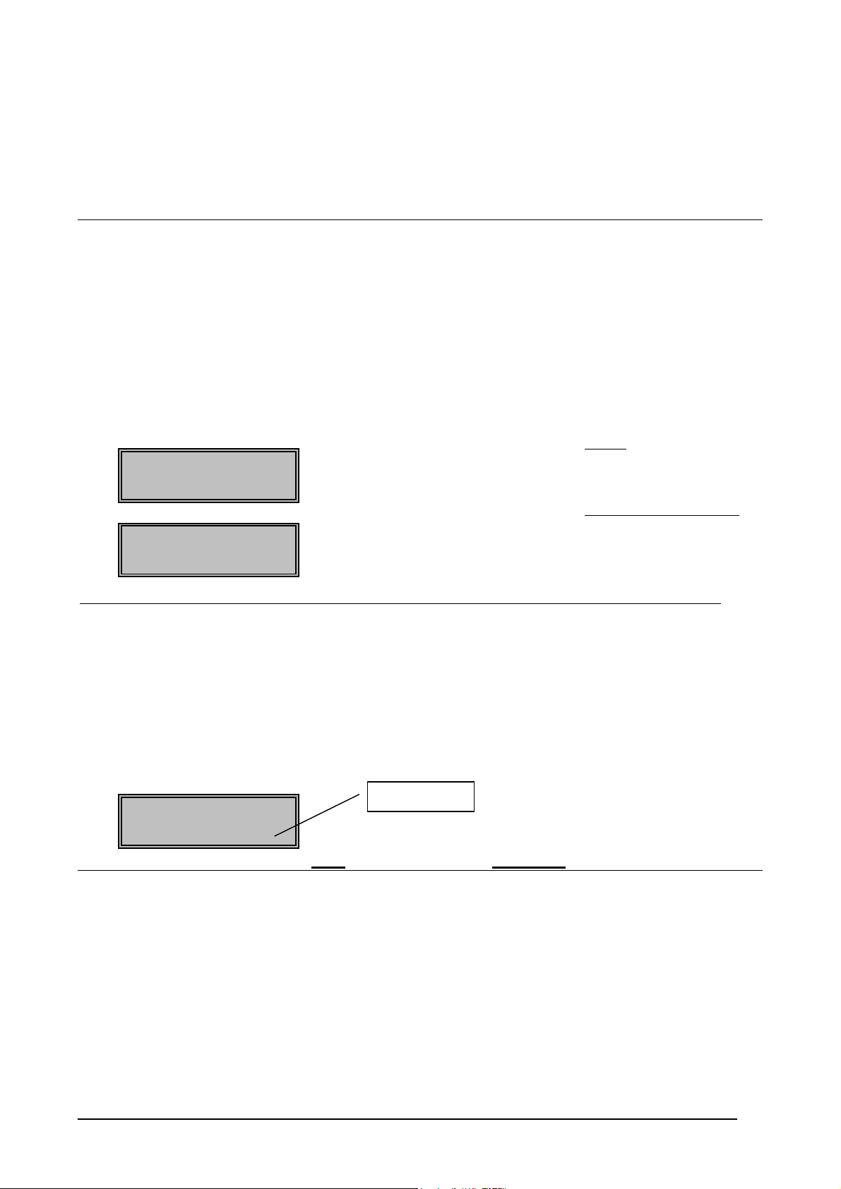
The display will look like this if the Analyzer is oxygen
The display will look like this if the Analyzer is oxygen and carbon dioxide
Oxygen 20.9%
Sensor Deg 720C
O2 20.9% CO2 0.0
Sensor Deg 720C
The 9070 Analyzer is now reading oxygen (and carbon dioxide if installed).
only.
.
Insert the hypodermic through a septum into a food pack to get a gas reading. Leave the hypodermic in the pack
5.
for 4 to 6 seconds, or until the head space is nearly all pumped out. Don’t suck in the food product.
(See question #1, in Frequently Asked Questions on the next page)
If you want to display the minimum oxygen, press the DISPLAY button until the lower line of the display reads
6.
“Sample” like this-
Oxygen 20.9%
Sample 0.68%
Lower Line
Some of the menu items that may have to be set the first time the Analyzer is used…..
Select the “Sample mode” (Setup # 26).
1.
Continuous. When the process gas is available continuously. Eg Gas supply monitoring.
Display Sample. When sampling a gas from a food pack.
Fast Sample When sampling a gas from a food pack with very small head space. (<50cc)
Select the “Display Mode” (Setup # 27)
2.
Oxygen % The oxygen will be displayed as a percentage down to 0.1%, then ppm down to 0.1ppm.
Oxygen PPM The oxygen will always be displayed as parts per million.
O2/CO2 % only The same as ‘Oxygen %’ with carbon dioxide also displayed.
O2/CO2 %/PPM The same as ‘Oxygen PPM’ with carbon dioxide also displayed.
Select the alarm levels, if either a light or a relay contact is required if the oxygen/carbon dioxide is high/low.
3.
Page 2 Teledyne Analytical Instruments 9070 Oxygen Analyzer
Page 3

High Oxygen Setup # 39
Low Oxygen Setup # 41
Very Low Oxygen Setup # 43
High Carbon Dioxide Setup # 45
Low Carbon Dioxide Setup # 47
Select the output range for one or both output channels. ie To allow the oxygen or carbon dioxide to be
4.
transmitted to another instrument.
Channel 1, Setup # 20 to 22
eg Oxygen 0.1 to 100.0%
Low Oxygen 10 to 10,000 PPM
Channel 2, Setup # 23 to 25
eg Sample Oxygen
Low Oxygen
Carbon dioxide
Frequently Asked Questions……..
1. How do I insert the hypodermic needle into the food pack?
Cut a 1.5 cm length of the septum strip. Peal the backing tape off. Squeeze the food pack to get the gas into one place.
Press the septum piece firmly onto the plastic wrapping film. Insert the hypodermic needle into the headspace through
the septum without touching the food product.
Leave the needle in the food pack until the pack has nearly collapsed, or at least 4 seconds for an oxygen measurement,
and 6 seconds for an oxygen and carbon dioxide measurement.
The septum strip will self-seal and can be re-used several times.
2. How often do I have to calibrate the Analyzer?
Oxygen – Once per year.
The 9070 uses the extremely stable zirconia oxygen sensor technology. In addition, the Analyzer automatically
corrects for any drift in the Analyzer.
Carbon dioxide – Every 6 months, or for critical applications every 2 - 3 months.
The carbon dioxide sensor uses a specifically designed infra red source to increase the signal strength and reduce the
effect of sensor drift. However optical measurements are not absolute measurements like the zirconia oxygen sensor,
so occasional checks on a calibration gas confirm the accuracy.
3. Why are there 3 sample modes, and which one should I use?
The 9070 Analyzer can read and display the current level of oxygen and carbon dioxide,
or
It can pick the minimum/maximum oxygen and the maximum carbon dioxide.
Use ‘Continuous’ mode if the Analyzer is to read a continuous supply of gas, such as monitoring a gas blanket over
milk powder.
Use either ‘Display Sample’ or ‘Fast Sample’ if the gas to be tested is in a food pack. The size of the pack will
determine which of these two modes to use. Use Fast Sample if the package has less than 50cc head space. The
Display Sample mode has the added advantage of displaying the oxygen and carbon dioxide levels as they change
through the testing process.
4. Why does the back of the cabinet get so warm?
The zirconia oxygen sensor runs at about 720°C. The small furnace is mounted in the vented section at the back of the
cabinet.
5. When should I replace the small disc filter on the hypodermic needle?
It will depend on the application, but you will know that the filter is blocked when the response time is much quicker
when the filter is removed. The filters are much cheaper than the oxygen sensor. Keep spares handy.
Teledyne Analytical Instruments 9070 Oxygen Analyzer Page 3
Page 4

CONTENTS
1. SPECIFICATIONS
2. DESCRIPTION
3. INSTALLATION & COMMISSIONING
4. OPERATORS FUNCTIONS - ALARMS
5. SETTING UP THE ANALYZER
6. MAINTENANCE
APPENDIX
1. OXYGEN SENSOR EMF TABLES
2. LOGARITHMIC OXYGEN SCALE
3. SAMPLE LOG PRINT OUT
4. CIRCUIT SCHEMATICS
Note: This manual includes software modifications up to Version 7.81, April 14, 1998
© Copyright TELEDYNE ANALYTICAL INSTRUMENTS (AUST.) PTY LTD - 1996
Neither the whole nor any part of the information contained in, or the product described in, this manual may be adapted
or reproduced in any material form except with the prior written approval of Teledyne Analytical Instruments (Aust)
Pty Ltd (Teledyne Analytical Instruments).
The product described in this manual and products for use with it, are subject to continuous developments and
improvement. All information of a technical nature and particulars of the product and its use (including the information
in this manual) are given by Teledyne Analytical Instruments in good faith. However, it is acknowledged that there
may be errors or omissions in this manual. A list of details of any amendments or revisions to this manual can be
obtained upon request from Teledyne Analytical Instruments Technical Enquires. Teledyne Analytical Instruments
welcome comments and suggestions relating to the product and this manual.
All correspondence should be addressed to:
Technical Enquires
Teledyne Analytical Instruments (Aust.) Pty Ltd
16830 Chestnut Street
City of Industry Phone: (626) 961 9221
CA 91749-1580 Fax: (626) 961 2538
USA
All maintenance and service on the product should be carried out by Teledyne Analytical Instruments authorised
dealers. Teledyne Analytical Instruments can accept no liability whatsoever for any loss or damage caused by service
or maintenance by unauthorised personnel. This manual is intended only to assist the reader in the use of the product,
and therefore Teledyne Analytical Instruments shall not be liable for any loss or damage whatsoever arising from the
use of any information or particulars in, or any error or omission in, this manual, or any incorrect use of the product.
Page 4 Teledyne Analytical Instruments 9070 Oxygen Analyzer
Page 5

USING THIS MANUAL
The Teledyne Analytical Instruments9070 Trace Oxygen Analyzer has a variety of user-selectable functions.
They are simple to use because each selection is menu driven. For options you are not sure about, read the manual on
that particular item.
Please read the safety information below and the ‘Installation’ section before connecting power to the Analyzer.
CAUTION 1
The oxygen sensor heater is supplied with mains voltage. This supply has electrical shock danger to maintenance
personnel. Always isolate the Analyzer before working with the oxygen sensor.
The oxygen sensor must
The oxygen sensor which is heated to 720°C (1320°F) in this instrument can be a source of ignition in applications
where fuel gases or very high oxygen percentages (above 50%) are present. For these applications, it will be necessary
to provide a sampling line made of flame proof material, with adequate flashback arresters. If this configuration does
not suit or if it is possible for raw fuel to come into contact with a hot oxygen sensor then the Model 9070 Analyzer
with a heated sensor may be unsuitable for your application.
ALWAYS be connected to EARTH.
CAUTION 2
Teledyne Analytical Instruments 9070 Oxygen Analyzer Page 5
Page 6

SPECIFICATIONS
1
1.1 MODEL 9070 OXYGEN ANALYZER DESCRIPTION
1.2 DETAILED SPECIFICATIONS
1.3 ORDERING INFORMATION
1.4 MODEL SELECTION GUIDE
Page 6 Teledyne Analytical Instruments 9070 Oxygen Analyzer
Page 7

SPECIFICATIONS
1.1 MODEL 9070 OXYGEN ANALYZER DESCRIPTION
The Teledyne Analytical Instruments model 9070 oxygen/carbon dioxide Analyzer/transmitter provides an integrated
instrument for measurement of oxygen and carbon dioxide for food packaging and gas monitoring. The Analyzer
provides local indication of oxygen/carbon dioxide, plus eight other selectable variables, including minimum sample
hold level.
Two linearised 4–20 mA output signals are provided. Alarms are displayed at the Analyzer and relay contacts activate
remote alarm devices every minute.
The 9070 has a keyboard for selecting the output range, display options, alarm levels, etc. The instrument is
microprocessor based and all adjustments are made using the keyboard.
• Used for continuous gas sampling, food pack testing
• Simple to use
• Sensitive down to 0.1 ppm oxygen
• Displays 0.1% carbon dioxide resolution
• Automatic minimum/maximum sample detection, display and output to printer and 4–20 mA signals
• Automatic calibration of oxygen and carbon dioxide offset
• Linear output of % oxygen and carbon dioxide for recording or control
• Built in safety features
• 16 different alarm functions warn the operator of gas composition, sensor or Analyzer problems
• RS 232C/RS 485 printer/computer interface
1.2 DETAILED SPECIFICATIONS
Measuring Range
• 0.1 ppm to 100% oxygen
• 0 to 100 % carbon dioxide
Response Time
• Less than two seconds with a gas flow of 400 cc (50 scfm) per minute, oxygen
• Less than six seconds with a gas flow of 400 cc (50 scfm) per minute, carbon dioxide
Accuracy
• ±1% of actual measured oxygen value with a repeatability of ±0.5% of measured value.
• Carbon dioxide ±3%
Warm Up Time
• Fifteen minutes approximately for optimum accuracy. Useful readings are possible within 10 minutes after
switching the instrument on.
Teledyne Analytical Instruments 9070 Oxygen Analyzer Page 7
Page 8

Outputs
• Two isolated linearised 4–20 mA DC outputs into 1000Ω load (max).
• RS232/485 computer/printer interface for peak oxygen/carbon dioxide value report and alarm functions.
• One common alarm relay for self diagnostic alarms
• One user selectable alarm relays for gas related alarm levels, ‘Sensor low temperature’ and ‘Calibration in
progress’.
Power
• 240/110 VAC, 50/60 Hz, 115W
Gas Connection
• 1/8’’ Swagelok tube connector
Flow Rate
• 200 - 300 cc (25-40 scfm) per minute, governed by internal pump
Environmental
• 0–50°C (32-120°F) ambient temperature
• 0–45°C (32-110°F) ambient temperature when CO2 sensor fitted
Weight
• 4.5 kg (10 lbs)
Dimensions
• 265mm x 158mm x 268mm. (9.91” x 6.22” x 10.55”)
Range of Output 1
• Field selectable from the following:
Output Selection Range
Linear oxygen 0–0.1% oxygen to 0–100.0% oxygen
0–1000ppm oxygen to 0–1,000,000ppm oxygen
Low Range Linear oxygen 0–0.001% oxygen to 0–1.0% oxygen
0–10ppm oxygen to 0–10,000ppm oxygen
Range of Output 2
• Field selectable from the following:
Output Selection Zero Range Span Range
• Carbon Dioxide, 0–90% 10–100% Min span 10%
• Reducing Oxygen 10-1–10
-10
% 10-1–10
-30
%
In one decade steps. Min span three decades
• Oxygen sensor EMF 0–1100 mV 1000–1300 mV
In 100 mV steps In 100 mV steps
• Sample Oxygen 0–0.1% 0.01–20% Min Span 0.01%
0–1000 ppm 100–20,000 ppm Min span 100 ppm
• Low oxygen 0–99.9% 0.1–100% oxygen Min span 0.1%
0-999,000 ppm 1,000-1,000,000 ppm Min span 1,000ppm
• Logarithmic Oxygen 0.1% O2 Fixed 20% O2 Fixed
Range of Indication, Upper Line
• Oxygen selectable either % O2 or ppm, and Carbon Dioxide
• Oxygen, auto ranging from 0.1 ppm to 100% O2 (always ppm below 0.1% oxygen if selected as % O2 in set-up
#27)
Carbon Dioxide, 0.1 to 100.0%
•
Page 8 Teledyne Analytical Instruments 9070 Oxygen Analyzer
Page 9

Indication Choice, Lower Line
Any or all of the following can be selected for lower line display:
Options:
• Oxygen Sensor EMF
• Oxygen Sensor Temperature
• Oxygen Sensor Impedance
• Sample Oxygen/Carbon Dioxide
• Ambient Temperature
• Ambient relative humidity
• Balance gas (Remaining gas after the O2 and CO2 have been subtracted)
• Date - time
• Run Hours since last service
• Date of last service
Relay Contacts
0.5A 24 VAC, 1A 36 VDC •
Mounting
• Desk top. Also available as a surface mount Analyzer with an external oxygen sensor.
1.3 ORDERING INFORMATION
Orders may be placed by submitting the following information (please number each item as below):
1. State if carbon dioxide measurement is required.
2. Minimum and maximum expected oxygen in sample (particularly the minimum value)
3. Other gas constituents (Any combustibles will consume oxygen as they are burnt on the surface of
4. If the gas is under pressure or if the gas must be extracted to the 9070 Analyzer.
5. Gas connection required (1/8’’ Swagelok is standard)
6. Supply voltage (240 or 110 VAC)
7. If auto/manual on-line oxygen gas calibration checking is required.
the sensor)
8. If surface mounting of the instrument is required or if free standing on
rubber feet is preferred.
Ask your local Teledyne Analytical InstrumentsDistributor for assistance in ordering
1.4 MODEL SELECTION GUIDE
There are 3 options/models available within the 9070 range.
9070-1 Oxygen sensor only, with pump.
9070-2 Oxygen sensor only, no pump.
9070-5 Oxygen sensor and carbon dioxide sensor, with pump.
Teledyne Analytical Instruments 9070 Oxygen Analyzer Page 9
Page 10

2 DESCRIPTION
SECTION
NUMBER
2.1 THE ZIRCONIA SENSOR
2.2 THE OXYGEN SENSOR ASSEMBLY
2.3 THE CARBON DIOXIDE SENSOR ASSEMBLY
2.4 THE ANALYZER
2.5 ALARMS
2.6 HEATER SUPPLY FOR THE OXYGEN SENSOR
2.7 THE OXYGEN SENSOR IMPEDANCE
2.8 AUTO CALIBRATION—ELECTRONICS
2.9 AUTO CALIBRATION CHECKING—OXYGEN SENSOR
2.10 AUTO CALIBRATION CHECKING—CARBON DIOXIDE SENSOR
2.11 RS 485/232C PORTS
2.12 AMBIENT TEMPERATURE
2.13 WATCHDOG TIMER
2.14 BACK UP BATTERY
AND RELATIVE HUMIDITY MEASUREMENTS
Page 10 Teledyne Analytical Instruments 9070 Oxygen Analyzer
Page 11
DESCRIPTION
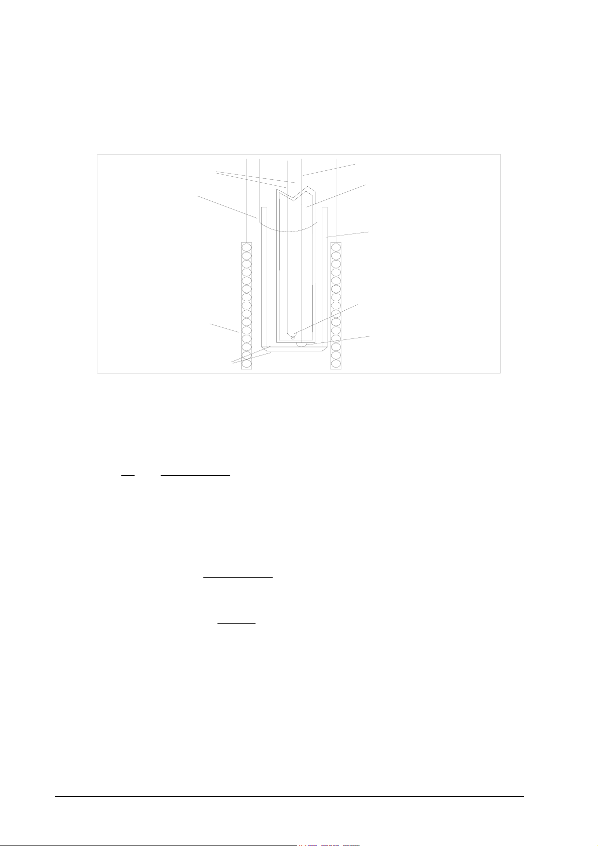
2.1 THE ZIRCONIA SENSOR
The oxygen Analyzer input is provided from a solid electrolyte oxygen sensor which contains a zirconia element and
thermocouple. The sensor is designed to have a small sample of the unknown gas passed into the inside of the sensor
tube, and air (20.95% oxygen) around the outside. A heater is mounted around the sensor to keep the sensor hot. The
sensor construction is shown in Figure 2.1.
Thermocouple
Wires
External Wire
Contact
Internal electrode wire
Four-Bore Thermocouple
Insulating Tubing
Alumina Tube
Heater
(required only
with heated
probes)
Electrode Material
Ziconia Disc
Thermocouple
Junction
Internal Electrode
Fig 2.1 Schematic View of a Sensor Assembly
The heater control is a time proportioning temperature controller and triac so that the thermocouple junction is
controlled to between 720°C (1320°F) and 720°C.
When exposed to different oxygen partial pressures at the outside and inside of the sensor, an EMF (E) is developed
which obeys the Nernst equation:
E (millivolts) =
RT
4F
loge
(PO2) INSIDE
) OUTSIDE
(PO
2
Where T is the temperature (K) at the zirconia disc (>650°C (>1200°F) ), R is the gas constant, F is the Faraday
constant and (PO
) INSIDE and (PO2 ) OUTSIDE are the oxygen partial pressures at the inner and outer electrodes,
2
respectively, with the higher oxygen partial pressure electrode being positive.
If dry air at atmospheric pressure, (21 % oxygen) is used as a reference gas at the inner electrode, the following
equations are obtained:
E (millivolts) = 2.154 x 10
-2
T log
e
) OUTSIDE
(PO
2
0.21
Transposing this equation
(%O
) OUTSIDE (ATM) = 0.21 EXP
2
-46.421E
T
The 9070 transmitter solves this equation which is valid above 650°C (1200°F). The oxygen sensor heater maintains
the sensor temperature at this level.
2.2 THE OXYGEN SENSOR ASSEMBLY
The oxygen sensor assembly provides a means of exposing the zirconia sensor to the atmosphere to be measured on the
inside of the sensor, and maintain air as a reference gas on the outside of the sensor. A small volume, (from as little as
150 cc (20 scfm) /min) of the gas to be sampled is either pumped through the assembly at a known rate by the internal
pump. The gas flow rate may also be monitored by a flow rate switch, which will cause an alarm if the rate falls below
120 cc (15 scfm) /min.
Teledyne Analytical Instruments 9070 Oxygen Analyzer Page 11
Page 12

The sensor assembly also provides the means of maintaining the temperature of the sensor at 720°C (1320°F) by
surrounding the sensor tube with a heater element, and measuring the temperature of the zirconia disc with a
thermocouple inside the sensor. (See Figure 2.1)
2.3 THE CARBON DIOXIDE SENSOR ASSEMBLY
The carbon dioxide sensor assembly is mounted on a circuit board in the 9070 cabinet. The CO
separate microprocessor to control the operation of the CO
cell, maintain calibration and provide a linear output to the
2
sensor PCB has a
2
main 9070 PCB. It has been designed to read carbon dioxide concentrations within the temperature range of 5 to 45°C
(40°F to 110°F), with ambient humidity not exceeding 85% RH. A state of the art temperature compensated sensor is
employed to maintain accuracy and reduce the need for calibration. The range of the CO
sensor PCB is 0 to 100%.
2
The 4-20 (0-20) mA output can be scaled to cover other ranges with a minimum span of 10% carbon dioxide.
The principle of operation is that of absorption of the specially designed infra red light source which is passed through
an analysis cell and a thin film filter into a solid state detector. The filter is selective and passes radiation only in the
carbon dioxide absorption wave band. The detector output is amplified and, with no carbon dioxide present in the cell,
is balanced against a reference voltage to give a zero output voltage.
Absorption of infra red radiation by the gas in the cell reduces the detector signal, leading to a positive voltage
appearing at the sensor output. The gain of the amplifier is adjusted automatically, and the signal is digitally processed.
The carbon dioxide level is transferred to the main 9070 microprocessor via a digital link. Span and zero calibration can
be done from the keyboard of the 9070.
The response from the CO
microprocessor on the CO
cell is non-linear with respect to carbon dioxide percentage, but is linearised within the
2
PCB.
2
Calibrate to ZERO & SPAN once every two months for best performance.
2.4 THE ANALYZER
The 9070 oxygen Analyzer is a microprocessor based, auto–calibrating instrument with a liquid crystal display, two 4–
20 or 0–20 mA output signals, a printer/computer port and four alarm relays with a total of 24 alarm functions.
The display will read in either % oxygen or ppm, as selected in set–up step 27. It is capable of calculating the oxygen
volume from less than 0.1 ppm to 100%. The top line of the LCD is used to display the oxygen and the carbon dioxide
content.
The lower line is used to display nine other variables such as sensor temperature, sensor impedance, date/time etc. The
lower line is also used to display alarm messages such as sensor ‘OXYGEN NOT READY’ and ‘A/D CAL ERROR’,
‘HIGH O2’ etc.
Many of the functions are user variable (such as 4–20 mA output channel ranging), and are changed using a menu
system from the keyboard. Even the one–time calibration is performed using the keypad. (See Section 2.8). The
changes are then all stored in a battery-backed RAM module.
2.5 ALARMS
Refer to OPERATOR FUNCTIONS Section 4 for details on alarm functions.
2.6 HEATER SUPPLY FOR THE OXYGEN SENSOR
CAUTION
The oxygen sensor heater is supplied with mains voltage. This supply has electrical shock danger to maintenance
personnel. Always isolate the Analyzer before working with the oxygen sensor.
The sensor assembly must always be connected to earth.
The heater is supplied from the mains power directly, and the temperature is controlled initially at 720°C (1320°F) after
turn on.
Page 12 Teledyne Analytical Instruments 9070 Oxygen Analyzer
Page 13

2.7 THE OXYGEN SENSOR IMPEDANCE
The oxygen sensor impedance is a basic measurement of the reliability of the oxygen reading. An oxygen sensor with a
high impedance reading will eventually produce erroneous signals. The Analyzer checks the oxygen sensor impedance
every 5 minutes and if the impedance is above the maximum level for a specific temperature then the impedance alarm
will be activated. Typical oxygen sensor impedance is 1 KΩ to 8 KΩ at 720°C (1320°F).
2.8 AUTO CALIBRATION - ELECTRONICS
The Analyzer input section is self calibrating. There are no adjustments. The analog to digital converter input stages
are checked against a precision reference source and calibrated once every three seconds. Should the input electronics
drift slightly then the drift will be automatically compensated for within the microprocessor. If a large error occurs due
to an electronic fault then an ‘ADC CAL FAIL’ alarm will occur.
A one-off calibration procedure of the precision reference sources should never need to be repeated for the instrument
life unless the instrument has been repaired. For a description of the calibration procedure, refer to ‘Set-up Function
Details’, Section 5.5, items 6, 7 8 and 9.
The digital to analog converters or output section of the Analyzer are tested and calibrated when the AUTOCAL button
is pressed, and if they are found to have an error then a ‘DAC CAL ERROR’ alarm will occur. The DAC sections are
re-calibrated by pressing the ‘AUTO CAL’ button on the keyboard while in set-up mode.
All output signals will drop to 0 mA for one second period. It is suggested that a D/A re-calibration be performed after
the instrument has stabilised, approximately 30 minutes after first switching on and after Setting Up The Analyzer
Section 5.5, items 6, 7, 8 and 9 have been completed, and then annually.
2.9 AUTO CALIBRATION CHECKING - OXYGEN SENSOR
The calibration of the oxygen sensor is done automatically at the 20.9% (zero sensor mV), and can be checked with the
on-line automatic gas calibration using a span gas.
Air, 20.9%. While the Analyzer is not doing a process gas measurement (the sample inlet pipe is sucking in air), the
Analyzer can automatically trim the calibration to read 20.9% oxygen. For more details see the set-up section 5.5,
number 10 & 11.
Span gas. On-line automatic gas calibration checking is not normally required, particularly if a gas sampling is
being used. Where it is required however, when continuous gas monitoring is being used, the sensor can be checked for
accuracy on-line. A solenoid valve can admit calibrated gas mixtures into the oxygen sensor via the solenoid valve
under microprocessor control on a timed basis. For details refer to Section 3.6, (Using the Automatic Oxygen Check
System). For details on setting up this facility, refer to set-up steps 30 to 37 in Section 5.5.
During sensor auto calibration checking, the Analyzer output will freeze and remain frozen for a further adjustable
period, allowing the sensor time to recover and continue reading the sample gas oxygen level.
Calibration check gases may be manually admitted by pressing the ‘CAL’ buttons on the keyboard while in ‘RUN’
mode. The Analyzer output is frozen during the pressing of these buttons and immediately becomes active when the
button is released. If calibration gas checking is enabled in the Set-up menu for either gas, an automatic gas cycle can
be started by pressing the ‘CAL’ buttons in RUN mode. The cycle can be terminated by pressing any other button.
When using automatic calibration checking, it is important that the flow rate of both the sample gas and the calibration
gas be approximately the same. To achieve this, the sample gas should not be driven directly into the Analyzer, but
should use a bypass pipe ( ie. A ‘T’ pipe on the inlet to the Analyzer ) that the Analyzer can suck a sample of the
calibration gas from.
2.10 AUTO CALIBRATION CHECKING - CARBON DIOXIDE SENSOR
Integrated into the 9070 Analyzer is a self checking and calibrating system for the CO
For best results when calibrating the CO
board for either span or zero, please observe the following guidelines.
2
Connect the zero or span gas to the inlet and allow the gas to flow for about 30 seconds before initiating a calibration
sequence from the 9070 keyboard.
Use the hypodermic needle to sample the calibration gas from a plastic pipe to maintain the normal use flow conditions.
If a span and zero calibration is to be carried out, always start with the zero calibration first.
cell.
2
Teledyne Analytical Instruments 9070 Oxygen Analyzer Page 13
Page 14

The zero calibration takes longer than the span calibration. The maximum time involved with a zero calibration is
around 50 seconds, and for a span calibration the time is around 30 seconds.
If a calibration has been unsuccessful due to an interrupted gas flow, contaminated calibration gas, or excessive
temperature (ie: >50°C {>120°F} ), re-initiate the calibration from the 9070 keyboard.
Do not under any circumstances tamper with or open the CO
analysis chamber. Doing so will void the manufacturers
2
warranty. There are no user servicable parts inside, and any tampering will drastically reduce it’s performance and
lifetime. Any Analysis chamber sent back for repair which has been tampered with will have to be replaced.
If the carbon dioxide module fails, it should be sent back to the manufacturer for repair, and factory re-calibration.
In addition, there is an automatic process that uses the oxygen signal to enable an offset for the CO
saved. This system ensures that the CO
cell will always read zero when air is flowing in the cell.
2
cell to be read and
2
2.11 RS 485 AND RS 232C PORT
The serial port is for connecting a printer, a data logger, or any computer with an RS 485/ 232-C port. It can be used to
monitor the transmitter and process by logging the values of functions selected in step 53 of the set-up menu in Section
5.5.
The log period may be selected in step 20 for 1 to 2000 minutes for the printer mode or 5 to 1200 seconds for the data
log mode. The baud rate may be set up in step 51.
The protocol for the serial port is eight data bits, one stop bit, no parity.
Alarms, including the time they occurred, will be transmitted to the printer and computer whenever they are first
initiated, accepted and cleared (in the printer mode only).
If ‘Fast Sample or 'Display Sample' is selected in set-up step 26, each time a new minimum rate of oxygen is detected,
this value plus date/time, will also be printed (in the printer mode only).
NOTE: The RS232 port is not available in the model 9070-5 (With carbon dioxide installed).
2.12 AMBIENT TEMPERATURE AND RELATIVE HUMIDITY MEASUREMENTS
Ambient temperature and relative humidity are measured within the Analyzer to improve the accuracy of the oxygen
readings. These reading can be displayed on the lower line of the LCD (see set-up step 29), or may be logged to the
printer/computer port ( see set-up step 53).
2.13 WATCHDOG TIMER
The watchdog timer is started if the microprocessor fails to pulse it within any one second period, (ie. fails to run its
normal program).
The microprocessor will then be repeatedly reset until normal operation is resumed. Reset cycles are displayed by the
‘POWER’ light above the keyboard on the front panel. A steady ‘ON’ light indicates normal operation. If the program
has not resumed normal operation after two attempts to reset, the common alarm relay will be activated. If a successful
reset is achieved, the alarm will be cancelled and the Analyzer will continue to run normally.
2.14 BACK-UP BATTERY
The transmitter’s RAM and real-time clock are backed up by a lithium battery in the event of power failure. All set-up
variables are saved and the clock is kept running for approximately ten years with the power off. The battery module
should be replaced every 8 years. (It is the battery shaped device clipped in a socket labelled M1)
Page 14 Teledyne Analytical Instruments 9070 Oxygen Analyzer
Page 15

INSTALLATION &
COMMISSIONING
SECTION
NUMBER
3.1 ANALYZER DIMENSIONS
3.2 EARTH, SHIELD AND POWER CONNECTIONS
3.3 CONNECTING THE OUTPUT CHANNELS
3.4 CONNECTING THE ALARMS
3.5 CONNECTING THE HORN RELAY
3.6 USING THE AUTOMATIC OXYGEN CHECK SYSTEM
3.7 CONNECTING THE PRINTER
3.8 CONNECTING POWER - COLD START
3.9 CONNECTING POWER - WARM START
3.10 COMMISSIONING - SET-UP MODE
3.11 RUN MODE
3.12 CHECKING THE ALARMS
3.13 THE OXYGEN SENSOR
3.14 SENSOR CALIBRATION - OXYGEN
3.15 SENSOR CALIBRATION - CARBON DIOXIDE
INSTALLATION
COMMISSIONING
3
Teledyne Analytical Instruments 9070 Oxygen Analyzer Page 15
Page 16
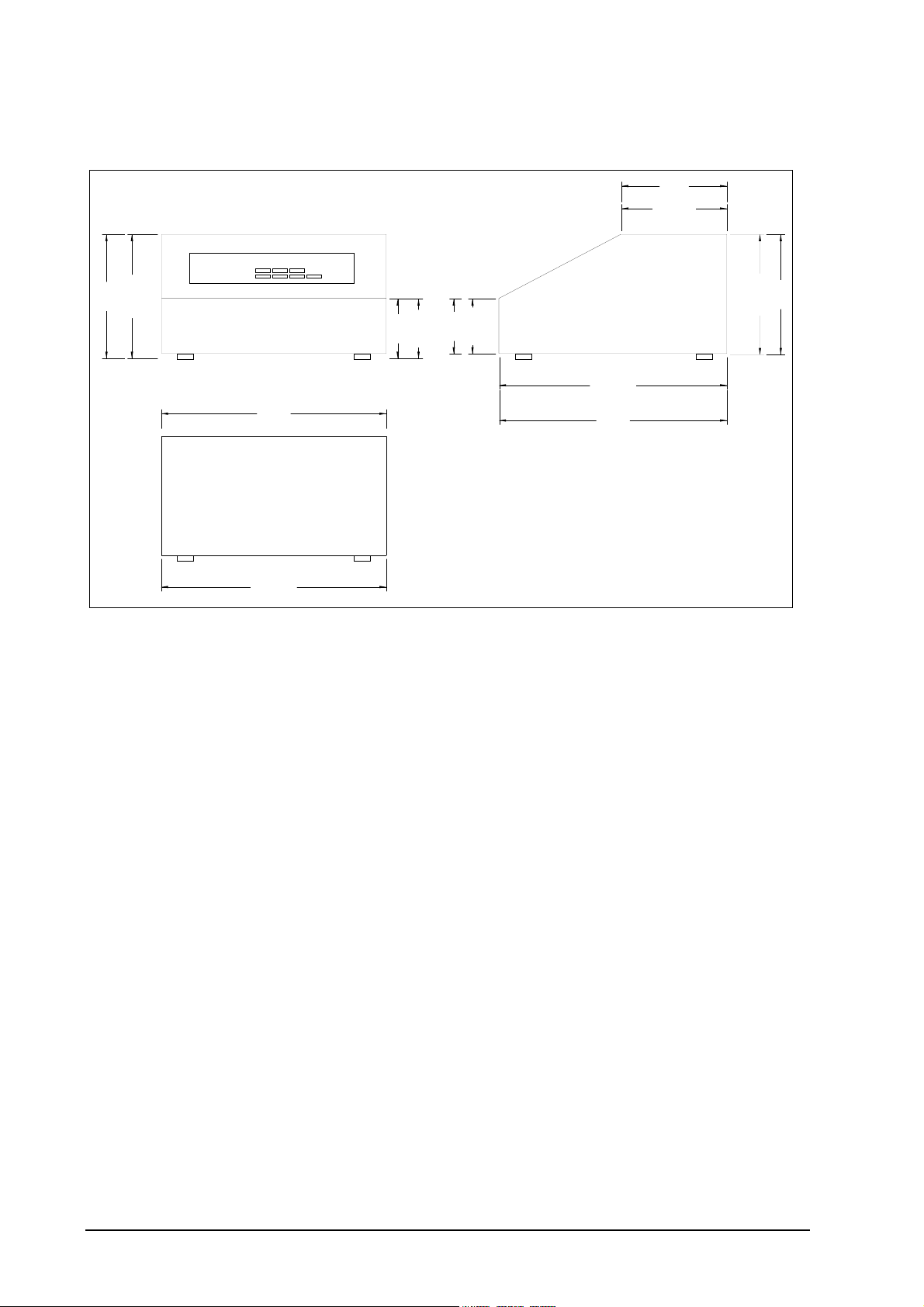
3.1 ANALYZER DIMENSIONS
m
INSTALLATION
4.9"
125mm
6.2"
158mm
FRONT VIEW
10.4"
REAR VIEW
265mm
3.2"
2.5"
83mm
Case Dimensions
65mm
SIDE VIEW
268mm
10.5"
1637 DIMENSIONS.
5.
140m
3.2 EARTH, SHIELD AND POWER CONNECTIONS
All external wiring for the 4–20 mA outputs, alarm relays and printer/computer port should be shielded. All earth and
shield connections should be connected to the earth terminal number 47, and the cabinet earth stud.
The mains earth should be connected to a sound electrical earth.
Do not connect shields at the field end. Simply clip off and insulate. An extra terminal strip may be required to connect
all shields together. This should be supplied by the installer.
IMPORTANT
Before connection of mains power check that the mains voltage selector switch is in the correct position. This switch is
inside the front of the cabinet, below the keyboard. Remove the two top, forward screws and swing the front lid
forward carefully, being careful not to stress the ribbon cables.
Page 16 Teledyne Analytical Instruments 9070 Oxygen Analyzer
Page 17

ELECTRICAL CONNECTIONS
+
-
V
g
p
p
x
x
p
p
p
p
2
2
3
3
4
4
1
1
put
g
y
y
N
A
y
E
l
l
l
l
g
Printer or
Com puter
connection
4- 20m A
out
Selectable
e
ran
Alarm
Rela
Contacts
Normall
Closed
Orange
Brown
Yellow
Red
Probe +
1
Probe -
2
Probe TC+
3
Probe TC-
4
TC2/Aux
5
6
TC2/Aux
7
+12
8
RGCI/P+
9
RGCI/P+
10
Sens #2+
11
Sens #2-
12
Purge Flow Switch
13
Pur
e Flow Switch
14
Fuel 1/2
15
Fuel 1/2
16
Remote Alarm Reset
17
Remote Alarm Reset
18
Burner On In
19
Burner On In
20
RS- 232 R
21
RS- 232 T
22
Network -
23
Network +
24
Serial Common
25
Out
ut 1+
26
ut 1-
Out
27
Out
ut 2+
28
ut 2-
Out
29
Com m on Alarm
30
Com m on Alarm
31
Alarm
32
Alarm
33
Alarm
34
Alarm
35
Alarm
36
Alarm
ut
ut
41
Purge Sol/Htr #2
42
Pur
e Sol/Htr #2
43
Cal 1 So
44
Cal 1 So
45
Cal 2 So
46
Cal 2 So
Mains
47
48
Mains Power Suppl
240/115VAC
Red
Red
OXYGEN SENSOR
49 Mains
50
5152Heater #
Heater #
Mains
Figure 3.2 Internal Oxygen Sensor Connections
All wiring should comply with local electrical codes. All earth and shield connections should be connected to the earth
stud on the LHS inside the case. Before connection of mains power check that the 115 / 230 volt power selector switch
is set to the correct voltage (Lower PCB on the RHS ).
3.3 CONNECTING THE OUTPUT CHANNELS
Teledyne Analytical Instruments 9070 Oxygen Analyzer Page 17
Page 18

The two 4 to 20 mA DC output channels are capable of driving into a 1000Ω load.
25
CH1 O/P+
26
CH1 O/P-
27
CH2 O/P+
28
CH2 O/P-
Connect a maximum
load of 1000 ohms.
Output is 4 to 20mA
DC isolated.
Channel 1
(Oxygen %)
Load
Channel 2
Load (optional)
Figure 3.4 Connections for Transmitter Output Channels.
3.4 CONNECTING THE ALARMS
A common alarm, which should be connected for all installations initiates on alarms functions described below. Three
additional alarm relays are available for selectable functions as listed in Section 4.2 and 4.3. Each relay has normally
closed contacts. The contacts will open in alarm condition except for the optional horn function which operates with
normally open contacts. Relays are connected as follows:
Relay Terminal Numbers
Common Alarm 29 & 30
Alarm 2 31 & 32
Alarm 3 33 & 34
Alarm 4 35 & 36
Common Alarms All of the following conditions will cause a common alarm ADC Calibration Fail
DAC Calibration Fail
Oxygen Sensor Fail
Oxygen Heater Fail
Oxygen Sensor TC Open
Gas Pump Fail
Mains Frequency Check fail
Oxygen Gas Calibration Check Error
Carbon Dioxide Sensor Fail
Watchdog Timer
The watchdog timer is a special alarm. It will force the common alarm to activate in the event of a microprocessor
failure. There will not be an alarm message displayed, but the Analyzer will reset.
Alarms can be accepted by either pressing the alarm button (viewing the alarm messages), or by temporarily closing a
switch connected to terminals 16 & 17, REM ALARM RESET.
Alarm relay 2 to 4 Select any one or all of the following for each relay. Refer to Section 5.5, steps 45 to 47
High oxygen
Low oxygen
Very low oxygen
Oxygen sensor under temperature
Calibration check in progress
Alarm horn function (Relay 4 only)
3.5 CONNECTING THE HORN RELAY
Page 18 Teledyne Analytical Instruments 9070 Oxygen Analyzer
Page 19

The horn relay operates as a true alarm system and can be connected directly to a horn. The horn relay is latching and
6
g
can be reset by pressing the alarm button. The contacts (terminals 28 and 29) will be closed whenever the alarm light is
flashing. Refer to Figure 3.5.
3.6 USING THE AUTOMATIC OXYGEN CHECK SYSTEM
The on-line oxygen calibration system is optional. The gas change-over solenoid must be mounted external to the
cabinet. Typical connection details are shown in Figure 3.5.
For details on its operation refer to Section 2.9.
Mains Voltage 110/240
AC Solenoids
Purge
41
e
Pur
42
Cal 1
43
Solenoid
Cal 1
44
Solenoid
45
Cal 2
Cal 2
4
Solenoid
Figure 3.5 Automatic Oxygen Calibration check Solenoid Connection
3.7 CONNECTING THE PRINTER
20
21
22
23
24
RS 485 network
Serial Port Connections
A printer with a serial port, or a data logger, or a computer terminal may be connected to RS 232-C or the network port.
Data is logged out of the port as arranged in Set-up steps 52 to 54. The baud rate is selectable in set-up step 55. The
RS-232 protocol for the serial port is eight data bits, one stop bit, no parity.
Teledyne Analytical Instruments 9070 Oxygen Analyzer Page 19
Page 20

COMMISSIONING
3.8 CONNECTING POWER - COLD START
Before commissioning the transmitter, read the two Caution paragraphs at the front of this manual.
Check that the mains supply voltage switch is in the correct place for the supply voltage. The mains voltage selector
switch is located on the terminal circuit board, beside the power transformer.
To perform a ‘COLD START’, remove LK1 link, labelled ‘COLD START’ on the 1630-1 PCB (under the shield).
Turn the power on. The Analyzer will load the factory default settings for all of the set-up functions including the
calibration voltages. Replace the cold start link when the message ‘Replace c/s Link’ appears on the LCD.
After a ‘COLD START’, it is advisable to set all new variables in the set-up mode, including calibration voltages, time
and date, however the instrument will be fully operational without any further adjustments.
3.9 CONNECTING POWER - WARM START
A ‘WARM START will be performed when the power is applied with the COLD START link in place. All the set-up
function will have been retained as they were when the power was last turned off in the memory module M1 on the
1630-1 PCB.
3.10 COMMISSIONING - SET-UP MODE
Press the SET-UP button to select the set-up mode. Most of the default settings of the functions will be correct, or will
have been pre-set at the factory. Refer to Section 5.5 for more details.
Check the following set-up functions suit your particular use 1 to 5 Date /time
6 to 9 Reference voltages
11 & 12 Oxygen sensor calibration
20 to 22 Output channel #1
23 to 25 Output channel #2
30 Auto gas calibration checking
39 to 51 Alarm set up
3.11 RUN MODE
When the Analyzer is turned on it will go to RUN mode. The SET-UP/RUN button will toggle between the two
modes. The upper line of the display will now read the oxygen or oxygen and carbon dioxide if the optional carbon
dioxide module has been installed in the front section of the cabinet. If the oxygen sensor temperature is not above
650°C (1200°F), a “Sensor Low Temperature” message be flashed on the lower line. The sensor temperature can be
checked on the lower line of the display.
3.12 CHECKING THE ALARMS
If any alarms are present the alarm LED will be lit, either flashing or steady. To interpret the alarms, press the alarm
button until all alarm functions have been displayed. Rectify the cause of each alarm until no further alarms appear on
the display. For details on the operation of the alarm button and the alarm functions refer to Section 4.
3.13 THE OXYGEN SENSOR
The zirconia oxygen sensor provides an absolute measurement of oxygen partial pressure. There are no calibration
adjustments, apart from ‘SENSOR OFFSET’, which can be selected to be trimmed automatically (See Section 5.5.10 &
5.5.11). The sensor EMF for a span gas is either correct or the sensor is faulty.
To check that the sensor is functioning correctly, firstly check that the high sensor impedance alarm is not activated by
pressing the alarm button if the alarm LED is flashing. The display would show ‘SENSOR FAIL’. The actual
impedance can be displayed on the lower line. It should be less than 3000Ω.
Once it has been established that the sensor impedance is normal, the sensor offset may be tested and set. Refer to
Section 5.5.10 & 5.5.11. A normal flow of air must be in the gas sample line when testing sensor offset.
3.14 SENSOR CALIBRATION – OXYGEN SENSOR
Page 20 Teledyne Analytical Instruments 9070 Oxygen Analyzer
Page 21

There is only one calibration adjustment necessary for the 9070 oxygen sensor. This is the Sensor Offset. An incorrect
value for the sensor offset will affect an oxygen reading at 21% by about 1% oxygen in every 1 mV of offset, but will
have very little effect on oxygen readings below 2% oxygen.
To remove this error, ensure that the normal volume of gas is passing through the gas sample line (approximately 300
cc/min). In this condition, the zirconia sensor should have no oxygen partial pressure difference across the cell. (Air is
also used as reference gas).
NOTE:
If ‘YES’ has been selected in ‘set-up’ step 10, the offset will be automatically trimmed to keep the Analyzer reading
20.9%.
If ‘NO’ has been selected in ‘set-up’ step 10, the offset can been entered manually in set-up 11, by reading the sensor
‘EMF mV’ from the lower line of the display while in ‘RUN’ mode.
A manual gas calibration check may also be performed if an external 2-way solenoid is connected. This may be
performed simply by pressing the ‘CAL 1’ button on the keyboard. The Analyzer electronics should also be calibrated
according to Section 5.5, Set-up Function Details.
3.15 SENSOR CALIBRATION – CARBON DIOXIDE SENSOR
After power has been applied to the 9070, the carbon dioxide transducer will function almost immediately, however it
is recommended that it is allowed to stabilise for about 15 minutes before making any adjustments.
The calibration of the 9070 carbon dioxide module has two main parts Calibration of the ZERO
Calibration of the SPAN
Both parts can be done from the keyboard of the 9070, and the only additional equipment required is a bottle of 100%
carbon dioxide.
Calibrate to ZERO & SPAN once every two months for best performance.
NOTES: -
For best results when calibrating the CO2 sensor, please observe the following guidelines.
• Don’t connect the test gas directly to the sample pipe of the 9070. Allow the Analyzer to suck the gas in using the
internal pump, as it would in normal use. This can be done by piercing a plastic hose on the outlet of the gas bottle
with the hypodermic needle.
• Piercing the plastic hose with the hypodermic needle and allow the gas to flow for about 30 seconds before
initiating a calibration sequence from the 9070 keyboard.
• If a zero and span calibration is to be carried out, always start with the zero calibration.
• The zero calibration takes longer than the span calibration. The maximum time involved with a zero calibration is
around 50 seconds, and for a span calibration the time is around 40 seconds.
• If a calibration has been unsuccessful due to an interrupted gas flow, contaminated calibration gas, or excessive case
temperature (ie: >50°C (120°F) ), re-initiate the calibration from the 9070 keyboard.
• Do not under any circumstances tamper with or open the CO
manufacturers warranty. There are no user serviceable parts inside, and any tampering will drastically reduce it’s
performance and lifetime. Any Analysis chamber sent back for repair which has been tampered with will have to be
replaced.
• If the carbon dioxide module fails, it should be sent back to the manufacturer for repair and factory re-calibration.
ZERO CALIBRATION
CO
2
Leave the sample hypodermic needle open to the air for at least 30 seconds.
Use the function keys to get to set-up mode number 12, “CO
analysis chamber. Doing so will void the
2
Calibrate”.
2
Teledyne Analytical Instruments 9070 Oxygen Analyzer Page 21
Page 22

Select “Cal Zero” and press the ENTER key to lock that selection.
Press the SETUP/RUN key to return to RUN mode.
The display will read -
CO Calibration
2
.......
The zero calibration takes about 50 seconds and as the calibration progresses, more ‘.’ symbols will appear on the
display.
After the calibration is complete, the option in set-up 12 will return to “CO
Cal Done”.
2
SPAN CALIBRATION
CO
2
Insert the sample hypodermic needle into a hose from a gas supply of 100% CO
2.
Open the gas supply and let at least 1 litre per minute flow through the hose. (The 9070 will draw less than 0.5 lpm)
Leave the 100% gas flowing through the Analyzer for at least 30 seconds.
Use the function keys to get to set-up mode number 12, “CO
Calibrate”.
2
Select “Cal Span” and press the ENTER key to lock that selection.
Press the SETUP/RUN key to return to RUN mode.
The display will read -
CO Calibration
2
.......
The span calibration takes about 40 seconds and as the calibration progresses, more ‘.’ symbols will appear.
After the calibration is complete, the option in set-up 12 will return to “CO
Cal Done”.
2
NOTE: It is important that the gas flow rate is the same when using the calibration gas and the sampling gas.
NOTE:
Watch for an alarm on completion of the calibration. If the alarm light is flashing, press the alarm button. If a “Cal Fail
Alarm” is present as a new alarm (the word acc, in lower case, is at the right hand end of the alarm message), the
calibration has NOT been completed successfully. The cause will be because
The gas flow was not stable or
The ambient temperature is too high ( > 45°C (>110°F) )
Re-start the calibration by selecting set-up 12.
Page 22 Teledyne Analytical Instruments 9070 Oxygen Analyzer
Page 23

OPERATOR
FUNCTIONS
4
SECTION
NUMBER
4.1 DISPLAY BUTTON
4.2 ALARM BUTTON
4.3 ALARM SCHEDULE
4.4 POWER LAMP
Teledyne Analytical Instruments 9070 Oxygen Analyzer Page 23
Page 24

OPERATOR FUNCTIONS (RUN MODE)
p
y
rOp
pOxyg
4.1 DISPLAY BUTTON
The upper line on the display will always read oxygen % or ppm, or oxygen % and carbon dioxide.
The following are available for display on the lower line.
1. OXYGEN SENSOR EMF (millivolts)
2. OXYGEN SENSOR TEMPERATURE
3. OXYGEN SENSOR IMPEDANCE, a measure of integrity of the oxygen sensor's electrode.
4. SAMPLE OXYGEN (AND CARBON DIOXIDE)
5. AMBIENT TEMPERATURE
6. AMBIENT RELATIVE HUMIDITY
7. DATE –TIME
8. RUN HOURS SINCE LAST SERVICE
9. DATE OF LAST SERVICE
10. BALANCE GAS (%). A calculation of the balance of the volume of gas being sampled. Oxygen and carbon
dioxide are subtracted from 100% if ‘O
is selected in set-up 26, the BALANCE GAS is calculated from the SAMPLE values of oxygen and carbon
dioxide.
Any number of these variables can be displayed sequentially by pressing the ‘DISPLAY’ button. Items can be selected
for display or deleted in set-up step 29 on the keyboard. In addition to the above lower line displays, the Analyzer will
automatically display:
10 OXYGEN NOT READY, until the sensor is over 650°C (1200°F). If the heater does not get the sensor up to
650°C (1200°F) within 20 minutes, the “OXYGEN NOT READY” message will be replaced by a “HEATER
FAIL” alarm.
11 SENSOR CALIBRATION, occurring for oxygen Cal Gas
/CO2’ is selected in set-up 27. If ‘Display Sample’ or ‘Fast Sample’
2
NOTE
The run time will be the period of time the Analyzer is powered. This timer can be used as a sensor replacement and/or
gas generator service schedule aid. The start time is reset by changing the ‘SERVICE DAY’ in set-up mode.
en % 2.83
Function
Cal 1
Function
Alarm
AlarmDispla
Option
Cal 2
tion
Figure 4.1 Operator's Panel
Setu
Setu
Run
Purge
Ente
4.2 ALARM BUTTON
Page 24 Teledyne Analytical Instruments 9070 Oxygen Analyzer
Page 25

Repeatedly pressing the ‘ALARM’ button will produce alarm displays in sequence on the lower line of the LCD
display. If an alarm has cleared prior to pressing the ‘ALARM’ button, it will not re-appear on a second run through
the alarms. Active alarms which have been previously displayed will have ‘acc’ (accepted in lower case), displayed
alongside. New alarms will not have ‘ACC’ (in upper case) displayed until a second press of the ‘ALARM’ button.
After the last active alarm is indicated, the lower line of the display will return to the last displayed lower line variable.
Alarms may also be accepted remotely by a temporary closure of a switch connected to terminal 16 & 17, ‘REMOTE
ALARM RESET’.
The alarm ‘LED’ will flash when there is an un-accepted alarm. Pressing the ‘ALARM’ button will cause the LED to
go steady if any alarms are still active, or extinguish if there are no active alarms. The horn relay will operate when an
alarm occurs. Pressing ‘ALARM’ will mute a horn relay (if one of the user configureable relays have been selected as
a ‘Horn’ relay) which will re-initiate on any new alarms.
4.3 ALARM SCHEDULE
4.3.1 SUMMARY OF ALARMS - COMMON ALARM
1. ‘Oxygen Sensor Fail’
Oxygen cell or electrode failure (high impedance); (inhibited under 650°C (1200°F) ).
2. ‘Heater Fail’
In the first 20 minutes of power being applied to the heater after being switched on, this alarm will not occur, but a
‘Sensor Low Temp’ display will occur and common alarm relay will be activated. Refer to Section 6.10. If an ADC
alarms occurs, the heater(s) will automatically be turned off.
3. ‘Sensor TC Open’
The oxygen sensor thermocouple is open circuit. The heater will switch off.
4. ‘Ref Pump Fail’
The reference air pump in the Analyzer has failed.
5. ‘ADC Cal Fail’
The analog to digital converter has been found to fall outside the normal calibration specifications. In this case the
oxygen sensor heater will automatically be turned off.
6. ‘Mains Freq’
The sample of the mains frequency has failed.
7. ‘DAC Cal Fail’
The digital to analog and voltage isolator circuit has been found to fall outside the normal calibration specifications.
This check is only performed when the ‘AUTO CAL’ button is pressed. Refer to Section 2.8.
8. ‘Gas Cal Err’
Oxygen sensor does not correctly calibrate to calibration check gas.
9. ‘BB RAM Fail”
The battery backed memory module has failed in service. The device normally lasts 10 years. It is the plug-in battery
like module on the 1630 -1 board, labelled M1.
10. ‘CO
The carbon dioxide module has had a general electronic failure. See set-up 12.
The carbon dioxide module has failed to communicate with the 9070. See set-up 12.
11. ‘CO2 Cal Fail’
The carbon dioxide module has failed to do a complete a calibration. The carbon dioxide module may have measured
the calibration gas at well off the expected level. Re-try the calibration. See set-up 12.
12. ‘CO
The temperature of the carbon dioxide module is too high. Move the 9070 to a cooler operating area. The ambient
operating temperature is 5 to 45°C (40 to 110°F).
13. ‘CO
Gen Fail’
2
High Temp’
2
Gas Drift’
2
Teledyne Analytical Instruments 9070 Oxygen Analyzer Page 25
Page 26

The calibration gas has been unstable during a calibration. Let the gas flow for 30 seconds before starting the
calibration. Re-try the calibration.
14. ‘CO
Lamp Fail’
2
The infra red source in the carbon dioxide module is open circuit. The Analyzer will have to be returned to the factory
for repairs.
12. ‘CO
Coms Fail’
2
The communications link between the carbon dioxide module and the 9070 Analyzer has failed. Try turning the power
off and on. The two LED’s on the inside of the front door should both be flashing to show receive and transmit
activity.
15. ‘CO
Zero Error’
2
The carbon dioxide module and the 9070 are not communicating correctly. Turn the power off and back on again. If
this does not clear the alarm, contact Teledyne Analytical Instruments, service department.
16. ‘Watchdog Timer’
Microprocessor error. This alarm will not appear on the display. The common alarm relay will be forced open circuit.
If the watchdog timer senses a malfunction in the microprocessor, it will attempt to reset the Analyzer every 2 seconds.
After two attempted resets the alarm relay contacts will go open circuit.
4.3.2 SUMMARY OF ALARMS - SELECTABLE ALARMS
There are three user configureable alarm relays. Any or all of the following functions can be selected for each relay.
16. ‘O2% High’
The measured oxygen level is above the level set in set-up 39, and the alarm delay set in set-up 40 has expired. See
Section 5.5.39 for more details.
17. ‘O2% Low’
The measured oxygen level is below the level set in set-up 41, and the alarm delay set in set-up 42 has expired. See
Section 5.5.41 for more details.
18. ‘O2% Very Low’
The measured oxygen level is below the level set in set-up 43, and the alarm delay set in set-up 44 has expired. See
Section 5.5.43 for more details.
19. ‘Sensor Temperature’
The oxygen sensor temperature is under 650°C (1200°F). The oxygen reading is therefore invalid. If the oxygen
sensor heater has been on for more than 20 minutes and the temperature is less than 650°C (1200°F) a ‘Heater Fail’
alarm will occur.
20. ‘Cal in Progress’
An oxygen calibration check is occurring, either manual ( in RUN mode) or automatic
21. ‘High CO2 Alarm’
The measured carbon dioxide level is above the level set in set-up 45, and the alarm delay set in set-up 46 has expired.
See Section 5.5.45 for more details.
22. ‘Low CO2 Alarm’
The measured carbon dioxide level is below the level set in set-up 47, and the alarm delay set in set-up 48 has expired.
See Section 5.5.47 for more details.
23. Alarm Horn
This is not an alarm condition. If one of the three user configureable alarm relays have ‘Alarm Horn’ enabled, the relay
will have closed contacts only when there is an un-accepted alarm on the Analyzer. Press the alarm button twice to
accept any new alarm and to cancel the horn relay. This is only available on relay 4.
4.3.3 ALARM RELAYS
The alarm relays are fail safe. That is, the contacts will be closed during normal operation, and will be open circuit if
there is an alarm or if the power is removed from the Analyzer.
Page 26 Teledyne Analytical Instruments 9070 Oxygen Analyzer
Page 27

4.4 POWER LAMP
Illuminates when power is connected to the Analyzer. If the lamp is flashing, the watchdog timer is attempting to reset
the microprocessor. Replace the 1630-1 microprocessor PCB.
4.5 BURNER BYPASS SWITCH
This switch is mounted on the terminal PCB near the POWER switch.
It does not provide any function in this Analyzer.
Teledyne Analytical Instruments 9070 Oxygen Analyzer Page 27
Page 28

SETTING UP THE
ANALYZER
SECTION
NUMBER
5.1 SET-UP MODE SUMMARY
5.2 SET-UP & RUN MODES
5.3 FUNCTION SELECT
5.4 ENTER OPTION OR VALUE
5.5 SET-UP FUNCTION DETAILS
5
Page 28 Teledyne Analytical Instruments 9070 Oxygen Analyzer
Page 29

SET-UP MODE SUMMARY
5.1 SET-UP MODE FUNCTIONS
1 Calender Year
2 Calender Month
3 Calender Day
4 Real time clock Hour
5 Real time clock Minutes
6 Reference voltage #1
7 Reference voltage #2
8 Reference voltage #3
9 Reference voltage #4
10 Auto oxygen offset, Yes/no
11 Oxygen sensor offset
12 CO
13 Output channel number 1, 4-20 or 0-20mA mode
14 Output channel number 2, 4-20 or 0-20mA mode
15 Output channel number 1 calibration
16 Output channel number 2 calibration
17 Service record year
18 Service record month
19 Service record day
20 Transmitter Output Channel 1 scale
21 Transmitter Zero Channel 1
22 Transmitter Span Channel 1
23 Transmitter Output Channel 2 scale
24 Transmitter Zero Channel 2
25 Transmitter Span Channel 2
26 Sample mode
27 Display mode
28 Centigrade/Fahrenheit Selection
29 Lower Line Display Functions
30 Cal Gas, Yes/no
Set-up steps 31 to 37 may be skipped automatically, depending on the selection in set-up step 30.
31 First Calibration Time
32 Oxygen Content of Cal Gas 1
33 Maximum Acceptable Positive Error Gas 1
34 Maximum Acceptable Negative Error Gas 1
35 Period Between Gas 1 Autocals
36 Duration of Autocal Gas 1
37 Freeze Time Gas 1
38 Reset level
39 High oxygen alarm level
40 High oxygen alarm delay time
41 Low oxygen alarm level
42 Low oxygen alarm delay time
43 Very low oxygen alarm level
44 Very low oxygen alarm delay time
45 High carbon dioxide alarm level
46 High carbon dioxide alarm delay time
47 Low carbon dioxide alarm level
48 Low carbon dioxide alarm delay time
49 Alarm relay number 2 function select
Set-up steps 50 an 51 may be skipped automatically if a version 1.6 of the 9070-2 PCB is installed.
50 Alarm relay number 3 function select
51 Alarm relay number 4 function select
Set-up steps 52 an 55 may be skipped automatically if carbon dioxide is installed..
auto calibration
2
Teledyne Analytical Instruments 9070 Oxygen Analyzer Page 29
Page 30

52 Serial communications mode
53 Data to Print
54 Print Log Period
55 Printer Baud Rate
56 Reference air pump selection
57 Damping factor
5.2 SET-UP & RUN MODES
For the SET-UP mode keyboard to operate, press the SET-UP/RUN button. The set-up light will come on when the
set-up mode has been entered.
NOTE:
Set-up mode cannot be entered if the keyboard lock switch on the inside of the Analyzer is in the UP position. The
keyboard lock switch can be found on the door PCB (1630-2), on the lock side, at the top. If access is attempted while
the keyboard is locked, the message ‘Illegal Access’ will be displayed.
While the Analyzer is in set-up mode the outputs will be frozen. All the of the functions written in BLUE will now
operate. If there are not any buttons pressed for 1 minute the Analyzer will automatically revert to RUN mode.
If purges or an auto-calibration check occurs while the Analyzer is in set-up mode, they will be delayed until the
Analyzer is returned to RUN mode.
To cancel an automatic purge or calibration check cycle, press AUTO CAL button while in RUN mode.
5.3 FUNCTION SELECT
When the SET-UP mode is entered, the Analyzer will automatically display the last set-up function selected.
To select other functions, operate the ‘FUNCTION ’ button to increment to the next function, or ‘FUNCTION ’ to
decrement to the previous function.
5.4 ENTER OPTION OR VALUE
A. Options.
To step through the available options for each function press the ‘OPTION ’ or ‘OPTION ’ buttons.
When the required option is selected press the ‘ENTER’ button. An asterisk will then appear alongside the option
selected. When stepping through the set-up functions, the display will always first indicate the last options entered.
The ‘Lower Line Select’ and ‘Data To Print’ set-up items 29 and 53 are multiple options. One or more options may be
selected for these functions.
B Values
To set a value for a particular function press the ‘OPTION ’ button to increase the value and the ‘OPTION ’ button
to decrease the value. A momentary press will change the value one digit. Holding the button will change the value
more quickly. Once the correct option or value is displayed it can be entered into the Analyzer's memory by pressing
the ‘ENTER’ button. When a value has been entered an asterisk will appear at the R.H.S. of the lower line.
Page 30 Teledyne Analytical Instruments 9070 Oxygen Analyzer
Page 31

p
y
rOp
pOxyg
en % 2.83
Function
Cal 1
Function
Alarm
AlarmDispla
Option
Cal 2
tion
Setu
Setu
Run
Purge
Ente
9070 Oxygen Analyzer Keyboard
5.5 SET-UP FUNCTION DETAILS
Note: The * indicates the default setting after a COLD-START. See Section 6.1
1. Calender year
Options
Select the current year for the real time clock/calender.
The cold start default sets the date and time to the software version date.
2. Calender month
Options
Select the current month for the real time clock/calender.
3. Calender day
Options
Select the current day for the real time clock/calender.
4. Real time clock hour
Options Select the current hour for the real time clock. (24 hour format)
5. Real time clock minutes
Options
Select the current minutes for the real time clock.
6. Reference voltage # 1 ( about 27.5 mV’s )
Options
Set the value of the reference voltage as read on a 3 3/4 digit multimeter (See Section 6.2 for further details).
27.55 mV *
7. Reference voltage # 2 ( about 194 mV’s )
Options
Set the value of the reference voltage as read on a 3 3/4 digit multimeter (See Section 6.2 for further details).
193.60 mV *
8. Reference voltage # 3 ( about 1200 mV’s )
Options
Set the value of the reference voltage as read on a 3 3/4 digit multimeter (See Section 6.2 for further details).
1202.00 mV *
Teledyne Analytical Instruments 9070 Oxygen Analyzer Page 31
Page 32

9. Reference voltage # 4 ( about 2500 mV’s )
Options
Set the value of the reference voltage as read on a 3 3/4 digit multimeter (See Section 6.2 for further details).
2479.00 mV *
Set-up items 6 to 9 are used to calibrate the A/D of the instrument. This should be done 30 minutes or more after the
instrument has been on, approximately once every year. The calibration constants are retained in battery backed
memory unless a ‘COLD START’ is performed. Connect a 3 1/2 digit multimeter negative lead to the test point
marked ‘C’ to the right of the PCB on the inside of the door (labelled ‘REF VOLTS’). Measure the four voltages on
the test point marked 1 to 4 with the positive lead. Refer to Figure 6.2 in the 9070 manual. Enter the measured values
in set-up items 6 to 9. Whenever new values are entered the D/A section should be re-calibrated, Refer to Section 6.3.
10. AUTO OXYGEN SENSOR OFFSET
The sensor offset voltage is produced by small temperature differences within the oxygen sensor. The voltage is
normally between +3 to -3 mV. This error can be automatically removed by selecting ‘YES’.
The only time ‘NO’ should be selected is when the Analyzer is being used to measure gasses with between 16 and 26%
oxygen. The oxygen sensor offset should then be manually entered using set-up step 11.
Options
Yes *
No
11. SET O2 SENSOR OFFSET - MANUAL
The offset only needs to be set manually when the Analyzer is being used to measure gasses within 16 and 26% oxygen
content.
To check a sensor offset on site, the sensor must be sensing air and allowed to settle at the sensor operating temperature
for 30 minutes. Read the offset in ‘RUN’ mode in millivolts on the lower line. Enter the ‘SENSOR OFFSET’ value eg.
if offset value is -1.2 mV, enter -1.2 mV. The typical maximum is +/-3 mV.
If the manual entry method is being used, make sure that ‘NO’ to automatic entry is selected in set-up step 10 or the
manual value will be over written.
A new EMF offset must be entered whenever a new oxygen sensor is installed to calibrate for any offset an individual
sensor may have. This will have been set at the factory for a new or serviced instrument.
12. SELECT CO2 CALIBRATION
Select either ‘ZERO’or ‘SPAN’ calibration of the CO2 module by pressing the enter key in the usual way. Then return
to ‘RUN’ mode. The Analyzer will automatically enter the calibration mode. This will take up to 50 seconds. At the
end of the calibration, the mode selection in the menu will be returned to “CO2 Cal Done ”. A 100% CO2 gas bottle is
required for the ‘Cal Span’.
If ‘ZERO’ is selected, the CO2 module will enter the automatic zero calibration mode. While the zero is being
calibrated, make sure that the sample gas is ambient air. If the sample is not stable during the 50 seconds zero
calibration period, the 9070 Analyzer will abort the calibration and instigate a “Co2 Gas Drift” alarm. If this occurs,
restart the zero calibration.
If ‘SPAN’ is selected, the CO2 module will enter the automatic span calibration mode. While the span is being
calibrated, make sure that the sample gas is 100% CO2. If the sample is not stable during the 30 seconds span
calibration period, the 9070 Analyzer will abort the calibration and instigate a “Co2 Gas Drift” alarm. If this occurs,
restart the span calibration.
Options:
1. CO2 Cal Done *
2. Cal Zero
3. Cal Span
See also section 3.15, SENSOR CALIBRATION - CARBON DIOXIDE.
13. OUTPUT CHANNEL #1, 0-20mA or 4-20mA
Page 32 Teledyne Analytical Instruments 9070 Oxygen Analyzer
Page 33

The 2 output channels can be selected to drive a full scale of either 0 to 20 mA or 4 to 20 mA to represent the parameter
that is selected in set-up functions 20.
Options:
1. 0-20 mA
2. 4-20 mA *
14. OUTPUT CHANNEL #2, 0-20mA or 4-20mA
The 2 output channels can be selected to drive a full scale of either 0 to 20 mA or 4 to 20 mA to represent the parameter
that is selected in set-up 23.
Options:
1. 0-20 mA
2. 4-20 mA *
15. SET CALIBRATION FACTOR FOR CHANNEL #1
The calibration of the 4-20 (or 0-20) mA outputs is done by reading back the output into the input and calibrating this
against a known standard. The standard however, may vary from Analyzer to Analyzer. To allow for this, a trim factor
has been provided to set the calibration of each channel for your particular Analyzer. These two values should only
have to be entered once for the life of the instrument, then the only calibration of the outputs should be to press the
‘AUTOCAL’ button every twelve months.
To determine the calibration factors, generate a full scale value to be sent to the output. eg. For Channel #1, if set-up
steps 21 and 22 were set for a full scale output of 0 to 10% oxygen, then generate input signals until the top line of the
display reads 10% oxygen. This is best done with the use of a Teledyne Analytical Instrumentssimulator test box, but
can also be achieved with a millivolt generator.
Read the output of channel #1 with a three and a half digit multimeter.
ie. The output should be 20mA.
Your meter could read 19.65mA.
In this case as the full scale current is low, increase the calibration factor by about 1% ie. Enter 101.0 %.
Press ‘AUTOCAL’ before leaving the ‘set-up’ mode.
A more accurate way determining the correct factor using the same example -
20.00 to 19.65 = 0.35
( 0.35/19.65 ) *100% = 1.8% error.
Enter the value of 101.8 into ‘set-up’ step 15, 4 to 20 mA #1 CAL, and press ‘AUTOCAL’ before leaving the set-up
mode.
NOTE
The accuracy of the output channels without trimming these factors is generally within 1% after using the ‘AUTOCAL’
procedure. In most cases the instrument can be used without this further trimming of the calibration.
16. SET CALIBRATION FACTOR FOR CHANNEL #2
Follow the procedure set in step 15 for Channel #2.
(It is convenient to use set-up steps 23 to 25 set to Sensor EMF, 0-100 mV.)
17. ENTER SERVICE YEAR
For a new ‘DATE OF LAST SERVICE’, enter the service ‘YEAR’. This can represent the last time the Analyzer was
serviced. It is recommended that the oxygen sensors be refurbished every two years.
18. ENTER SERVICE MONTH
Enter the current ‘MONTH’.
19. ENTER SERVICE DAY
End the current ‘DAY’ of the month. Altering these values will reset the ‘RUN TIME’.
20. TRANSMITTER OUTPUT CHANNEL 1
Select the type of output required from Channel 1. Linear is the most common output required. The low oxygen range
is used for application that have oxygen below 1000ppm (0.1%)
Options:
Teledyne Analytical Instruments 9070 Oxygen Analyzer Page 33
Page 34

1. Linear oxygen (0.1 to 100.0%) *
2. Low range linear oxygen (10 to 10,000 ppm)
The output spans are adjustable in Set-up steps 21 and 22.
21. TRANSMITTER ZERO CHANNEL 1
Select transmitter zero for output Channel 1.
Range 0.0 to 99.9% Oxygen.
Range 0 to 0.999% (9,990ppm) Oxygen.
Default setting is 0.0%.
22. TRANSMITTER SPAN CHANNEL
Select transmitter span for output Channel 1.
Linear Oxygen- Range 0.1 to 100.0% Oxygen. Default setting is 10.0%.
Low Oxygen- Range 0.001 to 1.000% (10 to 10,000ppm) Oxygen. Default setting is 0.100%.
23. TRANSMITTER OUTPUT CHANNEL 2
Select the type of output required for Channel 2.
Options:
1. Sample Gas, oxygen
2. Linear (Low) Oxygen, 0.1 to 100.0 % *
3. Logarithmic oxygen, 0.1 to 20 %
4. % carbon dioxide
5. Reducing oxygen %
6. Oxygen sensor EMF
24. TRANSMITTER ZERO CHANNEL 2
The output zero and span of Channel 2 is set in set-up steps 24 and 25. Range limits are shown below.
25. TRANSMITTER SPAN CHANNEL 2
Output Zero Range Span Range Minium span
SAMPLE GAS, OXYGEN 0.0 to 99.9 % 0.1 to 100 % 0.1 %
LOW OXYGEN 0.0 to 99.9 % 0.1 to 100 % 0.1 %
LOG OXYGEN 0.1 % oxygen fixed 20 % oxygen fixed
(see Note 1)
CARBON DIOXIDE 0 to 80 % 20 to 100.0 % 20 %
REDUCING OXYGEN 10
(see Note 2) oxygen in one oxygen in one
decade steps decade steps.
SENSOR EMF 0 to 1100 mV in 100 to 1300 mV 100 mV
100 mV steps in 100 mV steps
NOTE
1: For log oxygen scale details, Refer to Appendix 2.
2: Note that the reducing oxygen span is shown on the display as the exponent only. -1 represents 10
-1
to 10
-28
% 10
-2
to 10
-30
% Two decades
26. SAMPLE MODE
Options
1. Fast Sample
2. Display Sample *
3. Continuous
-1
% oxygen.
Page 34 Teledyne Analytical Instruments 9070 Oxygen Analyzer
Page 35

Select the option, either ‘Fast Sample’, ‘Display Sample’ or ‘Continuous’ to suit the application.
If a continuous stream of the sample gas is available, then ‘Continuous’ will allow the alarms to trip on the steady state
oxygen level. Set-up step 38 (Reset Level), will be ignored if ‘Continuous’ is selected here.
If however, the gas is coming from a short duration sample, (eg. food packaging sample withdrawn through
hypodermic needle), the minimum value of oxygen may be retained until another sample is read by selecting ‘Fast
Sample’ or ‘Display Sample’. When the valley figure has been confirmed by five further values above the minimum,
the date/time and minimum oxygen value, and the CO2 peak value (if fitted with the CO2 option ), will be sent to the
printer port. The high oxygen alarm will be activated by a high sample level.
‘Display Sample’ mode is very similar to ‘Fast Sample’, except the readings are only taken once per second (10 per
second for Fast Sample). This means for small head space packets (<100 cc (12 scfm) ) the true valley may be missed.
The ‘Fast Sample’ mode is the more precise mode of operation but will not update the display until the valley and peak
values have been found.
If the value in set-up 38 (Reset Level) is above 20.9%, and if a sample hold mode (Fast Sample or Display Sample) is
selected here, the oxygen peak (not valley) will be held as the sample. If the carbon dioxide module is installed, the
peak of carbon dioxide will still be held.
Set-up step 57 (Damping Factor), will only be used if ‘Continuous’ is selected here.
27. DISPLAY MODE
Options
1. Oxygen % *
2. ppm
/ CO
3. O
2 (only available if a CO2 module is installed)
2
/ CO2 % only
4. O
2
(only available if a CO2 module is installed)
The top line of the LCD always shows the oxygen content, but the user may select whether the oxygen will be
displayed as a percentage or in parts per million form. If the CO2 option has been installed, both O2 and CO2 may be
displayed. If option 1 (Oxygen %) is chosen, below 0.1% the display will revert to the ppm form automatically. This
selection also affects other displays such as the 4–20 mA output ranges, gas calibration checking, reset level and alarm
trip levels.
If ‘O2/CO2 %/PPM’ or ‘O2/CO2 % only’ is selected here in set-up step 27, and ‘Fast Sample’ or ‘Display Sample’ was
selected in set-up step 26, the SAMPLE on the lower line of the display will also show the peak level of CO2.
Using ‘O2/CO2 % only’ option restricts the display to the percentage form only. The display will not go into the ppm
mode automatically.
Teledyne Analytical Instruments 9070 Oxygen Analyzer Page 35
Page 36

28. CENTIGRADE/FAHRENHEIT SELECTION
Select whether displays and outputs are to be in ° Celsius or Fahrenheit
Options:
1. Celsius (Centigrade) *
2. Fahrenheit
29. LOWER LINE DISPLAY FUNCTIONS
In the run mode the upper line on the LCD display will always read % oxygen. The lower line can be set to read one or
more of the following. Select as many as are required to be displayed by pressing the ‘ENTER’ button. Those selected
will have an asterisk displayed alongside.
Options:
1. Date to time
2. Run hours since last service
3. Date of last service
4. Oxygen Sensor mV
5. Oxygen sensor temperature
6. Oxygen sensor impedance
7. Sample oxygen ( and Carbon dioxide if fitted )
8. Ambient temperature
9. Ambient relative humidity
10. Balance gas
If options already selected are required to be deleted, select the required option and press the ‘ENTER’ button. The
asterisk will be removed.
30. CALIBRATION CHECK GAS, YES/NO
Select to use on line gas span calibration checking or not.
Options:
No Cal Gas *
Yes
During the timed calibration check periods the transmitter outputs will be frozen and the Analyzer will alarm if
readings are not within the accuracy limits sets in set-up steps 33 and 34. If autocal is not required enter ‘NO CAL
GAS’ and the transmitter will step to set-up 30.
31. FIRST CALIBRATION CHECK
Set the time of day that best suits to start the auto cal gas check.
Range
0 to 23 hours in one hour stops, default 12 o’clock noon
32. OXYGEN CONTENT OF CAL GAS
Enter value of Cal Gas (to one decimal point).
Range:
0.1 to 20.9 % oxygen. Default setting is 8.0 % oxygen.
33. MAXIMUM ACCEPTABLE POSITIVE ERROR GAS
Set the maximum positive error above which the ‘Gas Cal Error’ alarm will be initiated after the timed period set in
set-up step 36.
Range:
0.1 to 3.0 % oxygen. The default setting is 0.5 % oxygen.
34. MAXIMUM ACCEPTABLE NEGATIVE ERROR GAS
Set the maximum negative error below which the ‘Gas Cal Error’ alarm will be initiated after the timed period set in
set-up step 36.
Range:
0.1 to 3.0 % oxygen. The default setting is 0.2 % oxygen.
Page 36 Teledyne Analytical Instruments 9070 Oxygen Analyzer
Page 37

35. PERIOD BETWEEN GAS AUTOCALS
Set the number of hours between autocal Gas 1. A typical time would be 24 or 168 hours. (Daily of weekly).
Range:
1 to 1999 hours. The default setting is 1 hour.
36. DURATION OF AUTOCAL GAS
Set the number of seconds that the autocal gas solenoid will be open. At the end of this period, if the oxygen level
measured is not within the limits set for Cal Gas, a ‘GAS CAL ERR’ will initiate. To determine the minimum time
required for a particular configuration of Analyzer to settle, manually admit cal gas while observing the oxygen reading
in ‘RUN’ mode by pressing the ‘CAL 1’ button. Typical minimum times vary from 5 to 15 seconds.
Range:
0 to 90 seconds. The default setting is 10 seconds.
37. FREEZE TIME GAS
After the Cal Gas period, the transmitter output will remain fixed, (frozen) for an adjustable period to allow the sensor
reading to return to the correct process level and avoid output ‘bumps’. The freeze period time required will depend on
the sensor response time.
Range:
10 to 100 seconds in ten second steps. The default setting is 30 seconds. To determine the required freeze time,
manually perform a calibration check with Gas 1 while the plant is in operation and note the time required for the
reading to return to the correct process level within approximately 0.5 % oxygen.
38. RESET LEVEL
The RESET level is the trip level which triggers the sampling mode capture of the oxygen level.
By setting the reset level below
By setting the reset level above
In order to detect a new ‘SAMPLE’ oxygen or carbon dioxide level, the oxygen reset threshold must be set below (or
above for peak capture) the normal idle oxygen level, but well above (or below for peak capture) the level expected in
the sample period.
This level will not be used if ‘Continuous’ is selected in set-up 26.
Range:
0.1 –100.0% oxygen. The default setting is 15.0 % oxygen.
20.9% the Analyzer will capture a minimum oxygen level.
20.9% the Analyzer will capture a maxiimum oxygen level.
39. HIGH OXYGEN ALARM
Set the operating point for the high oxygen alarm relay.
The high oxygen alarm has a dual range selected by a link on screw terminals 14 & 15 ( FUEL 1/2 ). If the link is
NOT connecting the two terminals, the range will be 0.1 to 30.0 % oxygen. If the terminals have a short circuit link
between them, the range will be 10 to 3000 ppm oxygen.
Range:
0.1 – 30.0% oxygen. The default setting is 10.0 % oxygen.
10 – 3000 ppm oxygen. (With screw terminals 14 & 15 linked)
40. HIGH OXYGEN DELAY ( only available if ‘Continuous’ is selected in Set-up 26 )
Typically set at 30 seconds. This delay is to avoid nuisance alarms when the burner is undergoing transitions in firing
rate which can cause it to deviate from the oxygen set point, but recover quickly.
Range:
0–200 seconds. The default setting is 60 seconds.
Teledyne Analytical Instruments 9070 Oxygen Analyzer Page 37
Page 38

41. LOW OXYGEN ALARM
Set the operating point for the low oxygen alarm relay. Typically set at 2.5% oxygen, depending on the burner, it can be
used as a safety warning.
The low oxygen alarm has a dual range selected by a link on screw terminals 14 & 15 ( FUEL 1/2 ). If the link is NOT
connecting the two terminals, the range will be 0.1 to 30.0 % oxygen. If the terminals have a short circuit link between
them, the range will be 1 to 300 ppm oxygen.
Range:
0.1 –30% oxygen. The default setting is 2.5 % oxygen.
1 –300 ppm. (With screw terminals 14 & 15 linked)
42. LOW OXYGEN DELAY ( only available if ‘Continuous’ is selected in Set-up 26 )
Typically set at 10 seconds.
Range:
0–200 seconds. The default setting is 10 seconds.
43. VERY LOW OXYGEN / FILTER FAIL ALARM
Set the operating point for the very low oxygen alarm level, typically 0.5% oxygen. This limit can be used as an
extreme case alarm level where the normal operating level should never be this low.
If an external combustibles active filter is being used in a wave soldering application, link screw terminals 14 & 15.
This will automatically select the alarm range from 0.1 to 30 ppm. If the measured oxygen level falls below the alarm
level, the alarm message will be “Filter Fail”.
Range:
0.1 –30% oxygen. The default setting is 1.5 % oxygen.
0.1 –30 ppm. (With screw terminals 14 & 15 linked)
44. VERY LOW OXYGEN DELAY ( only available if ‘Continuous’ is selected in Set-up 26 )
Set the very low oxygen alarm delay.
Range:
0–200 seconds. The default setting is 2 seconds.
45. HIGH CARBON DIOXIDE ALARM
Set the operating point for the high carbon dioxide alarm relay.
Range:
0 – 100 % oxygen. The default setting is 40 % carbon dioxide.
46. HIGH CARBON DIOXIDE DELAY ( only available if ‘Continuous’ is selected in
Set-up 26 )
Typically set at 30 seconds.
Range:
0–200 seconds. The default setting is 30 seconds.
47. LOW CARBON DIOXIDE ALARM
Set the operating point for the low carbon dioxide alarm relay. Typically set at 20 % carbon dioxide.
Range:
0 – 100% carbon dioxide. The default setting is 20 % carbon dioxide.
48. LOW CARBON DIOXIDE DELAY (only available if ‘Continuous’ is selected in Set-up
26)
Typically set at 10 seconds.
Range:
0–200 seconds. The default setting is 10 seconds.
Page 38 Teledyne Analytical Instruments 9070 Oxygen Analyzer
Page 39

49. ALARM RELAY #2
Any or all of the following alarm functions may be used to activate the alarm relay. They may be selected or deselected using the ‘ENTER’ buttons as in set-up step 29.
Options :
1. Low oxygen
2. High oxygen
3. Very low oxygen / Filter fail
4. High carbon dioxide
5. Low carbon dioxide
6. Oxygen sensor under temperature
7. Oxygen calibration gas check in progress
50. ALARM RELAY #3
Alarm relay #3 has the same functions available as alarm relay #2. See set-up 49.
51. ALARM RELAY #4
Alarm relay #4 has the same functions available as alarm relay #2. See set-up 49.
In addition an alarm horn function is also available.
If ‘Horn’ is selected it will override any other selections. A relay selected as a ‘Horn’ driver will have the relay
contacts open circuit if there is an un-accepted alarm, and closed when a new alarm occurs.
52. SERIAL COMMUNICATIONS
The RS232/RS485 serial port can be used to log selected data at a minimum 1 minute interval to a printer (see set-up
54) or can be selected to log -Seconds today, Oxygen sensor EMF, Oxygen level, Carbon dioxide level.
The data log period can be set from 5 seconds to 1200 seconds (20 minutes)
Options :
1. Printer *
2. Data logger
53. DATA TO PRINT
Any or all of the following values may be printed on a printer or computer connected to the serial port. They may be
selected or de-selected using the ‘ENTER’ buttons as in set-up step 29. The log period follows in set-up step 54. A
sample of a print-out is contained in Appendix 3. RS to 232C protocol is :
Data word length Eight bits
Stop bits One
Parity None
Oxygen is always printed, plus any of the following
Options :
1. Run hours since last service
2. Date of last service
3. Oxygen Sensor mV
4. Oxygen Sensor temperature
5. Oxygen Sensor impedance
6. Sample oxygen sensor (and carbon dioxide if fitted)
7. Ambient temperature
8. Relative humidity
9. Balance gas
54. PRINT LOG PERIOD
Select the time interval between data print outs on the printer.
Range: 1 to 2000 minutes
55. PRINTER BAUD RATE
Select the correct BAUD rate for data to be transmitted out of the port to the printer.
Options:
300
1200
2400
4800
9600
56. REFERENCE AIR PUMP SELECTION
Teledyne Analytical Instruments 9070 Oxygen Analyzer Page 39
Page 40

There are two pump styles available. The correct style will have been set in the factory. If a cold start is performed, the
wrong style may be wrongly selected. To find out which one is in your Analyzer, undo the 2 screws on the sides and
bring the door forward. If the CM-15 pump has been installed it will be visible on the lower PCB.
Options:
External MV-05 (Black pump mounted on the chassis, rear of the cabinet)
Internal CM-15 (Yellow pump mounted on the 1630-2 PCB) *
57. DAMPING FACTOR
This factor is only used if ‘Continuous’ is selected in set-up 26, Sample Mode.
Each time a new reading is read from the oxygen sensor, the new reading is averaged with the last readings taken,
before the new average is either displayed on the LCD, or sent to the 4 to 20 mA output. The number of readings that
are averaged together is adjustable with this function. A value of five for example, means that the new reading from
the sensor and the previous four readings are averaged together before being displayed. A value of zero entered here
will mean that every new reading from the sensor will be sent to the display unaltered.
The smoothing of the oxygen signal is an exponential function. If a factor of 5 is used, a step change of input signal
will take about 5 seconds to reach 63% of the change on the output/display.
Range
0 to 20. Default setting is 5.
Page 40 Teledyne Analytical Instruments 9070 Oxygen Analyzer
Page 41

MAINTENANCE
6
SECTION
NUMBER
TRANSMITTER MAINTENANCE
6.1 COLD START
6.2 A/D CALIBRATION
6.3 D/A CALIBRATION
6.4 PUMP REPLACEMENT
6.5 BACK TO UP BATTERY REPLACEMENT
6.6 ELECTRONIC REPAIRS
SENSOR MAINTENANCE
6.7 TEST EQUIPMENT REQUIRED
6.8 TESTING AN OXYGEN SENSOR
6.9 OXYGEN SENSOR THERMOCOUPLE
6.10 OXYGEN SENSOR HEATER FAILURE
6.11 CO
OPTICAL SERVICE
2
Teledyne Analytical Instruments 9070 Oxygen Analyzer Page 41
Page 42
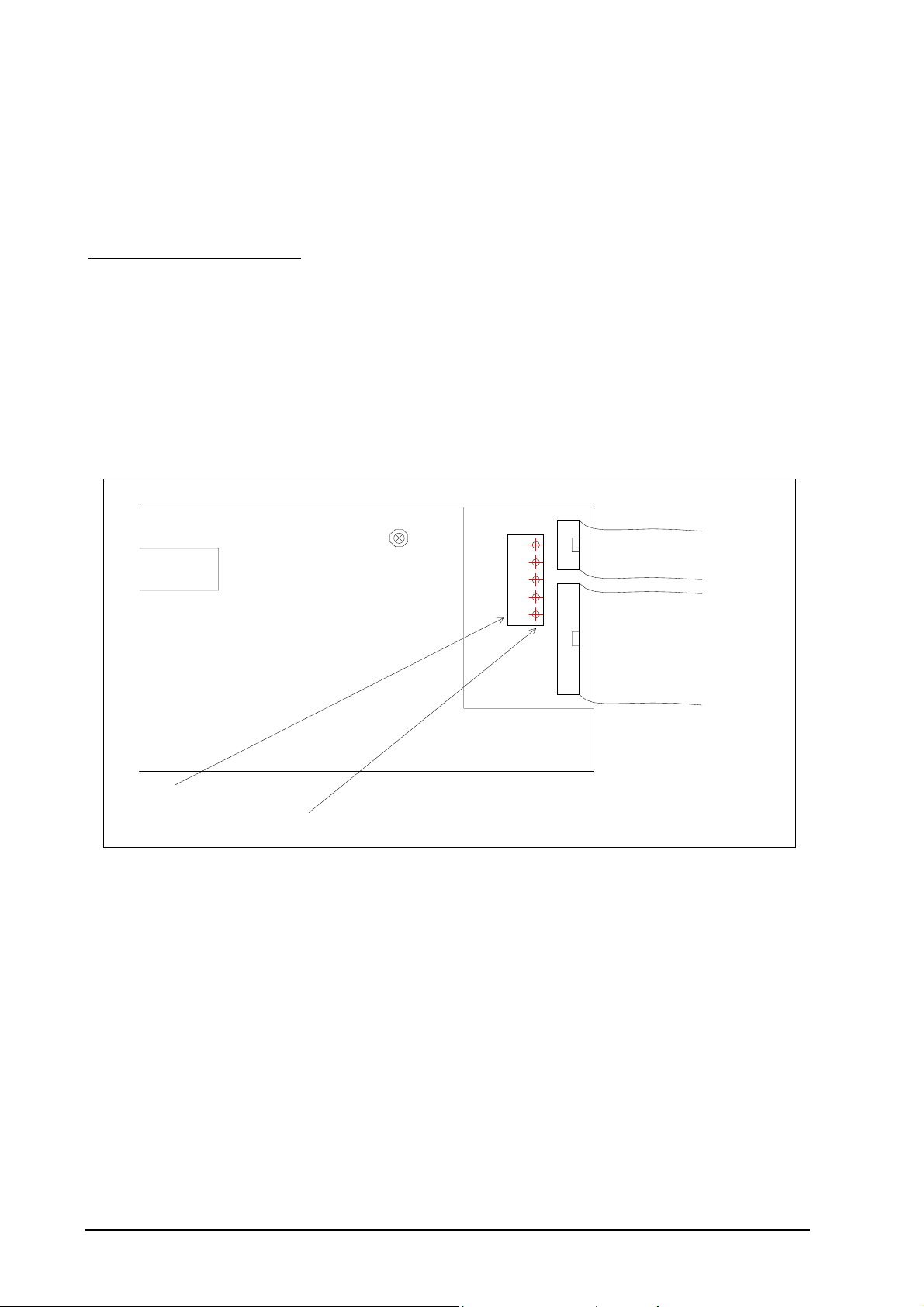
TRANSMITTER MAINTENANCE
p
B
y
y
6.1 COLD START
A ‘COLD START’ will resets all ‘Set-up’ mode entries to their normal default values. ‘COLD START’ will show on
the display for a second prior to a microprocessor initialising sequence, which takes about seven seconds.
After a ‘COLD START’, it is necessary to set all new variables in the set-up mode, including calibration voltages and
time and date.
To initiate a ‘COLD START’ -
Turn the mains power off
Remove the ‘COLD START LINK’ (this is located on the door PCB, next to the keyboard lock switch, behind the
shield)
Turn the mains power on. The message “Cold Start......” will be displayed.
Leave the LINK off until the message “Replace c/s Link” is displayed. Replace the LINK.
The date and version number of the software will be displayed.
A ‘WARM START’, which is performed by applying power with the COLD START LINK in its place, will retain all
data previously entered in the Set-up mode.
6.2 A/D CALIBRATION
16 Wa
Ribbon Cable
Door
Reference
test
oints.
1630-1 PC
Reference
common
40 Wa
Ribbon Cable
Location of Calibration Test Points
The Analyzer maintains its accuracy over a very long by continuously checking itself against internal stabilised
references. The only calibration required is to set the actual values of these references into battery backed memory.
The Analyzer will read these references every minute and update its zero and span correction factors. See Section 5.5.6
to 9.
These references should be checked every 12 months. An AUTOCAL of the analog output section should always be
performed if these references are altered. See Section 6.3.
6.3 D/A (4-20mA output channels) Calibration
If a ‘COLD START’ is performed (Section 6.1), then the D/A section of the Analyzer will be automatically calibrated.
The D/A section should be manually re-calibrated after the instrument has been switched on for 30 minutes and
stabilised. This is achieved by pressing the ‘AUTO CAL’ button while the Analyzer is in the set-up mode. This button
should be pressed annually, or if the reference voltages in the set-up menu are altered. Refer to Section 5.5, items 6, 7,
8, 9, 16 and 17 to re-calibrate the D/A converter and isolated output section. An ‘AUTO CAL’ will be performed after
pressing the button. The transmitter outputs will fall to 0 mA for about a second.
6.4 PUMP REPLACEMENT
Page 42 Teledyne Analytical Instruments 9070 Oxygen Analyzer
Page 43

The reference air pump is mounted on the 1630-2 PCB in the base of the Analyzer. The operation of the pump is
monitored by the Analyzer and alarms will be shown if a fault occurs. (“Pump Fail” alarm )
To replace the pump, unplug all the field wiring terminals. ie. Power connector, sensor connectors etc.
Unplug the 10 way and the 40 way ribbon connectors. Remove the 5 captive screws that retain the terminal PCB in the
base of the case. Remove the PCB from the case. The pump can now be un-screwed, and the wires un-plugged.
6.5 BACK-UP BATTERY REPLACEMENT
The back-up battery is contained within the battery-like real time clock/memory module, plugged into socket M1. It is
rated for an average service life of greater than ten years. The module is not re-chargeable and should be replaced
every three years with a stored transmitters with power off or every eight years with a transmitters which have had the
power on. The memory module must be purchased from Teledyne Analytical Instruments or an agent of Teledyne
Analytical Instruments.
After replacing the battery, re-enter all set-up mode functions.
6.6 ELECTRONIC REPAIRS
Electronic schematics are included in Appendix 4. A competent electronic technician could perform troubleshooting
with these schematics, aided by the Analyzer self-diagnostic alarms. It is recommended that service be performed on a
change-over circuit board basis. A fast turn-around or replacement service is available from Teledyne Analytical
Instrumentsor accredited service agents. Other service aids, including a test EPROM firmware package and sensor
input simulator are also available.
6.7 TEST EQUIPMENT REQUIRED
All measurements are simplified if a 9070 Analyzer is connected to the oxygen sensor. Readings can then be easily
taken of sensor impedance, EMF, temperature and percent oxygen. The Analyzer also provides proper heater control
for heated sensors.
First check all alarms on the Analyzer, allowing time for the sensor to heat up after switch on.
An instrument to measure sensor EMF and temperature is required. A 3 1/2 or 4 1/2 digit multimeter will perform both
measurements.
A separate temperature indicator to suit the sensor ‘K’ type thermocouple is also useful, although not necessary.
A cylinder of calibration gas is required, eg. 2.0 % oxygen in nitrogen. The cylinder should have a pressure and flow
regulator. Both of these are inexpensive devices available from gas supply companies. The calibration gas should be
chromatograph tested to an accuracy of 0.1 % oxygen.
6.8 TESTING AN OXYGEN SENSOR
With the sensor tip heated to approximately 720°C (1320°F), connect a digital multimeter to the sensor electrode
conductors, terminals 1 and 2. If a multimeter is not available, the EMF reading may be taken from the lower line of the
display. Apply approximately 300 cc (36 scfm) /minute of air to the inlet port. The multimeter should read zero
millivolts +
If not, then there is a problem with the sensor electrodes and the sensor needs refurbishing. Normally a faulty sensor
electrode is indicated with a high source impedance. This can be measured on the lower line of the 9070 display
To test the source impedance, use the sensor impedance display on the lower line. Refer to Section 5.5.29, Lower Line
Display Functions. If the impedance is above 3kΩ, then the electrode needs refurbishing.
Where a sensor electrode requires refurbishing it is suggested that they should be returned to Teledyne Analytical
Instrumentsor an accredited service organisation.
If the sensor tests reveal less than 2 mV offset and a good impedance reading, the next step is to apply a calibration gas.
The calibration gas should be inserted in the normal inlet port of the 9070, at the same flow rate as used when in use.
With the calibration gas flowing, the sensor should develop an EMF according to the tables in Appendix 1. If the EMF
reading is low then there may be insufficient calibration gas flow. Increase the calibration gas slightly until the reading
is correct. An excessive calibration gas flow will cause cooling on one surface of the sensor, giving temperature
differential errors on the sensor.
2.0 millivolts.
Teledyne Analytical Instruments 9070 Oxygen Analyzer Page 43
Page 44

If the calibration gas flow is high and it is left to flow on a sensor at a high temperature for more than about 15 seconds,
the ceramic parts of the sensor and sensor sheath can be cooled to the point where, when the flow is removed, they can
break due to thermal shock. If the flow is kept on for a long time it should be reduced slowly to allow the ceramic
surfaces to heat at a rate of not more than 100°C (210°F) per minute.
The sensor accuracy should be within 1% of the EMF according to the tables, with the same offset which was measured
with air on both sides of the sensor. If the sensor EMF is not within this tolerance, then it will require the electrodes to
be refurbished.
Occasionally, a sensor can develop offset with a polluted electrode caused by contaminants in the sample gas stream.
In this case, the old electrode material must be completely cleaned off before re-applying the fresh electrode material.
Again, return the sensor or sensor to Teledyne Analytical Instrumentsor an accredited service organisation.
6.9 OXYGEN SENSOR THERMOCOUPLE
The oxygen sensor is fitted with a ‘K’ type thermocouple to measure the temperature of the oxygen sensor. This
temperature is used in the calculation of oxygen and the control of the heater. The Analyzer has an alarm function
which will advise the operator of an open circuit thermocouple, however bench testing can be performed by simply
measuring the thermocouple continuity.
6.10 HEATER FAILURE
A heater failure will cause a ‘Sensor Temperature’ or ‘Heater Fail’ alarm. Heaters can be tested with a continuity test.
The heater impedance should be approximately 100Ω. Should the heater be open or short circuited, replace the sensor
assembly.
6.11 CO2 OPTICAL SERVICE
Ensure that a particle filter is always fitted on the hypodermic needle to protect the CO
Do not under any circumstances tamper with or open the CO
analysis chamber. Doing so will void the
2
manufacturers warranty. There are no user serviceable parts inside.
Any tampering will drastically reduce it’s performance and lifetime. (Factory calibration values will be disturbed)
If the carbon dioxide sensor fails, it should be sent back to the manufacturer for repair, and factory re-calibration.
analysis chamber.
2
Page 44 Teledyne Analytical Instruments 9070 Oxygen Analyzer
Page 45

APPENDICES
1. OXYGEN SENSOR EMF TABLE
2. % OXYGEN SCALE TO LOGARITHMIC
3. SAMPLE LOG PRINT OUTS
4. CIRCUIT SCHEMATICS
Teledyne Analytical Instruments 9070 Oxygen Analyzer Page 45
Page 46

APPENDIX 1
ZIRCONIA OXYGEN SENSOR OUTPUT (mV)
ZIRCONIA OXYGEN SENSOR OUTPUT (mV)
% OXYGEN mV at 720°C (1320°F) PPM OXYGEN mV at 720°C(1320°F)
_____________________________________________________________________
20.0 0.99 ( 1000 ppm = 0.1%)
19.5 1.53 1000 114.4
19.0 2.09 950 115.5
18.5 2.66 900 116.6
18.0 3.25 850 117.9
17.0 4.47 800 119.2
16.5 5.11 750 120.5
16.0 5.77 700 122.0
15.5 6.45 650 123.6
15.0 7.15 600 125.3
14.5 7.87 550 127.2
14.0 8.62 500 129.2
13.5 9.40 450 131.5
12.5 11.05 400 134.0
12.0 11.92 350 136.9
11.5 12.83 300 140.2
11.0 13.78 250 144.1
10.5 14.78 200 148.8
10.0 15.82 150 155.0
9.5 16.92 100 163.7
9.0 18.08 50 178.5
8.5 19.30 40 183.3
8.0 20.60 30 189.4
7.5 21.98 20 198.1
7.0 23.45 10 212.9
6.5 25.04
6.0 26.75
5.5 28.61
5.0 30.65
4.5 32.90
4.0 35.42
3.5 38.28
3.0 41.58
2.5 45.48
2.0 50.25
1.5 56.41
1.0 65.08
0.5 79.91
0.2 99.51
0.1 114.39
_______________________________________________________________________________
'K’ TC mV 29.965
These tables are based on the Nernst equation:
Sensor e.m.f. = 0.02154 x T x 1n (20.95/% oxygen), where T = ° K (° C + 273).
Page 46 Teledyne Analytical Instruments 9070 Oxygen Analyzer
Page 47

APPENDIX 2
% OXYGEN SCALE to LOGARITHMIC
% OXYGEN % FULL SCALE
0.15 7.66
0.2 13.1
0.3 20.7
0.4 26.2
0.6 33.8
0.8 39.2
1 43.5
1.5 51.1
2 56.5
3 64.2
4 69.6
6 77.3
8 82.7
10 86.9
12 90.8
14 93.3
16 95.8
18 98
20 100
0.1 0
Teledyne Analytical Instruments 9070 Oxygen Analyzer Page 47
Page 48

APPENDIX 3
SAMPLE LOG PRINT OUTs
Teledyne Analytical Instruments 21-02-1996 14:27:30
OXYGEN 1.23 %
CARBON DIOXIDE 31.3 %
Servc'd 20/02/96
Emf 15.2mV
Sensor Deg 703C (1297°F)
Sensor Imp 0.1K
Sample Oxygen = 853 ppm
Ambient T 24.3C (75.7°F)
Ambient RH 67%
Next Print at 14:30:30 21-02-1996
Sample log print out using ‘Printer’ mode ( Section 5.5.48, set-up 52)
61559 15.2 10.130 0
61575 15.2 10.130 0
61591 15.2 10.131 0
61607 15.2 10.131 0
61623 15.2 10.130 0
61639 15.2 10.131 0
61656 15.2 10.131 0
61672 15.2 10.130 0
Sample log print out using ‘Logger’ mode ( Section 5.5.48, set-up 52)
( Seconds-today, oxygen-sensor-EMF, Oxygen%, Carbon dioxide% )
Page 48 Teledyne Analytical Instruments 9070 Oxygen Analyzer
Page 49

APPENDIX 4
CIRCUIT SCHEMATICS
Teledyne Analytical Instruments 9070 Oxygen Analyzer Page 49
Page 50

9070 ALTERATIONS
16/05/97
Add imperial dimensions in brackets. E.g. (100°F)
10/06/97 June 97
Page 5, Section 1.2, detailed specs., CO2 range, 0-10% removed.
Changes to set-up 21 to 23 channel 1 & 2 ranges, page 31.
Step 27 set-up changed to include peak hold.
Set-up 39 changed to include peak hold.
29/01/98 January 1998
Added page 2 & 3 quick start pages.
Added a note about RS232 and the 9070-5 to page 14.
Updated the carbon dioxide calibration in chapter 3.
Removed quick span calibration.
Updated the alarm list on page 25.
Updated the set-up menu and numbering.
18/05/98 May 1998
Removed the 30% and quick span comments on pages 12 and 21
Changed the version and date on page 4
Page 50 Teledyne Analytical Instruments 9070 Oxygen Analyzer
 Loading...