

Page 1
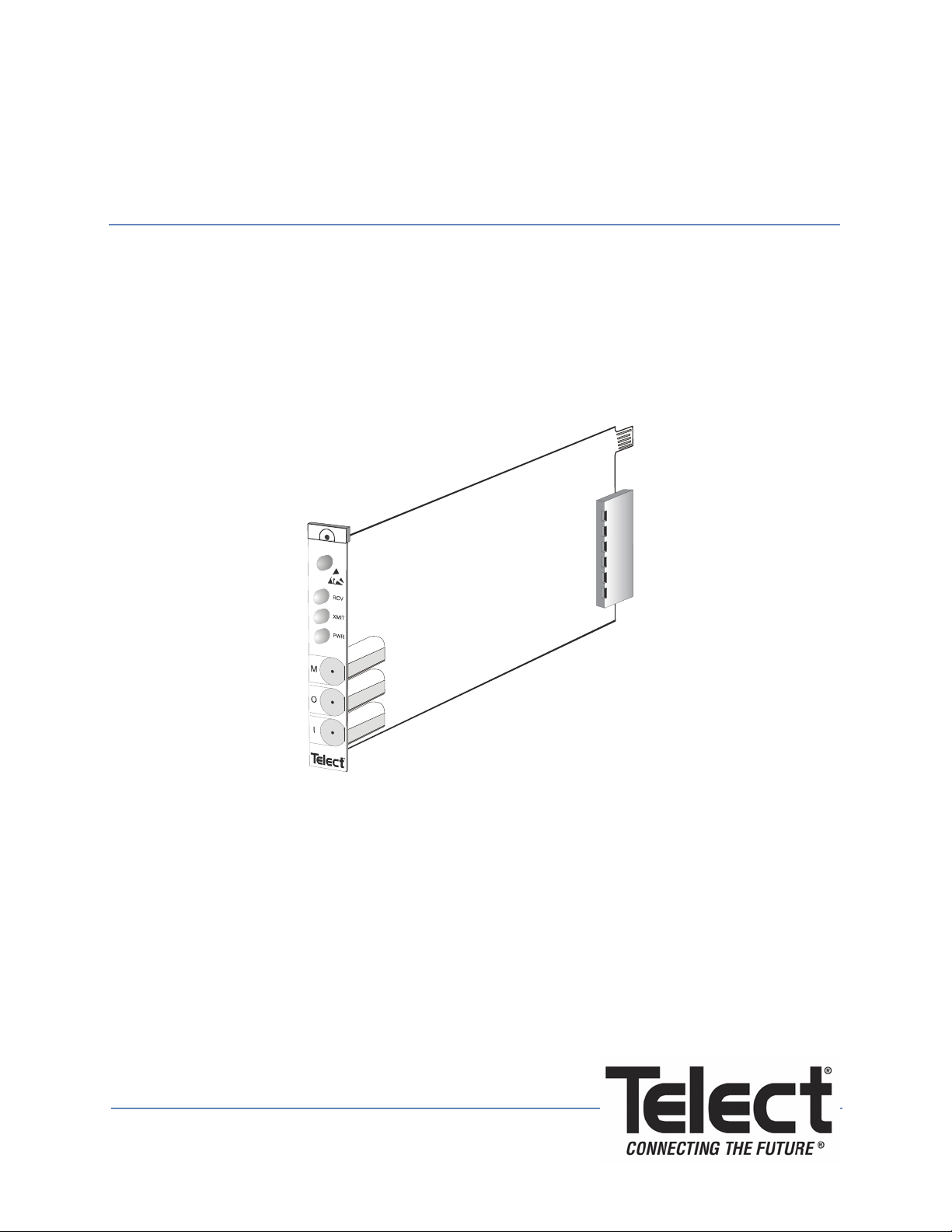
BCS II Simplex Repeater
User Manual
Page 2

BCS II Simplex Repeater
User Manual, Part Number 117209
Copyright 2010, Telect, Inc., All Rights Reserved
Telect and Connecting the Future are registered trademarks of Telect, Inc.
1730 N Madson St., Liberty Lake, Washington
Telect assumes no liability from the application or use of these products. Neither does Telect convey any
license under its patent rights nor the patent rights of others. This document and the products described
herein are subject to change without notice.
About Telect
Telect offers complete solutions for physica l layer connectivity, power, equipment housing and other
network infrastructure equipment. From outside plant and centra l office to inside the home, Te lect draws on
more than 25 years of experience to deliver leading edge product and service solutions. Telect is
committed to providing superior customer serv ice and is capable of meeting the dynamic demands of
customer and industry requirements. This commitment to customer and industry excellence has positioned
Telect as a leading connectivity and power solution provider for the global communications industry.
Technical Support
E-mail: [email protected]
Phone: 888-821-4856 or 509-921-6161
Telect, Inc. • USA +1.509.926.6000 • Mexico +52.33.3836.37.52
www.telect.com • © 2010 Telect, Inc., All Rights Reserved, 117209-1 A0
Page ii
Page 3

BCS II Simplex Repeater
User Manual
Table of Contents
1.1 Description .............................................................................................................................1
1.1.1 Features ........................................................................................................................ 1
1.1.2 Specifications ................................................................................................................1
1.2 Schematic ..............................................................................................................................5
1.3 System-Level Application ....................................................................................................... 5
2.1 Installation.............................................................................................................................. 6
2.1.1 Installation Considerations ............................................................................................6
2.2 Installing the Repeater ...........................................................................................................7
3.1 Operation .............................................................................................................................11
3.1.1 Monitoring ................................................................................................................... 11
3.1.2 Loopbacks ...................................................................................................................11
3.1.3 Patching ......................................................................................................................12
4.1 Service .................................................................................................................................12
4.1.1 Owner Maintenance ....................................................................................................12
4.1.2 In Case Of Difficulty ....................................................................................................13
4.1.3 In-Warranty Service ....................................................................................................13
4.1.4 Out-Of-Warranty Service ............................................................................................13
4.1.5 Repacking For Shipment ............................................................................................14
List of Figures
Figure 1 - Dimensions ..................................................................................................................4
Figure 2 - Schematic..................................................................................................................... 5
Figure 3 - Network Element Locations ......................................................................................... 6
Figure 4 - Jumper Settings ........................................................................................................... 8
Figure 5 - Connecting Two Network Elements .......................................................................... 10
Figure 6 - Non-intrusive Signal Monitoring .................................................................................11
Figure 7 - Inserting a Mini-WECO Looping Plug ........................................................................ 11
Figure 8 - Patching ..................................................................................................................... 12
Figure 9 - Inserting the LED .......................................................................................................13
Telect, Inc. • USA +1.509.926.6000 • Mexico +52.33.3836.37.52
www.telect.com • © 2010 Telect, Inc., All Rights Reserved, 117209-1 A0
Page iii
Page 4

BCS II Simplex Repeater
User Manual
1.1 Description
The Broadband Connectivity System II (BCS II) Simplex Repeater (part # 710-3201-0002)
regenerates DS3, E3, and STS-1 signals to allow increased separation of network elements and
provides full DSX functionality. The module fits in any vertical BCS II chassis or in the Vector
chassis and is always installed in pairs.
1.1.1 Features
• Full signal regeneration to equal level point on each circuit
• Mini-WECO monitor and I/O jacks
• Alarm and tracer lamp LEDs
• Full DSX functionality, including patching, monitoring and loopbacks
1.1.2 Specifications
1.1.2.1 Electrical
Monitor Level: 20 dB +
Return Loss: <
Impedance: 75Ω (+/- 5%)
1.1.2.2 Power
Battery Input: A and B redundant, -42 to -58 Vdc
Input Current: 35 mA nominal @ 48V
Internal Fuse: 1/4 amp, not field replaceable
1.1.2.3 DS3 Input
Data Rate: 44.736 Mb/s +
Data Format: Bipolar with B3ZS coding
Jitter Tolerance: Meets requirements of Telcordia GR-499-CORE, Issue 1, December, 1995
Equalization: Selectable normal or high sensitivity receive equalization, based on receive
cable length
-24 dB at DS3 signal rate
1.5 dB below signal level
100 ppm
Telect, Inc. • USA +1.509.926.6000 • Mexico +52.33.3836.37.52
www.telect.com • © 2010 Telect, Inc., All Rights Reserved, 117209-1 A0
Page 1
Page 5

1.1.2.4 DS3 Output
Data Rate: Same as input signal, transmit clock is recovered from input signal. Under AOS
condition (no valid input): 44.736 Mb/s +
100 ppm
Data Format: Bipolar with B3ZS coding, input bipolar violations are transparent to output.
Pulse Shape: Complies with Telcordia GR-499-CORE, Issue 1, December, 1995. Pulse plate
complies with ANSI T1.404 pulse template.
LBO: Selectable DSX Level or DS3 High Output
1.1.2.5 E3 Input
Data Rate: 34.368 Mb/s +
100 ppm
Data Format: AMI with HDB3 coding
Jitter Tolerance: Meets ITU-T G.832, 1993 requirements
Equalization: Selectable normal or high sensitivity receive equalization, based on receive
cable length.
1.1.2.6 E3 Output
Data Rate: Same as input signal, transmit clock is recovered from input signal.
Data Format: AMI with HDB3 coding
Pulse Shape: Complies with ITU-T G.703
LBO: Fixed transmit level
1.1.2.7 STS-1 Input
Data Rate: 51.84 Mb/s +
100 ppm
Data Format: Bipolar with B3ZS coding
Jitter Tolerance: Meets Telcordia GR-499-CORE, Issue 1, December, 1995 requirements
Equalization: Selectable normal or high sensitivity receive equalization, based on receive
cable length.
1.1.2.8 STS-1 Output
Data Rate: Same as input signal, transmit clock is recovered from input signal.
Data Format: Bipolar with B3ZS coding
Pulse Shape: Complies with Telcordia GR-CORE-253
LBO: Selectable DSX Level or STS-1 High Output
Telect, Inc. • USA +1.509.926.6000 • Mexico +52.33.3836.37.52
www.telect.com • © 2010 Telect, Inc., All Rights Reserved, 117209-1 A0
Page 2
Page 6
1.1.2.9 Alarms
Relay contacts rated for 2 amps maximum.
ALARM OUTPUTS, LEDs CONDITION
RCV LED GREEN / XMIT LED GREEN /
ALARM CONTACTS OPEN
RCV LED RED / XMIT LED AMBER / MAJ
ALARM CONTACT CLOSED
XMIT LED RED / MAJ ALARM CONTACT
CLOSED
ALL FRONT PANEL LEDS OFF / PWR FAIL
ALARM CONTACT CLOSED
NORMAL: VALID INPUT SIGNAL
LOSS OF VALID INPUT SIGNAL / ALL ONES SIGNAL AUTOMATICALL Y TRANSMITTED
TRANSMITTER FAILURE
FAIL URE OF INTERNAL POWER CONVERTER OR
LOSS OF BOTH BATTERY INPUTS
1.1.2.10 Environmental
Humidity: 95% relative humidity, noncondensing
Temperature: Operational from 0-50°C
Heat Dissipation: 5.7 BTUs/hour
Telect, Inc. • USA +1.509.926.6000 • Mexico +52.33.3836.37.52
www.telect.com • © 2010 Telect, Inc., All Rights Reserved, 117209-1 A0
Page 3
Page 7
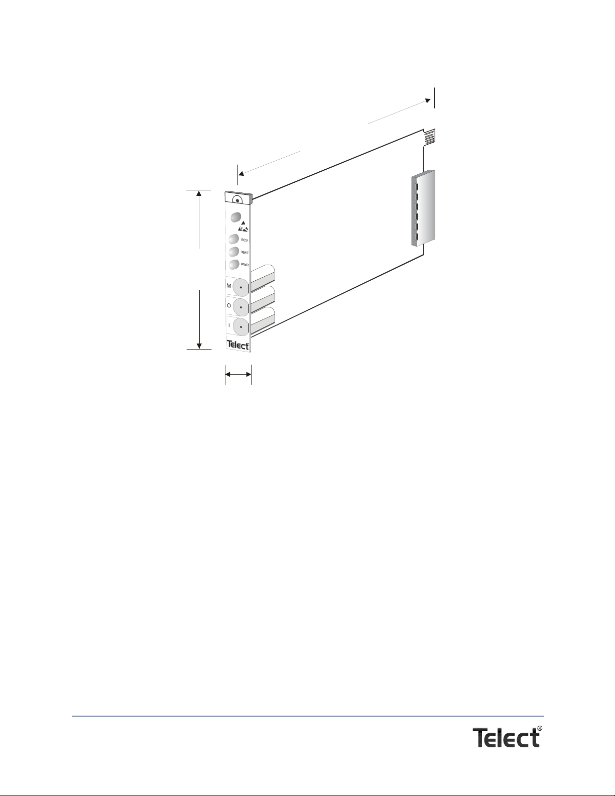
1.1.2.11 Dimensions
3.90 in.
9.91 cm
6.84 in.
17.37 cm
0.65 in.
1.65 cm
Figure 1 - Dimensions
Telect, Inc. • USA +1.509.926.6000 • Mexico +52.33.3836.37.52
www.telect.com • © 2010 Telect, Inc., All Rights Reserved, 117209-1 A0
Page 4
Page 8
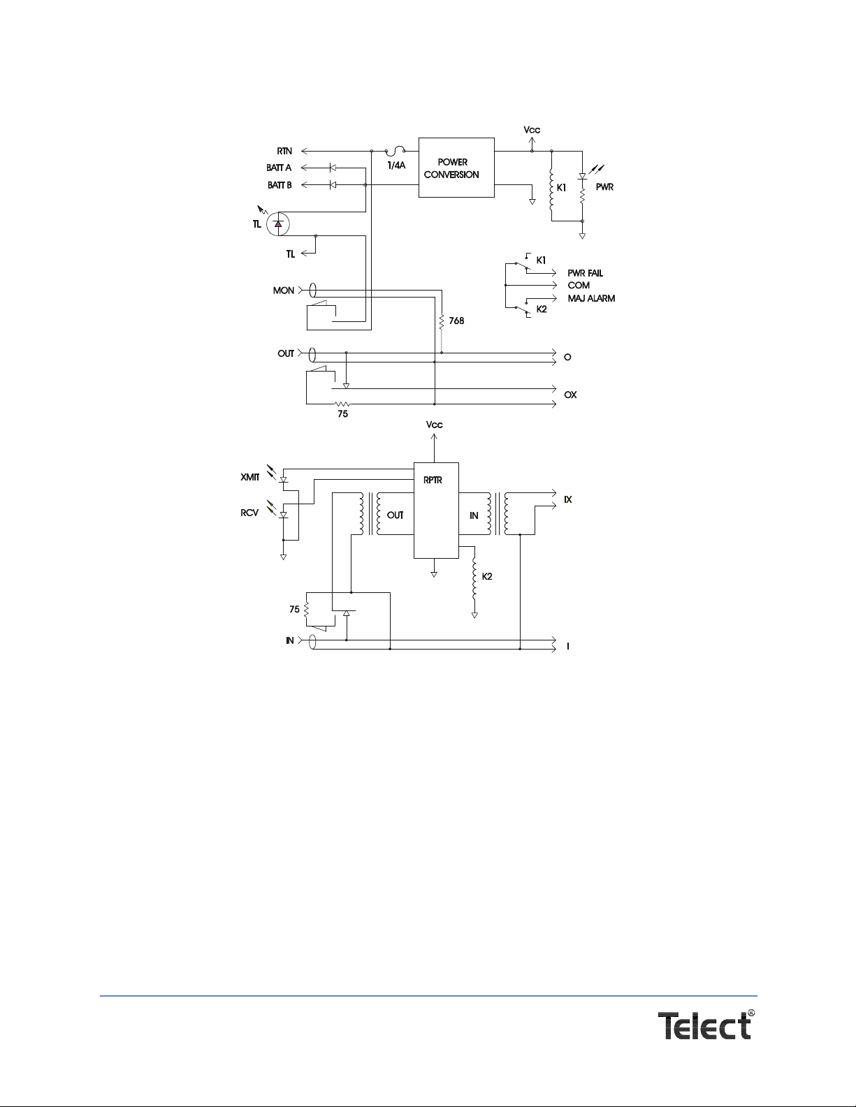
1.2 Schematic
Figure 2 - Schematic
1.3 System-Level Application
The simplex repeater regenerates DS3, E3, and STS-1 signals to equal level point over a
distance of up to 900 ft (using RG-59/734 cable). Two repeaters are required to regenerate
both the send and receive signals and complete the cross-connect.
The repeater regenerates the signal that appears on the IX port and transmits it out the I port for
a length dependent upon the type of cable used. See Section “2.1 Installation” on page 6 to set
the module jumpers based on cable length.
The OX and O ports are passive; therefore, a second repeater is required to regenerate and
transmit the signal in the other direction. Each network element can be located up to 900 ft from
the far-end repeater’s IX port.
Telect, Inc. • USA +1.509.926.6000 • Mexico +52.33.3836.37.52
www.telect.com • © 2010 Telect, Inc., All Rights Reserved, 117209-1 A0
Page 5
Page 9
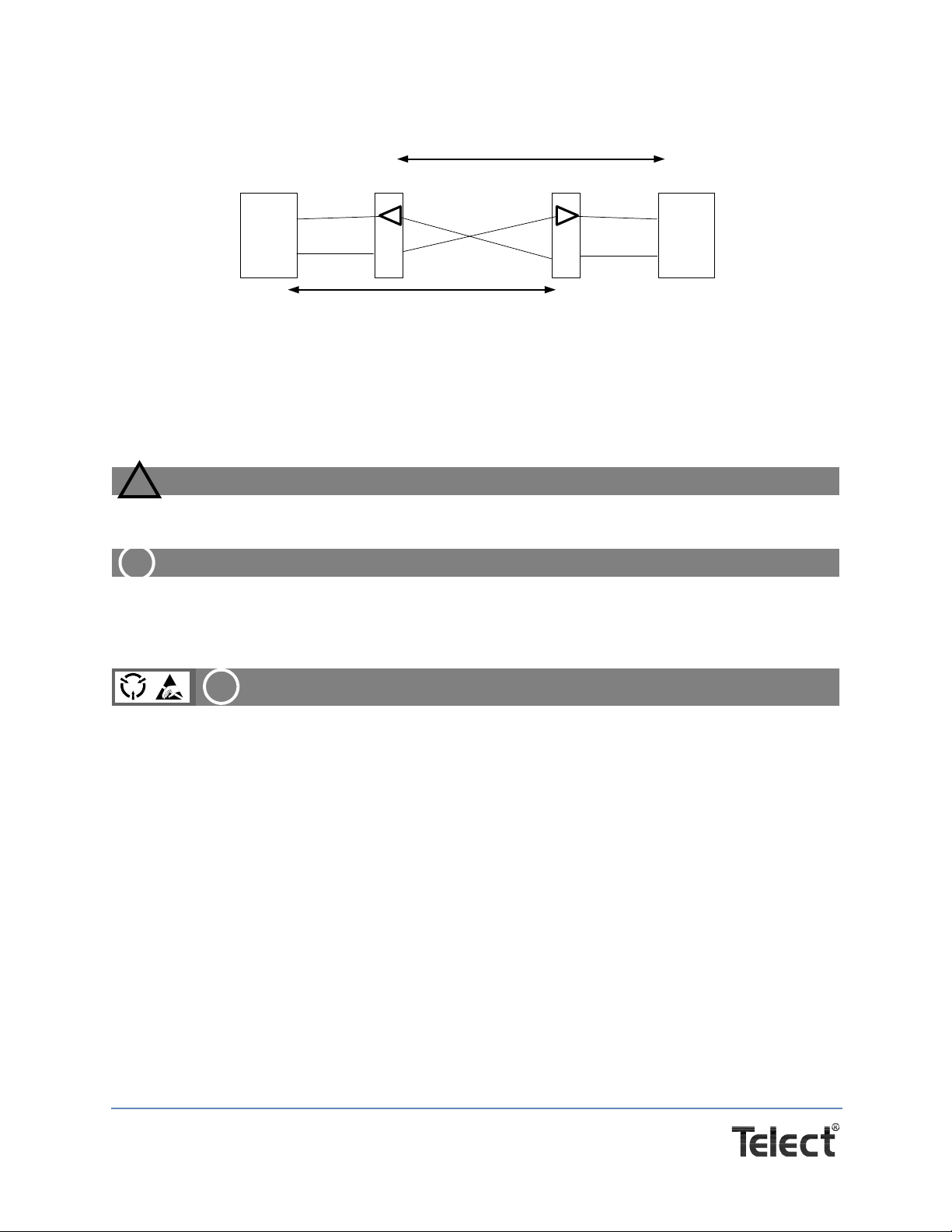
Figure 3 - Network Element Locations
CAUTION
!
ALERT
!
ALERT
!
Simplex
Repeater
I
O
IX
OX
RX
TX
Simplex
Repeater
IX
OX
I
O
NE 2
RX
TX
NE 1
Up to 900 ft (using RG-59/734)
Up to 900 ft (using RG-59/734)
2.1 Installation
2.1.1 Installation Considerations
CAUTION! Only qualified technicians may install and maintain this product.
ALERT! These instructions presume you have verified that the Telect equipment being installed is compatible with the rest of the system, including power, ground, circuit protection, signal characteristics, equipment from other vendors, and local codes or ordinances.
ALERT! This repeater module contains static-sensitive components. To prevent equipment damage, wear a properly connected grounding strap while handling the module and
store it in its original anti-static bag when not in use.
2.1.1.1 Location and Space
The BCS II Simplex Repeater module occupies one slot in any vertical BCS II chassis or in the
Vector chassis. Do not install more than five repeater modules in a BCS II chassis. The Vector
Chassis can be fully populated with repeaters. You must install two repeaters to complete the
cross-connect, one repeater for each network element.
2.1.1.2 Tools and Equipment
No special tools or equipment are required. Wear a grounding strap during installation.
Telect, Inc. • USA +1.509.926.6000 • Mexico +52.33.3836.37.52
www.telect.com • © 2010 Telect, Inc., All Rights Reserved, 117209-1 A0
Page 6
Page 10

2.1.1.3 Power
–42 Vdc to –58 Vdc power reaches the module through the backplane connector on the chassis.
Power to the backplane connector block is delivered from the power distribution panel using 16–
22 AWG wire. See the chassis user manual for additional information on power transmission.
Because the repeater is an active product, Telect recommends using a dual-feed power source.
2.1.1.4 Technical Support (USA)
By e-mail: [email protected]
By phone: 888-821-4856 or 509-921-6161
2.1.1.5 Inspection
Compare the contents of the shipping container with the packing list. Call Telect if you are
missing anything.
NOTES:
Telect is not liable for shipping damage.
If the shipping container is damaged, keep it for the carrier’s inspection. Notify the carrier and
call Telect’s Customer Service Department: 1-800-551-4567 or 1-509-926-6000.
Keep the container until you have checked equipment operation. If you experience any kind
of problem, call Telect’s Customer Service Department. Use the original, undamaged container if you are instructed to return the product to Telect.
2.2 Installing the Repeater
Procedure steps:
1. Identify the two network elements you wish to cross-connect.
2. Plan placement of the two repeater modules in relay racks, ensuring that
− The distance between the network element and the repeater is correct for the system, ca-
bles in use and office procedures. This can be up to 450 feet.
− The two repeater modules will not be more than 900 feet apart.
3. While wearing a grounding strap, remove the repeaters from their anti-static bags, touching
the module edges only.
4. Set the jumpers on each module for the appropriate data rate, as shown below. (Factory setting is T3.)
Telect, Inc. • USA +1.509.926.6000 • Mexico +52.33.3836.37.52
www.telect.com • © 2010 Telect, Inc., All Rights Reserved, 117209-1 A0
Page 7
Page 11
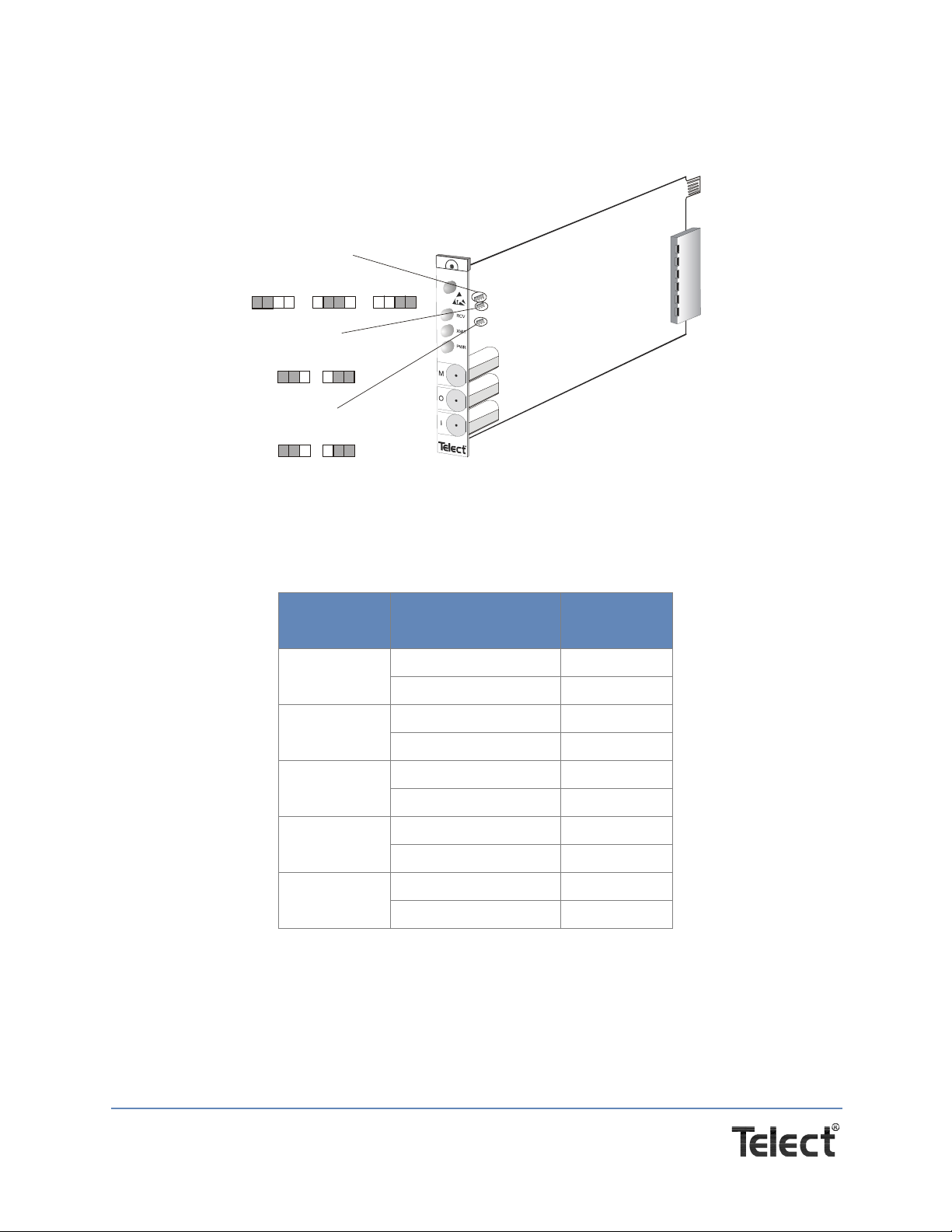
5. Set the jumpers for the transmit and receive distances, as shown below. (Factory settings are
Jumper Settings
Data Rate
T3 (DS3)
(Default)
1
324
STS-1
1324
E3
1
324
Transmit
Low
(Default)
132
High
132
Receive
Short
(Default)
132
Long
132
Low and Short.) See the tables following to determine the settings appropriate for the typ e of
cable being used.
Figure 4 - Jumper Settings
NOTE: Transmit and Receive settings are for distan ce from repeate r to network element (o r next
repeater) only.
Table 1 - Transmit Settings by Cable Type
Cable
720
728
734
735
RG-59
Repeater to NE
distance (feet)
Setting
0-124 Low
124-255 High
0-212 Low
212-425 High
0-224 Low
224-450 High
0-112 Low
112-225 High
0-224 Low
224-450 High
Telect, Inc. • USA +1.509.926.6000 • Mexico +52.33.3836.37.52
www.telect.com • © 2010 Telect, Inc., All Rights Reserved, 117209-1 A0
Page 8
Page 12

Table 2 - Receive Settings by Cable Type
Cable
720
728
734
735
RG-59
Cross-connect
distance (feet)
0-124 Short
124-255 Long
0-212 Short
212-425 Long
0-224 Short
224-450 Long
0-112 Short
112-225 Long
0-224 Short
224-450 Long
Setting
6. Slide each module into the appropriate chassis slot and press it firmly into the
backplane connector.
7. Secure each module with the included screw.
Telect, Inc. • USA +1.509.926.6000 • Mexico +52.33.3836.37.52
www.telect.com • © 2010 Telect, Inc., All Rights Reserved, 117209-1 A0
Page 9
Page 13
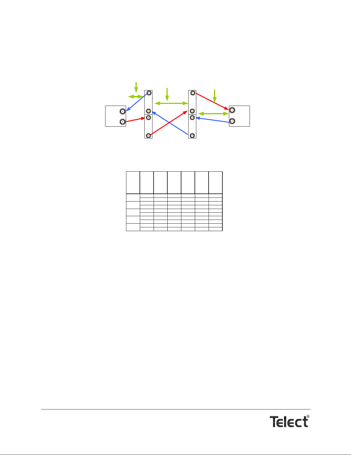
8. Follow the diagram below to connect two network elements.
Simplex Repeater
LBO Settings
CABLE
to NE
distance
(feet)
FIGURE
Distance
Transmit
LBO
Setting
to
distance
(feet)
FIGURE
Distance
Rece ive
LBO
Setting
0-124 A or C SHORT 0-124 B SHORT
124-255 A or C LONG 124-255 B LONG
0-212 A or C SHORT 0-212 B SHORT
212-425 A or C LONG 212-425 B LONG
0-224 A or C SHORT 0-224 B SHORT
224-450 A or C LONG 224-450 B LONG
0-112 A or C SHORT 0-112 B SHORT
112-225 A or C LONG 112-225 B LONG
0-224 A or C SHORT 0-224 B SHORT
224-450 A or C LONG 224-450 B LONG
RG-59
720
728
734
735
NE
NE
TX
RX
TX
RX
SIMPLEX
REPEATER
710-3201-0002
AB
Distance Distance
O
I
I
IX
OX
O
O
I
O
I
OX
IX
SIMPLEX
REPEATER
710-3201-0002
Distance
C
Each network element can be located up to 900ft. from the far end repeaters IX port.
(using RG-59/734)
Repeater
Repeater
Repeater
Figure 5 - Connecting Two Network Elements
9. Install a backplane tracer lamp wire between the two repeaters and verify that both tracer
lamp LEDs light up.
10. Install designation strips and label them, using office standards.
11. Test circuits per office standards.
This procedure is complete.
Telect, Inc. • USA +1.509.926.6000 • Mexico +52.33.3836.37.52
www.telect.com • © 2010 Telect, Inc., All Rights Reserved, 117209-1 A0
Page 10
Page 14
3.1 Operation
Monitor Jack
Test
Equipment
3.1.1 Monitoring
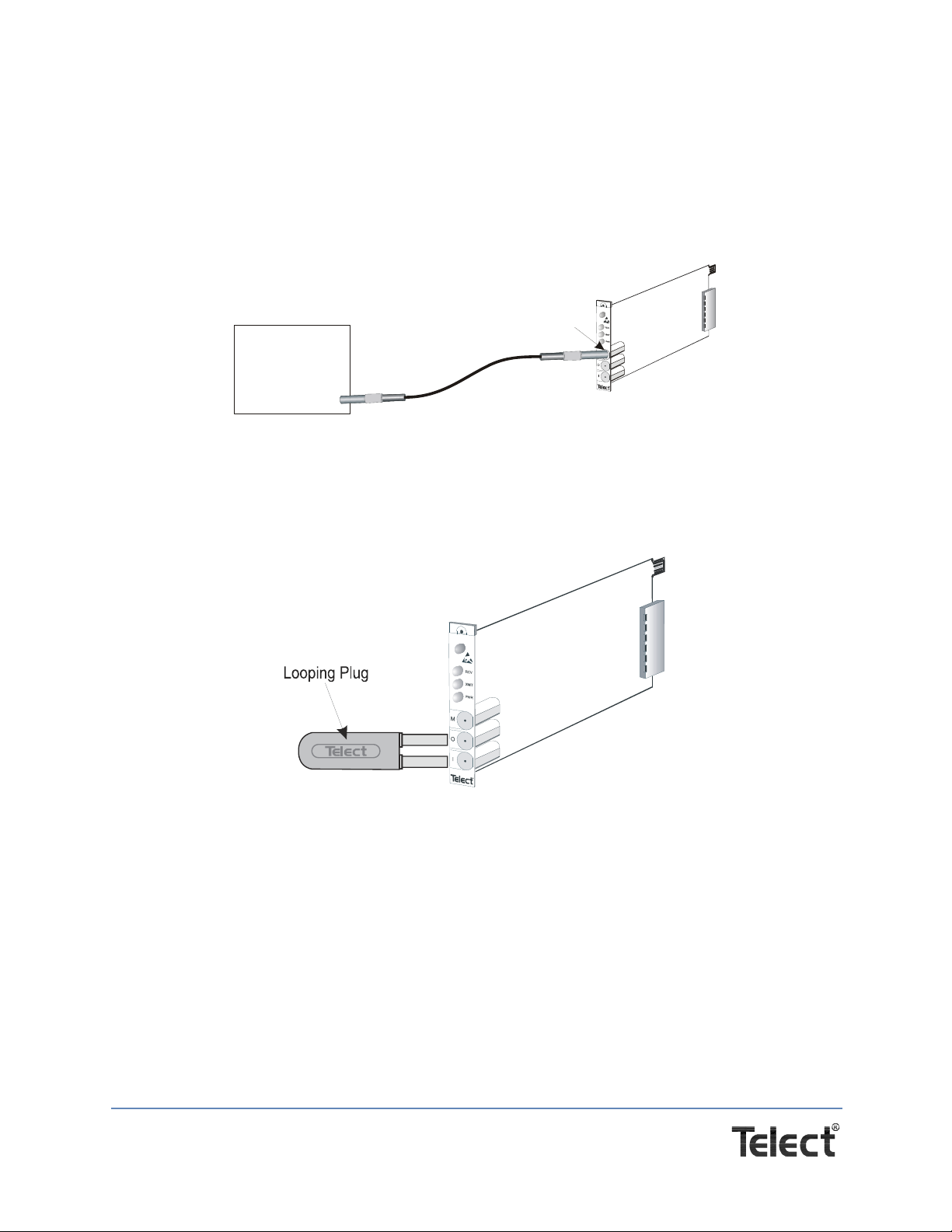
You can perform non-intrusive signal monitoring by connecting your test equipment to the front
monitor jack (labeled M).
Figure 6 - Non-intrusive Signal Monitoring
3.1.2 Loopbacks
To temporarily loop the repeater’s OUT port to its IN port, fully insert a mini-WECO looping plug
into the I/O jacks.
Figure 7 - Inserting a Mini-WECO Looping Plug
Telect, Inc. • USA +1.509.926.6000 • Mexico +52.33.3836.37.52
www.telect.com • © 2010 Telect, Inc., All Rights Reserved, 117209-1 A0
Page 11
Page 15
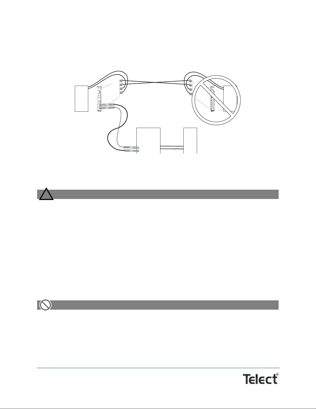
3.1.3 Patching
CAUTION
!
ALERT
Network
Element
Network
Element
Repeater
or DSX
Network
Element
OX
IX
O
I
OX
IX
O
I
Repeater Repeater
You can establish temporary patches using the I/O jacks on the front faceplate, as shown below.
This operation is intrusive and will interrupt the cross-connect, routing the signals through the
patch cords.
Figure 8 - Patching
4.1 Service
CAUTION! Only qualified technicians may install and maintain this product.
4.1.1 Owner Maintenance
Telect’s BCS II Simplex Repeater module does not need preventive maintenance. The only part
you can replace is the tracer lamp LED.
4.1.1.1 Replacing the Tracer Lamp LED
Procedure steps:
1. Pull the defective LED straight out with your fingers.
2. Align the replacement LED with the LED socket in the faceplate. Notice that the socket is
keyed, and the LED enters only one way.
ALERT! Do not bend the LED’s two metal leads.
3. Gently insert the LED into the socket, as shown on the next page. If you encounter resistance, do not force the LED into position. Move it until it slides easily into the jack module.
Telect, Inc. • USA +1.509.926.6000 • Mexico +52.33.3836.37.52
www.telect.com • © 2010 Telect, Inc., All Rights Reserved, 117209-1 A0
Page 12
Page 16
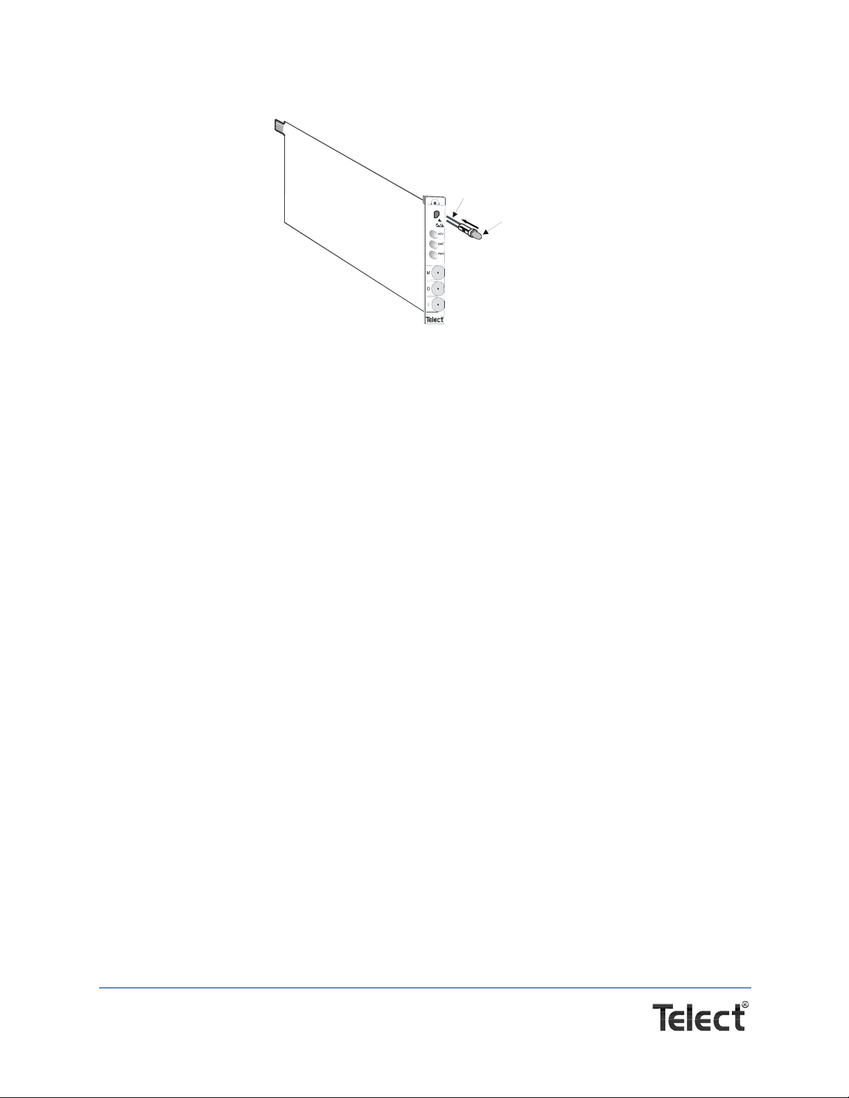
Figure 9 - Inserting the LED
Flat surface of LED to
flat surface of socket
Leads
LED
4. When the LED snaps into place, the installation is complete.
5. To test the new LED, insert a plug into the “M” (monitor) jack.
The LED flashes for about 30 seconds, then lights steadily.
This procedure is complete.
4.1.2 In Case Of Difficulty
If problems occur after initial installation, check all cable connections and the installation
instructions in Chapter 2.
4.1.2.1 Technical Support
By e-mail: [email protected]
By phone: 888-821-4856 or 509-921-6161
4.1.3 In-Warranty Service
Contact your Telect equipment distributor, or call a Telect Customer Service Representative:
1-800-551-4567
1-509-926-6000
Telect will repair or replace defective products within the limits of the warranty. See “Repacking
for Shipment” in this section.
NOTE: Call a Customer Service Represent ative for a Return Material Authorization (RMA) before
returning any equipment.
4.1.4 Out-Of-Warranty Service
The procedure for out-of-warranty service is the same as for in-warranty service, except that
Telect charges a processing fee, and you must submit a Purchase Order along with a Return
Telect, Inc. • USA +1.509.926.6000 • Mexico +52.33.3836.37.52
www.telect.com • © 2010 Telect, Inc., All Rights Reserved, 117209-1 A0
Page 13
Page 17

Material Authorization (RMA) before returning equipment. Call a Customer Service
Representative for help getting these forms.
The processing fee guarantees a repair estimate and is credited against actual material and
labor costs.
4.1.5 Repacking For Shipment
1. Tag the equipment with owner’s name, address, and telephone number, together with a
detailed description of the problem.
2. Use the original shipping container if possible. If you do not have it, p ackage the equipment in
a way to prevent shipping damage. Include the RMA inside the container and legibly print the
RMA number on the outside of the package, near the shipping address.
3. Insure the package.
NOTE: Telect is not liable for shipping damage.
Telect, Inc. • USA +1.509.926.6000 • Mexico +52.33.3836.37.52
www.telect.com • © 2010 Telect, Inc., All Rights Reserved, 117209-1 A0
Page 14
 Loading...