

Page 1

Version 2.3
D Türstationen a / b Serie 20 / 30 / 40 / 50 / 20-0028A/-0028B Seite ...... 3
GB Manual Door Intercom Devices a / b series 20 / 30 / 40/ 50 /
20-0028A/-0028B Page .....49
FR Por tiers téléphoniques a/b Séries 20 / 30 /40 / 50 /
20-0028A/-0028B Page .....86
Page 2
Anleitung Türstationen a / b Serie 20 / 30 / 40 / 50 / 20-0028A/-0028B
D
Kontakt
Wichtige Hinweise
Bitte beachten Sie, dass Behnke Sprechstellen und Zubehörteile ausschließlich von ausgebildeten Elektro-, Informations-, Telekommunika tionsfachkräften unter Einhaltung der einschlägigen
Normen und Regeln installiert und gewartet werden dürfen. Achten Sie bitte darauf, dass die Geräte
vor Wartungs- oder Reparaturarbeiten vom Stromnetz (Steckernetzteil) und vom Netzwerk bzw.
Telefonanschluss getrennt sind und die einschlägigen Sicherheitsregeln eingehalten werden.
Weitere rechtliche Hinweise finden Sie auf Seite 45.
Info-Hotline
Ausführliche Informationen zu Produkten,
Projekten und unseren Dienstleistungen:
Tel.: +49 (0) 68 41 /81 77-700
24 h Service-Hotline
Sie brauchen Hilfe? Wir sind 24 Stunden
für Sie da und beraten Sie in allen tech nischen Fragen und geben Starthilfen:
Tel.: +49 (0) 68 41 /81 77-777
Telecom Behnke GmbH
Gewerbepark „An der Autobahn“
Robert-Jungk-Straße 3
66459 Kirkel
E-Mail- und Internet-Adresse
[email protected]
www.behnke-online.de
2 www.behnke-online.de
Page 3

Anleitung Türstationen a / b Serie 20 / 30 / 40 / 50 / 20-0028A/-0028B
Inhalt
1. Einleitung 6
1.1. Allgemeines .................................................................................................................... 6
2. Montage 8
2.1. Seri e 20 / 30 / 4 0 / 50 (20 -0001/-0002/-00 10/-0013/-0014/-00 16/-0041/-00 43) ...............8
2.2. Mechanische Montage Serie 20/30 .............................................................................. 10
2.3. Beschriftetes Etikett einlegen .......................................................................................13
2.4. Universalgeräte 20-0005/-0006/-0018/-0026/-0028A/-0028B/-0048 ..........................14
2.5. Serie 50 .........................................................................................................................14
3. Anschluss 15
Serie 20 / 30 / 40 / 50 und 20-0005/-0006/-0018/-0026/-0028A/-0028B/-0048 ..............15
▸
3.1. Anschlusspläne .............................................................................................................16
Kompaktelektronik 20-0001/-0002/-0010*/-0013/-0014/-0016/-0041/-0043 ...................16
▸
Universalelektronik 20-0005 .........................................................................................17
▸
Universalelektronik 20-0006/-0018/-0026 (bis 4. Quartal 2018) ..................................... 18
▸
Universalelektronik 20-0006/-0018/-0026 (ab 1. Quartal 2019) ...................................... 19
▸
Universalelektronik 20-0048 (bis 4.Quartal 2018) ..........................................................20
▸
Universalelektronik 20-0048 (ab 1. Quartal 2019) ............................................................21
▸
Aufzugnotrufsprechstelle 20-0028A
▸
(bis Firmwarestand BT MA 1.63, ausgeliefert bis 3. Quartal 2018) ..................................... 22
Aufzugnotrufsprechstelle 20-0028A
▸
(bis Firmwarestand BT MA 1.63, ausgeliefert bis 2. Quartal 2019 ) .................................... 24
Aufzugnotrufsprechstelle 20-0028B
▸
(ab Firmwarestand BT MA 1.64, ab 2. Quartal 2019) ........................................................26
D
4. Konfiguration 28
5. Bedienung 38
6. Erweiterte Bedienung 39
6.1. Steuerungsmöglichkeiten während Sprachverbindungen ............................................. 39
6.2. Automatische Akustik-Einstellung mit ##*-Funktion (ab V1.51) ......................................41
6.3. Rufannahme bei aktivierter Wahlwiederholung / Sammelruf
(Konfigurationsschritt 20 aktiv) .......................................................................................... 42
7. Fehlertabelle 43
8. FAQ 44
9. Technische Daten 46
10. Rechtliche Hinweise 47
3www.behnke-online.de
Page 4

Anleitung Türstationen a / b Serie 20 / 30 / 40 / 50 / 20-0028A/-0028B
D
Einleitung
.
1.1. Allgemeines
Bitte beachten Sie bei der Installation und
Konfiguration Ihrer Türstation folgende Eigenschaften:
Betrieb an einer analogen Nebenstelle einer
▸
Telefonanlage, einem analogen Hauptanschluss oder sonstigen a / b-Schnittstellen.
Hinweis: Bitte achten Sie beim Einsatz
sonstiger a / b-Schnittstellen darauf, dass sie
die entsprechenden Vorgaben einer analogen
Nebenstellen, wie Besetzton, MFV-Transparenz etc. erfüllen.
Betrieb ohne zusätzliche Spannungsver-
▸
sorgung möglich
Die Türstationen arbeiten im Vollduplexmo-
▸
dus, umschaltbar auf Semiduplex und Simplex (ggf. Zusatzversorgung notwendig).
Einbaubedingungen
Die optimale Einbauhöhe liegt vor, wenn die
▸
Bedienung der Türstation mit einem Abstand
von 30-50 cm gewährleistet ist und eine
stehende Person bequem in das Mikrofon
sprechen kann.
Bitte halten Sie den Abstand zwischen Mikro-
▸
fon und Lautsprecher größtmöglich. So erhalten Sie eine bestmögliche Sprachverständigung im Vollduplexmodus.
Sorgen Sie bei Hinterbaumodulen (= Montage
▸
hinter einer vorhandener Frontwand) für genügend große Schalleintrittsschlitze vor dem
Mikrofon und Schallaustrittsschlitze vor dem
Lautsprecher (mindestens 75% der Lautsprechermembranfläche für Schallaustritt bzw.
75% der Schalleintrittsöffnung am Mikrofon-
gehäuse). Siehe auch Maßzeichnungen unter
www.behnke-online.de/downloads
Montieren Sie die Hinterbaumodule aus akus-
▸
tischen Gründen immer flächenbündig (ohne
Abstand) hinter Ihrer Frontwand und verwenden Sie unbedingt die mitgelieferte Dichtung
zwischen Frontwand und Einbaumodul.
Montage im Außenbereich
Türstationen der Serie 20 und 30 sollten
▸
beim Einsatz an Wetterseiten mit einer
Regenschutzblende bei der Unterputzmontage oder einem Aufputz-Gehäuse bei der
Aufputzmontage eingebaut werden (Achten
Sie bitte immer auf den korrekten Einbau der
mitgelieferten Dichtung.).
Dichten Sie bei der Unterputzmontage den
▸
oberen Rand der Türstation zum Schutz gegen
Regenwasser gut ab, insbesondere bei einem
unebenen Untergrund (z.B. mit Silikon). Die
Mitte des unteren Rands der Türstation lassen
Sie bitte als Wasserablaufschlitz frei. Beim
Einsatz von Abdeckblenden ist die Abdeckblende mit einer passenden Dichtmasse
gegen das Unterputzgehäuse bzw. die plane
Fläche bei Hohlwandmontagen abzudichten.
Bei Einbau in Fremdstelen muss durch geeig-
▸
nete Maßnahmen die Kondensatbildung in
der Stele verhindert werden.
Dichtungen
Zum Schutz vor Feuchtigkeit achten Sie bitte
beim Einbau Ihrer Türstation auf den korrekten
Sitz der mitgelieferten Dichtungen. Die Dichtung
muss sauber auf dem Rahmen des Unter- oder
Aufputzgehäuses aufliegen! Unterputzgehäuse
sind zum Einbau in Mauerwerk oder Gipskartonplatten. Sie finden darin die wichtigsten
4 www.behnke-online.de
Page 5

Anleitung Türstationen a / b Serie 20 / 30 / 40 / 50 / 20-0028A/-0028B
Einleitung
D
Einbauhinweise eingeklebt.
Bestellen Sie bitte zur Montage in Gipskartonplatten das Montageset (Best.-Nr.: 20-5216) mit.
Entfernung der Elektronik zu Tasten,
Lautsprecher und Mikrofon (Achtung nur mit
den nachfolgenden Elektroniken möglich)
20-0005: max. 25 m
▸
20-0006/-0018/-0026/-0028A/-0028B und
▸
20-0048: Bei einer Taste max. 25 m, bei zwei
Tasten 12,5 m, bei drei Tasten 8,5 m*
*Bei Leitungslängen größer der oben genannten
Längen kann eine Basiselektronik 40-0006
(Triphonie) eingesetzt werden.
Verkabelung bei entfernt abgesetzten
Montagen (20-0005/-0006/-0018/-0026/
-0028A/-0028B/-0048)
Verwenden Sie bei der Montage Behnke
▸
Patchkabel oder geschirmte Leitungen, z.B.
IY-ST-Y oder AY-ST-Y und schließen Sie den
Schirm der Leitung an der Klemme 12 V– an
der Türstation an (nicht an Erde).
Hinweis: Führen Sie den Kabelschirm im
Bereich der Frontblende möglichst nah an
Lautsprecher, Mikrofon und Taste und isolie-
ren Sie ihn dort.
Original Behnke Teile
Setzen Sie bitte ausschließlich Behnke Teile als
Zubehör oder Ersatzteil ein – dies gilt auch für
Steckernetzteile! Nur so ist ein störungsfreier
Betrieb gewährleistet. Elektroniken nur in den
gelieferten Gehäusen einbauen bzw. verbauen.
Bei der Montage in Fremdgehäusen oder ohne
die gelieferten Gehäuse keine Gewährleistung
auf Funktion und Zulassung.
Konfiguration
Die Türstationen können lokal an der Basiselektronik oder aus der Ferne per Telefon (MFV-/
DTMF-Signal = Tonwahl) konfiguriert werden.
Alle Türstationen werden bereits vorkonfiguriert
mit einer Standardkonfiguration ausgeliefert.
Vorschriften
Bitte beachten Sie die einschlägigen Vorschriften für die Installation von Fernmelde-und
Elektroanlagen!
Reinigung und Pflege
Sie haben hochwertige Behnke Produkte mit
Frontblenden aus verschiedenen Materialien
verbaut. Für alle Materialien gilt, dass diese
in regelmäßigen ausreichend kleinen Abständen, dem Material entsprechend, mit einem
passenden Reinigungsmittel zu reinigen sind.
Somit wird eine vorzeitige Alterung und
sonstige Patina Bildung auf den Oberflächen
verhindert.
5www.behnke-online.de
Page 6

Anleitung Türstationen a / b Serie 20 / 30 / 40 / 50 / 20-0028A/-0028B
D
Montage
.
Hinweis: Bemaßungs- und Einbauskizzen finden Sie unter www.behnke-online.de/bemassung
2.1. Serie 20 / 30 / 40 / 50 (20-0001/-0002/-0010/-0013/-0014/-0016/-0041/-0043)
Hinweis: Achten Sie beim Einsetzen der
Funktionsmodule aus optischen Gründen und
zum Feuchtigkeitsschutz bitte auf die Richtung der Alu-Bürstungund beachten Sie den
Verdrehschutz der Module! Die Türstation darf
nur mit passendem Rahmen montiert werden.
Verhindern Sie Kondensatbildung im Geräteinnern! Montieren Sie die Türstation so, dass kein
Wasser auf der Frontblende stehen bleiben
kann. Legen Sie bei der Montage in Säulen
anderer Hersteller ein besonderes Augenmerk
auf die Be- und Entlüftung der Säule.
Bei einer räumlich lokal abgesetzten Montage
der Elektronik wird das Modulgehäuse durch
eine offene Gegenplatte für den entsprechenden Frontrahmen ersetzt (Tastenverlängerung
20-9305 benutzen, Anschlussleitungen nicht
selbstständig verlängern, max. 3 m).
Leitungen in der folgenden Reihenfolge
verbinden:
1. Tasten (RT) ▸ an die mit dem gelben Ring
gekennzeichneten MQS-Stecker von T1 bis T8
anschließen
T1 (Taste 1)= Konfigurationsschritt 21
...
T8 (Taste 8)= Konfigurationsschritt 28
Bei Anschluss von Fremdtastern ist darauf zu
achten, dass die Taster den entsprechenden
Zulassungsbestimmungen entsprechen.
„Klingel taster“ tun dies in der Regel nicht. (s.
Seite 11 ) Taster müssen potenzialfrei sein.
2. Lautsprecher (LP) ▸ an den mit dem blauen
Ring gekennzeichneten Stecker aufstecken
3. Mikrofon (Mik) ▸ an den mit dem weißen
Ring gekennzeichneten Stecker aufstecken
4. Tastwahlblock
5. Kamera
6. Schließen Sie bei Bedarf den Türöffner an
▸
signal FBAS)
Relais 1 an. (Relais = spannungsfreier Kontakt: schaltet nur den Türöffnerstromkreis,
versorgt ihn nicht mit elektrischer Spannung.
Nutzen Sie dazu bitte den Schließerkontakt).
Der Türöffner benötigt einen eigenen Stromkreis. Relais 2 steht für weitere Schaltfunktionen zur Verfügung.
12-polige weiße Buchse
▸
4-polige schwarze Buchse (Video-
6 www.behnke-online.de
Page 7

Anleitung Türstationen a / b Serie 20 / 30 / 40 / 50 / 20-0028A/-0028B
7. Schließen Sie, falls nötig, 12-15 V= an
(potentialfrei; Behnke Steckernetzteil 20-9585
benutzen). Ist erforderlich für Beleuchtung,
integrierte Heizung und Zusatzverstärker;
nicht erforderlich für Telefonbetrieb inkl. aller
Funktionen. Sonder funktionen wie Kamera,
Display, Sprachansagen, Zeitsteuerung benö-
tigen ggf. Zusatzelektroniken sowie auch die
Zusatzversorgung. Bei mehreren Türstationen
sorgen Sie bitte immer für eine galvanische
Trennung der Zusatzversorgung. Hinweis:
Es dürfen nicht mehrere Geräte parallel mit
einem Netzteil ohne DC/DC-Wandler betrie-
ben werden.
8. Schließen Sie die Telefonleitung an:
a / b-Leitung von analoger Nebenstelle einer
Telefonanlage, analogem Hauptanschluss
oder sonstigen a / b-Schnittstellen. Nach dem
Anschließen der Telefonleitung hören Sie
einen langen Piepton, der die Betriebsbereit-
schaft der Türstation signalisiert (=Initialisie-
rung). Die Türstation ist jetzt zur Konfiguration
bereit. Hinweis: Die Geräte dürfen nicht paral-
lel an einer a/b-Leitung betrieben werden.
Montage
D
Verlegen Sie die nicht benutzten Leitungen
bitte im Modulgehäuse mit dem offenen Ende
(Stecker) nach unten. Dies verhindert, dass
Feuchtigkeit in den Stecker eindringen kann.
Setzen Sie danach die Elektronikbox auf das
Modulgehäuse auf.
7www.behnke-online.de
Page 8
Anleitung Türstationen a / b Serie 20 / 30 / 40 / 50 / 20-0028A/-0028B
D
Montage
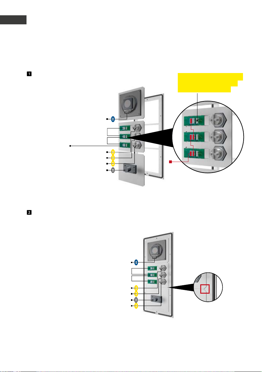
2.2. Mechanische Montage Serie 20/30
Funktionsmodule in Frontrahmen einlegen
LP
Brücken
Beleuchtung 12 V=
(Leitung kommend von der
Basiselektronik)
Legen Sie die Module rückseitig in den Rahmen ein.
RT
RT
RT
Mik
T
T
T
Anschluss Tastenbeleuchtung
Behnke Taster (beleuchtete
Tasten optional möglich)
Beleuchtung 12 V=
12 V-Brücken zur Beleuchtung
der Beschriftungsfelder
Funktionsmodule in Frontrahmen
LP
RT
T
RT
T
Mik
RT
T
Achten Sie beim Einlegen der Module bitte unbedingt auf den Verdrehschutz und achten Sie außerdem darauf, dass die Module mit einem hörbaren "Klick" einrasten.
8 www.behnke-online.de
Page 9
Anleitung Türstationen a / b Serie 20 / 30 / 40 / 50 / 20-0028A/-0028B
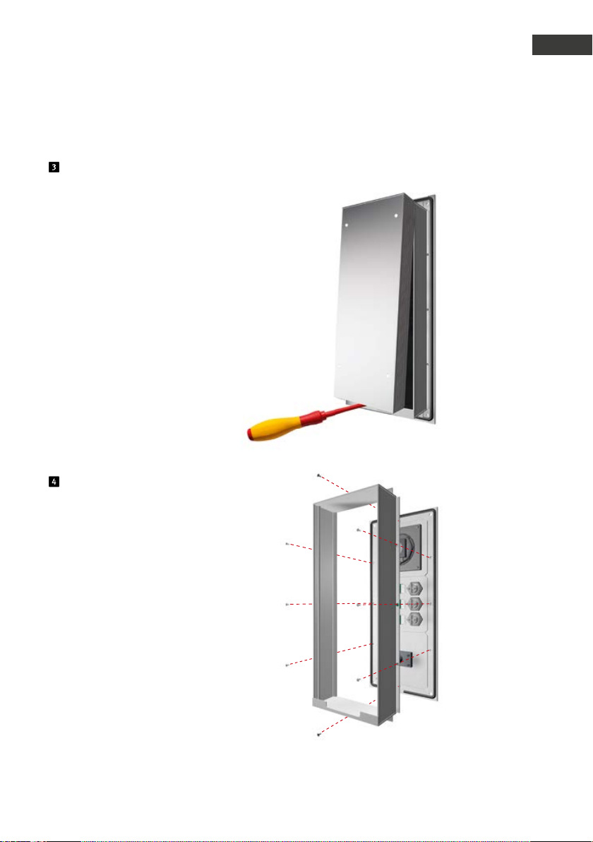
Elektronikbox vom Modulgehäuse entfernen
Montage
D
Modulgehäuse befestigen
*
bei abgesetzter Montage mit offener Gegenplatte verschrauben.
*
9www.behnke-online.de
Page 10
Anleitung Türstationen a / b Serie 20 / 30 / 40 / 50 / 20-0028A/-0028B
D
Montage
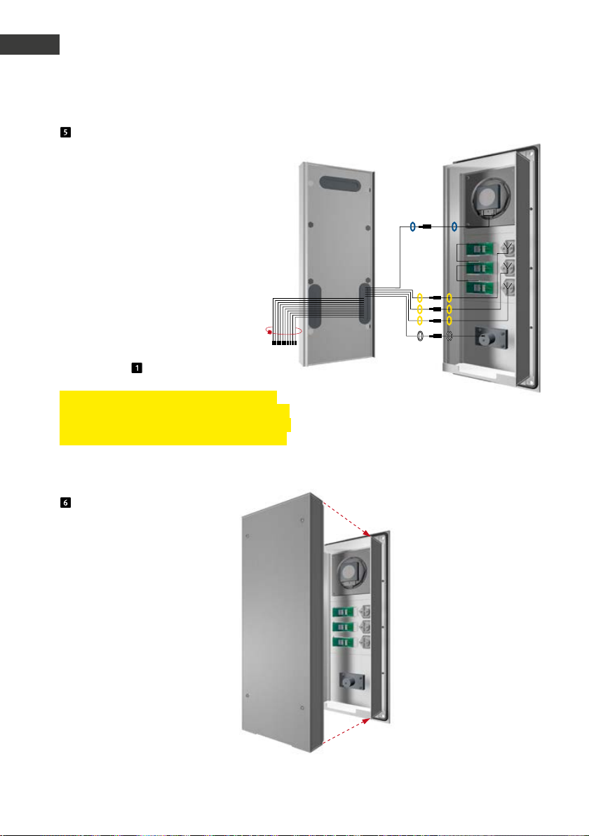
Verbinden der Flachbandanschlussleitung
mit den Einbaumodulen (Lautsprecher, Mikrofon,
Tasten etc.)
Steckerbelegung Anschlussleitung
Serie 20, 30, 50:
LP (Blau) ▸ Lautsprecher
Mik (Weiß) ▸ Mikrofon
T1 bis T8 (Gelb) ▸ Taste 1 bis 8
12-poliger Stecker ▸ Tastwahlblock
HPI Kontakt (Weiß) ▸ Beschriftungsfeld
(s. auch Punkt )
Hinweis: Verbinden Sie die vorhandene Komponenten mit der Flachbandleitung. Binden Sie
die nicht benötigten Leitungen mit einem Kabelbinder zusammen (Stecker zeigen nach unten).
Elektronikbox
T1
T2
T3
T
T
T
Modulgehäuse
Klipsen Sie die Elektronikbox
wieder auf das Modulgehäuse auf.
10 www.behnke-online.de
Page 11
Anleitung Türstationen a / b Serie 20 / 30 / 40 / 50 / 20-0028A/-0028B
Montage
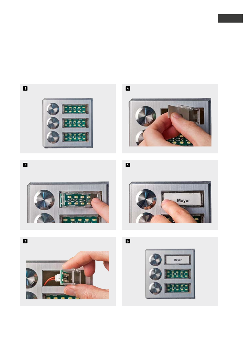
2.3.
Beschriftetes Etikett einlegen
Etiketten im Lieferumfang der Basiselektronik enthalten. Beschriftungssoftware siehe unter:
www.behnke-online.de/downloads/beschriftungshilfen
D
Auslieferungszustand
Beschriftungsfeld durch Druck
auf die rechte Seite lösen
und herausdrehen
Das beschriftete Etikett von links einlegen
Das Beschriftungsfeld links anlegen und
einrasten lassen
Fertig!
11www.behnke-online.de
Page 12
Anleitung Türstationen a / b Serie 20 / 30 / 40 / 50 / 20-0028A/-0028B
D
Montage
2.4. Universalgeräte 20-0005/-0006/
-0018/-0026/-0028A/-0028B/-0048
1. Montieren Sie die Universalelektronik an
einem wettergeschützten Ort im gelieferten
Gehäuse und verbinden Sie die Elektronik mit
der oder den Bedieneinheit(en).
2. Beachten Sie bitte die Hinweise zur Ver-
kabelung, Entfernungen und Leitungslängen
auf Seite 5.
3. Angeschlossene Tasten müssen die Erforder-
nisse der EN60950 für Telefonstromkreise
(TNV) erfüllen. Normale „Klingeltaster“ erfüllen diese Anforderungen in der Regel nicht;
verwenden Sie ggf. Behnke Tasten!
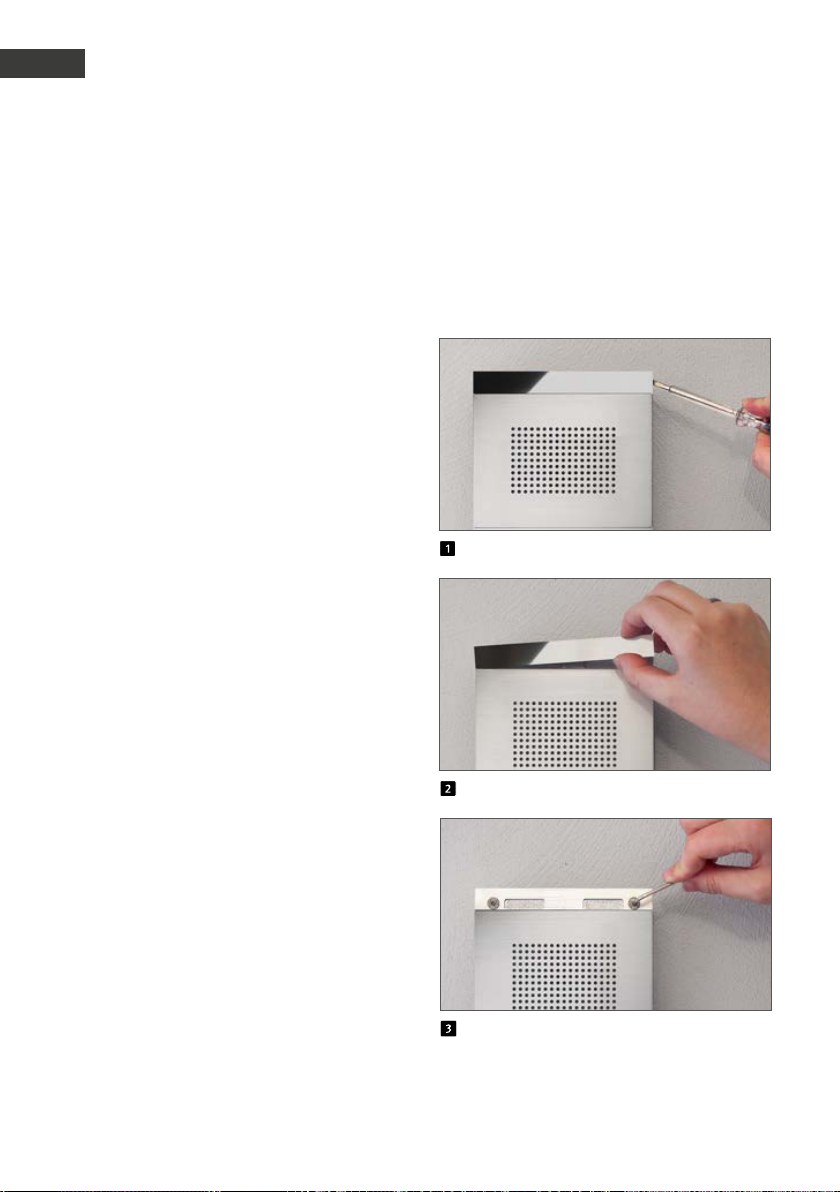
2.5. Serie 50
Türstationen der Serie 50 werden bereits
montiert geliefert. Gehen Sie bitte beim Einbau
wie hier gezeigt vor. Hinweise zur elektrischen
Montage finden Sie auf den folgenden Seiten.
Edelstahlstreifen abklipsen
Edelstahlstreifen entfernen
Türstation anschließen und befestigen
12 www.behnke-online.de
Page 13

Anleitung Türstationen a / b Serie 20 / 30 / 40 / 50 / 20-0028A/-0028B
.
Serie 20 / 30 / 40 / 50 und 20-0005/-0006/
-0018/-0026/-0028A/-0028B/-0048
Anschluss
D
Hinweis zum Anschluss von 20-0005/-0006/
-0018/-0026/-0028A/-0028B/-0048:
Beginnen Sie bitte mit dem Anschließen von
Lautsprecher, Mikrofon und Tasten und achten
Sie dabei auf einen max. Abstand zwischen
Lautsprecher, Mikrofon, den Tasten und der
Elektronik. Beachten Sie die Hinweise zur
Verkabelung, Entfernungen und Leitungslängen
ab Seite 5. Achtung: Tasten dürfen keine
gemeinsame Rückleitung (Masse) haben!
1. Schließen Sie bei Bedarf den Türöffner an
Relais 1 an. Relais = spannungsfreier Kontakt;
schaltet nur den Türöffnerstromkreis, versorgt
ihn nicht mit elektrischer Spannung (Schließerkontakt benutzen). Der Türöffner benötigt
einen eigenen Stromkreis. Relais 2 steht für
weitere Schaltfunktionen zur Verfügung.
2. Schließen Sie, falls nötig, 12-15 V= an (poten-
tialfrei – Behnke Steckernetzteil 20-9585
benutzen: Erforderlich für Beleuchtung, integrierte Heizung, integrierten Zusatzverstärker;
nicht erforderlich für Telefonbetrieb inkl. aller
Funktionen. Sonderfunktionen wie Kamera,
Display, Sprachansagen, Zeitsteuerung benötigen gegenfalls. Zusatzelektroniken sowie
auch die Zusatzversorgung. Sorgen Sie bei
mehreren Türstationen bitte immer für eine
galvanische Trennung der Zusatzversorgung.
Hinweis: Die Geräte dürfen nicht parallel mit
ihrer Zusatzversorgung betrieben werden.
3. Schließen Sie die Telefonleitung an:
a / b-Leitung von analoger Nebenstelle einer
Telefonanlage, analogem Hauptanschluss
oder sonstigen a / b-Schnittstellen. Nach dem
Anschließen der Telefonleitung hören Sie
einen langen Piepton, der die Betriebsbereitschaft der Türstation signalisiert (=Initialisierung). Die Türstation ist jetzt zur Konfiguration
bereit. Hinweis: Die Geräte dürfen nicht parallel an einer a / b-Leitung betrieben werden.
13www.behnke-online.de
Page 14
Anleitung Türstationen a / b Serie 20 / 30 / 40 / 50 / 20-0028A/-0028B
D
Anschluss
Hinweis: Weitere Konfigurationsschritte
finden Sie ab Seite 26.
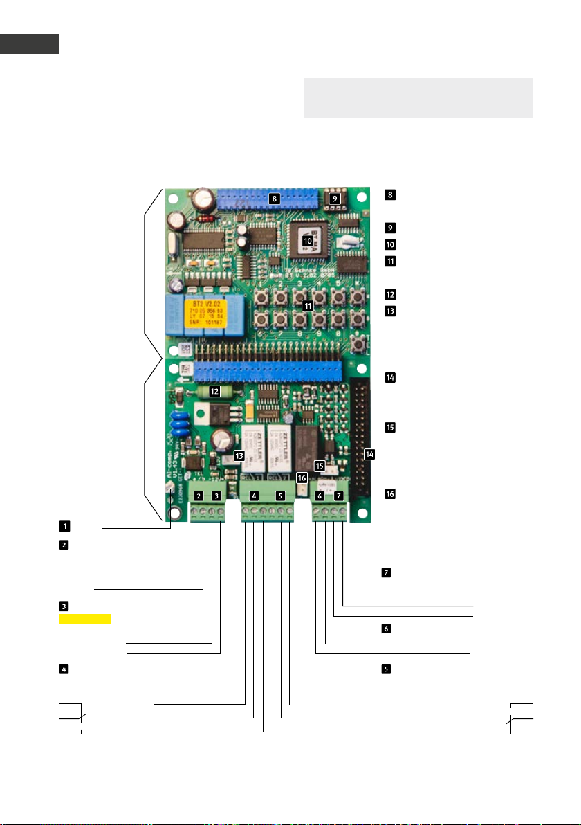
3.1. Anschlusspläne
Kompaktelektronik 20-0001/-0002/-0010*/-0013/-0014/-0016/-0041/-0043
Hauptplatine
Anschlussplatine
Erde
Telefonleitung
Analoger Hauptsanschluss oder
Nebenstelle einer Telefonanlage
a-Ader
b-Ader
Zusatzversorgung
potentialfreie Spannung
z. B. von B ehnke Stecker netzteil
12 - 15 V =
Relais 1
Relaisschaltleistung: max. 60 VA 24 W
0,5 A 120 V~ oder 1A 24V=
–
+
Ruhekontakt Arbeitskontakt
Steuerkontakt Steuerkontakt
Arbeitskontakt Ruhekontakt
nur beschaltet mit eine m Modul
mit Kamera
Relaisschaltleistung: max. 60 VA 24 W 0,5
A 120 V~ oder 1A 24V=
Anschluss für
Zusatzplatinen
EEprom
Masterprozessor
Interne Konfigurations-
tastatur
Heizwiderstand
Anschlussstecker für
Beleuchtung (nur erfor-
derlich für Module mit
Beleuchtung)
Flachbandleitung zum
An-schluss der Module mit
Tasten, LS, Mikrofon usw.
Alarmeingang nur zur An-
schaltung einer Behnke
Weitwinkel IP-Kamera mit
App-Funktionalität
Relais 2 nur zur Anschal-
tung einer Behnke
Weit-winkel IP-Kamera mit
App-Funktionalität
Videoausgang
Video-Masse
Videosignal
Alarmeingang
–
6 - 24 V =
+
Relais 2
* Anschlußstecker bei 20-0010 nicht abziehbar
14 www.behnke-online.de
Page 15
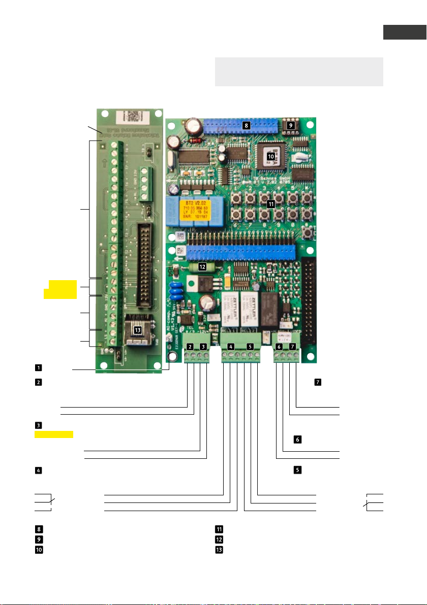
Universalelektronik 20-0005
Subplatine *
Passendes
Installations-
material zur
Adaption von Lautsprecher, Mikrofon
und Tasten
an der Tür:
Abzweigbox 20-9251
Klemmen
Taster 1 bis 8
pot. freie Tasten,
max. 25 m
Leitungslänge
(s. Seite 4)
(Konfigurations-
schritte 21 bis 28)
Mikrofon
(Polarität
beachten!)
nicht belegt
Anleitung Türstationen a / b Serie 20 / 30 / 40 / 50 / 20-0028A/-0028B
Anschluss
Hinweis: Weitere Konfigurationsschritte
finden Sie ab Seite 26.
D
Lautsprecher
Erde
Telefonleitung
Analoger Hauptsanschluss oder
Nebenstelle einer Telefonanlage
a-Ader
b-Ader
Zusatzversorgung
potentialfreie Spannung
z. B. von B ehnke Stecker netzteil
12 - 15 V =
Relais 1
Relaisschaltleistung: max. 60 VA 24 W
0,5 A 120 V~ oder 1A 24V=
–
+
Ruhekontakt
Steuerkontakt
Arbeitskontakt
Anschluss für Zusatzplatinen
EEprom
Masterprozessor
Videoausgang
nur beschaltet mit einem
Modul mit Kamera
Video-Masse
Videosignal
Alarmeingang
–
+
Relais 2
Relaisschaltleistung: max. 60 VA
24 W 0,5 A 120 V~ oder 1A 24V=
Arbeitskontakt
Steuerkontakt
Ruhekontakt
Interne Konfigurationstastatur
Heizwiderstand
Anschlussbuchse für Tastwahlblock max.
25 m Anschlussleitung 20-9308 (3 m)
6 - 24 V =
15www.behnke-online.de
Page 16
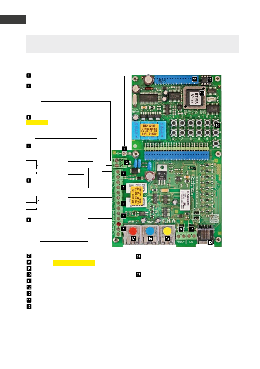
Anleitung Türstationen a / b Serie 20 / 30 / 40 / 50 / 20-0028A/-0028B
D
Anschluss
Hinweis: Bitte vergleichen Sie ihre Anschlussplatinen des gelieferten Gerätes/Rep-Kit mit den
Anschlussplatinen auf dem Foto. Weitere Konfigurationsschritte finden Sie ab Seite 26.
Universalelektronik 20-0006/-0018/-0026 (bis 4. Quartal 2018)
Erde
Telefonleitung
Analoger Hauptsanschluss oder Nebenstelle
einer Telefonanlage
a-Ader
b-Ader
Zusatzversorgung
potentialfreie Spannung z. B. von
Behnke Steckernetzteil
–
12 V - 15 V=
+
Relais 1
Relaisschaltleistung: max. 60 VA 24 W
0,5 A 120 V~ oder 1A 24V=
Ruhekontakt
Steuerkontakt
Arbeitskontakt
Relais 2
Relaisschaltleistung: max. 60 VA
24 W 0,5 A 120 V~ oder 1A 24V=
Ruhekontakt
Steuerkontakt
Arbeitskontakt
Alarmeingang
potentialfreie Spannung z. B. von
Behnke Steckernetzteil
–
6 - 24 V =
+
Taster 2 (potentialfreier Schließer)
Mikrofon (Polarität beachten)
Lautsprecher
Tastwahlblock
Anschluss für Zusatzplatinen
EEprom
MLM B (Zusatz-MLM) – Mikrofon Lautsprecher-Modul (Konfigurations schritt 23 / Taste 3)
MLM C (Zusatz-MLM) – Mikrofon Lautsprecher-Modul (Konfigurations schritt 24 / Taste 4)
Masterprozessor
Interne Konfigurationstastatur
MLM A (Haupt-MLM) – Mikrofon Lautsprecher-Modul (Konfigurations schritt 22 / Taste 2)
Hinweis: Beim Anschluss mehrerer MLMs verkürzt sich die maximale Entfernung zwischen MLM und Basiselektronik:
1 MLM = 25 m / 2 MLMs = je 12,5 m / 3 MLMs = je 8,5 m
Passendes Installationsmaterial zur Adaption von Lautsprecher, Mikrofon und Tasten an der Tür: Abzweigbox 20-9208
alternativ Patchkabel 20-9309
Konfiguration der Rufnummern
Gelb: Konfigurationsschritt 22
Blau: Konfigurationsschritt 23
Rot: Konfigurationsschritt 24
16 www.behnke-o nline.de
Page 17
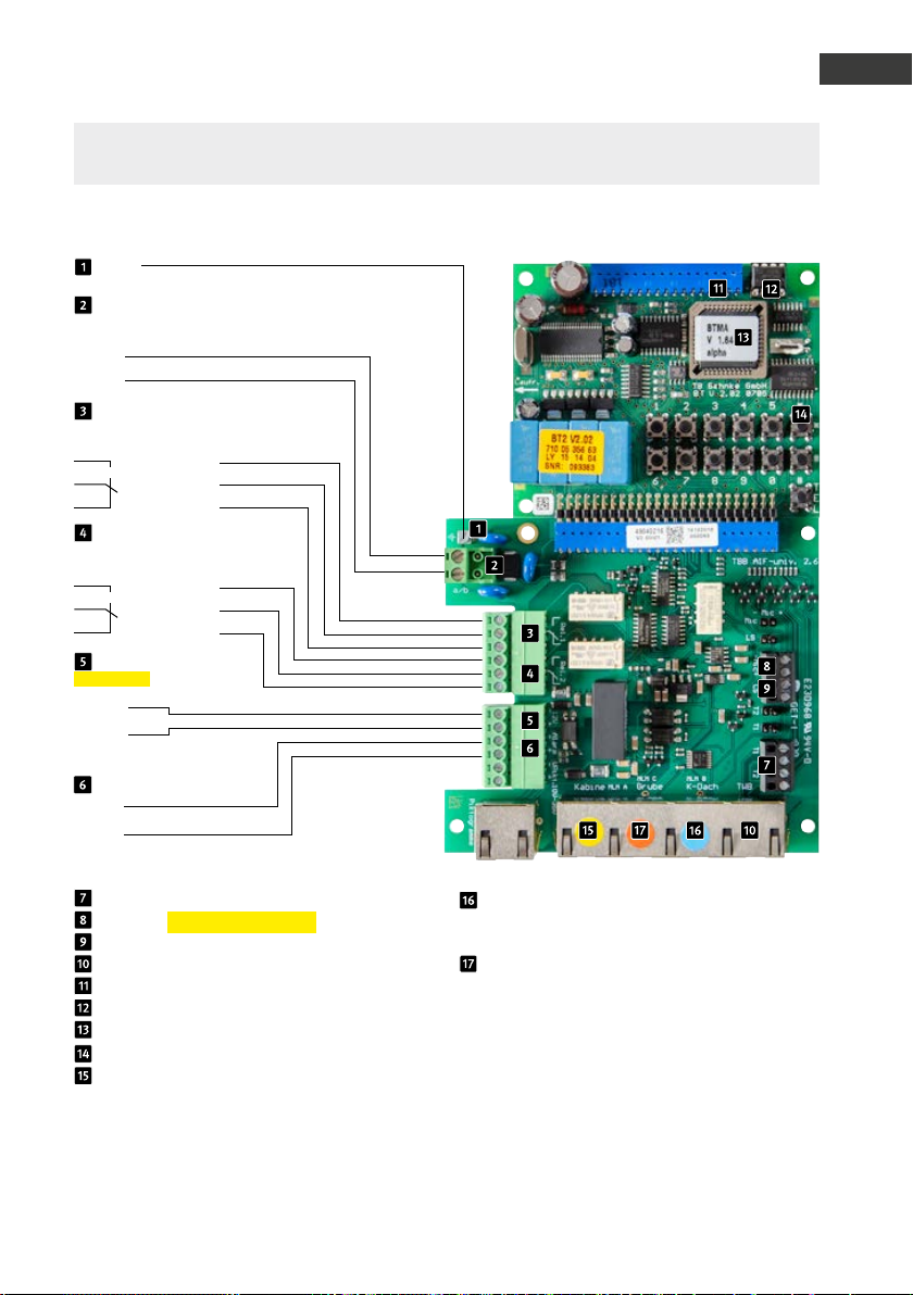
Anleitung Türstationen a / b Serie 20 / 30 / 40 / 50 / 20-0028A/-0028B
Anschluss
Hinweis: Bitte vergleichen Sie ihre Anschlussplatinen des gelieferten Gerätes/Rep-Kit mit den
Anschlussplatinen auf dem Foto. Weitere Konfigurationsschritte finden Sie ab Seite 26.
Universalelektronik 20-0006/-0018/-0026 (ab 1. Quartal 2019)
Erde
Telefonleitung
Analoger Hauptsanschluss oder Nebenstelle
einer Telefonanlage
a-Ader
b-Ader
Relais 1
Relaisschaltleistung: max. 60 VA 24 W
0,5 A 120 V~ oder 1A 24V=
Arbeitskontakt
Steuerkontakt
Ruhekontakt
Relais 2
Relaisschaltleistung: max. 60 VA
24 W 0,5 A 120 V~ oder 1A 24V=
Arbeitskontakt
Steuerkontakt
Ruhekontakt
Zusatzversorgung
potentialfreie Spannung
z. B. von Behnke Steckernetzteil
–
12 V - 15 V=
+
D
Alarmeingang
–
6 - 24 V =
+
Bei diesem Ger ät ungenutzt
Taster 1 + 2 (potentialfreier Schließer)
Mikrofon (Polarität beachten)
Lautsprecher
Tastwahlblock
Anschluss für Zusatzplatinen
EEprom
{
MLM B (Zusatz-MLM) – Mikrofon Lautsprecher-Modul (Konfigurations schritt 23 / Taste 3)
MLM C (Zusatz-MLM) – Mikrofon Lautsprecher-Modul (Konfigurations schritt 24 / Taste 4)
Masterprozessor
Interne Konfigurationstastatur
MLM A (Haupt-MLM) – Mikrofon Lautsprecher-Modul (Konfigurations schritt 22 / Taste 2)
Hinweis: Beim Anschluss mehrerer MLMs verkürzt sich die maximale Entfernung zwischen MLM und Basiselektronik:
1 MLM = 25 m / 2 MLMs = je 12,5 m / 3 MLMs = je 8,5 m
Passendes Installationsmaterial zur Adaption von Lautsprecher, Mikrofon und Tasten an der Tür: Abzweigbox 20-9208
alternativ Patchkabel 20-9309
Konfiguration der Rufnummern
Gelb: Konfigurationsschritt 22
Blau: Konfigurationsschritt 23
Rot: Konfigurationsschritt 24
17www.behnke-online.de
Page 18
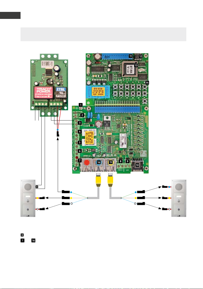
Anleitung Türstationen a / b Serie 20 / 30 / 40 / 50 / 20-0028A/-0028B
D
Anschluss
Hinweis: Bitte vergleichen Sie ihre Anschlussplatinen des gelieferten Gerätes/Rep-Kit mit den
Anschlussplatinen auf dem Foto. Weitere Konfigurationsschritte finden Sie ab Seite 26.
Universalelektronik 20-0048 (bis 4.Quartal 2018)
Zusatz-
versorgung
*
T
Lautsprecher zu LS+ / - auf ZV
bis siehe Universalelektronik
20-0006 / 20-0018 / 20-0026 auf S. 16
T
Konfiguration der Rufnummern
Gelb: Konfigurationsschritt 22
Blau: Konfigurationsschritt 23
Hinweis: Bitte beachten Sie die Angaben zu
Leitungslängen auf Seite 4!
*Passendes Installationsmaterial zur Adaption von Lautsprecher, Mikrofon und Tasten an der Tür: Abzweigbox 20-9208 alternativ
Patchkabel 20-9309
18 www.behnke-online.de
TT
PKWLKW
Page 19

Anleitung Türstationen a / b Serie 20 / 30 / 40 / 50 / 20-0028A/-0028B
Anschluss
Hinweis: Bitte vergleichen Sie ihre Anschlussplatinen des gelieferten Gerätes/Rep-Kit mit den
Anschlussplatinen auf dem Foto. Weitere Konfigurationsschritte finden Sie ab Seite 26.
Universalelektronik 20-0048 (ab 1. Quartal 2019)
D
Zusatz-
versorgung*
Achtung: Polarität beachten
zu
*
T
Lautsprecher zu LS+ / - auf ZV
bis siehe Universalelektronik
20-0006 / 20-0018 / 20-0026 auf S. 17
Konfiguration der Rufnummern
Gelb: Konfigurationsschritt 22
Blau: Konfigurationsschritt 23
Hinweis: Bitte beachten Sie die Angaben zu
Leitungslängen auf Seite 4!
*Passendes Installationsmaterial zur Adaption von Lautsprecher, Mikrofon und Tasten an der Tür: Abzweigbox 20-9208 alternativ
Patchkabel 20-9309
**potentialfreie Spannung z. B. von Behnke Steckernetzteil
TTT
LKWPKW
19www.behnke-online.de
Page 20
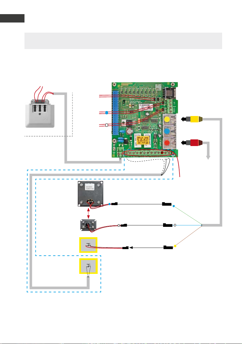
Anleitung Türstationen a / b Serie 20 / 30 / 40 / 50 / 20-0028A/-0028B
D
Anschluss
Hinweis: Bitte vergleichen Sie ihre Anschlussplatinen des gelieferten Gerätes/Rep-Kit mit den
Anschlussplatinen auf dem Foto. Weitere Konfigurationsschritte finden Sie ab Seite 26.
Aufzugnotrufsprechstelle 20-0028A (bis Firmwarestand BT MA 1.63, ausgeliefert bis 3. Quartal 2018)
Analoger Hauptanschluss, analoge Nebenstelle einer Telefon-
anlage oder GSM-Gateway
Zur Taste
im Deckel
Zum Lautsprecher
im Deckel
Zum Mikrofon
im Deckel
Hängekabel
Einbaulautsprecher
20-9200 bis 20-9202
Abstand zw. Lautsprecher
!
und Mikrofon min. 15 cm
Einbaumikrofon
Alternativ
20-9204
Notruftaste
in der Kabine
Alternativ:
Notruftaste (T2) in
der Kabine direkt an
Aufzugnotruftelefon
über abgeschirmtes
Kabel
T1
Patchkabel gelb
20-9309
Patchkabel rot
20-9302
Schirm des Kabels
(Masse)
T2
Notruftaste
- Muss potentialfrei sein
- Normal konfigurierter Schließer (Auslieferungszustand)
- Optionaler Öffner (Konfigurationsschritt 970)
Alternative für potentialbehaftete Taste (ab 1.40):
- Gemäß Polarität Taste mit 6 – 24V am Alarmeingang anschließen
- Konfigurationsschritt 17 auf Wert 6 stellen (Auslösen wie T2)
Achtung: wird die Taste über den Schaltschrank angeschlossen, muss ein
Zwischenrelais im Notruftelefon eingesetzt werden.
Zur Außensprechstelle unter der
Kabine 20-9230
Belegung der
Klemmreihe siehe
auch Seite 16
T
Standard
20 www.behnke-online.de
Page 21

Anleitung Türstationen a / b Serie 20 / 30 / 40 / 50 / 20-0028A/-0028B
Anschluss
Kurz-Inbetriebnahme (Code, Wert, Bestätigung)
(Immer mit dem Betreiber abklären)
▸ Telefonleitung anschließen: während Initialisierung
ertönt ca. 10 Sekunden ein hoher Piepton.
▸ Konfigurationsmodus aktivieren: *, 0000
▸ Rufnummern eingeben
▸ erste Rufnummer: 21, Rufnummer, #
▸ zweite Rufnummer: 22, Rufnummer, #
▸ dritte Rufnummer: 23, Rufnummer, #
▸ bis zur neunten Rufnummer: 29, Rufnummer, #
▸ Sammelruf aktivieren,
Anzahl der zu wählenden Rufnummern: 20, 1 bis 9, #
(Achtung die Rufempfang-Endstelle
muss mit einem MFV-Ton den Anruf quittieren)
▸ Lautstärke-Regelung (optimale Einstellung = 7) 06,
1 97
, #
▸ Potentialbehaftete Taste an Alarmeingang: 17, 6, #
▸ Aktivierung der 900er Parameter: 900, 1, #
▸ Dämpfung der Sprachwaage (Rückkopplung beseitigen): 911, 15 bis 20, #
▸ Mikrofonpegel: 913, 1 bis 7, #
▸ Kabinentaste: Schließer (Standard) 970, 0, #
▸ Kabinentaste: Öffner 970, 1, #
(Achtung dieser Konfigurationsabschnitt muss aktiviert
werden bevor Sie den Öffner anschließen)
▸ Deaktivierung der 900er Parameter: 900, 0, #
▸ Konfigurationsmodus beenden: *
D
21www.behnke-online.de
Page 22

Anleitung Türstationen a / b Serie 20 / 30 / 40 / 50 / 20-0028A/-0028B
D
Anschluss
Hinweis: Bitte vergleichen Sie ihre Anschlussplatinen des gelieferten Gerätes/Rep-Kit mit den
Anschlussplatinen auf dem Foto. Weitere Konfigurationsschritte finden Sie ab Seite 26.
Aufzugnotrufsprechstelle 20-0028A (bis Firmwarestand BT MA 1.63, ausgeliefert bis 2. Quartal 2019 )
Relais 1
Relaisschaltleistung:
max. 60 VA 24 W 0,5 A 120 V~
oder 1A 24V=
Arbeitskontakt
Steuerkontakt
Ruhekontakt
Relais 2
Relaisschaltleistung:
max. 60 VA 24 W 0,5 A 120 V~
oder 1A 24V=
Arbeitskontakt
Steuerkontakt
Ruhekontakt
Zusatzversorgung
potentialfreie Spannung
–
12 V - 15 V=
+
Alarmeingang
–
6 - 24 V =
+
Bei diesem Ger ät ungenutzt
Einbaulautsprecher
20-9200 bis 20-9202
Abstand zw.
!
Lautsprecher und
Mikrofon min. 15 cm
Einbaumikrofon
20-9204
Notruaste in
der Kabine
Notruftaste
- Muss potentialfrei sein
- Normal konfigurierter Schließer (Auslieferungszustand)
- Optionaler Öffner (Konfigurationsschritt 970)
Alternative für potentialbehaftete Taste (ab 1.40):
- Gemäß Polarität Taste mit 6 – 24V am Alarmeingang anschließen
- Konfigurationsschritt 17 auf Wert 6 stellen (Auslösen wie T2)
Achtung: wird die Taste über den Schaltschrank ange schlossen, muss ein Zwischenrelais im Notruftelefon eingesetzt werden.
{
T
Hängekabel
Analoger Hauptanschluss,
analoge Nebenstelle einer Telefonanlage oder GSM-Gateway
*
Patchkabel rot
Patchkabel gelb
20-9309
20-9302
Zur Außensprechstelle
unter der Kabine 20-9230A
*Verbindungsstecker
zur Basiselektronik (für
den Betrieb notwendig)
Zum Mikrofon
im Deckel
Zum Lautsprecher
im Deckel
T1
Zur Taste
im Deckel
Alternative zu T2*
Schirm
22 www.beh nke-online.de
Page 23

Anleitung Türstationen a / b Serie 20 / 30 / 40 / 50 / 20-0028A/-0028B
Anschluss
Kurz-Inbetriebnahme (beispielhaft) (Code, Wert, Bestätigung)
(Immer mit dem Betreiber abklären)
▸ Telefonleitung anschließen:
während Initialisierung ertönt ca. 10 Sekunden ein hoher Piepton.
▸ Konfigurationsmodus aktivieren: *, 0000
▸ Rufnummern eingeben
▸ erste Rufnummer: 21, Rufnummer, #
▸ zweite Rufnummer: 22, Rufnummer, #
▸ dritte Rufnummer: 23, Rufnummer, #
▸ bis zur neunten Rufnummer: 29, Rufnummer, #
▸ Sammelruf aktivieren,
Anzahl der zu wählenden Rufnummern: 20, 1 bis 9, #
(Achtung die Rufempfang-Endstelle muss
mit einem MFV-Ton den Anruf quittieren)
▸ Lautstärke-Regelung (optimale Einstellung = 7) 06,
1 97
, #
▸ Potentialbehaftete Taste an Alarmeingang
(Taste führt Spannung zwischen 6 Volt= bis 24 Volt=): 17, 6, #
▸ Aktivierung der 900er Parameter: 900, 1, #
▸ Dämpfung der Sprachwaage (Rückkopplung beseitigen): 911, 15 bis 20, #
▸ Mikrofonpegel: 913, 1 bis 7, #
▸ Kabinentaste: Schließer (Wird von 20-0028A im Standard erwartet) 970, 0, #
▸ Kabinentaste: Öffner (Konfigurationsschritt ändern, Schließer Standard) 970, 1, #
(Achtung dieser Konfigurationsabschnitt muss aktiviert
werden bevor Sie den Öffner anschließen)
▸ Deaktivierung der 900er Parameter: 900, 0, #
▸ Konfigurationsmodus beenden: *
D
23www.behnke-online.de
Page 24
Anleitung Türstationen a / b Serie 20 / 30 / 40 / 50 / 20-0028A/-0028B
D
Anschluss
Hinweis: Bitte vergleichen Sie ihre Anschlussplatinen des gelieferten Gerätes/Rep-Kit mit den
Anschlussplatinen auf dem Foto. Weitere Konfigurationsschritte finden Sie ab Seite 26.
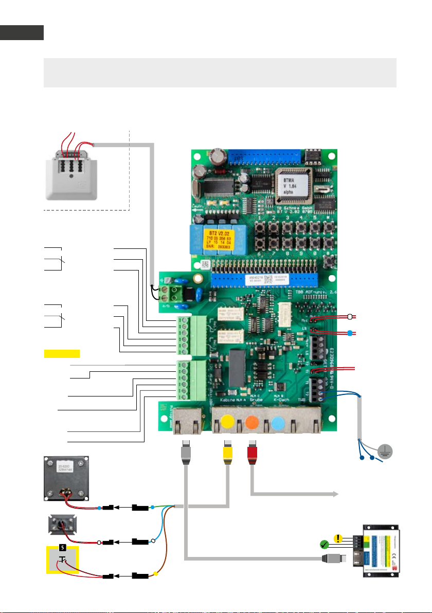
Aufzugnotrufsprechstelle 20-0028B (ab Firmwarestand BT MA 1.64, ab 2. Quartal 2019)
Analoger Hauptanschluss, analoge Nebenstelle einer Telefonanlage oder GSM-Gateway
Relais 1
Relaisschaltleistung: max. 60 VA 24 W
0,5 A 120 V~ oder 1A 24V=
Arbeitskontakt
Steuerkontakt
Ruhekontakt
Relais 2
Relaisschaltleistung: max. 60 VA
24 W 0,5 A 120 V~ oder 1A 24V=
Arbeitskontakt
Steuerkontakt
Ruhekontakt
Zusatzversorgung
potentialfreie Spannung
z. B. von Behnke Steckernetzteil
–
12 V - 15 V=
+
Alarmeingang
–
6 - 24 V =
+
Piktogrammansteuerung
–
10 - 35 V =
+
Abstand zw. Laut sprecher
und Mikrofon min. 15 cm
Einbaumikrofon
20-9204
Notruaste in
der Kabine
Hängekabel
Zum Mikrofon
im Deckel
Zum Lautsprecher
im Deckel
T1
Zur Taste
im Deckel
Alternative zu T2*
Patchkabel grau
20-9329
zu den bauseitigen Piktogrammen.
Achtung: techn. Daten der bauseitigen
Piktogramme beachten
T
Patchkabel Cat 5 max. 10 m
Patchkabel rot
20-9302
Patchkabel gelb
20-9309
Zur Außensprechstelle
unter der Kabine 20-9230
Alternativ: Frontblende
mit Piktogramm 22-9416
Schirm
24 www.behnke-online.de
Page 25

Anleitung Türstationen a / b Serie 20 / 30 / 40 / 50 / 20-0028A/-0028B
Anschluss
Kurz-Inbetriebnahme (beispielhaft) (Code, Wert, Bestätigung)
(Immer mit dem Betreiber abklären)
▸ Telefonleitung anschließen:
während Initialisierung ertönt ca. 10 Sekunden ein hoher Piepton.
▸Konfigurationsmodus aktivieren: *, 0000
(0000 = Sicherheitscode in Werksteinstellung)
▸Taste verzögern/gedrückt halten (in Sekunden): 04,
▸Lautstärke (Laustärkenstufe 1-9): 06,
1 93
1 97
, #
, #
▸Sammelruf aktivieren (max. 9): 20, 1-9, #
(Anzahl der zu wählenden Rufnummern)
▸ erste Rufnummer: 21, 1. Rufnummer, #
▸zweite Rufnummer: 22, 2. Rufnummer, #
▸dritte Rufnummer: 23, 3. Rufnummer, #
▸bis zur neunten Rufnummer: 29, 9. Rufnummer, #
(Achtung: Der Empfänger muss den Notruf mit
einem DTMF-Ton/ beliebige Taste quittieren)
▸Erweitere Konfiguration freigeben: 900, 1, #
▸Dämpfung Sprachwaage: 911, 15-20, #
▸Reduziert Anfälligkeit für Rückkopplung)
▸Verstärkung Sendesignal (Mikrofon 1-7): 913, 4, #
▸Verstärkung Empfangssignal (Lautsprecher 1-7): 914, 4, #
▸Routineruf alle 3 Tage auf Zielrufnummer x: 9921, 3*x, #
▸Routineruf endlos wiederholen auch bei Nicht-Quittierung: 9922, 0, #
▸Erweitere Konfiguration sperren: 900, 0, #
▸Konfigurationsmodus beenden: *
D
25www.behnke-online.de
Page 26
Anleitung Türstationen a / b Serie 20 / 30 / 40 / 50 / 20-0028A/-0028B
D
Konfiguration
.
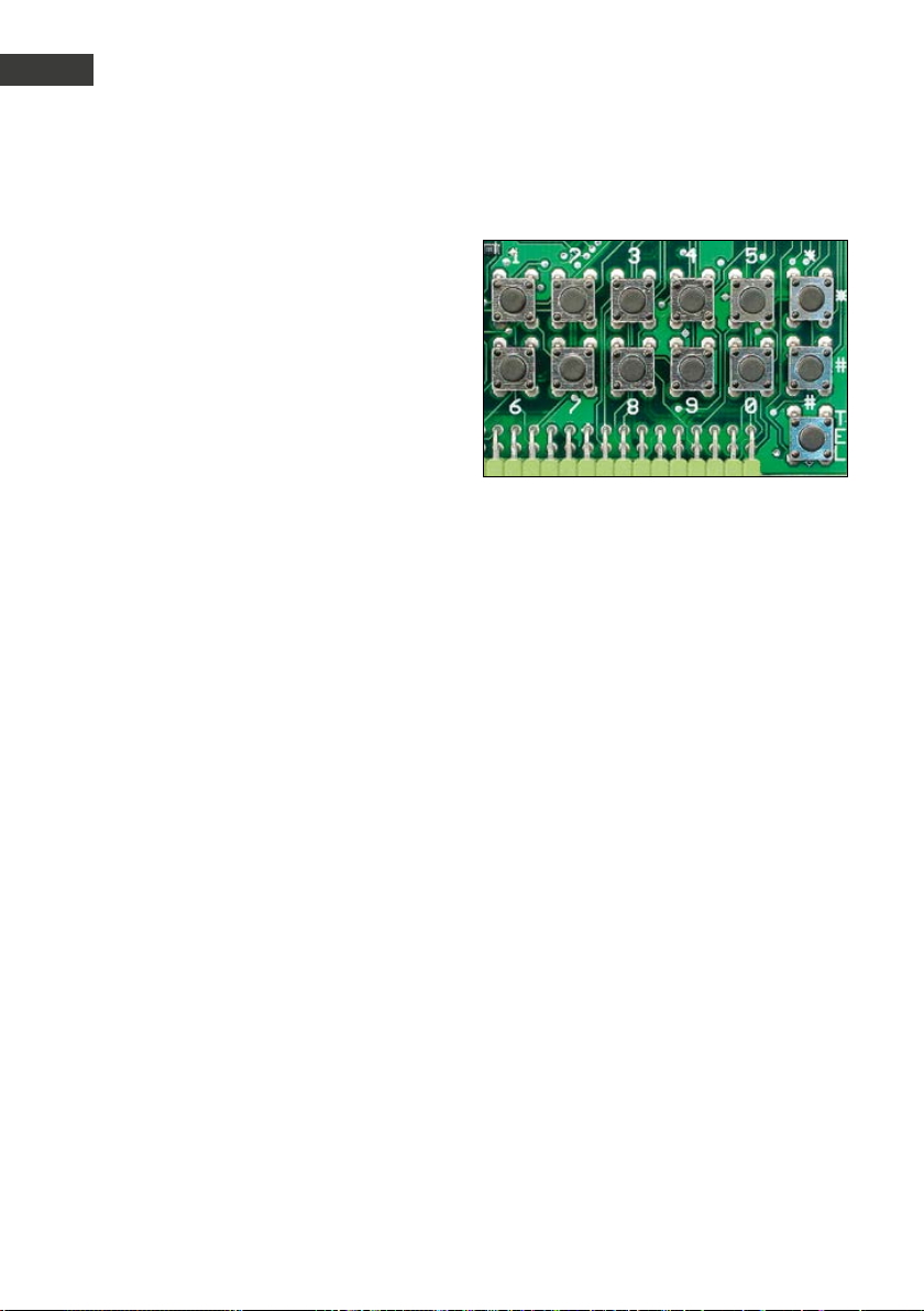
Die Konfiguration kann direkt an der Türstation über die interne Konfigurationstastatur
oder von Ferne über ein tonwahlfähiges Telefon erfolgen. Zusätzlich kann bei Türstationen
mit Tastwahlblock auch dieser zur Konfiguration verwendet werden. Um in den Konf igurationsmodus zu gelangen, muss ein 4-stelliger
Sicherheitscode eingegeben werden. Die
Konfiguration selbst erfolgt durch die Eingabe
von so genannten Konfigurationsschritten, die
jeweils eine bestimmte Funktion einstellen.
Konfigurationsmodus aktivieren:
lokal an der Türstation
Taste * kurz drücken (auf interner Konfigurati-
▸
onstastatur oder auf Tastwahlblock)
[Piep]
Sicherheitscode eingeben (Vorgabe: 0 0 0 0)
▸
[Piep] [Piep]
von Ferne mit tonwahlfähigem Telefon
Türstation anrufen
▸
Türstation hebt ab und meldet sich mit einem
▸
Piepton
Taste * nach dem Piepton zweimal drücken.
▸
[Piep]
Sicherheitscode eingeben (Vorgabe: 0 0 0 0)
▸
[Piep] [Piep]
Konfigurationsschritte eingeben:
Konfigurationscode eingeben (siehe Tabelle
▸
der Konfigurationsschritte)
[Piep] [Piep]
Parameter eingeben und mit Taste #
▸
abschließen
[Piep] [Piep] [Piep]
Konfigurationsmodus beenden:
Taste * kurz drücken oder 30 Sekunden keine
▸
Eingabe
Konfigurationsbeispiele direkt an der
Sprechstelle:
*0000 Einstieg Konfiguration
10 Code zum Türöffnen #
21 Rufnummer soll bei Tastendruck die Taste 1
wählen #
:
28 Rufnummer soll bei Tastendruck die Taste 8
wählen #
* Konfiguration beenden
26 www.behnke-online.de
Page 27

Anleitung Türstationen a / b Serie 20 / 30 / 40 / 50 / 20-0028A/-0028B
Konfiguration
Code Parameter Bestätigung
Reset und Auslieferungszustand herstellen:
00
* * * * #
Sicherheitscode ändern: Vorgabe: 0 0 0 0
01
neuer Code [Piep] neuer Code #
D
Konfiguration: Vorgabe: 0
02
0 = möglich lokal am Gerät und per Ferne
1 = nur möglich per Ferne
Anrufannahme: Vorgabe: 1
03
0 = manuell auf Tastendruck
1 = automatisch
2 = automatisch mit Codeabfrage (Anrufschutz)
3 = automatisch mit manueller Bestätigung (ab V1.60)
Einschaltverzögerung für Direktruftasten: Vorgabe: 0
04
0 = keine
1 = 1 Sekunde
:
9 = 9 Sekunden
Verbindungsdauer: Vorgabe: 3
05
0 = unbegrenzt (d.h. begrenzt auf ca. 8 Stunden)
1 = auf 1 Minute begrenzt
:
9 = auf 9 Minuten begrenzt
06 Lautstärke: Vorgabe: 5
0 = leise
:
9 = laut
#
#
#
#
#
#
#
#
:
#
#
#
:
#
#
:
#
27www.behnke-online.de
Page 28

Anleitung Türstationen a / b Serie 20 / 30 / 40 / 50 / 20-0028A/-0028B
D
Konfiguration
Code Parameter Bestätigung
Zusatzverstärker: Vorgabe: 0
07
0 = inaktiv
1 = leise
:
9 = laut
Hinweis: Hier ist es sinnvoll Werte im Bereich 1 bis 4 einzustellen.
Betriebsart Relais 1: Vorgabe: 6
08
0 = inaktiv
1 = aktivierbar über Telefon
2 = aktivierbar über Tastwahlblock
3 = aktivierbar über Telefon und Tastwahlblock
4 = aktivierbar über Telefon & Auflegen nach Aktivierung
5 = aktivierbar über Tastwahlblock & Auflegen nach Aktivierung
6 = aktivierbar über Telefon und Tastwahlblock & Auflegen nach Aktivierung
7 = aktiviert während abgehender Verbindungen
8 = aktiviert während eingehender Verbindungen
9 = aktiviert während ab- und eingehender Verbindungen
10 = aktiviert am Anfang von abgehenden Verbindungen
11 = aktiviert am Anfang von eingehenden Verbindungen
12 = aktiviert am Anfang von ab- und eingehenden Verbindungen
13 = aktiviert während Klingeln
14 = aktiviert bei Störung (Telefonleitung ausgefallen)
15 = aktivierbar über Notrufleitstand
16 = aktiviert während einem Direktruf über Taste 1 (ab V1.20)
17 = aktiviert am Anfang eines Direktrufes über Taste 1 (ab V1.20)
18 = manuelle Aktivierung (ab V1.30)
19 = automatische Aktivierung gemäß Zeitplan
(siehe Konfigurationsschritt 43) (ab V1.30)
20 = aktiviert nach Abgabe eines Notrufs (gemäß EN 81-70) (ab V1.40)
21 = aktiviert beim Sprechen im Wechselsprechbetrieb (ab V1.42)
22 = aktiviert beim Hören im Wechselsprechbetrieb (ab V1.42)
#
#
:
#
#
#
#
#
#
#
#
#
#
#
#
#
#
#
#
#
#
#
#
#
#
#
#
28 www.behnke-online.de
Page 29

Anleitung Türstationen a / b Serie 20 / 30 / 40 / 50 / 20-0028A/-0028B
Konfiguration
Code Parameter Bestätigung
Aktivierungsdauer Relais 1: Vorgabe: 5
09
1 = 1 Sekunde
2 = 2 Sekunden
:
30 = 30 Sekunden (bis V1.60)
#
#
:
#
:
90 = 90 Sekunden (ab V1.61)
Aktivierungscode Relais 1: Vorgabe: 0
10
1. Aktivierungscode
11
2. Aktivierungscode
#
#
Die Aktivierungscodes bestehen nur aus Ziffern u. sind maximal vierstellig.
Betriebsart Relais 2: Vorgabe: 9
12
0 = inaktiv
1 = aktivierbar über Telefon
2 = aktivierbar ü. Tastwahlblock
3 = aktivierbar ü. Telefon und Tastwahlblock
4 = aktivierbar ü. Telefon & Auflegen nach Aktivierung
5 = aktivierbar ü. Tastwahlblock & Auflegen nach Aktivierung
6 = aktivierbar ü. Telefon und Tastwahlblock & Auflegen nach Aktivierung
7 = aktiviert während abgehender Verbindungen
8 = aktiviert während eingehender Verbindungen
9 = aktiviert während ab- und eingehender Verbindungen
10 = aktiviert am Anfang von abgehenden Verbindungen
11 = aktiviert am Anfang von eingehenden Verbindungen
12 = aktiviert am Anfang von ab- und eingehenden Verbindungen
13 = aktiviert während Klingeln
14 = aktiviert bei Störung (Telefonleitung ausgefallen)
15 = aktivierbar über Notrufleitstand
16 = aktiviert während einem Direktruf über Taste 2 (ab V1.20)
17 = aktiviert am Anfang eines Direktrufes über Taste 2 (ab V1.20)
18 = manuelle Aktivierung (ab V1.30)
19 = Aktivierung gemäß Zeitplan
#
#
#
#
#
#
#
#
#
#
#
#
#
#
#
#
#
#
#
#
(bzw. manuell, siehe Konfigurationsschritt 44) (ab V1.30)
20 = aktiviert nach Annahme eines Notrufes (gemäß EN 81-70) (ab V1.40)
#
D
29www.behnke-online.de
Page 30
Anleitung Türstationen a / b Serie 20 / 30 / 40 / 50 / 20-0028A/-0028B
D
Konfiguration
Code Parameter Bestätigung
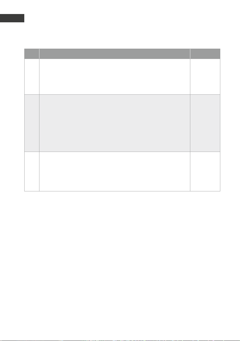
21 = aktiviert beim Sprechen im Wechselsprechbetrieb (ab V1.42)
22 = aktiviert beim Hören im Wechselsprechbetrieb (ab V1.42)
23 = steuert Zusatzrelais-Adapter (ab V1.51)
24 = IP-Video-Routing (ab V1.61)
Aktivierungsdauer Relais 2: Vorgabe: 5
13
1 = 1 Sekunde
2 = 2 Sekunden
:
30 = 30 Sekunden (bis V1.60)
:
90 = 90 Sekunden (ab V1.61)
Aktivierungscodes Relais 2: Vorgabe: s. Konfigurationsschritt 12
14
1. Aktivierungscode
15
2. Aktivierungscode
Die Aktivierungscodes bestehen nur aus Ziffern u. sind maximal vierstellig.
#
#
#
#
#
#
:
#
30 www.behnke-online.de
Page 31

Anleitung Türstationen a / b Serie 20 / 30 / 40 / 50 / 20-0028A/-0028B
Konfiguration
Code Parameter Bestätigung
Sammelruf /Abhörschutz / unverlierbarer Ruf / EN 81-28/70-Betrieb:
20
Vorgabe: 0
0 = inaktiv (Sammelruf, Abhörschutz und unverlierbarer Ruf inaktiv)
1 = Rufnummer 1 anwählen (Abhörschutz & unverlierbarer Ruf)
2 = Rufnummern 1 bis 2 anwählen (Abhörschutz & unverlierb. Ruf)
:
8 = Rufnummern 1 bis 8 anwählen (Abhörschutz & unverlierb. Ruf)
9 = Rufnummern 1 bis 9 anwählen (Abhörschutz & unverlierb. Ruf)
#
#
#
:
#
#
Bei aktiviertem Sammelruf werden bei Betätigung einer beliebigen Direktwahltaste (außer Taste i) die entsprechenden Rufnummern (1 bis x) nacheinander angewählt, bis jemand erreicht wird, der den Empfang ordnungsgemäß mit einem beliebigen DTMF-Ton quittiert, oder alle Rufnummern
angewählt wurden. Bei x=9 wird auch die Taste i in den Sammelruf einbezogen, sonst wird bei Betätigung der Taste i die Rufnummer 9 angewählt.
Ab V1.61 wird bei einem Sammelruf, der nur aus einer Rufnummer besteht
(KS 20 auf 1) der Anruf nach Ablauf der Bestätigungsdauer nicht beendet,
sondern die Verbindung bleibt auch ohne Bestätigung bestehen.
D
Bei aktiviertem Sammelruf sind auch die Funktionen Abhörschutz und
unverlierbarer Ruf aktiviert. Bei aktiviertem Abhörschutz sendet das Gerät
alle 30 Sekunden einen Doppelpiep in die Verbindung. Bei aktivierter
Funktion unverlierbarer Ruf ist das Beenden der Verbindung durch Tastenbetätigung nicht erlaubt.
EN 81-28/70-Betrieb: Durch zusätzliche Eingabe eines * nach der Sammelrufziffer vor dem Bestätigen mit Raute (z.B. 20 4 * # für Sammelruf auf
4) kann auf EN81-28/70-Betrieb umgeschaltet werden. Hierzu werden die
Relais automatisch auf Betriebsart 20 umgestellt (siehe KS 08 und KS 12).
Außerdem wird dann bei aktiviertem Sammelruf die Ausführung automatischer täglicher Testanrufe aktiviert (siehe KS 9921).
31www.behnke-online.de
Page 32
Anleitung Türstationen a / b Serie 20 / 30 / 40 / 50 / 20-0028A/-0028B
D
Konfiguration
Code Parameter Bestätigung
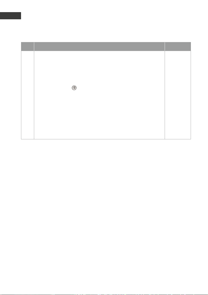
21
Rufnummer für Taste 1
22
Rufnummer für Taste 2
23
Rufnummer für Taste 3 (nur Serie 20)
:
:
28
Rufnummer für Taste 8 (nur Serie 20)
29
Rufnummer für Taste des Tastwahlblocks (nur Serie 20)
#
#
#
:
#
#
Die Rufnummern bestehen nur aus Ziffern und sind maximal 20-stellig. Bei
der Eingabe der Rufnummern sind folgende Sondersymbole (siehe Kapitel
Programmierung) zulässig:
*0 = * wählen
*1 = # wählen
*2 = 2 Sekunden Pause
*3 = Warten auf Wählton
32 www.behnke-online.de
Page 33

Anleitung Türstationen a / b Serie 20 / 30 / 40 / 50 / 20-0028A/-0028B
Konfiguration
Code Parameter Bestätigung
ab Version 1.30:
*4 x Bedingung
x=0 immer
x=1 wenn Zeitplan 1 erfüllt (nur mit Uhr-Modul sinnvoll)
x=2 wenn Zeitplan 2 erfüllt (nur mit Uhr-Modul sinnvoll)
x=3 wenn Zeitplan 1 nicht erfüllt (nur mit Uhr-Modul sinnvoll)
x=4 wenn Zeitplan 2 nicht erfüllt (nur mit Uhr-Modul sinnvoll)
x=5 wenn technischer Alarm (nur bei Konfigurationsschritt 17>0
sinnvoll)
x=6 wenn kein technischer Alarm (nur bei Konfigurations schritt 17>0 sinnvoll)
x=7 wenn Alarmeingang aktiv (nur sinnvoll bei Konfigurations schritt 17>0)
x=8 wenn Alarmeingang nicht aktiv (nur bei Konfigurations schritt 17>0 sinnvoll)
x=9 sonst (nur sinnvoll, wenn vorher andere *4x-Bedingung)
*5 x Sprachansage Nr. x abspielen (nur mit Sprachansage-Modul
sinnvoll)
*5 0 Signalton-Folge abspielen
*6 x Text Nr. x im Display anzeigen (nur mit Display-Modul sinnvoll)
*7 x Relais aktivieren (1=Relais 1, 2=Relais 2, 3=Relais 1&2)
*8 x y Warten auf Abheben (x=Sprachansage, die während dem
Warten auf Abheben und y=Sprachansage, die nach dem
Abheben abgespielt werden soll) (nur mit Erweiterungsmodul
sinnvoll)
*9 x Zeiger auf Rufnummer (x=1..9)
*9 0 x Zeiger auf Kurzwahl (x=00..99)
** x individueller Sammelruf (x=1..9=nächste Rufnummer)
D
33www.behnke-online.de
Page 34
Anleitung Türstationen a / b Serie 20 / 30 / 40 / 50 / 20-0028A/-0028B
D
Konfiguration
Code Parameter Bestätigung
** 0 Hotline-Funktion
*# Flash-Funktion
** ** Anwahl beenden
** *0 Stummschaltung aus
** *1 Stummschaltung ein
ab Version 1.34:
*4** 1 wenn Relais 1 eingeschaltet ist
*4** 2 wenn Relais 2 eingeschaltet ist
*4* x y Variablen-Wert prüfen (Bedingung) (x=0..9, y=0..9) x=y?
Bedingung ist erfüllt, wenn die Variable x den Wert y hat
*5* x y Variablen-Wert setzen (x=0..9, y=0..9) x:=y
setzt die Variable x auf den Wert y
*5** x Variable inkrementieren (x=0..9) x++
inkrementiert die Variable x (für x=9, gilt x++=0)
*6* 0 Timer deaktivieren
*6* x mm Direktruftaste x (x=1..9) nach mm (mm=00..99) Minuten
auslösen
*74 Relais 1 ausschalten (nur bei Betriebsart 18)
*75 Relais 1 einschalten (nur bei Betriebsart 18)
*76 Relais 2 ausschalten (nur bei Betriebsart 18)
*77 Relais 2 einschalten (nur bei Betriebsart 18)
Kurzwahlnummer: Vorgabe: s. Text
300
Kurzwahl Kurzwahlnummer 00
301
Kurzwahl Kurzwahlnummer 01
:
399
Kurzwahl Kurzwahlnummer 99
#
#
:
#
Erweiterte Konfiguration: Vorgabe: 0
900
0 = nicht erlaubt
1 = erlaubt
#
#
Nur wenn er weiterte Konfiguration erlaubt ist, können die folgenden
Konfigurationsschritte eingegeben werden.
34 www.behnke-online.de
Page 35

Anleitung Türstationen a / b Serie 20 / 30 / 40 / 50 / 20-0028A/-0028B
Konfiguration
Code Parameter Bestätigung
Verstärkung Mikrofonsignal (ohne ZV): Vor gabe: 0/0
912
0 = 0 dB
1 = 6 dB
2 = 12 dB
3 = 18 dB
#
#
#
#
Verstärkung Mikrofonsignal (mit ZV): Vorgabe: 0/0
922
0 = 0 dB
1 = 6 dB
2 = 12 dB
3 = 18 dB
#
#
#
#
Abweichende Kongurationsschritte bei Universalgeräten
(20-0005/-0006/-0018/-0026/-0028A/-0028B/-0048)
21
Rufnummer für Taste 1
22
Rufnummer für Taste 2 bzw. MLM A (gelbe Buchse)
23
Rufnummer für Taste 3 bzw. MLM B (blaue Buchse)
24
Rufnummer für Taste 4 bzw. MLM C (rote Buchse)
25
Rufnummer für Taste 5
:
:
28
Rufnummer für Taste 8
29
Rufnummer für Taste des Tastwahlblocks
#
#
#
#
#
:
#
#
D
Weitere Konfigurationsschritte, wie Relaissteuerung, Akustikeinstellungen, Erweiterungselektronik Sprachansage / Echtzeituhr etc., finden Sie im ausführlichen technischen Handbuch
(www.behnke-online.de/handbuch-analog).
35www.behnke-onlin e.de
Page 36

Anleitung Türstationen a / b Serie 20 / 30 / 40 / 50 / 20-0028A/-0028B
D
Bedienung
.
Funktionen an der Türstation (= außen)
Anrufen per Ruaste
Eine der Ruftasten drücken (oder Taste
▸
des Tastwahlblocks)
Die für die Taste einprogrammierte Rufnummer
▸
wird gewählt.
Bei Rufannahme wird eine Sprachverbindung
▸
aufgebaut (Standardeinstellung = Voll-duplex);
Verbindung wird automatisch wieder beendet
(auf erkannten Besetzton hin) oder nochmaliges Drücken der Ruftaste.
Anrufen per Tastwahlblock mit Wahltaste
drücken – Freizeichen ist zu hören.
▸
Rufnummer am Tastwahlblock wählen, z.B.
▸
interne Nebenstellennummer 127
Bei Rufannahme wird eine Sprachverbindung
▸
aufgebaut (Standardeinstellung = Vollduplex); Verbindung wird automatisch wie-der
beendet (auf erkannten Besetzton hin).
Anrufen per Tastwahlblock mit Kurzwahltaste
drücken – Freizeichen ist zu hören.
▸
2-stellige Kurzwahlnummer (00 bis 99) am
▸
Tastwahlblock wählen, z.B. 31
Bei Rufannahme wird eine Sprachverbindung
▸
aufgebaut (Standardeinstellung = Vollduplex); Verbindung wird automatisch wie-der
beendet (auf erkannten Besetzton hin).
Türönen per Tastwahlblock mit Codeschloss-
taste
drücken – Freizeichen ist zu hören.
▸
Codeziffer eingeben (Standard = 0)
▸
drücken – der Türöffner wird ausgelöst (über
▸
den Relaiskontakt der Türstation).
Funktionen am Telefon (= innen):
Rufannahme – Sprachverbindung bei Anruf von
der Tür
Je nach verwendeter Telefonanlage und Telefon-
▸
apparat kann in Ihrem Display die Nummer der
Türstation oder eine Textinformation wie z.B.
„Türstation“ angezeigt werden (Leistungsmerkmal der TK-Anlage).
Anruf von der Tür wie einen normalen Telefon-
▸
anruf entgegennehmen.
Sprachverbindung durch Auflegen beenden.
▸
Türönen von innen
Codeziffer eingeben (Standard 0)
▸
drücken – der Türöffner wird ausgelöst.
▸
Systemtelefone von Siemens, Alcatel, Tenovis
oder anderen Herstellern auf „MFV-Nachwahl“
einstellen = Tonwahl (erforderlich für Türöffnerfunktion u.a.)!
Weitere Möglichkeiten der Bedienung finden Sie
im ausführlichen technischen Handbuch (www.
behnke-online.de/handbuch-analog)
Umschalten zwischen den einzelnen MikrofonLautsprechermodulen (MLM A bis C und integriertes MLM):
MLM B aktivieren
(MLM auf der Kabine; blaue Buchse)
MLM A aktivieren
(MLM in der Kabine; gelbe Buchse)
MLM C aktivieren
(MLM unter der Kabine; rote Buchse)
zwischem MLM A (in der Kabine) und
integriertem Mikrofon in der Türsprechstelle
umschalten
36 www.behnke-online.de
Page 37
Anleitung Türstationen a / b Serie 20 / 30 / 40 / 50 / 20-0028A/-0028B
Erweiterte Bedienung
.
6.1. Steuerungsmöglichkeiten während Sprachverbindungen
Während einer Sprachverbindung bietet die Türstation folgende Steuerungsmöglichkeiten, die über
ein tonwahlfähiges Telefon aktiviert werden können:
Eingabe Funktion
D
Aktivierungscode #
## x Lautstärke auf x einstellen (x=0 bis 9)
##* Sicherheitscode 0
##* Sicherheitscode 1
##* Sicherheitscode 2
### Sprachansage abspielen (ab V1.30)
*# Auflegen (Funktion ab V1.34 über Konfigurationsschritt 9918 einstellbar)
** Konfigurationsmodus aktivieren (anschließend Sicherheitscode eingeben)
Relais aktivieren
Damit ein Relais über einen Aktivierungscode aktiviert werden kann, müssen die
Betriebsart des Relais, die Aktivierungsdauer und natürlich der Aktivierungscode
korrekt eingestellt sein.
Die Lautstärke-Einstellung ist nur für die aktuelle Verbindung gültig. Soll die
Lautstärke permanent eingestellt werden, so ist dies nur über die Konfigurationsschritte 06, 07 bzw. 988 möglich.
Autom. Akustik-Einstellung (ohne Zusatzverstärker) (ab V1.51)
siehe nächster Abschnitt
Autom. Akustik-Einstellung (mit Zusatzverstärker) (ab V1.51)
siehe nächster Abschnitt
Autom. Akustik-Einstellung (Modus beibehalten) (ab V1.51)
siehe nächster Abschnitt
Es wird die für diese Funktion eingestellte Sprachansage abgespielt.
*0 Umschalten zwischen Betrieb mit und ohne Zusatzverstärker
1x ok-Piep ▸ Betrieb ohne Zusatzverstärker
2x ok-Piep ▸ Betrieb mit Zusatzverstärker
Fehler-Piep ▸ Betrieb mit Zusatzverstärker nicht möglich oder nicht erlaubt
37www.behnke-online.de
Page 38
Anleitung Türstationen a / b Serie 20 / 30 / 40 / 50 / 20-0028A/-0028B
D
Erweiterte Bedienung
Eingabe Funktion
Das Umschalten zwischen Betrieb mit und ohne Zusatzverstärker ist nur möglich,
wenn der Zusatzverstärker über Konfigurationsschritt 07 aktiviert ist, und eine
Zusatzversorgung von 12 V angeschlossen ist.
*8 Auflegen (nur möglich ab V1.34 und wenn die *#-Funktion über Konfigurations-
schritt 9918 auf eine andere Funktion wie Auflegen umgestellt wurde)
*8 Sicherheitscode #
Notrufzustand zurücksetzen (nur möglich ab V1.40)
Bei aktiviertem Sammelruf geht das Gerät bei einem ausgelösten Sprachnotruf
in den Notrufzustand (Deaktivierung der Missbrauchsunterdrückung). Durch Eingabe von *8 gefolgt von Sicherheitscode und # kann der Notrufzustand zurückgesetzt werden. Wenn Konfigurationsschritt 9919 auf 0 konfiguriert ist, kann die
Eingabe des Sicherheitscodes entfallen und der Notrufzustand kann sogar über
*8# zurückgesetzt werden. Bei korrekter Eingabe wird das Zurücksetzen des
Notrufzustandes mit 2x ok-Piep bestätigt, ansonsten ertönt ein Fehler-Piep.
Achtung: Das Zurücksetzen des Notrufzustand über die *8-Funktion ist nur
möglich, wenn die *#-Funktion über Konfigurationsschritt 9918 auf Auflegen
eingestellt ist.
*9 Zustand des Alarmeingangs abfragen
1x ok-Piep ▸ Alarmeingang inaktiv
2x ok-Piep ▸ Alarmeingang aktiv
Der Zustand des Alarmeinganges kann bei allen Betriebsarten des Alarmeinganges (Konfigurationsschritt 17) außer bei Betriebsart 0 (inaktiv) abgefragt werden.
Die folgende Befehle sind nur bei Universalgeräten möglich:
*1 MLM B aktivieren (Dach) falls das MLM B nicht angeschlossen
=MLM für auf die Kabine ist, wird das integrierte MLM aktiviert
*2 oder *4 MLM A aktivieren (Kabine) falls das MLM A nicht angeschlossen
=MLM für in die Kabine ist, wird das integrierte MLM aktiviert
*3 oder *7 MLM C aktivieren (Grube) falls das MLM C nicht angeschlossen
=MLM für unter die Kabine ist, wird das integrierte MLM aktiviert
38 www.behnke-online.de
Page 39

Anleitung Türstationen a / b Serie 20 / 30 / 40 / 50 / 20-0028A/-0028B
Erweiterte Bedienung
6.2. Automatische Akustik-Einstellung mit ##*-Funktion (ab V1.51)
D
Mit der ##*-Funktion können die Werte für die
akustischen Einstellungen (Lautstärke, Mikrofonempfindlichkeit, Sendesignalverstärkung,
Empfangssignalverstärkung, Dämpfung der
Sprachwaage) automatisch bestimmt werden.
Dazu wie folgt vorgehen: Türsprechstelle mit
einem MFV-wahlfähigen Telefon anrufen. Die
Türsprechstelle nimmt den Ruf an, mind. 5 Sek.
warten und danach zügig die Tastenfolge ##*
Sicherheitscode 0/1/2 eingeben.
Folgende Modi für die Akustikeinstellung sind
möglich:
0 automatische Akustik-Einstellung für
Betrieb ohne Zusatzverstärker
1 automatische Akustik-Einstellung für
Betrieb mit Zusatzverstärker
2 automatische Akustik-Einstellung
(Modus beibehalten: Betrieb mit Zusatz-verstärker, falls dieser bereits aktiviert, sonst
Betrieb ohne Zusatzverstärker)
Beim Anruf der ##*-Funktion ist auf eine
flüssige Eingabe (=keine längeren Pausen
zwischen den einzelnen Zeichen) zu achten.
Bei Eingabe eines falschen Sicherheitscodes
legt die Türstation auf. Sollte die automatische
Akustik-Einstellung nicht möglich sein, weil
beispielsweise der Zusatzverstärker verwendet
werden soll, aber keine 12 VZusatzversorgung angeschlossen ist, dann gibt
die Türstation nach Eingabe des Modus einen
Fehlerpiepton aus.
Achtung: Während die automatische AkustikEinstellung läuft, sollten an der Türstation
möglichst keine Hintergrundgeräusche vorhanden sein und das verwendete Telefon sollte
sich nicht in direkter Umgebung der Türstation
befinden und auch nicht im Freisprechmodus
verwendet werden. Halten Sie während der
automatischen Einstellung den Telefonhörer
nicht direkt ans Ohr, denn gegen Ende der automatischen Einstellung ist im Allgemeinen ein
lauter Pfeifton zu hören (Rückkopplung). Die ist
normal und zur Bestimmung der Einstellungen
notwendig. Die automatische Einstellung dauert
etwa 20 Sekunden. Sobald die automatische
Einstellung beendet ist, gibt die Türstation
einen Doppelpiep aus.
39www.be h nke-online.de
Page 40
Anleitung Türstationen a / b Serie 20 / 30 / 40 / 50 / 20-0028A/-0028B
D
Erweiterte Bedienung
6.3. Rufannahme bei aktivierter Wahlwiederholung / Sammelruf (Konfigurationsschritt 20 aktiv)
Nach dem Abheben des Hörers die Taste
drücken, um den Anruf entgegenzunehmen.
Ansonsten wird die Verbindung automatisch
unterbrochen, da die Wahlwiederholung / der
Sammelruf weiterläuft und die nächste Nummer
gewählt wird. Telefon mit Tonwahl erforderlich
Eingabe Funktion
*1 MLM B aktivieren
(Falls das MLM B nicht angeschlossen ist, wird das integrier te MLM aktivier t.)
*2 / *4 MLM A aktivieren
(Falls das MLM A nicht angeschlossen ist, wird das integrier te MLM aktivier t.)
*3 / *7 MLM C aktivieren
(Falls das MLM C nicht angeschlossen ist, wird das integrier te MLM aktivier t.)
*5 Umschalten zwischen MLM A und integrier tem MLM
1x ok-piep integriertes MLM aktiviert
2x ok-piep MLM A aktiviert
(siehe Konfigurationsschritt 20 im ausführlichen
technischen Handbuch – www.behnke-online.
de/handbuch-analog).
Die folgende Befehle sind nur bei mehreren
angeschlossenen MLMs möglich:
40 www.behnke-online.de
Page 41
Anleitung Türstationen a / b Serie 20 / 30 / 40 / 50 / 20-0028A/-0028B
Fehlertabelle
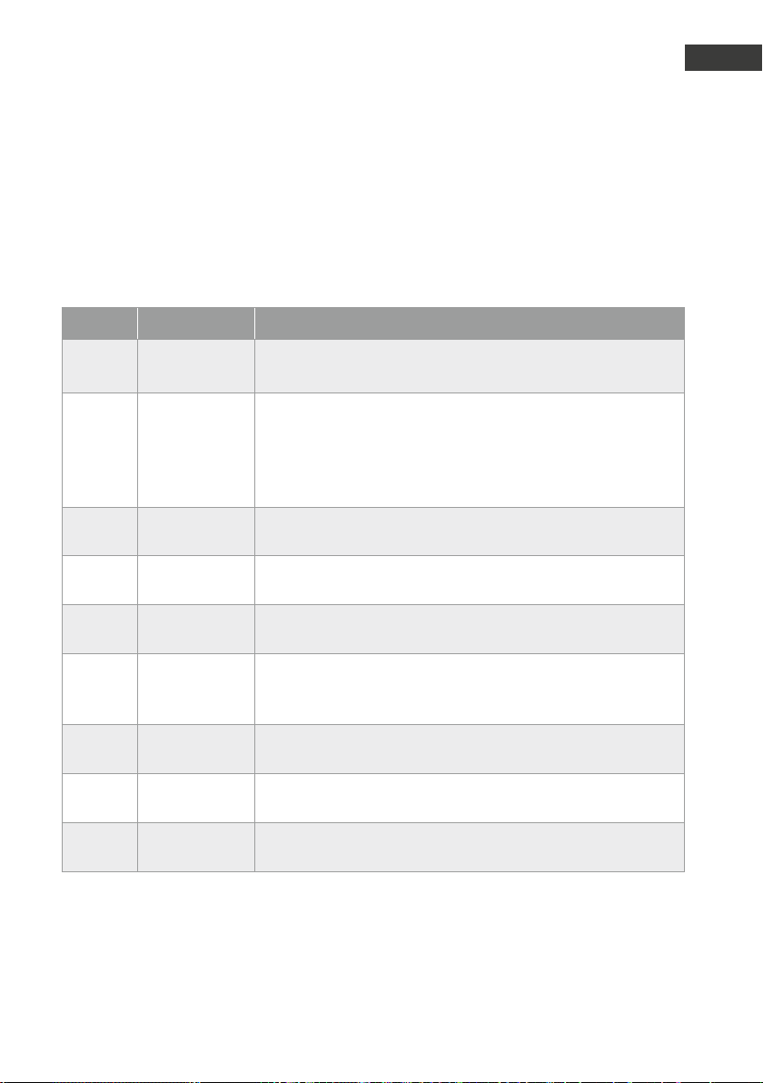
.
Beim Initialisieren wird die Funktionalität der wichtigsten Elektronik-Komponenten überprüft. Wird
dabei ein Fehler festgestellt, so wird statt des normalen hohen Initialisierungs-Pieptons eine Folge
von Pieptönen ausgegeben, die jeweils einem bestimmten Fehler zugeordnet ist. Die Zuordnung
entnehmen Sie der folgenden Tabelle:
Pieptöne Fehler Mögliche Ursachen
D
3 EEprom-Fehler
4 Tastenmatrix-
Fehler
5 Besetztton-
Dekoder-Fehler
6 DTMF-Tondeko-
der-Fehler
7 1kb-EEprom ab
V1.30
8 Mikrofon-Fehler Kompaktgerät: das angeschlossene Mikrofon ist falsch gepolt
9 Mikrofon-Fehler das am MLM-A eines Universalgerätes angeschlossene
10 Mikrofon-Fehler das am MLM-B eines Universalgerätes angeschlossene
11 Mikrofon-Fehler das am MLM-C eines Universalgerätes angeschlossene
EEprom nicht korrekt im dafür vorgesehenen Sockel installiert
▸
EEprom defekt
▸
angeschlossene Taste, Konfigurationstaste oder Tastwahlblock
▸
klemmt oder ist defekt
Anschlusskabel für Taste oder Tastwahlblock ist beschädigt
▸
Störeinstrahlung
▸
Feuchtigkeit auf Platine oder in Anschlussstecker
▸
Besetzton-Dekoder-Baustein ist defekt
DTMF-Tondekoder-Baustein ist defekt
Falsches EEprom, ab V1.30 sind nur noch 2kb-EEproms zulässig
Universalgerät: das am integrierten MLM angeschlossene
Mikrofon ist falsch gepolt
Mikrofon ist falsch gepolt
Mikrofon ist falsch gepolt
Mikrofon ist falsch gepolt
41www.behnke-online.de
Page 42

Anleitung Türstationen a / b Serie 20 / 30 / 40 / 50 / 20-0028A/-0028B
D
FAQ
.
Tür wählt keine oder falsche Rufnummer
Rufnummer aus Auslieferungszustand nicht
▸
neu konfiguriert
Falsche Rufnummer konfiguriert
▸
Türstation hat Konfiguration nicht angenommen
▸
siehe: Türstation lässt sich nicht konfigurieren
Gegenstelle im Haus läutet einmal, keine
▸
Sprachverbindung *2 (2 Sekunden Pause)
vor und hinter die Rufnummer konfigurieren
Türsprechstelle lässt sich aus der Ferne nicht
konfigurieren
Das Telefon mit dem Sie die Türstation konfigu-
▸
rieren sendet keine DTMF-Töne Telefon mit
DTMF-Wahl benutzen
Korrekt in den Konfigurationsmodus mit
▸
**0000 einsteigen
Keine (direkte) Sprachverbindung nach Verbindungsaufbau
a / b-Port prüfen Port in der TK-Anlage muss
▸
als Telefonport generiert sein, nicht als TFE/
Türsprechstelle/FTZ
Gerät initialisiert sich dauerhaft bei Inbetriebnahme
a / b-Port prüfen, falls Leitungsüberwachung
▸
vorhanden ist abschalten, a / b-Port darf nicht
aufgetrennt werden
Namensschild nicht beleuchtet
Spannungsversorgung fehlt
▸
Spannungsversorgung ist verpolt
▸
Verbindung vom Namensschild zur Basiselekt-
▸
ronik überprüfen
Türöffner wird nicht angesteuert
Anschluss des Türöffners prüfen Schließer
▸
verwenden
Spannungsversorgung für Türöffner fehlt
▸
bauseits (nicht mit Behnke Spannungsversorgung parallel)
Telefon sendet keine DTMF-Töne -> siehe: Tür-
▸
station lässt sich nicht konfigurieren
Code zur Türöffnung nicht oder falsch konfigu-
▸
riert (Auslieferungszustand 0#)
Codeeingabe mit # betätigen
▸
Türsprechstelle ohne Funktion
a / b-Port prüfen ggf. messen
▸
Falls Zusatzversorgung angeschlossen, prüfen
▸
ob diese potentialfrei ist
Mehrere Türstationen parallel angeschlossen
▸
jedes Telefon benötigt eigenen analogen
Anschluss und eigene potentialfreie Spannungsversorgung
Schleifenstrom der TK-Anlage ausreichend
▸
muss größer als 20 mA sein
Siehe: technische Daten Türstation
▸
Nach Verbindungsende kein Besetzton sondern
Initialisierung der Sprechstelle
a / b-Port prüfen, es wird kein Besetzton
▸
ausgegeben, zum Gesprächsende muss ein
Besetzton durch die Telefonanlage ausgegeben
werden. Telefonanlage muss zum Verbindungsende einen Besetzton ausgeben.
42 www.behnke-online.de
Page 43

Anleitung Türstationen a / b Serie 20 / 30 / 40 / 50 / 20-0028A/-0028B
Sporadische Rufauslösung bei Türsprechstellen
Zusätzliche Ruftasten angeschlossen, Taster
▸
entfernen, keine Taster parallel schalten
Bei abgesetzter Basiselektronik die Länge der
▸
Tastenanschlussleitung beachten. Diese sind
bei den Daten der entsprechenden Basiselektronik zu entnehmen.
Fremdtaster angeschlossen, Taster auf Tauglich-
▸
keit überprüfen, prellen,Potentialfreiheit, keine
gemeinsame Masse.
Sicherheitscode der Türsprechstelle nicht
bekannt
Hardwarerest nötig
▸
1. Telefonleitung (a / b) entfernen
2. Wenn vorhanden 12V bis 15V Zusatzversorgung entfernen
3. EEpromm entfernen (Bauteil rechts oben auf
der Platine mit links und rechts jeweils vier
Beinen, s. Kapitel „3.1. Anschlusspläne“ ab
Seite 14)
4. Telefonleitung aufstecken und abwarten bis
die Elektronik 3 x piept
5. EEprom (unter angeschlossener a / b-Leitung)
wieder stecken.
6. Für den Reset des Sicherheitcodes die
*-Taste drücken und gedrückt halten bis die
Elektronik mit einem Piepton beginnt. Taste
loslassen.
Für einen kompletten Reset des Gerätes die
#-Taste drücken und gedrückt halten bis die
Elektronik mit einem langen Piepton beginnt.
FAQ
D
Konfigurationswert (z.B. Rufnummer) löschen
Konfigurationsmodus starten
▸
Konfigurationsschritt aufrufen und mit # bestä-
▸
tigen. Der eingestellte Konfigurationswert ist
gelöscht.
43www.behnke-online.de
Page 44

Anleitung Türstationen a / b Serie 20 / 30 / 40 / 50 / 20-0028A/-0028B
D
Technische Daten
.
Anschlussart: analoges Telefonnetz, a / b-Schnittstelle
Energieversorgung: über die a / b-Schnittstelle
Schleifenspannung: 20-70 VDC
Schleifenstrom: 20-60 mA
Zusatzversorgung: 12-15 V= potentialfrei
Behnke Steckernetzteil oder andere Zusatzversorgung in Verbin-
dung mit Behnke DC / DC-Wandler; pro Steckernetzteil eine Behnke
Türstation möglich
Abschluss: Zr nach TBR 21
Erkanntes Rufsignal: nicht genau spezifizierbar, da abhängig von Amplitude, Frequenz
und Dauer des Rufsignals
Erkanntes Besetztsignal: 400-450 Hz sinus
Erkannte Besetztsignaldauer: Signale mit 160-700 ms Ton bzw. 160-700 ms Pause
Zulässige Kabellänge: jeweils maximal 10 m (für MLM A, +MLM B, +MLM C, LS, MIC,
T1undT2) oder jeweils maximal 25 m (für LS, MIC, T1undT2, wenn
kein sonstiges MLM angeschlossen ist)
Wahlverfahren: MFV, 50/50 ms (Ton/Pause)
Eingebaute Relais: 2 Stück (2 Schaltrelais)
Relaisschaltleistung: max. 60 VA 24 W: 0,5 A 120 V~ oder 1 A 24V= (Ohm’sche Last)
Zusatzversorgung auf MLMs: max. Strombelastung 30 mA pro MLM
Speicher: EEprom, nicht flüchtig
IP-Schutzklasse: 54
Betriebstemperatur: -20° bis +50°
Geprüft nach: TBR 21 sowie EG 201 121 (Netzzugang EU-weit) EN 55022, EN55024
(Elektromagnetische Verträglichkeit)
EN60950 (elektrische Sicherheit)
44 www.behnke-online.de
Page 45

.
Anleitung Türstationen a / b Serie 20 / 30 / 40 / 50 / 20-0028A/-0028B
Rechtliche Hinweise
D
1. Änderungen an unseren Produkten, die dem
technischen Fortschritt dienen, behalten wir
uns vor. Die abgebildeten Produkte können im
Zuge der ständigen Weiterentwicklung auch
optisch von den ausgeliefer ten Produkten
abweichen.
2. Abdrucke oder Übernahme von Texten, Abbildungen und Fotos in beliebigen Medien aus
dieser Anleitung – auch auszugsweise – sind
nur mit unserer ausdrücklichen schriftlichen
Genehmigung gestattet.
3. Die Gestaltung dieser Anleitung unterliegt
dem Urheberschutz. Für eventuelle Irrtümer,
sowie inhaltliche bzw. Druckfehler (auch bei
technischen Daten oder innerhalb von Grafiken und technischen Skizzen) übernehmen
wir keine Haftung.
Infos zum Produkthaungsgesetz:
1. Alle Produkte aus dieser Anleitung dürfen
nur für den angegebenen Zweck verwendet
werden. Wenn Zweifel bestehen, muss dies
mit einem kompetenten Fachmann oder unserer Serviceabteilung (siehe Hotline-Nummern)
abgeklärt werden.
2. Produkte, die spannungsversorgt sind (insbesondere 230 V-Netzspannung ), müssen vor
dem Öffnen oder Anschließen von Leitungen
von der Spannungsversorgung getrennt sein.
3. Schäden und Folgeschäden, die durch Eingrif fe oder Änderungen an unseren Produkten
sowie unsachgemäßer Behandlung verursacht
werden, sind von der Haftung ausgeschlossen. Gleiches gilt für eine unsachgemäße
Lagerung oder Fremdeinwirkungen.
4. Beim Umgang mit 230 V-Netzspannung oder
mit am Netz oder mit Batterie betriebenen
Produkten, sind die einschlägigen Richtlinien
zu beachten, z. B. Richtlinien zur Einhaltung
der elektromagnetischen Verträglichkeit oder
Niederspannungsrichtlinie. Entsprechende
Arbeiten sollten nur von einem Fachmann
ausgeführt werden, der damit vertraut ist.
Elektromagnetische
Verträglichkeit
Niederspannungsrichtlinie
5. Unsere Produkte entsprechen sämtlichen,
in Deutschland und der EU geltenden, technischen Richtlinien und Telekommunikationsbestimmungen.
45www.behnke-online.de
Page 46

Anleitung Türstationen a / b Serie 20 / 30 / 40 / 50 / 20-0028A/-0028B
D
Notizen
46 www.behnke-online.de
Page 47

Manual Door intercom devices a / b series 20 / 30 / 40 / 50 / 20-0028A/-0028B
GB
Version 2.3
D Türstationen a / b Serie 20 / 30 / 40 / 50 / 20-0028A/-0028B Seite .... 49
GB Manual Door Intercom Devices a / b series 20 / 30 / 40/ 50 /
20-0028A/-0028B Page ..... 49
FR Portiers téléphoniques a/b Séries 20 / 30 /40 / 50 /
20-0028A/-0028B Page .....86
47www.behnke-online.com
Page 48
GB
Manual Door intercom devices a / b series 20 / 30 / 40 / 50 / 20-0028A/-0028B
GB
Contact
Important Information
Please note that Behnke intercoms and accessories may only be installed and serviced by qualified
electricians, IT and telecommunications technicians who comply with the corresponding norms and
regulations. Before carrying out service and maintenance work, please ensure that the devices are
safely disconnected from the power grid (unplug power supply unit) and are disconnected from any
other network and that all relevant safety regulations will be maintained.
For further legal information, please see page 91.
Information:
For detailed information on our product,
projects and services:
Tel.: +49 (0) 68 41/81 77-700
24-hour service:
Do you need help? Feel free to contact us
24/7. We will be happy to assist you with
any technical questions you may have and
we will also help you getting set-up.
Tel.: +49 (0) 68 41/81 77-777
Telecom Behnke GmbH
Gewerbepark „An der Autobahn“
Robert-Jungk-Straße 3
D-66459 Kirkel
E-mail address and website
[email protected]
www.behnke-online.de
48 www.behnke-online.com
Page 49

Manual Door intercom devices a / b series 20 / 30 / 40 / 50 / 20-0028A/-0028B
Contents
1. Introduction 50
1.1. General Information ..........................................................................................................50
2. Installation 52
2.1. Series 20 / 30 / 40 / 50 (20-0001/-0002/-0010/-0013/-0014/-0016/-0041/-0043) ............... 52
2.2. Mechanical mounting Series 20/30 ..................................................................................54
2.3. Inserting a label ...............................................................................................................57
2.4. Universal devices 20-0005/-0006/-0018/-0026/-0028A/-0028B/-0048 ...........................58
2.5. Series 50 ..........................................................................................................................58
3. Connection 59
Series 20 / 30 / 40 / 50 and 20-0005/-0006/-0018/-0026/-0028A/-0028B/-0048 ............59
▸
3.1. Wiring diagrams ............................................................................................................. 60
Compact electronics 20-0001/-0002/-0010*/-0013/-0014/-0016/-0041/-0043 ................ 60
▸
Universal electronics 20-0005 ........................................................................................ 61
▸
Universal electronics 20-0006/-0018/-0026 (up to fourth quarter of 2018) .......................62
▸
Universal electronics 20-0006/-0018/-0026 (from first quarter of 2019 onwards) .............63
▸
Universal electronics 20-0048 (up to fourth quarter of 2018) ........................................... 64
▸
Universal electronics 20-0048 (from first quarter of 2019 onwards) ..................................65
▸
Lift emergency phone 20-0028A
▸
(up to firmware version BT MA 1.63, delivered up to the third quarter of 2018) ..................... 66
Lift emergency phone 20-0028A
▸
(up to firmware version BT MA 1.63, delivered up to the second quarter of 2019) ................. 68
Lift emergency phone 20-0028B
▸
(up to firmware version BT MA 1.64, from the second quarter of 2019) ..................................70
GB
4. Configurations and Set-up 72
5. Operation 82
6. Extended operation 83
6.1. Control options during voice calls .....................................................................................83
6.2. Automatic acoustic setting with ##* function (V1.51 or later) ............................................85
6.3. Call answering when redialling / group calling is active (configuration step 20 active) ...... 86
7. Error table 87
8. FAQ 88
9. Technical Specifications 90
10. Legal Information 91
49www.behnke-online.com
Page 50

GB
Manual Door intercom devices a / b series 20 / 30 / 40 / 50 / 20-0028A/-0028B
GB
Introduction
.
1.1. General Information
Please note the following features when installing and setting up your Behnke door intercom
device:
Operation with an analogue extension to a
▸
telephone system, an analogue landline connection or other a / b ports.Note: When using
other a / b ports, please make sure that you
fulfil the corresponding requirements of an
analogue extension, such as busy tone, DTMF
transparency, etc.
The operation is possible without an addi-
▸
tional power supply.
The door intercom devices work in full-duplex
▸
mode and can be switched to semi-duplex
and simplex (may require an additional power
supply).
Installation requirements
The perfect installation height for your device
▸
is a position that enables operating the door
intercom at a distance of 30-50 cm with a
person standing in front of the device being
able to easily speak into the microphone.
Please keep the largest possible distance
▸
between
microphone and speaker. This will give you
the best possible voice quality in full-duplex
mode.
Modules for reverse-side mounting (=mount-
▸
ing behind an existing wall) require sufficiently large slits for sound to enter in front
of the microphone and for sounds to exit
from the speaker (at least 75% of the speaker
membrane surface for sound to exit or 75% for
the sound to enter the microphone housing).
Please see dimension drawings on www.
behnke-online.de/downloads
Please always mount a reverse-side mounting
▸
module in a flush way ( without distance)
behind your front wall and do not forget to
install the included seal between front wall
and mounting module.
Outside mounting
When using your door intercom device on
▸
a weather side, the Series 20 and 30 door
intercom devices should be mounted in-wall
with a rain protection cover or on-wall with a
wall-mounted housing (Please always ensure
the included seal is correctly put in place).
All in-wall mounted door intercom devices
▸
need to be well sealed against rain water
entering into the housing, esp. with an
uneven underground (e.g. using silicone).
Please leave the centre of the bottom edge of
your door intercom device open to serve as
a water drain. When using cover panels, the
cover panel needs to be sealed with a suitable sealing agent against the in-wall housing
or the level surface for cavity wall mounting.
For mounting in steles by third-party provid-
▸
ers, appropriate action needs to be taken to
prevent condensation water from forming
inside the stele.
Sealings
To protect your device against dampness,
please make sure the included sealings have
been put in place correctly when installing
your door intercom device. The sealing must be
correctly placed onto the frame of the in-wall
housing or the on-wall housing! In-wall hous-
50 www.behnke-online.com
Page 51

Manual Door intercom devices a / b series 20 / 30 / 40 / 50 / 20-0028A/-0028B
Introduction
GB
ings are available for installation in masonry
or in drywall. You will find the most important
mounting information on a sticker inside the
respective housing.
Please also order the mounting set for mounting
in drywall (order # 20 -5216 0).
Distance from the electronics connection to
buttons,
speaker and microphone (Please note: This is
only possible with the following electronics)
20-0005: max. 25 m
▸
20-0006/-0018/-0026/-0028A/-0028B and
▸
20-0048: Max. 25m for one button, 12.5m for
two buttons, 8.5m for three buttons*
*If the cable lengths exceed the values stated
above, the 40-0006 basic electronics (triphone)
can be used.
Wiring for mounting with the electronics installed in a separate installation
(20-0005/-0006/-0018/-0026/-0028A/-00
28B/-0048)
Use Behnke patch cables or screened wires
▸
for mounting, e.g. IY-ST-Y or AY-ST-Y, and
connect the wire screen to the 12 V– termi-
nal at the door intercom device (not to the
grounding).
Please note: Guide the wire screen in the
front panel area as closely as possible to the
speakers, microphone, and button. Isolate it
right there.
short intervals using a cleaning agent that is
appropriate for the material in question. This
prevents early ageing and patina formation on
the surface.
Original Behnke components
Please do not use any other parts but original
Behnke components or spare parts – this also
applies to plug-in power supply units! This will
guarantee an intercom operation free from
interference. Please mount and install the
electronics only in the provided housings. If a
third-party housing or a housing other than the
one provided for mounting is used, we cannot
guarantee functioning and approval of your
door intercom.
Configuration and Set-up
The door intercom devices can be set up
locally at the basic electronics or remotely via
telephone (DTMF signal = tone dial). All door
intercom devices are delivered with a standard
pre-configuration.
Prescriptions
Please adhere to the relevant prescriptions for
the installation of communications and electronic systems!
Maintenance and Care
You have chosen high-quality Behnke products with front panels made from various
materials. Regardless of the material, all front
panels require regular cleaning in sufficiently
51www.behnke-online.com
Page 52

GB
Manual Door intercom devices a / b series 20 / 30 / 40 / 50 / 20-0028A/-0028B
GB
Installation
.
Please note:
Dimension and installation drawings are available at www.behnke-online.de/bemassung
2.1. Series 20 / 30 / 40 / 50 (20-0001/-0002/-0010/-0013/- 0014/-0016/- 0041/- 0043)
Please note: When inserting the function modules, please take note of the direction of the
aluminium brushing both for aesthetic reasons
and for dampness protection and also mind the
anti-twist protection of the modules! The door
intercom device may only be installed with a
suitable frame. Prevent any condensation from
forming inside the housing! Mount the door
intercom device so no water will remain on the
front cover. When mounting your door intercom
into a third-party column, please pay special
attention to the column ventilation.
When installing the electronics in a locally
dispatched way, please replace the module
housing with open counterplate for the respective front frame (use button extension 20-9305,
do not extend the connection wires yourself,
max 3m).
Connect the wires in the following sequence:
1. Connect the buttons (RT) ▸ to the MQS plugs
from T1 to T8 marked with the yellow ring
T1 (button 1)= configuration step 21
...
T8 (button 8)= configuration step 28
When using third-party buttons, please
ensure that the button meets the corresponding approval requirements. “Bell buttons”
usually do not meet these requirements.
(see Seite 57 ) The buttons need to be
potential-free.
2. Connect the speakers (LS) ▸to the plug
marked with the blue ring
3. Connect the microphone (Mic) ▸ to the plug
marked with the white ring
4. Number keypad ▸white 12-pin socket
5. Camera ▸ black 4-pin socket (FBAS video
signal)
6. Please connect the door opener to relay 1,
where necessary. (Relay = a potential-free
contact: only switches the circuit to open the
door, but does not provide electric voltage.
Please use the closing contact to do so). The
door opener requires its own circuit. Relay 2 is
available for additional switch functions.
52 www.behnke-online.com
Page 53

Manual Door intercom devices a / b series 20 / 30 / 40 / 50 / 20-0028A/-0028B
7. If required, connect 12-15 V= (potential-free;
use Behnke plug-in power supply 20-9585).
Required for lighting, integrated heating, and
additional amplifier; not required for tele-
phone operation including all functions. Spe-
cial functions, such as camera, display, voice
messages, timer control may need additional
electronics and an additional power supply.
If you use multiple door intercom devices,
please always ensure a galvanic isolation of
the additional power supply. Please note:
The concurrent operation of multiple devices
using one power supply unit without DC/DC
converter is not permitted.
8. Connect the telephone line to: a / b line of the
analogue extension of a telephone system,
analogue landline connection or other a / b
ports. After connecting the telephone line,
you will hear a long beep indicating the
operational readiness of the door intercom
device (=initialisation). The door intercom
device is now ready for set-up. Please note:
The devices must not be operated in parallel
via an a/b line.
Installation
GB
Please put unused cables into the module housing with the open end (connector) facing down.
Doing so will prevent moisture from entering
into the connector. Now put the electronics box
on top of the module housing.
53www.behnke-online.com
Page 54

GB
Manual Door intercom devices a / b series 20 / 30 / 40 / 50 / 20-0028A/-0028B
GB
Installation
2.2. Mechanical mounting Series 20/30
Insert the function modules into the front frame
Bridges
Illumination 12 V=
(Line coming from the
basic electronics)
Insert the modules into the frame from the rear.
LS
RT
RT
RT
Mic
Connection of the key illumination for Behnke keys (optional
illuminated keys)
T
T
T
Illumination 12V=
12V-bridges to illuminate
the label positions
Function modules into the front frame
LP
RT
T
RT
T
Mic
RT
T
When inserting the modules, please make sure to maintain the anti-twist protection and also have
the modules “click” audibly into position.
54 www.behnke-online.com
Page 55
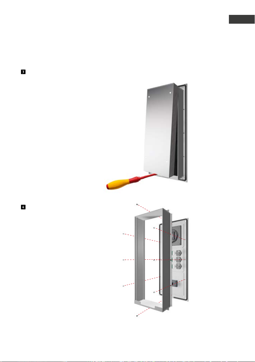
Manual Door intercom devices a / b series 20 / 30 / 40 / 50 / 20-0028A/-0028B
Remove the electronics box from the module housing
Installation
GB
Fix the module housing
*
for remote mounting, please use the open counterplate.
*
55www.behnke-online.com
Page 56
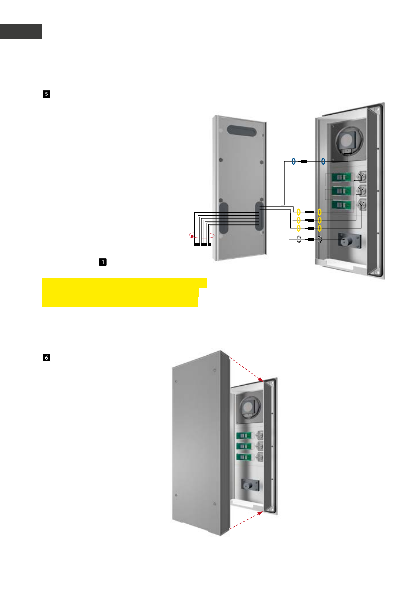
GB
Manual Door intercom devices a / b series 20 / 30 / 40 / 50 / 20-0028A/-0028B
GB
Installation
Connect the ribbon cable to the installation
components (speaker, microphone, buttons
etc.)
Plug connection for the branch line
Series 20, 30, 50:
LP (blue) ▸ speaker
Mic (white) ▸ microphone
T1 bis T8 (yellow) ▸ button 1 to 8
12-pin plug ▸ key pad
HPI Contact (white) ▸ label field
(cf. also section )
Please note: Connect the available components
using the ribbon cable. Use a cable tie to connect the wires not in use (plugs facing down).
Electronics box
T
T1
T
T2
T
T3
Module housing
Then clip the electronics box
back onto the module housing.
56 www.behnke-online.com
Page 57

Manual Door intercom devices a / b series 20 / 30 / 40 / 50 / 20-0028A/-0028B
2.3.
Inserting a label
Labels are included with the basic electronics. Labelling software can be found here:
www.behnke-online.de/downloads/beschriftungshilfen
Installation
GB
Default status
Release the label field by pressing
the on the right side
and remove with a twist
Insert the label from the left
Put the label field in from the left
and click it back into place
Done!
57www.behnke-online.com
Page 58
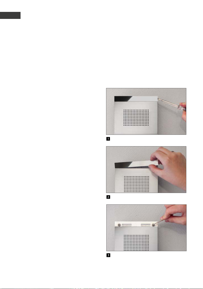
GB
Manual Door intercom devices a / b series 20 / 30 / 40 / 50 / 20-0028A/-0028B
GB
Installation
2.4. Universal devices 20-0005/-0006/
-0018/-0026/-0028A/-0028B/-0048
1. Please mount the universal electronics in a
weatherproof location inside the provided
housing and please connect the electronics to
the interface unit(s).
2. Please take notice of the advice on wiring,
distances and wire lengths on Seite 51.
3. Connected buttons need to comply with
the requirements stated in NE60950 for
communication circuits (TNV). Standard “bell
buttons” usually do not meet these requirements, please use Behnke buttons where
required!
2.5. Series 50
Series 50 door intercom devices come
pre-assembled. To mount these door intercom
devices, please follow the steps shown here.
For advice on electric mounting, please see the
following pages.
Unclip the stainless steel strip
Remove the stainless steel strip
Connect and fix the door intercom device
58 www.behnke-online.com
Page 59

Manual Door intercom devices a / b series 20 / 30 / 40 / 50 / 20-0028A/-0028B
.
Series 20 / 30 / 40 / 50 and 20-0005/-0006/
-0018/-0026/-0028A/-0028B/-0048
Connection
GB
Advice on the connection of 20-0005/-0006/
-0018/-0026/-0028A/-0028B/-0048: Please
start by connecting the speaker, the microphone, and the buttons and make sure to maintain a maximum possible distance between the
speaker, the microphone, the buttons, and the
electronics. Please take notice of the advice on
wiring, distances and wire lengths from Seite
51. Important: Buttons may not use the same
return wire (mass)!
1. Please connect the door opener to relay 1,
where necessary. Relay = a potential-free
contact: only switches the circuit to open the
door, but does not provide electric voltage
(use a closing contact instead). The door
opener requires its own circuit. Relay 2 is
available for additional switch functions.
2. If required, connect 12-15 V= (potential-free
– use Behnke plug-in power supply 20-9585)
Required for lighting, integrated heating,
and integrated additional amplifier; not
required for telephone operation including all
functions. Special functions, such as camera,
display, voice messages, timer control may
need additional electronics and an additional
power supply. For multiple door intercom
devices, please always ensure a galvanic isolation of the additional power supply. Please
note: The devices must not be operated in
parallel to their additional power supply.
3. Connect the telephone line to: a / b line of the
analogue extension of a telephone system,
analogue landline connection or other a / b
ports. After connecting the telephone line,
you will hear a long beep indicating the
operational readiness of the door intercom
device (=initialisation). The door intercom
device is now ready for set-up. Please note:
The devices must not be operated in parallel
via an a/b line.
59www.behnke-online.com
Page 60

GB
Manual Door intercom devices a / b series 20 / 30 / 40 / 50 / 20-0028A/-0028B
GB
Connection
Please note: You can find further
configuration steps from page 72 onwards.
3.1. Wiring diagrams
Compact electronics 20-0001/-0002/-0010*/-0013/-0014/-0016/-0041/-0043
Main board
Connection
board
Connection for
additional boards
EEprom
Master CPU
Internal configuration key-
board
Heating resistor
Connector for lighting (only
required for modules with
lighting)
Flat ribbon line for connect-
ing modules with buttons,
speakers, microphone, etc.
Alarm input only for turning
off the Behnke wide angle
IP camera with app function
Relay 2 only for turning on
the Behnke wide angle IP
camera with app function
Earthing
Telephone line
Main analogue connection or analogue
extension of a telephone system
Wire a
Wire b
Additional power supply
potential-free voltage
e.g. from a Behnke power supply unit
12 - 15 V =
Relay 1
Relay switch power: max. 60 VA/24 W:
0,5 A 120 V~ or 1A 24V=
* Connector for 20-0010 cannot be removed
–
+
Rest contact Make contact
Control contact Control contact
Make contact Rest contact
Video output
only connected with one module
with camera
Video mass
Video signal
Alarm input
–
6 - 24 V =
+
Relay 2
Relay switching power: max. 60 VA 24 W
0.5 A 120 V~ or 1A 24V=
60 www.behnke-online.com
Page 61
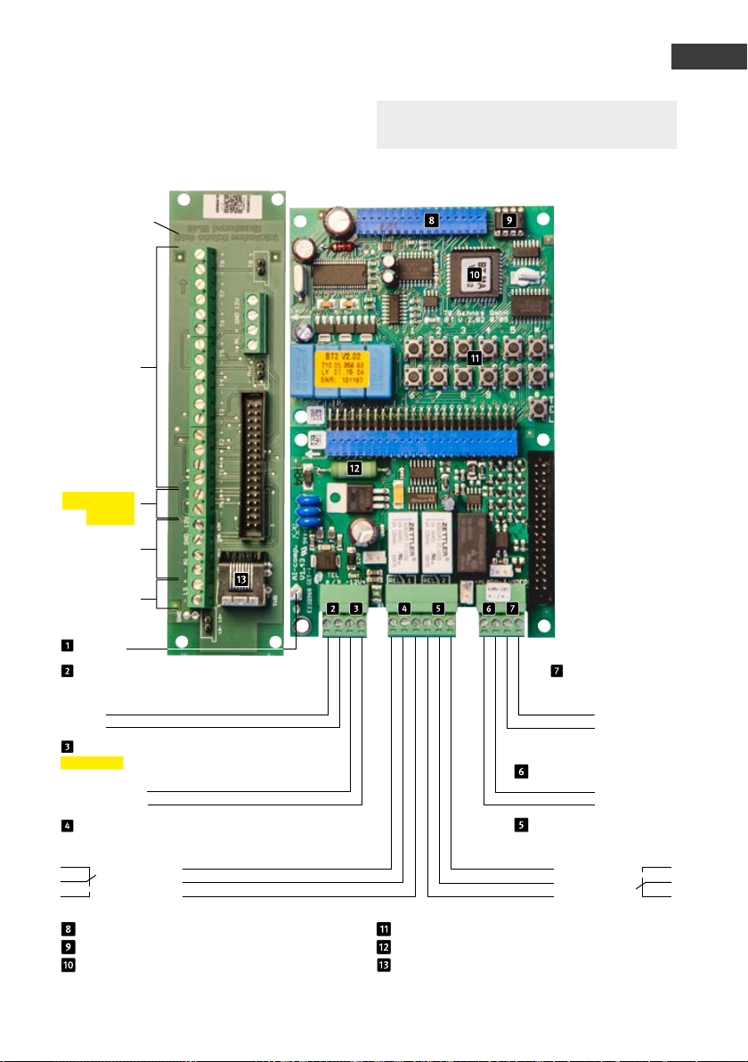
Universal electronics 20-0005
Sub circuit
board *
Suitable
Installation
material for
adaptation of
speaker, micro-
phone and buttons
at the door: branch-
off box 20-9251
Clamps
buttons 1 to 8
potential-free
buttons, max. 25 m
cable length
(cf. Seite 50)
(configuration
steps 21 to 28)
Microphone
(Maintain the
polarity!)
not in use
Manual Door intercom devices a / b series 20 / 30 / 40 / 50 / 20-0028A/-0028B
Connection
Please note: You can find further
configuration steps from page 72 onwards.
GB
Speakers
Earthing
Telephone line
Main analogue connection or
analogue extension of a telephone system
Wire a
Wire b
Additional power supply
potential-free voltage
e.g. from a Behnke power supply unit
12 - 15 V =
Relay 1
Relay switch power: max. 60 VA/24 W:
0,5 A 120 V~ or 1A 24V=
–
+
Rest contact
Control contact
Make contact
Connection for additional boards
EEprom
Master CPU
Video output
only connected with a
module with camera
Video mass
Video signal
Alarm input
–
6 - 24 V =
+
Relay 2
Relay switching power: max. 60 VA
24 W 0.5 A 120 V~ or 1A 24V=
Make contact
Control contact
Rest contact
Internal configuration keyboard
Heating resistor
Connection socket for number keypad max.
25 m connection cable 20-9308 (3 m)
61www.behnke-online.com
Page 62
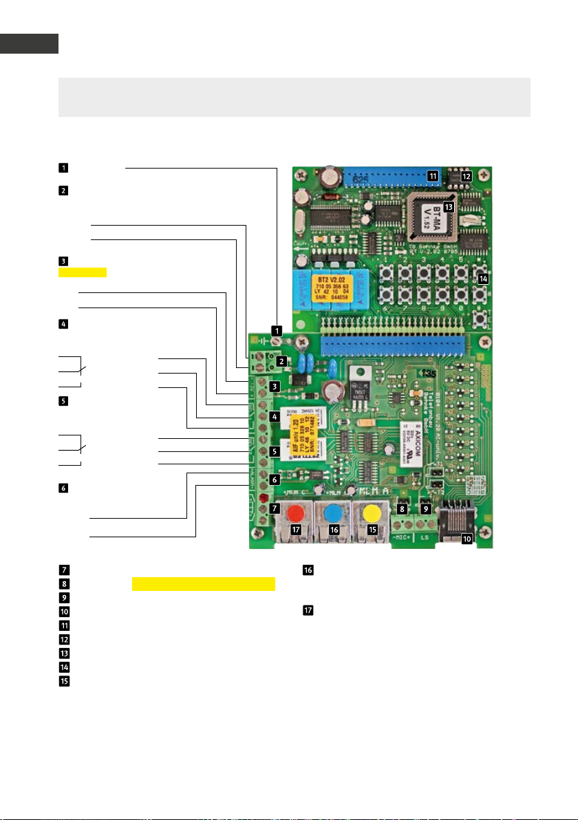
GB
Manual Door intercom devices a / b series 20 / 30 / 40 / 50 / 20-0028A/-0028B
GB
Connection
Please note: Please compare your connection boards of the delivered device/rep. kit to the con-
nection boards in the picture. You can find further configuration steps from page 72 onwards.
Universal electronics 20-0006/-0018/-0026 (up to fourth quarter of 2018)
Grounding
Telephone line
Main analogue connection or analogue
telephone extension
Wire a
Wire b
Additional power supply
potential-free voltage, e.g. from a
Behnke plug-in power supply
–
12 V - 15 V=
+
Relay 1
Relay switch power: max. 60 VA/24 W:
0.5 A 120 V~ or 1A 24V=
Rest contact
Control contact
Operating contact
Relay 2
Relay switch power: max. 60 VA
24 W 0.5 A 120 V~ or 1A 24V=
Rest contact
Control contact
Operating contact
Alarm input
Potential-free voltage, e.g. from
a Behnke power supply unit
–
6 - 24 V =
+
Pushbutton 2 (potential-free closing contact)
Microphone (please maintain the polarity!)
Speakers
Number keypad
Connection for additional boards
EEprom
MLM B (Additional MLM) – Microphone /
Speaker module (configuration
step 23 / button 3)
MLM C (Additional MLM) – Microphone /
Speaker module (configuration
step 24 / button 4)
Master CPU
Internal configuration keyboard
MLM A (Main MLM) – Microphone /
Speaker module (configuration
step 22 / button 2)
Please note: When connecting multiple MLMs, the maximum distance between MLM and basic electronics is decreased:
1 MLM = 25 m / 2 MLMs = 12.5 m each / 3 MLMs = 8.5 m each
Suitable installation material for adaptation of speaker, microphone and buttons at the door: Branch-off box 20-9208
alternatively patch cable 20-9309
Telephone number configuration
Yellow: Configuration step 22
Blue: Configuration step 23
Red: Configuration step 24
62 www.behnke-online.com
Page 63

Manual Door intercom devices a / b series 20 / 30 / 40 / 50 / 20-0028A/-0028B
Connection
Please note: Please compare your connection boards of the delivered device/rep. kit to the con-
nection boards in the picture. You can find further configuration steps from page 72 onwards.
Universal electronics 20-0006/-0018/-0026 (from first quarter of 2019 onwards)
Grounding
Telephone line
Analogue landline connection or analogue
telephone extension
Wire a
Wire b
Relay 1
Relay switch power: max. 60 VA/24 W:
0,5 A 120 V~ or 1A 24V=
Operating contact
Control contact
Rest contact
Relay 2
Relay switch power: max. 60 VA
24 W 0.5 A 120 V~ or 1A 24V=
Operating contact
Control contact
Rest contact
Additional power supply
potential-free voltage e.g. from
a Behnke power supply unit
–
12 V - 15 V=
+
GB
Alarm input
–
6 - 24 V =
+
Not used in this device
Pushbutton 1 + 2 (potential-free closing
contact)
Microphone (please maintain the polarity!)
Speakers
Number keypad
Connection for additional boards
{
MLM B (Additional MLM) – Microphone /
Speaker module (configuration
step 23 / button 3)
MLM C (Additional MLM) – Microphone /
Speaker module (configuration
step 24 / button 4)
EEprom
Master CPU
Internal configuration keyboard
MLM A (Main MLM) – Microphone /
Speaker module (configuration
Telephone number configuration
Yellow: Configuration step 22
Blue: Configuration step 23
Red: Configuration step 24
step 22 / button 2)
Please note: When connecting multiple MLMs, the maximum distance between MLM and basic electronics is decreased:
1 MLM = 25 m / 2 MLMs = 12.5 m each / 3 MLMs = 8.5 m each
Suitable installation material for adaptation of speaker, microphone and buttons at the door: Branch-off box 20-9208
alternatively patch cable 20-9309
63www.behnke-online.com
Page 64

GB
Manual Door intercom devices a / b series 20 / 30 / 40 / 50 / 20-0028A/-0028B
GB
Connection
Please note: Please compare your connection boards of the delivered device/rep. kit to the con-
nection boards in the picture. You can find further configuration steps from page 72 onwards.
Universal electronics 20-0048 (up to fourth quarter of 2018)
Additional
supply
*
T
Speaker to LS+ / - on additional amplifier
up to cf. universal electronics
20-0006 / 20-0018 / 20-0026 on page 62
T
Telephone number configuration
Yellow: Configuration step 22
Blue: Configuration step 23
Please note: Please note the cable lengths on
Seite 50!
*Suitable installation material for adaptation of speaker, microphone and buttons at the door: Branch-off box 20-9208 alternatively
patch cable 20-9309
64 www.behnke-online.com
TT
CarsLorries
Page 65

Manual Door intercom devices a / b series 20 / 30 / 40 / 50 / 20-0028A/-0028B
Connection
Please note: Please compare your connection boards of the delivered device/rep. kit to the con-
nection boards in the picture. You can find further configuration steps from page 72 onwards.
Universal electronics 20-0048 (from first quarter of 2019 onwards)
GB
Additional
supply*
Important: Maintain the
polarity
to
*
T
Speaker to LS+ / - on additional amplifier
up to cf. universal electronics
20-0006 / 20-0018 / 20-0026 on page 63
Telephone number configuration
Yellow: Configuration step 22
Blue: Configuration step 23
Please note: Please note the cable lengths on
Seite 50!
*Suitable installation material for adaptation of speaker, microphone and buttons at the door: Branch-off box 20-9208 alternatively
patch cable 20-9309
**potential-free voltage, e.g. from a Behnke power supply unit
TTT
LorriesCars
65www.behnke-online.com
Page 66
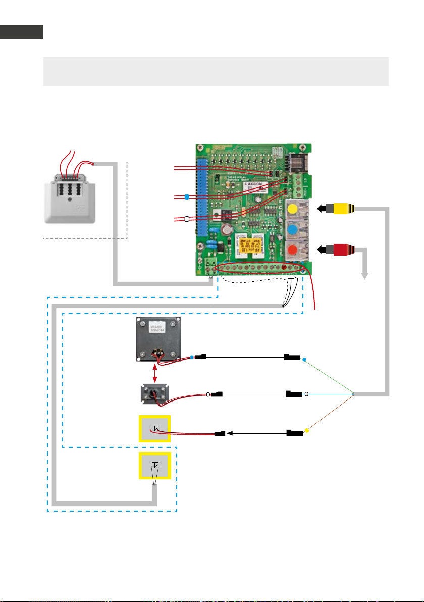
Manual Door intercom devices a / b series 20 / 30 / 40 / 50 / 20-0028A/-0028B
GB
a / b series 20 / 30 / 40 / 50 / 20-0028A/-0028B door intercom manual
GB
D
Connection
Connection
Please note: Please compare your connection boards of the delivered device/rep. kit to the con-
nection boards in the picture. You can find further configuration steps from page 72 onwards.
Lift emergency phone 20-0028A (up to firmware version BT MA 1.63, delivered up to the third quarter of 2018)
Analogue landline connection, analogue extension of a telephone system or GSM gateway
To the button
in the cover
To the speaker
in the cover
To the microphone
in the cover
Travelling cable
Built-in speakers
20-9200 to 20-9202
Distance between speakers
!
and microphone must be at
least 15 cm
Built-in microphone
Alternative
20-9204
Emergency call button
in the cabin
Alternative:
Emergency call
button (T2) in the
cabin directly at the
lift emergency hone
above screened cable
T1
Yellow patch cable
20-9309
Red patch cable
20-9302
Cable screen
(Mass)
T2
Emergency call button
- Must be potential-free
- Normally configured closing contact (default)
- Optional opening contact (configuration step 970)
Alternative for non-isolated button (1.40 or later):
- Connect button with 6 - 24V at the alarm input minding the polarity
- Set configuration step 17 to value “6” (trigger like T2)
Please note: if the button is connected via the control cabinet, an intermediate relay must be inserted into the emergency phone.
To the outside door
intercom device
under the cabin
20-9230
For terminal row
assignment see
also page 62
T
Standard
66 www.behnke-online.com
Page 67

Manual Door intercom devices a / b series 20 / 30 / 40 / 50 / 20-0028A/-0028B
a / b series 20 / 30 / 40 / 50 / 20-0028A/-0028B door intercom manual
Connection
Connection
Quick set-up (code, value, confirmation)
(Always check with the operator)
▸ Connect the telephone line: during the initialisation,
there is a high-pitch beep for approx. 10 seconds.
▸ Enter set-up mode: *, 0000
▸ Enter telephone numbers
▸ first telephone number: 21, telephone number, #
▸ second telephone number: 22, telephone number, #
▸ third telephone number: 23, telephone number, #
▸ up to the ninth telephone number: 29, telephone number, #
▸ Activate group calling,
number of telephone numbers to be dialled: 20, 1 to 9, #
(Please note: the call reception terminal station
has to acknowledge the call with a DTMF tone)
▸ Volume control (optimum setting = 7) 06,
1 97
, #
▸ Non-isolated button at alarm input: 17, 6, #
▸ Activation of the 900-parameters: 900, 1, #
▸ Echo suppressor damping (remove acoustic feedback): 911, 15 to 20, #
▸ Microphone level: 913, 1 to 7, #
▸ Cabin button: Closing contact (standard) 970, 0, #
▸ Cabin button: Opening contact 970, 1, #
(Please note: this configuration section must be activated
before connecting the opening contact)
▸ Deactivation of the 900-parameters: 900, 0, #
▸ Exit set-up mode: *
GB
D
67www.behnke-online.com
Page 68
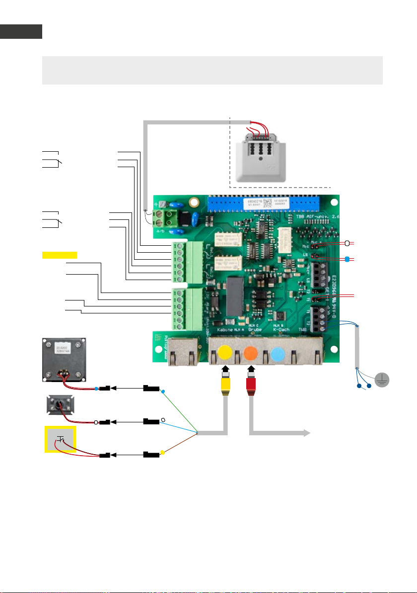
GB
GB
Connection
Please note: Please compare your connection boards of the delivered device/rep. kit to the con-
nection boards in the picture. You can find further configuration steps from page 72 onwards.
Lift emergency phone 20-0028A (up to firmware version BT MA 1.63, delivered up to the second quarter of 2019)
Manual Door intercom devices a / b series 20 / 30 / 40 / 50 / 20-0028A/-0028B
Relay 1
Relay switch power:
max. 60 VA 24 W 0.5 A 120 V~
or 1A 24V=
Operating contact
Control contact
Rest contact
Relay 2
Relay switch power:
max. 60 VA 24 W 0.5 A 120 V~
or 1A 24V=
Operating contact
Control contact
Rest contact
Additional
power supply
potential-free voltage
–
12 V - 15 V=
+
Alarm input
–
6 - 24 V =
+
Not used in this device
Built-in speakers
20-9200 to 20-9202
Distance between
!
speakers and microphone
must be at least 15 cm
Built-in microphone
20-9204
Emergency call button
in the cabin
Emergency call button
- Must be potential-free
- Normally configured closing contact (default)
- Optional opening contact (configuration step 970)
Alternative for non-isolated button (1.40 or later):
- Connect button with 6 - 24V at the alarm input minding the polarity
- Set configuration step 17 to value “6” (trigger like T2)
Please note: if the button is connected via the control cabinet, an intermediate relay must be inserted into the emergency phone.
Travelling cable
{
T
Analogue landline connection,
analogue extension of a telephone
system or GSM gateway
*
Red patch cable
Yellow patch cable
20-9309
20-9302
*Connection plug to
the basic electronics
(required for operation)
To the microphone
in the cover
To the speaker
in the cover
T1
To the button
in the cover
Alternative to T2*
To the outside
door intercom device
under the cabin 20-9230A
Screen
68 www.behnke-online.com
Page 69

Manual Door intercom devices a / b series 20 / 30 / 40 / 50 / 20-0028A/-0028B
Connection
Quick set-up (example) (code, value, confirmation)
(Always check with the operator)
▸ Connect the telephone line:
during the initialisation, there is a high-pitch beep for approx. 10 seconds.
▸ Enter set-up mode: *, 0000
▸ Enter telephone numbers
▸ first telephone number: 21, telephone number, #
▸ second telephone number: 22, telephone number, #
▸ third telephone number: 23, telephone number, #
▸ up to the ninth telephone number: 29, telephone number, #
▸ Activate group calling,
number of telephone numbers to be dialled: 20, 1 to 9, #
(Please note: the call reception terminal station
has to acknowledge the call with an DTMF tone)
▸ Volume control (optimum setting = 7) 06,
1 97
, #
▸ Non-isolated button at alarm input
(button carries a tension of 6 volts= to 24 volts=): 17, 6, #
▸ Activation of the 900-parameters: 900, 1, #
▸ Echo suppressor damping (remove acoustic feedback): 911, 15 to 20, #
▸ Microphone level: 913, 1 to 7, #
▸ Cabin button: Closing contact (is expected to be standard for 20-0028A) 970, 0, #
▸ Cabin button: Opening contact (change configuration step, closing contact standard) 970, 1, #
(Please note: this configuration section must be activated
before connecting the opening contact)
▸ Deactivation of the 900-parameters: 900, 0, #
▸ Exit set-up mode: *
GB
69www.behnke-online.com
Page 70
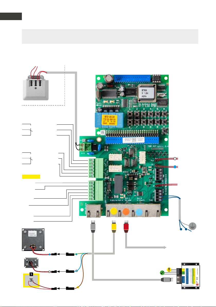
GB
Manual Door intercom devices a / b series 20 / 30 / 40 / 50 / 20-0028A/-0028B
GB
Connection
Please note: Please compare your connection boards of the delivered device/rep. kit to the con-
nection boards in the picture. You can find further configuration steps from page 72 onwards.
Lift emergency phone 20-0028B (up to firmware version BT MA 1.64, from the second quarter of 2019)
Analogue landline connection, analogue extension of a
telephone system or GSM gateway
Relay 1
Relay switch power: max. 60 VA/24 W:
0,5 A 120 V~ or 1A 24V=
Operating contact
Control contact
Rest contact
Relay 2
Relay switch power: max. 60 VA
24 W 0.5 A 120 V~ or 1A 24V=
Operating contact
Control contact
Rest contact
Additional
power supply
potential-free voltage
e.g. from a Behnke power supply unit
–
12 V - 15 V=
+
Alarm input
–
6 - 24 V =
+
Pictogram control
–
10 - 35 V =
+
Distance between speakers
and microphone must be
at least 15 cm
Built-in microphone
20-9204
Emergency call button
in the cabin
Travelling cable
To the microphone
in the cover
To the speaker
in the cover
T1
To the button
in the cover
Alternative to T2*
Grey patch cable
20-9329
to the on-site pictograms.
Please note the technical specifications
of the on-site pictograms.
T
Patch cable CAT 5 max. 10m
To the outside
Red patch cable
20-9302
Yellow patch cable
20-9309
intercom station
under the cabin 20-9230
Alternative: Front cover
with pictogram 22-9416
Screen
70 www.behnke-online.com
Page 71

Manual Door intercom devices a / b series 20 / 30 / 40 / 50 / 20-0028A/-0028B
Connection
Quick set-up (example) (code, value, confirmation)
(Always check with the operator)
▸ Connect the telephone line:
during the initialisation, there is a high-pitch beep for approx. 10 seconds.
▸Enter set-up mode: *, 0000
(0000 = security code in default setting)
▸Delay/hold button (in seconds): 04,
▸Volume (volume level 1-9): 06,
1 93
1 97
, #
, #
▸Activate group calling (max. 9): 20, 1-9, #
(number of telephone numbers to be dialled)
▸ first telephone number: 21, 1. Telephone number, #
▸second telephone number: 22, 2. Telephone number, #
▸third telephone number: 23, 3. Telephone number, #
▸up to the ninth telephone number: 29, 9. Telephone number, #
(Please note: The receiver has to acknowledge the emergency call
with a DTMF tone/ any button)
▸Enable extended set-up: 900, 1, #
▸Echo suppressor damping: 911, 15-20, #
▸Reduces the feedback susceptibility)
▸Transmission signal amplification (microphone 1-7): 913, 4, #
▸Receive signal amplification (speakers 1-7): 914, 4, #
▸Routine call every 3 days on target telephone number x: 9921, 3*x, #
▸Endlessly repeat routine call, even if not acknowledged: 9922, 0, #
▸Disable extended set-up: 900, 0, #
▸Exit set-up mode: *
GB
71www.behnke-online.com
Page 72
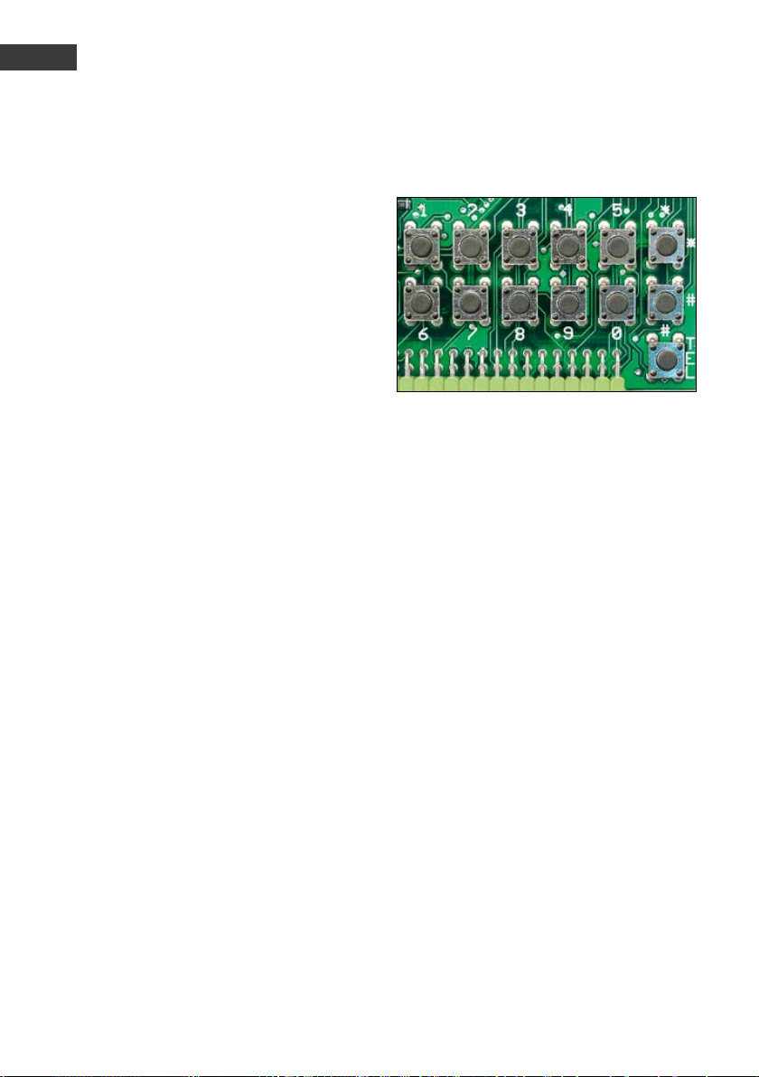
GB
Manual Door intercom devices a / b series 20 / 30 / 40 / 50 / 20-0028A/-0028B
GB
Configurations and Set-up
.
-
The set-up can be performed directly at the door
intercom device via the internal configurations
keypad or remotely via a telephone with DTMF
dialling. On door intercom devices that come
with number keypads you may also use these
for configuration purposes. To enter set-up
mode, you need to enter a 4-digit security code.
The different settings are changed via configuration step codes with an individual code for each
function to be set.
Enter set-up mode
Locally from your door intercom
Press the * key (on the internal configurations
▸
keypad or from a number keypad)
[beep]
Enter the security code (default: 0 0 0 0)
▸
[beep] [beep]
Remotely using a telephone with DTMF dialling
Call your door intercom
▸
The device will answer the call with a [beep]
▸
Press the * key twice after the beep sound.
▸
[beep]
Enter the security code
▸
(default: 0 0 0 0)
[beep] [beep]
Exit set-up mode:
Press the * key or after 30 seconds of inac-
▸
tivity.
Set-up examples directly at the
intercom:
*0000 Enter Set-Up
10 Code to open the door #
21 Telephone number shall dial button 1 if any
button is pressed #
:
28 Telephone number shall dial button 8 if any
button is pressed #
* Exit Set-Up
Enter the configuration step code:
Enter the configuration step code (cf. table
▸
page)
[beep ] [beep]
Enter the desired parameter and confirm with
▸
the # key
[beep] [beep] [beep]
72 www.behnke-online.com
Page 73

Manual Door intercom devices a / b series 20 / 30 / 40 / 50 / 20-0028A/-0028B
Configurations and Set-up
Code Parameter Conrmation
Reset and restore default settings:
00
* * * * #
Change security code: Default setting: 0 0 0 0
01
new code [beep] new code #
GB
Configuration and Set-up: Default setting: 0
02
0 = possible locally at the device and remotely
1 = only possible remotely
Answering a call: Default setting: 1
03
0 = manually by pressing a button
1 = automatically
2 = automatically with code request (call protection)
3 = automatically with manual confirmation (V1.60 or later)
Input delay for direct call buttons: Default setting: 0
04
0 = none
1 = 1 second
:
9 = 9 seconds
Connection interval: Default setting: 3
05
0 = unlimited (i.e. limited to approx. 8 hours)
1 = limited to 1 minute
:
9 = limited to 9 minutes
06 Volume: Default setting: 5
0 = soft
:
9 = loud
#
#
#
#
#
#
#
#
:
#
#
#
:
#
#
:
#
73www.behnke-online.com
Page 74

GB
Manual Door intercom devices a / b series 20 / 30 / 40 / 50 / 20-0028A/-0028B
GB
Configurations and Set-up
Code Parameter Conrmation
Additional amplifier: Default setting: 0
07
0 = inactive
1 = soft
:
9 = loud
Please note: Here it makes sense to set values of 1 to 4.
Operations modes Relay 1: Default setting: 6
08
0 = inactive
1 = to be activated via the telephone
2 = to be activated via the number keypad
3 = to be activated via the telephone and the number keypad
4 = to be activated via the telephone & disconnecting after activation
5 = to be activated via the number keypad & disconnecting after activation
6 = to be activated via the telephone and the number keypad & disconnecting after activation
7 = activated during outgoing calls
8 = activated during incoming calls
9 = activated during both incoming and outgoing calls
10 = activated at the beginning of an outgoing call
11 = activated at the beginning of an incoming call
12 = activated at the beginning of both outgoing and incoming calls
13 = activated during ringing
14 = activated in case of a fault (telephone line is down)
15 = to be activated via the emergency call centre
16 = activated during a direct call via button 1 (V1.20 or later)
17 = activated at the beginning of a direct dial from button 1 (V1.20 or
later)
18 = manually activated (V1.30 or later)
19 = automatic activation according to a schedule
(cf. configuration step 43) (V1.30 or later)
20 = activated after sending an emergency call (according to EN 81-70)
(V1.40 or later)
21 = activated when speaking in two-way communication (V1.42 or later)
22 = activated when listening in two-way communication (V1.42 or later)
#
#
:
#
#
#
#
#
#
#
#
#
#
#
#
#
#
#
#
#
#
#
#
#
#
#
#
74 www.behnke-online.com
Page 75
Manual Door intercom devices a / b series 20 / 30 / 40 / 50 / 20-0028A/-0028B
Configurations and Set-up
Code Parameter Conrmation
Relay 1 activation time: Default setting: 5
09
1 = 1 second
2 = 2 seconds
:
30 = 30 seconds (up to V1.60)
#
#
:
#
:
90 = 90 seconds (V1.61 or later)
Relay 1 activation time: Default setting: 0
10
1. Activation code
11
2. Activation code
#
#
Activation codes consist of digits only and each activation code may be up
to 4 digits long.
Operations modes Relay 2: Default setting: 9
12
0 = inactive
1 = to be activated via the telephone
2 = to be activated via the number keypad
3 = to be activated via the telephone and the number keypad
4 = to be activated via the telephone & disconnecting after activation
5 = to be activated via the number keypad & disconnecting after activation
6 = to be activated via the telephone and the number keypad & discon-
#
#
#
#
#
#
#
necting after activation
7 = activated during outgoing calls
8 = activated during incoming calls
9 = activated during both incoming and outgoing calls
10 = activated at the beginning of an outgoing call
11 = activated at the beginning of an incoming call
12 = activated at the beginning of both outgoing and incoming calls
13 = activated during ringing
14 = activated in case of a fault (telephone line is down)
15 = to be activated via the emergency call centre
16 = activated during a direct call via button 2 (V1.20 or later)
17 = activated at the beginning of a direct dial from button 2 (V1.20 or
#
#
#
#
#
#
#
#
#
#
#
later)
18 = manually activated (V1.30 or later)
#
GB
75www.behnke-online.com
Page 76
GB
Manual Door intercom devices a / b series 20 / 30 / 40 / 50 / 20-0028A/-0028B
GB
Configurations and Set-up
Code Parameter Conrmation
19 = activation according to a schedule
(or manually, cf. configuration step 44) (V1.30 or later)
20 = activated after answering an emergency call (according to EN 81-70)
(V1.40 or later)
21 = activated when speaking in two-way communication (V1.42 or later)
22 = activated when listening in two-way communication (V1.42 or later)
23 = controls the additional relay board (V 1.51 or later)
24 = IP video routing (V1.61 or later)
Relay 2 activation time: Default setting: 5
13
1 = 1 second
2 = 2 seconds
:
30 = 30 seconds (up to V1.60)
:
90 = 90 seconds (V1.61 or later)
Relay 2 activation codes: Default setting: cf. configuration step 12
14
1. Activation code
15
2. Activation code
Activation codes consist of digits only and each activation code may be up
to 4 digits long.
#
#
#
#
#
#
#
#
:
#
76 www.behnke-online.com
Page 77

Manual Door intercom devices a / b series 20 / 30 / 40 / 50 / 20-0028A/-0028B
Configurations and Set-up
Code Parameter Conrmation
Group call / Eavesdropping protection / Captive call / EN 81-28/70 opera-
20
tion: Default setting: 0
0 = inactive (group call, eavesdropping protection and captive call inac-
#
tive)
1 = dial telephone number 1 (eavesdropping protection and captive call)
2 = dial telephone numbers 1 to 2 (eavesdropping protection and captive
#
#
call)
:
8 = dial telephone numbers 1 to 8 (eavesdropping protection and captive
:
#
call)
9 = dial telephone numbers 1 to 9 (eavesdropping protection and captive
#
call)
When group calling is active and any direct dial key (except for the i key) is
pressed, the respective telephone numbers (1 to x) are dialled successively until someone is reached who can properly acknowledge the receipt
with any DTMF tone or until all telephone numbers have been dialled. For
x=9, the i key is also dialled during the group call, otherwise telephone
number 9 is dialled when pressing the i key. After V1.61, the call is not
ended after expiry of the confirmation time when making a group call
consisting of more than one telephone number (configuration step 20 to
1), the connection will remain without confirmation.
GB
When group calling is active, both the eavesdropping protection and the
captive call functions are active as well. When the eavesdropping protection is activated, the device is sending a double beep to the connection
every 30 seconds. When the captive call function is activated, the connection cannot be ended by pressing a button.
EN 81-28/70 operation: When an additional * is entered after the group
call number and before confirming with the hash key (e.g. 20 4 * # for
group call on 4), the system can be switched to EN81-28/70 operation.
For this purpose, the relays are automatically switched to operating mode
20 (cf. configuration step 08 and configuration step 12). Furthermore,
automatic daily test calls are made when group calling is activated (cf.
configuration step 9921).
77www.behnke-online.com
Page 78
GB
Manual Door intercom devices a / b series 20 / 30 / 40 / 50 / 20-0028A/-0028B
GB
Configurations and Set-up
Code Parameter Conrmation
21
Telephone number for button 1
22
Telephone number for button 2
23
Telephone number for button 3 (series 20 only)
:
:
28
Telephone number for button 8 (series 20 only)
29
Telephone number for button of the number keypad (series 20 only)
#
#
#
:
#
#
Telephone numbers consist of digits only and may be up to 20 characters
long. When entering the telephone numbers, the following special symbols are permitted (cf. chapter Programming):
*0 = dial *
*1 = dial #
*2 = pause for 2 seconds
*3 = Wait for dial tone
78 www.behnke-online.com
Page 79

Manual Door intercom devices a / b series 20 / 30 / 40 / 50 / 20-0028A/-0028B
Configurations and Set-up
Code Parameter Conrmation
With version 1.30 or later:
*4 x Condition
x=0 Always
x=1 Current time within schedule 1 (only makes sense with a clock
module in use)
x=2 Current time within schedule 2 (only makes sense with a clock
module in use)
x=3 Current time not within schedule 1 (only makes sense with a
clock module in use)
x=4 Current time not within schedule 2 (only makes sense with a
clock module in use)
x=5 For technical alarm (only makes sense with configuration step
17>0 )
x=6 For non-technical alarm (only makes sense with configuration
step 17>0 )
x=7 If alarm input is enabled (only makes sense with configuration
step 17>0 )
x=8 If alarm input is disabled (only makes sense with configuration
step 17>0)
x=9 Else (only makes sense with other *4x conditions having been
set)
*5 x Play message no. x (only makes sense with a message module
in use)
*5 0 Play signal sequence
*6 x Display text no. x (only makes sense with a display module in
use)
*7 x Activate relays (1=Relay 1, 2=Relay 2, 3=Relays 1&2)
*8 x y Wait for the call to be answered (x=voice message to be played
while waiting for the call to be answered and y=voice message
to be played after the call has been answered) (only makes
sense with an extension module in use)
*9 x pointer to telephone number (x=1...9)
*9 0x pointer to speed dial (x=00...99)
** x individual group call (x=1=...9=next telephone number)
GB
79www.behnke-online.com
Page 80

GB
Manual Door intercom devices a / b series 20 / 30 / 40 / 50 / 20-0028A/-0028B
GB
Configurations and Set-up
Code Parameter Conrmation
** 0 Hotline function
*# Flash function
** ** stop dialling
** *0 Mute off
** *1 Mute on
With version 1.34 or later:
*4** 1 in case relay 1 is activated
*4** 2 in case relay 2 is activated
*4* x y check a variable (condition) (x=0..9, y=0..9) x=y?
The condition is fulfilled if value x equals value y.
*5* x y set a variable (x=0..9, y=0..9) x:=y
sets the variable x to value y
*5** x increment variable (x=0..9) x++
increments the variable x (for x=9, the x++=0)
*6* 0 disable the timer
*6* x mm direct call button x (x=1..9) activate after mm (mm=00..99)
minutes
*74 Disable Relay 1 (only for operations mode 18)
*75 Enable Relay 1 (only for operations mode 18)
*76 Disable Relay 2 (only for operations mode 18)
*77 Enable Relay 2 (only for operations mode 18)
Speed dialling key: Default: cf. text
300
Speed dial Speed dialling key 00
301
Speed dial Speed dialling key 01
:
399
Speed dial Speed dialling key 99
#
#
:
#
Advanced configurations: Default setting: 0
900
0 = disabled
1 = enabled
#
#
The following configuration may only be adjusted with enabled extended
configuration.
80 www.behnke-online.com
Page 81
Manual Door intercom devices a / b series 20 / 30 / 40 / 50 / 20-0028A/-0028B
Configurations and Set-up
Code Parameter Conrmation
Microphone signal amplification (without additional amplifier): Default
912
setting: 0/0
0 = 0 dB
1 = 6 dB
2 = 12 dB
#
#
#
#
3 = 18 dB
Microphone signal amplification (with additional amplifier): Default
922
setting: 0/0
0 = 0 dB
1 = 6 dB
2 = 12 dB
#
#
#
#
3 = 18 dB
Deviating conguration steps for universal devices
(20-0005/-0006/-0018/-0026/-0028A/-0028B/-0048)
GB
21
Telephone number for button 1
22
Telephone number for button 2 or MLM A respectively (yellow socket)
23
Telephone number for button 3 or MLM B respectively (blue socket)
24
Telephone number for button 4 or MLM C respectively (red socket)
25
Telephone number for button 5
:
:
28
Telephone number for button 8
29
Telephone number for button
of the number keypad
Further configuration steps, such as relay control, acoustic settings, add-on electronics,
voice message / real time clock, etc. can be found in the extensive technical manual (www.
behnke-online.de/handbuch-analog).
#
#
#
#
#
:
#
#
81www.behnke-online.com
Page 82

GB
Manual Door intercom devices a / b series 20 / 30 / 40 / 50 / 20-0028A/-0028B
GB
Operation
.
Door intercom device functions (= outside)
Calling via call button
Press one of the call buttons (or button
▸
of the number keypad)
The pre-programmed telephone number for
▸
this button will be dialled.
If the call is answered, a voice call is estab-
▸
lished (standard setting = full-duplex); the
call is automatically terminated (after recognising the busy tone) or by pressing the call
button again.
Calling via number keypad using a numeric key
press – You can hear the dial tone.
▸
Enter a telephone number on the number
▸
keypad, e.g. Internal analogue extension
number 127
If the call is answered, a voice call is estab-
▸
lished (standard setting = fullduplex); the call is automatically terminated
(after recognising the busy tone).
Calling via number keypad using a speed
dialling key
press – You can hear the dial tone.
▸
Enter a 2-digit speed dial number (00 to 99)
▸
on the numeric keypad, e.g. 31
If the call is answered, a voice call is estab-
▸
lished (standard setting = fullduplex); the call is automatically terminated
(after recognising the busy tone).
Open the door via number keypad using the
code lock key
press – You can hear the dial tone.
▸
Enter the code number (standard setting = 0)
▸
press – the door opener will be triggered
▸
(via the door intercom device relay contact).
82 www.behnke-online.com
Functions on the telephone (= inside):
Answering calls – Voice call when door is calling
Depending on the telephone system and
▸
telephone used, the number of the door
intercom device or a text information, such as
“door intercom device” can be shown on your
display (telephone system feature).
Answer the call from the door like a normal
▸
phone call.
The voice call will be terminated by hanging
▸
up.
Open the front door from the inside
Enter the code number (standard setting 0)
▸
press – the door opener is triggered.
▸
Set system telephones from Siemens, Alcatel,
Tenovis or other manufacturers to “DTMF dialling” = tone dial (required for the door opening
function, etc.)!
Further operation options can be found in the
extensive technical manual (www.behnke-online.de/handbuch-analog)
Switching between the individual microphone/
speaker modules (MLM A to C and integrated
MLM):
Activate MLM B
(MLM on the cabin; blue socket)
Activate MLM A
(MLM in the cabin; yellow socket)
Activate MLM C
(MLM under the cabin; red socket)
Switch between MLM A (in the cabin) and
the integrated microphone in the door intercom
device
Page 83
Manual Door intercom devices a / b series 20 / 30 / 40 / 50 / 20-0028A/-0028B
Extended operation
.
6.1. Control options during voice calls
During voice calls, door intercom devices offer several control options to be activated using
a telephone with DTMF dialling:
Entry Function
GB
Activation
code #
## x Set volume to x (x=0 to 9)
##* security
code 0
##* safety
code 1
##* security
code 2
### Play voice message (V1.30 or later)
*# Disconnecting (function can be set via configuration step 9918 from V1.34 or
** Enter set-up mode (subsequently, enter security code)
Activate relay
The relay operations mode, the activation time and the activation code, naturally,
have to be set correctly to activate a relay via an activation code.
The volume setting is only valid for the current connection. The volume can only
be permanently set via the configuration steps 06, 07, and 988.
Automatic acoustic setting (without additional amplifier) (V1.51 or later)
see next section
Automatic acoustic setting (with additional amplifier) (V1.51 or later)
see next section
Automatic acoustic setting (maintain mode) (V1.51 or later)
see next section
The voice message set for this function will be played.
later)
*0 Switching between operation with and without additional amplifier
1x ok beep ▸ operation without additional amplifier
2x ok beeps ▸ operation with additional amplifier
Error beep ▸ operation with additional amplifier not possible or not permitted
83www.behnke-online.com
Page 84
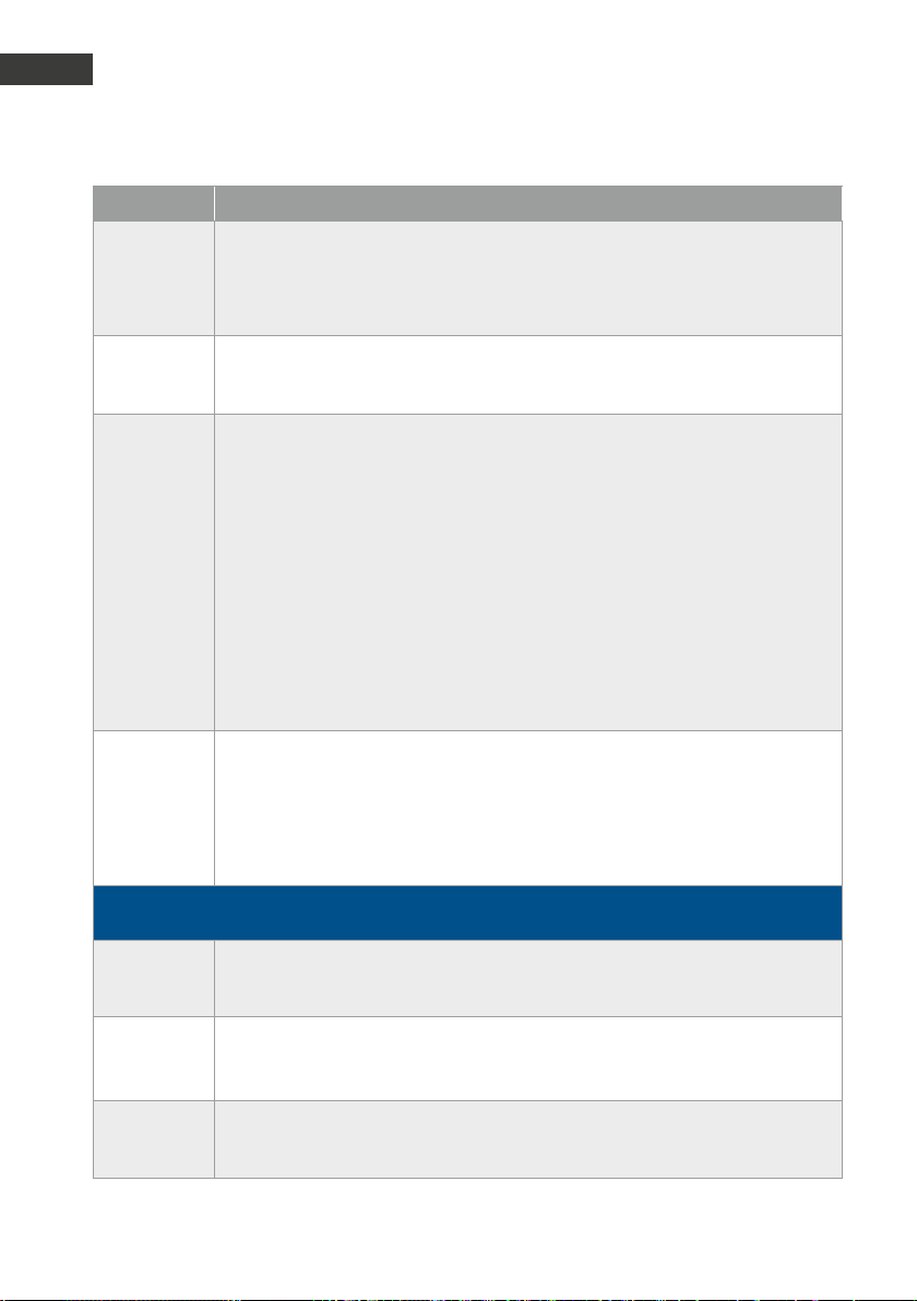
GB
Manual Door intercom devices a / b series 20 / 30 / 40 / 50 / 20-0028A/-0028B
GB
Operation
Entry Function
Switching between operation with and without additional amplifier is only
possible if the additional amplifier is activated via configuration step 07 and an
additional 12V supply is connected.
*8 Disconnecting (only possible for V1.34 or later and if the *# function was
switched to a function other than disconnecting via configuration step 9918)
*8 security
code #
Reset emergency state (only possible for V1.40 or later)
If group calling is active, the device will enter the emergency state if an emergency call was made (deactivation of the misuse protection). When entering *8
and the security code as well as #, the emergency state can be reset. If configuration step 9919 is set to “0”, it is not necessary to enter the security code and
the emergency state can be reset by entering *8#. When entered correctly, the
emergency state reset is confirmed by 2 ok beeps, otherwise there will be an
error beep.
Important: Resetting the emergency state via the *8 function is only possible if
the *# function is set to “disconnecting” via configuration step 9918.
*9 Request alarm input state
1x ok beep ▸ alarm input inactive
2x ok beeps ▸ alarm input active
The alarm input state can be requested in all alarm input operations modes
(configuration step 17) except for operations mode 0 (inactive).
The following commands are only possible for universal devices:
*1 Activate MLM B (roof ) if MLM B is not connected
=MLM for on top of the cabin, the integrated MLM is activated
*2 or *4 Activate MLM A (cabin) if MLM A is not connected
=MLM for inside the cabin, the integrated MLM is activated
*3 or *7 Activate MLM C (pit) if MLM C is not connected
=MLM for underneath the cabin, the integrated MLM is activated
84 www.behnke-online.com
Page 85

Manual Door intercom devices a / b series 20 / 30 / 40 / 50 / 20-0028A/-0028B
Extended operation
6.2. Automatic acoustic setting with ##* function (V1.51 or later)
GB
Using the ##* function, the values for the
acoustic settings (volume, microphone sensibility, transmission signal amplification, receive
signal amplification, echo suppressor damping)
can be determined automatically. Proceed as
follows: Call the door intercom device via a
DMTF-enabled telephone. After the door intercom device has accepted the call, wait at least
5 seconds and then quickly enter the button
sequence ##* security code 0/1/2.
The following modes are possible for the acoustic setting:
0 automatic acoustic setting for an operation
without additional amplifier
1 automatic acoustic setting for an operation
with additional amplifier
2 automatic acoustic setting
(Maintain mode: Operation with additional
amplifier, if it already activates, otherwise
operation without additional amplifier)
When calling the ##* function, make sure to
enter the numbers quickly (=no longer breaks
between the individual characters). When
a wrong security code is entered, the door
intercom device will hang up. If an automatic
acoustic setting is not possible, e.g. because
the additional amplifier is to be used, but there
is no additional 12 V
supply connected, the door intercom device will
emit an error beep after entering the mode.
Important: During the automatic acoustic
setting, there should be no background noise,
if possible, and the telephone used should not
be near the door intercom device and should
not be used in hands-free mode. During the
automatic setting, do not hold the telephone
receiver directly to your ear, because you will
generally hear a loud whistle sound at the end
of the automatic setting (feedback). This is
normal and required to determine the settings. The automatic setting takes approx. 20
seconds. As soon as the automatic setting is
finished, the door intercom device will beep
twice.
85www.behnke-online.com
Page 86
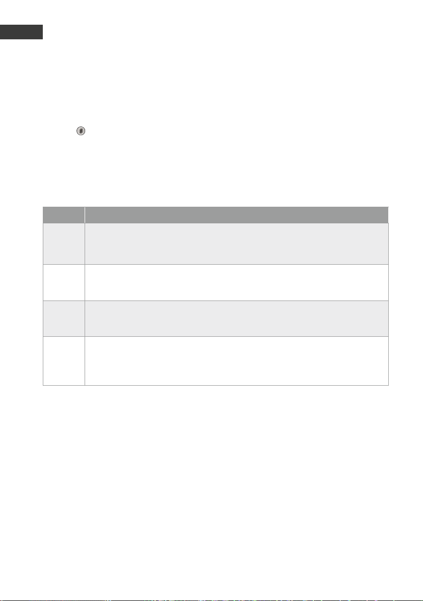
GB
Manual Door intercom devices a / b series 20 / 30 / 40 / 50 / 20-0028A/-0028B
GB
Extended operation
6.3. Call answering when redialling / group calling is active (configuration step 20 active)
Press the button after picking up the handset
to answer the call. Otherwise, the call is automatically disconnected because the redialling / group calling will continue and the next
number will be dialled. Telephone with tone dial
required (cf. configuration step 20 in the exten-
Entry Function
*1 Activate MLM B
(If MLM B is not connected, the integrated MLM is activated)
*2 / *4 Activate MLM A
(If MLM A is not connected, the integrated MLM is activated)
*3 / *7 Activate MLM C
(If MLM C is not connected, the integrated MLM is activated)
*5 Switching between MLM A and the integrated MLM
1x ok beep integrated MLM is activated
2x ok beeps MLM A is activated
sive technical manual – www.behnke-online.
de/handbuch-analog).
The following commands are only possible if
multiple MLMs are connected:
86 www.behnke-online.com
Page 87
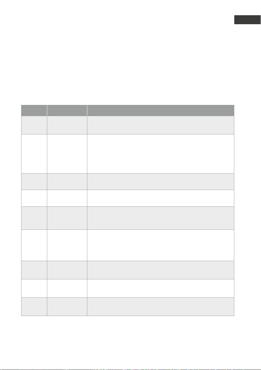
Manual Door intercom devices a / b series 20 / 30 / 40 / 50 / 20-0028A/-0028B
Error table
.
During initialisation, the function of the most important electronics components is verified. If an
error occurs, a sequence of beeps allocated to a particular error will be audible, rather than the
normal high-pitch initialisation beep. You can find the allocations in the following table:
Beeps Error Possible causes
GB
3 EEprom error
4 Key matrix
error
5 Busy tone
decoder error
6 DTMF tone
decoder error
7 1kb-EEprom
from V1.30 or
later
8 Microphone
error
9 Microphone
error
10 Microphone
error
EEprom is not correctly installed in dedicated base
▸
EEprom faulty
▸
connected key, configuration button or number keypad is stuck
▸
or faulty
Connection cable for button or number keypad is damaged
▸
Interference
▸
Moisture on board or in connector
▸
Busy tone decoder is faulty
DTMF tone decode component is faulty
Wrong EEprom, only 2kb EEproms are permitted for V1.30 or later
Compact device: the polarity of the connected microphone is
inverted
Universal device: the polarity of the microphone connected to the
integrated MLM is inverted
the polarity of the microphone connected to the MLM-A of an
universal device is inverted
the polarity of the microphone connected to the MLM-B of an
universal device is inverted
11 Microphone
error
the polarity of the microphone connected to the MLM-C of an
universal device is inverted
87www.behnke-online.com
Page 88

GB
Manual Door intercom devices a / b series 20 / 30 / 40 / 50 / 20-0028A/-0028B
GB
FAQ
.
Door dials no or wrong telephone number
Telephone number from default settings has
▸
not been re-configured
Wrong telephone number configured
▸
Door intercom device has not accepted the
▸
set-up, cf.: Door intercom device cannot be
configured
Remote station in the house rings once, no
▸
voice call *2 (pause for 2 seconds) configure before and after the telephone number
Door intercom device cannot be configured
remotely
The telephone with which you are configuring
▸
the door intercom device does not send any
DTMF tones Use telephone with DTMF tone
Correctly enter the set-up mode with **0000
▸
No (direct) voice call after connection
Check a / b port Port in the telephone
▸
system must be generated as telephone port,
not as TFE/door intercom device/FTZ
Device is constantly initialising during set-up
Check a / b port, deactivate line monitoring if
▸
activated, a / b port must not be disconnected
No busy tone after disconnection, but initialisation of the intercom
Check a / b port, there is no busy tone, but the
▸
telephone system must send a busy tone after
the end of the call. Telephone system must
send a busy tone when ending the call.
Name plate not illuminated
Power supply is missing
▸
Polarity of power supply is reversed
▸
Check connection from name plate to basic
▸
electronics
Door opener is not triggered
Check door opener connection Use closing
▸
contact
Power supply for door opener missing
▸
on-site (not parallel to Behnke power
supply)
Telephone does not send DTMF tones -> cf.:
▸
Door intercom device cannot be configured
Code for opening doors is not or wrongly
▸
configured (default setting 0#)
Confirm code entry with #
▸
Door intercom device without function
Check a / b port, measure if necessary
▸
If additional power supply is connected,
▸
check if it is potential-free
Multiple door intercom devices are connected
▸
in parallel each telephone requires its own
analogue connection and its own potential-free power supply
Coil current of the telephone system is
▸
sufficient
must be more than 20 mA
Cf: Technical Specifications of the door inter-
▸
com device
88 www.behnke-online.com
Page 89

Manual Door intercom devices a / b series 20 / 30 / 40 / 50 / 20-0028A/-0028B
FAQ
GB
Occasional call activation of door intercom
devices
Additional call buttons connected, remove
▸
buttons, do not connect buttons in parallel
Please note the button connection cable
▸
length if the basic electronics is detached.
Please refer to the corresponding basic electronic details.
External button connected, check button for
▸
functionality, bounce, freedom from potentials, no common mass.
Security code if the door intercom device is
unknown
Hardware reset required
▸
1. Remove telephone line (a / b)
2. If applicable, remove additional 12V to 15V
power supply
3. Remove EEprom (component on the top
right of the board with four legs both on
the left and the right side, s. Kapitel „3.1.
Anschlusspläne“ ab Seite 60)
4. Insert telephone line and wait until the electronics has beeped 3 times
5. Re-insert EEprom (under connected a / b
line)
6. Press the * key to reset and hold until
the electronics boots with a beep sound.
Release button.
Press the # key to fully reset the device and
hold until the electronics boots with a long
beep sound.
Delete configuration value (e.g. telephone
number)
Start set-up mode
▸
Enter configuration step and confirm with #
▸
The set configuration value will be deleted.
89www.behnke-online.com
Page 90

GB
Manual Door intercom devices a / b series 20 / 30 / 40 / 50 / 20-0028A/-0028B
GB
Technical Specifications
.
Connection type: analogue telephone line, a / b port
Power supply: via the a / b port
Coil tension: 20-70 VDC
Coil current: 20-60 mA
Additional power supply: 12-15 V= potential-free
Behnke power supply unit or any other additional power supply
in connection with a Behnke DC-DC converter; one Behnke door
intercom device per power supply unit
Terminal: ZR according to TBR 21
Recognised caller signal: cannot be specified exactly, as it depends on the signal’s
amplitude, frequency and interval
Recognised busy signal: 400-450 Hz sinus
Recognised busy signal interval: Signal tones for 160-700 ms or pauses for 160-700 ms respectively
Permitted cable length: max. 10 m each (for MLM A, +MLM B, +MLM C, LS, MIC, T1,andT2)
or max. 25 m each (for LS, MIC, T1,andT2, if no other MLM is connected)
Dialling methods: DTMF dialling, 50/50 ms (tone/pause)
Built-in relays: 2 pcs. (2 switch relays)
Relay switch power: max. 60 VA/24 W: 0,5A, 120V~ or 1A, 24V =(resistive load)
Additional power supplies
on MLMs: max. current draw 30 mA per MLM
Memory: EEprom, non-volatile
IP protection class: 54
Operating temperature: -20 °C to +50 °C
Tested according to: TBR 21 as well as EC 201 121 (EU-wide network access) EN 55022,
EN55024 (Electromagnetic
Compatibility)
EN60950 (Product Safety)
90 www.behnke-online.com
Page 91

Manual Door intercom devices a / b series 20 / 30 / 40 / 50 / 20-0028A/-0028B
.
Legal Information
GB
1. We reserve the right to change our products,
without notice, for technical progress. As a
result of continuous development, the products
illustrated may look different from the products
actually delivered.
2. Reprints of texts, images or pictures or copies
from these instructions in any media – given in
full or as extracts – require our express written
consent.
3. Design and layout of these instructions are
copyright protected. We do not assume any
liability for possible errors, contents errors and
misprints (including technical data or within
images and and technical diagrams).
Information with regard to product liability:
1. All products mentioned in these instructions
may only be used for the purpose intended. In
case of doubts, please contact a competent
specialist or our services department (cf. telephone numbers).
2. Products with a power supply (especially
those plugged in to 230V) must be unplugged
before opening or during installation.
3. Damage and consequential damage resulting
from altering or meddling with our products or
their improper use are excluded from product
liability. This also applies to improper storage or
external influences.
4. The respective guidelines for working on power supplies with 230V or batteries equally apply
to working with our products, e.g. directives
regarding electromagnetic compatibility or the
Low Voltage Directive. Please leave corresponding work to trained specialists familiar with the
matter.
Electromagnetic
Compatibility
Low Voltage Directive
5. Our products meet all technical guidelines
and telecommunications regulations currently
applicable in Germany and the EU.
91www.behnke-online.com
Page 92

GB
Manual Door intercom devices a / b series 20 / 30 / 40 / 50 / 20-0028A/-0028B
GB
Technical Specifications
Notes
92 www.behnke-online.com
Page 93

Version 2.3
D Türstationen a / b Serie 20 / 30 / 40 / 50 / 20-0028A/-0028B Seite ...... 3
GB Manual Door Intercom Devices a / b series 20 / 30 / 40/ 50 /
20-0028A/-0028B Page ..... 49
FR Portiers téléphoniques a/b Séries 20 / 30 /40 / 50 /
20-0028A/-0028B Page ..... 95
Page 94
Notice adaptateur réseau sécurisé / adaptateur portier sécurisé
F Contact
Remarques importantes
Veuillez vous assurer que les dispositifs et accessoires Behnke ne sont installés et entretenus que
par des électriciens, informaticiens et techniciens réseau agréés et respectant les normes et régulations en vigueur. Avant d'effectuer des travaux d'entretien ou de réparation, toujours débrancher
les appareils des réseaux électrique (bloc d'alimentation), informatique et téléphonique et respecter les règles de sécurité en vigueur.
Vous trouverez des informations légales complémentaires sur la page 137.
Infoligne
Pour des informations détaillées
concernant nos produits, nos projets et
nos services: +49 (0) 68 41/81 77-700
Hotline SAV 24h/24h
Vous avez besoin d'aide? Nous sommes
à votre service 24h/24 et vous proposons
des conseils et solutions pour toutes vos
questions d'ordre technique, ainsi qu'une
aide à la mise en service:
+49 (0) 68 41/81 77-777
Telecom Behnke GmbH
Gewerbepark „An der Autobahn“
Robert-Jungk-Straße 3
66459 Kirkel
e-mail et adresse internet
www.behnke-online.de
[email protected]
94 www.behnke-online.fr
Page 95

Notice adaptateur réseau sécurisé / adaptateur portier sécurisé
Sommaire
1. Introduction 87
1.1. Généralités .......................................................................................................................87
2. Montage 89
2.1. Série 20 / 30 / 40 / 50 (20-0001/-0002/-0010/-0013/-0014/-0016/-0041/-0043) .................89
2.2. Montage mécanique séries 20/30 .................................................................................... 91
2.3. Placez l’étiquette avec l’inscription ..................................................................................94
2.4. Appareils universels 20-0005/-0006/-0018/-0026/-0028A/-0028B/-0048 ......................95
2.5. Notice série 50 .................................................................................................................95
3. Raccordement 96
Séries 20 / 30 / 40 / 50 et 20-0005/-0006/-0018/-0026/-0028A/-0028B/-0048 .............. 96
▸
3.1. Répartition des connexions ..............................................................................................97
Électronique compacte 20-0001/-0002/-0010*/-0013/-0014/-0014/-0016/-0041/-0043 ...97
▸
Électronique universelle 20-0005 .................................................................................. 98
▸
Électronique universelle 20-0006/-0018/-0026 (jusqu’au 4ème trimestre 2018) ............. 99
▸
Électronique universelle 20-0006/-0018/-0026 (à partir du 1er trimestre 2019) ..............100
▸
Électronique universelle 20-0048 (à partir du 4ème trimestre 2018) ................................101
▸
Électronique universelle 20-0048 (à partir du 1er trimestre 2019) ................................... 102
▸
Poste d'appel d'urgence ascenseur 20-0028A
▸
(jusqu'au firmware BT MA 1.63, livré jusqu'au 3ème trimestre 2018) .................................. 103
Poste d'appel d'urgence ascenseur 20-0028A
▸
(jusqu'au firmware BT MA 1.63, livré jusqu'au 2ème trimestre 2019) .................................. 105
Poste d'appel d'urgence ascenseur 20-0028B
▸
(à partir de la version BT MA 1.64 du firmware, à partir du 2ème trimestre 2019) ................ 107
F
4. Configuration 109
5. Utilisation 119
6. Fonctionnement détaillé 120
6.1. Commandes disponibles durant la communication .......................................................... 120
6.2. Réglage acoustique automatique avec fonction ##** (à partir de V1.51)........................... 120
6.3. Prise d'appel avec rappel automatique du numéro / appel groupé activé
(menu configuration 20 active) .............................................................................................. 123
7. Tableau des erreurs 124
8. Foire aux questions 125
9. Caractéristiques techniques 127
10. Informations légales 128
95www.behnke-online.fr
Page 96

Notice adaptateur réseau sécurisé / adaptateur portier sécurisé
F
Introduction
.
INTRODUCTION
1.1. Généralités
Lors de l’installation et de la configuration de
votre portier téléphonique, veuillez respecter
les propriétés suivantes:
Fonctionnement sur un poste annexe analo-
▸
gique d'une installation téléphonique, d'une
connexion principale analogique ou d'autres
ports a / b. Remarque : lors de l'utilisation
d'autres ports a / b, veuillez vous assurer que
ces derniers sont conformes aux spécifications correspondantes du poste analogique,
telles que tonalité d'occupation, transparence
multifréquences, etc.
Fonctionnement sans alimentation électrique
▸
supplémentaire possible
Les portiers fonctionnent en mode full duplex,
▸
commutable en semi-duplex et simplex
(une alimentation supplémentaire peut être
nécessaire).
Conditions de montage
La hauteur de montage optimale est atteinte,
▸
lorsque la distance d’utilisation du portier
téléphonique est de 30-50cm et qu’une personne se tenant debout peut confortablement
parler dans le microphone.
Essayez d’assurer une distance maximale
▸
entre le microphone et le haut-parleur. De
cette manière, la communication en fullduplex sera aussi claire que possible.
Pour les modules à montage arrière (=mon-
▸
tage derrière une paroi frontale existante),
assurez-vous que les fentes d’entrée et de
sortie du son au niveau du microphone et du
haut-parleur sont suffisamment grosses (ou
moins 75% de la surface de la membrane
du haut-parleur pour la sortie du son et 75%
pour l’ouverture d’entrée du son au niveau
du microphone). Voir les plans à l’échelle
disponibles à l'adresse www.behnke-online.
de/downloads
Pour des raisons acoustiques, montez tou-
▸
jours le module à montage arrière de manière
à ce qu’il soit affleurant (sans espace) à la
paroi frontale et utilisez absolument les joints
fournis entre la paroi frontale et le module
intégré.
Montage en extérieur
Les portiers des séries 20 et 30 doivent être
▸
équipés d'un châssis anti-pluie lorsqu'ils sont
encastrés ou lorsqu’un boîtier apparent est
utilisé lors d’un montage en saillie (veillez
toujours à ce que le joint fourni soit correctement installé).
Dans le cas d’un montage encastré, assu-
▸
rez-vous que l’arête supérieure du portier
téléphonique est bien étanche contre la
saleté et la pluie, en particulier lorsque le
support est irrégulier (utilisez par ex. du silicone). Laissez le milieu de l’arête inférieure
du portier téléphonique ouverte afin de
laisser l’eau s’écouler. Lors de l’utilisation
de caches, le cache doit être pressé contre le
boîtier encastrable ou contre la surface lors
d’un montage cloison creuse, et étanchéifié
avec un mastic adapté.
Lors d’un montage sur des colonnes autres
▸
que celles de Behnke, veuillez prendre les
mesures nécessaires afin de vous assurer
qu’il n’y aura pas de condensation dans la
colonne.
96 www.behnke-online.fr
Page 97

Notice adaptateur réseau sécurisé / adaptateur portier sécurisé
Joints d’étanchéité
Pour protéger de l’humidité, assurez-vous
que les joints d’étanchéité fournis sont bien
positionnés lors du montage du portier téléphonique. Le joint doit reposer proprement sur le
cadre du boîtier encastré ou en saillie ! Les boîtiers encastrables sont conçus pour un montage
dans un mur ou dans des plaques de plâtre.
Les consignes de montage les plus importantes
sont collées à l’intérieur des boîtiers.
Pour un montage dans des plaques de plâtre,
veuillez également commander le kit de montage (réf. 20-5216).
Retirer l’électronique des touches,
haut-parleur et microphone (attention: uniquement possible avec les électroniques suivantes)
20-0005: max. 25 m
▸
20-0006/-0018/-0026/-0026/-0028A/-00
▸
28B et 20-0048 : Avec un bouton max. 25 m,
avec deux boutons 12,5 m, avec trois boutons
8,5 m*
*Pour des longueurs de câble supérieures
aux longueurs mentionnées ci-dessus, il est
possible d’utiliser une électronique de base
40-0006 (Triphonie).
Câblage pour montages à distance
(20-0005/-0006/-0006/-0018/-0026/)
-0028A/-0028B/-0048)
Pour le montage, utilisez des câbles patch
▸
Behnke ou des câbles blindés, par ex. IY-ST-Y
ou AY-ST-Y, et raccordez le blindage du câble
à la borne 12 V- du portier téléphonique (pas
à la terre).
Remarque: placez le blindage du câble
aussi près que possible du haut-parleur, du
microphone et de la touche dans la zone du
panneau avant et isolez-le à cet endroit.
Introduction
Entretien et nettoyage
Vous avez installé des produits Behnke de
haute qualité avec des plaques avant fabriquées à partir de différents matériaux. Pour
tous les matériaux, il est nécessaire de procéder
à un nettoyage régulier, à intervalles suffisamment courts, en utilisant un produit nettoyant
adapté au matériaux.
Ainsi, vous éviterez un vieillissement précoce
des surfaces et une formation de patine sur
celles-ci.
Pièces originales Behnke
N’utilisez que des accessoires ou pièces de
rechange Behnke, ceci vaut également pour
les blocs d’alimentation! Seulement dans ce
cas pouvons-nous garantir un fonctionnement
sans entrave. Ne montez et n’installez les
composants électroniques que dans les boîtiers
fournis. Lors du montage dans des boîtiers
autres que ceux fournis, le fonctionnement et
l’homologation ne sont plus garantis.
Configuration
Les portiers téléphoniques peuvent être configurées localement sur l'électronique de base ou
à distance par téléphone (signal DTMF). Toutes
les stations de porte sont livrées préconfigurées
avec une configuration standard.
Réglementation en vigueur
Respectez les prescriptions en vigueur pour
l'installation d'appareils de télécommunication
et d'assemblages électriques !
F
97www.behnke-online.fr
Page 98

Notice adaptateur réseau sécurisé / adaptateur portier sécurisé
F
Montage
.
MONTAGE
Remarque: Vous trouverez les cotations et les schémas de montage à l’adresse
www.behnke-online.de/bemassung
2.1. Série 20 / 30 / 40 / 50 (20-0001/-0002/-0010/-0013/- 0014/-0016/- 0041/- 0043)
Remarque: pour des raisons d'optique et de
protection contre l'humidité veillez au sens
du brossage de l'aluminium lors de la mise en
place des modules, attention au détrompeur
d'orientation! Le portier téléphonique ne doit
être monté qu’avec un cadre adapté. Évitez
la formation de condensation à l’intérieur de
l’appareil! Montez le portier téléphonique de
manière à ce que de l’eau ne puisse pas rester
sur la plaque avant. Lors du montage dans des
colonnes d’autres fabricants, faites particulièrement attention à la ventilation et à la circulation
d’air dans la colonne.
En cas de montage délocalisé courte distance
de l'électronique, le boîtier de l’électronique est
remplacé par une contre-plaque ouverte correspondant au cadre avant (utilisez la rallonge de
touche 20-9305, ne rallongez pas les raccords
vous-même, max. 3m).
Relier les câbles dans l'ordre suivant :
1. Raccordez les touches (RT) ▸ aux connecteurs
MQS de T1 à T8 marqués par la bague jaune.
T1 (touche 1) = menu configuration 21
...
T8 (touche 8) = menu configuration 28
Lors du raccordement de claviers d’un autre
fabricant, faites attention à ce que les claviers
soient bien homologués. Les «tableaux de
sonnettes» ne le sont généralement pas.
(cf. page 103 ) Les claviers doivent avoir un
potentiel isolé.
2. Haut-parleur (LS) ▸ au connecteur marqué
par la bague bleue
3. Enfichez le microphone (Mic) ▸ à brancher au
connecteur marqué d’une bague blanche
4. Clavier numérique ▸ au connecteur blanc à
12 broches
5. Caméra ▸ Prise noire à 4 pôles (signal vidéo
PAL)
6. Au besoin, connectez la gâche au relais 1.
(Relais = contact hors tension: ne fait commuter que le circuit électrique de la gâche,
ne l’alimente pas en courant électrique. Pour
cela, utilisez le contact de fermeture). La
gâche nécessite un circuit électrique propre.
Le relais 2 sert à activer des fonctions de
commutation supplémentaires.
98 www.behnke-online.fr
Page 99

Notice adaptateur réseau sécurisé / adaptateur portier sécurisé
7. Si nécessaire, raccordez 12-15 V=(sans poten-
tiel; utilisez le bloc d'alimentation enfichable
Behnke 20-9585). Nécessaire pour l'éclairage,
le chauffage intégré et l'amplificateur d'ap-
point ; pas nécessaire pour le fonctionnement
téléphonique, y compris toutes les fonctions.
Des fonctions spéciales telles que l'appa-
reil photo, l'écran, les annonces vocales, le
contrôle de l'heure peuvent nécessiter une
électronique supplémentaire ainsi qu'une
alimentation électrique supplémentaire. S'il y
a plusieurs portiers téléphoniques, assu-
rez-vous toujours d'une isolation galvanique
de l'alimentation supplémentaire. Remarque:
ne pas faire fonctionner plusieurs appareils
en parallèle avec un bloc d'alimentation sans
convertisseur DC/DC.
8. Raccordez la ligne téléphonique : a / b à
partir d'un poste analogique d'un système
téléphonique, d'une ligne principale analo-
gique ou d'autres interfaces a / b. Après le
raccordement de la ligne téléphonique, vous
entendez un long bip sonore qui signale que
le portier téléphonique est prêt à fonctionner
(=initialisation). Le portier téléphonique est
maintenant prêt à être configuré. Remarque:
les appareils ne doivent pas être utilisés en
parallèle sur un câble a/b.
Montage
F
Poser les câbles non utilisés dans le boîtier
des modules avec l'extrémité ouverte (connecteur) vers le bas. Cela empêche l'infiltration de
l'humidité dans le connecteur. Posez ensuite
le boîtier de l'électronique sur le boîtier des
modules.
99www.behnke-online.fr
Page 100
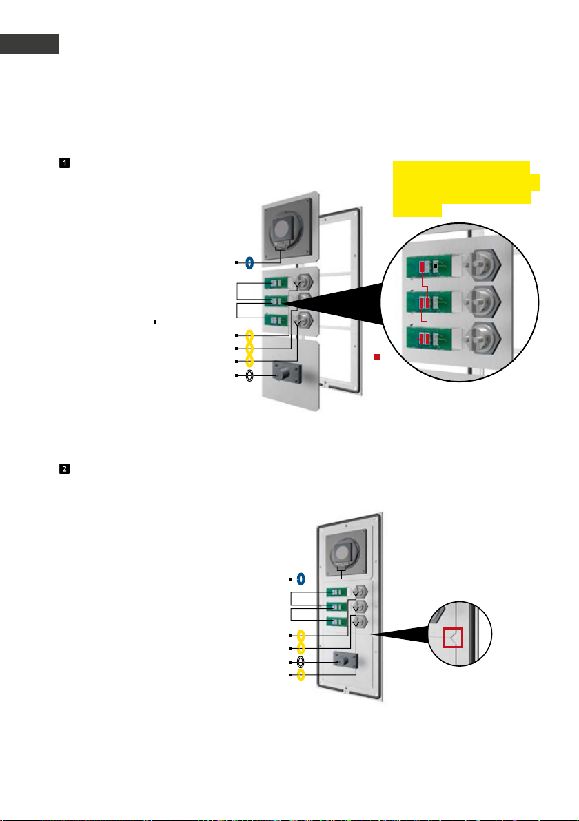
Notice adaptateur réseau sécurisé / adaptateur portier sécurisé
F
Montage
2.2. Montage mécanique séries 20/30
Insérer les modules fonctionnels dans le cadre avant
HP
Ponts
Éclairage 12 V=
(ligne provenant de
l’électronique de base)
Encastrez les modules par l’arrière dans le cadre.
RT
RT
RT
Mic
T
T
T
Raccordement de l’éclairage
des touches du clavier Behnke
(touches éclairées possibles
en option)
Éclairage
12 V=
Ponts 12 V pour l’éclairage
des champs d’inscription
Modules fonctionnels dans le cadre avant
HP
RT
T
RT
T
Mic
RT
T
Lors de l'insertion des modules, veillez impérativement au détrompeur d'orientation. Veillez aussi à
ce que les modules émettent un « clic » audible lorsqu'ils sont insérés.
100 www.behnke-online.fr
 Loading...