

Page 1
Grid and System
Protection
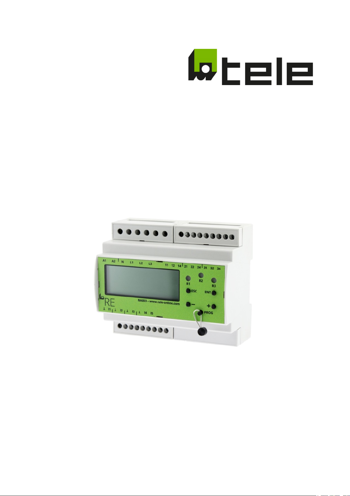
RE - NA003
Part no.: 2700000I
USERS GUIDE
for SW: 01.05.01i
Subject to modifications and errors Page 1 of 71 2019-06-26 edition
Page 2

Table of content
Safety ...................................................................................................................................................................... 5
1
1.1 Intended use ................................................................................................................................................. 5
1.2 Safety advice ................................................................................................................................................. 5
1.3 Qualified electrician ..................................................................................................................................... 6
2 Installation and connection ................................................................................................................................. 6
2.1 Dimensions and operating elements ........................................................................................................ 6
2.2 Back-up fuse of the supply voltage ............................................................................................................ 6
2.3 Terminal allocation ...................................................................................................................................... 7
2.4 Installation on top-hat rail according to EN 60715 .................................................................................. 7
2.5 Circuit diagram 1 .......................................................................................................................................... 8
2.6 Circuit diagram 2 (CEI 0-21) ......................................................................................................................... 9
3 Function ................................................................................................................................................................10
3.1 Features ......................................................................................................................................................10
3.2 Functional description ...............................................................................................................................10
3.2.1 Innovations with regard to VDE-AR-N 4105........................................................................................11
3.3 Overview of the implemented configurations ........................................................................................12
3.3.1 CEI 0-21 ...................................................................................................................................................12
3.3.2 VDE 0126.................................................................................................................................................12
3.3.3 VDE-AR-N 4105 (Pn ≤ 50 kW) ................................................................................................................12
3.3.4 VDE-AR-N 4105 (Pn > 50 kW) ................................................................................................................12
3.3.5 VDE-AR-N 4105 (inverter) ......................................................................................................................13
3.3.6 VDE-AR-N 4110 (tested according to TR3, evaluation report TR8) ...................................................13
3.3.7 G99/1/3 LV (low voltage) .......................................................................................................................13
3.3.8 G99/1/3 HV (medium/high voltage) .....................................................................................................13
3.3.9 G98/1/2 ...................................................................................................................................................13
3.3.10 C10-11 LV (low voltage) .........................................................................................................................14
3.3.11 C10-11 MV (medium voltage) ...............................................................................................................14
3.3.12 E 8001/8101............................................................................................................................................14
3.3.13 EN 50438.................................................................................................................................................14
3.3.14 EN50438 (DK) .........................................................................................................................................14
3.3.15 NRS 097-2-1: 2017 .................................................................................................................................15
3.3.16 OPEN SETUP ...........................................................................................................................................15
3.4 Comparators ...............................................................................................................................................15
3.4.1 Voltage monitoring ................................................................................................................................16
3.4.2 Frequency monitoring ..........................................................................................................................16
3.4.3 Phase shift monitoring ..........................................................................................................................17
3.5 Configuration ..............................................................................................................................................17
3.6 Other Parameter ........................................................................................................................................18
3.6.1 Feedback contact ...................................................................................................................................18
Subject to modifications and errors Page 2 of 71 2019-06-26 edition
Page 3

3.6.2 Turn-on delay .........................................................................................................................................19
3.6.3 Random turn-on delay ..........................................................................................................................19
3.6.4 Connection Mode ..................................................................................................................................20
3.6.5 Nominal Voltage ....................................................................................................................................21
3.6.6 Functional Safety ...................................................................................................................................21
3.6.7 Operational Mode .................................................................................................................................22
3.7 Settings of the implemented configurations ..........................................................................................23
3.7.1 CEI 0-21 ...................................................................................................................................................24
3.7.2 VDE 0126.................................................................................................................................................27
3.7.3 VDE-AR-N 4105 (Pn ≤ 50kW) .................................................................................................................29
3.7.4 VDE-AR-N 4105 (Pn > 50kW) .................................................................................................................31
3.7.5 VDE-AR-N 4105 (Converter) ..................................................................................................................33
3.7.6 VDE-AR-N 4110 (tested according to TR3, evaluation report TR8) ...................................................35
3.7.7 G99/1/3 LV (low voltage) .......................................................................................................................37
3.7.8 G99/1/3 HV (medium/high voltage) .....................................................................................................39
3.7.9 G98/1/2 ...................................................................................................................................................41
3.7.10 C10-11 LV (low voltage) .........................................................................................................................43
3.7.11 C10-11 MV (medium voltage) ...............................................................................................................45
3.7.12 E 8001/8101............................................................................................................................................47
3.7.13 EN 50438.................................................................................................................................................50
3.7.14 EN50438 (DK) .........................................................................................................................................52
3.7.15 NRS097-2-1 2017 ...................................................................................................................................54
3.7.16 OPEN SETUP ...........................................................................................................................................57
3.8 Loss Of Mains detection ............................................................................................................................61
3.8.1 Loss Of Mains detection via voltage measurement ..........................................................................61
3.8.2 Loss Of Mains detection via RoCoF .....................................................................................................61
3.8.3 Loss Of Mains detection via vector shift .............................................................................................61
3.9 Test function ...............................................................................................................................................61
3.10 Digital inputs ...............................................................................................................................................61
3.11 Output contacts ..........................................................................................................................................61
3.12 Error .............................................................................................................................................................61
3.12.1 Measurement error ...............................................................................................................................62
3.12.2 System error...........................................................................................................................................62
3.12.3 Error memory (LOG) ..............................................................................................................................62
4 Technical data ......................................................................................................................................................63
4.1 Supply circuit ..............................................................................................................................................63
4.2 Measuring circuit ........................................................................................................................................63
4.3 Measuring ranges ......................................................................................................................................63
4.4 Digital inputs ...............................................................................................................................................63
4.5 Output circuit ..............................................................................................................................................64
4.6 Accuracy ......................................................................................................................................................64
Subject to modifications and errors Page 3 of 71 2019-06-26 edition
Page 4

4.7 Insulation data ............................................................................................................................................64
4.8 Environmental conditions .........................................................................................................................64
4.9 Electrical connection ..................................................................................................................................65
4.10 Sealing wire .................................................................................................................................................65
4.11 Protection class ..........................................................................................................................................65
5 Operation and commissioning ..........................................................................................................................66
5.1 Initial commissioning .................................................................................................................................66
5.2 Menu navigation ........................................................................................................................................66
5.2.1 Level 0 .....................................................................................................................................................66
5.2.2 Level 1 .....................................................................................................................................................66
5.2.3 Level 2 .....................................................................................................................................................67
5.2.4 Level 3 .....................................................................................................................................................67
5.2.5 Level 4 .....................................................................................................................................................67
5.2.6 Level 5 .....................................................................................................................................................67
5.3 Menu structure ...........................................................................................................................................69
5.4 Applicable rules and standards ................................................................................................................70
5.5 Lead seal .....................................................................................................................................................71
Subject to modifications and errors Page 4 of 71 2019-06-26 edition
Page 5

1 Safety
Caution! Never work when voltage is applied.
This poses a life-threatening risk! Never use the device if there is obvious
damage! Use only by trained specialist personnel!
1.1 Intended use
The TELE NA003 serves as grid and system protection for supplying cogeneration units, wind power stations,
hydroelectric power plants, and photovoltaic systems.
In the event of a power failure or a fault in the grid of the energy supply company, private small power
plants must immediately be isolated from the public grid to prevent accidental infeed. For one, maintenance
personnel could be endangered without immediate grid separation, and secondly, consumers could be
exposed to impermissible voltages and frequencies.
In case the grid operator requires threshold values that deviate from the standards, it is possible in part to
set some of the threshold values outside of the standard defined range.
Outside of this range the device is no longer in compliance with standards and the corresponding
certificates lose their validity. This status is shown on the display by the identifier "ncnf." Settings outside of
this range are therefore within the operator's scope of responsibility and/or the acceptance authority of the
system.
1.2 Safety advice
This device was built and tested in accordance with recognized technical safety regulations. However,
incorrect use can still result in danger for both persons and machine.
Only use this device as intended, in a technical safe condition, and in compliance with the applicable rules
and regulations for accident prevention valid at the usage location.
• Fix all faults that could impair the safety immediately.
• Do not make any unauthorized changes and only use spare parts and additional devices that are
sold or expressly recommended by the manufacturer of the device.
• The device may no longer be used in case of obvious damage.
• Country-specific standards and guidelines are to be observed.
• The NA003 can be protected against authorized changes after commissioning via password
protection or sealing. One of the protection mechanisms named above must be applied if this is
required in the respective country-specific standard or guidelines.
Subject to modifications and errors Page 5 of 71 2019-06-26 edition
Page 6
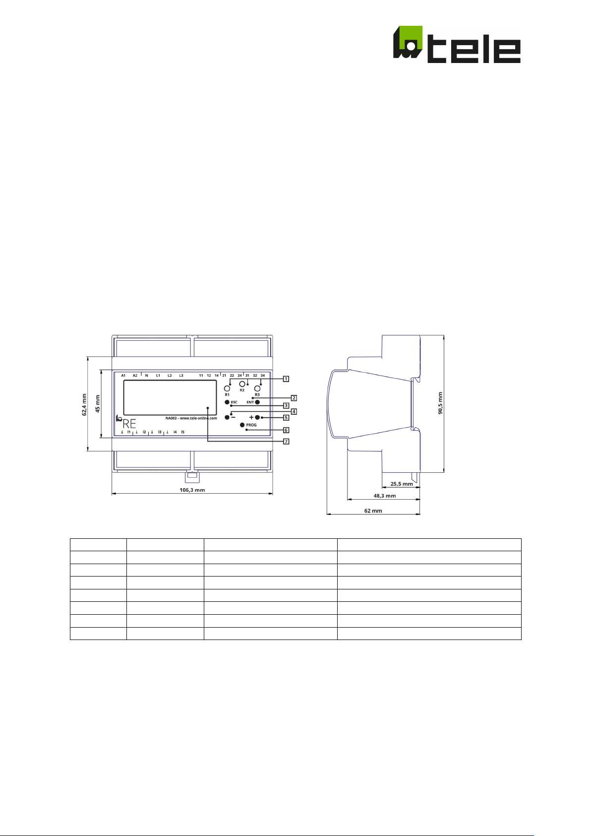
Legend
Labeling
Type
Function
1
R1, R2, R3
LED (yellow)
Output relay status display
2
ENT
Button
ENTER, input confirmation, next level
3
ESC
Button
ESCAPE, input rejection, back a level, Test
4 - Button
Parameter setting, display change
5 + Button
Parameter setting, display change
6
PROG
Button (can be sealed)
PROGRAM, programming
7 LCD-display 4x20 characters
Display
1.3 Qualified electrician
A qualified electrician can independently recognize and prevent dangers from electricity. Requirements for
this are:
• Knowledge of electrical engineering
• Experience in electrical work
• Knowledge and work experience with the corresponding system or similar systems (system type)
• Knowledge of the hazards and countermeasures
• The ability to recognize whether safety is provided during the performance of work
Qualified electricians are specially trained and know the relevant standards and regulations for the work
environment in which they are active. The regulations of the corresponding country apply.
2 Installation and connection
2.1 Dimensions and operating elements
2.2 Back-up fuse of the supply voltage
The supply and measuring voltages of all system components are to be secured with back-up fuses. The
back-up fuses are to be dimensioned according to the conductor cross-section used.
We recommend securing the output relay against the danger of short-circuit with a 5A fast acting fuse!
Subject to modifications and errors Page 6 of 71 2019-06-26 edition
Page 7
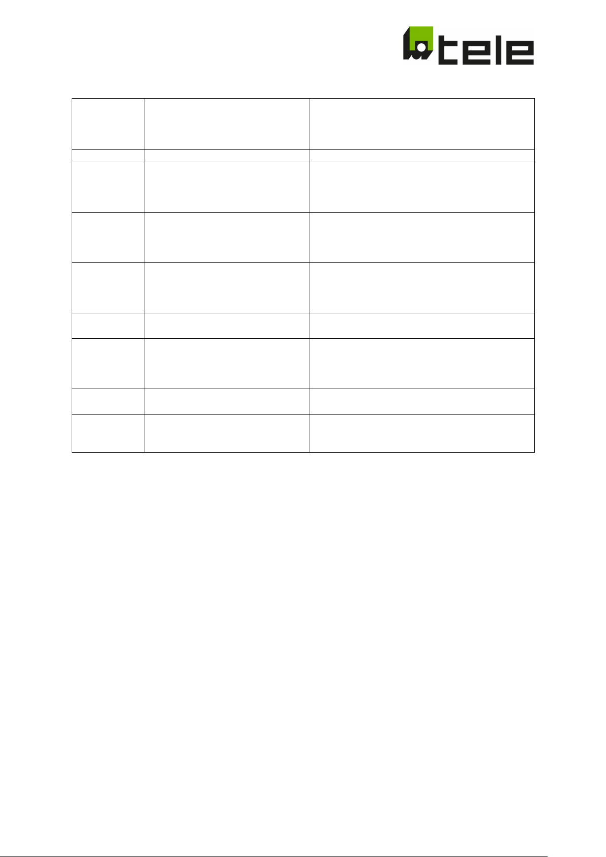
A1, A2
Supply circuit
DC: 24V
A2: N (-)
11, 12, 14
Output relay channel A (changeover
R1
Isolated
14: normally closed
21, 22, 24
Output relay channel B (changeover
Isolated
31, 32, 34
Output relay channel D (changeover
R3
Isolated
34: normally closed
I1, ┴
Digital input 1
(feedback contact of contactor A)
Isolated (24V/5mA)
Input active: I1 and ┴ connected
I2, ┴
Digital input 2
Isolated (24V/5mA)
I3, ┴
Digital input 3
(remote shutdown)
Isolated (24V/5mA)
Input active: I3 and ┴ connected
I4, I5, ┴
Digital input 4 and 5
For CEI 0-21
Input active: I4 resp. I5 and ┴ connected
2.3 Terminal allocation
AC: 110 - 230V
A1: L (+)
L1, L2, L3, N Measuring circuit UN: 3x400V AC
contact)
Status display through yellow LED
contact)
Status display through yellow LED
R2
contact)
Status display through yellow LED
(feedback contact of contactor B)
11: Root
12: normally opened
21: Root
22: normally opened
24: normally closed
31: Root
32: normally opened
Input active: I2 and ┴ connected
Not applicable for all country-specific standards in
which no functional safety is required!
(parameter switchover)
Isolated (24V/5mA)
2.4 Installation on top-hat rail according to EN 60715
Latch the mounting clip on the reverse of the device to the top-hat rail so that a safe and secure fit is
ensured.
Subject to modifications and errors Page 7 of 71 2019-06-26 edition
Page 8
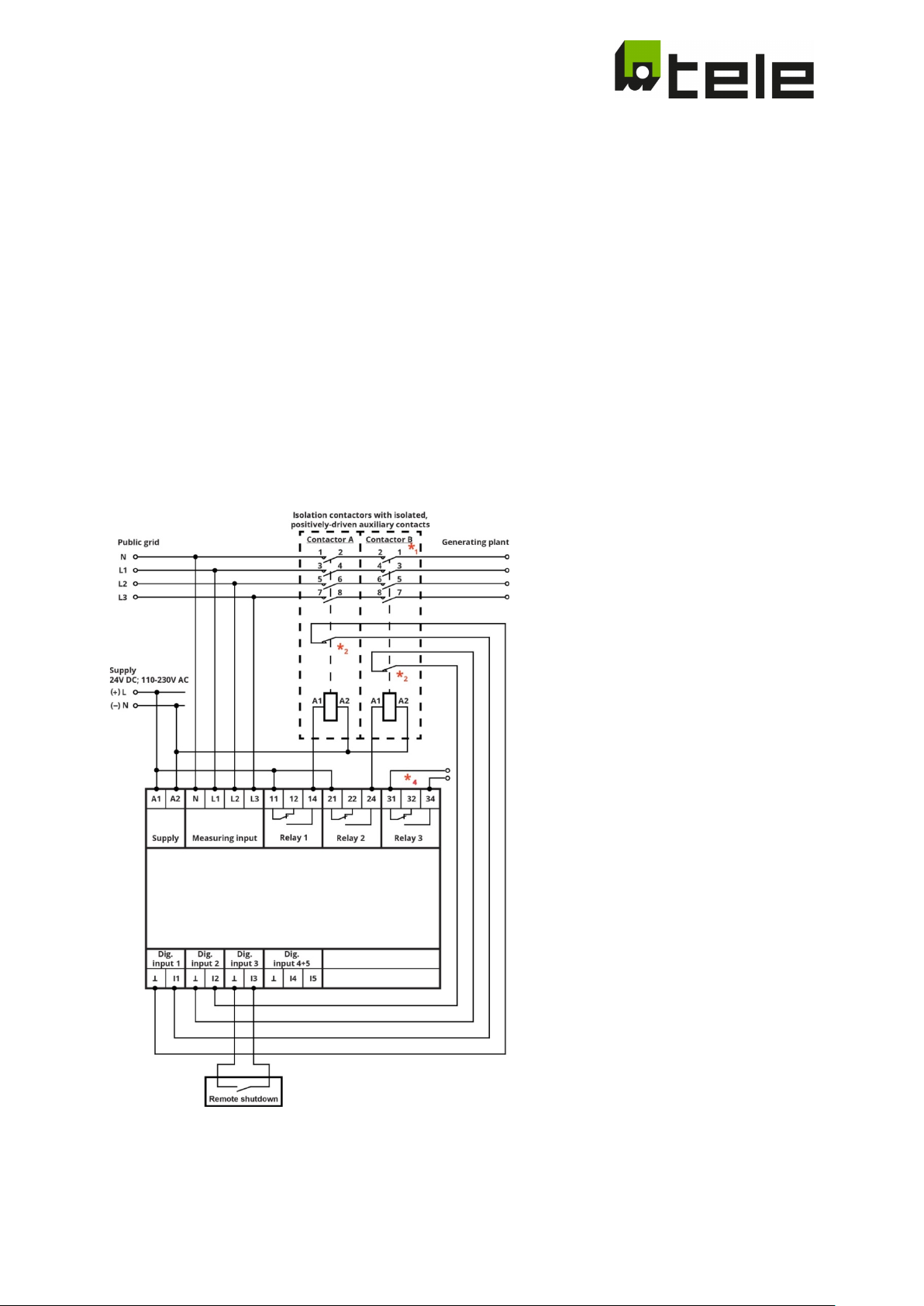
2.5 Circuit diagram 1
VDE V 0126-1-1
ÖNorm E 8001-4-712 / E 8101-4-712
EN50438
NRS 097-2-1:2017
VDE-AR-N 4105:2018-11 (Pn ≤ 50 kW) *
VDE-AR-N 4105:2018-11 (Pn > 50 kW) *
VDE-AR-N 4105:2018-11 (Inverter) *
VDE-AR-N 4110:2018-11 *1
G99-1-3 LV *1
G99-1-3 HV *
G98-1-2 *1
C10-11 LV *1
C10-11 MV *1
EN50438 (DK) *3
OPEN SETUP *
1, *4
1, *4
4
1
3
*1 … Contactor B not applicable for all country-specific standards in which no functional safety is required!
*
… Auxiliary contact as normally opened, normally closed, or can be configured "not monitored”.
2
*
… 1- or 2-channel connection possible and can be configured.
3
*
… Evaluation, contact error for autogeneration plants only for VDE-AR-N 4105:2018-11
4
Subject to modifications and errors Page 8 of 71 2019-06-26 edition
Page 9
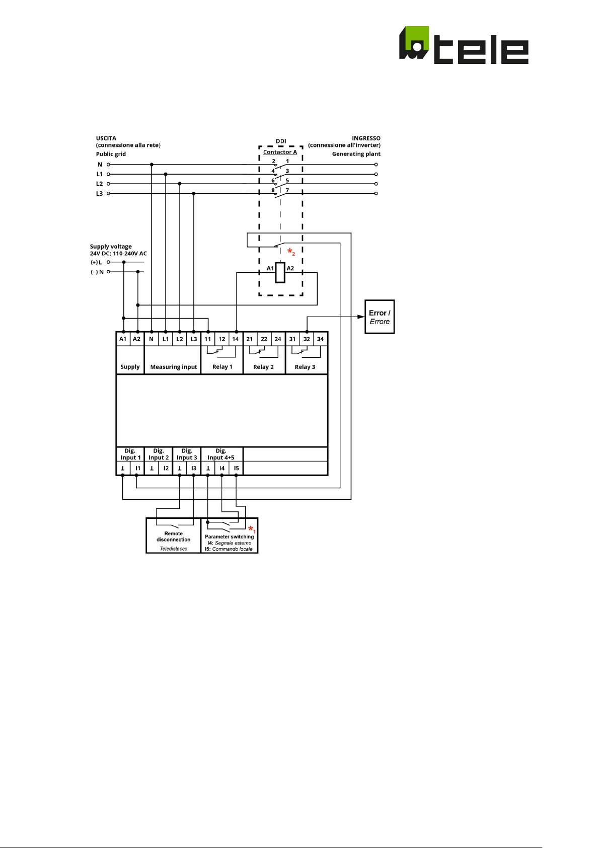
2.6 Circuit diagram 2 (CEI 0-21)
CEI 0-21
*1 Parameter switching:
definitive mode (Operational mode 0):
I4 inactiv / contact open: overfrequency 1, underfrequency 1
I4 activ / contact closed: overfrequency 2, underfrequency 2
transitory mode (Operational mode 1):
I5 active / contact closed: overfrequency 2, underfrequency 2
I5 inactive / contact open: overfrequency 3, underfrequency 3
*
Auxiliary contact as normally opened, normally closed, or can be configured "not monitored”
2
Subject to modifications and errors Page 9 of 71 2019-06-26 edition
Page 10

3 Function
3.1 Features
• Simple implementing through pre-defined setups for country-specific standards and guidelines
with parameters that can be set within a wide range.
• Wide nominal voltage and nominal frequency range, configurable nominal voltage
• Additional "Open setup" for free, practically unlimited parametrization in the field
• Single-fault tolerance
• Cyclical self-test
• Monitoring of the connected section switch
• Remote shutdown
• Loss of mains detection (RoCoF, PShift, phase voltage)
• Software update option in the field
• Upgradable communication interface
• Test function with the determination of the turn-off time
• Monitoring of 1- and 3- phase grids for low and medium voltage grids
• Error memory with time stamp (50 entries)
• Password protection and ability to seal
• Random turn-off thresholds and turn-on times for non-controllable energy producers (e.g. CHP)
3.2 Functional description
Depending on the configuration selected, the device can handle several monitoring functions at the same
time.
After exceeding a threshold value, the device switches off after a turn-off delay that is defined especially for
each threshold value. When the test function or the remote shutdown is activated, the device switches off
immediately. Only once all monitored parameters are within the permissible limits and the remote
shutdown deactivated does the device switch back on after a defined turn-on time.
If not specified otherwise, the nominal voltage is 230 V / 400 V and the nominal frequency 50 Hz.
Subject to modifications and errors Page 10 of 71 2019-06-26 edition
Page 11

3.2.1 Innovations with regard to VDE-AR-N 4105
For the 3 new parameter sets of VDE-AR-N 4105 (3.3.3-5), the following applies for the commissioning:
When commissioning, make sure that only one coupling switch (on R1) is used. 3.3.5. for inverters is an
exception here - 2 coupling switches (on R1 and R2) must still be used.
Furthermore, the feedback contact(s) must be connected to the digital inputs I1(2)- ┴ provided for this
purpose. Finally, parameter 3.099 determines whether the feedback contact(s) are normally closed (n.c.) or
normally open (n.o.).
An Error C (Contact) appears on the display if this has not been taken into account. NA003 must not switch
on the output relays R1(2) for VDE-AR-N 4105 during error C as long as the feedback contacts are not
correctly connected and parameterized.
Contact Error-Reset:
If UN 3x400V AC is correctly connected, a reset can only be carried out by pressing the Esc (level 1.010) or Ent
(level 1.050) key. The contact error is then cleared and the output relays R1/2) energize after the switch-on
time has elapsed.
An existing contact error can also be reported to the generation system via R3.
In this context, we would like to refer to Chapter 3.9 Test function (Determination of the tripping time of the
coupling switch).
Password protection:
With regard to VDE-AR-N 4105, the devices are supplied with fixed password protection. The password is
"4105". The commissioning engineer is requested to change the password immediately for safety reasons
(see 5.2.5).
Subject to modifications and errors Page 11 of 71 2019-06-26 edition
Page 12

3.3 Overview of the implemented configurations
3.3.1 CEI 0-21
• Selectable connection mode (1-phase, 3-phase)
• Selectable operational mode (transitory mode / definitive mode)
• Selectable feedback contact (normally opened/normally closed)
• 1 overvoltage threshold - phase to phase voltage (automatic selection depending on connection
mode)
• 2 undervoltage thresholds - phase to phase voltage (automatic selection depending on connection
mode)
• 1 overvoltage threshold - phase-to-neutral voltage (automatic selection depending on connection
mode)
• 2 undervoltage threshold - phase-to-neutral voltage (automatic selection depending on connection
mode)
• 10 minutes average overvoltage threshold
• 3 switchable over-frequency thresholds (switchover via operational mode and digital inputs)
• 3 switchable under-frequency thresholds (switchover via operational mode and digital inputs)
• Turn-on delay
3.3.2 VDE 0126
• Selectable feedback contact (normally
• 1 Overvoltage threshold - phase to phase voltage
• 1 Undervoltage threshold - phase to phase voltage
• 1 Overvoltage threshold - phase-to-neutral voltage
• 1 Undervoltage threshold - phase-to-neutral voltage
• 10 minutes average overvoltage threshold
• 1 Overfrequency threshold
• 1 Underfrequency threshold
• 1 Random over-frequency threshold (can be activated if required)
• Turn-on delay
• Random turn-on delay (can be activated if required)
opened/normally closed)
3.3.3 VDE-AR-N 4105 (Pn ≤ 50 kW)
• Selectable feedback contact (normally closed / normally open)
• 1 Overvoltage threshold - phase to phase voltage
• 1 Undervoltage threshold - phase to phase voltage
• 1 Overvoltage threshold - phase-to-neutral voltage
• 1 Undervoltage threshold - phase-to-neutral voltage
• 10-minute average Overvoltage threshold
• 1 Overfrequency threshold
• 1 Underfrequency threshold
• 1 random over-frequency threshold (can be activated if required)
• switch-on delay
• random switch-on delay (can be activated if required)
3.3.4 VDE-AR-N 4105 (Pn > 50 kW)
• Selectable feedback contact (normally closed / normally open)
• -1 Overvoltage threshold - phase to phase voltage
• 2 undervoltage thresholds - phase to phase voltage
• 1 Overvoltage threshold - phase-to-neutral voltage
• 2 undervoltage thresholds - phase-to-neutral voltage
• 10-minute average Overvoltage threshold
• 1 Overfrequency threshold
• 1 Underfrequency threshold
• 1 random over-frequency threshold (can be activated if required)
• switch-on delay
• random switch-on delay (can be activated if required)
Subject to modifications and errors Page 12 of 71 2019-06-26 edition
Page 13

3.3.5 VDE-AR-N 4105 (inverter)
• Selectable feedback contact (normally closed / normally open)
• 1 Overvoltage threshold - phase to phase voltage
• 2 undervoltage thresholds - phase to phase voltage
• 1 Overvoltage threshold - phase-to-neutral voltage
• 2 undervoltage thresholds - phase-to-neutral voltage
• 10-minute average Overvoltage threshold
• 1 Overfrequency threshold
• 1 Underfrequency threshold
• 1 random over-frequency threshold (can be activated if required)
• switch-on delay
• random switch-on delay (can be activated if required)
3.3.6 VDE-AR-N 4110 (tested according to TR3, evaluation report TR8)
• Selectable connection mode (1 phase, 3 phase)
• Selectable nominal voltage
• Selectable feedback contact (normally closed / normally open)
• 2 Overvoltage thresholds - phase to phase voltage (automatic selection depending on Connection
Mode)
• 2 undervoltage thresholds - phase to phase voltage (automatic selection depending on Connection
Mode)
• 2 Overvoltage thresholds - phase-to-neutral voltage (automatic selection depending on Connection
Mode)
• 2 undervoltage thresholds - phase-to-neutral voltage (automatic selection depending on
Connection Mode)
• 2 over-frequency thresholds
• 1 Underfrequency threshold
• switch-on delay
3.3.7 G99/1/3 LV (low voltage)
• Selectable nominal voltage
• Selectable feedback contact (normally closed / normally open)
• 2 overvoltage thresholds - phase-to-neutral voltage
• 1 Undervoltage threshold - phase-to-neutral voltage
• 1 Overfrequency threshold
• 2 under-frequency thresholds
• 1 Frequency ramp threshold (RoCoF ... can be activated if required)
• 1 phase jump threshold (PShift ... can be deactivated if required)
• switch-on delay
3.3.8 G99/1/3 HV (medium/high voltage)
• Selectable nominal voltage
• Selectable feedback contact (normally closed / normally open)
• 2 overvoltage thresholds - phase to phase voltage
• 1 Undervoltage threshold - phase to phase voltage
• 1 Overfrequency threshold
• 2 under-frequency thresholds
• 1 Frequency ramp threshold (RoCoF ... can be activated if required)
• 1 phase jump threshold (PShift ... can be deactivated if required)
• switch-on delay
3.3.9 G98/1/2
• Selectable nominal voltage
• Selectable feedback contact (normally closed / normally open)
• 2 overvoltage thresholds - phase-to-neutral voltage
• 1 Undervoltage threshold - phase-to-neutral voltage
• 1 Overfrequency threshold
• 2 under-frequency thresholds
• 1 Frequency ramp threshold (RoCoF ... can be activated if required)
Subject to modifications and errors Page 13 of 71 2019-06-26 edition
Page 14

• 1 phase jump threshold (PShift ... can be deactivated if required)
• switch-on delay
3.3.10 C10-11 LV (low voltage)
• Selectable connection mode (1-phase, 3-phase)
• Selectable nominal voltage
• Selectable feedback contact (normally opened/normally closed)
• 1 Overvoltage threshold - phase-to-neutral voltage
• 2 Undervoltage thresholds - phase-to-neutral voltage
• 1 Overfrequency threshold
• 1 Underfrequency threshold
• 1 Frequency ramp threshold (RoCoF ... can be activated if required)
• 1 Phase shift threshold (PShift … can be deactivated if required)
• Turn-on delay
3.3.11 C10-11 MV (medium voltage)
• Selectable connection mode (1-phase, 3-phase)
• Selectable nominal voltage
• Selectable feedback contact (normally opened/normally closed)
• 1 Overvoltage threshold - phase to phase voltage
• 2 Undervoltage thresholds - phase to phase voltage
• 1 Overfrequency threshold
• 1 Underfrequency threshold
• 1 Frequency ramp threshold (RoCoF ... can be activated if required)
• 1 Phase shift threshold (PShift … can be deactivated if required)
• Turn-on delay
3.3.12 E 8001/8101
• Selectable connection mode (1-phase, 3-phase)
• Selectable nominal voltage
• Selectable feedback contact (normally opened/normally closed)
• 2 Overvoltage thresholds - phase to phase voltage
• 2 Undervoltage thresholds - phase to phase voltage
• 2 Overvoltage thresholds - phase-to-neutral voltage
• 2 Undervoltage thresholds - phase-to-neutral voltage
• 10 minutes average overvoltage threshold
• 1 Overfrequency threshold
• 1 Underfrequency threshold
• Turn-on delay
3.3.13 EN 50438
• Selectable nominal voltage
• Selectable feedback contact (normally opened/normally closed)
• 1 Overvoltage threshold - phase-to-neutral voltage
• 1 Undervoltage threshold - phase-to-neutral voltage
• 10 minutes average overvoltage threshold
• 1 Overfrequency threshold
• 1 Underfrequency threshold
• Turn-on delay
3.3.14 EN50438 (DK)
• Selectable connection mode (1-phase, 3-phase)
• Selectable nominal voltage
• Selectable safety mode (1 contactor or 2 contactors controlled and monitored)
• Selectable feedback contact (normally opened/normally closed)
• 2 Overvoltage thresholds - phase to phase voltage
• 1 Undervoltage threshold - phase to phase voltage
Subject to modifications and errors Page 14 of 71 2019-06-26 edition
Page 15

• 2 Overvoltage thresholds - phase-to-neutral voltage
• 1 Undervoltage threshold - phase-to-neutral voltage
• 1 Overfrequency threshold
• 1 Underfrequency threshold
• 1 frequency ramp threshold (RoCoF .. can be deactivated if required)
• Turn-on delay
3.3.15 NRS 097-2-1: 2017
• Selectable connection mode (1-phase, 3-phase)
• Selectable nominal voltage
• Selectable feedback contact (normally opened/normally closed)
• 2 overvoltage thresholds - phase to phase voltage (automatic selection depending on connection
mode)
• 2 undervoltage thresholds - phase to phase voltage (automatic selection depending on connection
mode)
• 2 overvoltage thresholds - phase-to-neutral voltage (automatic selection depending on connection
mode)
• 2 undervoltage thresholds - phase-to-neutral voltage (automatic selection depending on connection
mode)
• 1 Overfrequency thresholds
• 1 Underfrequency thresholds
• 1 Random over-frequency threshold (can be activated if required)
• 1 Frequency ramp threshold (RoCoF ... can be deactivated if required)
• 1 Phase shift threshold (PShift … can be activated if required)
• Turn-on delay
• Random turn-on delay (can be activated if required)
3.3.16 OPEN SETUP
• Selectable connection mode (1-phase, 3-phase)
• Selectable nominal voltage
• Selectable safety mode (1 contactor or 2 contactors controlled and monitored)
• Selectable feedback contact (normally opened/normally closed)
• 2 Overvoltage thresholds - phase to phase voltage (automatic selection depending on connection
mode, can be manually deactivated if required)
• 2 Undervoltage thresholds - phase to phase voltage (automatic selection depending on connection
mode, can be manually deactivated if required)
• 2 Overvoltage thresholds - phase-to-neutral voltage (automatic selection depending on connection
mode, can be manually deactivated if required)
• 2 Undervoltage thresholds - phase-to-neutral voltage (automatic selection depending on
connection mode, can be manually deactivated if required)
• 10 minutes average overvoltage threshold (can be manually deactivated if required)
• 2 over-frequency thresholds (can be manually deactivated if required)
• 2 under-frequency thresholds (can be manually deactivated if required)
• 1 Random over-frequency threshold (can be activated if required)
• 1 Frequency ramp threshold (RoCoF ... can be activated if required)
• 1 phase shift threshold (PShift … can be activated if required)
• Turn-on delay
• Random turn-on delay (can be activated if required)
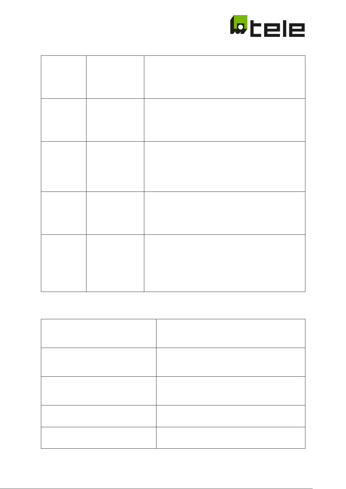
3.4 Comparators
Depending on the standard selected not all comparators can be processed.
Subject to modifications and errors Page 15 of 71 2019-06-26 edition
Page 16
L3+N) coupling mode!
L3+N) coupling mode!
Line to Neutral
Overvoltage 1
All 3 phase-to-neutral voltages are monitored according to the
Can be deactivated in 3-phase (L1, L2, L3) coupling mode!
Line to Neutral
Undervoltage 1
All 3 phase-to-neutral voltages are monitored according to the
Can be deactivated in 3-phase (L1, L2, L3) coupling mode!
Average
Overvoltage
The 10-minutes average generated is monitored according to
In 4-phase coupling mode: L1-N; L2-N; L3-N
Overfrequency 1
Overfrequency 4
The frequency of the 3 phase-to-neutral voltages are
Underfrequency 1
Underfrequency 4
The frequencies of the 3 phase-to-neutral voltages are
Exception: in 2-wire mode only U L1-N
Random over frequency
The frequency of the 3 phase-to-neutral voltages are
Exception: in 2-wire mode only U L1-N
Frequency monitoring undervoltage LL
Depending on the mode (2-, 3-, 4-wire,) falling below the
comparators.
RoCoF
The frequency change rates of the 3 phase-to-neutral
Exception: in 2-wire mode only U L1-N
3.4.1 Voltage monitoring
Line to line Overvoltage 1
Overvoltage 2
All 3 phase to phase voltages are monitored according to the
set overvoltage thresholds!
After exceeding the switching threshold, the device triggers
after the set trigger delay t
.
off
Can be deactivated in 2-phase (L+N) as well as 4-phase (L1, L2,
Line to line Undervoltage 1
Undervoltage 2
Overvoltage 2
Undervoltage 2
All 3 phase to phase voltages are monitored according to the
undervoltage thresholds set!
After exceeding the switching threshold, the device triggers
after the set trigger delay t
.
off
Can be deactivated in 2-phase (L+N) as well as 4-phase (L1, L2-
overvoltage thresholds set!
After exceeding the switching threshold, the device triggers
after the set trigger delay toff.
Exception: In 2-phase (L+N) coupling mode, only one
overvoltage measurement takes place between L1 and N!
undervoltage thresholds set! After exceeding the switching
threshold, the device triggers after the set trigger delay toff.
Exception: In 2-phase (L+N) coupling mode, only one
overvoltage measurement takes place between L1 and N!
the switching thresholds set for the slow voltage increase
protection!
After exceeding the switching threshold, the device triggers
after the set trigger delay toff.
In 2-phase coupling mode: L-N
In 3-phase coupling mode: L1-L2-L3
3.4.2 Frequency monitoring
Overfrequency 2
Overfrequency 3
Underfrequency 2
Underfrequency 3
Frequency monitoring undervoltage LN
monitored according to the overvoltage thresholds set.
Exception: in 2-wire mode only U L1-N
monitored according to the under-frequency thresholds
set.
monitored according to the parameters set (random max.
frequency).
set threshold leads to the deactivation of the frequency
voltages are monitored according to the parameters set.
Subject to modifications and errors Page 16 of 71 2019-06-26 edition
Page 17
Phase Shift
The phase shift behavior of the 3 phase-to-neutral
Selection
This comparator is activated
Name
Text displayed when editing parameter
Visible
This selection is visible on the display
Base 1)
A modification of this selection is shown
Disabled
Selection of which combination of digital inputs or modes
leads to disabling of this comparator
1) … For changes within the normative allowed range, an "edit" will be displayed for "edited"
Turn-off threshold
Shutdown threshold in %Unom, Hz, mHz/s or °
Name
Text displayed when editing parameter
Changeable
This threshold can be changed by the user
Base 1)
A change of this threshold is displayed
Hysteresis
Is the associated turn-on threshold fixed or connected
with turn-off threshold via hysteresis
Offset
Offset of the actual turn-off threshold to value displayed
Increment/decrement setting
Change of the value per keystroke
allowed minimum normative setting 1)
Permissible minimum setting as per standard
allowed minimum tech setting 1)
Permissible minimum setting
allowed minimum tech setting 1)
Permissible maximum setting
1) … For changes within the normative allowed range, an "edit" will be displayed for "edited"
Turn-on threshold
Shutdown threshold in %Unom, Hz, mHz/s or °
Name
Text displayed when editing parameter
Changeable
This threshold can be changed by the user
Base 1)
A change of this threshold is displayed
Hysteresis
Is the associated turn-off threshold fixed or connected
with this turn-on threshold via hysteresis
Offset/hysteresis
For fixed threshold: offset of the actual turn-off threshold
turn-off threshold
allowed minimum normative setting 1)
Permissible minimum setting as per standard
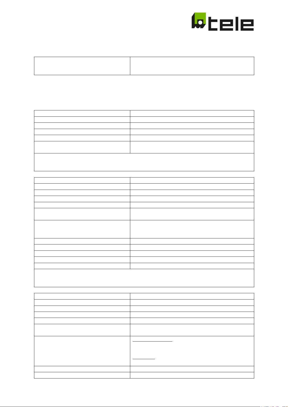
3.4.3 Phase shift monitoring
voltages are monitored according to the parameters set.
Exception: in 2-wire mode only U L1-N
3.5 Configuration
The following can be configured for each of the comparators above:
Changeable This selection can be changed by the user
(Exception: setting for base = 1) … for changes outside the normative allowed range, "ncnf" will be displayed for
"non conform"
Visible This threshold is shown on the display
(is subtracted for max. thresholds, added for min.
thresholds)
allowed maximum normative setting 1) Permissible maximum setting as per standard
(Exception: setting for base = 1) … for changes outside the normative allowed range, "ncnf" will be displayed for
"non conform"
Visible This threshold is shown on the display
to the value displayed (is subtracted for max. thresholds,
added for min. thresholds)
Hysteresis: Difference between turn-on threshold and
Increment/decrement setting Change of the value per keystroke
Subject to modifications and errors Page 17 of 71 2019-06-26 edition
Page 18
allowed maximum normative setting 1)
Permissible maximum setting as per standard
allowed minimum tech setting 1)
Permissible minimum setting
1) … For changes within the normative allowed range, an "edit" will be displayed for "edited"
"non conform"
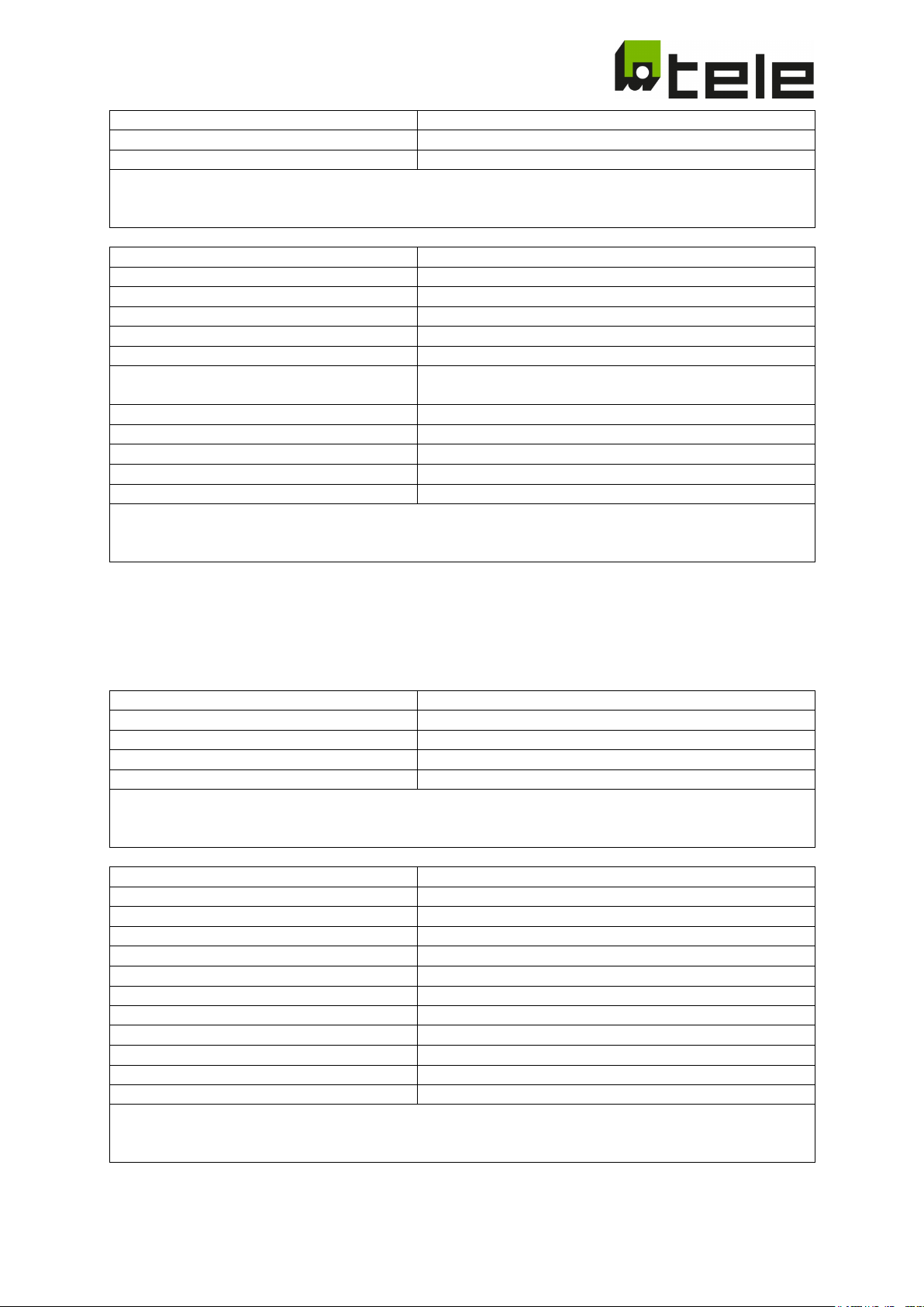
Turn-off delay
Turn-off time in ms
Name
Text displayed when editing parameter
Visible
This time is visible on the display
Base 1)
A change to this time is displayed
Hysteresis
n.a. (always 0)
Offset/hysteresis
In ms … is deducted from the set time (compensation of
the measuring time)
Increment/decrement setting
Change of the value per keystroke
allowed minimum normative setting 1)
Permissible minimum setting as per standard
allowed maximum normative setting 1)
Permissible maximum setting as per standard
allowed minimum tech setting 1)
Permissible minimum setting
allowed minimum tech setting 1)
Permissible maximum setting
1) … For changes within the normative allowed range, an "edit" will be displayed for "edited"
"non conform"
Selection
Must always be 1
Name
Text displayed when editing parameter
Changeable
This selection can be changed by the user
Base 1)
A modification of this selection is shown
1) … For changes within the normative allowed range, an "edit" will be displayed for "edited"
Type
Normally closed (0), normally opened(1), n.a. (2)
Name
Text displayed when editing parameter
Changeable
This parameter can be changed by the user
Base 1)
A change to this parameter is displayed
Hysteresis
n.a. (always 0)
Increment/decrement setting
Always 1
allowed minimum normative setting 1)
Permissible minimum setting as per standard
allowed maximum normative setting 1)
Permissible maximum setting as per standard
allowed minimum tech setting 1)
Permissible maximum setting
1) … For changes within the normative allowed range, an "edit" will be displayed for "edited"
allowed minimum tech setting 1) Permissible maximum setting
(Exception: setting for base = 1) … for changes outside the normative allowed range, "ncnf" will be displayed for
Changeable This time can be changed by the user
(Exception: setting for base = 1) … for changes outside the normative allowed range, "ncnf" will be displayed for
3.6 Other Parameter
3.6.1 Feedback contact
Visible This selection is visible on the display
(Exception: setting for base = 1) … for changes outside the normative allowed range, "ncnf" will be displayed for
"non conform"
Visible This parameter is visible on the display
Offset n.a. (always 0)
allowed minimum tech setting 1) Permissible minimum setting
(Exception: setting for base = 1) … for changes outside the normative allowed range, "ncnf" will be displayed for
"non conform"
Subject to modifications and errors Page 18 of 71 2019-06-26 edition
Page 19
Turn-off delay
Maximum permissible switching time of the auxiliary
contact
Name
Text displayed when editing parameter
Visible
This time is visible on the display
Changeable
This time can be changed by the user
Base 1)
A change to this time is displayed
Hysteresis
n.a. (always 0)
Offset/hysteresis
In ms … is deducted from the set time (compensation of
the measuring time)
Increment/decrement setting
Change of the value per keystroke
allowed maximum normative setting 1)
Permissible maximum setting as per standard
allowed minimum tech setting 1)
Permissible minimum setting
allowed minimum tech setting 1)
Permissible maximum setting
"non conform"
Selection
Turn-on time is active
Name
Text displayed when editing parameter
Visible
This selection is visible on the display
Base 1)
A modification of this selection is shown
1) … For changes within the normative allowed range, an "edit" will be displayed for "edited"
Definition
Turn-on delay
Name
Text displayed when editing parameter
Changeable
This parameter can be changed by the user
Base 1)
A change to this parameter is displayed
Hysteresis
n.a. (always 0)
Increment/decrement setting
Always 1
allowed minimum normative setting 1)
Permissible minimum setting as per standard
allowed maximum normative setting 1)
Permissible maximum setting as per standard
allowed minimum tech setting 1)
Permissible maximum setting
1) … For changes within the normative allowed range, an "edit" will be displayed for "edited"
Selection
Name
Text displayed when editing parameter
Visible
This selection is visible on the display
Changeable
This selection can be changed by the user
Base 1)
A modification of this selection is shown
allowed minimum normative setting 1) Permissible minimum setting as per standard
1) … For changes within the normative allowed range, an "edit" will be displayed for "edited"
(Exception: setting for base = 1) … for changes outside the normative allowed range, "ncnf" will be displayed for
3.6.2 Turn-on delay
Changeable This selection can be changed by the user
(Exception: setting for base = 1) … for changes outside the normative allowed range, "ncnf" will be displayed for
"non conform"
Visible This parameter is visible on the display
Offset n.a. (always 0)
allowed minimum tech setting 1) Permissible minimum setting
(Exception: setting for base = 1) … for changes outside the normative allowed range, "ncnf" will be displayed for
"non conform"
3.6.3 Random turn-on delay
Random turn-on time is active
Subject to modifications and errors Page 19 of 71 2019-06-26 edition
Page 20
1) … For changes within the normative allowed range, an "edit" will be displayed for "edited"
Definition
Is ignored
Name
Text displayed when editing parameter
Changeable
This parameter can be changed by the user
Base 1)
A change to this parameter is displayed
Hysteresis
n.a. (always 0)
Increment/decrement setting
Always 1
allowed minimum normative setting 1)
The minimum value of the random time
allowed maximum normative setting 1)
The maximum value of the random time
allowed minimum tech setting 1)
The maximum value of the random time
1) … For changes within the normative allowed range, an "edit" will be displayed for "edited"
"non conform"
Selection
Must always be 1
Visible
This selection is visible on the display
Changeable
This selection can be changed by the user
Base 1)
A modification of this selection is shown
"non conform"
Type
evaluated)
Name
Text displayed when editing parameter
Changeable
This parameter can be changed by the user
Base 1)
A change to this parameter is displayed
Hysteresis
n.a. (always 0)
Offset
n.a. (always 0)
Increment/decrement setting
Always 1
allowed minimum normative setting 1)
The minimum value of the random time
allowed maximum normative setting 1)
The maximum value of the random time
allowed minimum tech setting 1)
The minimum value of the random time
allowed minimum tech setting 1)
The maximum value of the random time
1) … For changes within the normative allowed range, an "edit" will be displayed for "edited"
"non conform"
(Exception: setting for base = 1) … for changes outside the normative allowed range, "ncnf" will be displayed for
"non conform"
Visible This parameter is visible on the display
Offset n.a. (always 0)
allowed minimum tech setting 1) The minimum value of the random time
(Exception: setting for base = 1) … for changes outside the normative allowed range, "ncnf" will be displayed for
3.6.4 Connection Mode
Name Text displayed when editing parameter
1) … For changes within the normative allowed range, an "edit" will be displayed for "edited"
(Exception: setting for base = 1) … for changes outside the normative allowed range, "ncnf" will be displayed for
[0] … 2-wire (L1, N … only one phase-to-neutral voltage is
evaluated)
[1] … 3-wire (L1, L2, L3 … only the phase voltages are
evaluated)
[2] … 4-wire (only phase-to-neutral voltages are evaluated)
[3] … 4-wire (only phase-to-neutral and phase voltages are
Visible This parameter is visible on the display
(Exception: setting for base = 1) … for changes outside the normative allowed range, "ncnf" will be displayed for
Subject to modifications and errors Page 20 of 71 2019-06-26 edition
Page 21
Selection
Name
Text displayed when editing parameter
Visible
This selection is visible on the display
Changeable
This selection can be changed by the user
1) … For changes within the normative allowed range, an "edit" will be displayed for "edited"
"non conform"
Value
Value of the nominal voltage
Name
Text displayed when editing parameter
Visible
This parameter is visible on the display
Changeable
This parameter can be changed by the user
Base 1)
A change to this parameter is displayed
Hysteresis
n.a. (always 0)
Offset
n.a. (always 0)
Increment/decrement setting
Always 1
allowed maximum normative setting 1)
The maximum value of the random time
allowed minimum tech setting 1)
The minimum value of the random time
allowed minimum tech setting 1)
The maximum value of the random time
"non conform"
Selection
Must always be 1
Name
Text displayed when editing parameter
Changeable
This selection can be changed by the user
Base 1)
A modification of this selection is shown
1) … For changes within the normative allowed range, an "edit" will be displayed for "edited"
"non conform"
Value
[0] … 2 contactors are monitored
[1] … only 1 contactor is monitored
Name
Text displayed when editing parameter
Visible
This parameter is visible on the display
Changeable
This parameter can be changed by the user
Base 1)
A change to this parameter is displayed
Hysteresis
n.a. (always 0)
Offset
n.a. (always 0)
Increment/decrement setting
Always 1
allowed minimum normative setting 1)
The minimum value of the random time
allowed maximum normative setting 1)
The maximum value of the random time
allowed minimum tech setting 1)
The minimum value of the random time
allowed minimum tech setting 1)
The maximum value of the random time
1) … For changes within the normative allowed range, an "edit" will be displayed for "edited"
"non conform"
3.6.5 Nominal Voltage
Must always be 1
Base 1) A modification of this selection is shown
(Exception: setting for base = 1) … for changes outside the normative allowed range, "ncnf" will be displayed for
allowed minimum normative setting 1) The minimum value of the random time
1) … For changes within the normative allowed range, an "edit" will be displayed for "edited"
(Exception: setting for base = 1) … for changes outside the normative allowed range, "ncnf" will be displayed for
3.6.6 Functional Safety
Visible This selection is visible on the display
(Exception: setting for base = 1) … for changes outside the normative allowed range, "ncnf" will be displayed for
(Exception: setting for base = 1) … for changes outside the normative allowed range, "ncnf" will be displayed for
Subject to modifications and errors Page 21 of 71 2019-06-26 edition
Page 22
Selection
Name
Text displayed when editing parameter
Visible
This selection is visible on the display
Changeable
This selection can be changed by the user
1) … For changes within the normative allowed range, an "edit" will be displayed for "edited"
"non conform"
Value
[0] …. mode 0 2)
Name
Text displayed when editing parameter
Visible
This parameter is visible on the display
Changeable
This parameter can be changed by the user
Base 1)
A change to this parameter is displayed
Hysteresis
n.a. (always 0)
Offset
n.a. (always 0)
Increment/decrement setting
Always 1
allowed minimum normative setting 1)
The minimum value of the random time
allowed maximum normative setting 1)
The maximum value of the random time
allowed minimum tech setting 1)
The minimum value of the random time
allowed minimum tech setting 1)
The maximum value of the random time
1) … For changes within the normative allowed range, an "edit" will be displayed for "edited"
switching between standard and transitory mode
3.6.7 Operational Mode
Must always be 1
Base 1) A modification of this selection is shown
(Exception: setting for base = 1) … for changes outside the normative allowed range, "ncnf" will be displayed for
[1] …. mode 1
(Exception: setting for base = 1) … for changes outside the normative allowed range, "ncnf" will be displayed for
"non conform"
2) … comparators can be activated or deactivated via this selector. Currently only used for the CEI 0-21 for
Subject to modifications and errors Page 22 of 71 2019-06-26 edition
Page 23

3.7 Settings of the implemented configurations
Definition for the following tables:
Lines highlighted in gray mean that the associated parameters can be edited. All other settings are fixed.
Connection Modes
2-wire Only the voltage between L1 and N is evaluated
3-wire Only the line to line voltages U
4-wire (LN) Only the phase-to-neutral voltages U
4-wire (LN+LL) Both the phase-to-neutral voltages U
phase voltages U
L1-L2
, U
L2-L3
Units
%Unom Percent of the nominal voltage (nominal voltage factor)
Functional safety
Errtol 2ch 2 separated contactors with 2 separated auxiliary contacts are connected
Errtol 1ch 1 external contactor with 1 auxiliary contact is connected
Operational mode
It is possible to switch between 2 different operating modes
Is currently only used for the CEI-021 … see CEI-021 8.6.2.1.1
Mode 0: transitory mode
Mode 1: definitive mode
Thresholds
U
OFF Voltage threshold for the turn-off
THR
U
ON Voltage threshold for turn-on
THR
f
OFF Frequency threshold for the turn-off
THR
f
ON Frequency threshold for turn-on
THR
RoCoF
RoCoF
PShift
PShift
OFF Frequency change threshold for the turn-off
THR
ON Frequency change threshold for turn-on
THR
OFF Phase shift threshold for the turn-off
THR
ON Phase shift threshold for turn-on
THR
Times
Time OFF Turn-off delay
T on delay Turn-on delay
Auxiliary contact
Read back of the position of the actuated contactors (via positively-driven auxiliary contacts) is required for
the necessary functional safety. The following can be selected for these auxiliary contacts:
Contact n.c. (normally closed) Auxiliary contact is normally opened (recommended implementation)
Contact n.o. (normally opened) Auxiliary contact is normally closed
Contact dis. (disabled) Auxiliary contact is ignored (impermissible for standards that require
functional safety)
Ranges
Conformity range Within this range, the device is configured in compliance with the selected
standards. Outside of these ranges, the device is no longer compliant with
standards and the corresponding certificates lose their validity. This status is
shown on the display by the identifier "ncnf." Settings outside of this range are
therefore within the operator's scope of responsibility and/or the acceptance
authority of the system.
Possible range Technically possible setting range
L1-L2
, and U
, U
and U
L2-L3
, U
L1-N
L2-N,
, U
L1-N
L2-N,
are evaluated
L3-L1
are evaluated
L3-L1
and U
L3-N
and U
L3-N
are evaluated
as well as the phase to
Subject to modifications and errors Page 23 of 71 2019-06-26 edition
Page 24
ID Default
.003
Connection
4-wire (LN)
2-wire, 3-wire, 4-wire (LN)
2-wire, 3-wire,
ID Default
.009
Mode
1 (transitory)
0 (transitory), 1 (definitive)
0 (transitory), 1 (definitive)
Overvoltage1 Line to Line
Conformity Range
Possible Range
ID Default
Min
Max
Min
Max
.011
V 59.S2 LL
U
THR
OFF
%Unom
115
100
130
100
135
U
THR
ON
%Unom
Fixed Hysteresis (4% U
THR
)
Only active for:
Connection Modes: 3-wire, 4-wire (LN+LL)
Undervoltage1 Line to Line
Conformity Range
Possible Range
ID Default
Min
Max
Min
Max
THR
.017
T 27.S1 LL
Time OFF
Ms
400
50
5.000
50
10.000
U
THR
ON
% Unom
Fixed Hysteresis (4% U
THR
)
Only active for:
Connection Modes: 3-wire, 4-wire (LN+LL)
Overvoltage1 Line to Neutral
Conformity Range
Possible Range
ID Default
Min
Max
Min
Max
THR
.021
T 59.S2 LN
Time OFF
Ms
200
50
1.000
50
10.000
U
THR
ON
%Unom
Fixed Hysteresis (4% U
THR
)
Only active for:
Connection Modes: 2-wire, 4-wire (LN), 4-wire (LN+LL)
Undervoltage1 Line to Neutral
Conformity Range
Possible Range
ID Default
Min
Max
Min
Max
THR
.025
T 27.S1 LN
Time OFF
Ms
400
50
5.000
50
10.000
U
THR
ON
% Unom
Fixed Hysteresis (4% U
THR
)
Only active for:
Connection Modes: 2-wire, 4-wire (LN), 4-wire (LN+LL)
Undervoltage2 Line to Line
Conformity Range
Possible Range
ID Default
Min
Max
Min
Max
.031
V 27.S2 LL
U
THR
OFF
%Unom
40 0 100 0 100
.033
T 27.S2 LL
Time OFF
Ms
200
50
5.000
50
10.000
U
THR
ON
% Unom
Fixed Hysteresis (4% U
THR
)
Only active for:
Connection Modes: 3-wire, 4-wire (LN+LL)
Undervoltage2 Line to Neutral
Conformity Range
Possible Range
.039
V 27.S2 LN
U
THR
OFF
%Unom
40 0 100 0 100
.041
T 27.S2 LN
Time OFF
Ms
200
50
5.000
50
10.000
U
THR
ON
% Unom
Fixed Hysteresis (4% U
THR
)
3.7.1 CEI 0-21
Connection Mode Conformity Range Possible Range
4-wire (LN), 4-wire(LN+LL)
Operational Mode Conformity Range Possible Range
.013 T 59.S2 LL Time OFF Ms 200 50 1.000 50 10.000
.015 V 27.S1 LL U
.019 V 59.S2 LN U
.023 V 27.S1 LN U
OFF % Unom 85 20 100 0 100
OFF %Unom 115 100 130 100 135
OFF %Unom 85 20 100 0 100
ID Default Min Max Min Max
Only active for: Connection Modes: 2-wire, 4-wire (LN), 4-wire (LN+LL)
Subject to modifications and errors Page 24 of 71 2019-06-26 edition
Page 25
10 minutes average overvoltage
Conformity Range
Possible Range
ID Default
Min
Max
Min
Max
THR
.045
T 59.S1
Time OFF
Ms
0 0 0
0
10.000
U
THR
ON
% Unom
Fixed Hysteresis (4% U
THR
)
Overfrequency 1
Conformity Range
Possible Range
ID Default
Min
Max
Min
Max
.055
F 81>S2 ws
f
THR
OFF
Hz
51,50
50,0
52,0
50,0
55,0
f
THR
ON
Hz
Fixed Hysteresis (0,2% f
THR
)
Only active for:
Operational Mode 0 (definitive mode) when DigIn4 is inactive (contact open)
Voltage > 20% Unom
Underfrequency1
Conformity Range
Possible Range
ID Default
Min
Max
Min
Max
THR
.061
T 81<S2 ws
Time OFF
Ms
4000
50
5.000
50
10.000
f
THR
ON
Hz
Fixed Hysteresis (0,2% f
THR
)
Only ctive for:
Operational Mode 0 (definitive mode) when DigIn4 is inactive (contact open)
Voltage > 20% Unom
Overfrequency2
Conformity Range
Possible Range
ID Default
Min
Max
Min
Max
.063
F 81>S1 nf
f
THR
OFF
Hz
50,50
50,0
52,0
50,0
55,0
f
THR
ON
Hz
Fixed Hysteresis (0,2% f
THR
)
Only active for:
Operational Mode 0 (definitive mode) when DigIn 4 is active
Underfrequency2
Conformity Range
Possible Range
ID Default
Min
Max
Min
Max
.067
F 81<S1 nf
f
THR
OFF
Hz
49,50
47,0
50,0
45,0
50,0
.069
T 81<S1 nf
Time OFF
Ms
100
50
5.000
50
10.000
f
THR
ON
Hz
Fixed Hysteresis (0,2% f
THR
)
Only active for:
Operational Mode 0 (definitive mode) when DigIn 4 is active
Voltage > 20% Unom
Overfrequency3
Conformity Range
Possible Range
ID Default
Min
Max
Min
Max
.071
F 81>S2 wf
f
THR
OFF
Hz
51,50
50,0
52,0
50,0
55,0
.073
T 81>S2 wf
Time OFF
Ms
100
50
5.000
50
10.000
f
THR
ON
Hz
Fixed Hysteresis (0,2% f
THR
)
Only active for:
Operational Mode 1 (transitory mode) when DigIn 5 is inactive
Voltage > 20% Unom
Underfrequency3
Conformity Range
Possible Range
ID Default
Min
Max
Min
Max
.075
F 81<S2 wf
f
THR
OFF
Hz
47,50
47,0
50,0
45,0
50,0
f
THR
ON
Hz
Fixed Hysteresis (0,2% f
THR
)
Only active for:
Operational Mode 1 (transitory mode) when DigIn 5 is inactive
.043 V 59.S1 U
OFF %Unom 110 100 120 100 135
.057 T 81>S2 ws Time OFF Ms 1000 50 5.000 50 10.000
.059 F 81<S2 ws f
OFF Hz 47,50 47,0 50,0 45,0 50,0
.065 T 81>S1 nf Time OFF Ms 100 50 5.000 50 10.000
Operational Mode 1 (transitoty mode) when DigIn 5 is active
Voltage > 20% Unom
Operational Mode 1 (transitoty mode) when DigIn 5 is active
.077 T 81<S2 wf Time OFF Ms 100 50 5.000 50 10.000
Voltage > 20% Unom
Subject to modifications and errors Page 25 of 71 2019-06-26 edition
Page 26
Auxiliary Contact type
Conformity Range
Possible Range
ID
Default
dis. (disabled)
Turn on Delay
Conformity Range
Possible Range
ID Default
Min
Max
Min
Max
.102
T on delay S 5 0 300 0 600
ID
.105
ID: xxxxxx
xxxxx = Device ID
b: Version of the Configuration set
Password
ID Default
Min
Max
.107
PW2
2nd digit of Password
0 0 9
.108
PW3
3rd digit of Password
0 0 9
.109
PW4
4th digit of Password
0 0 9
.099 Contact n.c. (normally closed) n.o. (normally opened)
n.c. (normally closed)
n.o. (normally opened)
n.c. (normally closed)
Device Information
SW: aa.dd.ccb
dd: Software version of Display Software
aa: Software version of Measuring Software
cc: Index of the Configuration set
.106 PW1 1st digit of Password 0 0 9
Remark: If all 4 digits of the Password are 0 (default setting) the Password request is skipped
Subject to modifications and errors Page 26 of 71 2019-06-26 edition
Page 27
Overvoltage1 Line to Line
Conformity Range
Possible Range
ID Default
Min
Max
Min
Max
.011
ULLmax off
U
THR
OFF
%Unom
115
115
115
100
135
.012
ULLmax on
U
THR
ON
%Unom
110
110
110
100
135
Time OFF
Fixed to a fastest possible disconnection
Undervoltage1 Line to Line
Conformity Range
Possible Range
ID Default
Min
Max
Min
Max
THR
.016
ULLmin on
U
THR
ON
%Unom
85
85
85
10
100
Time OFF
Fixed to a fastest possible disconnection
Overvoltage1 Line to Neutral
Conformity Range
Possible Range
ID Default
Min
Max
Min
Max
.019
U >> off
U
THR
OFF
%Unom
115
115
115
100
135
.020
U >> on
U
THR
ON
%Unom
110
110
110
100
135
Time OFF
Fixed to a fastest possible disconnection
Undervoltage1 Line to Neutral
Conformity Range
Possible Range
ID Default
Min
Max
Min
Max
.023
U < off
U
THR
OFF
%Unom
80
80
80
10
100
.024
U < on
U
THR
ON
%Unom
85
85
85
10
100
Time OFF
Fixed to a fastest possible disconnection
ID Default
Min
Max
Min
Max
.043
U>
U
THR
OFF
%Unom
110
110
115
100
135
U
THR
ON
% Unom
Fixed Hysteresis (1% U
NOM
)
Overfrequency 1
Conformity Range
Possible Range
.055
f > off
f
THR
OFF
Hz
51,50
51,50
51,50
50,00
55,00
.056
F > on
f
THR
ON
Hz
50,05
50,05
50,05
50,00
55,00
Time OFF
Fixed to a fastest possible disconnection
Underfrequency1
Conformity Range
Possible Range
.059
f < off
f
THR
OFF
Hz
47,50
47,50
47,50
45,00
50,00
.060
f < on
f
THR
ON
ms
47,50
47,50
47,50
45,00
50,00
Time OFF
Fixed to a fastest possible disconnection
Comment:
f < on has a fixed offset of 0,025 Hz added to the displayed value
Random over frequency
Conformity Range
Possible Range
.086
f> random
Enable function
off
on … off
on … off
.087
f> random
f
THR
OFF
Hz 50.20
51.50
50.20
51.50
Time OFF
Fixed to a fastest possible disconnection
3.7.2 VDE 0126
.015 ULLmin off U
OFF % Unom 80 80 80 10 100
10 minutes average overvoltage Conformity Range Possible Range
Time OFF Fixed to a fastest possible disconnection
ID Default Min Max Min Max
ID Default Min Max Min Max
ID Default Min Max Min Max
Comment: The random threshold value is shown in .087 and cannot be edited
Subject to modifications and errors Page 27 of 71 2019-06-26 edition
Page 28
Auxiliary Contact type
Conformity Range
Possible Range
.099
Contact
n.c. (normally closed)
n.o. (normally opened)
n.o. (normally opened)
dis. (disabled)
Turn on Delay
Conformity Range
Possible Range
ID Default
Min
Max
Min
Max
Random Turn on delay
Conformity Range
Possible Range
ID Default
Min
Max
Min
Max
.103
Ton random
Enable function
off
on … off
on … off
.104
Ton random
Turn on time
s
60
600
60
600
Comment:
The random time value is shown in .104 and cannot be edited
Device Information
ID
.105
ID: xxxxxx
xxxxx = Device ID
b: Version of the Configuration set
Password
.106
PW1
1st digit of Password
0 0 9
.107
PW2
2nd digit of Password
0 0 9
.108
PW3
3rd digit of Password
0 0 9
.109
PW4
4th digit of Password
0 0 9
Remark:
If all 4 digits of the Password are 0 (default setting) the Password request is skipped
ID Default
n.c. (normally closed)
n.c. (normally closed)
.102 T on delay s 60 60 60 0 600
SW: aa.dd.ccb
dd: Software version of Display Software
aa: Software version of Measuring Software
cc: Index of the Configuration set
ID Default Min Max
Subject to modifications and errors Page 28 of 71 2019-06-26 edition
Page 29
Functional Safety
Conformity Range
Possible Range
ID Default
.007
Errtol
1ch
1ch
1ch, 2ch
Remark:
2ch means: 2 channel with functional safety and 2 auxiliary contacts necessary
1ch means: 1 channel without functional safety and 1 auxiliary contact1 necessary
Overvoltage1 Line to Line
Conformity Range
Possible Range
ID Default
Min
Max
Min
Max
.011
ULL >> off
U
THR
OFF
%Unom
115
115
115
115
115
THR
Time OFF
Fixed to a fastest possible disconnection
ID Default
Min
Max
Min
Max
.015
ULL << off
U
THR
OFF
%Unom
80
80
85
80
85
.016
ULL << on
U
THR
ON
%Unom
85
85
85
85
100
ID Default
Min
Max
Min
Max
.019
ULN >> off
U
THR
OFF
%Unom
115
115
115
115
115
.020
ULN >> on
U
THR
ON
%Unom
110
110
110
100
110
Undervoltage1 Line to Neutral
Conformity Range
Possible Range
.023
ULN < off
U
THR
OFF
%Unom
80
80
85
80
85
.024
ULN < on
U
THR
ON
%Unom
85
85
85
85
100
Time OFF
Fixed to a fastest possible disconnection
10 minutes average overvoltage
Conformity Range
Possible Range
ID Default
Min
Max
Min
Max
THR
U
THR
ON
% Unom
Fixed Hysteresis (1% U
NOM
)
Time OFF
Fixed to a fastest possible disconnection
Overfrequency 1
Conformity Range
Possible Range
ID Default
Min
Max
Min
Max
.055
f > off
f
THR
OFF
Hz
51,50
51,50
51,50
51,50
51,50
.056
f > on
f
THR
ON
Hz
50,1
50,1
50,1
50,00
50,1
Time OFF
Fixed to a fastest possible disconnection
Underfrequency1
Conformity Range
Possible Range
ID Default
Min
Max
Min
Max
.059
f < off
f
THR
OFF
Hz
47,50
47,50
47,50
47,50
47,50
THR
Time OFF
Fixed to a fastest possible disconnection
Comment:
f < on has a fixed offset of 0,025 Hz added to the displayed value
3.7.3 VDE-AR-N 4105 (Pn ≤ 50kW)
.012 ULL >> on U
ON %Unom 110 110 110 100 110
Undervoltage1 Line to Line Conformity Range Possible Range
Time OFF Fixed to a fastest possible disconnection
Overvoltage1 Line to Neutral Conformity Range Possible Range
Time OFF Fixed to a fastest possible disconnection
ID Default Min Max Min Max
.043 U > off U
OFF %Unom 110 110 115 110 115
.060 f < on f
Subject to modifications and errors Page 29 of 71 2019-06-26 edition
ON ms 47,50 47,50 47,50 47,50 50,00
Page 30
Random over frequency
Conformity Range
Possible Range
ID Default
Min
Max
Min
Max
.087
f > random
f
THR
OFF
Hz 50.20
51.50
50.20
51.50
Time OFF
Fixed to a fastest possible disconnection
Comment:
The random threshold value is shown in .087 and cannot be edited
Auxiliary Contact type
Conformity Range
Possible Range
ID
Default
dis. (disabled)
Turn on Delay
Conformity Range
Possible Range
ID Default
Min
Max
Min
Max
.102
T on delay
s
60
60
60 0 600
Random Turn on delay
Conformity Range
Possible Range
ID Default
Min
Max
Min
Max
.103
Ton random
Enable function
off
on … off
on … off
.104
Ton random
Turn on time
s
60
600
60
600
Comment:
The random time value is shown in .104 and cannot be edited
Device Information
ID
b: Version of the Configuration set
Password
ID Default
Min
Max
.107
PW2
2nd digit of Password
1 0 9
.108
PW3
3rd digit of Password
0 0 9
.109
PW4
4th digit of Password
5 0 9
.086 f > random Enable function off on … off on … off
.099 Contact n.c. (normally closed) n.o. (normally opened)
n.c. (normally closed)
.105 ID: xxxxxx
SW: aa.dd.ccb
xxxxx = Device ID
dd: Software version of Display Software
aa: Software version of Measuring Software
cc: Index of the Configuration set
n.o. (normally opened)
n.c. (normally closed)
.106 PW1 1st digit of Password 4 0 9
Remark: If all 4 digits of the Password are 0 (default setting) the Password request is skipped
Subject to modifications and errors Page 30 of 71 2019-06-26 edition
Page 31
Functional Safety
Conformity Range
Possible Range
ID Default
.007
Errtol
1ch
1ch
1ch, 2ch
Remark:
2ch means: 2 channel with functional safety and 2 auxiliary contacts necessary
1ch means: 1 channel without functional safety and 1 auxiliary contact1 necessary
Overvoltage1 Line to Line
Conformity Range
Possible Range
ID Default
Min
Max
Min
Max
.011
ULL >> off
U
THR
OFF
%Unom
125
125
125
125
125
THR
Time OFF
Fixed to a fastest possible disconnection
ID Default
Min
Max
Min
Max
.015
ULL < off
U
THR
OFF
%Unom
80
80
80
80
80
.016
ULL < on
U
THR
ON
%Unom
85
85
85
85
100
ID Default
Min
Max
Min
Max
.019
ULN >> off
U
THR
OFF
%Unom
125
125
125
125
125
.020
ULN >> on
U
THR
ON
%Unom
110
110
110
100
110
Undervoltage1 Line to Neutral
Conformity Range
Possible Range
.023
ULN < off
U
THR
OFF
%Unom
80
80
80
80
80
.024
ULN < on
U
THR
ON
%Unom
85
85
85
85
100
.025
T ULN <
Time OFF
ms
1000
50
1000
50
10000
Undervoltage2 Line to Line
Conformity Range
Possible Range
ID Default
Min
Max
Min
Max
THR
.032
ULL << on
U
THR
ON
%Unom
85
85
85
85
100
.033
T ULL <<
Time OFF
ms
300
50
300
50
10000
Undervoltage2 Line to Neutral
Conformity Range
Possible Range
ID Default
Min
Max
Min
Max
.039
ULN << off
U
THR
OFF
%Unom
45
45
45
45
45
.040
ULN << on
U
THR
ON
%Unom
85
85
85
85
100
.041
T ULN <<
Time OFF
ms
300
50
300
50
10000
10 minutes average overvoltage
Conformity Range
Possible Range
ID Default
Min
Max
Min
Max
.043
U > off
U
THR
OFF
%Unom
110
110
115
110
115
THR
NOM
Time OFF
Fixed to a fastest possible disconnection
Overfrequency 1
Conformity Range
Possible Range
ID Default
Min
Max
Min
Max
.055
f > off
f
THR
OFF
Hz
51,50
51,50
51,50
51,50
51,50
.056
f > on
f
THR
ON
Hz
50,1
50,1
50,1
50,00
50,1
3.7.4 VDE-AR-N 4105 (Pn > 50kW)
.012 ULL >> on U
ON %Unom 110 110 110 100 110
Undervoltage1 Line to Line Conformity Range Possible Range
.017 T ULL < Time OFF ms 1000 50 1000 50 10000
Overvoltage1 Line to Neutral Conformity Range Possible Range
Time OFF Fixed to a fastest possible disconnection
ID Default Min Max Min Max
.031 ULL << off U
OFF %Unom 45 45 45 45 45
U
ON % Unom Fixed Hysteresis (1% U
Time OFF Fixed to a fastest possible disconnection
Subject to modifications and errors Page 31 of 71 2019-06-26 edition
)
Page 32
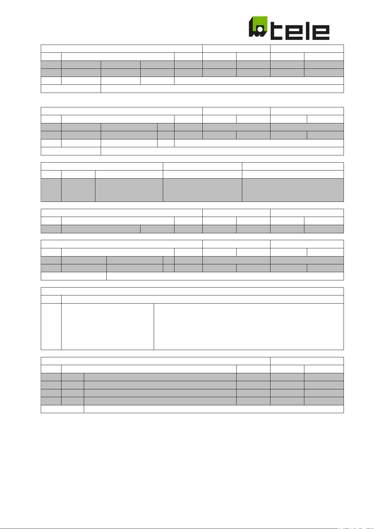
Underfrequency1
Conformity Range
Possible Range
ID Default
Min
Max
Min
Max
THR
.060
f < on
f
THR
ON
ms
47,50
47,50
47,50
47,50
50,00
Time OFF
Fixed to a fastest possible disconnection
Comment:
f < on has a fixed offset of 0,025 Hz added to the displayed value
ID Default
Min
Max
Min
Max
.086
f > random
Enable function
off
on … off
on … off
.087
f > random
f
THR
OFF
Hz 50.20
51.50
50.20
51.50
Time OFF
Fixed to a fastest possible disconnection
Comment:
The random threshold value is shown in .087 and cannot be edited
ID
Default
.099
Contact
n.c. (normally closed)
n.o. (normally opened)
n.o. (normally opened)
Turn on Delay
Conformity Range
Possible Range
.102
T on delay
s
60
60
60 0 600
Random Turn on delay
Conformity Range
Possible Range
ID Default
Min
Max
Min
Max
.103
Ton random
Enable function
off
on … off
on … off
.104
Ton random
Turn on time
s
60
600
60
600
Comment:
The random time value is shown in .104 and cannot be edited
Device Information
ID
.105
ID: xxxxxx
xxxxx = Device ID
b: Version of the Configuration set
ID Default
Min
Max
.106
PW1
1st digit of Password
4 0 9
.107
PW2
2nd digit of Password
1 0 9
.109
PW4
4th digit of Password
5 0 9
Remark:
If all 4 digits of the Password are 0 (default setting) the Password request is skipped
.059 f < off f
OFF Hz 47,50 47,50 47,50 47,50 47,50
Random over frequency Conformity Range Possible Range
Auxiliary Contact type Conformity Range Possible Range
n.c. (normally closed)
n.c. (normally closed)
dis. (disabled)
ID Default Min Max Min Max
Password
.108 PW3 3rd digit of Password 0 0 9
SW: aa.dd.ccb
dd: Software version of Display Software
aa: Software version of Measuring Software
cc: Index of the Configuration set
Subject to modifications and errors Page 32 of 71 2019-06-26 edition
Page 33
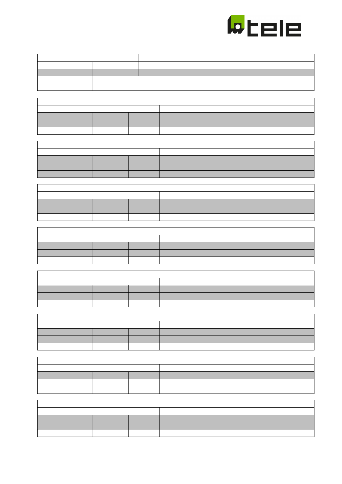
Functional Safety
Conformity Range
Possible Range
ID Default
.007
Errtol
2ch
2ch
1ch, 2ch
Remark:
2ch means: 2 channel with functional safety and 2 auxiliary contacts necessary
1ch means: 1 channel without functional safety and 1 auxiliary contact1 necessary
Overvoltage1 Line to Line
Conformity Range
Possible Range
ID Default
Min
Max
Min
Max
.011
ULL >> off
U
THR
OFF
%Unom
125
125
125
125
125
THR
Time OFF
Fixed to a fastest possible disconnection
ID Default
Min
Max
Min
Max
.015
ULL < off
U
THR
OFF
%Unom
80
80
80
80
80
.016
ULL < on
U
THR
ON
%Unom
85
85
85
85
100
ID Default
Min
Max
Min
Max
.019
ULN >> off
U
THR
OFF
%Unom
125
125
125
125
125
.020
ULN >> on
U
THR
ON
%Unom
110
110
110
100
110
Undervoltage1 Line to Neutral
Conformity Range
Possible Range
.023
ULN < off
U
THR
OFF
%Unom
80
80
80
80
80
.024
ULN < on
U
THR
ON
%Unom
85
85
85
85
100
Time OFF
Fixed to 3000ms
Undervoltage2 Line to Line
Conformity Range
Possible Range
ID Default
Min
Max
Min
Max
THR
.032
ULL << on
U
THR
ON
%Unom
85
85
85
85
100
Time OFF
Fixed to 300ms
Undervoltage2 Line to Neutral
Conformity Range
Possible Range
ID Default
Min
Max
Min
Max
.039
ULN << off
U
THR
OFF
%Unom
45
45
45
45
45
.040
ULN << on
U
THR
ON
%Unom
85
85
85
85
100
Time OFF
Fixed to 300ms
10 minutes average overvoltage
Conformity Range
Possible Range
ID Default
Min
Max
Min
Max
.043
U > off
U
THR
OFF
%Unom
110
110
115
110
115
THR
NOM
Time OFF
Fixed to a fastest possible disconnection
Overfrequency 1
Conformity Range
Possible Range
ID Default
Min
Max
Min
Max
.055
f > off
f
THR
OFF
Hz
51,50
51,50
51,50
51,50
51,50
.056
f > on
f
THR
ON
Hz
50,1
50,1
50,1
50,00
50,1
3.7.5 VDE-AR-N 4105 (Converter)
.012 ULL >> on U
ON %Unom 110 110 110 100 110
Undervoltage1 Line to Line Conformity Range Possible Range
.017 T ULL < Time OFF ms 3000 3000 3000 50 10000
Overvoltage1 Line to Neutral Conformity Range Possible Range
Time OFF Fixed to a fastest possible disconnection
ID Default Min Max Min Max
.031 ULL << off U
OFF %Unom 45 45 45 45 45
U
ON % Unom Fixed Hysteresis (1% U
Time OFF Fixed to a fastest possible disconnection
Subject to modifications and errors Page 33 of 71 2019-06-26 edition
)
Page 34
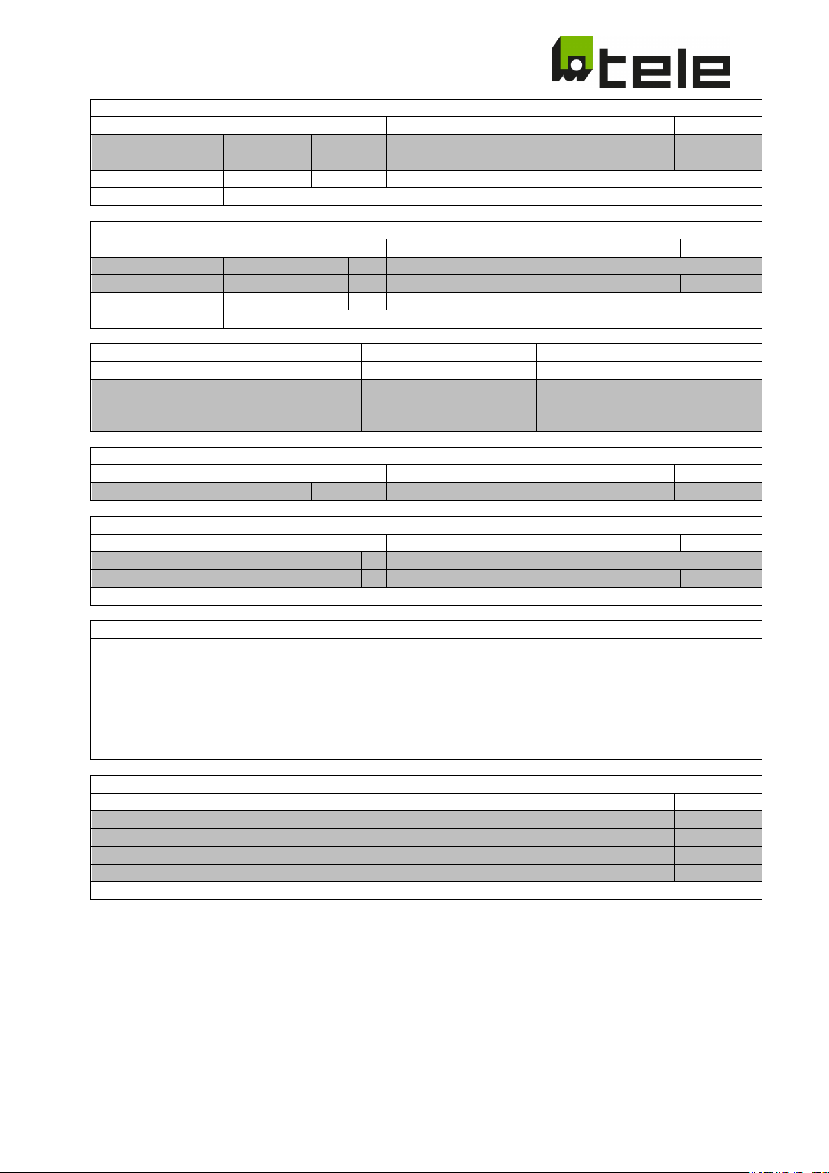
Underfrequency1
Conformity Range
Possible Range
ID Default
Min
Max
Min
Max
THR
.060
f < on
f
THR
ON
ms
47,50
47,50
47,50
47,50
50,00
Time OFF
Fixed to a fastest possible disconnection
Comment:
f < on has a fixed offset of 0,025 Hz added to the displayed value
Random over frequency
Conformity Range
Possible Range
ID Default
Min
Max
Min
Max
.087
f > random
f
THR
OFF
Hz 50.20
51.50
50.20
51.50
Time OFF
Fixed to a fastest possible disconnection
Comment:
The random threshold value is shown in .087 and cannot be edited
Auxiliary Contact type
Conformity Range
Possible Range
ID
Default
dis. (disabled)
Turn on Delay
Conformity Range
Possible Range
ID Default
Min
Max
Min
Max
.102
T on delay
s
60
60
60 0 600
Random Turn on delay
Conformity Range
Possible Range
.103
Ton random
Enable function
off
on … off
on … off
.104
Ton random
Turn on time
s
60
600
60
600
Comment:
The random time value is shown in .104 and cannot be edited
Device Information
ID
.105
ID: xxxxxx
xxxxx = Device ID
b: Version of the Configuration set
Password
.106
PW1
1st digit of Password
4 0 9
.107
PW2
2nd digit of Password
1 0 9
.108
PW3
3rd digit of Password
0 0 9
.109
PW4
4th digit of Password
5 0 9
Remark:
If all 4 digits of the Password are 0 (default setting) the Password request is skipped
.059 f < off f
OFF Hz 47,50 47,50 47,50 47,50 47,50
.086 f > random Enable function off on … off on … off
.099 Contact n.c. (normally closed) n.o. (normally opened)
n.c. (normally closed)
n.o. (normally opened)
n.c. (normally closed)
ID Default Min Max Min Max
SW: aa.dd.ccb
dd: Software version of Display Software
aa: Software version of Measuring Software
cc: Index of the Configuration set
ID Default Min Max
Subject to modifications and errors Page 34 of 71 2019-06-26 edition
Page 35
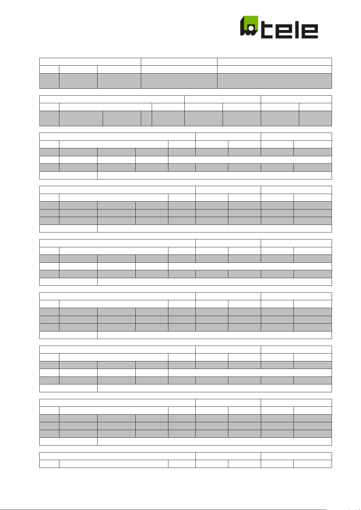
ID Default
.003
Connection
4-wire (LN)
3-wire, 4-wire (LN)
2-wire, 3-wire, 4-wire (LN),
ID Default
Min
Max
Min
Max
.005
ULN/LL nom
Unom Y
Unom Δ
V V 230.0
400.0
57,5
100.0
230.0
400.0
28,8
50.0
241.4
420.0
Overvoltage1 Line to Line
Conformity Range
Possible Range
ID Default
Min
Max
Min
Max
.011
ULL > off
U
THR
OFF
%Unom
110
100
130
100
135
U
THR
ON
Fixed Hysteresis (1% U
NOM
)
.013
T ULL >
Time OFF
ms
180000
100
180000
100
180000
Only active for:
Connection Modes: 3-wire, 4-wire (LN+LL)
Undervoltage1 Line to Line
Conformity Range
Possible Range
ID Default
Min
Max
Min
Max
.015
ULL < off
U
THR
OFF
%Unom
80
10
100
10
100
.016
ULL < on
U
THR
ON
%Unom
95
95
95
10
100
.017
T ULL <
Time OFF
ms
1500
1500
2400 0 60000
Only active for:
Connection Modes: 3-wire, 4-wire (LN+LL)
Overvoltage1 Line to Neutral
Conformity Range
Possible Range
ID Default
Min
Max
Min
Max
.019
ULN > off
U
THR
OFF
%Unom
110
100
130
100
135
THR
NOM
.021
T ULN >
Time OFF
ms
180000
100
180000
100
180000
Only active for:
Connection Modes: 2-wire, 4-wire (LN)
Undervoltage1 Line to Neutral
Conformity Range
Possible Range
ID Default
Min
Max
Min
Max
.023
ULN < off
U
THR
OFF
%Unom
80
10
100
10
100
THR
.025
T ULN <
Time OFF
ms
1500
1500
2400 0 60000
Only active for:
Connection Modes: 2-wire, 4-wire (LN)
Overvoltage2 Line to Line
Conformity Range
Possible Range
ID Default
Min
Max
Min
Max
.027
ULL >> off
U
THR
OFF
%Unom
125
100
130
100
135
U
THR
ON
Fixed Hysteresis (1% U
NOM
)
.029
T ULL >>
Time OFF
ms
100
100
100
100
10000
Only active for:
Connection Modes: 3-wire, 4-wire (LN+LL)
Undervoltage2 Line to Line
Conformity Range
Possible Range
ID Default
Min
Max
Min
Max
THR
.032
ULL << on
U
THR
ON
%Unom
95
95
95
10
100
.033
T ULL <<
Time OFF
ms
800
800
800
50
60000
Only active for:
Connection Modes: 3-wire, 4-wire (LN+LL)
Overvoltage2 Line to Neutral
Conformity Range
Possible Range
ID Default
Min
Max
Min
Max
3.7.6 VDE-AR-N 4110 (tested according to TR3, evaluation report TR8)
Connection Mode Conformity Range Possible Range
4-wire(LN+LL)
Nominal Voltage Conformity Range Possible Range
U
.024 ULN < on U
ON Fixed Hysteresis (1% U
)
ON %Unom 95 95 95 10 100
.031 ULL << off U
Subject to modifications and errors Page 35 of 71 2019-06-26 edition
OFF %Unom 30 10 100 10 100
Page 36
.035
ULN >> off
U
THR
OFF
%Unom
125
100
130
100
135
U
THR
ON
Fixed Hysteresis (1% U
NOM
)
Only active for:
Connection Modes: 2-wire, 4-wire (LN)
ID Default
Min
Max
Min
Max
.039
ULN << off
U
THR
OFF
%Unom
30
10
100
10
100
.040
ULN << on
U
THR
ON
%Unom
95
95
95
10
100
Only active for:
Connection Modes: 2-wire, 4-wire (LN)
Overfrequency1
Conformity Range
Possible Range
ID Default
Min
Max
Min
Max
THR
.056
f > on
f
THR
ON
Hz
50,1
50,1
50,1
50,0
55,0
.057
T f >
Time OFF
ms
5000
150
5000
150
10000
Underfrequency1
Conformity Range
Possible Range
ID Default
Min
Max
Min
Max
.059
f < off
f
THR
OFF
Hz
47,50
45,0
50,0
45,0
50,0
THR
.061
T f <
Time OFF
ms
50
50
70
50
10000
ID Default
Min
Max
Min
Max
.063
f >> off
f
THR
OFF
Hz
52,5
50,0
55,0
50,0
55,0
.064
f >> on
f
THR
ON
Hz
50,1
50,1
50,1
50,0
55,0
ID
Default
.099
Contact
dis. (disabled)
n.o. (normally opened)
dis. (disabled)
n.o. (normally opened)
dis. (disabled)
Turn on Delay
Conformity Range
Possible Range
.102
T on delay
s
60 0 60 0 1800
Device Information
ID
.105
ID: xxxxxx
xxxxx = Device ID
b: Version of Configuration set
Password
ID Default
Min
Max
.106
PW1
1st digit of Password
0 0 9
.107
PW2
2nd digit of Password
0 0 9
.108
PW3
3rd digit of Password
0 0 9
.037 T ULN >> Time OFF ms 100 100 100 100 10000
Undervoltage2 Line to Neutral Conformity Range Possible Range
.041 T ULN << Time OFF ms 800 800 800 50 60000
.055 f > off f
.060 f < on f
OFF Hz 51,5 50,0 55,0 50,0 55,0
ON Hz 49,9 49,9 49,9 45,0 50,0
Overfrequency2 Conformity Range Possible Range
.065 T f >> Time OFF ms 50 50 70 50 10000
Auxiliary Contact type Conformity Range Possible Range
n.c. (normally closed)
n.c. (normally closed)
ID Default Min Max Min Max
SW: aa.dd.ccb
Subject to modifications and errors Page 36 of 71 2019-06-26 edition
dd: Software version of Display Software
aa: Software version of Measuring Software
cc: Index of Configuration set
Page 37
.109
PW4
4th digit of Password
0 0 9
Remark:
If all 4 digits of the Password are 0 (default setting) the Password request is skipped
Nominal Voltage
Conformity Range
Possible Range
ID Default
Min
Max
Min
Max
.005
ULN/LL nom
Unom Y
Unom Δ
V V 230.0
400.0
230.0
400.0
240.0
417.4
100.0
173.9
240.0
417.4
Overvoltage1 Line to Neutral
Conformity Range
Possible Range
ID Default
Min
Max
Min
Max
.019
O/V st 1
U
THR
OFF
%Unom
114
114
114
100
135
U
THR
ON
Fixed Hysteresis (0,75% U
NOM
)
ID Default
Min
Max
Min
Max
.035
O/V st 2
U
THR
OFF
%Unom
119
119
119
100
135
.037
T O/V st 2
Time OFF
ms
500
500
500
50
300000
THR
NOM
ID Default
Min
Max
Min
Max
.039
U/V
U
THR
OFF
%Unom
80
80
80 0 100
.041
T U/V
Time OFF
ms
2500
2500
2500
50
300000
U
THR
ON
Fixed Hysteresis (0,75% U
NOM
)
Underfrequency1
Conformity Range
Possible Range
.059
U/F st 1
f
THR
OFF
Hz
47,5
47,5
47,5
40,0
50,0
.061
T U/F st 1
Time OFF
ms
20000
20000
20000
1000
300000
f
THR
ON
Fixed Hysteresis (0,05 Hz)
Overfrequency1
Conformity Range
Possible Range
ID Default
Min
Max
Min
Max
THR
.065
T O/F
Time OFF
ms
500
500
500
50
300000
f
THR
ON
Fixed Hysteresis (0,05 Hz)
Underfrequency2
Conformity Range
Possible Range
ID Default
Min
Max
Min
Max
.067
U/F st 2
f
THR
OFF
Hz
47,0
47,0
47,0
40,0
50,0
3.7.7 G99/1/3 LV (low voltage)
.021 T O/V st 1 Time OFF ms 1000 1000 1000 50 300000
Overvoltage2 Line to Neutral Conformity Range Possible Range
U
ON Fixed Hysteresis (0,75% U
)
Undervoltage1 Line to Neutral Conformity Range Possible Range
ID Default Min Max Min Max
.063 O/F f
Subject to modifications and errors Page 37 of 71 2019-06-26 edition
OFF Hz 52,0 52,0 52,0 50,0 55,0
Page 38
.069
T U/F st 2
Time OFF
ms
500
500
500
50
300000
f
THR
ON
Fixed Hysteresis (0,05 Hz)
Rate of Change of Frequency (RoCoF)
Conformity Range
Possible Range
ID Default
Min
Max
Min
Max
.091
RoCoF off
RoCoF
THR
OFF
mHz/s
1000
10
3000
10
3000
.092
RoCoF on
RoCoF
THR
ON
mHz/s
950
10
3000
10
3000
.093
RoCoFDelay
Time OFF
ms
500
50
500
50
2000
Phase Shift (PShift)
Conformity Range
Possible Range
ID Default
Min
Max
Min
Max
.095
PShift off
PShift
THR
OFF
°
12
--
-- 3 15
.096
PShift on
PShift
THR
ON
°
9
--
-- 3 15
Window
Fixed window length 200ms
Auxiliary Contact type
Conformity Range
Possible Range
ID
Default
.099
Contact
dis (disabled)
n.o. (normally opened)
dis. (disabled)
n.o. (normally opened)
dis. (disabled)
Turn on Delay
Conformity Range
Possible Range
ID Default
Min
Max
Min
Max
Device Information
.105
ID: xxxxxx
xxxxx = Device ID
Password
ID Default
Min
Max
.106
PW1
1st digit of Password
0 0 9
.107
PW2
2nd digit of Password
0 0 9
.108
PW3
3rd digit of Password
0 0 9
Remark:
If all 4 digits of the Password are 0 (default setting) the Password request is skipped
.090 RoCoF Enable Function On on / off on / off
Window Fixed window length 225ms
.094 PShift Enable Function Off on / off on / off
n.c. (normally closed)
n.c. (normally closed)
.102 T on delay s 20 20 20 0 600
ID
SW: aa.dd.ccb
dd: Software version of Display Software
aa: Software version of Measuring Software
cc: Index of the Configuration set
b: Version of the Configuration set
.109 PW4 4th digit of Password 0 0 9
Subject to modifications and errors Page 38 of 71 2019-06-26 edition
Page 39
Nominal Voltage
Conformity Range
Possible Range
.005
ULN/LL nom
Unom Y
V V 230.0
57.5
230.0
28.8
241.4
ID Default
Min
Max
Min
Max
.011
O/V st 1
U
THR
OFF
%Unom
110
110
110
100
135
.013
T O/V st 1
Time OFF
ms
1000
1000
1000
50
300000
U
THR
ON
Fixed Hysteresis (0,75% U
NOM
)
Overvoltage2 Line to Line
Conformity Range
Possible Range
.027
O/V st 2
U
THR
OFF
%Unom
113
113
113
100
135
.029
T O/V st 2
Time OFF
ms
500
500
500
50
300000
U
THR
ON
Fixed Hysteresis (0,75% U
NOM
)
Undervoltage2 Line to Line
Conformity Range
Possible Range
ID Default
Min
Max
Min
Max
THR
.033
T U/V
Time OFF
ms
2500
2500
2500
50
300000
U
THR
ON
Fixed Hysteresis (0,75% U
NOM
)
Underfrequency1
Conformity Range
Possible Range
ID Default
Min
Max
Min
Max
THR
.061
T U/F st 1
Time OFF
ms
20000
20000
20000
1000
300000
f
THR
ON
Fixed Hysteresis (0,05 Hz)
Overfrequency1
Conformity Range
Possible Range
ID Default
Min
Max
Min
Max
.063
O/F
f
THR
OFF
Hz
52,0
52,0
52,0
50,0
55,0
f
THR
ON
Fixed Hysteresis (0,05 Hz)
ID Default
Min
Max
Min
Max
.067
U/F st 2
f
THR
OFF
Hz
47,0
47,0
47,0
40,0
50,0
3.7.8 G99/1/3 HV (medium/high voltage)
ID Default Min Max Min Max
Unom Δ
400.0
100.0
400
50.0
420.0
Overvoltage1 Line to Line Conformity Range Possible Range
ID Default Min Max Min Max
.031 U/V U
.059 U/F st 1 f
OFF %Unom 80 80 80 0 100
OFF Hz 47,5 47,5 47,5 40,0 50,0
.065 T O/F Time OFF ms 500 500 500 50 300000
Underfrequency2 Conformity Range Possible Range
Subject to modifications and errors Page 39 of 71 2019-06-26 edition
Page 40
.069
T U/F st 2
Time OFF
ms
500
500
500
50
300000
f
THR
ON
Fixed Hysteresis (0,05 Hz)
Rate of Change of Frequency (RoCoF)
Conformity Range
Possible Range
ID Default
Min
Max
Min
Max
.091
RoCoF off
RoCoF
THR
OFF
mHz/s
1000
10
3000
10
3000
.092
RoCoF on
RoCoF
THR
ON
mHz/s
950
10
3000
10
3000
.093
RoCoFDelay
Time OFF
ms
500
50
500
10
2000
Phase Shift (PShift)
Conformity Range
Possible Range
ID Default
Min
Max
Min
Max
.095
PShift off
PShift
THR
OFF
°
12
--
-- 3 15
.096
PShift on
PShift
THR
ON
°
9
--
-- 3 15
Time OFF
Fixed window length 200ms
Auxiliary Contact type
Conformity Range
Possible Range
ID
Default
.099
Contact
dis (disabled)
n.o. (normally opened)
dis. (disabled)
n.o. (normally opened)
dis. (disabled)
Turn on Delay
Conformity Range
Possible Range
ID Default
Min
Max
Min
Max
Device Information
.105
ID: xxxxxx
xxxxx = Device ID
Password
.106
PW1
1st digit of Password
0 0 9
.107
PW2
2nd digit of Password
0 0 9
.108
PW3
3rd digit of Password
0 0 9
Remark:
If all 4 digits of the Password are 0 (default setting) the Password request is skipped
.090 RoCoF Enable Function On on / off on / off
Window Fixed window length 225ms
.094 PShift Enable Function Off on / off on / off
n.c. (normally closed)
n.c. (normally closed)
.102 T on delay s 20 20 20 0 600
ID
SW: aa.dd.ccb
dd: Software version of Display Software
aa: Software version of Measuring Software
cc: Index of the Configuration set
b: Version of the Configuration set
ID Default Min Max
.109 PW4 4th digit of Password 0 0 9
Subject to modifications and errors Page 40 of 71 2019-06-26 edition
Page 41
Nominal Voltage
Conformity Range
Possible Range
.005
ULN/LL nom
Unom Y
V V 230.0
230.0
240.0
100.0
240.0
ID Default
Min
Max
Min
Max
.019
O/V st 1
U
THR
OFF
%Unom
114
114
114
100
135
.021
T O/V st 1
Time OFF
ms
1000
1000
1000
50
10000
U
THR
ON
Fixed Hysteresis (0,75% U
NOM
)
Overvoltage2 Line to Neutral
Conformity Range
Possible Range
ID Default
Min
Max
Min
Max
.035
O/V st 2
U
THR
OFF
%Unom
119
119
119
100
135
.037
T O/V st 2
Time OFF
ms
500
500
500
50
10000
U
THR
ON
Fixed Hysteresis (0,75% U
NOM
)
ID Default
Min
Max
Min
Max
.039
U/V
U
THR
OFF
%Unom
80
80
80 0 100
.041
T U/V
Time OFF
ms
2500
2500
2500
50
10000
U
THR
ON
Fixed Hysteresis (0,75% U
NOM
)
Underfrequency1
Conformity Range
Possible Range
.059
U/F st 1
f
THR
OFF
Hz
47,5
47,5
47,5
40,0
50,0
.061
T U/F st 1
Time OFF
ms
20000
20000
20000
1000
120000
f
THR
ON
Fixed Hysteresis (0,05 Hz)
Overfrequency1
Conformity Range
Possible Range
ID Default
Min
Max
Min
Max
.063
O/F
f
THR
OFF
Hz
52,0
52,0
52,0
50,0
55,0
.065
T O/F
Time OFF
ms
500
500
500
50
10000
f
THR
ON
Fixed Hysteresis (0,05 Hz)
Underfrequency2
Conformity Range
Possible Range
ID Default
Min
Max
Min
Max
THR
3.7.9 G98/1/2
ID Default Min Max Min Max
Unom Δ
400.0
400.0
417.4
173.9
417.4
Overvoltage1 Line to Neutral Conformity Range Possible Range
Undervoltage2 Line to Neutral Conformity Range Possible Range
ID Default Min Max Min Max
.067 U/F st 2 f
Subject to modifications and errors Page 41 of 71 2019-06-26 edition
OFF Hz 47,0 47,0 47,0 40,0 50,0
Page 42
.069
T U/F st 2
Time OFF
ms
500
500
500
50
10000
f
THR
ON
Fixed Hysteresis (0,05 Hz)
Rate of Change of Frequency (RoCoF)
Conformity Range
Possible Range
ID Default
Min
Max
Min
Max
.091
RoCoF off
RoCoF
THR
OFF
mHz/s
1000
10
3000
10
3000
.092
RoCoF on
RoCoF
THR
ON
mHz/s
950
10
3000
10
3000
Time OFF
Fixed window length 535ms
Phase Shift (PShift)
Conformity Range
Possible Range
ID Default
Min
Max
Min
Max
.095
PShift off
PShift
THR
OFF
°
12
--
-- 3 15
.096
PShift on
PShift
THR
ON
°
9
--
-- 3 15
Time OFF
Fixed window length 200ms
Auxiliary Contact type
Conformity Range
Possible Range
.099
Contact
dis (disabled)
n.o. (normally opened)
dis. (disabled)
n.o. (normally opened)
dis. (disabled)
Turn on Delay
Conformity Range
Possible Range
ID Default
Min
Max
Min
Max
Device Information
ID
.105
ID: xxxxxx
xxxxx = Device ID
ID Default
Min
Max
.106
PW1
1st digit of Password
0 0 9
.107
PW2
2nd digit of Password
0 0 9
.109
PW4
4th digit of Password
0 0 9
Remark:
If all 4 digits of the Password are 0 (default setting) the Password request is skipped
.090 RoCoF Enable Function on on / off on / off
.094 PShift Enable Function Off on / off on / off
ID Default
.102 T on delay s 20 20 20 0 600
Password
.108 PW3 3rd digit of Password 0 0 9
SW: aa.dd.ccb
n.c. (normally closed)
n.c. (normally closed)
dd: Software version of Display Software
aa: Software version of Measuring Software
cc: Index of the Configuration set
b: Version of the Configuration set
Subject to modifications and errors Page 42 of 71 2019-06-26 edition
Page 43
ID Default
.003
Connection
4-wire (LN)
2-wire, 3-wire, 4-wire (LN)
2-wire, 3-wire, 4-wire (LN),
4-wire(LN+L)
ID Default
Min
Max
Min
Max
.005
ULN/LL nom
Unom Y
Unom Δ
V V 230.0
400.0
230.0
400.0
240.0
417.4
100.0
173.9
240.0
417.4
Overvoltage1 Line to Neutral
Conformity Range
Possible Range
ID Default
Min
Max
Min
Max
.019
U LN >
U
THR
OFF
%Unom
110
100
110
100
135
U
THR
ON
Fixed Hysteresis (0,5% U
NOM
)
Time OFF
Fixed to fastest possible disconnection
Undervoltage1 Line to Neutral
Conformity Range
Possible Range
ID Default
Min
Max
Min
Max
.023
U LN <
U
THR
OFF
%Unom
85
50
85 0 100
THR
NOM
.025
T U LN <
Time OFF
ms
1500
100
1500
100
10000
Undervoltage2 Line to Neutral
Conformity Range
Possible Range
ID Default
Min
Max
Min
Max
.039
U LN <<
U
THR
OFF
%Unom
50
25
50 0 100
U
THR
ON
Fixed Hysteresis (0,5% U
NOM
)
Time OFF
Fixed to fastest possible disconnection
ID Default
Min
Max
Min
Max
.055
f >
f
THR
OFF
Hz
51,5
50.0
51,5
50,0
55,0
f
THR
ON
Fixed to 50,05Hz
Underfrequency1
Conformity Range
Possible Range
ID Default
Min
Max
Min
Max
.059
f < off
f
THR
OFF
Hz
47,5
47,5
50,0
40,0
50,0
.060
f < on
f
THR
ON
Hz
47,5
47,5
47,5
40,0
50,0
3.7.10 C10-11 LV (low voltage)
Connection Mode Conformity Range Possible Range
Nominal Voltage Conformity Range Possible Range
U
ON Fixed Hysteresis (0,5% U
)
Overfrequency1 Conformity Range Possible Range
Time OFF Fixed to fastest possible disconnection
Subject to modifications and errors Page 43 of 71 2019-06-26 edition
Page 44
Time OFF
Fixed to fastest possible disconnection
Comment:
f < on has a fixed offset of 0,020 Hz added to the displayed value
Rate of Change of Frequency (RoCoF)
Conformity Range
Possible Range
ID Default
Min
Max
Min
Max
.091
RoCoF off
RoCoF
THR
OFF
mHz/s
1000
1000
1000
100
2000
.092
RoCoF on
RoCoF
THR
ON
mHz/s
800
100
1000
100
1000
.093
RoCoF T
Time OFF
ms 0 0
100
0
1000
Phase Shift (PShift)
Conformity Range
Possible Range
.094
PShift
Enable Function
on
on / off
on / off
.095
PShift off
PShift
THR
OFF
°
7 7 7 3 15
.096
PShift on
PShift
THR
ON
°
5 3 7 3 15
ID
Default
.099
Contact
dis (disabled)
n.o. (normally opened)
dis. (disabled)
n.o. (normally opened)
dis. (disabled)
Turn on Delay
Conformity Range
Possible Range
.102
T on delay
s
60
60
60 0 600
Device Information
ID
.105
ID: xxxxxx
xxxxx = Device ID
b: Version of the Configuration set
Password
ID Default
Min
Max
.106
PW1
1st digit of Password
0 0 9
.108
PW3
3rd digit of Password
0 0 9
.109
PW4
4th digit of Password
0 0 9
Remark:
If all 4 digits of the Password are 0 (default setting) the Password request is skipped
.090 RoCoF Enable Function off on / off on / off
Comment: Fixed window length 100ms
ID Default Min Max Min Max
Time OFF Fixed window length 100ms
Auxiliary Contact type Conformity Range Possible Range
.107 PW2 2nd digit of Password 0 0 9
n.c. (normally closed)
n.c. (normally closed)
ID Default Min Max Min Max
SW: aa.dd.ccb
dd: Software version of Display Software
aa: Software version of Measuring Software
cc: Index of the Configuration set
Subject to modifications and errors Page 44 of 71 2019-06-26 edition
Page 45
ID Default
.003
Connection
3-wire
3-wire
2-wire, 3-wire, 4-wire (LN),
4-wire(LN+LL)
Nominal Voltage
Conformity Range
Possible Range
ID Default
Min
Max
Min
Max
.005
ULN/LL nom
Unom Y
Unom Δ
V V 230.0
400.0
71.00
100.0
230.0
400.0
35.0
50.0
241.4
420.0
Overvoltage1 Line to Line
Conformity Range
Possible Range
ID Default
Min
Max
Min
Max
.011
U LL >
U
THR
OFF
%Unom
110
100
110
100
135
THR
NOM
Time OFF
Fixed to a fastest possible disconnection
Undervoltage1 Line to Line
Conformity Range
Possible Range
ID Default
Min
Max
Min
Max
.015
U LL <
U
THR
OFF
%Unom
85
50
85 0 100
U
THR
ON
Fixed Hysteresis (0,5% U
NOM
)
Undervoltage2 Line to Line
Conformity Range
Possible Range
ID Default
Min
Max
Min
Max
.031
U LL <<
U
THR
OFF
%Unom
50
25
50 0 100
U
THR
ON
Fixed Hysteresis (0,5% U
NOM
)
Time OFF
Fixed to a fastest possible disconnection
Overfrequency1
Conformity Range
Possible Range
ID Default
Min
Max
Min
Max
.055
f >
f
THR
OFF
Hz
51,5
50.0
51,5
50,0
55,0
f
THR
ON
Fixed to 50,05Hz
Time OFF
Fixed to a fastest possible disconnection
Underfrequency1
Conformity Range
Possible Range
ID Default
Min
Max
Min
Max
3.7.11 C10-11 MV (medium voltage)
Connection Mode Conformity Range Possible Range
U
ON Fixed Hysteresis (0,5% U
)
.017 T ULL < Time OFF ms 1500 100 1500 100 10000
Subject to modifications and errors Page 45 of 71 2019-06-26 edition
Page 46
.059
f < off
f
THR
OFF
Hz
47,5
47,5
50,0
40,0
50,0
.060
f < on
f
THR
ON
Hz
47,5
47,5
47,5
40,0
50,0
Comment:
f < on has a fixed offset of 0,020 Hz added to the displayed value
ID Default
Min
Max
Min
Max
.090
RoCoF
Enable Function
off
on / off
on / off
.091
RoCoF off
RoCoF
THR
OFF
mHz/s
1000
1000
1000
100
2000
THR
.093
RoCoF T
Time OFF
ms 0 0
100
0
1000
Comment:
Fixed window length 100ms
ID Default
Min
Max
Min
Max
.094
PShift
Enable Function
on
on / off
on / off
.095
PShift off
PShift
THR
OFF
°
7 7 7 3 15
THR
Time OFF
Fixed window length 100ms
Auxiliary Contact type
Conformity Range
Possible Range
ID
Default
.099
Contact
dis (disabled)
n.o. (normally opened)
n.o. (normally opened)
ID Default
Min
Max
Min
Max
.102
T on delay
s
60
60
60 0 600
Device Information
ID
.105
ID: xxxxxx
xxxxx = Device ID
b: Version of the Configuration set
Password
ID Default
Min
Max
.106
PW1
1st digit of Password
0 0 9
.108
PW3
3rd digit of Password
0 0 9
.109
PW4
4th digit of Password
0 0 9
Remark:
If all 4 digits of the Password are 0 (default setting) the Password request is skipped
Time OFF Fixed to a fastest possible disconnection
Rate of Change of Frequency (RoCoF) Conformity Range Possible Range
.092 RoCoF on RoCoF
ON mHz/s 800 100 1000 100 1000
Phase Shift (PShift) Conformity Range Possible Range
.096 PShift on PShift
ON ° 5 3 7 3 15
n.c. (normally closed)
dis. (disabled)
n.c. (normally closed)
dis. (disabled)
Turn on Delay Conformity Range Possible Range
.107 PW2 2nd digit of Password 0 0 9
SW: aa.dd.ccb
dd: Software version of Display Software
aa: Software version of Measuring Software
cc: Index of the Configuration set
Subject to modifications and errors Page 46 of 71 2019-06-26 edition
Page 47
Connection Mode
Conformity Range
Possible Range
ID Default
.003
Connection
4-wire (LN+LL)
4-wire (LN+LL)
2-wire, 3-wire, 4-wire (LN),
4-wire(LN+LL)
Nominal Voltage
Conformity Range
Possible Range
ID Default
Min
Max
Min
Max
.005
ULN/LL nom
Unom Y
Unom Δ
V V 230.0
400.0
71.00
100.0
230.0
400.0
35.0
50.0
241.4
420.0
Overvoltage1 Line to Line
Conformity Range
Possible Range
ID Default
Min
Max
Min
Max
.011
ULLmax1off
U
THR
OFF
%Unom
115
115
115
100
135
THR
.013
T ULL max1
Time OFF
ms
50
50
180000
50
180000
Only active for:
Connection Modes: 3-wire, 4-wire (LN+LL)
Undervoltage1 Line to Line
Conformity Range
Possible Range
ID Default
Min
Max
Min
Max
.015
ULLmin1off
U
THR
OFF
%Unom
80
80
80
10
100
.016
ULLmin1on
U
THR
ON
%Unom
90
90
90
10
100
.017
T ULL min1
Time OFF
ms
50
50
180000
50
180000
Only active for:
Connection Modes: 3-wire, 4-wire (LN+LL)
Overvoltage1 Line to Neutral
Conformity Range
Possible Range
ID Default
Min
Max
Min
Max
THR
.020
ULNmax1on
U
THR
ON
%Unom
110
110
110
100
135
.021
T ULN max1
Time OFF
ms
50
50
180000
50
180000
Only active for:
Connection Modes: 2-wire, 4-wire (LN)
Undervoltage1 Line to Neutral
Conformity Range
Possible Range
ID Default
Min
Max
Min
Max
THR
.024
ULNmin1on
U
THR
ON
%Unom
90
90
90
10
100
3.7.12 E 8001/8101
.012 ULLmax1on U
.019 ULNmax1off U
ON %Unom 110 110 110 100 135
OFF %Unom 115 115 115 100 135
.023 ULNmin1off U
Subject to modifications and errors Page 47 of 71 2019-06-26 edition
OFF %Unom 80 80 80 10 100
Page 48
.025
T ULN min1
Time OFF
ms
50
50
180000
50
180000
Only active for:
Connection Modes: 2-wire, 4-wire (LN)
Overvoltage2 Line to Line
Conformity Range
Possible Range
ID Default
Min
Max
Min
Max
.027
ULLmax2off
U
THR
OFF
%Unom
105
100
135
100
135
.028
ULLmax2on
U
THR
ON
%Unom
110
110
110
100
135
.029
T ULL max2
Time OFF
ms
60000
50
180000
50
180000
Undervoltage2 Line to Line
Conformity Range
Possible Range
.030
ULL min 2
Enable function
off
on / off
on /off
.031
ULLmin2off
U
THR
OFF
%Unom
30
10
100
10
100
.032
ULLmin2on
U
THR
ON
%Unom
90
90
90 0 100
Only active for:
Connection Modes: 3-wire, 4-wire (LN+LL)
Overvoltage2 Line to Neutral
Conformity Range
Possible Range
ID Default
Min
Max
Min
Max
.034
ULN max 2
Enable function
off
on / off
on /off
THR
.036
ULNmax2on
U
THR
ON
%Unom
110
110
110
100
135
.037
T ULN max2
Time OFF
ms
60000
50
180000
50
180000
Only active for:
Connection Modes: 2-wire, 4-wire (LN)
Undervoltage2 Line to Neutral
Conformity Range
Possible Range
ID Default
Min
Max
Min
Max
.039
ULNmin2off
U
THR
OFF
%Unom
30
10
100
10
100
.040
ULNmin2on
U
THR
ON
%Unom
90
90
90 0 100
.041
T ULN min2
Time OFF
ms
50
50
180000
50
180000
10 minutes average overvoltage
Conformity Range
Possible Range
.038
U avg
Enable function
on
on
on /off
.043
U avg off
U
THR
OFF
%Unom
112
110
115
100
135
U
THR
ON
% Unom
Fixed Hysteresis (1% U
NOM
)
Overfrequency1
Conformity Range
Possible Range
.055
f > off
f
THR
OFF
Hz
51,50
51,50
51,50
50,0
55,0
f
THR
ON
Hz
Fixed reconnection frequency of 50,05Hz
Time OFF
ms
Fixed to a fastest possible disconnection
Underfrequency 1
Conformity Range
Possible Range
.059
f < off
f
THR
OFF
Hz
47,5
47,50
47,50
45,00
50,00
.060
f < on
f
THR
ON
Hz
47,5
47,50
47,50
45,00
50,00
Time OFF
Fixed to a fastest possible disconnection
Auxiliary Contact type
Conformity Range
Possible Range
.026 ULL max 2 Enable function off on / off on /off
Only active for: Connection Modes: 3-wire, 4-wire (LN+LL)
ID Default Min Max Min Max
.033 T ULL min2 Time OFF ms 50 50 180000 50 180000
.035 ULNmax2off U
OFF %Unom 105 100 135 100 135
.038 ULN min 2 Enable function off on / off on /off
Only active for: Connection Modes: 2-wire, 4-wire (LN)
ID Default Min Max Min Max
Time OFF Fixed to a fastest possible disconnection
ID Default Min Max Min Max
ID Default Min Max Min Max
Comment: f < on has a fixed offset of 0,01 Hz added to the displayed value
Subject to modifications and errors Page 48 of 71 2019-06-26 edition
Page 49
ID
Default
.099
Contact
n.c. (normally closed)
n.o. (normally opened)
n.o. (normally opened)
dis. (disabled)
Turn on Delay
Conformity Range
Possible Range
ID Default
Min
Max
Min
Max
.102
T on delay
s
30
30
30 0 600
Device Information
ID
.105
ID: xxxxxx
xxxxx = Device ID
b: Version of the Configuration set
Password
ID Default
Min
Max
.106
PW1
1st digit of Password
0 0 9
.107
PW2
2nd digit of Password
0 0 9
.108
PW3
3rd digit of Password
0 0 9
.109
PW4
4th digit of Password
0 0 9
Remark:
If all 4 digits of the Password are 0 (default setting) the Password request is skipped
SW: aa.dd.ccb
n.c. (normally closed)
n.c. (normally closed)
dd: Software version of Display Software
aa: Software version of Measuring Software
cc: Index of the Configuration set
Subject to modifications and errors Page 49 of 71 2019-06-26 edition
Page 50
Nominal Voltage
Conformity Range
Possible Range
ID Default
Min
Max
Min
Max
.005
ULN/LL nom
Unom Y
Unom Δ
V V 230.0
400.0
230.0
400.0
230.0
400.0
100.0
173.9
240.0
417.4
Overvoltage1 Line to Neutral
Conformity Range
Possible Range
ID Default
Min
Max
Min
Max
THR
.020
U > on
U
THR
ON
%Unom
110
110
110
100
135
Time OFF
ms
Fixed to 100ms
Undervoltage1 Line to Neutral
Conformity Range
Possible Range
ID Default
Min
Max
Min
Max
.023
U < off
U
THR
OFF
%Unom
85
85
85
10
100
THR
.025
U < t
Time OFF
ms
1300
1300
1300
50
10000
Comment:
U < on has a fixed offset of 0,5% Unom added to the displayed value
10 minutes average overvoltage
Conformity Range
Possible Range
ID Default
Min
Max
Min
Max
.043
U avg off
U
THR
OFF
%Unom
110
110
110
100
135
U
THR
ON
% Unom
Fixed Hysteresis (1% U
NOM
)
Time OFF
Fixed to fastest possible disconnection
Overfrequency1
Conformity Range
Possible Range
ID Default
Min
Max
Min
Max
.055
f > off
f
THR
OFF
Hz
52,0
52,0
52,0
50,0
55,0
.056
f > on
f
THR
ON
Hz
50,05
50,05
50,05
50,0
55,0
.057
f > t
Time OFF
ms
400
400
400
50,0
10000
ID Default
Min
Max
Min
Max
.059
f < off
f
THR
OFF
Hz
47,50
47,50
47,50
50,0
55,0
.060
f < on
f
THR
ON
Hz
47,50
47,50
47,50
50,0
55,0
3.7.13 EN 50438
.019 U > off U
.024 U < on U
OFF %Unom 115 115 115 100 135
ON %Unom 85 85 85 10 100
Underfrequency1 Conformity Range Possible Range
Subject to modifications and errors Page 50 of 71 2019-06-26 edition
Page 51
.061
f < t
Time OFF
ms
400
400
400
50,0
10000
Comment:
f < on has a fixed offset of 25 mHz added to the displayed value
Auxiliary Contact type
Conformity Range
Possible Range
ID
Default
dis. (disabled)
Turn on Delay
Conformity Range
Possible Range
ID Default
Min
Max
Min
Max
.102
T on delay
s
60
60
60 0 600
Device Information
ID
.105
ID: xxxxxx
xxxxx = Device ID
b: Version of the Configuration set
Password
ID Default
Min
Max
.106
PW1
1st digit of Password
0 0 9
.107
PW2
2nd digit of Password
0 0 9
.108
PW3
3rd digit of Password
0 0 9
.109
PW4
4th digit of Password
0 0 9
Remark:
If all 4 digits of the Password are 0 (default setting) the Password request is skipped
.099 Contact n.c. (normally closed) n.o. (normally opened)
SW: aa.dd.ccb
n.o. (normally opened)
n.c. (normally closed)
n.c. (normally closed)
dd: Software version of Display Software
aa: Software version of Measuring Software
cc: Index of the Configuration set
Subject to modifications and errors Page 51 of 71 2019-06-26 edition
Page 52
Connection Mode
Conformity Range
Possible Range
ID Default
Nominal Voltage
Conformity Range
Possible Range
ID Default
Min
Max
Min
Max
.005
ULN/LL nom
Unom Y
V V 230.0
230.0
230.0
100.0
240.0
Functional Safety
Conformity Range
Possible Range
ID Default
.007
Errtol
2ch
1ch, 2ch
1ch, 2ch
Remark:
2ch means: 2 channel with functional safety and 2 auxiliary contacts necessary
1ch means: 1 channel without functional safety and 1 auxiliary contact1 necessary
Overvoltage1 Line to Line
Conformity Range
Possible Range
ID Default
Min
Max
Min
Max
.011
ULL max 1
U
THR
OFF
%Unom
110
110
110
100
135
THR
NOM
.013
ULL max 1t
Time OFF
ms
39500
39500
39500
50
60000
Only active for:
Connection Modes: 3-wire, 4-wire (LN+LL)
Undervoltage1 Line to Line
Conformity Range
Possible Range
ID Default
Min
Max
Min
Max
.015
ULL min
U
THR
OFF
%Unom
90
90
90
10
100
THR
NOM
.017
ULL min t
Time OFF
ms
9500
9500
9500
50
60000
Only active for:
Connection Modes: 3-wire, 4-wire (LN+LL)
Overvoltage1 Line to Neutral
Conformity Range
Possible Range
ID Default
Min
Max
Min
Max
.019
ULN max 1
U
THR
OFF
%Unom
110
110
110
100
135
THR
NOM
3.7.14 EN50438 (DK)
.003 Connection 4-wire (LN) 3-wire , 4-wire (LN) 2-wire, 3-wire, 4-wire (LN)
U
Unom Δ
ON Fixed Hysteresis (1% U
400.0
400.0
400.0
)
173.9
417.4
U
U
Subject to modifications and errors Page 52 of 71 2019-06-26 edition
ON Fixed Hysteresis (1% U
ON Fixed Hysteresis (1% U
)
)
Page 53
.021
ULN max 1t
Time OFF
ms
39500
39500
39500
50
60000
Only active for:
Connection Modes: 2-wire, 4-wire (LN)
Undervoltage1 Line to Neutral
Conformity Range
Possible Range
ID Default
Min
Max
Min
Max
THR
U
THR
ON
Fixed Hysteresis (1% U
NOM
)
.025
ULN min t
Time OFF
ms
9500
9500
9500
50
60000
Only active for:
Connection Modes: 2-wire, 4-wire (LN)
Overvoltage2 Line to Line
Conformity Range
Possible Range
ID Default
Min
Max
Min
Max
THR
U
THR
ON
Fixed Hysteresis (1% U
NOM
)
Time OFF
Fixed to 150ms
Only active for:
Connection Modes: 3-wire, 4-wire (LN+LL)
Overvoltage2 Line to Neutral
Conformity Range
Possible Range
ID Default
Min
Max
Min
Max
.035
ULN max 2
U
THR
OFF
%Unom
113
113
113
100
135
U
THR
ON
Fixed Hysteresis (1% U
NOM
)
Time OFF
Fixed to 150ms
Only active for:
Connection Modes: 3-wire, 4-wire (LN+LL)
Overfrequency1
Conformity Range
Possible Range
ID Default
Min
Max
Min
Max
.055
f > off
f
THR
OFF
Hz
52,0
52,0
52,0
50,0
55,0
THR
Time OFF
Fixed to 150ms
Underfrequency1
Conformity Range
Possible Range
ID Default
Min
Max
Min
Max
.059
f < off
f
THR
OFF
Hz
47,50
47,50
47,50
45,0
50,0
.060
f < on
f
THR
ON
Hz
47,50
47,50
47,50
45,0
50,0
Time OFF
Fixed to 150ms
Comment:
f < on has a fixed offset of 25 mHz added to the displayed value
Rate of Change of Frequency (RoCoF)
Conformity Range
Possible Range
ID Default
Min
Max
Min
Max
.090
RoCoF
Enable Function
On
on / off
on / off
.091
RoCoF off
RoCoF
THR
OFF
mHz/s
2500
2500
2500
100
3000
.092
RoCoF on
RoCoF
THR
ON
mHz/s
2300
2300
2300
100
3000
Time OFF
Fixed window length 200ms
Auxiliary Contact type
Conformity Range
Possible Range
ID
Default
.099
Contact
n.c. (normally closed)
n.o. (normally opened)
n.o. (normally opened)
dis. (disabled)
ID Default
Min
Max
Min
Max
.023 ULN min U
.027 ULL max 2 U
OFF %Unom 90 90 90 10 100
OFF %Unom 113 113 113 100 135
.056 f > on f
ON Hz 50,05 50,05 50,05 50,0 55,0
n.c. (normally closed)
n.c. (normally closed)
Turn on Delay Conformity Range Possible Range
Subject to modifications and errors Page 53 of 71 2019-06-26 edition
Page 54
.102
T on delay
s
60
60
60 0 600
Device Information
ID
.105
ID: xxxxxx
xxxxx = Device ID
b: Version of the Configuration set
Password
ID Default
Min
Max
.106
PW1
1st digit of Password
0 0 9
.107
PW2
2nd digit of Password
0 0 9
.108
PW3
3rd digit of Password
0 0 9
.109
PW4
4th digit of Password
0 0 9
Remark:
If all 4 digits of the Password are 0 (default setting) the Password request is skipped
Connection Mode
Conformity Range
Possible Range
ID Default
4-wire (LN), 4-wire(LN+LL)
4-wire (LN), 4-wire(LN+LL)
Nominal Voltage
Conformity Range
Possible Range
ID Default
Min
Max
Min
Max
.005
ULN/LL nom
Unom Y
Unom Δ
V V 230.0
400.0
230.0
400.0
230.0
400.0
28.8
50.0
250.0
434.8
ID Default
Min
Max
Min
Max
.011
ULL>1 OFF
U
THR
OFF
%Unom
111
111
111
100
135
.012
ULL>1 ON
U
THR
ON
%Unom
109
100
109
100
135
Only active for:
Connection Modes: 3-wire, 4-wire (LN+LL)
Undervoltage1 Line to Line
Conformity Range
Possible Range
ID Default
Min
Max
Min
Max
.015
ULL<1 OFF
U
THR
OFF
%Unom
84
84
84
10
100
.016
ULL<1 ON
U
THR
ON
%Unom
86
86
100
10
100
.017
ULL<1 T
Time OFF
ms
10000
600
10000
200
60000
Only active for:
Connection Modes: 3-wire, 4-wire (LN+LL)
Overvoltage1 Line to Neutral
Conformity Range
Possible Range
.019
ULN>1 OFF
U
THR
OFF
%Unom
111
111
111
100
135
.020
ULN>1 ON
U
THR
ON
%Unom
109
100
109
100
135
.021
ULN>1 T
Time OFF
ms
2000
200
2000
200
60000
Only active for:
Connection Modes: 2-wire, 4-wire (LN), 4-wire (LN+LL)
Undervoltage1 Line to Neutral
Conformity Range
Possible Range
SW: aa.dd.ccb
dd: Software version of Display Software
aa: Software version of Measuring Software
cc: Index of the Configuration set
3.7.15 NRS097-2-1 2017
.003 Connection 4-wire (LN) 2-wire, 3-wire,
2-wire, 3-wire,
Overvoltage1 Line to Line Conformity Range Possible Range
.013 ULL>1 T Time OFF ms 2000 200 2000 200 60000
ID Default Min Max Min Max
Subject to modifications and errors Page 54 of 71 2019-06-26 edition
Page 55
ID Default
Min
Max
Min
Max
.023
ULN<1 OFF
U
THR
OFF
%Unom
84
84
84
10
100
THR
.025
ULN<1 T
Time OFF
ms
10000
600
10000
200
60000
Only active for:
Connection Modes: 2-wire, 4-wire (LN), 4-wire (LN+LL))
Overvoltage2 Line to Line
Conformity Range
Possible Range
ID Default
Min
Max
Min
Max
.027
ULL>2 OFF
U
THR
OFF
%Unom
121
121
121
100
135
THR
.029
ULL>2 T
Time OFF
ms
160
110
160
110
60000
Only active for:
Connection Modes: 3-wire, 4-wire (LN+LL)
Undervoltage2 Line to Line
Conformity Range
Possible Range
ID Default
Min
Max
Min
Max
.031
ULL<2 OFF
U
THR
OFF
%Unom
49
49
49
10
100
THR
.033
ULL<2 T
Time OFF
ms
200
150
200
150
60000
Only active for:
Connection Modes: 3-wire, 4-wire (LN+LL)
Overvoltage2 Line to Neutral
Conformity Range
Possible Range
.035
ULN>2 OFF
U
THR
OFF
%Unom
121
121
121
100
135
.036
ULN>2 ON
U
THR
ON
%Unom
119
100
119
100
135
.037
ULN>2 T
Time OFF
ms
160
110
160
110
60000
Only active for:
Connection Modes: 2-wire, 4-wire (LN), 4-wire (LN+LL)
Undervoltage2 Line to Neutral
Conformity Range
Possible Range
.039
ULN<2 OFF
U
THR
OFF
%Unom
49
49
49
10
100
.040
ULN<2 ON
U
THR
ON
%Unom
51
51
100
10
100
.041
ULN<2 T
Time OFF
ms
200
150
200
150
60000
Overerfrequency1
Conformity Range
Possible Range
.055
f>1 OFF
f
THR
OFF
Hz
52.00
52.00
52.00
50.00
60.00
.056
f>1 ON
f
THR
ON
Hz
50.50
50.00
50.50
50.00
60.00
.057
f>1 T
Time OFF
ms
4000
4000
4000
200
60000
Underfrequency1
Conformity Range
Possible Range
ID Default
Min
Max
Min
Max
THR
.060
f<1 ON
f
THR
ON
Hz
47.10
47.10
50.00
40.00
50.00
.061
f<1 T
Time OFF
ms
200
200
200
200
60000
Random over frequency
Conformity Range
Possible Range
ID Default
Min
Max
Min
Max
.087
f>RND OFF
f
THR
OFF
Hz 50.50
52.00
50.50
52.00
.088
f>RND ON
f
THR
ON
Hz
50.05
50.00
52.00
50.00
52.00
.089
f>RND T
Time OFF
ms
4000
4000
4000
50
60000
THR
Rate of Change of Frequency (RoCoF)
Conformity Range
Possible Range
.024 ULN<1 ON U
.028 ULL>2 ON U
.032 ULL<2 ON U
ON %Unom 86 86 100 10 100
ON %Unom 119 100 119 100 135
ON %Unom 51 51 100 10 100
ID Default Min Max Min Max
ID Default Min Max Min Max
Only active for: Connection Modes: 2-wire, 4-wire (LN), 4-wire (LN+LL)
ID Default Min Max Min Max
.059 f<1 OFF f
OFF Hz 47.00 47.00 47.00 40.00 50.00
.086 f>RND Enable function off on … off on … off
Comment: The random f
Subject to modifications and errors Page 55 of 71 2019-06-26 edition
OFF threshold is shown in .087 and cannot be edited
Page 56
ID Default
Min
Max
Min
Max
.090
RoCoF
Enable Function
off
on / off
on / off
THR
.092
RoCoF ON
RoCoF
THR
ON
mHz/s
950
10
9990
100
9990
.093
RoCoF T
Time OFF
ms
500
50
60000
50
60000
Comment:
Fixed window length 225ms
Phase Shift (PShift)
Conformity Range
Possible Range
ID Default
Min
Max
Min
Max
.095
PShift OFF
PShift
THR
OFF
°
7 2 20 2 20
.096
PShift ON
PShift
THR
ON
°
5 2 20 2 20
.097
PShift T
Time OFF
ms 0 0
60000
0
60000
Auxiliary Contact type
Conformity Range
Possible Range
.099
Contact
n.c. (normally closed)
n.o. (normally opened)
n.o. (normally opened)
dis. (disabled)
Turn on Delay
Conformity Range
Possible Range
ID Default
Min
Max
Min
Max
.102
Ton delay s 60
60
600 0 600
ID Default
Min
Max
Min
Max
.103
Ton random
Enable function
off
on … off
on … off
.104
Ton random
Turn on time
s
60
600
60
600
Device Information
ID
.105
ID: xxxxxx
xxxxx = Device ID
cc: Version of the Configuration set
Password
ID Default
Min
Max
.106
PW1
1st digit of Password
0 0 9
.107
PW2
2nd digit of Password
0 0 9
.109
PW4
4th digit of Password
0 0 9
Remark:
If all 4 digits of the Password are 0 (default setting) the Password request is skipped
.091 RoCoF OFF RoCoF
OFF mHz/s 1000 10 9990 10 9990
.094 PShift Enable Function off on / off on / off
Comment: Fixed window length 200ms
ID Default
n.c. (normally closed)
n.c. (normally closed)
Random Turn on delay Conformity Range Possible Range
Comment: The random time value is shown in .104 and cannot be edited
.108 PW3 3rd digit of Password 0 0 9
Subject to modifications and errors Page 56 of 71 2019-06-26 edition
SW: dd.aa.cc
dd: Software version of Display Software
aa: Software version of Measuring Software
Page 57
Connection Mode
Conformity Range
Possible Range
ID Default
4-wire (LN+LL))
4-wire (LN+LL)
Nominal Voltage
Conformity Range
Possible Range
ID Default
Min
Max
Min
Max
Unom Δ
V
400.0
50.0
434.8
50.0
434.8
Functional Safety
Conformity Range
Possible Range
.007
Errtol
2ch
1ch, 2ch
1ch, 2ch
Remark:
2ch means: 2 channel with functional safety and 2 auxiliary contacts necessary
1ch means: 1 channel without functional safety and 1 auxiliary contact1 necessary
ID Default
Min
Max
Min
Max
.010
ULL>1
Enable function
on
on / off
on /off
.011
ULL>1 OFF
U
THR
OFF
%Unom
110 0 180 0 180
.012
ULL>1 ON
U
THR
ON
%Unom
109 0 180 0 180
.013
ULL>1 T
Time OFF
ms
200
50
300000
50
300000
Only active for:
Connection Modes: 3-wire, 4-wire (LN+LL)
Undervoltage1 Line to Line
Conformity Range
Possible Range
ID Default
Min
Max
Min
Max
.014
ULL<1
Enable function
on
on / off
on /off
THR
.016
ULL<1 ON
U
THR
ON
%Unom
91 0 180 0 180
.017
ULL<1 T
Time OFF
ms
200
50
300000
50
300000
Only active for:
Connection Modes: 3-wire, 4-wire (LN+LL)
Overvoltage1 Line to Neutral
Conformity Range
Possible Range
3.7.16 OPEN SETUP
.003 Connection 4-wire (LN) 2-wire, 3-wire, 4-wire (LN),
.005 ULN/LL nom Unom Y
V
230.0
28.8
2-wire, 3-wire, 4-wire (LN),
250.0
28.8
ID Default
Overvoltage1 Line to Line Conformity Range Possible Range
250.0
.015 ULL<1 OFF U
Subject to modifications and errors Page 57 of 71 2019-06-26 edition
OFF %Unom 90 0 180 0 180
Page 58
ID Default
Min
Max
Min
Max
.018
ULN>1
Enable function
on
on / off
on /off
THR
.020
ULN>1 ON
U
THR
ON
%Unom
109 0 180 0 180
.021
ULN>1 T
Time OFF
ms
200
50
300000
50
300000
Only active for:
Connection Modes: 2-wire, 4-wire (LN), 4-wire (LN+LL)
Undervoltage1 Line to Neutral
Conformity Range
Possible Range
ID Default
Min
Max
Min
Max
.023
ULN<1 OFF
U
THR
OFF
%Unom
90 0 180 0 180
.024
ULN<1 ON
U
THR
ON
%Unom
91 0 180 0 180
.025
ULN<1 T
Time OFF
ms
200
50
300000
50
300000
Overvoltage2 Line to Line
Conformity Range
Possible Range
.026
ULL>2
Enable function
on
on / off
on /off
.027
ULL>2 OFF
U
THR
OFF
%Unom
120 0 180 0 180
.028
ULL>2 ON
U
THR
ON
%Unom
119 0 180 0 180
Only active for:
Connection Modes: 3-wire, 4-wire (LN+LL)
Undervoltage2 Line to Line
Conformity Range
Possible Range
ID Default
Min
Max
Min
Max
.030
ULL<2
Enable function
on
n / off
on /off
.031
ULL<2 OFF
U
THR
OFF
%Unom
80 0 180 0 180
THR
.033
ULL<2 T
Time OFF
ms
100
50
300000
50
300000
Only active for:
Connection Modes: 3-wire, 4-wire (LN+LL)
Overvoltage2 Line to Neutral
Conformity Range
Possible Range
ID Default
Min
Max
Min
Max
.034
ULN>2
Enable function
on
on / off
on /off
.035
ULN>2 OFF
U
THR
OFF
%Unom
120 0 180 0 180
.036
ULN>2 ON
U
THR
ON
%Unom
119 0 180 0 180
.037
ULN>2 T
Time OFF
ms
100
50
300000
50
300000
Only active for:
Connection Modes: 2-wire, 4-wire (LN), 4-wire (LN+LL)
Undervoltage2 Line to Neutral
Conformity Range
Possible Range
ID Default
Min
Max
Min
Max
.038
ULN<2
Enable function
on
on / off
on /off
.039
ULN<2 OFF
U
THR
OFF
%Unom
80 0 180 0 180
.040
ULN<2 ON
U
THR
ON
%Unom
81 0 180 0 180
.041
ULN<2 T
Time OFF
ms
100
50
300000
50
300000
Only active for:
Connection Modes: 2-wire, 4-wire (LN), 4-wire (LN+LL)
ID Default
Min
Max
Min
Max
.019 ULN>1 OFF U
OFF %Unom 110 0 180 0 180
.022 ULN<1 Enable function on on / off on /off
Only active for: Connection Modes: 2-wire, 4-wire (LN), 4-wire (LN+LL))
ID Default Min Max Min Max
.029 ULL>2 T Time OFF ms 100 50 300000 50 300000
.032 ULL<2 ON U
ON %Unom 81 0 180 0 180
10 minutes average overvoltage Conformity Range Possible Range
Subject to modifications and errors Page 58 of 71 2019-06-26 edition
Page 59
.042
UAVG>
Enable function
on
on / off
on /off
.043
UAVG> OFF
U
THR
OFF
%Unom
110 0 180 0 180
THR
.045
UAVG> T
Time OFF
ms
0
0
300000
0
300000
ID Default
Min
Max
Min
Max
.054
f>1
Enable function
on
on / off
on /off
.055
f>1 OFF
f
THR
OFF
Hz
51.00
40
65
40
65
THR
.057
f>1 T
Time OFF
ms
200
50
300000
50
300000
ID Default
Min
Max
Min
Max
.058
f<1
Enable function
on
on / off
on /off
.059
f<1 OFF
f
THR
OFF
Hz
49.00
40
65
40
65
THR
.061
f<1 T
Time OFF
ms
200
50
300000
50
300000
Overerfrequency2
Conformity Range
Possible Range
ID Default
Min
Max
Min
Max
.062
f>2
Enable function
on
on / off
on /off
.063
f>2 OFF
f
THR
OFF
Hz
52.00
40
65
40
65
.064
f>2 ON
f
THR
ON
Hz
51.90
40
65
40
65
.065
f>1 T
Time OFF
ms
100
50
300000
50
300000
ID Default
Min
Max
Min
Max
.066
f<2
Enable function
on
on / off
on /off
.067
f<2 OFF
f
THR
OFF
Hz
48.00
40
65
40
65
THR
.069
f<2 T
Time OFF
ms
100
50
300000
50
300000
Random over frequency
Conformity Range
Possible Range
ID Default
Min
Max
Min
Max
.086
f>RND
Enable function
off
on … off
on … off
.087
f>RND OFF
f
THR
OFF
Hz 50.20
51.50
50.20
51.50
.088
f>RND ON
f
THR
ON
Hz
50.05
50.00
50.19
50.00
50.19
.089
f>RND T
Time OFF
ms
100
50
300000
50
300000
Comment:
The random f
THR
OFF threshold is shown in .087 and cannot be edited
Rate of Change of Frequency (RoCoF)
Conformity Range
Possible Range
ID Default
Min
Max
Min
Max
.090
RoCoF
Enable Function
off
on / off
on / off
.091
RoCoF OFF
RoCoF
THR
OFF
mHz/s
1000
10
9990
10
9990
.092
RoCoF ON
RoCoF
THR
ON
mHz/s
950
10
9990
10
9990
.093
RoCoFDelay
Time OFF
ms
500
50
300000
50
30000
Comment:
Fixed window length 225ms
Phase Shift (PShift)
Conformity Range
Possible Range
.094
PShift
Enable Function
off
on / off
on / off
.044 UAVG> ON U
ON %Unom 109 0 180 0 180
Overerfrequency1 Conformity Range Possible Range
.056 f>1 ON f
ON Hz 50.90 40 65 40 65
Underfrequency1 Conformity Range Possible Range
.060 f<1 ON f
ON Hz 49.10 40 65 40 65
Underfrequency2 Conformity Range Possible Range
.068 f<2 ON f
ON Hz 48.10 40 65 40 65
ID Default Min Max Min Max
Subject to modifications and errors Page 59 of 71 2019-06-26 edition
Page 60
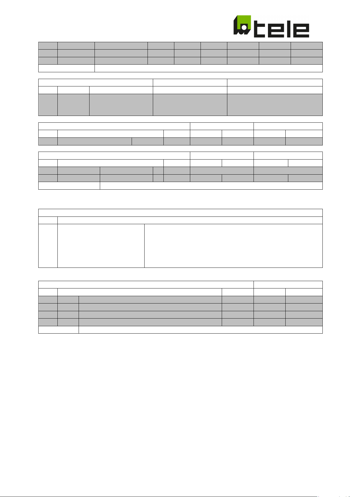
.095
PShift OFF
PShift
THR
OFF
°
7 2 20 2 20
.096
PShift ON
PShift
THR
ON
°
5 2 20 2 20
Comment:
Fixed window length 100ms
ID
Default
.099
Contact
n.c. (normally closed)
n.o. (normally opened)
n.o. (normally opened)
Turn on Delay
Conformity Range
Possible Range
ID Default
Min
Max
Min
Max
.102
Ton delay s 60 0 600 0 600
Random Turn on delay
Conformity Range
Possible Range
ID Default
Min
Max
Min
Max
.103
Ton random
Enable function
off
on … off
on … off
.104
Ton random
Turn on time
s
60
600
60
600
Comment:
The random time value is shown in .104 and cannot be edited
Device Information
ID
.105
ID: xxxxxx
xxxxx = Device ID
b: Version of the Configuration set
Password
ID Default
Min
Max
.106
PW1
1st digit of Password
0 0 9
.107
PW2
2nd digit of Password
0 0 9
.108
PW3
3rd digit of Password
0 0 9
.109
PW4
4th digit of Password
0 0 9
Remark:
If all 4 digits of the Password are 0 (default setting) the Password request is skipped
.097 PShift T Time OFF ms 0 0 300000 0 300000
Auxiliary Contact type Conformity Range Possible Range
SW: aa.dd.ccb
n.c. (normally closed)
dis. (disabled)
n.c. (normally closed)
dis. (disabled)
dd: Software version of Display Software
aa: Software version of Measuring Software
cc: Index of the Configuration set
Subject to modifications and errors Page 60 of 71 2019-06-26 edition
Page 61

3.8 Loss Of Mains detection
3.8.1 Loss Of Mains detection via voltage measurement
In this procedure, a stand-alone grid is detected with the help of 3-phase voltage monitoring.
3.8.2 Loss Of Mains detection via RoCoF
In this procedure, a stand-alone grid is detected with the help of rate-of-change of frequency. This
measurement is based on frequency measurements and triggers in the event of lasting frequency changes
over multiple periods. The df/dt limit value is given and set in Hz/s.
3.8.3 Loss Of Mains detection via vector shift
In this procedure, a phase or vector shift is detected through time measurements of the half-waves and the
comparison with previous measurements. A vector shift can occur during a sudden load change. The
threshold value is given and set in degrees.
3.9 Test function
The test function can be activated in two different ways:
• Pressing the ESC key in any window of menu level 1
• Pressing the ENT key in screen 1.050
Both output relays A and B are switched off at activation of the test function and the turn-on time begins to
run.
As with every turn-off, the turn-off time is determined. The last turn-off time can be read on screen 1.40
(Toff).
3.10 Digital inputs
Digital inputs 1 and 2 serve as feedback contacts of both isolating contactors A and B. They are driven via
the auxiliary contact of the isolation contactor. Here, the auxiliary contact can be connected as normally
opened or normally closed and the digital inputs configured accordingly in the device.
Digital input 3 serves for the remote shutdown.
Both digital inputs 4 and 5 are used for parameter switching for Italian standard IEC 0-21.
3.11 Output contacts
Both output relays R1 and R2 control the isolation contactors/section switch.
Output relay R3 switches on in case of error (if configured accordingly).
3.12 Error
Current errors are displayed in level "1.060 Error," the display of the error memory is located in level 2. The
2 error types below are differentiated.
Subject to modifications and errors Page 61 of 71 2019-06-26 edition
Page 62
1.060 Error
ENT ->
1.060 Error
ENT ->
2.0nn Error
t: 9999d 15h 03m 01s
3.12.1 Measurement error
M: UΔ UY Ū f Δf ΔΦ C
S: T0123456789ABCDEF
Only the currently present error is shown here!
Error types:
UΔ Phase to phase voltage error (under or overvoltage)
UY Phase-to-neutral voltage error (under or overvoltage)
Ū 10 minute average voltage error
f Frequency error (under or over frequency)
Δf Frequency ramp error (RoCoF)
ΔΦ Phase shift error (PShift)
C Feedback contact error
3.12.2 System error
M: UΔ UY Ū f Δf ΔΦ C
S: T0123456789ABCDEF
Error types:
T Remote shutdown active
0-9, A-F If this error appears permanently, please contact our technical support.
System error entries are found in the error memory when the unit is delivered. These occur during the final
testing of the device, in which these errors are induced on purpose. As the error memory cannot be deleted,
these entries do not represent a device error and can simply be ignored.
3.12.3 Error memory (LOG)
The error memory is displayed in level 2.
In the error memory, the occurrence, as well as the disappearance of each error, is saved with a time stamp.
Entry without an error code is therefore not a malfunction.
M: UΔ UY Ū f Δf ΔΦ C
S: T0123456789ABCDEF
nn … Number of the entry in the error memory
t … Timestamp: duration since occurrence in days/hours/minutes/seconds
Subject to modifications and errors Page 62 of 71 2019-06-26 edition
Page 63
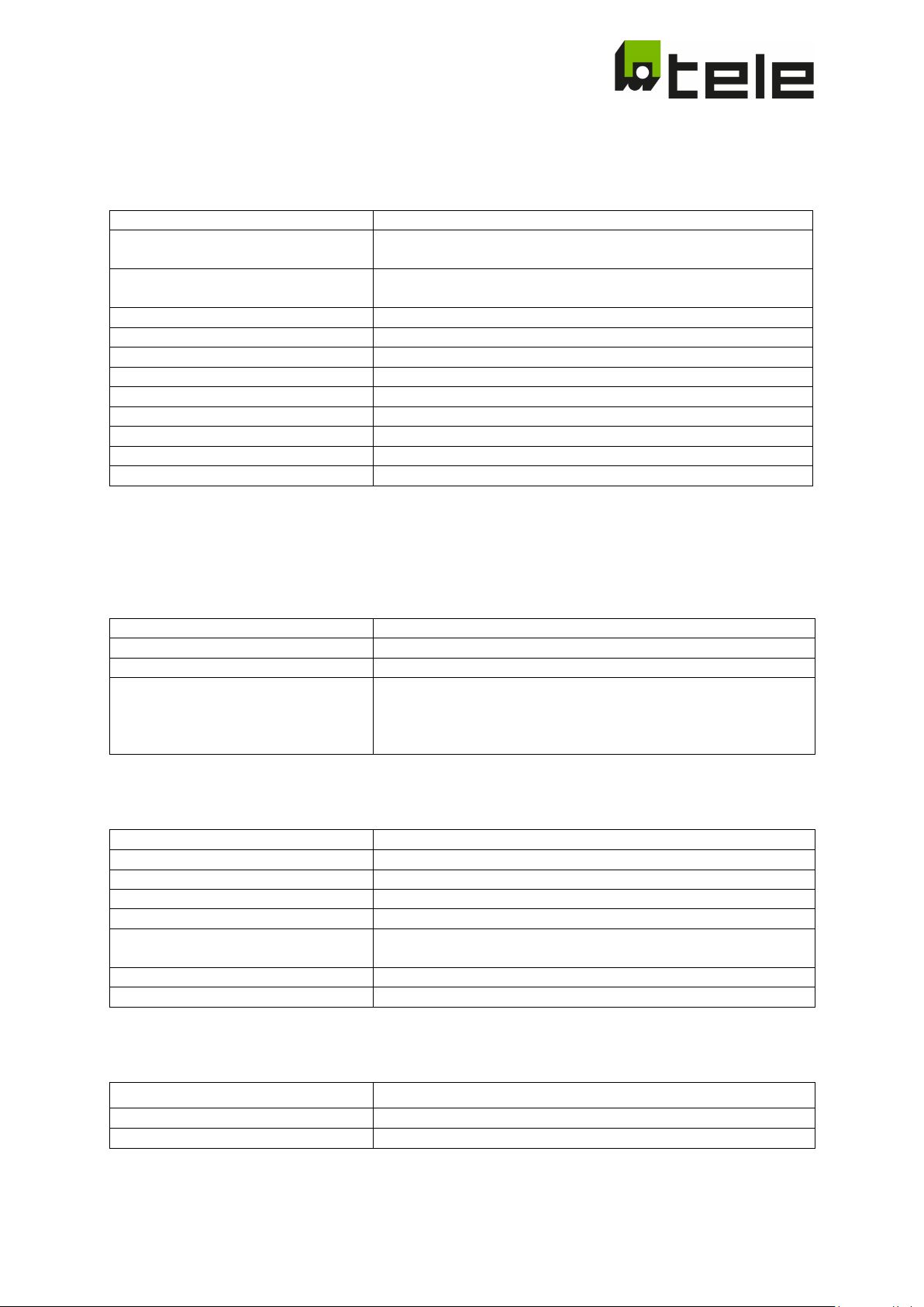
Supply voltage
DC: 24V
Tolerance of the supply voltage
DC: ± 10%
Nominal consumption
max. 1,25W / 4VA @ 230V AC
Nominal frequency
50 / 60Hz
Tolerance of the nominal frequency
48 - 63Hz
Recovery time
6 seconds + set turn-on delay
Drop-out voltage
7V
Overvoltage category
III
Internal fusing
250V / 500mA slow blow
Measuring input
3x 400V AC
Input impedance
1MΩ
Measured quantities
Phase to phase voltage, phase-to-neutral voltage,
Phase voltage
0 - 560VAC
Phase-to-neutral voltage
0 - 325VAC
RoCoF
100mHz/s - 2.000mHz/s
PShift
1 - 15°
Overload capacity
Permanent 1,4 x U
Impulse 1,6 x U
Nom
(1 second)
Overvoltage category
III
Terminals
┴
Contact type
potential-free
Switching capacity
24V DC / 5mA
4 Technical data
4.1 Supply circuit
Terminals A1 (L or +); A2 (N or -)
AC: 110 - 230V
AC: ± 30%
Duration of operation 100%
Rated surge voltage 6 kV
To ensure the device's functionality during a power failure, the device is to be supplied via an external UPS
system!
4.2 Measuring circuit
Terminals L1-L2-L3-N
10 minutes voltage average, frequency,
frequency change (RoCoF),
Phase shift (PShift)
4.3 Measuring ranges
Frequency 40 - 65Hz
Rated surge voltage 4 kV
Nom
4.4 Digital inputs
Subject to modifications and errors Page 63 of 71 2019-06-26 edition
I1 and ┴ ; I2 and ┴ ; I3 and ┴ ; I4 resp. I5 and
Page 64
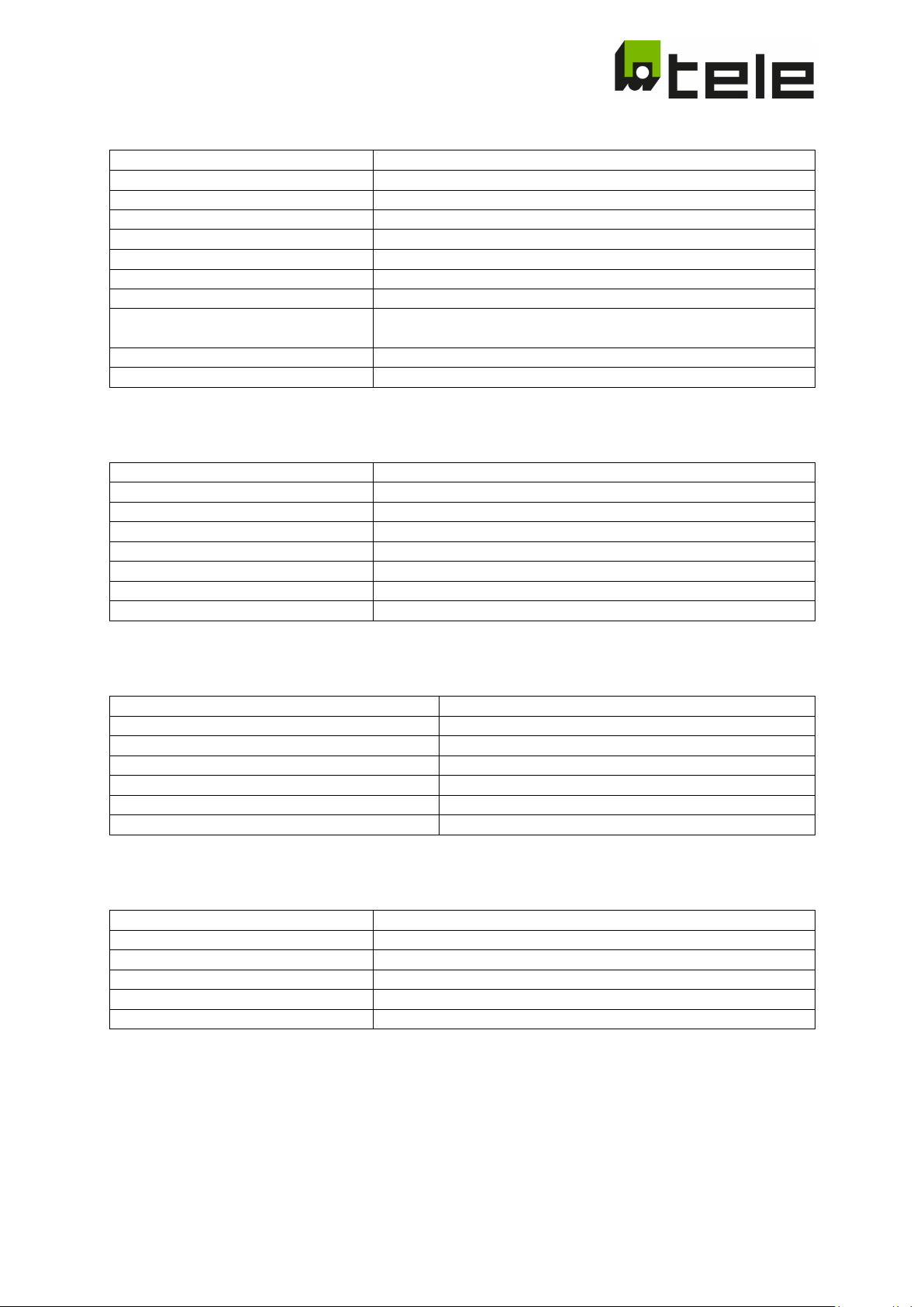
Terminals
11-12-14; 21-22-24; 31-32-34
Number and type of contacts
3 changeover contacts
Switching capacity
5A / 250V AC
Electrical switching frequency (AC1-)
100 x 103 switching cycles
Mechanical switching frequency
15 x 106 switching cycles
Short time value (1s)
5A
Withstanding voltage across open
contacts
Relay contacts: 1000V
Terminals: 450V
rms
Overvoltage category
III
Rated surge voltage
4 kV
Voltage measurement:
Base accuracy
< 0,5% @ +25°C
Temperature effect
< 0,01%/°C
Resolution
10mV
Frequency measurement:
Base accuracy
< 0,01Hz @ +25°C
Temperature effect
< 0,0002Hz/°C
Resolution
1mHz
Rated insulation voltage
400V
Supply circuit/measuring circuit
Safe isolation
Supply circuit/output circuit
Safe isolation
Supply circuit / digital inputs
Safe isolation
Output circuit / digital inputs
Base isolation
Ambient temperature operation
-25 up to +55°C
Display capability
-15 up to +55°C
Relative air humidity
5 up to 95%
Degree of contamination
2
4.5 Output circuit
Contact material AgNi
Continuous current value 5A
4.6 Accuracy
rms
4.7 Insulation data
Insulation
Output circuit/measuring circuit Base isolation
4.8 Environmental conditions
Ambient temperature storage -40 up to +70°C
Weight 300g
Subject to modifications and errors Page 64 of 71 2019-06-26 edition
Page 65
Connection cross-section
max. 2,5mm2
Stripping length
max. 8mm
Measuring inputs
max. 750V/16A
Tightening torque
max. 0,5Nm
Digital input circuits and output relays
No limitation for simultaneous operation of inputs and/or
Wire diameter
Ø max. 0,8mm
Terminals
IP 20
Housing
IP 20
4.9 Electrical connection
Electrical capacity:
Relay outputs / digital inputs
Screw M3, screwdriver for slotted screws 0,6 x 3,5mm
max. 450V/16A
outputs within the specified limits
4.10 Sealing wire
4.11 Protection class
Subject to modifications and errors Page 65 of 71 2019-06-26 edition
Page 66

5 Operation and commissioning
5.1 Initial commissioning
The device is delivered without a pre-configured standard. During initial commissioning, the device will
prompt to select a standard (level 5 - menu point 5.001). Here, the corresponding configuration/standard
must be selected via +/- and confirmed with ENTER.
You can find more information in the menu structure.
5.2 Menu navigation
The display unit consists of a 4-line text display with 20 characters per line.
The display has 5 levels. The different displays of the levels can be navigated via + and -.
5.2.1 Level 0
Start screen (display for 5 seconds at power-up)
Basic information is displayed here. This display appears after power-up and remains visible for 5 s. Then
the display jumps to the first window in level 1.
5.2.2 Level 1
Measurements (screen 1.010-1.032)
Display of the current measurements.
Additionally, it will also be displayed here if the parameter set corresponds to the default configuration (dflt
- default = base or factory setting), was edited within the normative permissible limit values (edit – edited),
or is set outside the normative permissible limit values (ncnf – non conform = does not comply with the
selected regulation or the selected standard).
If required, display of time-lapse "reconnection timer" (turn-on time) in seconds.
Navigation +/-. From this screen, you can access level 3 via ENT
Digital inputs and turn-off time (screen 1.040)
Display of the last turn-off time (Toff) of the connected contactors (the larger value for two-channel
systems).
Additionally, it will also be displayed here if the parameter set corresponds to the default configuration (dflt
- default = base or factory setting), was edited within the normative permissible limit values (edit – edited),
or is set outside the normative permissible limit values (ncnf – non conform = does not comply with the
selected regulation or the selected standard).
If required, display of time-lapse "reconnection timer" (turn-on time) in seconds.
Status display of the 5 digital inputs.
Navigation +/-. From this screen, you can access level 3 via ENT.
Test/Reset (1.050)
A relay test is triggered by pressing the ENT key. In this test, relays A and B turn off and the "reconnectiontimer" (turn-on time) begins to run.
In addition, a reset event can be carried out with the test/rest function, which allows relay 1/2 to be switched
on again after a contact error (C) (required for the three parameter sets VDE-AR-N 4105). The test/reset
event can also be performed by pressing the ESC key in level 1.
Subject to modifications and errors Page 66 of 71 2019-06-26 edition
Page 67

Error (1.060)
Display of current error:
M Measurement error
S System error
Navigation +/-. You can access level 2 by pressing the ENT key.
5.2.3 Level 2
Error memory
This is where the latest errors are displayed with a time stamp (time since occurrence).
Both positive, as well as negative error flanks, are saved and displayed.
Navigation +/-. From this screen, you can access level 1 via ESC.
5.2.4 Level 3
Parameter display
Here, the parameters that have been visibly switched for the corresponding configuration are displayed.
Navigation +/-. From this screen, you can access level 1 via ESC.
You can access the editing mode of the selected parameter via PROG (can be lead-sealed).
The password query is skipped if the password is "0000" and you will end up directly in editing mode in level
5.
If a valid password has been entered in the last 60 seconds, the password query is skipped and you will end
up directly in level 5.
If a password other than "0000" has been defined, you will be asked for the password in level 4.
5.2.5 Level 4
Password input
The currently active digit of the password can be incremented/decremented (0…9) via +/-.
ENT jumps to the next digit of the password entry.
The entered password is checked after pressing ENT at the 4th position.
ESC jumps back to the previous digit of the password entry.
The program goes back to Level 3 when you press ESC at the first digit of the password.
If you have forgotten the password, please contact our technical support and let them know the device ID.
You will receive a master password only relevant for your device.
5.2.6 Level 5
Parameter editing
In this level, the parameter previously selected in level 3 can be changed with +/-.
Confirm with ENT or use ESC to discard the change. In both cases, the display jumps to the corresponding
parameter in level 3.
Additionally, it will also be displayed here whether the value that was just edited corresponds to the default
configuration (dflt - default = base or factory setting), if it was edited within the normative permissible limit
values (edit – edited) or is set outside the normative permissible limit values (ncnf – non conform = does not
comply with the selected regulation or the selected standard).
Alongside thresholds, times, and modes, the 4 digits of the password also have 1 parameter each.
Subject to modifications and errors Page 67 of 71 2019-06-26 edition
Page 68

The current standard is a parameter too. This means that a newly selected standard will be activated by
changing this parameter. Therefore all previous changes will be discarded.
If the already set standard is selected, the standard will be reset to default.
Subject to modifications and errors Page 68 of 71 2019-06-26 edition
Page 69
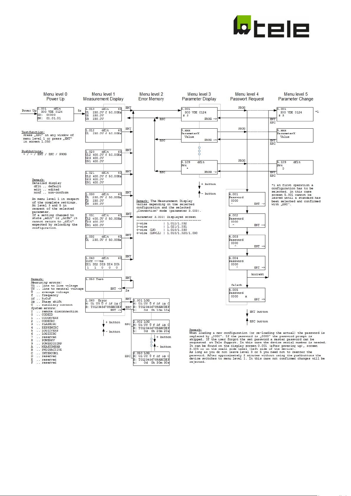
5.3 Menu structure
Subject to modifications and errors Page 69 of 71 2019-06-26 edition
Page 70
5.4 Applicable rules and standards
Functional
No. Standard Regions 1 channel
100 CEI 0-21 Italy X
safety
(2 channel)
selectable
1 or 2
channel
200 VDE V 0126-1-1
305
306
307
706
410
460
510
VDE-AR-N 4105
(Pn ≤ 50kW)
VDE-AR-N 4105
(Pn > 50kW)
VDE-AR-N 4105
(inverter)
VDE-AR-N 4110
(Pn > 135kW)
G99/1 LV
Amendment 3
G99/1 HV
Amendment 3
G98/1
Amendment 2
Turkey, Belgium, France,
Greece, …
Germany (low voltage) X
Germany (low voltage) X
Germany (low voltage) X
Germany (medium voltage) X
Great Britain (low voltage) X
Great Britain (medium/high
voltage)
Great Britain (medium/high
voltage)
X
X
X
600 C10-11 LV Belgium (low voltage) X
650 C10-11 MV Belgium (medium voltage) X
800 OENorm E 8001-4-712 Austria X
900 EN 50438 Europe X
950 EN 50438 (DK) Denmark X
1000 NRS 097-2-1: 2017 South Africa X
9003 OPEN SETUP Freely configurable setup X
Subject to modifications and errors Page 70 of 71 2019-06-26 edition
Page 71

CALL US
ONLINE
SUPPORT
WEB
+43 / 1 614 74 - 0
www.tele-online.com
5.5 Lead seal
After commissioning, the device is to be secured against unauthorized changes of the protection-relevant
setting parameters via a configurable password! If password protection is not used or if the country-specific
regulations or standards demand it, the device is to be lead-sealed!
For further information please contact:
TELE Haase Steuergeraete Ges.m.b.H.
Vorarlberger Allee 38
1230 Vienna
Austria
Subject to modifications and errors Page 71 of 71 2019-06-26 edition
 Loading...