

Page 1

Instructions
WFM61UP FP, WFM70UP FP, and WFM71UP FP
Front Panel Upgrade
WFM6100, WFM7000, and WFM7100
Waveform Monitors
075-0948-00
Warning
The servicing instructions are for use by qualified
personnel only. To avoid personal injury, do not
perform any servicing unless you are qualified to
do so. Refer to all safety summaries prior to
performing service.
www.tektronix.com
*P075094800*
075094800
Page 2

Copyright © Tektronix. All rights reserved. Licensed software products are owned by Tektronix or its subsidiaries or
suppliers, and are protected by national copyright laws and international treaty provisions.
Tektronix products are covered by U.S. and foreign patents, issued and pending. Information in this publication supercedes
that in all previously published material. Specifications and price change privileges reserved.
TEKTRONIX and TEK are registered trademarks of Tektronix, Inc.
Contacting Tektronix
Tektronix, Inc.
14200 SW Karl Braun Drive
P.O. Box 500
Beaverton, OR 97077
USA
For product information, sales, service, and technical support:
H In North America, call 1-800-833-9200.
H Worldwide, visit www.tektronix.com to find contacts in your area.
Page 3

Service Safety Summary
Only qualified personnel should perform service procedures. Read this Service
Safety Summary before performing any service procedures.
Do Not Service Alone. Do not perform internal service or adjustments of this
product unless another person capable of rendering first aid and resuscitation is
present.
Disconnect Power. To avoid electric shock, switch off the instrument power, then
disconnect the power cord from the mains power.
Use Care When Servicing With Power On. Dangerous voltages or currents may
exist in this product. Disconnect power, remove battery (if applicable), and
disconnect test leads before removing protective panels, soldering, or replacing
components.
To avoid electric shock, do not touch exposed connections.
WFM61UP FP, WFM70UP FP, and WFM71UP
1
Page 4

Service Safety Summary
2
WFM61UP FP, WFM70UP FP, and WFM71UP
Page 5
Kit Description
This document describes replacing the waveform monitor front panel with the
new, upgraded front panel. One very obvious change is the number of buttons on
the front panel; there are many more buttons on the new front panel. This is
necessary because the new front panel does not employ a touch-screen interface;
all control is through the front panel buttons. Among other things, this change
provides a noticeable improvement in instrument front panel response.
Products
WFM6100 All
WFM7000 All
WFM7100 All
Minimum Tool and Equipment List
Required tools and equipment Part number
PC with USB port -- -- -- -- -- -- -- -- -- --
Kit Parts List
Network connection ------ -- -- ------ -- --
Torque screwdriver handle Standard tool
T-10 TORX bit Standard tool
Quantity Part number Description
1Each 614--1044--xx FRONT PANEL ASSY
1 Each 063--4072--xx USB FLASH DRIVE, PROGRAMMED
1Each NS OPTION KEY LABEL
1 Each 075--0948--00 UPGRADE KIT INSTRUCTIONS (THIS DOCUMENT)
1Each NS IMPORTANT DOCUMENTS ENVELOPE
1Each 071-2191-01 MANUAL, TECH; SVCPT--UPG; TEKTRONIX SUPPLE-
MENTAL INFORMATION SHEET FOR THE PEOPLES
REPUBLIC OF CHINA; CHINA ROHS
NS - Not Saleable
WFM61UP FP, WFM70UP FP, and WFM71UP
3
Page 6

Kit Description
4
WFM61UP FP, WFM70UP FP, and WFM71UP
Page 7

Installation Instructions
These instructions are for personnel who are familiar with servicing the product.
If you need further details for disassembling or reassembling the product, refer to
the appropriate product manual. Contact your nearest Tektronix, Inc., Service
Center or Tektronix Factory Service for installation assistance.
CAUTION. To pr event static discharge damage, service the product only in a
static-free environment. Observe standard handling precautions for static-sensitive devices while installing this kit. Always wear a grounded wrist strap,
grounded foot strap, and static resistant apparel while installing this kit.
These instructions will guide you through the following steps:
H Update the software
H Connect the waveform monitor to the network, if not already connected
H Obtain the waveform monitor IP address
H Verify the network connection
H Obtain the waveform monitor software version
H Update the software
H Replace the front panel
H Remove the top cover
H Remove the fan bracket (optional)
H Remove the front panel/LCD assembly
H Install the new front panel/LCD assembly
H Replace the fan bracket
H Replace the top cover
H Apply the instrument model label
H Verify Operation
H Check waveform monitor IP address; it may have changed
H Update the Installed Options
WFM61UP FP, WFM70UP FP, and WFM71UP
5
Page 8

Installation Instructions
Update the Software
Before installing the new front panel assembly, you must first update the
instrument software, located on the USB Flash Drive included in this kit.
These instructions are written for a PC running Windows XP.
NOTE. If a notebook computer is used, make sure it has a full battery charge or
is connected to an AC power source.
If the PC and the waveform monitor are already network connected, go to
Obtain waveform monitor IP address,onpage7.
NOTE. Do not reboot the instrument after updating the software. Disconnect the
power cord and proceed with the front panel replacement.
Network Connection and
IP Settings
To allow network access to the instrument, you need to set the IP address.
Network addresses can be assigned either automatically or manually. If your
network does not use DHCP, you will have to manually enter the address for the
instrument. To get an address, talk to your LAN administrator.
1. Verify that the waveform monitor is connected to the network.
2. Power on the waveform monitor.
3. Press the MAIN button to display the Main menu, and then touch the
Config soft key to display the Configuration submenu.
4. Touch the Utilities soft key, and then the Communications soft key.
5. Touch the Config Mode soft key, and then set the Config Mode to Manual
or DHCP, depending on your network setup.
Selecting the configuration mode will close the Config Mode submenu.
6. Touch the Network Setup soft key.
a. Select Enabled under Remote Control Port.
b. Select Enabled under Remote W eb Interface.
7. If you can’t use DHCP you will have to set the IP Address, subnet mask, and
gateway address network parameters in the Network setup menu; see your
LAN administrator for the required values. (Be sure to use compatible
addresses between the PC and the monitor.)
8. Press the Close soft keys to close the submenus.
6
WFM61UP FP, WFM70UP FP, and WFM71UP
Page 9

Installation Instructions
Obtain waveform monitor
IP address
Verify the network
connection
These steps assume the instrument has already been configured for network
connection as described previously, and guided by a network administrator.
1. Press the MAIN button, then touch the Config softkey.
2. Touch the Utilities, then the Communications, and the Network Setup
softkeys.
3. Make a note of the waveform monitor’s IP address. You will need that in the
next procedure.
NOTE. If you are using DHCP and the waveform monitor did not receive an IP
address, go back through steps 3 through 5 of the Network Connection and IP
Settings procedure, change the waveform monitor to Manual, and then change it
back to DHCP.
If the waveform monitor still does not receive an IP address, cycle the power
while in DHCP mode.
4. Touch OK to close the network setup window.
1. On the PC, select Start > All Programs > Accessories > Command
Prompt.
2. Change to drive C:\ by typing cd c:\ in the command window, and then press
the Enter key.
3. In the command window, type ping, followed by the waveform monitor’s IP
address, and then press the Enter key. For example: ping 192.168.1.2.
4. Check that the replies that appear on the PC resemble the following:
Pinging 192.168.1.2 with 32 bytes of data:
Reply from 192.168.1.2: bytes=32 time=2ms TTL=63
Reply from 192.168.1.2: bytes=32 time=1ms TTL=63
Reply from 192.168.1.2: bytes=32 time=1ms TTL=63
Reply from 192.168.1.2: bytes=32 time=1ms TTL=63
Ping statistics for 192.168.1.2:
Packets: Sent = 4, Received = 4, Lost = 0 (0% loss),
Approximate round trip times in milli-seconds:
Minimum = 1ms, Maximum = 2ms, Average = 1ms
If there are no replies, check your network connections and verify that the
waveform monitor settings and PC settings are correct.
WFM61UP FP, WFM70UP FP, and WFM71UP
7
Page 10

Installation Instructions
Update the software
In this procedure, you load the Upgrade Assistant file into the PC, check the
waveform monitor software version, and run the Upgrade Assistant.
1. Find the plastic bag in the upgrade kit that contains the USB Flash Drive and
the Option Key label, and plug the Flash Drive into a USB port on the PC.
2. Create a folder on your PC. Name the folder something easy to remember,
like “c:\wfmupgrade”.
3. Copy the file WfmUpgrade.exe from the USB Flash Drive into the directory
created in step 2.
CAUTION. DO NOT just unplug the USB Flash Drive from the PC. This can
erase the files and/or damage the USB Flash Drive.
4. Unmount the USB Flash Drive, using one of the following methods:
H You can use the Safely remove hardware icon, on the taskbar:
Left-click the icon and select the Safely remove USB Mass Storage
Device -- Drive (x) button that appears. Wait until the Safe To Remove
Hardware message appears before removing the USB Flash Drive from
the USB port.
H Or, you can open My Computer, right-click on the drive with the USB
Flash Drive, and select Eject. Wait for the light to go out on the Flash
Drive before removing it from the USB port.
5. On the waveform monitor, press the MAIN button, then touch the Config
--Utilities andthentheView Hw/Sw Version softkeys. Make a note of the
software version (1.1, 1.23, or 1.25).
6. Touch OK to close the HW/SW version display.
NOTE. You will need to identify whether your software is Version 1.1 or if it’s a
later version, in step 12.
7. Plug the same USB Flash Drive, included in the upgrade kit, into the
waveform monitor USB port.
8. On the PC, select Start > All Programs > Accessories > Command
Prompt to open the Command Prompt window.
9. On the PC, change the directory to the directory created in step 2. For
example, type cd c:\wfmupgrade in the Command Prompt window and
press the Enter key to change to the c:\wfmupgrade directory.
8
WFM61UP FP, WFM70UP FP, and WFM71UP
Page 11

Installation Instructions
10. Type WfmUpgrade in the Command Prompt window and press the Enter
key.
11. The upgrade assistant will respond with:
######################################################
# Copyright (C) 2007 Tektronix, Inc.
#
# Before executing, confirm your existing software version as
follows:
# 1) Connect network cable
# 2) Boot the instrument
# 3) Press MAIN, then navigate to Config -> Utilities -> View HW/SW
Version
# 4) Note your existing software version number
#5)PressOK
# 6) Insert the USB memory device
# 7) Press MAIN, then wait for USB Mount/UnMount selection to
read ”Unmount”
######################################################
Is your WFM Software version V1.1 ? :(y/n)
12. Type a y if your software version is V1.1, or an n if your software version is
V1.23 or 1.25, and then press the Enter key. The upgrade assistant will
respond with either:
->V1.1 Upgrade
or
->V1.23/V1.25 Upgrade
Please Enter IP address xxx.xxx.xxx.xxx :
13. Enter the waveform monitor’s IP address and then press the Enter key. The
assistant window will close, and the waveform monitor upgrade will begin.
NOTE. This process will take approximately 15 minutes.
CAUTION. DO NOT remove the USB Flash Drive from the waveform monitor
until the instrument says it’s safe to do so. Removing the USB Flash Drive too
soon can erase the files and/or damage the USB Flash Drive.
WFM61UP FP, WFM70UP FP, and WFM71UP
9
Page 12

Installation Instructions
Replace the Front Panel
14. When the waveform monitor screen indicates the update has completed
successfully, disconnect the power cord from the waveform monitor.
NOTE. Do not reconnect power to the waveform monitor until after the front
panel replacement, described below, is complete.
WARNING. To avoid electric shock, switch off the instrument power, then
disconnect the power cord from the mains power. Failure to do so can cause
injury or death.
Remove portable cabinet
CAUTION. To pr event static discharge damage, service the product only in a
static-free environment. Observe standard handling precautions for static-sensitive devices while installing this kit. Always wear a grounded wrist strap,
grounded foot strap, and static resistant apparel while installing this kit.
Remove the old front panel as follows:
If the waveform monitor is installed in a WFM7F02 portable cabinet, remove it
as follows:
1. Position the instrument with the front panel down on a work surface, using a
protective pad or instrument cover to prevent front panel damage.
2. Remove the two cabinet attaching screws, shown in Figure 1.
3. Carefully slide the WFM7F02 cabinet up off of the instrument chassis and
setitaside.
10
WFM61UP FP, WFM70UP FP, and WFM71UP
Page 13
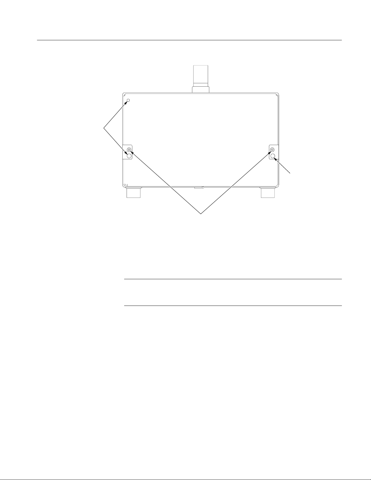
Keying pins
Installation Instructions
Keying pin
Remove top cover
Cabinet
attaching screws
Figure 1: Portable cabinet attaching screws
The top cover is a slip-lock design.
NOTE. If there is a Traceable Calibration sticker showing the last calibration
date and the due date for the next calibration on top of the front panel frame,
remove it carefully so you can reapply it after this update.
1. Remove the two T-10 screws at the top cover front corners (see Figure 2).
2. Remove the four T-10 screws securing the top cover to the rear panel (see
Figure 2).
1
3. Slide the top cover back approximately
/2inch and then lift it from the
chassis.
WFM61UP FP, WFM70UP FP, and WFM71UP
11
Page 14

Installation Instructions
Figure 2: Removing the top cover
Remove fan bracket
(optional)
Remove front panel/LCD
assembly
For better access to the connectors, the fan bracket may be removed as follows:
1. Remove the two T-10 screws that secure the fan bracket to the chassis, one
on each side.
2. Lift the fan bracket up and back, to gain access to the fan cable connector.
3. Disconnect the fan cable from J890 (see Figure 3) by depressing the latch on
the connector and pulling it up.
4. Make sure the spring clips remain attached to the bottom of the fan bracket.
Remove the front panel and LCD assembly as a unit
1. Remove the six T-10 screws that secure the front panel assembly to the
chassis, two on each side and two on the bottom.
1
2. Pull the front panel assembly forward approximately
to not stress the cables connecting the front panel to the main board.
CAUTION. Be careful of the main board extension containing the headphone and
USB connectors, until they are free of the front panel assembly. Failure to do so
may result in damage to the connectors or to the Main board.
/2inch, being careful
12
3. Disconnect the touch panel cable (orange) connected to J27 on the main
board (see Figure 3).
WFM61UP FP, WFM70UP FP, and WFM71UP
Page 15

Installation Instructions
4. Disconnect the cables connecting the front panel/LCD assembly to the main
board at J17, J18, and J29 (see Figure 3).
J890
J17
J18 J27 J29
Figure 3: Old front panel cable connections
5. Lift the front panel assembly away and set it aside.
CAUTION. Be careful of the main board extension containing the headphone and
USB connectors, until they are free of the front panel assembly. Failure to do so
may result in damage to the connectors or to the Main board.
Install new
front panel/LCD assembly
Install the new front panel as follows:
6. Unpack the new front panel, and place it near the front of the chassis.
7. Pre-form the LCD cable, to J17, as shown in Figure 4, to make installation
easier. This cable is quite stiff and can make installation difficult if it is not
pre-formed.
8. Connect the three cables from the front panel to J17, J18, and J29 on the
Main board. Make sure to dress the LCD cable to J17 as shown in Figure 4;
away from the side of the waveform monitor, and capturing the cable to J18.
WFM61UP FP, WFM70UP FP, and WFM71UP
13
Page 16

Installation Instructions
J890
J17
J18
J29
Figure 4: New front panel cable connections
NOTE. As the new front panel does not use a touch screen no connection is made
to J27.
9. Slide the front panel into the chassis, starting the bottom slightly before the
top. A tight friction fit is necessary, so this may be difficult. You might find
it helpful to prop the front of the waveform monitor up with a small book or
wooden block while doing this.
14
Replace fan bracket
10. Replace the six T-10 screws that secure the front panel assembly to the
chassis, two on each side and two on the bottom. Torque these screws to
8 in/lb.
If the fan bracket was removed, reinstall it as follows:
1. Insert the fan connector into J890 (see Figure 4). This is a latching connector, and is keyed for polarity.
2. Slide the fan bracket into place, engaging the alignment pins on the chassis
sides.
3. Press the bracket down to compress the springs, and install the two T-10
screws that secure the fan bracket to the chassis, one on each side. Torque
these screws to 8 in/lb.
WFM61UP FP, WFM70UP FP, and WFM71UP
Page 17

Installation Instructions
Replace top cover
Verify Operation
1. Place the top cover onto the instrument, making sure the cover fingers go
into the slots in the chassis, and slide it forward.
2. Replace the four T-10 screws securing the top cover to the rear panel (see
Figure 2). Torque these screws to 8 in/lb.
3. Replace the two T-10 screws at the top cover front corners (see Figure 2).
Torque these screws to 8 in/lb.
4. If you removed a Traceable Calibration sticker earlier, reapply it now in
approximately the same position.
Use this process to verify that the front panel replacement was successful.
NOTE. The first power up after this upgrade will take about five minutes. The
LCD and XGA output may be blank or random during this time. The front panel
is being programmed during this process; do not remove power to the unit.
1. Apply power to the instrument, and immediately look at the front panel. The
MAG, LINE SELECT, and CURSOR buttons should be lit. The other
front-panel buttons will light one at a time, in sequence. Verify that all
buttons do light.
Troubleshooting
2. After the Boot Loader process, the Power on diagnostic page should appear.
Verify that all self tests pass. Any failures will be shown in red.
3. After the diagnostics have completed, the instrument state will be restored.
If the waveform monitor does not power up correctly during the Verify Operation
procedure, check the connections at both ends of the front panel cables. Table 1
shows the most common problems and the associated cable to check. Refer to
Figure 4 for cable locations.
Table 1: Common upgrade cable problems
Problem Check cable
White screen LCD cable, to J17
Black screen Backlight cable, to J18
Buttons do not light or do not work Front panel cable, to J29
WFM61UP FP, WFM70UP FP, and WFM71UP
15
Page 18

Installation Instructions
Update Installed Options
This procedure enables any additional options received with the update. The new
option key is on a printed document included in the kit.
1. Make sure the waveform monitor and the PC are both connected to the
2. Press the Config button and use the arrow keys or the General knob to
3. If Web Enable is Off use the arrow keys to set it to On.
4. While the Network Settings menu is available, check the waveform
5. On the PC, launch a Web browser and type http:// in the address field,
network, as they were for the software upgrade.
navigate to the Network Settings selection.
monitor’s IP address. If using DHCP, the network might have assigned a
new IP address.
followed by the waveform monitor IP address. For example,
http://192.168.1.2.
Read the Manual
6. The instrument Web page should appear. If it doesn’t, check the network
connections and the settings on the waveform monitor and the PC.
7. On the displayed Web page, click Instrument Options to show the
waveform monitor’s installed options.
8. Remove the option key label from the plastic bag that contained the USB
Flash drive, and enter the new option key in the Key box. Enter the string
exactly as printed, without leading or trailing spaces.
9. Click Submit. A pop-up with the message “Instrument Options Updated
Successfully” should appear. If the options are not updated, reenter the
option key string.
10. Peel the backing from the option key label and paste it over the old option
key label on the side of the waveform monitor. Along with the new option
key, this label notes that Option FP has been installed and enabled in the
instrument.
Operating your WFM6100, WFM7000, or WFM7100 waveform monitor will be
somewhat different with this new front panel and software. Make sure to read the
new Quick Start User manual for information on how to operate the instrument.
The new Quick Start User manual can be found in the Documentation folder on
the USB Flash Drive included in the kit.
16
g End of document g
WFM61UP FP, WFM70UP FP, and WFM71UP
 Loading...