


xx
WFM5200 Series
Waveform Monitors
ZZZ
System Integration
Technical Reference
*P077054801*
077-0548-01


xx
WFM5200 Series
Waveform Monitors
ZZZ
System Integration
Technical Reference
Warning
The service instructions are f
To avoid personal injury, do not perform any servicing unless
you are qualified to do so. Refe
to performing service.
www.tektronix.com
077-0548-01
or use by qualified personnel only.
r to all safety summaries prior

Copyright © Tektronix. All rights reserved. Licensed software products are owned by Tektronix or its subsidiaries
or suppliers, and are protected by national copyright laws and international treaty provisions.
Tektronix products are covered by U.S. and foreign patents, issued and pending. Information in this publication
supersedes that in all previously published material. Specifications and price change privileges reserved.
TEKTRONIX and TEK are registered trademarks of Tektronix, Inc.
Contacting Tektronix
Tektronix, Inc.
14150 SW Karl Braun Drive
P.O . B ox 50 0
Beaverto
USA
For product information, sales, service, and technical support:
n, OR 97077
In North America, call 1-800-833-9200.
World wide , visit www.tektronix.com to find contacts in your area.

Table of Contents
General safety summary .............. ................................ ................................ ............. ii
Preface ............................................................................................................... v
Where to find more information............... ................................ ............................... v
Physical, e
Rack and custom installation ............................... ................................ ....................... 3
Instrument connectors.............................................................................................. 5
Video system installation ....... ................................ ................................ .................. 16
Power-on and power-off procedure.............................................................................. 20
Network operation......................................... .................................. ...................... 22
nvironmental, and power specifications...... ................................ ....................... 1
WFM5200 Series System Integrator i

General safety summary
General safet
To avoid fir
e or personal
injury
ysummary
Review the fo
this product or any products connected to it.
To avoid pot
Only qualified personnel should perform service procedures.
Use proper
certified for the country of use.
Ground th
of the power cord. To avoid electric shock, the grounding conductor must be
connected to earth ground. Before making connections to the input or output
terminals of the product, ensure that the product is properly grounded.
Observe all terminal ratings. To avo i d fire or shock hazard, observe all ratings
and markings on the product. Consult the product manual for further ratings
information before making connections to the product.
Do not apply a potential to any terminal, including the common terminal, that
exceeds the maximum rating of that terminal.
llowing safety precautions to avoid injury and prevent damage to
ential hazards, use this product only as specified.
power cord. Use only the power cord specified for this product and
eproduct.This product is grounded through the grounding conductor
Power disconnect. The power cord disconnects the product from the power source.
Donotblockthepowercord;itmustremain accessible to the user at all times.
Do not operate without covers. Do not operate this product with covers or panels
removed.
Do not operate with suspected failures. If you suspect that there is damage to this
product, have it inspected by qualified service personnel.
Avoid exposed circuitry. Do not touch exposed connections and components when
power is present.
Use proper AC adapter. Use only the AC adapter specified for this product.
Do not operate in wet/damp conditions.
Do not operate in an explosive atmosphere.
Keep product surfaces clean and dry.
Provide proper ventilation. Refer to the manual's installation instructions for details
on installing the product so it has proper ventilation.
ii WFM5200 Series System Integrator

General safety summary
Terms in this manual
Symbols a nd terms on the
product
These terms may
appear in this manual:
WAR N ING. Warning statements identify conditions or practices that could result
in injury or loss of life.
CAUTION. Caution statements identify conditions or practices that could result in
damage to this product or other property.
These terms may appear on the product:
DANGER in
dicates an injury hazard immediately accessible as you read
the marking.
WAR N IN G
indicates an injury hazard not immediately accessible as you
read the marking.
CAUTIO
N indicates a hazard to property including the product.
The following symbol(s) may appear on the product:
WFM5200 Series System Integrator iii

General safety summary
iv WFM5200 Series System Integrator

Preface
Preface
Where t
This documen
systems for high definition multimedia interface (HDMI) formats and
high-definition (HD), standard-definition (SD), and 3 Gb/s SDI digital video
content where the Tektronix WFM5200 and WFM5250 Waveform Monitors
will be deployed.
This manual is divided into the following sections:
Physical, environmental, and power specifications (See page 1.)
Rack and custom installation (See page 3.)
Instrum
System installation (See page 16.)
Network operation (See page 22.)
o find more information
The following tables list the documentation that is available for the product and
shows where you can find it: in a printed manual, on the product documentation
OM, or on the Tektronix Web site.
CD-R
t provides information for system integrators who are designing
ent connectors (See page 5.)
Table i: Product documentation
Item Purpose Location
Installation and Safety Instructions Provides safety and compliance information along
with hardware installation instructions to present the
associated safety warnings. This manual is available in
English, Japanese, Russian, and Simplified Chinese.
User Manual
Online H elp
Specifications and Performance
Verification Technical Reference
Release Notes
Service Manual Provides information about adjustments, repair, and
Provides operation and application information.
In-depth instrument operation and UI help.
Specifications and procedures for checking instrument
performance.
Software release information about new features and
existing issues.
replaceable parts.
Printed m anual and also
available in electronic format
at www.tektronix.com/downloads
Product Documentation
CD and available at
www.tektronix.com/downloads
On the instrument
Product Documentation
CD and available at
www.tektronix.com/downloads
Available at
www.tektronix.com/downloads
Available at
www.tektronix.com/downloads
WFM5200 Series System Integrator v

Preface
Table ii: Relat
Item Purpose Location
Top 10 Application-Based Presets
Preventing Illegal Colors
(application note)
Understand
(poster)
A Guide to Standard and
High Defini
Measurements (primer)
Analog an
Monitoring (application note)
Audio Monitoring (application note)
ring Surround Sound Audio
Monito
(application note)
NTSC V
(primer)
PAL Systems Television
Measurements (primer)
ed reference documents
ing Colors and Gamut
tion Digital Video
d Digital Audio
ideo Measurements
Describes use
Describes ho
displays can be used to help prevent the undesired
impact of color gamut violations and to simplify the
assessment o
Provides a l
Arrowhead, and Lightning displays can be used to help
prevent the undesired impact of color gamut violations.
This book explains the basics of making standard and
high-defin
Describe
signals. Also discussed are specific differences in the
methods used to monitor analog audio versus digital
audio, a
analog audio to monitoring digital audio.
Describ
and explains the physical and electrical characteristics
and the specific strength and weaknesses of the
ent digital audio signal formats.
differ
Descri
audio and tells how to use the Surround Sound display
to visualize key audio-level and phase relationships
s audio format.
in thi
This b
measurements.
This book explains the basics of making PAL video
measurements.
ful presets and how to set them up.
w the Diamond, Arrowhead, and Lightning
f proper gamut compliance.
arge visual display of how the Diamond,
ition, digital-video measurements.
s how to monitor analog and digital audio
nd how to plan the transition from monitoring
es balanced and unbalanced audio signals,
bes the basics of 5.1-channel surround sound
ook explains the basics of making NTSC video
Product Documentation
CD and availab
www.tektronix.com/downloads
Product Docu
CD and available at
www.tektronix.com/downloads
Available at
www.tektro
Product Documentation
CD and available at
www.tektr
Availabl
www.tektronix.com/downloads
Availab
www.tektronix.com/downloads
Available at
www.te
Product Documentation
CD and
www.tektronix.com/downloads
uct Documentation
Prod
CD and available at
www.tektronix.com/downloads
le at
mentation
nix.com/downloads
onix.com/downloads
eat
le at
ktronix.com/downloads
available at
Table iii: Graphics and photos for system integrators
Item Purpose Location
Front and rear panel photos of the
WFM5200 and WFM5250
Front and rear panel line art
These photos might be useful if you need to present information
to your customer
This line art might be useful if you need to present information
to your customer
vi WFM5200 Series System Integrator
Product Documentation
CD
Product Documentation
CD and this manual

Physical, environmental, and power specifications
The physical, environmental, and power specifications apply to all instrument
models. Use this information to ensure proper ventilation and clearance when
installing a
Table 1: Physical specifications
Characteristic Description
Dimensions
Weight
Height
Width
Depth
Net
Shipping 12 lbs (5.4 kilograms ), approximate, excluding options and
Table 2: Power specifications
Characteristic Description
Power
Input Voltage
Input Power Frequency 50 or 60 Hz
Power Consumption, typical 50 to 110 VA at 110 or 240 VAC
n instrument into a rack.
5.25 in (133.4 millimeters)
8.5 in (215.9 millimeters)
4.75 in (120.7 millimeters)
3.3 lbs (1.5 kilograms)
accessories
100 to 240 VAC ± 10%
NOTE. More information about the power connector is available in this document.
e page 6, Power connector.) You can also read about the power-on and
(Se
power-off procedures. (See page 20.)
ble 3: Environmental specifications
Ta
Characteristic Description
emperature
T
Humidity
Altitude
Operating 0 °C to +40 °C
onoperating
N
Operating 20% to 80% relative humidity at up to +40 °C, noncondensing
Nonoperating
Operating 9,842 feet (3,000 meters )
Nonoperating
-20°Cto+60°C
Below 5% or above 90% relative humidity at up to +60 °C,
noncondensing
40,000 feet (12,192 meters)
WFM5200 Series System Integrator 1

Physical, environmental, and power specifications
Table 3: Environmental specifications (cont.)
Characteristic Description
Cooling
Base instrument (no optional sleeves) To allow for proper airflow, there must be at least 2 inches of
Portable cabinet
Rack cabinet
The variable fans provide forced air circulation. Do not block
ventilation openings.
clearance on both sides of the instrument, at least 2 inches
of clearance from the rear of the instrument, and at least a
1/2 inch of clearance from the top of the instrument.
Use only the Tektronix portable cabinet, WFMF02, to allow for
proper airflow with this instrument. W hen using the portable
cabinet, the same minimum clearances as the base instrument
apply.
Use only the WFMRACK-NN or WFMRACK-S2 rackmount
rack adapter for this instrument. To allow for proper airflow
when installing the rack adapter in a closed rack with solid
walls, there must be at least 2 inches of clearance from both
sides of the rack adapter frame to the rack side walls, at least 3
inches of clearance from the rear of the rack adapter frame to
the back wall of the rack, and at least a 1/2 inch of clearance
from the top of the rack adapter to another rack adapter or
installed instrument. The rack intake air to the side vents must
not exceed 40 °C.
2 WFM5200 Series System Integrator

Rack and custom installation
The instrument is shipped in a wrap-around chassis that covers the instrument
bottom and two sides. A cover is installed on the chassis, and the rear panel
is made up of t
You can operate the instrument in the instrument chassis (be sure the top cover is
on) or insta
adapter installation.) You can also install the instrument in a custom installation,
such as a console.
CAUTION. To prevent damage to the instrument and the cabinet, do not install the
instrument in any cabinet except the WFMRACK-NN, WFMRACK-S2, or other
rack approved by Tektronix for this instrument.
he module rear panels.
lled in an approved portable cabinet or rack adapter. (See page 4, Rack
Rack and custom installation
WFMRACK adapter
dimensions
The following two figures show the dimensions of the WFMRACK-NN and
WFMRACK-S2 rack adapter hardware.
Figure 1: WFMRACK rack adapter dimensions
WFM5200 Series System Integrator 3

Rack and custom installation
Custom installation
Rack adapter installation
Figure 2: WFMRACK rear-bracket guide dimensions
If you install the instrument in a custom application, such as a c onsole, b e sure to
provide adequate airflow. Follow these guidelines:
Do not block the ventilating holes.
Adhere to the clearance requirements. (See Table 3 on page 1.)
Install the rack adapter into the equipment rack before you install an instrument
into the adapter.
To install the instrument in a 19-inch equipment rack, you must use the
WFMRACK-NN or WFMRACK-S2 Rack Adapter kit. These rack adapters are
designed to house two half-rack instruments side-by-side in a rack. The -NN rack
can h ouse one full depth and one short depth instrument. The -S2 rack can house
two short depth instruments. For installation instructions, see the instruction
manual that is included in the kit.
4 WFM5200 Series System Integrator
Instrument connectors
The WFM5200 and WFM5250 instruments have connectors on the front and rear
panels. The following pages describe the connector types, pin numbering, and
associated s
NOTE. More illustrations and photographs of these instruments are available in
JPEG format on the Tektronix Web site (www.tektronix.com/downloads) and on
the Product Documentation C D that was shipped with your instrument.
Instrument connectors
ignal requirements.
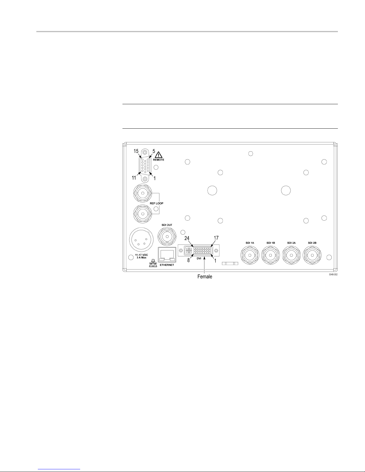
Figure 3: WFM5200 rear panel
WFM5200 Series System Integrator 5
Instrument connectors
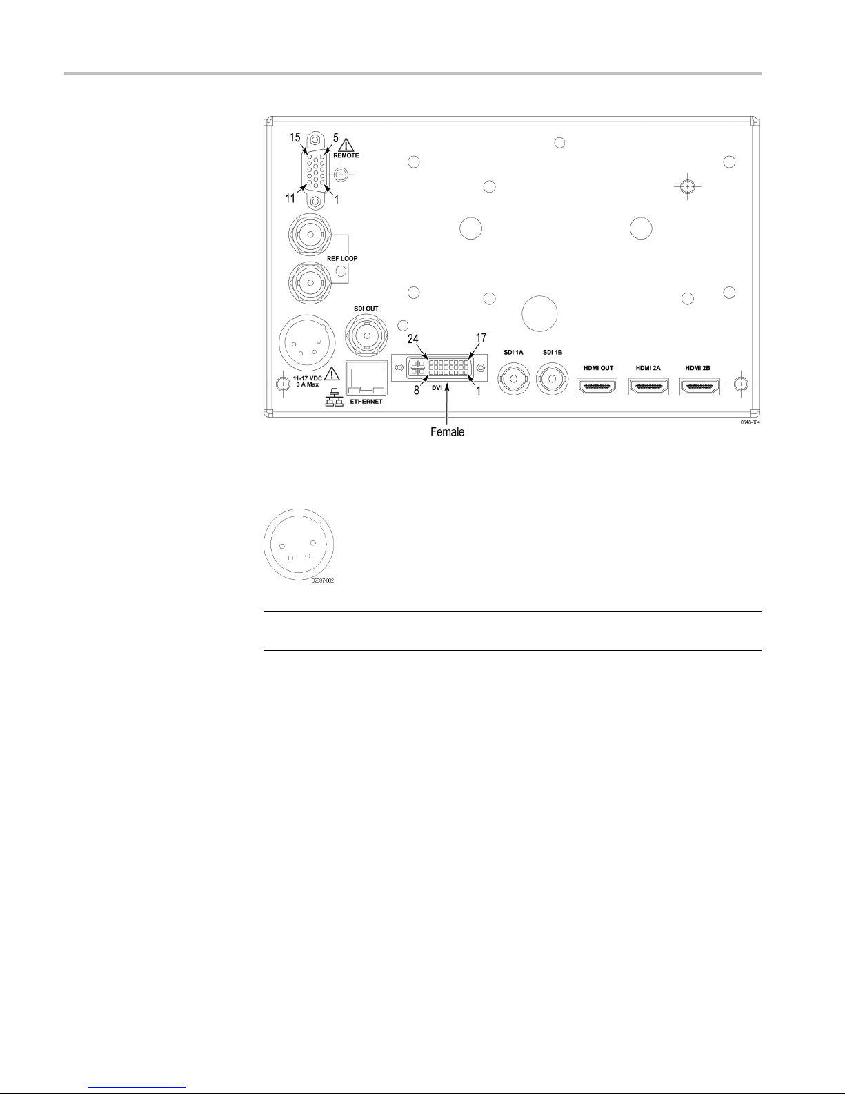
Figure 4: WFM5250 rear panel
Power connector
NOTE. If you ordered a power cord, it will come with a ferrite core. Install the
ferrite core as shown in the instructions with which it was shipped.
6 WFM5200 Series System Integrator
Instrument connectors
The instrument
operates from an external AC adapter and has the following power
requirements:
A single-phas
e power source with one current-carrying conductor at or near
earth-ground (the neutral conductor).
The power so
urce frequency must be 50 or 60 Hz, and a operating voltage
range must be from 100 to 240 VAC, continuous.
WAR N ING. To re d uc e r is k of fire and shock, make sure the mains supply voltage
fluctuations do not exceed 10% of the operating voltage range.
Systems with both current-carrying conductors live with respect to ground
(such as phase-to-phase in multiphase systems) are not recommended as
power sources.
NOTE. Only the line conductor is fused for over-current protection. The fuse is
al and not user replaceable. Do not attempt to replace the fuse. If you
intern
suspect the fuse has blown, return the unit to an authorized service center for
repair.
WFM5200 Series System Integrator 7

Instrument connectors
SDI video connectors
SDI inputs are s
elf-terminating inputs. Use the SDI 1A, 1B, 2A, and 2B inputs to
connect a serial digital video signal to the instrument.
NOTE. The SDI 2A and 2B connectors are only found on the WFM5200 model.
The SDI OUT can be selected to output either the looped-through input signal
or a test signal that contains configurable error brightups. This is done from the
Config > Outputs > SDI Output menu.
The following table lists the characteristics of the SDI video connectors.
Table 4: SDI video connector specifications
Connector Characteristic Description
NOTE. The SDI 2A and 2B
connectors are only found on
the WFM5200 model.
Input Type
Input Level
Cable Loss Accommodation: 270 Mb/s 0 to 30 dB attenuation at ½ of serial rate
Cable Loss Accommodation: 1.5 Gb/s,
3Gb/s
Output Type BNC, 75 Ω internally terminated
Output Level 800 mV ± 10% into 75 Ω load
BNC, 75 Ω internally terminated
WFM5250 only: 2 inputs, only one active at
a time except for Dual Link (2 inputs) or SIM
mode (Option SIM).
WFM5200 only: 4 inputs, only one active at
a time except in camera balance mode (2-4
inputs) or Dual Link (2 inputs).
800 mV ± 10%
Equivalent to approximately 300 m of
Belden 8281 at 270 Mb/s
0 to 20 dB attenuation at ½ of serial rate
Equivalent to approximately 80 m of
Belden 8281 at 1.485 Gb/s. Typical
performance to 110 m
MI video connectors
HD
(WFM5250 only)
HDMI inputs are self-terminating inputs. Use the HDMI 2A and 2B inputs to
route incoming HDMI signals into the rear-panel of the instrument. You cannot
monitor a 3D signal and an HDMI signal at the same time. You can only monitor
one at a time.
TheHDMIOUTcanbeusedtooutputanHDMIsignaltoanexternalHDMI
monitor. An HDCP compliant monitor is required in order to view an image for
HDCP compliant inputs, otherwise the screen may be blank. Also, the SDI output
will not be available when HDCP content is present on the HDMI input.
8 WFM5200 Series System Integrator

Instrument connectors
The following t
able lists the characteristics of the HDMI connectors.
NOTE. The HDMI 2A and 2B connectors are only found on the WFM5250 model.
Table 5: HDMI
Connector Characteristic Description
connector specifications
Input Type Type A conne
Format
Audio Uncompressed audio over HDMI is supported
HDCP HDCP version 1.4 is supported on both
Output T
Video
Audio
HDCP HDCP version 1.4 is supported on both
ype
2 inputs, only one active at a time
Supported formats include: 525i, 625i, 525p,
625p, 720p, 1080i, 1080p
(up to 8 channels)
inputs
BNC, 75 Ω
utput is always a loopout of the
Video o
currently selected HDMI input
Audio is passed from the HDMI input to the
output
s. If HDCP is present on the currently
input
selected input, it will be enabled on the
output.
ctor
internally terminated
Video external reference
connector
Use the REF LOOP connector to input a composite Black Burst signal or a
tri-level sync signal for use as a sync tim ing reference for the selected video
ut signal. The following table lists the signal characteristics of the external
inp
reference connectors.
Table 6: External reference connector specifications
Connector Characteristic Description
Input Type
Input Level -6 to +6 dB
Maximum Input Voltage Level
Maximum Absolute Input Voltage
BNC, passive loop-through, 75 Ω
ompensated
c
±5V,DC
±5V,DC
WFM5200 Series System Integrator 9

Instrument connectors
Remote connector
(WFM5200 only)
The REMOTE conn
contacts. It uses ground closures for remote control and sending indications to
ector is a 15-pin, female, D-type connector with socket
external equipment when alarms have occurred. The input of LTC is through the
REMOTE connector.
Use the Remote connector to input LTC time code signals, and to remotely select
one of the first four instrument presets in group “A” using ground closure. The
following table lists the signal characteristics of the Remote connector.
Table 7: WFM5200 remote connector pin assignments and preset functions
Characteristic Pin out Preset functions
Connector Pin Assignments
Characteristic
LTC Input Connector 15-pin DSUB, balanced, unterminated
LTC Input Signal Longitudinal Time Code per IEC Publication 461
LTC Signal Amplitude Range 0.2 V
Ground Closure Input Signal
Ground Closure Output Signal One open collector output
1GND(In)
2 Reserved (I/O)
3 Reserved (I/O)
4 Reserved (In)
5 Reserved (In)
6GND(In)
7 Time Code Positive (LTC In)
8 Time Code Negative (LTC In)
9 Ground Closure (Alarm Out)
10 Preset 1 (In)
11 Preset 2 (In)
12 Preset 3 (In)
13 Preset 4 (In)
14 Preset 5 (In)
15 Preset 6 (In)
Description
to 5.0 V
p-p
TTL thresholds, 5 V max input, -0.5 min input; pull low to assert
balanced differential or single-ended
p-p
Hex Binary
Pins 15,
14, 13,
12, 11,
10
F 111111
E XX1110 Preset 1 No action
D XX1101 Preset 2 No action
C
B XX1011 Preset 3
A XX1010 No action
9 XX1001 No action
8 XX1000 Preset 8
7
6 XX0110 Preset 6
5
4 XX0100 Preset 4
3 XX0011 Preset 3
2 XX0010 Preset 2
1 XX0001 Preset 1
0 XX0000 Unused
N/A
N/A
XX1100
XX0111 Preset 4 Preset 7
XX0101 Preset 5
10 1111 Preset 5
011111 P reset 6
Direct
mode
selection
none
Encoded
mode
selection
No action
SDI 1B/2B
SDI 1A/2A
N/A
N/A
10 WFM5200 Series System Integrator

Instrument connectors
Remote connector
(WFM5250 only)
The REMOTE conn
contacts. It uses ground closures for remote control and sending indications to
ector is a 15-pin, female, D-type connector with socket
external equipment when alarms have occurred. The input of LTC is through the
REMOTE connector.
Use the Remote connector to input LTC time code signals, and to remotely select
one of the first four instrument presets in group “A” using ground closure. The
following table lists the signal characteristics of the Remote connector.
Table 8: WFM5250 remote connector pin assignments and preset functions
Characteristic Pin out Preset functions
Connector Pin Assignments
Characteristic
LTC Input Connector 15-pin DSUB, balanced, unterminated
LTC Input Signal Longitudinal Time Code per IEC Publication 461
LTC Signal Amplitude Range 0.2 V
Ground Closure Input Signal
Ground Closure Output Signal One open collector output
1GND(In)
2 Reserved (I/O)
3 Reserved (I/O)
4 Reserved (In)
5 Reserved (In)
6GND(In)
7 Time Code Positive (LTC In)
8 Time Code Negative (LTC In)
9 Ground Closure (A larm Out)
10 Preset 1 (In)
11 Preset 2 (In)
12 Preset 3 (In)
13 Preset 4 (In)
14 Preset 5 (In)
15 Preset 6 (In)
Description
to 5.0 V
p-p
TTL thresholds, 5 V max input, -0.5 min input; pull low to assert
balanced differential or single-ended
p-p
Hex Binary
Pins 15,
14, 13,
12, 11,
10
F 111111
E XX1110 Preset 1 HDMI B
D XX1101 Preset 2 HDMI A
C
B XX1011 Preset 3
A XX1010
9 XX1001
8 XX1000 Preset 8
7
6 XX0110 Preset 6
5
4 XX0100 Preset 4
3 XX0011 Preset 3
2 XX0010 Preset 2
1 XX0001 Preset 1
0 XX0000 Unused
XX1100
XX0111 Preset 4 Preset 7
XX0101 Preset 5
Direct
mode
selection
none
Encoded
mode
selection
No action
SDI B
SDI A
Channel B
Channel A
WFM5200 Series System Integrator 11

Instrument connectors
EXT DISPLAY connector
The EXT DISPLAY
connector is a female DVI-I connector with socket contacts.
This is the external display monitor output. The display resolution is 1024 x
768. The output supports DVI monitors directly and analog PC (RGB) monitors
with the use of a DVI-I to VGA adapter.
12 WFM5200 Series System Integrator

Instrument connectors
Table 9: EXT DIS
Connector Pin Description Pin Description
Characteristic
Output Connector DVI-I (integrated, digital and analog)
PLAY connector specifications
1
2
3
4
5
6
7
8 Analog vertical sync 20
9
10
11
12
C1
C2
C3
Description
TMDS Data 2–
Red – (Link 1)
TMDS Data 2+
Red + (Link 1)
TMDS Data 2/4 shield
TMDS Data 4–
Green – (Link 2)
TMDS Data 4+
Green + (Link 2)
DDC clock
DDC data
TMDS Data 1–
Green – (Link 1)
TMDS Data 1+
Green + (Link 1)
TMDS Data 1/3 shield
TMDS Data 3–
Blue – (Link 2)
Analog red
Analog green
Analog blue
13
14
15 + 5 V
16 Hot plug detect
17
18
19
21
22
23
24
C4
C5
TMDS Data 3+
Blue + (Link 2)
Ground
Power for monitor when in standby
TMDS Data 0–
Blue – (Link 1) and digital sync
TMDS Data 0+
Blue + (Link 1) and digital sync
TMDS data 0 /5 shield
TMDS Data 5–
Red – (Link 2)
TMDS Data 5+
Red + (Link 2)
TDMS clock shield
TDMS clock +
Digital clock + (Links 1 and 2)
TDMS clock –
Digital clock – (Links 1 and 2)
Analog horizontal sync
Analog ground
Return for R, G, B signals
WFM5200 Series System Integrator 13

Instrument connectors
Ethernet connector
Use the Etherne
t connector to connect the waveform monitor to your local
network. A network connection is required for remote control, software upgrades,
and enabling some instrument options.
The Ethernet connector includes built-in green and yellow LEDs to indicate signal
status as indicated below:
Lit green LED indicates connection is active
Lit yellow L
ED indicates a 100 MB transmission rate
Unlit yellow LED indicates a 10 MB transmission rate
The following table lists the signal characteristics of the Ethernet connector.
Table 10: Ethernet connector pin assignments
Connector Pin/LED Name Description
1 TX_D1+ Transceive Data+
2 TX_D1- Transceive Data-
3 RX_D2+ Receive Data+
4 Not used
Characteristic
Ethernet connector
5
6 RX_D2- Receive Data-
7
8 Not used
Description
RJ-45 LAN supporting 10/100/1000 B aseT; supports manual and DHCP address modes
Not used
Not used
14 WFM5200 Series System Integrator

Instrument connectors
Headphone jack
Use the headpho
ne jack, located on the front panel, to listen to the audio associated
with the selected video input signal. The following table describes the signal
characteristics of the headphone jack.
Table 11: Headphone jack specifications
Connector Characteristic Description
Output Type Standard 1/4-inch stereo phone jack,
capable of driving a 6.25 dBu sine wave into
32 Ω or 16 Ω
USB Connec
tor
Use the USB connector, located on the front panel, to save and restore instrument
presets and captured data using a USB memory drive. The following table
describes the signal characteristics of the USB connector.
Table 12
Connector Characteristic Description
: USB connector specifications
Type Host
Speed Compli
es with USB 1.1 and 2.0 Full Speed
Specification (12 Mb/s)
WFM5200 Series System Integrator 15

Video system installation
Video system installation
The instrument can operate almost anywhere in the distribution system.
NOTE. See the Specifications and Performance Verification manual on the
Product Doc
umentation CD for maximum-allowed cable lengths.
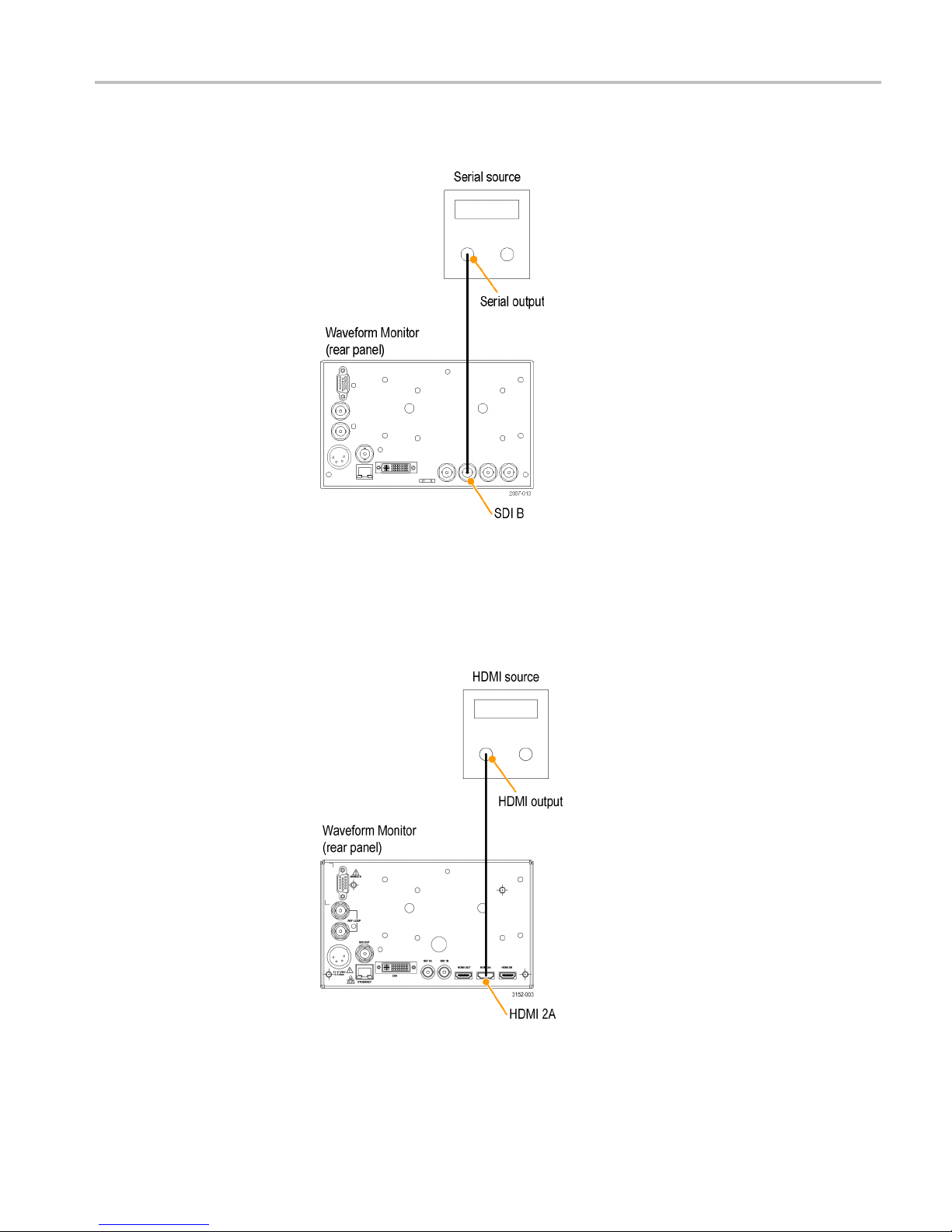
Install to monitor the
video bit st
ream of a serial
receiver
Route one or more incoming serial signals into the SDI inputs on the rear-panel
of the inst
Figure 5: Connecting SD, HD, or 3 Gb/s SDI signals to a WFM5200
rument.
NOTE. See the Specifications and Performance Verification manual on the
Product Documentation CD for maximum-allowed cable lengths.
16 WFM5200 Series System Integrator
Video system installation
Install to monitor the
embedded audio signal
in a serial digital video
stream
Route the incom
Figure 6: Connecting an SD, HD, or 3 Gb/s SDI signal with embedded audio
ing serial signal into one of the instrument SDI inputs.
Install to monitor the HDMI
content of a signal
You can route one incoming HDMI signal into one of the HDMI inputs on the
rear-panel of the instrument. You cannot monitor a 3D signal and an HDMI
signal. You can only monitor one at a time .
WFM5200 Series System Integrator 17

Video system installation
Install to output an HDMI
signal to an external
monitor
You c an output a
OUT connector.
NOTE. An HDCP compliant monitor is required in order to view an image for
HDCP compliant inputs, otherwise the screen may be blank. Also, the SDI output
will not be available when HDCP content is present on the HDMI input.
n HDMI signal to an external HDMI monitor using the HDMI
Install to monitor the
external referenc e signal
Route the incoming reference signal into one of the instrument REF inputs and
terminate the other connector with a 75 Ω terminator to ensure a closed loop.
Figure 7: Connecting an external reference signal
18 WFM5200 Series System Integrator

Video system installation
Line termination
Compatibility of BNC
center pins
You r ins tr um e n
t uses a passive loop-through reference input. Accordingly, the
loop-through input must be terminated externally. It is important that this external
termination meets accuracy and return loss requirements.
If the instrument is installed to monitor an operating link, the destination receiver
and the connecting cable serve as the termination. This monitoring connection
checks the performance of the entire path. The return loss of the instrument is
sufficiently high that, in most cases, the destina tion receiver sets the system return
loss.
In cases where the instrument is placed at the end of a link, a BNC termination
must be installed on one side of the loop-through reference connector. The
terminat
ion m ust be 75 Ω and DC coupled (good return loss extends to DC). An
appropriate termination for the EXT REF connector is Tektronix part number
011-0163-00, which is a 75 Ω, End-of-Line termination.
Most BNC
connectors for video equipment, whether 50 Ω or 75 Ω,usea50Ω
standard center pin. Some laboratory 75 Ω BNCconnectorsuseasmaller
diameter center pin. The BNC connectors on the instrument are designed to work
with the 50 Ω standard (large diameter) center pins.
Do not use connectors or terminators with the smaller center pins. They could
cause intermittent connections.
WFM5200 Series System Integrator 19

Power-on and power-off procedure
Power-on and p
AC power requirements
Power-
on
ower-off procedure
This instrum
conductor at or near earth ground. The line conductor is fused for over-current
protection. A protective ground connection through the grounding conductor in
the power cord is essential for safe operation.
The instrument operates from an external AC adapter with a line frequency of 50 or
60 Hz, over the range of 100-240 Volts, without the need for configuration, except
the power cord. The typical power draw is 27 Watts. Refer to the Specifications
and Performance Verification Technical Reference on the Product Documentation
CD for additional information on power and environmental requirements.
If you are using a battery as a power source, read the battery information provided
in Installation and Safety Instructions.
1. Connect the supplied power cord to the rear-panel power connector. If you are
using a battery, connect the battery as explained in the installation instructions
that come with the battery.
2. Press the power button on the instrument front-panel and the instrument will
turn on.
ent operates from a single-phase power sourc e with the neutral
Figure 8: WFM5200 front-panel
20 WFM5200 Series System Integrator

Power-on and power-off procedure
Power-off
Figure 9:
WFM5250 front-panel
NOTE. The power button on the front-panel does not disconnect mains power.
Only the power cord at the rear of the product can disconnect mains power.
Make sure that the power cord is accessible when the product is operating.
1. Press
the power button on the instrument front-panel to turn the instrument off.
2. To remove power completely, disconnect the power cord from the rear-panel
e instrument.
of th
WFM5200 Series System Integrator 21

Network operation
Network operation
This section provides the following information for operating the instrument on
alocalLANnetwork:
How to configure the instrument for operation on an IP network
How to configure the instrument to send and/or receive SNMP remote
commands
How to use a Web browser to start a remote application to enable control
of the instrument, or to download the Event and Diagnostic log files, or to
capture images of the instrument display
Ethernet
connection
Connect the instrument to your network using an Ethernet cable. You can connect
it directly to the instrument or through a HUB, as shown below.
Figure 10: Connecting to ethernet
22 WFM5200 Series System Integrator

Network operation
IP settings con figuration
To allow networ
k access to the instrument, you need to set the IP address.
Network addresses can b e assigned either automatically (DHCP) or manually. If
your network does not use DHCP, you will have to manually enter the address for
the instrument. To obtain a valid IP address, contact your LAN administrator.
Perform the following steps to configure the IP settings on the instrument:
1. Press the CONFIG button to display the Configuration menu.
2. Use the Gene
ral knob to navigate to Network Settings.
3. Press the right arrow key to select IP ConfigMode.
4. Press the SEL button to select between DHCP and Manual.
5. If you selected DHCP, you are finished.
6. If you selected Manual mode, you need to set the Subnet Mask and Gateway
Address parameters. Contact your LAN administrator for these values. (Be
sure to use compatible addresses between the PC and the instrument.)
7. Press the down arrow key to select IP Address.
8. Press the right arrow key. A dialog box will appear that allows you to enter
the IP address.
9. Repeat steps 7 and 8 for the Subnet Mask and the Gateway Address.
10. If desired, select Instrument Name and then press the right arrow button to
assign the instrument a network name.
11. Press the CONFIG button to close the configuration menu.
WFM5200 Series System Integrator 23

Network operation
SNMP remote control
configuration
SNMP remote con
trol is primarily intended for instrument access using automated
systems. If you intend to use SNMP commands to control the instrument, you
must first configure the SNMP settings on the waveform monitor.
NOTE. The SNMP commands are contained in a MIB (Management Information
Base). Refer to the WFM Series Waveform Monitors and WVR Series Waveform
Rasterizers Management Information Base Technical Reference (Tektronix
part number
077-0261-XX) for information about using the MIB to control the
waveform monitor.
The proce
dure to configure SNMP settings is similar to that previously described
for configuring the IP settings. Touch SNMP Setup in the Communication
submenu of the Main menu to configure the following SNMP parameters:
Remote SNMP Enable. Use this setting to configure the remote access to the
instrument via SNMP. You can select Off or On.
SNMP Traps. Use this setting to enable or disable the SNMP traps that are
sent from the instrument when error conditions are detected.
Trap Destination Address. Use these settings to enter up to four different
IP addresses to which SNMP traps will be sent when error conditions are
detected.
NOTE. A value of all zeroes for the IP address will disable that trap output.
Private Community String. Use this menu setting to enter the Private
Community string, which effectively is a password. Without this string,
SNMP commands cannot change values in the waveform monitor.
TE. Use the Private Community String to control the ability of SNMP
NO
commands to make changes to the waveform monitor. Use the Public Community
String to control the ability of SNMP commands to read information from the
waveform monitor.
Public Community String. This menu entry allows you to set the Public
Community string. This string is effectively a password. Without this s tring,
SNMP commands cannot read information from the instrument.
24 WFM5200 Series System Integrator

Network operation
Web browser operation
You can connect
to an instrument installed on an Ethernet IP network without
installing any software and using only a Web browser. Using the Web browser,
you can perform the following functions:
Start a remote application to enable control of the instrument
Download th
e Event and Diagnostic log files
Capture images of the instrument display
Perform the following steps to connect to the instrument using a Web browser:
1. Verify that the instrument has been configured for IP network operation and
note the IP address. (See page 23, IP settings configuration.)
2. Press the CONFIG button.
3. Use the General knob to navigate to Network Settings.
4. Press the right arrow key and then use the General knob to navigate to Web
Enable.
5. Press the SEL buttontoselectOn.
6. On you
r PC, start your Web browser and enter the network address of the
instrument into the URL entry box like this:
//123.123.123.123/
http:
NOTE. Many Web browsers do not correctly interpret IP addresses with leading
zeros. If the IP address shown in the Configuration menu contains leading zeros,
remove any leading zeros when you enter the address in the browser.
For example, the IP address 124.161.038.092 should be entered as follows:
124.161.38.92
7. The Web browser will display the remote interface for the instrument. To
make a selection, click the desired link.
WFM5200 Series System Integrator 25
 Loading...