

Page 1

WFM2200
xx
ZZZ
SD/HD/3G SDI Waveform Monitor & Generator
User Manual
*P077066100*
077-0661-00
Page 2

Page 3

xx
WFM2200
ZZZ
SD/HD/3G SDI Waveform Monitor & Generator
User Manual
This document supports software version 1.0 and above.
www.tektronix.com
077-0661-00
Page 4

Copyright © Tektronix. All rights reserved. Licensed software products are owned by Tektronix or its subsidiaries
or suppliers, and are protected by national copyright laws and international treaty provisions.
Tektronix products are covered by U.S. and foreign patents, issued and pending. Information in this publication
supersedes that in all previously published material. Specifications and price change privileges reserved.
TEKTRONIX and TEK are registered trademarks of Tektronix, Inc.
Contacting Tektronix
Tektronix, Inc.
14150 SW Karl Braun Drive
P.O. B o x 5 0 0
Beaverto
USA
For product information, sales, service, and technical support:
n, OR 97077
In North America, call 1-800-833-9200.
Worl dwid e, vi sit www.tektronix.com to find contacts in your area.
Page 5

Warranty
Tektronix warrants that this product will be free from defects in materials and workmanship for a period of o ne (1)
year from the date of shipment. If any such product proves defective during this warranty period, Tektronix, at its
option, either will repair the defective product w ithout charge for parts and labor, or will provide a replacement
in exchange for the defective product. Parts, modules and replacement products used by Tektronix for warranty
work may be n
the property of Tektronix.
ew or reconditioned to like new performance. All replaced parts, modules and products become
In order to o
the warranty period and make suitable arrangements for the performance of service. Customer shall be responsible
for packaging and shipping the defective product to the service center designated by Tektronix, with shipping
charges prepaid. Tektronix shall pay for the return of the product to Customer if the shipment is to a location within
the country in which the Tektronix service center is located. Customer shall be responsible for paying all shipping
charges, duties, taxes, and any other charges for products returned to any other locations.
This warranty shall not apply to any defect, failure or damage caused by improper use or improper or inadequate
maintenance and care. Tektronix shall not be obligated to furnish service under this warranty a) to repair damage
result
b) to repair damage resulting from improper use or connection to incompatible equipment; c) to repair any damage
or malfunction caused by the use of non-Tektronix supplies; or d) to service a product that has been modified or
integrated with other products when the effect of such modification or integration increases the time or difficulty
of servicing the product.
THIS WARRANTY IS GIVEN BY TEKTRONIX WITH RESPECT TO THE PRODUCT IN LIEU OF ANY
OTHER WARRANTIES, EXPRESS OR IMPLIED. TEKTRONIX AND ITS VENDORS DISCLAIM ANY
IMPLIED WARRANTIES OF MERCHANTABILITY OR FITNESS FOR A PARTICULAR PURPOSE.
TRONIX' RESPONSIBILITY TO REPAIR OR REPLACE DEFECTIVE PRODUCTS IS THE SOLE
TEK
AND EXCLUSIVE REMEDY PROVIDED TO THE CUSTOMER FOR BREACH OF THIS WARRANTY.
TEKTRONIX AND ITS VENDORS WILL NOT BE LIABLE FOR ANY INDIRECT, SPECIAL, INCIDENTAL,
OR CONSEQUENTIAL DAMAGES IRRESPECTIVE OF WHETHER TEKTRONIX OR THE VENDOR HAS
ADVANCE NOTICE OF THE POSSIBILITY OF SUCH DAMAGES.
[W2 – 15AUG04]
btain service under this warranty, Customer must notify Tektronix of the defect before the expiration of
ing from attempts by personnel other than Tektronix representatives to install, repair or service the product;
Page 6

Page 7

Table of Contents
General Safety Summary ........................................................................................ vii
Preface .............................................................................................................. ix
Where to find more information............................... ................................ .............. ix
Conventions used in this manual.... .................................. ................................ ....... x
Getting started. . ..... . ..... . ..... . ..... . ... . . . .... . . .... . ..... . ..... . ..... . ..... . ..... . ..... . ..... . ..... . ... . . ..... . . 1
Product description ................... ................................ ................................ ......... 1
Options and optional accessories............................................................................. 4
Installation..................... ................................ .................................. ............... 6
Configure the network interface............................................................................. 16
Incoming inspection .......................................................................................... 21
Storing or shipping the instrument................ ................................ .......................... 23
Getting acquainted with your instrument ... . ..... . ..... . ..... ..... . ..... . ..... . ..... . ... . . . .... . ..... . ..... . ... 25
Front-panel controls ............................ .................................. ............................ 25
Online help .................................................................................................... 29
Instrument display ............................................................................................ 30
Signal inputs and outputs ............................... ................................ .......................... 37
Connectors..................................................................................................... 37
Signal inputs................................................................................................... 37
Connector configuration ........................... ................................ .......................... 39
Signal outputs ............................. ................................ ................................ .... 40
Display modes ... ................................ .................................. ................................ 42
ANC Data display (Option DATA only) ................................................................... 43
Arrowhead display.................. ................................ ................................ .......... 47
Audio display.................... .................................. ................................ ............ 49
Bowtie display ................................................................................................ 55
Datalist display (Option DATA only)....................................................................... 57
Diagnostics Monitor display................................................................................. 60
Diamond display ................ .................................. ................................ ............ 64
External Reference Waveform display ..................................................................... 66
Generator Status display ..................................................................................... 68
Lightning display ............................................................................................. 71
LTC Waveform display....................................................................................... 74
Picture display................................................................................................. 76
Split Diamond display........................................................................................ 79
Status displays................................................................................................. 81
AES Channel Status display ...... .................................. ................................ .... 82
Alarm Status display..................................................................................... 84
ARIB status displays .......................... .................................. ........................ 85
Audio Control Packet status display ................................................................... 86
WFM2200 Waveform Monitor & Generator User Manual i
Page 8

Table of Contents
Audio Session s
Auxiliary Data Status display... . ..... . ..... . ..... . ..... . ..... . ..... . ..... . . .... . . .... . . .... . . .... . . .... 92
Dolby Status display..................................................................................... 94
Error Log status display ............................. ................................ .................... 96
Video Session status display ............................................................................ 99
Timing Measure display ....... .................................. ................................ .......... 103
Vector display ............... ................................ .................................. .............. 107
Waveform display................. .................................. ................................ ........ 111
Functions ......................................................................................................... 115
Gain, sweep, and magnification ............................. ................................ .............. 115
Measurement cursors (Waveform display only)......................... ................................ 119
Display capture (freeze)............................ .................................. ...................... 121
Line select ......... ................................ ................................ .......................... 122
Audio volume and source adjustment .... ................................ ................................ 124
Presets........................................................................................................ 125
Software upgrades ............................. ................................ ................................ .. 131
Before you begin............................................ .................................. .............. 131
Software upgrade overview.... .................................. ................................ .......... 132
USB software installation.................................................................................. 133
Network software installation ....... ................................ ................................ ...... 135
Verify the software and installed options................................................................. 136
Software installation troubleshooting............. ................................ ........................ 137
Checking chroma/luma delay .................................................................................. 139
Checking gamut.................... .................................. ................................ ............ 141
To set up gamut checks..................... ................................ ................................ 141
Checking RGB gamut .............................. .................................. ...................... 142
Checking composite gamut ................................................................................ 145
Checking luma gamut ...................................................................................... 146
Automating gamut checks . ................................ .................................. .............. 146
ARIB content displays .......................................................................................... 147
To enable the ARIB content displays..................................................................... 147
ARIB Status display........................................................................................ 148
ARIB STD-B.39 display ................................................................................... 149
ARIB STD-B.37 display and status screens ......................... ................................ .... 152
ARIB STD-B.35 display and status screens ......................... ................................ .... 155
ARIB TR-B.23 (1) display and status screens ......................... .................................. 157
ARIB TR-B.23 (2) display and status screens ......................... .................................. 159
ARIB TR-B.22 display and status screens ....... ................................ ........................ 161
Audio monitoring.................................... ................................ ............................ 163
To configure embedded audio inputs and alarms........................................................ 163
To display an audio input .................................................................................. 164
tatus display...................................... .................................. .... 89
ii WFM2200 Waveform Monitor&GeneratorUserManual
Page 9

Table of Contents
To check audio l
To monitor embedded 16-channel audio ................................................................. 167
To check surround sound. . ..... . ... . . ..... . ..... . ..... . .... . . .... . ..... . ..... . ..... . .... . ..... . ..... . ..... . 168
Closed captioning (CC), teletext, AFD, and safe area compliance..................... .................... 172
Monitoring CC and teletext................................................................................ 172
Monitoring for safe area compliance ........... .................................. ........................ 176
Monitoring
Application examples ....................... ................................ .................................. .. 178
Timing a studio.............................................................................................. 178
Troubleshooting cable problems ................ .................................. ........................ 183
Index
evel and phase ........................................................................... 164
for AFD compliance.......................................................................... 177
WFM2200 Waveform Monitor & Generator User Manual iii
Page 10

Table of Contents
List of Figure
Figure 1: Instrument online help....................... ................................ .......................... 29
Figure 2: Navigate menus using the arrow keys and select button..................... ...................... 31
Figure 3: Display quadrants and related tile numbers ... . ..... . ..... . . ...... . . ..... . . ..... . . ..... . . ..... . . .... 32
Figure 4: Changing from 4-tile to full-screen view .... . . .... . ..... . ..... . ..... . ..... . ..... . ..... . ..... . ..... . . 33
Figure 5: Thumbnail view in Waveform display............................................................... 34
Figure 6: Elements of the Status bar .......................... .................................. ................ 35
Figure 7: Placement of dual link information in the Waveform display............................. ........ 38
Figure 8: Video signal generation con
Figure 9: AES audio signal generation connection ............................................................ 41
Figure 10: ANC Data display (full screen mode).............................................................. 43
Figure 11: Arrowhead display ................................................................................... 47
Figure 12: Audio display (Surround mode) .. ................................ .................................. 49
Figure 13: Bowtie display ........................................................................................ 55
Figure 14: Datalist display ....................................................................................... 57
Figure 15: Diagnostics Monitor display (page 1).............................................................. 61
Figure 16: Diagnostics Monitor display (page 2).............................................................. 61
Figure 17: Diagnostics Monitor display (page 3).............................................................. 62
Figure 18: Diagnostics Monitor display (page 4).............................................................. 62
Figure 19: Diamond display.................................. ................................ .................... 64
Figure 20: External Reference Waveform display (tri-level sync signal) ....... ............................ 66
Figure 21: Generator Status display ............................................................................. 68
Figure 22: Construction of the Lightning display............................ ................................ .. 71
Figure 23: Lightning display ..................................................................................... 72
Figure 24: LTC Waveform display .............. ................................ ................................ 74
Figure 25: Picture display of color bars signal with Safe Area and Picture Center graticules enabled .. 76
Figure 26: Split Diamond display ................... ................................ ............................ 79
Figure 27: AES Chan
Figure 28: Alarm Status display ................................................................................. 84
Figure 29: Format of the Audio Control Packet ............................................................... 86
Figure 30: Structure of the Audio Control Packet ........................... .................................. 86
Figure 31: Audio Control Packet status display................................................................ 87
Figure 32: Audio Session status display .. ................................ .................................. .... 89
Figure 33: Auxiliary Data Status display . ..... . ..... . ..... . .... . . .... . ..... . ..... . ..... . ..... . ..... . .... . ..... . 92
Figure 34: Dolby Status display ................................................................................. 94
Figure 35: Error Log status display ......................... ................................ .................... 96
Figure 36: Video Session status display of an HD signal ..................................................... 99
Figure 37: Timing Measure display ........................................................................... 103
Figure 38: Timing display of non-integer multiples of reference rates .... . . .... . ..... . ..... . ..... . ..... . . 106
s
nection.................................................................. 40
nel Status display......................................................................... 82
iv WFM2200 Waveform Monitor&GeneratorUserManual
Page 11

Table of Contents
Figure 39: Vect
Figure 40: Vector display in Composite mode ............................................................... 108
Figure 41: Using measurement cursors in the Waveform display.......................................... 120
Figure 42: Navigating line selection .......................................................................... 123
Figure 43: Sample of transfer.exe window after the upgrade is complete ...... .......................... 136
Figure 44: Determining transition intersections in the Lightning display. . . .... . ..... . ..... . ..... . ... . . .. 140
Figure 45: D
Figure 46: Out-of-gamut examples............................ ................................ ................ 143
Figure 47: Arrorwhead gamut display plots.................................................................. 145
Figure 48: ARIB Status display, showing no ARIB data present .......................... ................ 148
Figure 49: ARIB STD-B.39 display (with the associated ARIB Status display) ......................... 149
Figure 50: ARIB STD-B.37 display (with the associated ARIB Status display) ......................... 152
Figure 5
Figure 52: ARIB TR-B.23 (1) display (with the associated ARIB Status display) ...................... 157
Figure 53: ARIB TR-B.23 (2) display (with the associated ARIB Status display) ...................... 159
Figure 54: ARIB TR-B.22 display (with the associated ARIB Status display)........................... 161
Figure 55: Audio levels............... ................................ ................................ .......... 165
Figure 56: Checking for phase correlation ................. ................................ .................. 166
Figu
Figure 58: Surround sound indicators. ................................ ................................ ........ 169
Figure 59: Auxiliary Data Status display . . .... . ..... . ..... . ..... . ..... . ... . . . .... . ..... . ..... . ..... . ..... . ... 174
Figure 60: Closed caption display area ....................................................................... 175
Figure 61: Safe Action and Safe Title areas . . ..... . .... . . .... . ..... . ..... . ..... . ... . . ..... . ..... . ... . . . .... . . 177
1: ARIB STD-B.35 display (with the associated ARIB Status display)......................... 155
re 57: 16-Channel audio bars display .................................................................... 168
or display in Normal mode with the compass rose and I/Q axis graticules enabled ... 107
iamond display plot .............................................................................. 142
WFM2200 Waveform Monitor & Generator User Manual v
Page 12

Table of Contents
List of Tables
Table i: Product documentation.................................................................................. ix
Table 1: Key
Table 2: Instrument options .......... ................................ .................................. ........... 4
Table 3: Optional accessories ..................................................................................... 4
Table 4: Power cord options........ ................................ .................................. ............. 5
Table 5: Service options ........................ ................................ ................................ ... 5
Table 6: Battery charge-level meter icons .......... ................................ ............................ 13
features .............................................................................................. 2
vi WFM2200 Waveform Monitor & Generator User Manual
Page 13

General Safety Summary
General Safet
To Avoid Fi
re or Personal
Injury
ySummary
Review the fo
this product or any products connected to it.
To avoid pot
Only qualified personnel should perform service procedures.
Use proper
certified for the country of use.
Observe a
and markings on the product. Consult the product manual for further ratings
information before making connections to the product.
Do not apply a potential to any terminal, including the common terminal, that
exceeds the maximum rating of that terminal.
Power disconnect. The power cord disconnects the product from the power source.
Do not block the power cord; it must remain acce ssible to the user at all times.
Do not operate without covers. Do not operate this product w ith covers or panels
removed.
llowing safety precautions to avoid injury and prevent damage to
ential hazards, use this product only as specified.
power cord. Use only the power cord specified for this product and
ll terminal ratings. To avoid fire or shock hazard, observe all ratings
Do not operate with suspected failures. If you suspect that there is damage to this
product, have it inspected by qualified service personnel.
Avoid exposed circuitry. Do not touch exposed connections and components when
power is present.
Replace batteries properly. Replace batteries only with the specified type and
rating.
Recharge batteries properly. Recharge batteries for the recommended charge cycle
only.
Use proper AC adapter. Use only the AC adapter specified for this product.
o not operate in wet/damp conditions.
D
Do not operate in an explosive atmosphere.
Keep product surfaces clean and dry.
Provide proper ventilation. Refer to the manual's installation instructions for details
on installing the product so it has proper ventilation.
WFM2200 Waveform Monitor & Generator User Manual vii
Page 14

General Safety Summary
TermsinThisManual
Symbols and Terms on the
Product
These terms may
WARNING. Warning statements identify conditions or practices that could result
in injury or loss of life.
CAUTION. Caution statements identify conditions or practices that could result in
damage to this product or other property.
These terms may appear on the product:
DANGER in
the marking.
WARNING
read the marking.
CAUTIO
The following symbol(s) may appear on the product:
appear in this manual:
dicates an injury hazard immediately accessible as you read
indicates an injury hazard not immediately accessible as you
N indicates a hazard to property including the product.
viii WFM2200 Waveform Monitor&GeneratorUserManual
Page 15

Preface
This manual contains the following information to help you use the Tektronix
WFM2200 SD/HD/3G SDI Waveform Monitor & Generator:
How to set up various waveform displays for monitoring SD-SDI, HD-SDI,
and 3 Gb/s SDI video signals.
How to set up audio displays to monitor embedded AES/EBU audio signals.
How to set up parameters for monitoring auxiliary data, ancillary data, closed
captions, and timecode.
How to freeze video data.
How to s et up error logging and alarms.
How to operate the instrument remotely.
How to n a
vigate instrument menus.
How to operate the instrument front panel.
Where to find more information
This product is shipped with a Product Documentation CD that contains various
documents for all users and reference information for system integrators. The
user
following table shows you where you can find this and more information about
your product. You can always find the most updated documentation and software
for your product on the Tektronix Web site at www.tektronix.com/downloads.
Table i: Product documentation
To read about Tektronix part num ber Use these documents
Installation and safety
Instrument operation 077-0661-XX
Content-sensitive help topics
071-3018-XX
NA
Installation and Safety Instructions
ovides installation, safety, general specifications, and
Pr
compliance information.
This is a printed manual and is also available on the Web at
ww.tektronix.com/downloads.
w
ser Manual (this manual)
U
In-depth descriptions of instrument operation.
Available on the Web at www.tektronix.com/downloads.
Online Help
Detailed instrument operation and UI help is available in your
instrument by pressing the HELP button on the front panel of
the instrument.
WFM2200 Waveform Monitor & Generator User Manual ix
Page 16

Preface
Table i: Product documentation (cont.)
To read about Tektronix part number Use these documents
Specifications and procedures for
checking instrument performance
Information about declassifying the
instrument
Information about the WFM200BA
battery pack
Information about the WFM200BC
battery charger
077-0662-XX
077-0663-XX
075-1041-XX WFM200BA Rechargeable Battery Pack Instructions
075-1042-XX
Specifications and Performance Verification Technical
Reference
Physical, electrical, and environmental specifications; functional
checks and performance verification procedures.
Available on the Web at www.tektronix.com/downloads.
Declassification and Security Instructions
Detailed information about how to sanitize the instrument.
Available on the Web at www.tektronix.com/downloads.
Provides safety, operating, and recycling information for the
Lithium-Ion battery pac k.
This is a printed manual and is also available on the Web at
www.tektronix.com/downloads.
WFM200BC External Battery Charger Instructions
Provides safety and operating information for the optional,
external battery charger.
This is a printed manual and is also available on the Web at
www.tektronix.com/downloads.
Conventions used in this manual
The following icon is used throughout this manual:
Sequence step
or item
x WFM2200 Waveform Monitor & Generator User Manual
Page 17

Getting started
Your instrument was shipped with a printed Installation and Safety Instructions
manual which includes safety, compliance, and o perating requirements along with
power-on, in
online at www.tektronix.com/downloads. This User manual contains information
about operating the instrument.
This chapter will help you set up and begin to use the instrument. It is divided
into the following four sections:
Product description describes your instrument and provides a list of key
features.
Options and optional accessories lists the options and optional accessories
which are available for the instrument.
Network installation describes how to set up your instrument for use on an
Ethernet network.
Incoming inspection provides a procedure for verifying the basic operation
and functionality of your instrument.
stallation, and accessories information. That manual is also available
Product description
The WFM2200 SD/HD/3G SDI Waveform Monitor and Generator is a portable
baseband video monitor, offering uncompromised monitoring quality for field
applications with a large 6.5 inch high-brightness, low-power consumption LED
backlit display, and weighing in at less than 4.4 lbs (2 kg).
This instrument provides an array of basic monitoring tools for video (SD, HD,
Dual Link, and optional 3G) and audio (Embedded and AES) signals. You can
nfigure the instrument for a full screen or quad-tile display, which allows you to
co
see all of the necessary signal information at a glance. The ANC Data Inspector,
Data list, and closed caption decode features are invaluable for troubleshooting
problems within the ancillary data space.
You can use the Tektronix patented Timing display and the external reference
waveform display to assist in ensuring correct video timing and troubleshooting
timing problems. The instrument includes a color bar and pathological video
signal generator for troubleshooting signal paths and equipment.
A range of accessories can expand the versatility of the WFM2200 for field
operations such as production setup and troubleshooting. The instrument can
be powered by the supplied rechargeable/replaceable Li-Ion battery pack or the
supplied 100-240 V AC adapter, which provides 19 VDC to the instrument.
WFM2200 Waveform Monitor & Generator User Manual 1
Page 18

Getting started
Key features
The following k
ey features make this instrument an easy to use, flexible, and
effective tool.
Table 1: Key features
Item Description
Flexible til
Full and Quad Tile
Presets
Digital support
Fully digital
process
Video a
signal generation
Wavef
Vecto
Infinite Persistence All trace displays can also be set, tile by tile, to Infinite Persistence.
Gamut monitoring Arrowhead, Spearhead, Diamond, and Split Diamond displays offer
LTC waveform display Longitudinal Time Code (LTC) is monitored in a frame rate display
External Reference
Waveform display
edisplays:
ing
nd audio test
orm display
r display
Quad Tile (4-Tile): View four measurement displays at once, one
in each tile.
In Quad Tile
concurrent views of a monitored signal (with a maximum o f two
trace displays at once). The instrument also provides the flexibility
to configur
you to quickly check the integrity of a signal.
Full: View the active display full screen.
Customizable presets allow you to quickly save and recall
commonly
Support f
Fully Di
operation that surpasses traditional analog designs.
Multiengineers with a simple signal source for quick signal path
verification during system and/or equipment setup and
troubl
Tradi
paraded.
Vector display with Composite and Component Compass Rose
Graticules, and gain, sweep, and magnification controls. Traditional
and L
both luma and chroma amplitudes, and quantifies inter-channel
timing.
s mode traces waveforms over time on the same display,
Thi
providing a visual history of the trace.
user-selectable gamut thresholds so that you can set monitoring
mits appropriate to a specific operation. Ga mut monitoring is fully
li
integrated with the alarm logging and reporting capabilities.
to allow observation of amplitude and noise, and verify LTC is
ocked to the video.
l
The External Reference waveform display check the external
reference signal integrity, including its shape and amplitude. This
display is independent of the input video signal.
mode, the high-resolution LED display provides four
e each of the four display tiles independently, enabling
used configurations.
or digital applications.
gital Processing allows for accurate, repeatable, drift-free
rate color bar and pathological signal generation provides
eshooting.
tional waveform displays allow signals to be overlaid or
ightning Vector displays are available. The latter visualizes
2 WFM2200 Waveform Monitor & Generator User Manual
Page 19

Getting started
Table 1: Key features (cont.)
Item Description
Audio monitoring
Auxiliary data
monitoring
Timing display
Closed Captioning
support (Option DATA
only)
Picture area
Status screens Status screens provide content status at a glance.
Error tracking
Remote control
Data List display
Ancillary data
inspector
1
Audio Surround Sound Display licensed from Radio Technische Werksütten GmbH and Co. KG (RTW).
Surround Sound display of audio signals and phase relationships
of normal channel pairs.
16-channel embedded AES/EBU audio simultaneous monitoring
1
support with Multichannel Surround Sound
display, flexible
Lissajous display, and two channel AES/EBU BNC input monitoring.
The Lissajous display lets you monitor a user-specified pairing of
channel inputs.
Support and options for viewing and monitoring both levels of
normal channel pairs for embedded audio signals.
Support for audio control packet coding and many popular audio
scales, including BBC scales.
Support for monitoring auxiliary data including data conforming to
ARIB standards and CEA608, CEA708, AFD, and CGMS-A.
A Tektronix proprietary display that simplifies measuring the timing
difference between two signals. Using the Timing display enables
you to easily compare and correct the timing between two signals.
Support for simultaneous decode and display in multiple languages
of CC standards (CEA 608 (VBI), CEA 608 (ANC), CEA (608/708),
CEA 708, TeletextB (VBI), TeletextB OP47 S DP (ANC), and
TeletextB OP47 Multi (ANC)) with caption text and V-chip
information overlaid on the picture (monitor mode). There are also
settings for missing or incorrectly inserted closed captioning.
Support for standard and custom Safe Graticules for Picture
displays that look for incorrect placements of graphics, logos, Black
events, and Frozen events. Two Safe Area graticules and Safe
Title graticules are supported.
Configurable alarms and error logging.
Full remote control for complete installation flexibility.
Examines the contents of all digital formats, structures, and
transports and displays the data without any interpolation.
Allows you to monitor all ancillary data present in a signal.
WFM2200 Waveform Monitor & Generator User Manual 3
Page 20

Getting started
Options and op
Instrument o
tional accessories
Your instrument may have been ordered with one or more of the options listed in
this section.
ptions
The following options are available for the instrument:
Table 2: Instrument options
Option Description
3G Adds support for 3G-SDI (Level A and Level B) signal formats.
DATA Adds comp
Check the installed options.
When th
e instrument is powered on, you can check which options are installed on
your instrument by performing the following steps:
1. Press t
he CONFIG button on the front panel.
2. Use the General knob to navigate to Utilities.
rehensive data monitoring, which helps to quickly resolve
difficult content quality and reliability issues through closed captioning,
subtitles, AFD decode/display and full ANC data support.
Optional accessories
3. Press the right arrow button to navigate to the Utilities submenu and select
View Instrument Options. The menu box on the right side of the display
s the installed options.
show
You can purchase any of the following accessories for your instrument.
Table 3: Optional accessories
Accessory Description
WFM200BA Additional Li-Ion rechargeable battery pack. The instrument is shipped
with one WFM200BA rechargeable battery pack.
WFM200BC External battery charger for the WFM200BA rechargeable battery pack.
WFM200FSC Soft carrying case to protect the instrument with room for the instrument,
AC adapter, and battery pack(s).
4 WFM2200 Waveform Monitor & Generator User Manual
Page 21

Getting started
International power cord
options
The instrument
was shipped with an AC adapter and one of the following power
cord options. Power cords for use in North America are UL listed and CSA
certified. Cords for use in areas other than North America are approved by at least
one authority acceptable in the country to which the product is shipped.
Table 4: Power cord options
Option Descriptio
A0 North America power
A1 Universal EUR power
A2 United Kin
A3 Australia power
A5
A6 Japan power
A10
A11 India po
A12 Brazil power
1
A99
1
When ordering the A99 option, it is the responsibility of the end user to be sure that a certified power cord, for
ntry or region in which it is installed, is used with this instrument.
the cou
Switzerland power
China power
No power cord
n
gdom power
wer
Service options
You can add any or all of the following service options to any instrument. (See
Table 2 .)
e 5: Service options
Tabl
Option Description
C3 Adds 3 years of Calibration Service.
C5 Adds 5 years of Calibration Service.
D1
D3
5
D
3
R
R5
R3DW
R5DW
Adds a Calibration Data Report.
Adds 3 years of Calibration Data Report (when ordered with option C3).
Adds 5 years of Calibration Data Report (when ordered with option C5).
Adds 3 years of Repair Service (including the period under warranty).
This option is available only at the time that the product is purchased.
Adds 5 years of Repair Service (including the period under warranty).
This option is available only at the time that the product is purchased.
Adds 3 years of Repair Service (including the period under warranty).
This option is available only after the product is purchased.
Adds 5 years of Repair Service (including the period under warranty).
This option is available only after the product is purchased.
WFM2200 Waveform Monitor & Generator User Manual 5
Page 22

Getting started
Installation
Your handheld instrument is shipped in a fully enclosed metal chassis with a
protective rubber boot. A flange with a threaded hole is provided on the bottom
panel for use with a tripod mount.
If you need to install your instrument in a custom application, such as a console,
be sure to provide adequate airflow and make sure the intake air to the side vents
does not exceed 40 °C. Do not block or restrict the ventilating holes. See the
WFM2200 Sp
the complete operating specifications.
CAUTION. To prevent risk of fire, adequate airflow must be maintained. Failure
to provide adequate airflow to the instrument could cause the instrument to shut
down. Inadequate airflow includes placing the instrument in any small, enclosed
room that lacks a ventilation system, such as a closet. If the airflow is restricted or
blocked
the instrument could be permanently damaged.
ecifications and Performance Verification Technical Reference for
and the instrument does not shut down, the risk of fire is increased and
Power requirements
nstrument is designed to be powered by a 19 VDC input or by a Li-Ion
This i
rechargeable battery pack. However, the instrument will operate from any
regulated DC voltage between 11 V and 20 V. Input voltages below 18.5 V should
not be used while the battery pack is installed, as the battery pack will discharge
until it is below the input voltage level.
ower. When the instrument operates from an external AC adapter, the
AC p
following power requirements apply:
WARNING. Fire can cause personal injury and/or property damage. To prevent
risk of fire, when using an external DC source other than the provided AC adapter,
make sure that it has a suitable current limiting device (such as a fuse).
A single-phase power source with one current-carrying conductor at or near
earth-ground (the neutral conductor).
The power source frequency must be 50 or 60 Hz, the operating voltage range
must be from 100 to 240 VAC, continuous. The typical power draw is 27 W.
WARNING. To reduce risk of fire and shock, make sure the mains supply voltage
fluctuations do not exceed 10% of the operating voltage range.
6 WFM2200 Waveform Monitor & Generator User Manual
Page 23

Getting started
Systems with bo
(such as phase-to-phase in multiphase systems) are not recommended as
power sources.
NOTE. Only the line conductor is fused for over-current protection. The fuse is
internal and not user replaceable. Do not attempt to replace the fuse. If you
suspect the fuse has blown, return the unit to an authorized service center for
repair.
Use the proper power cord with the AC adapter. (See page 5, International
power cord options.)
NOTE. See
Reference for additional information on power and environmental requirements.
Batter
battery pack. One WFM200BA battery pack is provided with the instrument. If
needed, you can purchase additional battery packs.
NOTE. For optimum performance, charge the battery pack completely before
using it for the first time or after prolonged storage.
the WFM2200 Specifications and Performance Verification Technical
y power. This instrument can be powered by a Lithium-Ion rechargeable
th current-carrying conductors live with respect to ground
When installed, the battery pack will charge whenever the supplied AC adapter is
connected, whether the instrument is O n, Off, or in Standby mode. The charging
rate is unaffected by instrument operation.
If you are using the WFM200BA battery pack to power the instrument, read
the following battery safety notices. See the WFM200BA Rechargeable Battery
ck Instructions for information about how to properly operate and maintain
Pa
the battery pack.
CAUTION. To avoid damage to the battery pack, use only the waveform monitor
or the optional WFM200BC battery charger to charge the battery pack. Do not
connect any other voltage source to the battery pack.
To avoid overheating of the battery pack during charging, do not exceed the
allowable ambient temperature of 0 to 40 °C. The battery pack will stop charging
if it gets too hot.
The temperature at which the battery pack will stop charging varies depending
on the charging current and the battery heat dissipation characteristics. This is
particularly true when the instrument is being operated while the battery pack is
charging. The actual battery-charging temperature limit may be lower than 40 °C.
WFM2200 Waveform Monitor & Generator User Manual 7
Page 24

Getting started
Connect power
This section pr
the battery pack.
Power cord installation. Connect the AC adapter to the power connector on the
instrument top panel as shown below.
NOTE. If a battery pack is installed in the instrument, it will automatically charge
whenever th
Off, or in Standby mode.
ovides procedures for installing the power cord and installing
e supplied AC adapter is connected, whether the instrument is On,
8 WFM2200 Waveform Monitor & Generator User Manual
Page 25

Getting started
Battery pack in
WFM200BA Lithium-Ion rechargeable battery pack. Perform the following steps
to install the battery pack.
NOTE. For optimum performance, charge the battery pack completely before
using it for the first time or after prolonged storage.
The battery pack can be installed, removed, or replaced while the instrument is
turned on and operating with the AC adapter.
See the WFM200BA Rechargeable Battery Pack Instructions for more information
about the battery pack.
1. On the rear panel of the instrument, remove the cover for the battery
compartment:
a. Lift up the battery-cover ring.
b. Turn the battery cover ring ¼ turn counterclockwise.
c. Lift away the battery cover.
2. Inser
below.
stallation. The WFM2200 waveform monitor is shipped with a
t the WFM200BA battery pack into the battery compartment as shown
WFM2200 Waveform Monitor & Generator User Manual 9
Page 26
Getting started
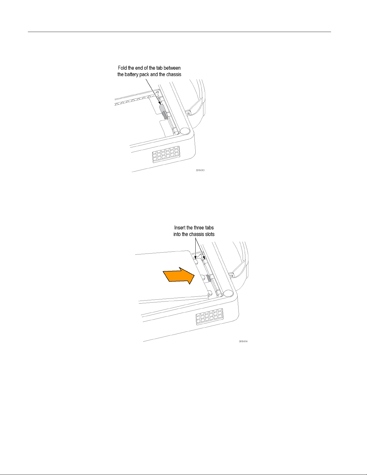
3. Secure the batt
4. Replace the battery compartment cover:
a. Insert the three tabs on the battery cover into the chassis slots as shown
below.
ery pack tab as shown below.
10 WFM2200 Waveform Monitor & Generator User Manual
Page 27

Getting started
b. Close the batte
to secure the cover.
c. Press the batt
below.
ry cover and turn the battery cover ring ¼ turn clockwise
ery cover ring down so that it latches into place as shown
WFM2200 Waveform Monitor & Generator User Manual 11
Page 28

Getting started
Power-on and power-off
procedures
This section pr
Power-on procedure. Perform the following steps to power on the instrument:
1. Connect power to the instrument:
AC adapter. C
Battery pac
2. Press the S
on.
3. If you are
power level before operating the instrument. (See page 13, Battery charge
level indicators.)
Power-off procedure. Perform the following steps to power off the instrument:
1. Press the Standby button using one of the following two methods:
Press and hold the Standby button for one second and then release to
ovides procedures for powering the instrument on and off.
onnect the AC adapter to the power connector on the
instrument. (See page 8, Power cord installation.)
k. Install the WFM200BA battery pack. (See page 9, Battery
pack installation.)
tandby button on the instrument front panel to turn the instrument
powering the instrument using only the battery pack, check the
put the instrument in Standby mode. In Standby mode, the instrument
consumes less power than when it is turned on and also takes less time to
turn back on than when it is turned completely off. The Standby button
ins illuminated when the instrument is in Standby mode.
rema
Press and hold the Standby button for four seconds and then release to
n the instrument off.
tur
NOTE. When you press and hold the Standby button, a message box appears
stating how long to hold the button for Standby mode or to turn the instrument
off. To turn the instrument off, hold the button until the message “Release the
POWER button to power off now” is displayed.
2. To remove power completely from the instrument, disconnect the AC adapter
from the power connector and remove any installed battery pack.
12 WFM2200 Waveform Monitor & Generator User Manual
Page 29

Getting started
Battery charge
level indicators. When the WFM200BA battery pack is not
installed in the instrument, you can check the charge level by pressing the Check
button on the back of the battery pack. LEDs will illuminate to indicate the
amount of charge remaining in increments of approximately 20%.
When a bat
tery pack is installed in the instrument, the charge level meter is shown
on the bottom right of the status bar. The following table shows examples of the
meter icons.
Table 6: Battery charge-level meter icons
Item Description
Battery fully charged, AC adapter plugged in
Battery partially charged, AC adapter plugged in and charging
Battery level low, AC adapter not plugged in
Battery level critically low, AC adapter not plugged in
WFM2200 Waveform Monitor & Generator User Manual 13
Page 30
Getting started
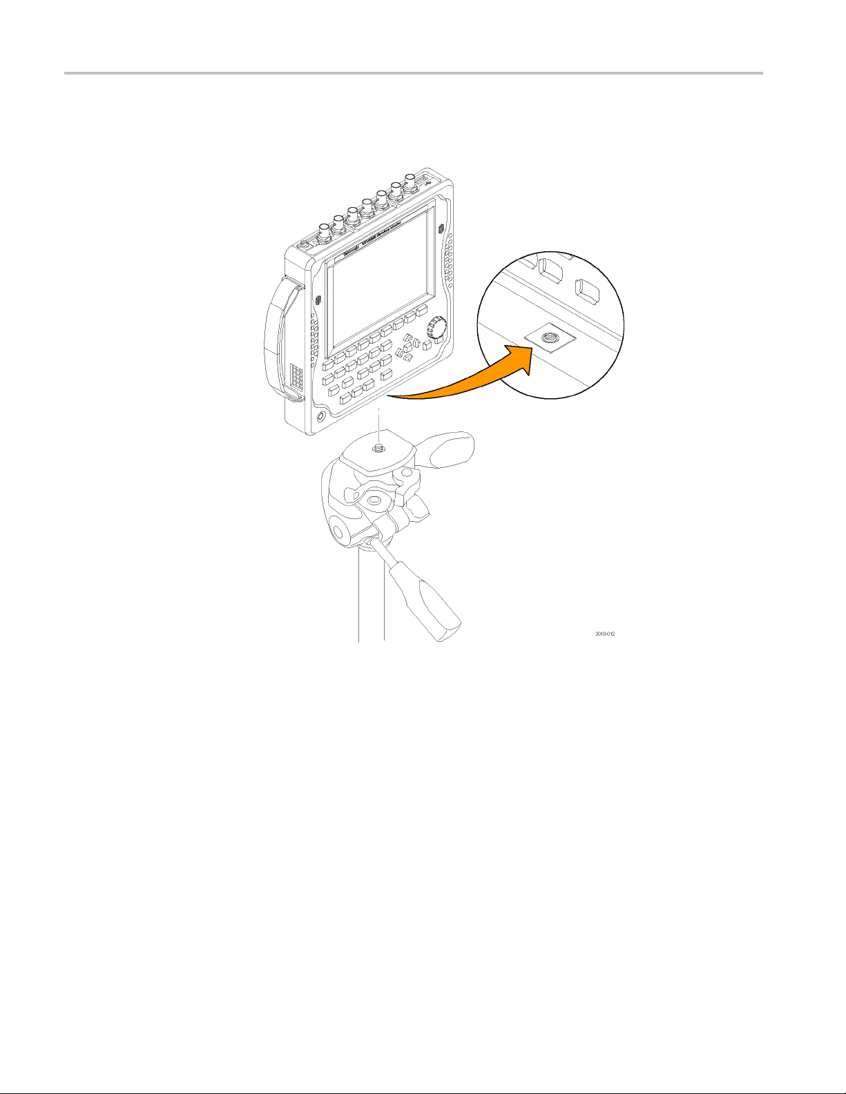
Tripod installation
The bottom pane
instrument on a camera tripod as shown below.
l provides a ¼-20 threaded hole that can be used to mount the
nstrument can operate almost anywhere in the distribution system where
Video system installation
14 WFM2200 Waveform Monitor & Generator User Manual
The i
serial digital system monitoring is needed.
Line termination. The video inputs (SDI A, SDI B, and REF IN) each have 75 Ω
internal terminations.
mpatibility of BNC center pins. Most BNC connectors for video equipment,
Co
whether 50 Ω or 75 Ω,usea50Ω standard center pin. Some laboratory 75 Ω
BNC connectors use a smaller diameter center pin. The BNC connectors on the
instrument are designed to work with the 50 Ω standard (large diameter) center
pins.
Do not use connectors or terminators with the smaller center pins. They could
cause intermittent connections.
Page 31
Getting started
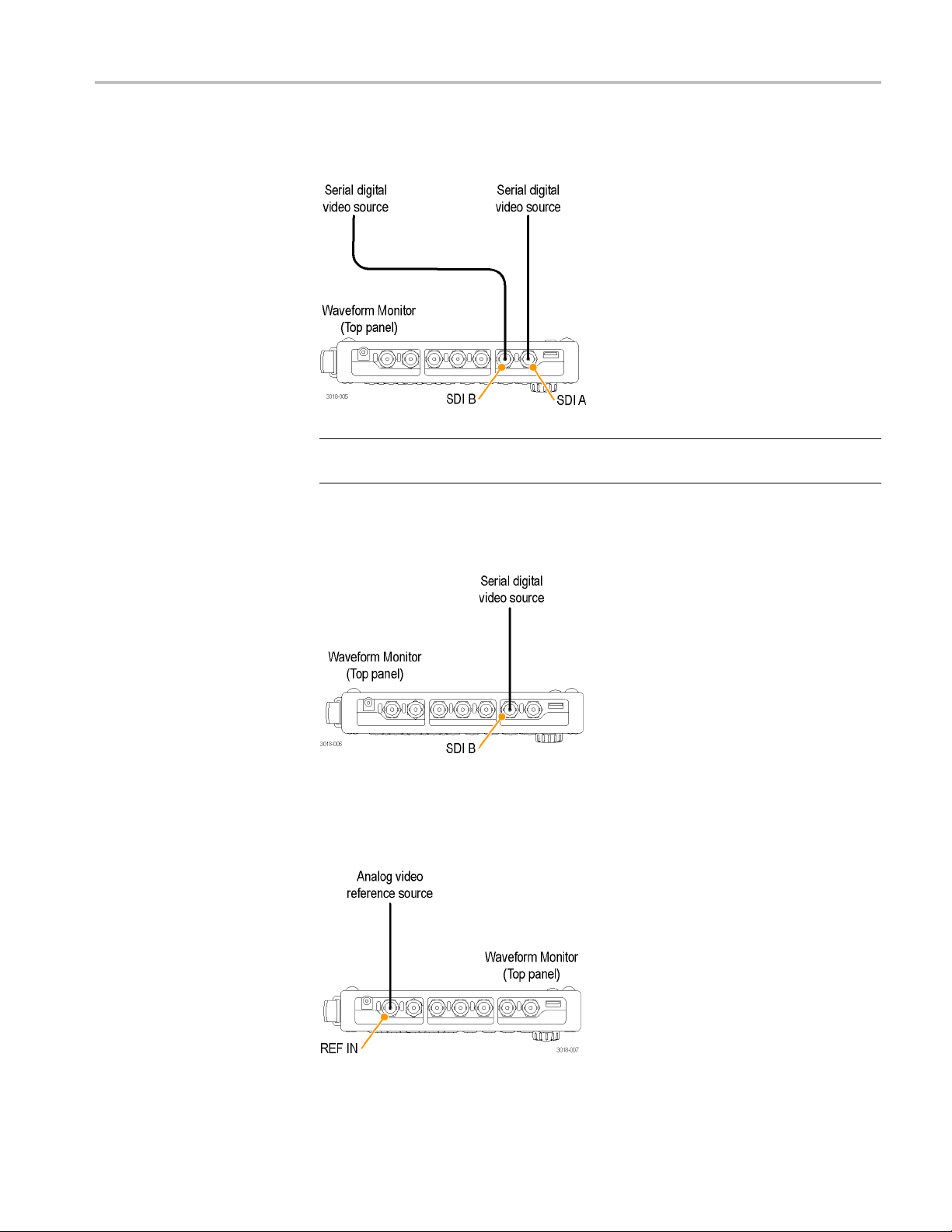
Monitoring the
serial signals into the SDI inputs on the instrument.
NOTE. See the WFM2200 Specifications and Performance Verification Technical
Referenc
Monitoring the embedded audio signal in a serial digital video stream. Route the
incomin
video bit stream of a serial receiver. Route one or more incoming
e for the maximum allowed cable lengths.
g serial signal into one of the SDI inputs on the instrument.
Monitoring the external reference signal. Route the incoming reference signal into
the REF IN input on the instrument.
WFM2200 Waveform Monitor & Generator User Manual 15
Page 32

Getting started
Configure the n
etwork interface
Configure the IP address
An Ethernet connection to the instrument is required for some instrument
functions such as the following:
Accessing the remote interface of the instrument
Remotely controlling the instrument using SNMP commands
Upgrading the instrument software
Perform th
1. Make one of the following Ethernet connections:
2. Press
3. Assign the instrument an IP address:
efollowingstepstoconfigure the IP address of the instrument:
If you have a local Ethernet network, connect the instrument and computer
to the network.
If you do not have a local Ethernet network, connect the computer
directly to the instrument using an Ethernet cable. The instrument has an
rossover feature, so you do not need a crossover cable. You can also
auto-c
use a network HUB connection between the PC and the instrument.
the Standby button to power on the instrument.
. When the instrument is connected to your local network, the instrum ent
NOTE
must be assigned a valid IP address to operate on your network. The instrument is
shipped with a default IP address of 192.168.1.1, but the address will usually not
be valid on your local network.
The network addresses of the instrument can be assigned either manually or
automatically using DHCP. If your network does not use DHCP, you will have to
manually enter the address for the instrument. In that case, contact your local
LAN administrator to obtain the valid network addresses.
Alternatively, when you connect the computer directly to the instrument using an
Ethernet cable, you can manually assign the instrument any IP address that is
compatible with the IP address for the Ethernet interface of the computer.
a. Press the CONFIG button on the front panel.
b. Navigate to Network Settings > IP ConfigMode.
16 WFM2200 Waveform Monitor & Generator User Manual
Page 33

Getting started
c. Set the IP config
If you connected the instrument to your local network, select either
Manual or DHCP
If you connected the instrument directly to your computer, select
Manual.
d. If you set the IP configuration mode to Manual, perform one of the
following t
If you connected the instrument to your local Ethernet network, enter
the IP addr
LAN administrator.
If you con
IP address that is compatible with the IP address for the Ethernet
interface of the computer. For example, if the IP address of the
computer is 199.55.142.12, then set the IP address of the instrument to
199.55.142.x, where x ≠ 0, 12, or 255.
Set the subnet mask to the same value used by the computer. Set the
gateway address to be the address of the computer.
NOTE. If you selected DHCP mode, the network automatically assigns the
rument an IP address. DHCP typically requires several seconds to assign
inst
the network address.
uration mode:
as directed by your LAN administrator.
asks:
ess, s ubnet mask, and gateway address as directed by your
nected the instrument directly to your computer, enter an
e. Press the CONFIG button on the front p anel to close the menus.
WFM2200 Waveform Monitor & Generator User Manual 17
Page 34

Getting started
Enable the Web remote
interface
Before you can a
interface of the instrument must be enabled. Optionally, you can create a
password which would then be required to gain access to the instrument using a
Web b row ser.
NOTE. The instrument is shipped with the Web remote interface disabled and no
passwordrequiredtogainaccesstotheinstrumentusingaWebbrowser.
Perform the following steps to enable the Web remote interface:
1. Press the CONFIG button.
2. Navigate to Network Settings > Web Enable.
3. Select On to enable the Web remote interface.
4. To c rea t
instrument using a Web browser, perform the following steps:
a. Naviga
menu focus to the submenu. This opens the Web Password display.
b. Use th
the password. Use the up/down arrow keys or the knob to change the
text in each box as required.
ccess the instrument using a Web browser, the Web remote
eapasswordthatwouldberequiredtogainremoteaccesstothe
te to Web Password and press the right-arrow key to change the
e left/right arrow keys to move the highlight to the desired box in
c. To accept, clear, or cancel your changes, move the highlight to the
respective selection box and press the SEL button.
5. Press the CONFIG button on the front panel to close the menu d isplay.
18 WFM2200 Waveform Monitor & Generator User Manual
Page 35

Getting started
Configure an d enable
SNMP control
If you intend to
control is primarily intended for access through automation systems), you must
enable SNMP and configure the SNMP parameters of the instrument.
NOTE. The wfm_mon.mib and wfm2200.mib files contain the SNMP OIDs for the
WFM2200 waveform monitor. These files can be downloaded from the home page
of the Web remote interface.
Perform the following steps to configure and enable SNMP control:
1. Press the CONFIG button and navigate to the Network Settings submenu.
2. Set the Public Community string as follows. This string is effectively a
password and is required before SNMP commands can read values from the
instrument. The default string value is “public”.
a. Navigate to SNMP Public Community, and then press the right arrow
key to open the SNMP Public Community edit box.
b. Use the left and right arrow keys to move the highlight to each box in the
string. For each box in the string, use the up and down arrow keys to
change the entry as required for your installation.
c. To accept, clear, or cancel the changes, select the appropriate selection
box and press the SEL button.
use SNMP commands to remotely control the instrument (SNMP
3. Set the Private Community string as follows. This string is effectively a
password and is required before SNMP commands can read or write changes
o the instrument. The default string value is “private”.
int
a. Navigate to SNMP Private Community, and then press the right arrow
y to open the SNMP Private Community edit box.
ke
b. Use the left and right arrow keys to move the highlight to each box in the
tring. For each box in the string, use the up and down arrow keys to
s
change the entry as required for your installation.
o accept, clear, or cancel the changes, select the appropriate selection
c.T
box and press the SEL button.
WFM2200 Waveform Monitor & Generator User Manual 19
Page 36

Getting started
4. Set the SNMP tra
addresses to which SNMP traps are sent through SNMP when error conditions
are detected.
NOTE. The default value for the SNMP trap addresses is all zeroes, which
disables the trap outputs.
a. Navigate to SNMP Trap Address 1, and then press the right arrow key to
open the SNMP Trap Address edit box.
b. Use the left and right arrow keys to move the highlight to each box in the
address. For each box in the address, use the up and down arrow keys to
change the entry as required for your installation.
c. To accept, clear, or cancel the changes, select the appropriate selection
box and press the SEL button.
d. Repeat steps a through c for the other three SNMP trap addresses as
required for your installation.
5. Navigate to SNMP Enable and press the right arrow key to select On.This
setting turns SNMP remote access to the instrument on and off.
6. Navigate to SNMP Trap Enable and press the right arrow key to select On.
This setting turns the traps that are sent out from the instrument through
SNMP on and off.
p addresses as follows. You can configure up to four IP
7. Press the CONFIG button on the front panel to close the menu d isplay.
20 WFM2200 Waveform Monitor & Generator User Manual
Page 37

Incoming inspection
Getting started
The incoming inspection procedures are basic optional procedures to check the
functionality of your instrument. These procedures require no external equipment.
For a more robust inspection, see the performance verificationproceduresinthe
WFM2200 Specifications and Performance Verification Technical Reference.
Basic turn on and self test
Front panel test
1. Connect power to the instrument. (See page 8, Connect power.)
2. Turn the in
3. After about 30 seconds, the power-on diagnostic page should appear on the
screen.
4. Verify that all self tests pass. Any failures are shown in red.
NOTE. Al
screen during the power-on process, you can view the results by selecting
CONFIG > Utilities > View Diagnostics Log > SEL or by viewing them on the
instrument Web page.
5. After the diagnostics are finished, the instrument state is restored. When the
progress indicator in the status bar is finished, the instrument has finished
initializing.
1. Reset the instrument settings to the Factory Presets:
a. Press and hold the PRESET button to open the Preset menu.
b. Select Recall Preset > Recall Factory Preset, and then press the SEL
bu
indicator.
strument on. (See page 12, Power-on procedure.)
though the results of the power-on diagnostics are erased from the
tton. Wait for the process to complete as indicated by the progress
ress the HELP button to display the online help.
2.P
3. Press each of the front panel buttons, one at a time, except for the Standby
button and the HELP button.
Each button should flash as you press it.
4. Press the right arrow key until the Help Contents pane in the upper-left corner
is highlighted.
5. Turn the knob and verify that the selector box moves up and down the list
of topics.
6. Press the HELP button to exit the online help.
WFM2200 Waveform Monitor & Generator User Manual 21
Page 38

Getting started
Fan test
1. You should be ab
instrument. At low temperatures, the fans will turn slowly and be very quiet.
2. Press and hold
3. UsethearrowkeystoselectDisplay Type > Diag Monitor to open the
Diagnostic
4. If necessary, use the up and dow n arrow keys to view Page 1 of 4 of the
display. Th
5. The fan speed in rpm (revolutions per minute) is shown at the top of the
display fo
r each of the two internal fans. The fan speeds should be fairly equal.
le to hear the fans and feel air coming out of the back of the
the GEN button to open the Generator pop-up menu.
s Monitor display.
e page number is located in the upper right corner of the display.
22 WFM2200 Waveform Monitor & Generator User Manual
Page 39

Getting started
Storing or shi
pping the instrument
To repackage the Li-Ion
battery pack for sh ipment
To repackage the
instrument for shipment
CAUTION. To prevent damage to the Li-Ion battery pack and the instrument,
observe the following precautions when storing or shipping the instrument:
■ Do not store the battery pack in the instrument when the instrument is not in use.
■ Remove the battery pack before shipping the instrument.
See the WFM200BA Rechargeable Battery Pack Instructions that was supplied
with the battery pack for information about handling, storing, shipping, and
recycling Li-Ion battery packs.
CAUTION. To prevent dam
packaging when shipping the battery pack and ensure that the package labeling
and documentation meets all of the requirements for shipping Li-Ion batteries
under the IATA Dangerous Goods Regulations.
Use the following instructions to prepare your instrument for shipment to a
Tektronix, Inc., Service Center:
age to the Li-Ion battery pack, use the original
CAUTION. Remove the battery pack when transporting or storing the instrument
in an enclosed container.
1. Attach a tag to the instrument showing: the owner, complete address and
phone number of someone at your firm who can be contacted, the instrument
serial number, and a description of the required service.
2. Package the instrument in the original packaging materia ls. You can contact
Tektronix to obtain replacement packaging.
If you cannot use the original packaging materials to package the instrument,
follow these directions:
a. Obtain a carton of corrugated cardboard h
more inches greater than the dimensions of the instrument. Use a shipping
carton that has a test strength of at least 250 pounds (113.5 kg).
b. Surround the module with a protective (anti-static) bag.
c. Pack dunnage or urethane form between the instrument and the carton.
If using Styrofoam kernels, over fi ll the box and compress the kernels by
closing the lid. There should be three inches of tightly packed cushioning
on all sides of the instrument.
3. Seal the carton with shipping tape, industrial stapler, or both.
aving inside dimensions six or
WFM2200 Waveform Monitor & Generator User Manual 23
Page 40

Getting started
24 WFM2200 Waveform Monitor & Generator User Manual
Page 41

Getting acquainted with your instrument
Front-panel c
Three leve
ls of control
ontrols
NOTE. Some of the controls that are covered in this section are option-dependent.
For a list of the options that are installed on your instrument, press the CONFIG
button. In the Configuration menu, select the Utilities submenu. The View
Instrument Options entry lists the options installed on your instrument.
You control the instrument on three levels:
Frequently changed settings. The front panel buttons control the most
commonly changed parameters, such as which measurement appears in each
tile. Use the knob and navigation buttons to adjust levels and make selections.
pecific settings. Pop-up menus control parameters that are specificto
Tile-s
the tile in which they are displayed. The pop-up menus control less frequently
changed parameters such as the waveform display mode (for example,
changing the waveform display mode from RGB to YPbPr). To display a
pop-up menu, press and hold the desired button for about two seconds.
Instrument-wide settings. The parameters in the Configuration menu are
instrument-wide settings. The configuration menu controls settings that are
changed only occasionally, such as changing waveform color or setting the
work address.
net
Scope of controls
Some controls are global and affect all tiles, while other controls only affect the
active tile. Generally speaking, if a control is configured by front panel buttons or
a pop-up menu, it is tile specific. (Exceptions are the Input and Ref buttons,
by
and all audio and generator features, each of which are global.)
f a control is configuredbytheConfiguration menu, the selections are always
I
global. The settings in the Display, Main, and Preset menus are also global.
The Capture button can be either global or tile specific depending on the setting in
the Configuration menu (Display Settings > Freeze Affects).
WFM2200 Waveform Monitor & Generator User Manual 25
Page 42
Getting acquainted with your instrument
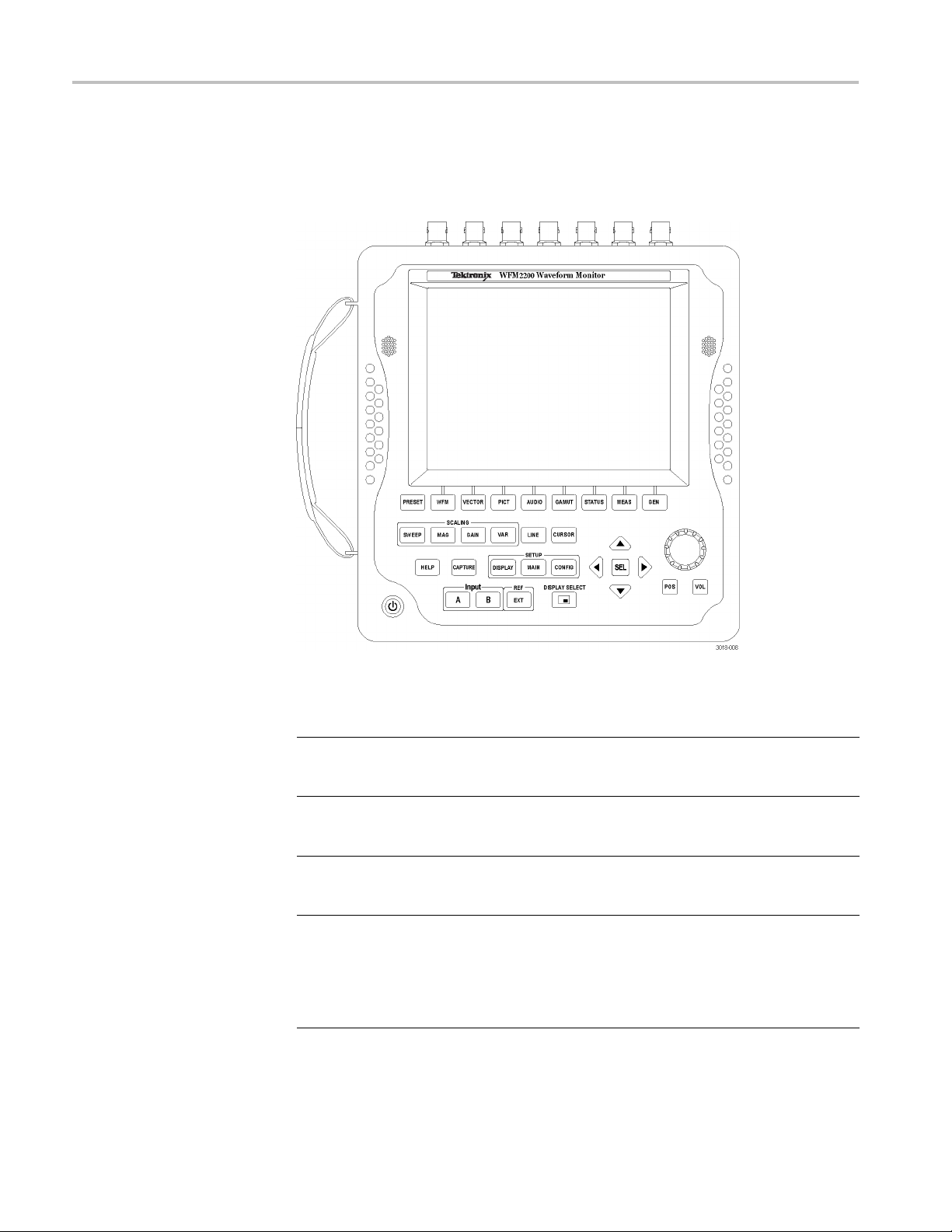
Layout and usage
The primary fro
nt panel elements shown below are described in the table that
follows. The Description / usage procedure column in the table refers you to a
procedure in this manual that explains how to use the element. If there is no page
reference, the information given explains the basic function of the element.
Control element or group Description / usage procedure
Preset button Press to save or recall presets using the bezel
buttons. Press and hold to access the Preset
menu. (See page 125, Presets.)
Measurement buttons
(WFM, VECTOR, PICT, AUDIO,
GAMUT, STATUS, M EAS , GEN)
Scaling buttons
(SWEEP, MAG, GAIN, VAR)
Line Select button
Press these buttons to select one of the
instrument displays.
(See page 30, To select a display.)
Press these buttons to select how the signal
trace is displayed.
(See page 115, Gain, sweep, and magnification.)
Press the LINE button to enable or disable
the Line Select mode. When enabled, use the
General knob and arrow buttons to select which
line and field to display. In the Datalist display,
press the SEL button to toggle between line and
sample select. (See page 122, Line select.)
26 WFM2200 Waveform Monitor & Generator User Manual
Page 43

Getting acquainted with your instrument
Control element or group Description / usage procedure
CURSOR button
HELP button Press this button to display context-sensitive
CAPTURE button Press this button to capture an image of the
Setup bu
(DISPLAY, MAIN, CONFIG)
Input selection buttons
(INPUT A, IN PU T B)
EXT REF button Press this button to toggle the synchronization
ttons
Press this but
measurement cursors. When enabled, use the
General knob and the arrow buttons to adjust
the cursor pos
the Cursor pop-up menu. (See page 119,
Measurement cursors (Waveform display only).)
online help for the selected display mode or
menu item. U
buttons to navigate the online help content.
When online help is displayed, you can press
most of the
information about those buttons. (See page 29,
To navigate online help.)
selected
Capture pop-up menu where you can compare
a captured display image with the live display.
(See page
Press th
selections to adjust various display levels, to
enable the Infinite Persistence mode, and to
save a co
connected to the USB port.
Press the MAIN button to access menu
select
check the USB port status, and to configure the
function of the Display Select button (selecting a
ay or turning the Thumbnail view on/off).
displ
Press the CONFIG button to access menu
selections to configure various instrument
param
set network parameters, to perform a system
upgrade, and more.
Press these buttons to select which video input
to monitor: SDI A or SDI B.
page 37, Signal inputs and outputs.)
(See
rce between the internal reference signal or
sou
the analog video reference signal connected to
the REF IN input. (See page 15, Monitoring the
ernal reference signal.)
ext
(See page 178, Timing a studio.)
ton to enable or disable the
itions. Press and hold to access
se the General knob and the arrow
front panel buttons to access
display. Press and hold to access the
121, Display capture (freeze).)
e DISPLAY button to access menu
py of the instrument display to a device
ions to select the tile display mode, to
eters, to check for installed options, to
WFM2200 Waveform Monitor & Generator User Manual 27
Page 44

Getting acquainted with your instrument
Control element or group Description / usage procedure
DISPLAY SELECT / Thumbnail button Press this button to move the tile selection from
Arrow keys a
General k
Position button
e button
Volum
nd SEL button
nob
one tile to another. Press and hold to toggle
between Full S
The default setting for this button is as a tile
select button. You can configure this button
using the MAI
thumbnail view of the picture on and off in the
selected tile. The position of the thumbnail is
determined
Press the up
navigate between menu panes and selections
or to increment/decrement values. Press the
SEL button
Turn the G
parameter and to navigate through a menu
or online help. When the General knob is
enabled,
enabled parameter to indicate which parameter
is controlled by the knob.
Press the POS button, and then use the General
knob to
Vector, Lightning, and Bowtie displays. Use the
up/down arrow buttons for finer adjustments
and use
between horizontal and vertical adjustments.
Press the VOL button, and then use the General
knob and the up/down arrow buttons to adjust
lume. When the Audio tile is selected and
the vo
no menus are active, the General knob controls
the volume.
monitoring high-amplitude audio, volume
When
levels over 90% may cause audio clipping.
creen and 4-Tile display modes.
N button menu to toggle the
automatically.
/down/left/right arrow keys to
to set the selected parameter.
eneral knob to select or adjust a
a knob icon appears next to the
position traces on the Waveform,
the left/right arrow buttons to switch
WAR NI NG . To prevent risk of hearing
age, always turn down the headphone
dam
audio level before connecting a headphone
into the headphone jack. Sound levels and
edance can vary between headphones.
imp
andby (power) button
St
en the instrument is in Standby mode or
Wh
turned off, press the Standby button to turn the
instrument on.
en the instrument is on, press and hold
Wh
the Standby button to put the instrument in
Standby mode or to turn the instrument off. (See
age 12, Power-on and power-off procedures.)
p
NOTE. The Standby button does not remove
power from the instrument.
28 WFM2200 Waveform Monitor & Generator User Manual
Page 45

Online help
Getting acquainted with your instrument
Press the HELP button to access the instrument online help. (See Figure 1.) Use
the online help when you have questions about buttons, features, or operations
related to yo
Context-sensitive. The topic displayed depends on what is displayed in the
active tile when the online help is selected or what control is operated after
help is selected.
Navigable. The Contents and Topic Selector panes, with links within the
topics, provide access to topics.
ur instrument. The online help is:
Figure 1: Instrument online help
To navigate online help
WFM2200 Waveform Monitor & Generator User Manual 29
1. Press the HELP buttontoopenonlinehelp.
2. Press the right arrow key to navigate to the one of the three panes: Help
Contents, Help Index, or the right-side pane that contains the topic content
related to the front panel button you press while help is activated or the links
in the help files and menus you use.
3. Use the General knob or the up/down arrow keys to highlight an entry in
the Contents (entries never change) or the Index, or to highlight a link in
the topic pane.
4. Press the SEL button to select the highlighted item.
5. Press the HELP button again to exit online help.
Page 46

Getting acquainted with your instrument
Instrument display
This instrument uses Quad Tile, which is a flexible, four-tiled display that can
show four tiles at one time or a single, full-screen sized tile. The instrument also
provides the flexibility to configure each of the four display tiles independently,
enabling you to quickly check the integrity of a signal.
Supported d
isplays
This instrument supports the displays listed below. For detailed information about
each of the displays, see Display modes. (Seepage42.)
NOTE. Some displays require a specific option to be installed. For example, the
ANC Data d
Options and optional accessories.)
Waveform: YPbPr, YRGB, RGB, SDI → Composite or XYZ
Vect or : N o r m a l , S D I → Composite, Lightning
Gamut: Arrowhead, Diamond, Split Diamond
Measure: Timing, Datalist, Bowtie, ANC Data
Status: Error Log, Alarm Status, Video Session, Audio Session, Dolby Status,
Audio Control, AES Channel Status, Auxiliary Data Status
Audio: Phase, Surround
Pict
graticules
Gen
isplay is not accessible unless you have Option DATA. (See page 4,
ure: Picture frame (on/off) and various closed caption and safe area
erator: Generator Status, Diagnostics Monitor
To select a display
30 WFM2200 Waveform Monitor & Generator User Manual
Push a front panel button corresponding to the display that you want to view and
one of the following selected displays will appear:
WFM: display of video waveform, Longitudinal Time Code (LTC) waveform,
or External Reference waveform
VECTOR: display of vector and lightning plots of color signals
PICT: display of the picture generated by the video signal
AUDIO: display of levels (meters), phase (plot), and surround sound for
monitoring audio signals
GAMUT: display of one of four views for checking the gamut of an SDI
signal
STATUS: display of extensive views of signal status
Page 47

Getting acquainted with your instrument
Pop-up menus
To set display parameters
MEAS:displayo
delay, ANC data, and Data List
GEN:displayo
signal generators or information from the Diagnostics Monitor
All pop-up menus are displayed by pressing and holding the specified display
button for t
Pop-up menus appear in the active tile and, in general, control only settings
specific that tile. A pop-up menu will not appear if it is not appropriate for the
current instrument setting.
Use the pop-up menus to set up the measurements that you display.
1. Select a
2. Press and hold a display button and the display and the pop-up menu for
that di
NOTE. The selections in a pop-up menu can change depending on settings.
hree seconds. To hide a pop-up menu, press the specified button again.
tile by pressing the Display Select button.
splay appears.
f various measurements, including timing, audio video
f status and configuration of the SDI video and AES audio test
3. Use t
4. Use t
Figure 2: Navigate menus using the arrow keys and select button
5. Navigate through the menu and make your selections.
he right and left keys to move between menu panels. The instrument
surrounds the panel selected with a blue border.
he up and down arrow keys to select parameters in a menu. (See
Figure 2.)
WFM2200 Waveform Monitor & Generator User Manual 31
Page 48

Getting acquainted with your instrument
DISPLAY SELECT button
You can configur
following two modes:
Tile selectio
from 4-tile to full-screen mode and back again.
Thumbnail v
the Waveform, Vector, or Gamut displays. The Waveform, Vector, or Gamut
display must be in full-screen mode to activate the thumbnail view.
Button configuration. Perform the following steps to configure the function of the
DISPLAY SELECT button:
1. Press the MAIN button to display the Main menu.
2. Navigate to Display Select.
3. Press the right arrow key to select Thumb or Tile Sel.
4. Press the MAIN button to close the Main menu.
Tile selection mode. When the DISPLAY SELECT button is configured for tile
selection, the button functions as follows:
In 4-tile mode, press the DISPLAY SELECT button to move the active tile
selection to the next tile. The selected (active) tile is outlined in blue. The tile
numbers and their associated quadrants are shown below.
e the DISPLAY SELECT button to function in one of the
n. Select one of the four tiles while in 4-tile mode and change
iew. Toggle on or off the thumbnail view of the picture display in
Figure 3: Display quadrants and related tile numbers
32 WFM2200 Waveform Monitor & Generator User Manual
Page 49
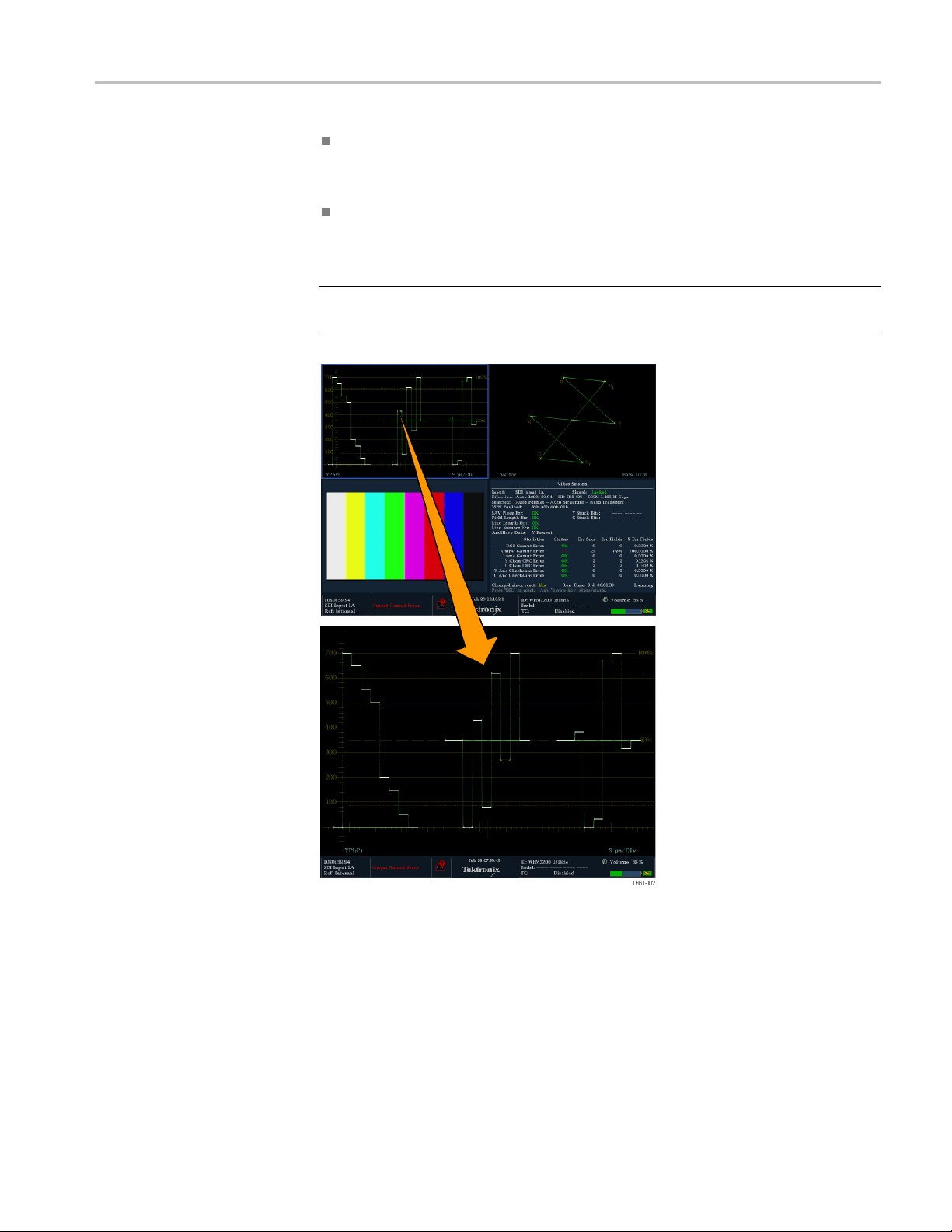
Getting acquainted with your instrument
In full screen m
display to the next tile. In full screen mode, the same four displays are
available as in 4-tile mode.
Press and hold the DISPLAY SELECT button to toggle between 4-tile and
full screen mode. The selected (active) tile in 4-tile mode is the tile expanded
to full screen mode. (See Figure 4.)
NOTE. You can also use the Main menu to toggle between 4-tile and full screen
mode and to select the active tile.
ode, press the DISPLAY SELECT button to change the
Figure 4: Changing from 4-tile to full-screen view
WFM2200 Waveform Monitor & Generator User Manual 33
Page 50

Getting acquainted with your instrument
Thumbnail view
Thumbnail view and the thumbnail view is enabled, the button functions as
follows:
NOTE. When the Display Select setting is set to Thumbnail in the Main menu,
pressing the DISPLAY SELECT button will toggle the thumbnail view on and
off. This is equivalent to toggling the CONFIG > Display Settings > Thumbnail
setting.
The thumbnail view is not shown when the Picture display is visible in any tile.
In full screen or 4-tile mode with no Picture d isplay in any tile, press the
DISPLAY SELECT button to toggle the thumbnail view of the picture display
on and of
In 4-tile mode, the placement of the thumbnail view is determined
automat
containing a trace display, and then on status displays.
The fol
view enabled. In full screen mode, the thumbnail is always positioned in the
lower right region of the display.
lowing figure shows a full screen Waveform display with the thumbnail
mode. When the DISPLAY SELECT button is configured for
f. The button stays illuminated when the thumbnail view is turned on.
ically. However, the placement is usually in the highest numbered tile
Figure 5: Thumbnail view in Waveform display
34 WFM2200 Waveform Monitor & Generator User Manual
Page 51

Getting acquainted with your instrument
Status bar
The Status bar i
instrument status, the type of signal being monitored, some alarms associated with
that signal, and other information. (See Figure 6.)
Figure 6 : Elements of the Status bar
Status display
element Description
Input format Text indicating the format of the signal or whether the signal is missing
Current input Text indicating the selected SDI input:
s located on the bottom of the instrument display and shows
of unlocked.
1A or 1B for standard SDI signals
1DL for dual link signals
Reference source Text indicating the source of the current reference. When the reference
source is set to internal, “Internal” is always displayed. When the
reference source is set to external, the text indicates the reference
format (such as NTSC) or whether the reference is m issing or unlocked.
EDH and gamut
alarm/error
readouts
Alarm/error icon
indicator
Date and time
Readouts indicating that EDH or gamut errors are present. The
following readouts appear only if the alarms have been enabled for
screen text/icon notification in the CONFIG menu:
EDH Error: This readout appears when EDH errors are present.
RGB Gamut Error: This readout appears when RGB gamut errors
are present.
Cmpst Gamut Error: This readout appears when Composite gamut
(Arrowhead) errors are present.
RGB and Cmpst Gamut: This readout appears when both RGB
and Composite Gamut errors are present at the same time.
Luma Gamut Error: This readout appears when Luma errors are
present.
An icon that appears when alarms that have been configured for screen
text/icon notification in the CONFIG menu occur. The icon will also
appear when alarms are active but have been muted or disabled.
A readout of the instrument date and time (set in CONFIG > Utilities).
WFM2200 Waveform Monitor & Generator User Manual 35
Page 52

Getting acquainted with your instrument
Status display
element Description
Instrument name
Audio status
Timecode readout
Audio volu
Battery level
meter
AC status An icon that indicates whether the AC adapter is plugged in and/or
me
A readout showing the name assigned to the instrument in the CONFIG
> Network Sett
An up to 32-ch
or the embedded audio channel status, when embedded audio is the
selected input. In the latter case, each character shows the status of a
specificcha
A readout sh
time code is disabled.
A readout showing the audio volume setting in the CONFIG > Audio
Inputs/Outputs menu.
When a battery pack is installed, a meter showing the battery charge
level is displayed. (See page 13, Battery charge level indicators.)
g the battery pack. (See page 13, Battery charge level
chargin
indicators.)
ings menu.
aracter string indicating the selected audio input (AES A)
nnel: – for not present and P for present.
owing the selected time-code value. Also indicates if the
Status bar icons. The following table describes the Status bar icons.
Icon Description
Warning - Appears when an error or an alarm that is mapped to the user
interface triggers.
Alarms Muted - Appears when the alarms are muted from the STATUS pop-up
menu.
Remote Access - Appears when the instrument is accessed from the network.
For example, when sending commands to the instrument from the remote
interface.
Alarms Disabled - This text appears in the Status Bar when Alarms are disabled
from the Configuration menu.
Freeze Active - Appears when the tiles are frozen or captured.
Battery Low - This icon appears only w hen the instrument is using a battery
pack as the power source. This icon appears when the battery has less than
10 minutes of operating power remaining. The icon turns from yellow to red
when instrument shutdown is imminent due to low battery power.
36 WFM2200 Waveform Monitor & Generator User Manual
Page 53

Signal inputs and outputs
Signal inputs
Connectors
Signal inputs
SDI signals
and outputs
See the WFM2
product for descriptions of the connector functions.
See the WFM2
Reference for the complete connector specifications.
Both docu
www.tektronix.com/downloads.
Connect one or more 3G-SDI, HD-SDI, or SD-SDI signals to the SDI inputs on
the top panel of the instrument. (See page 14, Video system installation.)
Use the CONFIG menu to set the parameters for monitoring the s ignals, such as
thresholds, alarms monitored, and audio source.
200 Installation and Safety Instructions that shipped with your
200 Specifications and Performance Verification Technical
ments a re available in electronic format on the Tektronix Web site at
External reference signals
ference input is internally terminated in 75 Ω. Reference signals can be
The re
analog video Black Burst or Tri-level sync.
r you connect the appropriate reference signal to the EXT REF connector,
Afte
press the EXT REF button to change the signal reference to external. The EXT
button illuminates when External reference is selected. (See page 14, Vi deo
system installation.)
You can select which signal format to lock to by pressing the CONFIG button
and selecting External Ref. The default setting is Auto.
View the reference signal. You can use the waveform display to view the signal
onnected to the EXT REF connector. Press the WFM button to open the
c
waveform display pop-up menu, and then select Display Type > Ref Waveform.
WFM2200 Waveform Monitor & Generator User Manual 37
Page 54

Signal inputs and outputs
Dual link signals
The inputs for d
monitoring allows you to set up your instrument to monitor higher resolution
signals than can be monitored using the traditional single link input. Dual link
signals are combined in the instrument and then shown as a single signal on
a waveform or other display.
The instrument will automatically detect properly formatted dual link signals
which contain a SMPTE352 VPID in both links as required by SMPTE 372.
In this case, set the format, structure, and transport settings in the CONFIG > SDI
Input subm
If the SMPTE352 VPID is missing, the instrument may be forced into dual link
input mod
settings in the CONFIG > SDI Input submenu. Use the Video Session display
(STATUS > Display Type > Video Session) to verify proper configuration.
Alpha Channel information is visible if present and is available in RGB and
YCbCr display modes, but not in YRGB mode. The following figureisan
example of how the signal components appear.
ual link signals are the same as for SDI signals. Dual Link
enu to Auto to enable automatic detection of dual link signals.
e by manually selecting the appropriate sample structure and transport
Figure 7: Placement of dual link information in the Waveform display
38 WFM2200 Waveform Monitor & Generator User Manual
Page 55

Signal inputs and outputs
Connector con
figuration
After you have connected a signal source to your instrument, there are several
menus to use to set up your signal:
CONFIG > SDI Input: select how SDI inputs are displayed. The instrument
can automatically detect the input format, sample structure, and SDI transport
type (or you
You can also choose to not display the EAV, SAV, and ANC data; set chroma
alignment
dual link threshold.
Input A an
signal connected to the SDI A or SDI B input connector. The button for the
selected input (A or B) is illuminated.
When Option 3G is installed and you are monitoring a 2xHD 3 Gb/s SDI
signal (as defined by SMPTE 425), you can press and hold the associated
input button to open a pop-up menu where you can select w hich stream in the
signal to monitor. Possible menu options include the following:
Input 1A (or Input 1B): displays both of the streams in the 2xHD signal.
Input 1A.1 (or Input 1B.1): displays the first stream in the 2xHD signal.
can specify these manually).
; select the NTSC setup level; select HD colorimetry; and set the
d Input B: press the Input A or Input B button to view the video
Input 1A.2 (or Input 1B.2): displays the second stream in the 2xHD signal.
FIG > External Reference: select how the external reference signal is
CON
detected. The instrument can automatically detect the input format or you can
specify which format you want detected.
CONFIG > Outputs and GEN pop-up menu:
r the SDI video output, select the signal type and format, enable moving
Fo
picture mode, and enable embedded audio groups. Option 3G is required
to generate 3 Gb/s SDI signals.
For the AES audio output and for the embedded audio in the SDI video
output, select the frequency, amplitude, and bitdepth.
CONFIG > Audio Inputs/Outputs : select the embedded audio signal
channel, format, and mapping, and set the volume for the instrument speakers
and headphone output.
WFM2200 Waveform Monitor & Generator User Manual 39
Page 56
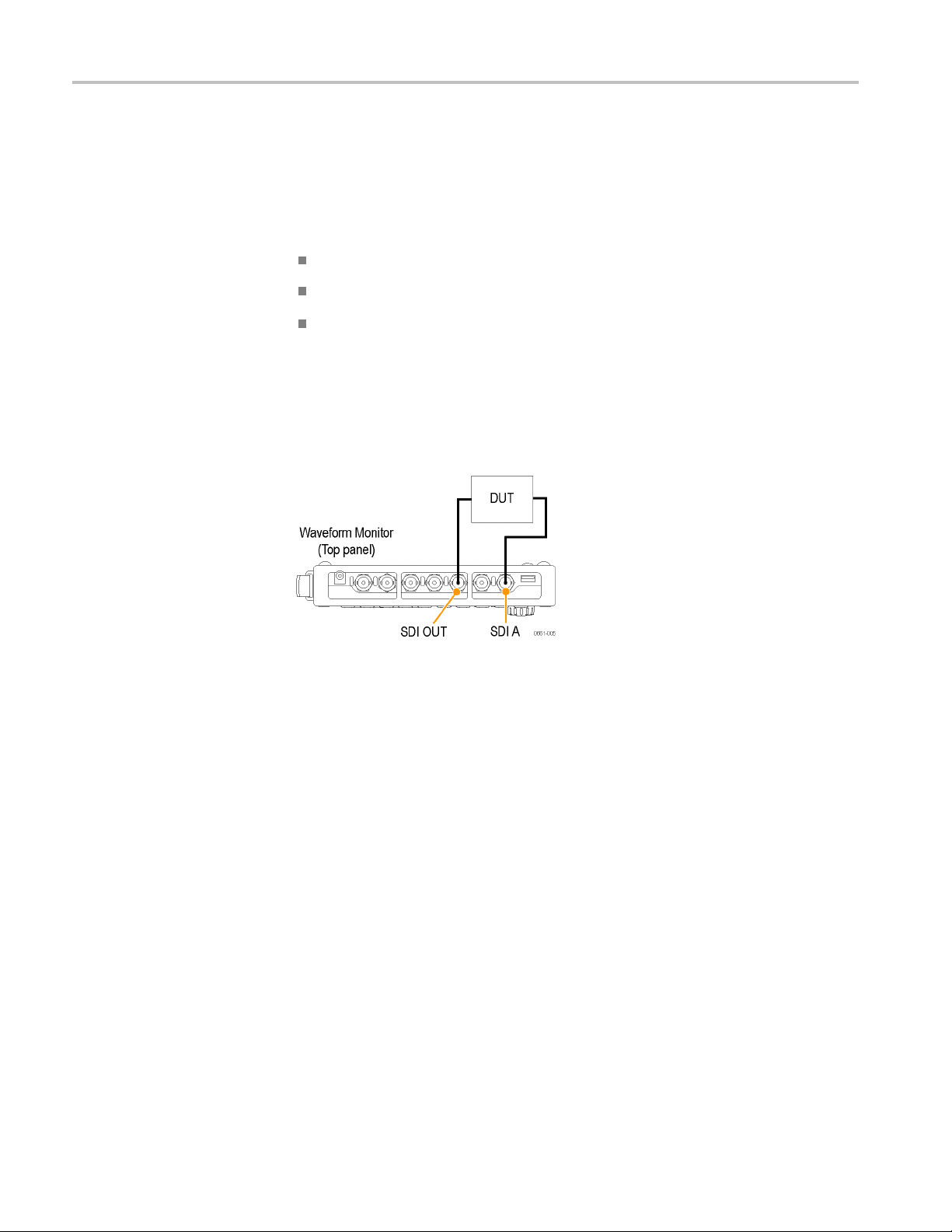
Signal inputs and outputs
Signal output
SDI video output
s
This instrument can generate SD-SDI and HD-SDI signals using the SDI OUT
connector. With Option 3G installed, it can a lso generate a 3 Gb/s SDI test signal.
Three types of signals can be generated in Level A and Level B:
75% bars
100% bars
Pathological
For more i
The following illustration shows signal connections for testing a device. (See
Figure 8
the GEN pop-up menu to select the test signal pattern, level, and format you
want to generate.
nformation about these signals, see the appropriate SMPTE standard.
.) After you connect the signals, use CONFIG > Outputs submenu or
Figure 8: Video signal generation connection
40 WFM2200 Waveform Monitor & Generator User Manual
Page 57

Signal inputs and outputs
AES audio output
This instrumen
Test signal: AES test tones with user-configurable frequency, amplitude, and
bitdepth.
AES loopout: loopthrough output of the signal on the AES IN connector.
Audio output: output of the embedded audio in the video signal being output
on the SDI OUT connector.
The following illustration shows signal connections for testing a device. (See
Figure 9.) After you connect the signals, use CONFIG > Outputs submenu or the
GEN pop-up menu to select the AES audio signal type that you want to generate.
Figure 9: AES audio signal generation connection
t can generate the following AES audio signals:
WFM2200 Waveform Monitor & Generator User Manual 41
Page 58

Display modes
Display modes
This section describes each of the available display modes. The displays are listed
in alphabetical order:
ANC Data display (Option DATA only) –(Seepage43.)
Arrowhead display –(Seepage47.)
Audio display –(Seepage49.)
Bowtie display –(Seepage55.)
Datalist
Diamond display –(Seepage64.)
External Reference Waveform display –(Seepage66.)
Lightning display –(Seepage71.)
LTC Waveform display –(Seepage74.)
Picture display –(Seepage76.)
Split
Status displays:
display (Option DATA only) –(Seepage57.)
Diamond display –(Seepage79.)
AES Channel Status display –(Seepage84.)
Alarm Status display –(Seepage84.)
ARIB status displays –(Seepage85.)
Audio Control status display –(Seepage86.)
dio Session status display – (See page 89.)
Au
Auxiliary Data Status display –(Seepage92.)
Dolby Status display –(Seepage94.)
Error Log status display –(Seepage96.)
Video Session status display –(Seepage99.)
Timing display –(Seepage103.)
Vector display – (See page 107.)
Waveform display –(Seepage111.)
42 WFM2200 Waveform Monitor & Generator User Manual
Page 59

Display modes
ANC Data displ
To access the
ANC Data display
Elements of the
ANC Data display
ay (Option D ATA only)
The ANC (Ancillary) Data d isplay is available only on instruments with Option
DATA installed. This display allows you to more closely examine all of the
ANC data in a s
The ANC Data Inspector is part of the ANC Data display. This ancillary
monitoring feature allows you to see all ancillary data present in a signal. The
instrument continually monitors the signal and tells you when changes in the
presence of data occur.
When Watch List mode is activated, the instrument displays the presence and
status of ANC data types you have selected in the Watch List. This allows you to
focus on the ANC data types that are important to you.
1. Press and hold the MEAS button to open the Measure pop-up menu.
2. Use the arrow keys to select Display Type > ANC Data DISP..
3. Press the MEAS button to close the pop-up menu.
ignal.
Figure 10: ANC Data display (full screen mode)
The ANC Data display includes two sections: (See Figure 19.)
ANC Data Inspector - This section of the display appears both in quad-tile
and full screen display modes. Select a data type in this section to view the
user data in the Detail section.
Detail - This section of the display appears only in full screen mode and
shows the user data for the data type selected in the ANC Data Inspector. You
can expand the Detail area to show more data by pressing the MAG button.
WFM2200 Waveform Monitor & Generator User Manual 43
Page 60

Display modes
The following i
mode:
DID:DataIden
to 0xFF (255) inclusive.
Type:Typeo
equal to 0x80), or Type 2 packet (DID less than 0x80), as definedbySMPTE
291M; Type 1 packets do not have a SDID field, instead they have a DBN
field; the "actual value" (with parity bits added) is displayed in parentheses.
SDID: Secondary Data Identifier of the requested packet; permissible values
range from 0 through 0xFF (255) inclusive; this fieldonlyappearswhen
a Type 2 packet is selected; the "actual value" (with parity bits added) is
displayed in parentheses (mutually exclusive with DBN field).
DBN: Data Block Number of the acquired packet; values range from 0 to
0xFF; the "actual value" (with parity bits added) is displayed in parenthesis
(mutua
DC: Data Count word of the acquired packet; the number of User Data w ords
is dis
in parenthesis, in hexadecimal.
Field
progressive formats, 1 is displayed.
nformation is available on the ANC Data display in full screen
tifier of the requested packet; permissible values range from 1
f the ANC Data packet; either Type 1 packet (DID greater than or
lly exclusive w ith SDID field).
played in decimal; the "actual value" (with parity bits added) is displayed
:Thefield of the video from which the packet was acquired; for
: The line of the video (within the field) from which the packet was
Line
acquired.
eam: For HD (SMPTE 292M), indicates whether the ancillary packet was
Str
acquired from the Y or C data streams; for SD, "N/A" is displayed.
atus: Indicates whether packet(s) of the desired type are present in the
St
video; also indicates Checksum or CRC errors.
hecksum: Indicates the checksum word that was rec ove red from the
C
acquired packet.
Should be: Indicates the checksum work computed by the instrument, based
on data of the packet.
Format: Indicates the name of the ancillary data type or standard.
User Data Words: Contains the payload of the ancillary packet, displayed in
hexadecimal; all 10 bits are displayed.
44 WFM2200 Waveform Monitor & Generator User Manual
Page 61

Display modes
Measure pop-up menu
(ANC Data display)
Press and hold t
menu enables you to configure the display type and configure display parameters
for the different display types. The following menu selections are available:
Display type. Select from the following display types:
Timing - Displays a Tektronix proprietary view that enables y ou to easily
compare and correct the timing between two signals. (See page 103, Timing
Measure display.)
Datalist (Option DATA only) - Displays the content of all digital signal
formats, structures, and transports (SD, HD, 3G, dual link, 4:2:2, 4:4:4, and
others) e
DATA only).)
Bowtie page 55, Bowtie display.)
ANC Dat
signal.
All sessions reset. Select this option and press the SEL button to globally reset
all of the displayed ANC Data display sessions. The session time is set to zero
and all errors (if present) are reset.
he MEAS button to open the Measure pop-up menu. The pop-up
xcept for composite signals. (See page 57, Datalist display (Option
Displays the interchannel timing between Y Pb and Y Pr. (See
a(OptionDATAonly)- Displays all of the ANC data in a video
View mode. Select the view mode:
- Displays all of the ANC data types present in the video signal.
All
Watch list - Displays only the ANC data types selected by the user in the
tch List. (See page 46, To configure the Watch List.)
Wa
WFM2200 Waveform Monitor & Generator User Manual 45
Page 62

Display modes
CONFIG menu
To configure the
Watch List
Use the CONFIG m
Use the ANC Data Display > User ANC Types settings to define the ANC
data types by n
Use the ANC Data Display > Config Watch List selection to select which
ANC data typ
Use the Aux Data Settings selections to define the ANC data types by name
and DID/SDI
Use the menu selections under Alarms to enable the alarms for various types
of ANC data
The Watch List allows you to limit the data types viewed in the ANC Data display
to only the types you specify. To configure the Watch List, perform the following
steps:
1. Press the CONFIG button and select ANC Data Display.
2. Select ConfigWatchListfrom the menu.
3. Press the SEL button and a table of data types appears.
4. Check the boxes next to the data types you want to view in the ANC Data
Inspector. Use the SELECT ALL and CLEAR ALL boxes to quickly select
or clear all data types.
enu to set the following ANC Data display parameters:
ame and DID/SDID values.
es will be displayed. (See page 46, To co n figure the Watch List.)
D values.
errors.
5. When you are finished selecting the data types, navigate to the Return box
and press the SEL button.
6. Press the CONFIG button to dismiss the menu.
7. Press and hold the MEAS button and select Display Type and then ANC
Data Display from the pop-up menu.
You can now view the data types you checked in the Watch List.
46 WFM2200 Waveform Monitor & Generator User Manual
Page 63
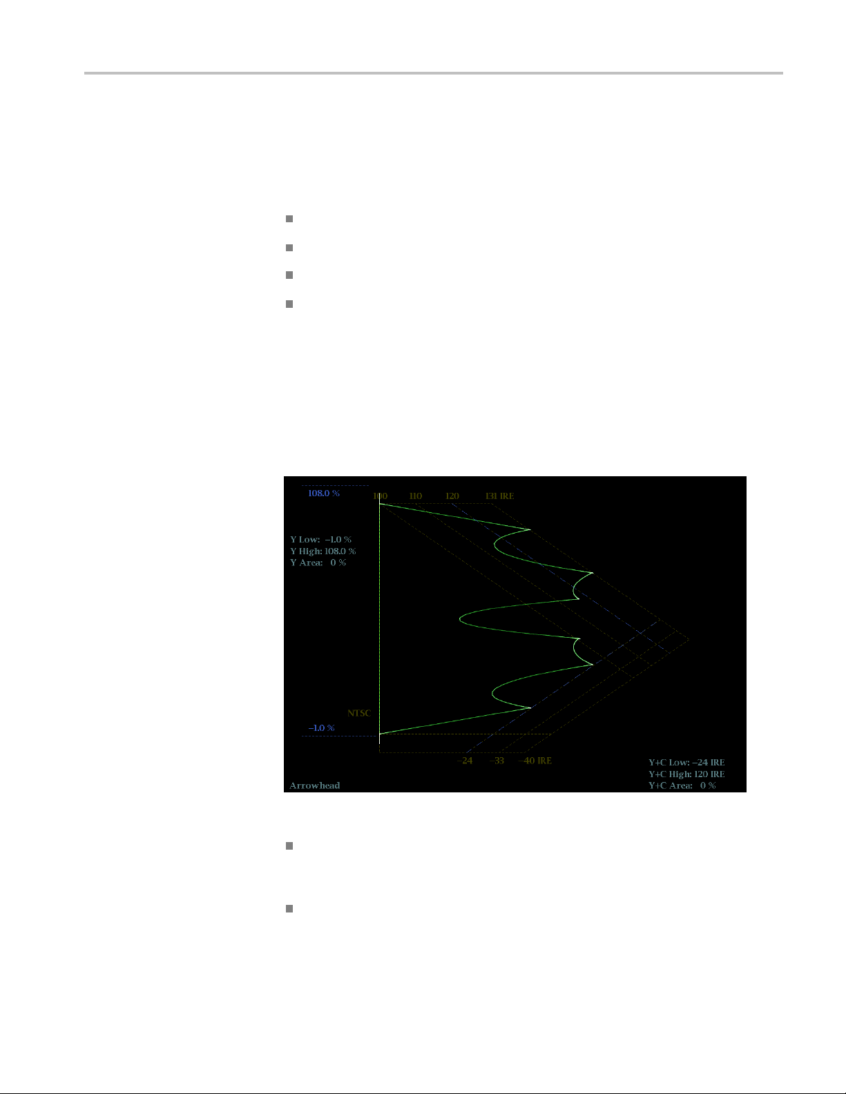
Arrowhead display
Display modes
The Arrowhead display is a Tektronix proprietary display that shows gamut
violations of the SDI input if translated into the Composite domain (NTSC and
PAL). For more information about using the gamut-checking displays:
See Diamond display (See page 64.)
See Split Diamond display (See page 79.)
See Checking gamut (See page 141.)
See the Preventing Illegal Colors application note available on the Tektronix
Web site (www.tektronix.com)
To access the
Arrowhead display
Elements of the
Arrowhead display
1. Press and hold the GAMUT button to open the Gamut pop-up menu.
2. Use the arrow keys to select Display Type > Arrowhead.
3. Press the GAMUT button to close the pop-up menu.
Figure 11: Arrowhead display
High threshold: Shows the currently specified high threshold (Arrowhead
NTSC Max or Arrowhead PAL Max) setting in the CONFIG > Gamut
Thresholds menu.
Low threshold: Shows the currently specified low threshold (Arrowhead
NTSC Min or Arrowhead PAL Min) setting in the CONFIG > Gamut
Thresholds menu.
WFM2200 Waveform Monitor & Generator User Manual 47
Page 64

Display modes
Gamut pop-up menu
(Arrowhead display)
Gamut display t
Diamond, or Split Diamond.
Threshold indicators: Indicates the threshold settings using blue dashed
lines.
Luma minimum: Shows the currently specified minimum luma threshold
(Luma Min) setting in the CONFIG > Gamut Thresholds menu.
Luma maximum: Shows the currently specified maximum luma threshold
(Luma Max) setting in the CONFIG > Gamut Thresholds menu.
YAreaand Y+C Area: Shows the specified percentage of the total image
pixels that can be outside the current luma (Y) and gamut (Y+C) limits and
not generate error reports.
Field and line numbers: Shows the currently selected video field and line
numberswhenLineSelectmodeisenabled. (Seepage122,Line select.)
Press and hold the GAMUT button to open the Gamut pop-up menu. The pop-up
menu enables you to select the from the following Tektronix proprietary gamut
displays:
Arrowhead - Displays gamut violations of the SDI input if translated into the
Composite domain (NTSC and PAL).
ype: Shows the selected Gamut display type - Arrowhead,
CONFIG menu
Diamond - Displays gamut violations of the SDI input if translated to the
RGB color space. (See page 64, Diamond display.)
Split Diamond - Like the Diamond display, displays gamut violations of the
SDI input if translated to the RGB color space. However, the Split Diamond
display offsets the two halves of the Diamond display to allow you to better
seenegativeRGBgamuterrors. (Seepage79,Split Diamond display.)
Use the CONFIG menu to set the following Arrowhead display parameters:
Use the menu selections under Gamut Thresholds to set the minimum and
maximum gamut limits for composite signals derived from the SDI signal, set
the m inimum and maximum luma levels, specify the percentage of the total
image pixels that can be outside the current gamut or luma limits and not
generate error reports, and reset the gamut and luma limits to default values.
Use the menu selections under Alarms > Video Content to enable the alarms
for the Arrowhead display.
Set the Graticules & Readouts > Gamut Readouts setting to On or Off to
turn on or off the readouts on the display.
Use the menu selections under Display Settings to set various general display
parameters which affect all applicable display modes such as waveform
intensity and graticule c olor.
48 WFM2200 Waveform Monitor & Generator User Manual
Page 65

Audio display
Display modes
The Audio display provides level meters and a phase display for monitoring audio
signals. The level meters and correlation meters are always shown. When you
choose to show the Phase plot (also known as Lissajous) or Surround Sound
displays, the left part of the Audio tile displays the level meters and the right part
the Phase or
Surround Sound display. (See Figure 12.)
To access the
Audio display
Elements of the
Audio display
1. Press and hold the AUDIO buttontoopentheAudiopop-upmenu.
2. Use the arrow keys to select the AUX display mode:
Off - Turns off the auxiliary display (Phase or Surround), which allows
the level meters to occupy the complete viewing area.
Phase display - Displays a plot of the audio phase in either 2-channel XY
or Lissajous Sound Stage modes.
Surround display - Displays a plot of the channel levels in a
surround-sound listening environment.
3. Press the AUDIO button to close the pop-up menu.
Figure 12: Audio display (Surround mode)
Level meters: Shows the audio levels. (See page 164, To check audio level.)
he response of the level meters is determined by the ballistics setting in the
T
CONFIG > Digital Audio Displays menu.
hase or Surround Display: Select between the Phase display, where the
P
phase of a selected pair of channels is plotted against an X-Y or sound-stage
plot, and the Surround display, where all the channels' levels display in
positions matching their place in a surround-sound listening environment.
(See page 165, To check audio phase.) (See page 170, Elements of the
Surround Sound display.)
WFM2200 Waveform Monitor & Generator User Manual 49
Page 66

Display modes
Audio source/s
information, such as Listening Mode when in Surround display. (See
page 163, Audio monitoring.)
Level meter labels:Identifies the signal in each meter bar. The labels vary
according to whe t her the audio sources to the level meter bars are normal
channel pairs, surround channels, or Dolby sources (the Dolby source labels
include Dolby type).
Level meter ballistics readouts: Displays the selected dynamic response
characteristic.
Axes: Shows the orientation of the two audio signals when displaying phase;
shows the orientation and amplitudes of the sound field when displaying
surround sound. (Axes are selectable for an X -Y or Soundstage plot.)
Phase correlation meters: Displays the phase correlation between the
two-channel bars under which it appears. The meter of the pair selected for
the Pha
audio phase.)
Test l
between the level bars indicate the configurable limits set up for the display.
Above the Test level, the bar displays in a yellow color. Above the Peak
level, the bar displays in a red color. Test level is also known as Reference
level or Line-up level.
se display also appears in the Phase display. (See page 165, To check
evel and Peak program level indicators: Diamond-shaped markers
etup: Displays the selected audio input and related setup
Above-bar
arning messages
w
Level meter scale and units: By default, the units are in dB relative to full
scale (dBFS) for digital inputs and dB relative to 0.775 Volts (dBu) for analog
inputs. The 0 dB mark is digital Full scale for d igital inputs and 0 dBu for
alog inputs. You may also set the 0 dB mark to either the Peak Program
an
level or the Test level.
This instrument displays warning messages above the level meter bars. The
arning messages that can appear above the bars as follows:
w
Clip. The number of consecutive samples equals or exceeds the # Samples
for Clip setting.
Over. The signal is at or above the specified Over Level for a time exceeding
the Duration for Over setting.
50 WFM2200 Waveform Monitor & Generator User Manual
Page 67

Display modes
In-bar
warning messages
This instrumen
warning m essages that can appear are s hown below in order of priority.
UNLOCKED.The
indicated input channel. Data cannot be decoded and all data and other errors
are ignored. This means that if an AES input is selected, nothing recognizable
is present on the input, or if embedded audio is selected, the VIDEO input is
unrecognizable.
AES PARITY. The incoming subframe does not have even parity as specified
by the digital audio standards. The data sample is unreliable and is ignored.
The level meters and Lissajous display treat the sample as a zero sample.
AES CRC ERROR. The CRC code in the AES channel status packet is
incorrect. Sometimes the CRC code is set to zero, indicating that the signal is
missing
MUTE. The number of consecutive a ll-zero samples equals or exceeds the
#Sampl
SILENCE. Thesignalisatorbelowthespecified Silence Level for a time
excee
DISABLED. Indicates that an audio bar is not active.
AES V BIT. Indicates that the Validity bit is set high for one or more data
samples. In the AES/EBU standard, a set Validity bit indicates that the sample
is no
t displays warning messages within the level meter bars. The
instrument is not locked to an incoming signal on the
; when this is the case, this message is not displayed.
es for Mute setting.
ding the Duration for Silence setting.
t suitable for conversion to audio.
When the Ignore Validity Bit setting is set to On in the CONFIG > Digital
io Displays submenu (the default value), the Validity bit is ignored and
Aud
the audio sample as treated as norma l audio. When the Ignore Validity Bit
setting is set to Off, then the Validity bit value is used to mute the audio when
the bit value is high.
NO AUDIO. Indicates that an AES or embedded input has the Non audio
bit set.
NOT PRESENT. Indicates that an audio channel is not present in the current
audio input.
DOLBY D. Indicates an AES or embedded input is DOLBY Digital (not plus).
DOLBY D+. Indicates an AES or embedded input is DOLBY Digital Plus.
DOLBY E . Indicates an AES or embedded input is DOLBY E.
WFM2200 Waveform Monitor & Generator User Manual 51
Page 68

Display modes
Audio pop -up menu
Press a nd hold t
pop-up menu enables you to select the audio input source and specify whether one
of the auxiliary displays (audio phase or surround-sound) appears to the right of
the level meter display. Some of the menu selections depend on the selected audio
input source and which auxiliary display is enabled.
Audio input
than Follows Video, the Audio display monitors the selected input regardless
of which video input is active.
NOTE. Use the CONFIG menu to select the mapping of audio input channels to
level bars, the meter type, and the Follows Video mapping of audio to video.
Follows Video - Sets the audio source to be from the audio source configured
for selected video input in the CONFIG > Audio Inputs/Outputs > Video to
Audio Map submenu. If you select a different video input, the audio source
then ch
AES A - Sets the audio source to be from the AES audio input.
Embedded - Sets the audio source to be from the embedded audio on the
currently selected video input. Select which eight audio channels are shown in
evel meters by configuring the Bar to Input Map settings in the CONFIG
the l
> Audio Inputs/Outputs submenus for the Embedded A, Embedded B, or
Embedded Dual Link selections.
he AUDIO button to open the Audio pop-up menu. The Audio
. When you select one of the following audio input sources other
anges to the audio source configured for that video input.
Emb. 16-Ch - Sets the audio source to be from the embedded audio on the
currently selected video input. This mode displays level meters for all 16
channels in the embedded audio, but does not display the correlation meters
nor the Phase or Surround Sound auxiliary displays.
NOTE. When the audio input source is set to Emb. 16-Ch, Emb. 1-8, or
mb. 9-16, you can use the left/right arrow keys to quickly toggle through these
E
three audio input sources.
Emb. 1-8 - Sets the audio source to be from the first eight channels in the
embedded audio on the currently selected video input. This mode displays
the correlation meters for the first eight channels and displays the Phase or
Surround Sound auxiliary displays when they are enabled.
Emb. 9-16 - Sets the audio source to be from the second eight channels in the
embedded audio on the currently selected video input. This mode displays
the correlation meters for the second eight channels and displays the Phase or
Surround Sound auxiliary displays when they are enabled.
52 WFM2200 Waveform Monitor & Generator User Manual
Page 69

Display modes
Auxiliary disp
Off - Disables the auxiliary display, which allows the level meters to occupy
thecompletev
Phase Display - Sets the auxiliary display to show a 2-channel phase display.
A phase disp
selection to choose the plot style of the phase display.
Surround Dp
sound display. Use the Dominance Indicator menu selection to turn the
dominance indicator on and off.
NOTE. The Audio Surround Sound display is courtesy of Radio-Technische
Werkstaetten GmbH & Co. KG (RTW) of Cologne, Germany.
Phase style. When Phase Display is selected as the auxiliary display, you can
select from the following display styles:
Liss Snd Stage - Displays the L and R axes rotated at 45 degrees in the
Lissajous Sound Stage style.
X-Y - Displays the L and R axes in the vertical and horizontal positions
respectively.
lay. Select from the following auxiliary displays:
iewing area in the Audio display.
lay is also called a Lissajous display. Use the Phase Style menu
. - Sets the auxiliary display to s how a multichannel surround
nance indicator. When Surround Display is selected as the auxiliary display,
Domi
use this menu selection to turn the dominance indicator on and off. When on, it
indicates the location of the dominant sound in the surround sound image using a
cross-hairs pointer.
Phase/Headphone pair. Select which audio pairs are mapped to the headphone
ck and to the phase display. When you select Custom, you can specify
ja
individual channels for the input pair using the Custom Phase A and Custom
Phase B menu selections.
Audio program. Select which program (1-8) in the embedded audio to monitor.
This setting affects the Audio display only under the following conditions:
When the bar format for the selected embedded audio source (Embedded A,
Embedded B, or Embedded Dual Link) is set to Program (Surround) in the
CONFIG > Audio Inputs/Outputs submenu.
When the selected surround sound type contains more than one program. The
type of surround sound is selected in the CONFIG > Audio Inputs/Outputs >
Program Cfg submenu.
WFM2200 Waveform Monitor & Generator User Manual 53
Page 70

Display modes
CONFIG menu
To adjust audio volume
Use the CONFIG m
Use the menu selections under Digital Audio Displays to configure various
audio display
program level, meter scaling, alarm thresholds, correlation s peed, and turning
the Lissajous AGC mode on and off.
Use the menu selections under Audio Inputs/Outputs to configure audio
input and output parameters such as selecting which channels are active on
each audio input port, selecting how eac h audio port is displayed, selecting
the audio output source, selecting which channels to de-embed from the
SDI video, configuring the “map” of active audio for each video input, and
adjustin
If Option 3G is installed, 3G Level A signals use the Embedded A or B
setting
Dual Link settings.
Use the
AES/Embedded to enable various audio alarms.
You ca
out on the instrument speakers or the headphone jack:
g the speaker and headphone volume.
s as appropriate. Dual Link and 3G Level B signals use the Embedded
menu selections under Alarms > Audio Content and Alarms >
n use any of the following methods to adjust the volume of the audio played
enu to set the following Audio display parameters:
parameters such as meter type, ballistic characteristics, peak
WARNING. To prevent the risk of hearing damage, always turn down the audio
volume before connecting headphones to the instrument. Sound levels and
impedance can vary between different headphones.
When the Audio display is s elected and no menus are active, turn the General
knob.
When a display mode other than Audio is selected, press the VOL button and
then use the General knob or the up/down arrow keys.
Select the CONFIG > Audio Inputs/Outputs > Headphone Volume
submenu item and then use the General knob or the up/down arrow keys.
At any time, press and hold the VOL button to toggle audio muting. A red
“X” appears over the speaker icon in the Status Bar when audio is muted.
NOTE. When monitoring high-amplitude audio, volume levels over 90% may
cause audio clipping.
54 WFM2200 Waveform Monitor & Generator User Manual
Page 71

Bowtie display
Display modes
The Bowtie display allows you to look at interchannel timing between Y Pb and
Y Pr. The left side of the display compares Y and Pb; the right side compares
Y and Pr. The Bowtie display requires a test signal with slightly differing
frequencies on the chroma channels than on the luma channel.
If the bowtie patterns have a s harp null, and the null is at the center of each line,
the relative amplitudes and interchannel timing are correct. Interchannel timing
errors wil
l move the position of the null:
A relative amplitude error will decrease the depth of the null
An incomplete null combined with an offset from center indicates both
amplitude and timing problems between the channels being compared
To acces
sthe
Bowtie display
Elements of the
edisplay
Bowti
1. Press and hold the MEAS button to open the Measure pop-up menu.
2. Use the arrow keys to select Display Type > Bowtie.
3. Press the MEAS button to close the pop-up menu.
Figure 13: Bowtie display
Display: Shows the display type as Bowtie.
Y-axis units: The units for the y-axis depend on the test signal and the signal
format.
X-axis units: Shows the x-axis in microseconds/divisions.
WFM2200 Waveform Monitor & Generator User Manual 55
Page 72

Display modes
Measure pop-up menu
(Bowtie display)
H and V position
the waveform, a position readout appears with a knob icon to indicate whether
the horizontal or vertical position is the focus of the General knob.
Field and line numbers: Shows the currently selected video field and line
numberswhenLineSelectmodeisenabled. (Seepage122,Line select.)
Press and ho
menu enables you to configure the d isplay type and configure display parameters
for the different display types. The following menu selections are available:
Display type. Select from the following display types:
Timing - Displays a Tektronix proprietary view that enables you to easily
compare and correct the timing between two signals. (See page 103, Timing
Measure display.)
Datalist (Option DATA only) - Displays the content of all digital signal
formats, structures, and transports (SD, HD, 3G, dual link, 4:2:2, 4:4:4, and
other
DATA only).)
Bowti
ld the MEAS button to open the Measure pop-up menu. The pop-up
s) except for composite signals. (See page 57, Datalist display (Option
e - Displays the interchannel timing between Y Pb and Y Pr.
s: When you press the POS button to adjust the position of
CONFIG menu
ANC Data (Option DATA only) - Displays all of the ANC data in a video
al. (Seepage43,ANC Data display (Option DATA only).)
sign
Parade Overlay. Select how the waveform appears by selecting Parade or
Overlay.
Center waveform. Select this option to cancel any horizontal or vertical position
justments and restore the trace to the default position.
ad
Use the CONFIG menu to set the following Bowtie display parameters:
Set the Graticules & Readouts > Waveform Readouts setting to On or Off
to turn on or off the readouts on the display.
Use the menu selections under Display Settings to set various general display
parameters which affect all applicable display modes such as waveform
intensity, graticule color, and enabling the thumbnail view.
56 WFM2200 Waveform Monitor & Generator User Manual
Page 73

Display modes
To position the
Bowtie trace
To adjust the po
1. Press the POS button.
2. Press the left or right arrow key to enable horizontal or vertical adjustments.
The knob icon appears next to the selected adjustment readout.
3. Turn the General knob or use the up/down a rrow keys to adjust the position
of the waveform.
4. Press the POS button to turn off the position adjustment mode.
Datalist display (Option DATA only)
The Datalist display allows you to see SD, HD, or 3G (Option 3G only) data
without any interpolation. The Datalist tool examines the contents of all digital
formats, structures, and transports (SD, HD, dual-link, 3 Gb/s, 4:2:2, 4:4:4, and
others). Datalist works for all signals except composite signals (analog NTSC and
analog PAL). From the display screen, you can select and isolate specific lines and
words from the video or data stream.
To access the
Datalist display
1. Press and hold the MEAS button to open the Measure pop-up menu.
2. Use the arrow keys to select Display Type > Datalist D isplay.
sition of the trace on the Bowtie display:
Elements of the
Datalist display
3. Press the MEAS button to close the pop-up menu.
Figure 14: Datalist display
WFM2200 Waveform Monitor & Generator User Manual 57
Page 74

Display modes
Datalist color coding
Use the navigat
sample items using the arrow keys and the General knob.
Line Select: Shows which line is selected; press the SEL button to switch
between Line Select and Word Select.
Word Select: Shows which word is selected; press the SEL button to switch
between Line Select and Word Select.
Samp#: Shows the sample number.
Y0, Cb, Cr, Y1: These labels change based on the signal, but they show
the line number for each component.
Different fields of the data stream are shown in different colors:
Green: Active video data.
Blue: Data in horizontal or vertical blanking intervals.
White: EAV and SAV packets; other reserved values such as the XYZ word.
Yellow: Data outside the nominal allowed values.
Red: Data with illegal values.
iontextonthebottomofthedisplayscreentoselectlineand
Finding SAV and EAV in
theactivevideostream
Measure pop-up menu
(Datalist display)
From anywhere in the video stream, press the CURSOR button once to
immediately jump to the EAV of the selected line. Press the button again to jump
to the SAV of the same line. This allows you to move quickly to the beginning of
the ANC data, which is right after the EAV.
Press and hold the MEAS button to open the Measure pop-up menu. The pop-up
menu enables you to configure the d isplay type and configure display parameters
for the different display types. The following menu selections are available:
Display type. Select from the following display types:
Timing - Displays a Tektronix proprietary view that enables you to easily
compare and correct the timing between two signals. (See page 103, Timing
Measure display.)
Datalist (Option DATA only) - Displays the content of all digital signal
formats, structures, and transports (SD, HD, 3G, dual link, 4:2:2, 4:4:4, and
others) except for composite signals.
Bowtie - Displays the interchannel timingbetweenYPbandYPr. (See
page 55, Bowtie display.)
ANC Data (Option DATA only) - Displays all of the ANC data in a video
signal. (See page 43, ANC Data display (Option DATA only).)
58 WFM2200 Waveform Monitor & Generator User Manual
Page 75

Display modes
Trace type. Sel
Video - This mode shows the data similar to the video YPbPr display in
Waveform mode
offset vertically to separate them, but are aligned temporally. You can select
to turn on or off individual component traces of the display.
Data - For an SD signal, this mode shows the data in the same sequence as
it occurs in the serial domain. You see a sample of Y, then of Cb, then of Y'
(Y prime), and then of Cr. Then the sequence repeats. The Y sample is the
co-sited sample and the Y' sample is the isolated luma sample.
For an HD signal, this mode splits the serial input into a Y channel and a
multiplexed Cb/Cr channel. The intent is to show the data in the same block
structure as it occurs in the serial domain, even though it is displayed as 8
or 10-bi
Trace Y, Trace Cb, and Trace Cr. When the Trace Type is set to Video, use these
selections to turn on or off the individual component traces of the display.
Format. Set the data format to Hexadecimal, Decimal, or Binary. The default
ormat is Hexadecimal.
data f
ect from the following trace types (Video is the default setting):
, but without interpolation. The Y, Cb, and Cr traces are
tvalues.
CONFIG menu
Use the CONFIG menu to set the following Datalist display parameters:
Use the menu selections under Display Settings to set various general display
parameters which affect all applicable display modes such as readout intensity
and graticule color.
Use the menu selections under Aux Data Settings to set various data
parameters.
Use the menu selections under Alarms to enable various alarms that will
highlight data as errors.
WFM2200 Waveform Monitor & Generator User Manual 59
Page 76

Display modes
Diagnostics Monitor display
The Diagnostics Monitor display shows the status of various instrument
diagnostics. Use the up and down arrow keys to navigate through the different
pages of the display.
To access the
Diagnostics Monitor
display
Elements of the
Diagnostics Monitor
display
1. Press and hold the GEN button to open the Generator pop-up menu.
2. Use the arrow keys to select Display Type > Diag Monitor.
3. Press the G
Elements on all pages. There are four pages to the Diagnostics Monitor display.
The following information appears on all pages of the display:
Session Start: Shows the date and time of the instrument when the Diagnostic
Monitor session started. This start time applies to a ll of the pages in the
Diagnostics Monitor display.
Run Time: Shows the amount of time that has elapsed since the Diagnostic
Monitor session was started. This run time applies to all of the pages in the
Diagnostics Monitor display.
ntsonPage1. The following instrument diagnostic information appears on
Eleme
page 1 of the display: (See Figure 15.)
Fan S
and low speed measurements for each fan since the instrument was turned on.
peratures: Shows the last, low, high, and average temperatures for
Tem
various internal components.
EN button to close the pop-up menu.
peed (rpm): Shows the current speed of both internal fans and the high
Elements on Pages 2 and 3. The following instrument diagnostic information
appears on pages 2 and 3 of the display: (See Figure 16.) (See Figure 17.)
Power Supply Voltages: Shows the last, low, high, and average power supply
voltages for various internal components.
Elements on Page 4. The following instrument diagnostic information appears on
page 4 of the display: (See Figure 18.)
External Power & Battery Information: Shows the status of various
parameters related to the operation of the battery pack. If a battery pack is not
installed in the instrument, the Status readout shows “Not Present” and the
diagnostic parameters will list “N/A” as the status.
60 WFM2200 Waveform Monitor & Generator User Manual
Page 77
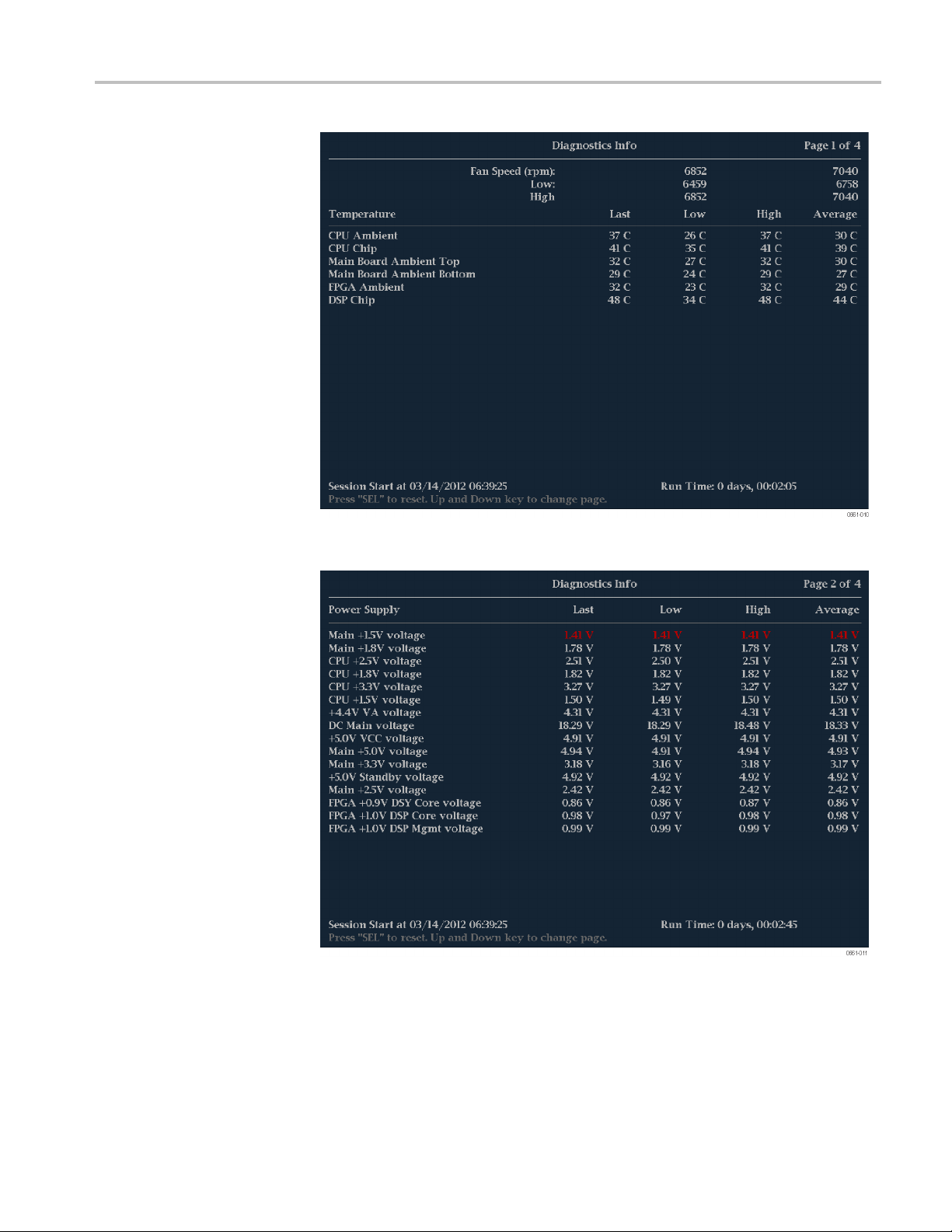
Display modes
Figure 1
Figure 16: Diagnostics Monitor display (page 2)
5: Diagnostics Monitor display (page 1)
WFM2200 Waveform Monitor & Generator User Manual 61
Page 78
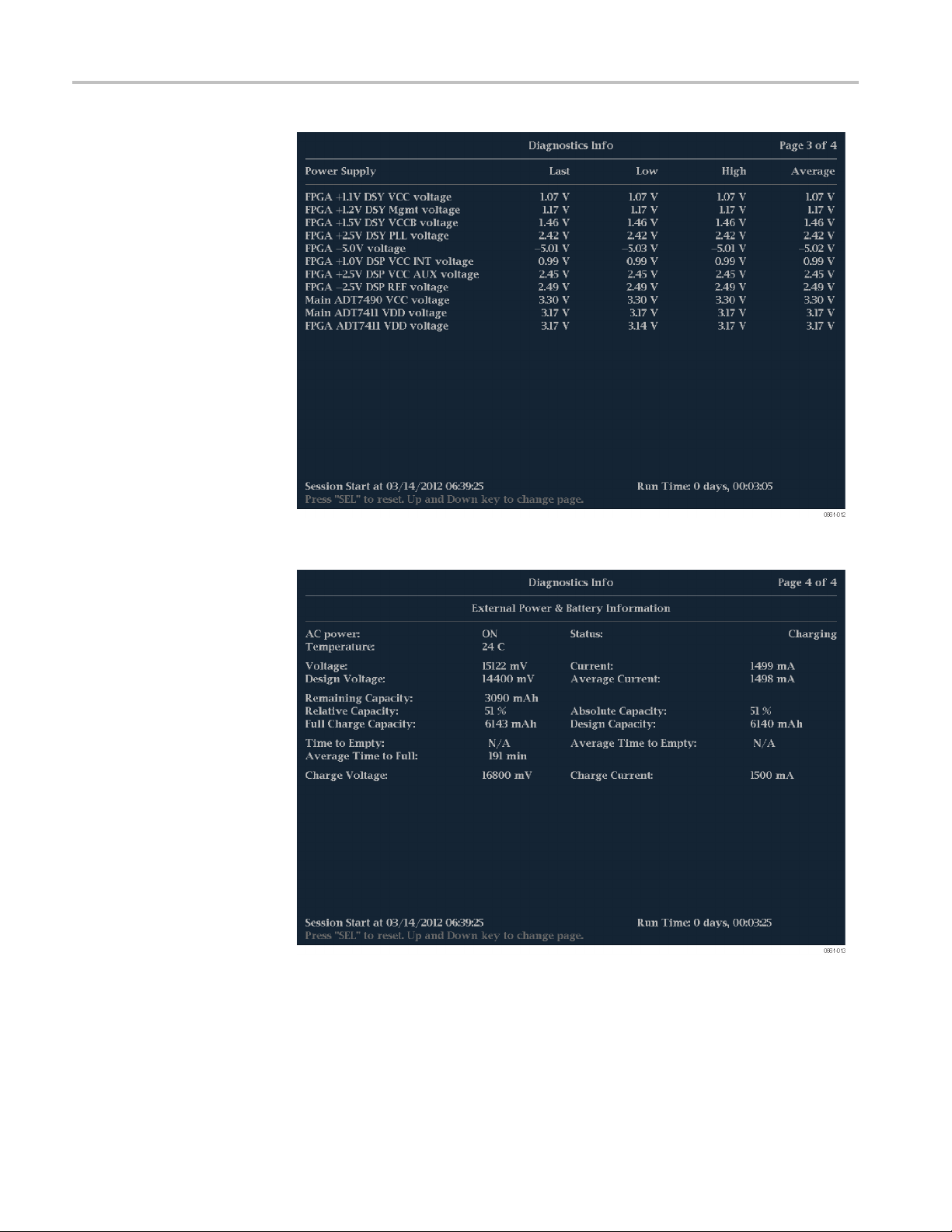
Display modes
Figure 17
Figure 18: Diagnostics Monitor display (page 4)
: Diagnostics Monitor display (page 3)
62 WFM2200 Waveform Monitor & Generator User Manual
Page 79

Display modes
Generator pop-up menu
(Generator Status display)
CONFIG men
Press and hold t
menu selections are a vailable:
Display Type. Select from the following display types:
Generator Status – Displays the status of both video and audio signals being
generated b
Diagnostics Monitor – Displays the status of various instrument diagnostics.
The diagnostic information that is viewed from the Diagnostics Monitor displays
u
is different than the diagnostics that are run when the instrument is powered on.
You can use the CONFIG menu to view and configure the following Diagnostics
Log param
Use the Alarms > System and Diagnostics setting to enable an alarm for
ahardwa
Use the menu selection under Utilities to run diagnostics, to set how the
diagno
configure custom diagnostics.
he GEN button to open the Generator pop-up menu. The following
y the instrument. (See page 68, Generator Status display.)
eters:
re fault.
stics log responds when full, to view the diagnostics log, and to
WFM2200 Waveform Monitor & Generator User Manual 63
Page 80

Display modes
Diamond display
The Diamond display is a Tektronix proprietary display that shows gamut
violations of the SDI input if translated to the RGB color space. For more
information a bout using the gamut-checking displays:
See Arrowhead display (See page 47.)
See Split Diamond display (See page 79.)
See Checking gamut (See page 141.)
See the Preventing Illegal Colors application note available on the Tektronix
Web site (www.tektronix.com)
To access the
Diamond display
Elements of the
Diamond display
1. Press and hold the GAMUT button to open the Gamut pop-up menu.
2. Use the arrow keys to select Display Type > Diamond.
3. Press the GAMUT button to close the pop-up menu.
Figure 1 9: Diamond display
High threshold: Shows the currently specified Diamond High threshold
setting in the CONFIG > Gamut Thresholds menu.
Low threshold: Shows the currently specified Diamond Low threshold
setting in the CONFIG > Gamut Thresholds menu.
Gamut display type: Shows the selected Gamut display type - Arrowhead,
Diamond, or Split Diamond.
64 WFM2200 Waveform Monitor & Generator User Manual
Page 81

Display modes
Gamut pop-up menu
(Diamond d
isplay)
Threshold i ndi
lines.
YArea: Shows t
outside the current gamut limits and not generate error reports.
Field and li
numbers when Line Select mode is enabled. (See page 122, Line select.)
Press and hold the GAMUT button to open the Gamut pop-up menu. The pop-up
menu enabl
displays:
Arrowhea
Composite domain (NTSC and PAL). (See page 47, Arrowhead display.)
Diamond
RGB color space.
Split D
SDI input if translated to the RGB color space. However, the Split Diamond
display o ffsets the two halves of the Diamond display to allow you to better
see negative RGB gamut errors. (See page 79, Split Diamond display.)
es you to select the from the following Tektronix proprietary gamut
iamond - Like the Diamond display, displays gamut violations of the
cators: Indicates the threshold settings using blue dashed
he specified percentage of the total image pixels that can be
ne numbers: Shows the currently selected video field and line
d - Displays gamut violations of the SDI input if translated into the
- Displays gamut violations of the SDI input if translated to the
CONFIG menu
Use the CONFIG menu to set the following Diamond display parameters:
he menu selections under Gamut Thresholds to set the minimum and
Use t
maximum gamut limits for composite signals derived from the SDI signal, set
the minimum and maximum luma levels, specify the percentage of the total
image pixels that can be outside the current gamut or luma limits and not
generate error reports, and reset t he gamut and luma limits to default values.
Use the menu selections under Alarms > Video Content to enable the alarms
for the Diamond display.
Set the Graticules & Readouts > Gamut Readouts setting to On or Off to
turn on or off the readouts on the display.
Use the menu selections under Display Settings to set various general display
parameters which affect all applicable display modes such as waveform
intensity and graticule color.
WFM2200 Waveform Monitor & Generator User Manual 65
Page 82

Display modes
External Refe
To access the
External Reference
Waveform display
Elements of the
External Reference
Waveform display
rence Waveform display
The External Reference Waveform display allows you to check the integrity of the
reference signal on the EXT REF connector, including its shape and amplitude.
This display
1. Press and hold the WFM button to open the Waveform pop-up menu.
2. Use the arrow keys to select Display Type > Ref Waveform.
3. Press the WFM button to close the pop-up menu.
is independent of the input video signal. (See Figure 20.)
Figure 20: External Reference Waveform display (tri-level sync signal)
Display: Shows the display type as External Reference.
Y-axis units: Shows the y-axis units in millivolts per division.
axis units: Shows the x-axis in milliseconds or microseconds per division
X-
depending on the sweep setting.
Gain: When you press the GAIN or VAR buttons to change the gain
V
setting, a V Gain readout appears.
and V positions: When you press the POS button to adjust the position of
H
the waveform, a position readout appears with a knob icon to indicate whether
the horizontal or vertical position is the focus of the General knob.
66 WFM2200 Waveform Monitor & Generator User Manual
Page 83

Display modes
Waveform pop-up menu
(External Reference
Waveform display)
CONFIG menu
Press and hold t
menu enables you to configure the display type and to center the waveform. The
following menu selections are available:
Display type. Select from the following display types:
Wavef orm - Displays a voltage versus time plot of the selected SDI input
signal(SDIAorSDIB).(Seepage111,Waveform display.)
LTC Waveform - Displays a voltage versus time plot of the LTC input signal
(LTC IN). (See page 74, LTC Waveform display.)
Ref Waveform - Displays a voltage versus time plot of the external reference
input signal (REF IN).
Center w
adjustments and restore the trace to the default position. This puts the baseline at
the zero graticule.
Use the
parameters:
aveform. Select this option to cancel any horizontal or vertical position
CONFIG menu to set the following External Reference Waveform display
Set th
expected format from the list.
he WFM button to open the Waveform pop-up menu. The pop-up
e External Reference > Lock to Format setting to Auto or select the
To position the
External Reference
Waveform trace
he Alarms > Reference Input settings as desired.
Set t
Set the Graticules & Readouts > SDI Waveform Graticules setting to
mal or Percent to set t he measurement units for the vertical axis.
Nor
Set the Graticules & Readouts > Waveform Readouts setting to On or Off
turn on or off the readouts on the display.
to
Use the menu selections under Display Settings to set various general display
arameters which affect all applicable display modes such as waveform
p
intensity and graticule color.
o adjust the position of the trace on the External Reference Waveform display:
T
1. Press the POS button.
2. Press the left or right arrow key to enable horizontal or vertical adjustments.
The knob icon appears next to the selected adjustment readout.
3. Turn the General knob or use the up/down a rrow keys to adjust the position
of the waveform.
4. Press the POS button to turn off the position adjustment mode.
WFM2200 Waveform Monitor & Generator User Manual 67
Page 84
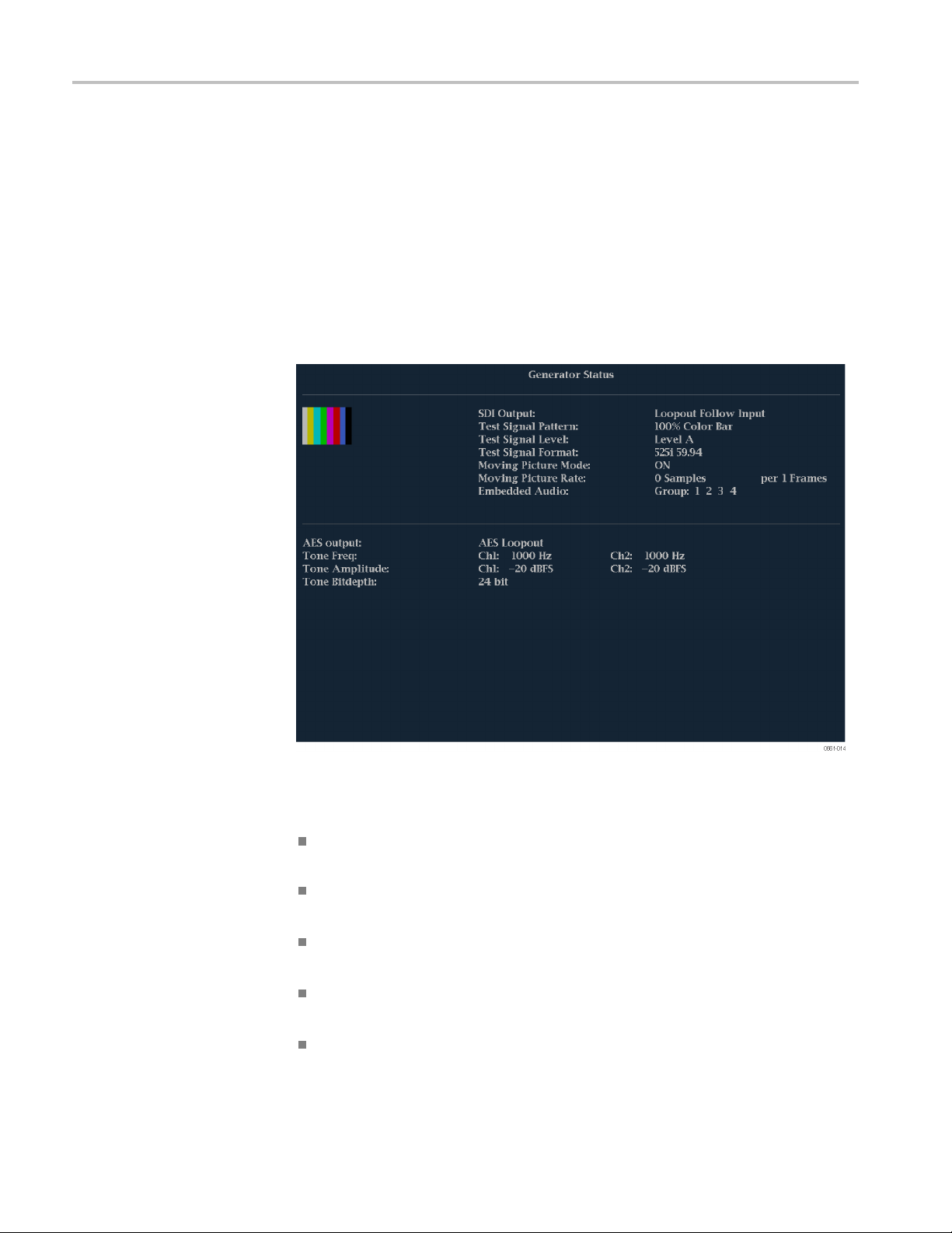
Display modes
Generator Sta
tus display
To access the
Genera
tor Status display
Elements of the
Generator Status display
The Generator Status display shows the status of both video and a udio signals
being generated by the instrument.
1. Press and hold the GEN button to open the Generator pop-up menu.
2. Use the arrow keys to select Display Type > Generator Status.
3. Press the GEN button to close the pop-up menu.
Figure 21: Generator Status display
The following video signal generator status elements appear on the display:
Thumbnail picture: Shows a thumbnail display of the picture generated by
the output signal of the video generator.
DI Output: Shows whether the SDI output is set to be a test signal or a
S
loopout of the selected SDI video input.
Test Signal Pattern: Shows which test signal will be output when the SDI
Output setting is Test Signal.
Test Signal Level: Shows the signal level (A or B) that will be output when
the SDI Output setting is Test Signal.
Test Signal Format: Shows the signal format that will be output when the
SDI Output setting is Test Signal.
68 WFM2200 Waveform Monitor & Generator User Manual
Page 85

Display modes
Moving Picture
on or off.
Moving Picture Rate: Shows the frame and sample rate settings for the
Moving Picture mode.
Embedded Audio: Shows which embedded audio groups are turned on in the
video signal output when the SDI Output setting is Test Signal.
The following audio signal generator status elements appear on the display:
AES Output: Shows w hether the AES output is turned off, is set to be a test
tone signal, or is set to be a loopout of the AES input signal or the embedded
audio from the selected video input.
Tone Frequency: Shows the test tone audio frequencies for channel 1 and
channel 2 when the AES Output setting is Test Tone.
Tone Amplitude: Shows the test tone audio amplitudes for channel 1 and
channel 2 when the AES Output setting is Test Tone.
Tone Bitdepth: Shows the test tone audio bitdepth (20 bit or 24 bit) when
the AES Output setting is Test Tone.
NOTE. The above tone frequency, amplitude, and bitdepth settings are used in
both the AES audio output and in the embedded audio of the SDI video output.
The same audio channel pair is duplicated to all pairs of embedded audio.
Mode: Shows whether the Moving Picture mode is turned
Generator pop-up menu
(Generator Status display)
Press and hold the GEN button to open the Generator pop-up menu. The pop-up
menu provides a shortcut to the same settings controlled in the CONFIG > Outputs
menu. The following menu selections are available:
Display Type. Select from the following display types:
Generator Status – Displays the status of both video and audio signals being
generated by the instrument.
Diagnostics Monitor – Displays the status of various instrument diagnostics.
(See page 60, Diagnostics Monitor display.)
SDI Output. Sets the SDI video output to be a test signal or a loopout of the
selected SDI video input.
Signal Pattern. When the SDI Output setting is Test Signal, selects the signal to
be output (100% C olor Bar, 75% Color Bar,
Signal Level. When the SDI Output setting is Test Signal, selects the level of
the output signal (Level A or Level B).
Signal Format. When the SDI Output setting is Test Signal, selects the format of
the output signal.
or Pathological Signal).
WFM2200 Waveform Monitor & Generator User Manual 69
Page 86

Display modes
Moving Picture
Picture mode on and off.
Per Frames. When the SDI Output setting is Test Signal and the Moving Picture
mode is on, sets the frame rate for the moving picture.
Moving Samp
Picture mode is on, sets the sample rate for the moving picture.
Embedded Audio. When the SDI Output setting is Test Signal, selects which
embedded audio groups are enabled in the video output signal (groups 1 through
4).
AES Output. Sets the AES audio output to be off, a test tone signal, a loopout of
the AES audio input, or a loopout of the embedded audio from the selected video
input signal.
Audio Frequency. When the AES Output setting is Test Signal, sets the frequency
test tone output for channels 1 and 2.
of the
Audio Amplitude. When the AES Output setting is Test Signal, sets the amplitude
of the test tone output for channels 1 and 2.
. When the SDI Output setting is Test Signal, turns the Moving
les. When the SDI Output setting is Test Signal and the Moving
CONFIG menu
Audio Bitdepth. When the AES Output setting is Test Signal, s ets the bitdepth of
test tone output to 20 bit or 24 bit.
the
The settings controlled in the Generator Status pop-up menu are duplicated in the
CONFIG > Outputs menu. Changes made in the Generator Status pop-up menu
mediately appear in the CONFIG > Outputs menu selections.
im
70 WFM2200 Waveform Monitor & Generator User Manual
Page 87
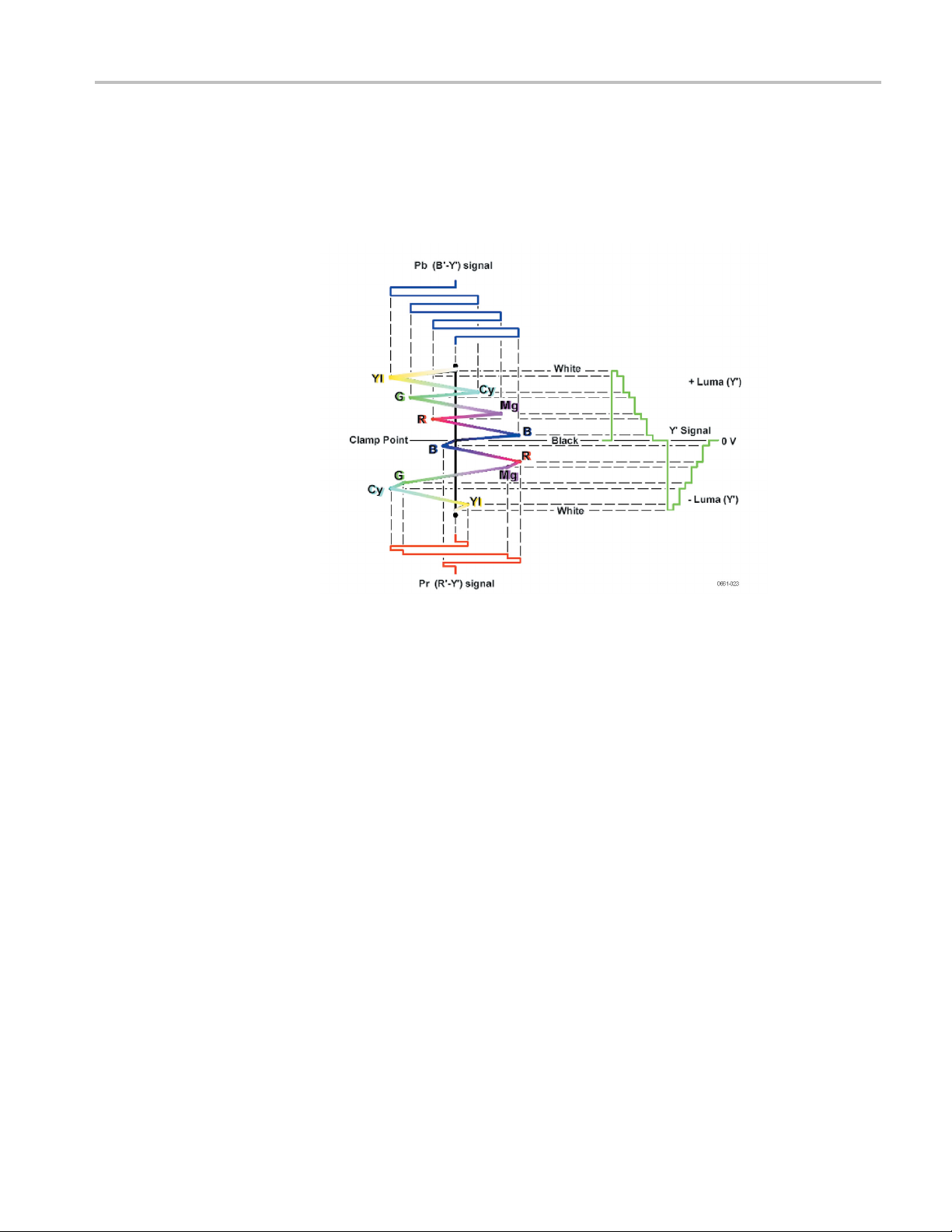
Lightning display
Display modes
The Lightning display is a Tektronix proprietary display that plots the Pr and Pb
signals against luminance. As shown below, Y versus Pb is plotted in the top half
of the display and Y versus Pr is plotted in the bottom half.
To access the
Lightning display
Figure 22: Construction of the Lightning display
This display is u seful for checking chroma and luma gain, and for checking
chroma to luma delay using the timing marks that show errors in the green to
magenta transition on a color bar signal.
You can set the color bar targets to 75% or 100% and center the trace within
the tile.
The related Vector display plots the Pr signal on the vertical axis and the Pb signal
on the horizontal axis, which is useful for looking at hue and amplitude of the
colors, but does not show luminance information. (See page 107, Vector display.)
1. Press and hold the VECTOR button to open the Vector pop-up menu.
2. Use the arrow keys to select Display Type > Lightning.
ress the VECTOR button to close the pop-up menu.
3.P
WFM2200 Waveform Monitor & Generator User Manual 71
Page 88

Display modes
Elements of the
Lightning display
Figure 23: Lightning display
The following elements appear on the display:
VGain: Shows the current vertical gain setting when the gain is other than
1x. Press the GAIN button to toggle the vertical gain between 1x and the most
ly selected vertical gain value. Press and hold the GAIN button to select
recent
fixed gain settings (1x, 2x, 5x, or 10x) or to enable VAR Gain mode. If you
enable VAR Gain mode in the Gain pop-up menu or by pressing the VAR
button, you can adjust the vertical gain using the General knob.
HGain: Shows the current horizontal gain setting when the gain is other than
1x. Press the MAG button to toggle the horizontal gain between 1x and the
most recently selected horizontal gain value. Press and hold the MAG button
to select fixed gain settings (2x, 5x, or 10x) or to enable VAR H Gain mode.
ou enable Variable H Gain mode, you can adjust the horizontal gain using
If y
the General knob.
splay Type: The selected display, either Lightning or Vector.
Di
Bar Target Setting: The bar target setting, either 75% or 100%.
H and V positions: When you press the POS button to adjust the position of
the waveform, a position readout appears with a knob icon to indicate whether
he horizontal or vertical position is the focus of the General knob.
t
Field and line numbers: Shows the currently selected video field and line
numberswhenLineSelectmodeisenabled. (Seepage122,Line select.)
72 WFM2200 Waveform Monitor & Generator User Manual
Page 89

Display modes
Vector pop-up menu
(Lightning display)
CONFIG menu
Press and hold t
menu enables you to specify the display type and display mode, to set the bar
targets, and to center the waveform in the display. The following menu selections
are available:
Display Type. Select from the following display types:
Vector – The Vector display shows a plot of the Pr signal on the vertical axis
and the Pb signal on the horizontal axis. This display is useful for looking at
hue and amp
(See page 107, Vector display.)
Lightnin
color signals as in the Vector mode, but they are plotted against luminance.
Bar Targets. To select which scaling (75% or 100%) will be used in the current
tile for either the Vector or Lighting display.
Center
adjustments and restore the trace to the default position at the center of the tile.
Use the CONFIG menu to set the following Lightning display parameters:
Waveform. Select this option to cancel any horizontal or vertical position
he VECTOR button to open the Vector pop-up menu. The pop-up
litude of the colors, but does not show luminance information.
g – This Tektronix proprietary display shows the same Pr and Pb
To position the
Lightning trace
Set the SDI Input > HD Colorimetry setting to Auto, ITU 709-2,or
SMPTE 240M to set the expected colorimetry in HD signals.
Set the Graticules & Readouts > Vector Readouts setting to On or Off to
turn on or off the readouts on the display.
Use the menu selections under Display Settings to set various general display
parameters which affect all applicable display modes such as waveform
tensity and graticule color.
in
To adjust the position of the trace on the Lightning display:
1. Press the POS button.
2. Press the left or right arrow key to enable horizontal or vertical adjustments.
The knob icon appears next to the selected adjustment readout.
3. Turn the General knob or use the up/down a rrow keys to adjust the position
of the waveform.
4. Press the POS button to turn off the position adjustment mode.
WFM2200 Waveform Monitor & Generator User Manual 73
Page 90
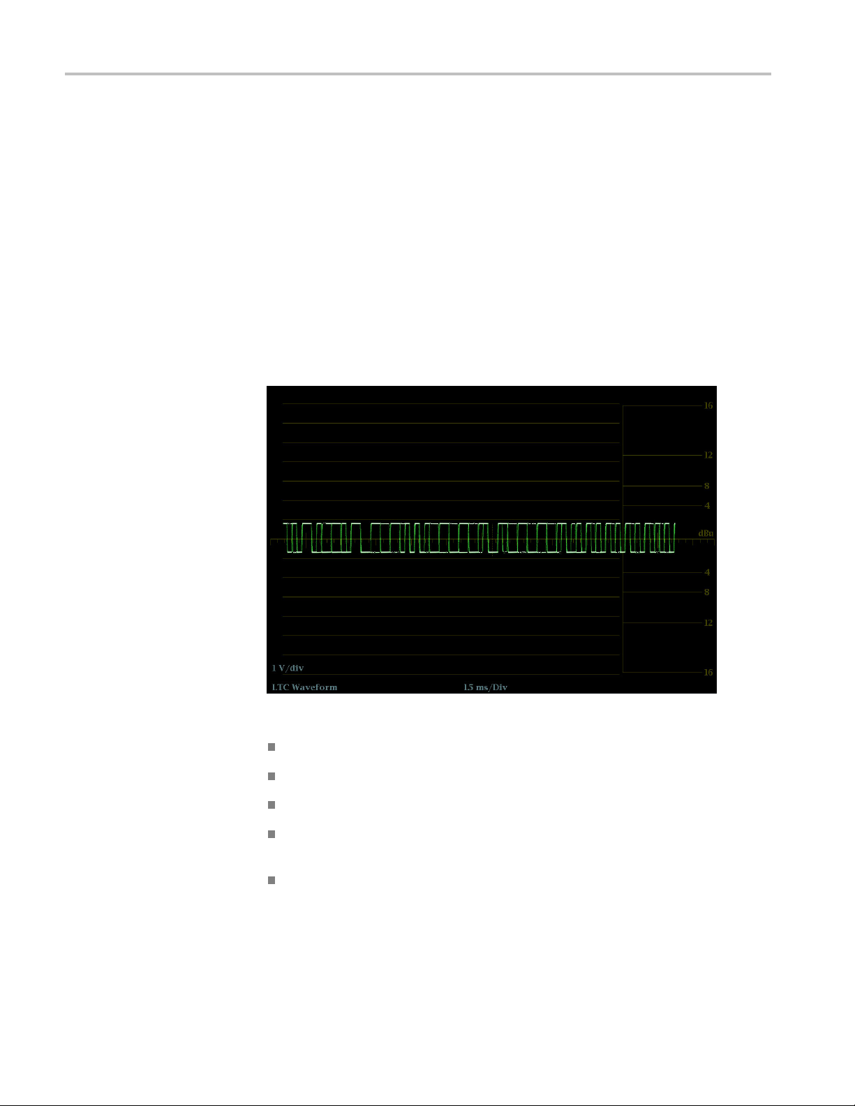
Display modes
LTC Waveform d
To access the
LTC Waveform display
Elements of the
LTC Waveform display
isplay
The LTC (Longitudinal Time Code) Waveform display is a frame rate display
of the signal on the LTC IN connector to allow observation of amplitude,
synchroniza
and corresponds to a video frame. The LTC phase should remaining consistent
relative to the frames that it is supposed to count.
1. Press and h
2. Use the arrow keys to select Display Type > LTC Waveform.
3. Press the WFM button to close the pop-up menu.
tion, and phase. The displayed waveform is basically a 2-field sweep
old the WFM button to open the Waveform pop-up menu.
Figure 24: LTC Waveform display
Display: Shows the display type as LTC Waveform.
Y-axis units: Shows the y-axis units in volts/divisions.
X-axis units: Shows the x-axis in milliseconds/divisions.
Gain: When you press the GAIN or VAR buttons to change the gain
V
setting, a V Gain readout appears.
and V positions: When you press the POS button to adjust the position of
H
the waveform, a position readout appears with a knob icon to indicate whether
the horizontal or vertical position is the focus of the General knob.
74 WFM2200 Waveform Monitor & Generator User Manual
Page 91

Display modes
Waveform pop-up menu
(LTC Waveform display)
CONFIG menu
Press and hold t
menu enables you to configure the display type and to center the waveform. The
following menu selections are available:
Display type. Select from the following display types:
Wavef orm - Displays a voltage versus time plot of the selected SDI input
signal(SDIAorSDIB).(Seepage111,Waveform display.)
LTC Waveform - Displays a voltage versus time plot of the LTC input signal
(LTC IN).
Ref Waveform - Displays a voltage versus time plot of the external reference
input signal (REF IN). (See page 66, External Reference Waveform display.)
Center w
adjustments and restore the trace to the default position.
Use the CONFIG menu to set the following LTC Waveform display parameters:
aveform. Select this option to cancel any horizontal or vertical position
Set the Graticules & Readouts > Waveform Readouts setting to On or Off
to turn on or off the readouts on the Waveform display.
Use the menu selections under Display Settings to set various general display
parameters which affect all applicable display modes such as waveform
nsity, graticule color, and enabling the thumbnail view.
inte
he WFM button to open the Waveform pop-up menu. The pop-up
position the
To
LTC Waveform trace
Set the Alarms > Timecode settings as desired to enable timecode alarms.
Set the AuxDataSetting>TimecodeSourceselection as appropriate for the
type of timecode signal you are using.
To adjust the position of the trace on the LTC Waveform display:
1. Press the POS button.
2. Press the left or right arrow key to enable horizontal or vertical adjustments.
The knob icon appears next to the selected adjustment readout.
3. Turn the General knob or use the up/down a rrow keys to adjust the position
of the waveform.
4. Press the POS button to turn off the position adjustment mode.
WFM2200 Waveform Monitor & Generator User Manual 75
Page 92

Display modes
Picture display
The Picture display shows the picture generated by the selected video signal. You
can choose to display the picture with or without a picture frame, VChip ratings,
closed captioning (CC), teletext, and safe area graticules.
For more information, see Closed captioning (CC), teletext, AFD, and safe area
compliance. (Seepage172.)
To access the
Picture display
Elements of the
Picture display
Press the PICT button to display a picture of the selected video input signal.
Figure 25: Picture display of color bars signal with Safe Area and Picture Center
graticules enabled
Picture – In full-screen mode, there is no cropping. Pictures are decimated
horizontally and vertically to obtain the correct aspect ratio. This decimation
may introduce minor artifacts in some images and may be more evident on
weep signal.
as
In Quad Tile display mode, the picture is decimated to fit in the space
ailable. For example, for 525-line signals, 12 lines are cropped (6 at the top
av
and 6 at the bottom) to make the image fit.
Chip rating: Displays detected VChip ratings from any of these systems:
V
MPAA (US), TV (US), Canadian English, and Canadian French. VChip
information is labeled CA (Content Advisory).
76 WFM2200 Waveform Monitor & Generator User Manual
Page 93

Display modes
Safe Action are
Action and Safe Title area graticules are displayed to show the safe areas of
the picture to aid in monitoring for incorrect placement of graphics, logos, and
other branding elements to ensure that they do not obscure text of essential
action. The graticule areas indicate the maximum image area within which
all significant action or titles should be contained.
The graticule sizes are defined by the selected standard (SMPTE, BBC, or
ARIB B-4) and the selected aspect ratio (Auto, 4x3, 14x9, 16x9, or Custom).
Custom set
display up to four safe area graticules (two Safe Action and two Safe Title) at
a time. You can specify up to two custom safe area graticules.
Picture Center graticule – When enabled, shows the center of the picture
image.
AFD graticules – When enabled, AFD (Active Format Descriptor) graticules
are displayed if AFD is included in the signal. When AFD is not included in
the signal, the message “AFD: Not Detected” is displayed.
Line Select cursor –WhenthePictureLineSelectCursorisenabledinthe
CONFIG > Graticules & Readouts menu, the cursor highlights the selected
line in the picture when Line Select mode is enabled.
Closed Caption Text and Teletext content: Displays closed captioning or
Teletext, configurable to decode to the following Closed Caption and Teletext
standards. When no content is detected, the message “No CC/Teletext” is
played.
dis
a and Safe Title area graticules – When enabled, Safe
tings will override the aspect ratio of the monitored input. You can
Picture p op-up menu
For SD: CEA-608-line-21, TeletextB VBI (625), CEA-608 (ANC),
A-608 (708), CEA-708, TeletextB VBI, TeletextB OP47 SDP (ANC),
CE
and TeletextB OP47 Multi (ANC)
or HD and 3G: CEA-608 (ANC), CEA-608 (708), CEA-708, TeletextB
F
VBI, TeletextB OP47 SDP (ANC), and TeletextB OP47 Multi (ANC)
ield and line numbers: Shows the currently selected video field and line
F
numbers when Line Select mode is enabled. (See page 122, Line select.)
Press and hold the PICT button to open the Picture pop-up menu. The pop-up
menu enables you to display Safe Area, AFD, and Picture Center graticules and to
display Closed Caption and Teletext content.
Picture Frame: Turns the Picture Frame display On or Off. When turned on,
only the active video portion of the signal is displayed. When turned off, the
elements of the signal that are outside of the active video signal such as user
data, embedded audio, and the vertical interval are visible.
CC/Teletext Format: Select the format of the closed caption content in the
video signal. You can select from Off, A uto, CEA608, CEA708, and WST.
WFM2200 Waveform Monitor & Generator User Manual 77
Page 94

Display modes
CONFIG menu
CEA608 CC Servi
channel that you want to monitor. You can select from CC Channel 1 through
4 and Txt Channel 1 through 4.
CEA708 CC Services: If you are monitoring CEA 708 content, select the
service that you want to monitor. You can select from Service 1 through 6.
TtxtB Page: If you are monitoring Teletext B content, select the page number
that you want to monitor.
Safe Area Action 1/2, Safe Area Title 1/2: Set the aspect ratio of the selected
Safe Area Action or Safe Area Title graticule. Select from Off, Auto, 4x3,
14x9, 16x9, Custom_1, and Custom_2. Use the Custom Safe Action/Title
settings in the CONFIG > Graticules & Readouts menu to define the custom
safe areas.
AFD Graticules: If AFD is included in the signal, use this setting to turn
AFD graticules on or off.
Picture Center Grat: Turns the graticule showing the center of the picture
on or off.
Use the CONFG menu to set the following Picture display parameters:
Use the Graticlues & Readouts > Safe Area Graticule Standard selections
to select the standard used for Safe Action and Safe Title area graticules.
ces: If you are monitoring CEA 608 content, select the
Use the Graticlues & Readouts > Custom Safe Action/Title selections to
set the dimensions and offset for the custom Safe Action and Safe Title area
graticules.
Use the Graticlues & Readouts > Picture
on or off the highlight of the selected line in the picture when Line Select
mode is enabled.
Use the Graticules & Readouts > Picture Readouts setting to turn on or off
the readouts and graticules on the Picture display.
Set the Aux Data Settings > CEA 608 Settings selections as appropriate if
you are monitoring video with CEA 608 closed caption content.
Set the Aux Data Settings > CEA 708 Settings selections as appropriate if
you are monitoring video with CEA 708 closed caption content.
Set the Aux Data Settings > Teletext B Settings selections as appropriate if
you are monitoring video with Teletext B content.
Use the menu selections under Display Settings to set various general display
parameters which affect all applicable display modes such as waveform
intensity, graticule color, and enabling the thumbnail view of the Picture
display in the Waveform, Vector, or Gamut displays. (See page 32, DISPLAY
SELECT button.)
Line Select Cursor setting to turn
78 WFM2200 Waveform Monitor & Generator User Manual
Page 95

Display modes
Split Diamond
To access the
Split Diamond display
Elements of the
Split Diamond display
display
Like the Diamond display, the Split Diamond display is a Tektronix proprietary
display that shows gamut violations of the SDI input if translated to the RGB
color space.
See Arrowhead display (See page 47.)
See Diamond display (See page 64.)
See Checking gamut (See page 141.)
See the Preventing Illegal Colors application note available on the Tektronix
Web site (www.tektronix.com)
1. Press and hold the GAMUT button to open the Gamut pop-up menu.
2. Use the arrow keys to select Display Type > Split Diamond.
3. Press the GAMUT button to close the pop-up
For more information about using the gamut-checking displays:
menu.
Figure 26: Split Diamond display
High threshold: Shows the currently specified Diamond High threshold
setting in the CONFIG > Gamut Thresholds menu.
Low threshold: Shows the currently spe cified Diamond Low threshold
setting in the CONFIG > Gamut Thresholds menu.
Gamut display type: Shows the selected Gamut display type - Arrowhead,
Diamond, or Split Diamond.
WFM2200 Waveform Monitor & Generator User Manual 79
Page 96

Display modes
Gamut pop-up menu
(Split Dia
mond display)
Threshold indi
lines.
YArea: Shows t
outside the current gamut limits and not generate error reports.
Field and li
numberswhenLineSelectmodeisenabled. (Seepage122,Line select.)
Press and hold the GAMUT button to open the Gamut pop-up menu. The pop-up
menu enabl
displays:
Arrowhea
Composite domain (NTSC and PAL). (See page 47, Arrowhead display.)
Diamond
color space. (See page 64, Diamond display.)
Split D
SDI input if translated to the RGB color space. However, the Split Diamond
display offsets the two halves of the Diamond display to allow you to better
see negative RGB gamut errors.
es you to select the from the following Tektronix proprietary gamut
iamond - Like the Diamond display, displays gamut violations of the
cators: Indicates the threshold settings using blue dashed
he specified percentage of the total image pixels that can be
ne numbers: Shows the currently selected video field and line
d - Displays gamut violations of the SDI input if translated into the
- Displays gamut violations of the SDI input if translated to RGB
CONFIG menu
Use the CONFIG menu to set the following Split Diamond display parameters:
he menu selections under Gamut Thresholds to set the minimum and
Use t
maximum gamut limits for composite signals derived from the SDI signal, set
the m inimum and maximum luma levels, specify the percentage of the total
image pixels that can be outside the current gamut or luma limits and not
generate error reports, and reset the gamut and luma limits to default values.
Use the menu selections under Alarms > Video Content to enable the alarms
for the Split Diamond display.
Set the Graticules & Readouts > Gamut Readouts setting to On or Off to
turn on or off the readouts on the display.
Use the menu selections under Display Settings to set various general display
parameters which affect all applicable display modes such as waveform
intensity and graticule c olor.
80 WFM2200 Waveform Monitor & Generator User Manual
Page 97

Display modes
Status displa
ys
To select a status display
The Status display provides several text views that show the status o f the signal.
You can view current alarms and errors (those occurring now and within the last
few seconds)
statistics or audio error statistics. You can display a different Status display type
in all four tiles.
1. Press and h
2. Use the arrow keys to select one of the following displays:
, a history of errors and alarms (up to 10,000 entries), video error
old the STATUS button to open the Status pop-up menu.
Display Type > AES Channel Status – Displays the status of the
specifie
Display Type > Alarm Status – Displays the current status of alarms.
(See pag
ARIB Display > display mode – Displays the selected ARIB status
displa
Display Type > Audio Control – Displays the metadata encoded in the
audio
Display Type > Audio Session – Displays several performance parameters
whic
d audio channels in the specified format. (See page 82.)
e 84.)
y. (See page 85.)
control packet. (See page 86.)
h provide an overview of the audio input signal. (See page 89.)
Display Type > Auxiliary Data Status – Displays the status of the
iliary data in the video signal such as closed caption, teletext, AFD,
aux
and V-chip rating. (See page 92.)
splay Type > Dolby S tatus – Displays the Dolby metadata from the
Di
VANC in the currently monitored SDI input. (See page 94.)
isplay Type > Error Log – Displays a log of the error events that have
D
been detected since the instrument was turned on or s ince the log was last
reset. You can view all of the errors or just the errors for the selected input
and save the log to a USB memory device. (See page 96.)
Display Type > Video Session – Displays several performance parameters
which provide an overview of the video input signal. (See page 99.)
3. Press the STATUS button to close the pop-up menu.
WFM2200 Waveform Monitor & Generator User Manual 81
Page 98

Display modes
AES Channel Status
display
The AES Channel
from the select channel pair. The data can be presented in binary, XMSN
(transmission order) binary, hexadecimal, or text (interpreted) format.
Status displa y presents the AES channel status packet content
Figure 27: AES Channel Status display
Elements of the Channel Status display.
Format: Shows the format of the data in the display.
Audio Input: Shows the selected audio input.
Field Name: Lists the field names of the various data in the AES channel
status packet.
Ch number columns: Lists the content for the various data in the AES
channel status packet for each of the selected channels.
82 WFM2200 Waveform Monitor & Generator User Manual
Page 99

Display modes
Status pop-up m
button to open the Status pop-up menu. The following menu selections are
available:
Display Type and ARIB Display: Use the arrow keys to select the display
type. (Seepage81,To select a status display.)
Channels: Use the arrow keys to select the channel pair to display:
Channels 1 &
Channels 3 & 4 (C and LFE)
Channels5&6(LsandRs)
Channels 7 & 8 (Lo and Ro)
Format: Use the arrow keys to select the format of the d ata display. Select
from Text, Hex, Binary, or XMSN Binary formats.
CONFIG menu. Use the CONFIG menu to set the following audio parameters:
Use the menu selections under Digital Audio Displays to configure various
audio display parameters such as meter type, ballistic characteristics, peak
progr
the Lissajous AGC mode on and off.
enu (AES Channel Status display). PressandholdtheSTATUS
2(LandR)
am level, meter scaling, alarm thresholds, correlation speed, and turning
he menu selections under Audio Inputs/Outputs to configure audio
Use t
input and output parameters such as selecting which channels are active on
each audio input port, selecting how each a udio port is displayed, selecting
the audio output source, selecting which channels to de-embed from the
SDI video, configuring the “map” of active audio for each video input, and
adjusting the speaker and headphone volume.
If Option 3G is installed, 3G Level A signals use the Embedded A or B settings
as appropriate. 3G Level B signals use the Embedded Dual Link settings.
Use the menu selections under Alarms > Audio Content and Alarms >
AES/Embedded to enable various audio alarms.
WFM2200 Waveform Monitor & Generator User Manual 83
Page 100

Display modes
Alarm Status display
The Alarm Statu
the currently selected video and audio inputs, and indicates whether or not they
have been enabled. Use the arrow keys to navigate through the different pages
of the display.
s display shows the current status of all triggered alarms for
Figure 28: Alarm Status display
Elements of the Alarm Status display.
Alarm
alarm is being logged, gray text indicates that the alarm is not being logged).
Stat
: Lists the alarms that have been triggered (white text indicates the
us: Shows the status of the error:
OK – Indicates that the alarm is not being triggered or has not occurred
he five seconds.
in t
Error – Indicates that the alarm is occurring or has occurred in the last
e seconds.
fiv
Green text – Indicates that an error occurred but has cleared.
Yellow text – Indicates that an error occurred in the last five seconds but
has cleared.
84 WFM2200 Waveform Monitor & Generator User Manual
 Loading...