

Page 1

Artisan Technology Group is your source for quality
new and certied-used/pre-owned equipment
• FAST SHIPPING AND
DELIVERY
• TENS OF THOUSANDS OF
IN-STOCK ITEMS
• EQUIPMENT DEMOS
• HUNDREDS OF
MANUFACTURERS
SUPPORTED
• LEASING/MONTHLY
RENTALS
• ITAR CERTIFIED
SECURE ASSET SOLUTIONS
SERVICE CENTER REPAIRS
Experienced engineers and technicians on staff
at our full-service, in-house repair center
Instra
Remotely inspect equipment before purchasing with
our interactive website at www.instraview.com
Contact us: (888) 88-SOURCE | sales@artisantg.com | www.artisantg.com
SM
REMOTE INSPECTION
View
WE BUY USED EQUIPMENT
Sell your excess, underutilized, and idle used equipment
We also offer credit for buy-backs and trade-ins
www.artisantg.com/WeBuyEquipment
LOOKING FOR MORE INFORMATION?
Visit us on the web at www.artisantg.com for more
information on price quotations, drivers, technical
specications, manuals, and documentation
Page 2

Tektronix
/
User Manual
VX1401
C
Size Mainframe
bus
Please check for change information
at the rear of this manual.
First
Edition:
Artisan Technology Group - Quality Instrumentation ... Guaranteed | (888) 88-SOURCE | www.artisantg.com
Junc
1994
Page 3

Copyright O Tektronix, Inc.
1994.
A11 rights reserved.
Tektronix products are covered
that in all pre~iously published material. Specifications and price change privileges reserved.
,
,,
f
)I
by
US.
and foreign patents. issued and pending. Information in this publication supercedes
Printed in the U.S.A.
P.O.
Box
1000,
Tektronix, Inc.,
EKTRONIX and
Wilsonville,
TEK
are registered trademarks
OR
97070-1000
of
Tektron~x. Inc.
Artisan Technology Group - Quality Instrumentation ... Guaranteed | (888) 88-SOURCE | www.artisantg.com
Page 4

-
WARRANTY
1
.
I
c
Tektron~x warrants that thi\ product wlll be tree from detect\ in matellals and workman\h~p for 3 ~erlogt of thee,
(3)
year5 from the date ot sh~pment It any such product ploves defect~ve dur~ng th15 warranty
will
at ~ts optlon, e~ther
repalr the detectlbe product wlthout chalge tor part5 and labor, or w~ll prov~de
replacement In exchange to1 the detect~ve product
In order to obtain service under this warranty. Customer must notify Tektronix of the defect before the expiration
of the warranty period and make suitable arrangements for the performance of service. Customer shall be
period.
,%
Tektron~x.
a
a
I/
,.
:
responsible for packaging and shipping the defective product to the service center designated by Tektronix, with
shipping charges prepaid. Tektronix shall pay for the return of the product to Customer if the shipment is to
location within the country
in
which the Tektronix service center is located. Customer shall be responsible for
a
paying all shipping charges. duties. taxes. and any other charges for products returned to any other locations.
This warranty shall not apply to any defect. failure or damage caused by improper use or improper or inadequate
maintenance and care. Tektronix shall not be obligated to furnish service under this warranty a) to repair damage
to
resulting from attempts by personnel other than Tektronix representatives
install, repair or service the product;
b) to repair damage resulting from improper use or connection to incompatible equipment: or c) to service a
product that has been modified or integrated with other products when the effect of such modification or
integration increases the time or difficulty of servicing the product.
THIS WARRANTY IS GIVEN BY TEKTRONIX WITH RESPECT TO THIS PRODUCT IN LIEU OF
ANY OTHER WARRANTIES, EXPRESSED OR IMPLIED. TEKTRONIX AND ITS VENDORS
DISCLAIM ANY IMPLIED WARRANTIES OF MERCHANTABILITY OR FITNESS FOR A
PARTICULAR PURPOSE. TEKTRONIX' RESPONSIBILITY TO REPAIR OR REPLACE DEFECTIVE
PRODUCTS IS THE SOLE AND EXCLUSIVE REMEDY PROVIDED TO THE CUSTOMER FOR
BREACH OF THIS WARRANTY. TEKTRONIX AND ITS VENDORS WILL NOT BE LIABLE FOR ANY
INDIRECT, SPECIAL, INCIDENTAL, OR CONSEQUENTIAL DAMAGES IRRESPECTIVE OF
WHETHER TEKTRONIX OR THE VENDOR HAS ADVANCE NOTICE OF THE POSSIBILITY OF
SUCH DAMAGES.
J',
,
/
,
I),
,
{IF:
)I1
I''
>>iJ',;>i-i
Artisan Technology Group - Quality Instrumentation ... Guaranteed | (888) 88-SOURCE | www.artisantg.com
Page 5

Artisan Technology Group - Quality Instrumentation ... Guaranteed | (888) 88-SOURCE | www.artisantg.com
Page 6

Table
of Contents
Getting Started
.....................................................
Product Description
1 . 1
...............................................
System Configuration 1 . 1
Backplane
.........................................................
1- 2
......................................................
Compatibility 1 . 2
Installation
.............................................................
1
.
3
Operating Basics
FunctionalOverview
....................................................
2- 1
Power Budget
...........................................................
2- 1
Grounding
.............................................................
2- 1
................................................
5V Standby Power Supply 2 . 1
Fuses
..................................................................
2-
1
230VoltOperation
......................................................
2-2
Powercords
............................................................
2-2
Backplane
.............................................................
2-4
BackplaneJumpers
......................................................
2-4
Cooling
................................................................
2- 5
.....................................................
Syntax and Commands
3
.
1
..........................................................
Status and Events
3
.
1
...................................................................
Examples
5- 1
.................................................
Appendix A
.
Specifications
A . 1
.......................................
Appendix
B
.
Input/Output Connections
A
.
5
........................................
Appendix C
.
Power Budget Worksheet
A
.
7
Appendix
D
.
Servicing
.................................................
Adjusting Power Supply
A
.
9
............................................
.
Selecting Cooling Fan Speed A 11
...................................................
Cleaning Air Filters
A
.
11
.............................................
Assembly And Disassembly
A
.
12
...............................
.
Appendix E (Option 1 M)
MATE Applications A . 15
.............................................
Appendix F
.
Replaceable Parts
A
.
17
......................................................
Appendix
G
.
Options
A
.
19
..................................................................
Glossary
A
.
21
Artisan Technology Group - Quality Instrumentation ... Guaranteed | (888) 88-SOURCE | www.artisantg.com
Page 7

Operators Safety Summary
The general safety information in this summary is for both operating and servicing personnel.
Additional specific warnings and cautions are found throughout the manual where they apply,
and may not appear in this summary.
TERMS
In This Manual
WARNING
practices that could result in personal injury or
loss of life.
CAUTION
practices that could result in damage to the
module or other property.
Marked on the Module
DANGER
immediately accessible as one reads the
rnarking.
CAUTION
not immediately accessible as one reads the
marking, or a hazard to property, including the
module itself.
statements identify conditions or
statements identify conditions or
indicates a personal injury hazard
indicates a personal injury hazard
SYMBOLS
Power Source
This module is intended to operate in a
mainframe whose power source does
not apply more than
the supply conductors or between
either supply conductor and ground.
protective ground connection through
the grounding conductor in the power
cord(s) is essential for safe operation.
250V
Grounding the Module
This module is grounded through the
grounding conductor of the mainframe
power
shock, plug the mainframe power
cord(s) into a properly wired receptacle
before connecting to the module
connectors.
connection through the mainframe is
essential for safe operation.
Danger Arising from Loss
Upon loss of the protective-ground
connection, all accessible conductive
parts can render an electric shock.
cord(s). To avoid electrical
A
protective ground
of
rms between
A
Ground
In This Manual
This symbol indicates where
applicable cautionary or other
information is to be found.
0
Marked on the Module
!
This symbol indicates where
special explanatory information is
included in the manual. There is
no caution or danger associated
with the information.
DANGER
Protective ground (earth) terminal.
-
69
ATTENTION
manual.
0
Refer to manual before using.
High Voltage.
-
Refer to the
Use the Proper Fuse
To avoid fire hazard, use only fuses
specified in the module parts list. A
replacement fuse must meet the type,
voltage rating,
specifications required for the fuse that
it replaces.
Do Not Operate
and
current rating
in
Explosive
Atmosphere
To avoid explosion, do not operate the
module in an explosive atmosphere.
Do Not Remove Covers or Panels
To avoid personal injury, the module
covers should be removed only by
qualified service personnel. Do not
operate the module without covers and
panels properly installed.
Artisan Technology Group - Quality Instrumentation ... Guaranteed | (888) 88-SOURCE | www.artisantg.com
Page 8

Preface
Conventions
This is the user manual for the VX1401 Mainframe.
)
Jh
Please read and follow all instructions for installation and
configuration.
This manual assumes you are familiar with VXIbus instruments
and operation, and with the purpose and function of this
instrument. The
Operatrng
Basics
section presents an overview
of this instrument's operation.
The names of all switches, controls, and indicators appear in
this manual exactly as they appear on the instrument.
Artisan Technology Group - Quality Instrumentation ... Guaranteed | (888) 88-SOURCE | www.artisantg.com
Page 9

Artisan Technology Group - Quality Instrumentation ... Guaranteed | (888) 88-SOURCE | www.artisantg.com
Page 10

Product Description
Getting Started
System
Configuration
The Tektronix/CDS Instrument on a Card (IAC) System is an easy-to-use
integrated modular system for implementing automatic testing, data acquisition
and control, and remote-monitoring instrumentation systems. Based on IAC
technology, the system permits the compact, inexpensive "test station in a box"
approach to ATE, instead of bulky, expensive, "rack and stack" stations.
Versatile and rugged, the
advantages in space, cost, and performance.
One of the primary building blocks for this system is a Tektronix/CDS VXIbus
mainframe for C size and smaller modules. Tektronix/CDS offers two versions
of a C size mainframe with 13 slots capacity. (A five-slot C size mainframe, the
VX1405, is also available.) The two 13-slot mainframes, the VX1400 and
VX1401, provide alternatives not only in cost, power, and weight, but also in
dynamic current and noise performance.
The
VX1400 Mainframe provides slightly more useable power (702 Watts vs. 570
Watts). At lower cost and weight, though, the VX1401 Mainframe is the
preferred model in most other respects. By making more efficient use of
available power, the VX1401 provides substantially better dynamic current
capacity and low noise levels over a wider range of instrument loading than the
VX1400. The lower power capacity also permits extending the operating
temperature range to -10" to 55" C (from 0" to 50" C).
The VX1400 or VX1401 Mainframe is designed to hold up to 12 instrument
modules plus a Resource
VX4521 Advanced Slot 0 Device/Resource Manager Module, for use in IEEE-488
applications with an external system controller. Alternately, the mainframe can
use an embedded PC-AT-386 compatible system controller/slot 0 unit, such as
Tektronix/CDS VX4544. The VX4544, with a hard drive, floppy drive, and
the
a full-size expansion slot, occupies three instrument slots, leaving ten slots for
instrument modules.
Tektronix/CDS IAC system provides significant
Manager/Slot 0 module, such as the Tektronix/CDS
The
VX1401 is delivered complete with backplane, power supplies, all chassis
hardware, and a decorative front
hardware so that it may be mounted in a standard 19 inch NEMA equipment
rack. Sufficient room (3 inches) is provided between the front panel and the
metal front panel of the IAC modules to conceal cables being routed to the
(Unit Under Test) or other instruments. Cables are normally routed from
connectors located on the module front panels through an integral cable tray to
the rear of the chassis. In addition, vertical cabling between instruments in
VX1401 Mainframes is provided by cabling openings at the top and bottom of
the chassis in front of the instrument front panels. (Note that the unit may be
operated without the decorative panel installed. The thermal integrity of the
Artisan Technology Group - Quality Instrumentation ... Guaranteed | (888) 88-SOURCE | www.artisantg.com
ane el.
The unit also includes rack mounting
UUT
Page 11

VX1401 will not be affected if filler panels are properly installed in empty
slots.)
The
integrated unit controlled by a user-defined system controller, which may be an
external device or an internal embedded computer. All
IAC Modules are fully compatible with the VX1401.
series modules may also be utilized by using a 73A-853 Adapter Module.
Backplane
The VX1401 eight-layer monolithic backplane supports all of the VXIbus system
architecture features designed to facilitate system performance, including fast
bus arbitration, asynchronous bus structure, powerful capabilities for handling
interrupts, and non-multiplexed paths for address and data. All of the
specifications for signal timing, noise, crosstalk, termination, driving, and
loading fully comply with the VXIbus Standard. The VXIbus signal lines
specified for P2
incorporated into the backplane.
Compatibility
The required VMEbus terminations are also included as part of the backplane.
In addition, the VMEbus Specification requires that certain signals (IACK*,
BGINX*, BGOUTX*) be daisy-chained along the backplane. The provisions for
meeting this requirement are accessible through the front of the
Mainframe.
Section
VX1401 Mainframe with its installed plug-in IAC modules operates as an
(MODID, CLK 10, LBUS, SUMBUS, TRIG lines, etc.) are
1
TektronixICDS Series
In addition, CDS 53/63
VX1401
The VX1401 Mainframe supports all of the VXIbus requirements for a C size
mainframe. All VXIbus defined voltages are supplied
and -24 Volt power supplies are mounted in the VX1401). The VX1401 is switch
selectable for either 115 or 230 Volts AC at frequencies ranging from 45
Hz.
440
Cooling is supplied by four internally-mounted fans, one of which is dedicated
to cooling the power supplies. This results in a cooling capacity of an average of
35 Watts per slot for typical VXIbus IAC modules (455 Watts for a fully loaded
system), based on a maximum temperature rise of 10" C in the card cage and an
ambient temperature range of -10" to +55" C. The VX1401 will operate in
environmental conditions from -10" to +55" C, and in relative humidity ranging
from 09'0 to +95%. Its rugged 0.125 inch thick aluminum skin permits operation
in physically demanding applications.
Tektronix/CDS offers a variety of instrument and interface cards compatible
with the VX1401, which are designed to accomplish a wide range of test and
measurement functions. The current copy of the
and Ordering Guide gives detailed specifications and functional descriptions of
available IAC modules.
(+5, -5.2, -2, +12, -12, +24,
Hz
Tektronix/CDS Information
to
-
Artisan Technology Group - Quality Instrumentation ... Guaranteed | (888) 88-SOURCE | www.artisantg.com
Page 12

Section
1
Installation
To mount a mainframe in a standard 19 inch rack, refer to the diagrams and the
steps below. To remove a mainframe, reverse these steps. The tools required are
a #2 Phillips-head screwdriver, a flat blade screwdriver, and a 3/8 in. wrench.
1.
The VX1401 Mainframe is shipped with the mainframe chassis slides
attached when ordered as part of a configured system. Remove the
cabinet slide sections, the mounting brackets, and the separately-bagged
hardware (nuts, bolts, and washers) from the shipping container. Save the
shipping container for future use. Any hardware remaining after
installation may be used as spares.
2.
Referring to Figure
1,
attach the front and rear mounting brackets to the
cabinet slide section. The rear brackets are longer than the front brackets.
Leave the hardware loose. If more than one mainframe is to be installed,
determine the position of all mainframes before installing the first one.
NOTE:
The mounting holes on the rails of a standard
19
inch rack are in an asymmetric pattern. Use the
correct mounting pattern for the main frame to be
installed.
Be sure that the TOP and TWO BOTTOM slots on the mounting bracket are
aligned with a tapped
#lo-32
hole on the rack rail. The second slot will
partially cover the hole beneath it. If the slots are not properly aligned,
installation of more than one mainframe will not be possible.
3.
Adjust the length of the combined mounting brackets and cabinet slide
section. Position the rear mounting brackets at the back of the cabinet.
Position the front mounting brackets against the rear side of the cabinet
front mounting rails, approximately in line with the front of the cabinet
slide section. Tighten the hardware once the brackets are adjusted.
4.
There should be a distance of 1.985 in. from the bottom of the mainframe
to the centerline of the bottom slot of the mounting bracket. Mount the
cabinet slide section to the cabinet as shown. Be sure that the cabinet slide
sections on both sides are mounted at the same height.
To make any necessary vertical adjustments, loosen the
#lo-32 screws that
secure the rack slide mounting brackets to the rack mounting rails. Move
the mainframe into position and tighten the screws. The vertical
adjustment range is approximately 0.06 inches.
5.
Check all of the hardware to see that it is tight and secure.
Artisan Technology Group - Quality Instrumentation ... Guaranteed | (888) 88-SOURCE | www.artisantg.com
Page 13

Section
I
WARNING
I
)
Inserting the
requires
card cage chassis slide wheel bearings into the
cabinet slide section, and one to lift the
mainframe. Because of the size and weight of the
frame, in jury may result if one person tries lo
main
install it alone.
6.
Fully extend the sliding section of one of the cabinet slides until it locks
into place. Repeat this procedure with the other cabinet slide.
7.
Lift the VX1401 Mainframe by its handles, and insert both attached
chassis slide sections into the sliding sections of the two cabinet slides.
Make sure that the chassis slide wheel bearings are engaged and are riding
freely.
8.
Completely insert the VX1401 Mainframe into the rack by depressing both
chassis member latches from their locked position, and pushing the
mainframe until its rack ears are flush against the cabinet mounting rails.
Additional mainframes can now be installed, if desired.
To install another mainframe above or below the first one, find the next set of
properly aligned mounting holes in the rack rails, and install the mounting
brackets of the mainframe rack slide assemblies as described above. If
necessary, adjust the height of either or both mainframes for proper vertical
clearance between them.
VX1401
two
people: one to help lift and guide the
Main frame into the cabinet
Repeat as needed to install all remaining mainframes.
Artisan Technology Group - Quality Instrumentation ... Guaranteed | (888) 88-SOURCE | www.artisantg.com
Page 14

Section
1
,-
CARD
CAGE
Fi~ure
---------------
I:
Cabinet Mounting
'
CABINET
NK)UNT
FRONT
MTG
RAIL
I
NG
BRACKET
OR
REAR
REF
Artisan Technology Group - Quality Instrumentation ... Guaranteed | (888) 88-SOURCE | www.artisantg.com
Page 15

Section
1
Artisan Technology Group - Quality Instrumentation ... Guaranteed | (888) 88-SOURCE | www.artisantg.com
Page 16

Functional Overview
Modules installed in the VX1400 are programmed by ASCII characters issued
from the system controller to the modules
and the VXIbus mainframe backplane. Refer to the manual for the VXIbus
device that will be the commander for details on the operation of that device.
Power Budget
The VX1401 has two power supplies located at the rear of the mainframe. At an
ambient temperature over +55"C, the power supplies are rated at 500 W. At
ambient temperatures of less than +55"C, the supplies are rated at 570
VX1401 Mainframe is designed to dissipate an average of
10°C temperature rise within the card cage. The Power Budget Worksheet in
Appendix A should be filled out before applying power to the card cage for the
first time to ensure that individual power supply voltages will not be exceeded.
Grounding
Operating
via
the module's VXIbus commander
35
W
Basics
per slot with
W.
The
a
A terminal block, providing access to chassis ground and power-supply ground,
is located at the rear of the card cage. Terminal
supply ground and Terminal
The system is shipped with a shorting bar between Terminals 1 and
connecting the two grounds together. The shorting bar may be removed to float
the power supplies.
At frequencies over
and agency safety approvals no longer apply. Never operate
the
5V
Standby Power Supply
The terminal block, located at the rear of the VX1401 Mainframe, has a screw
terminal labeled +5V
supply to the VX1401 Mainframe. The total current on the 5V standby input
may not exceed 0.5 amps.
Fuses
VX1401
1,
labeled PSGND, is power
2,
labeled ACGND, is chassis (water-pipe) ground.
63
Hz,
leakage current becomes signi ficanr
without the safety ground properly connected.
SBY
that can be used to connect a 5V standby power
2,
Each power supply has a fuse. For 115 V operation, fuse F1, located toward the
F2,
side of the mainframe, should be a 7A fuse.
mainframe, should be a 5A fuse.
Artisan Technology Group - Quality Instrumentation ... Guaranteed | (888) 88-SOURCE | www.artisantg.com
located toward the center of the
Page 17

230
Volt Operation
opera tin^
For
230
V
operation, fuse F1 should be a
The unit is shipped with the appropriate fuses for the country it is being
shipped to.
The VX1401 is shipped from the factory with the ac input voltage set for the
appropriate ac voltage of the country it is being shipped to. If the unit's
operating voltage must be changed for any reason, the
rear panel of the unit must be changed. To change the operating voltage, use a
slotted screwdriver to move the switch to the desired position
For continued protection against fire, replace the fuse with the specified values
230V
when changing to
Unplug the unit from the electrical outlet before
moving the switch, or the unit will be damaged.
operations.
Basics
3A
fuse, and
F2
should be a
AC
Select switch on the
(I
15
V
or
2.5A
230
fuse.
V).
Since all of the cooling fans are operated on
the unit are required.
Power Cords
24V
dc, no other modifications to
I
WARNING
The card cage operates from a single-phase power source, using
a detachable three-wire power cord with a two-pole, threeterminal grounding type plug. The voltage to ground (earth) from
either pole of the power source must not exceed
Before you connect the mainframe to the power source, be sure
that the AC Select switch on the rear fan plate is set to match
the power source, and
(two-pole, three-terminal, GROUNDING type).
All accessible conductive parts of
connected through the grounding connector of the power cord to
the grounding contact of the power plug. Therefore, the power
plug must be inserted into a mating receptacle with a grounding
Do
contact.
interruption in the grounding connection can create an electric
shock hazard.
not defeat the grounding connection. Any
that the power cords have suitable plugs
the card cage are directly
1
250
volts.
Card cages are shipped with the required power cords (as ordered by the
customer). Information on the available power cords is shown in the following
table. Contact your Tektronix representative or local Tektronix Field Office for
additional power-cord information.
Artisan Technology Group - Quality Instrumentation ... Guaranteed | (888) 88-SOURCE | www.artisantg.com
Page 18

Operating Basics
POWER CORD AND
I
PLUG LINE REFERENCE OPTION
CONFIGURATION USAGE VOLTAGE STANDARDS NUMBER
North ANSI C73.1 1
American 120V NENA 5-1 5-P Standard
120/15A
Universal
Euro 240V CEE
24OVl (7),ll.lV.Vll A1
10-1 6A
UK BS 1363
240V 240V IEC 83 A2
13A
Australian
24OVl 240V AS C112 A3
10A
PLUG
INFORMA TION
North
American 240V ANSI C73.20
240V/ NEMA 6-1 5-P A4
15A IEC 83
Switzerland
220Vl 220V SEV A5
6A
Artisan Technology Group - Quality Instrumentation ... Guaranteed | (888) 88-SOURCE | www.artisantg.com
Page 19

Operating Basics
Backplane
The backplane is a circuit board with two 96-pin DIN gas-tight connectors (PI,
P2) for each slot. Connector PI is located on top of the backplane, and
connector
P2
is located on the bottom of the backplane.
The backplane is fully VXIbus-compatible. The specifications for timing, noise,
crosstalk, termination, driving, and loading all comply with the VXIbus
Specification.
Refer to Appendix B for signal names. For details on the
definition of these signals, refer to the
IEEE
1014-1987 Specification for the
VMEbus signals and to the VXIbus Specification for definition of the VXIbus
signals.
The backplane contains circuitry on each end
of
the board which provides the
required signal-line-termination networks as described in IEEE 10 14-1 987. The
VXIbus signals requiring termination are also terminated by circuitry on the
backplane.
A Power Monitor circuit is included which meets the specifications in IEEE-
1019-1987. The reset time on power-up is about 250 msecs. The delay from
ACFAIL* to reset on power failure is approximately 8 msecs.
The backplane also contains the VXIbus-required MODID termination resistor,
differential
ECL
active clock drivers, and bus termination and protection.
A ground surface is provided around each connector to allow modules with a
totally enclosed shield to make contact with the backplane ground. The VXIbus
recommended clearance is provided.
-
Backplane Jumpers
The P1 bus on the backplane includes five daisy-chained signals for bus
arbitration and interrupt handling, as described in IEEE 1014-1987. If an empty
slot appears between used slots in the chassis, these daisy-chained signals must
be jumpered across the empty slot in order to allow the signals to propagate
down the backplane.
Thirty molded jumpers (CDS Part
#45OO
1
-
1020 1, packaged separately) are
supplied with the mainframe for jumpering backplane signals.
Individual molded jumpers can be placed on the backplane's jumper pins
between each BGIN to BGOUT signal (four jumpers), and between the IACKIN
to IACKOUT signal (one jumper). These jumper pins are accessible through the
front of the VX1401 Mainframe. The five sets of pins for a slot are to the
left
of the PI connector for that slot.
Artisan Technology Group - Quality Instrumentation ... Guaranteed | (888) 88-SOURCE | www.artisantg.com
Page 20

Operating Basics
Sinnal
BGOIN (B4)
(B5)
BGl
IN
(B6)
(B7)
BG2IN
(B8)
Jum~er
to Signal
BGOOUT
BG
1 OUT
Cooling
Cooling for the VX1401 Mainframe is provided by three 24V dc fans located at
the rear of the chassis just above the power supply. The air intake for the
blowers is through louvers located on the sides of the card cage. The exhaust is
through the three fans on the back panel of the card cage.
A
fourth fan is
located on the right side of the card cage and provides air to the power supplies.
The fan speed will increase as the air temperature in the card cage increases.
NOTE:
In some operating environments it may be necessary to have the
VX140l's cooling fans running at full speed all the time. Refer
to the Coolinn Fan S~eed Selection section in the Service
Manual for instructions on how to set the fans to full speed.
The air going across the IAC modules is filtered by a large rectangular internal
filter in a tray below the bottom of the IAC modules and above the cable tray.
A
filter for the power supply fan is mounted externally on the side of the card
cage. The filters should be cleaned regularly, with a schedule appropriate to the
operating environment. See the Cleaning Air Filters section in the Service
Manual.
The cooling design of the VX1401 Mainframe relies on the
front panels of the individual modules in the card cage to
completely enclose the front opening of the card cage. If any
slot in the card cage is not occupied by a module with a front
panel, a blank front panel must be installed for that slot.
Tektronix/CDS provides the required number of blank panels
for each card cage shipped, based on the number of cards
ordered. The plexiglas front panel is cosmetic, and is not
required for proper cooling.
The VX1401 Mainframe delivers cooling capacity evenly across all thirteen slots.
The graph shown in Figure 4 is accurate for any position in the card cage.
To determine if a VXIbus device will operate in the VX1401 Mainframe, the
system integrator must obtain the cooling requirement of the module to be used.
Take the published pressure drop in inches of water and check the cooling
capacity at that pressure drop.
If
the VX1401 can deliver an equal or greater
Artisan Technology Group - Quality Instrumentation ... Guaranteed | (888) 88-SOURCE | www.artisantg.com
Page 21

Operating
Basics
cooling capacity than the module requires, the module may be used in the
VX1401 Mainframe.
Example:
The
VX4520 Module requires 1.6 l/sec at a pressure drop of 0.02
in.
H,O
to
achieve a temperature rise of less than 10"
C
over ambient temperature.
Looking at the graph, the VX1401 delivers about 6.5 l/sec at that pressure. The
VX4520 will operate in the VX1401 Mainframe.
M l N IMUM A l
RFLOW
AVA l LABLE
PER
SL07
2
4
6
A
l
RFLOW
(L I TERSI SEC)
Figure
4:
Cooling
Graph
Artisan Technology Group - Quality Instrumentation ... Guaranteed | (888) 88-SOURCE | www.artisantg.com
Page 22

The
VX1401
Syntax and Commands
-
Mainframe does not require programming.
Artisan Technology Group - Quality Instrumentation ... Guaranteed | (888) 88-SOURCE | www.artisantg.com
Page 23

Svntax and Commands
Artisan Technology Group - Quality Instrumentation ... Guaranteed | (888) 88-SOURCE | www.artisantg.com
Page 24
Status and Events
Refer to the Operating Manuals for the installed modules to determine their
status and events.
Artisan Technology Group - Quality Instrumentation ... Guaranteed | (888) 88-SOURCE | www.artisantg.com
Page 25

Status and Events
Artisan Technology Group - Quality Instrumentation ... Guaranteed | (888) 88-SOURCE | www.artisantg.com
Page 26

Examples
The
VX1401
does not require programming.
Artisan Technology Group - Quality Instrumentation ... Guaranteed | (888) 88-SOURCE | www.artisantg.com
Page 27
Examples
Artisan Technology Group - Quality Instrumentation ... Guaranteed | (888) 88-SOURCE | www.artisantg.com
Page 28

Appendix
A
Specifications
Card Positions:
Installation:
AC Input Voltage:
AC Input Frequency:
AC Input Current:
.-
Inrush, Cold Start:
Maximum
Power Available:
Total of 13 positions. The left-most position is dedicated to the
VXIbus Slot 0 device. The remaining 12 positions are available
for instrument modules.
The mainframe is supplied with rack-mounting hardware and
chassis slides. Using the supplied hardware, the mainframe
may be mounted in a standard 19-in. NEMA equipment rack
(EIA RS
90 V to 132 V ac or 180 V to 250
rear panel. The unit is shipped set for 115
230 V (Europe).
45 to 63
Hz.
significant and agency safety approvals no longer apply. Never
operate the
connected.
10 Amperes at 115 V ac.
70 Amperes, maximum for
570 Watts -10" to 55"
3
10, ANSI C83.9-1972).
Hz.
The VX1401 will perform at frequencies up to 440
At frequencies over
VX1401 without the safety ground properly
C.
V
ac. Switch selectable on
63
Hz,
leakage current becomes
6
Amperes at 230 V ac.
Ih
cycle.
V
(U.S and Japan) or
DC
Voltage Capacity:
Voltage Regulation:
+5.0 V dc 55 Amperes
-5.2 V dc 10 Amperes
-2.0 V dc 2.5 Amperes
+24 V dc 6 Amperes
-24 V dc
+12 V dc 5 Ampere
-12 V dc
6
Amperes
1
Ampere
Artisan Technology Group - Quality Instrumentation ... Guaranteed | (888) 88-SOURCE | www.artisantg.com
Page 29
Appendix
A
Voltage PARD:
Power Supply
Protection:
Cable Routing:
Cable Clearance:
Noise, dB:
Cooling System:
Exhaust BTUs:
Airflow Direction:
Mainframe Intake:
Mainframe Exhaust:
Cooling Capacity:
+5.0
V
dc 50 mVpp
-5.2 V dc 50 mVpp
-2.0 V dc 50 mVpp
+24 V dc 150 mVpp
-24 V dc 150 mVpp
+12 V dc 50 mVpp
-12
V dc 50 mVpp
Thermal shutdown provided for +5V, *12V, and -2V. All
voltages are provided with short circuit crowbar protection.
All cables are routed either through the cable tray provided in
the bottom of the cage and out the rear of the unit, or out the
front of the unit with the plexiglas front panel removed.
All cables used must have a bend radius of less than
3
inches
minus the distance the module's connector hood extends from
the module's front panel. If this maximum is not met, the
VX140l's plexiglass front panel must be permanently removed.
The cable tray is 1.75 inches in height. The card cage cooling
system will function properly with the plexiglas front panel
removed.
All empty module slots must have a blank front
panel installed for the VX1401's cooling system to
function properly. Any specifications of cooling
capacity of the
VX1401 are voided by operating
the unit with a slot uncovered.
+66
dB, measured at 3 ft. in front of the card cage's plexiglas
front panel with the cage free-standing and a hard, sound
reflecting surface one foot behind the rear of the mainframe.
With plexiglas front panel removed, noise level is
+68
dB.
Four internal 24 V dc blowers.
1370 BTUs, fully loaded card cage.
Intake along sides of card cage, at bottom and front edges.
Exhaust is out the rear panel.
136
l/sec maximum. 1 15 I/sec across modules and 21 I/sec
across power supplies.
Slot Thermal Capacities:
See O~eration section.
Temperature, Ambient:
-10"
C
to +55" C, operating.
-40"
C
to +85"
C,
storage.
Artisan Technology Group - Quality Instrumentation ... Guaranteed | (888) 88-SOURCE | www.artisantg.com
Page 30

Appendix A
In a rack system, the ambient air temperature in the rack must
not exceed +55"
C.
Humidity:
Dimensions:
Weight: 25.5 kg. (56 lb).
Weight, Shipping: 30 kg. (66 lb).
(empty)
Equipment Supplied:
Safety Approvals:
Less than
Less than 75% R.H. non-condensing, +31°C to +40°C.
Less than 45% R.H. non-condensing, +41°C to +55"C.
431.8 mm wide (482.63 mm with rack-mounting ears), 355.6 mm
high, 622.3 mm deep (not including handles).
1
-
1
-
-
1
UL
CSA Certified: File number LR97263- 1.
Modules installed in the
at a minimum of 94V-1.
95% R.H. non-condensing, -10°C to +30°C.
(1
7 in x 14 in x 24.5 in).
VX1401 Mainframe.
Operating Manual (Part # 00000-31401).
Service Manual (Part # 00000-41401).
Listed: File number E137225.
VX1401 must use circuit boards rated
Artisan Technology Group - Quality Instrumentation ... Guaranteed | (888) 88-SOURCE | www.artisantg.com
Page 31
Appendix A
Artisan Technology Group - Quality Instrumentation ... Guaranteed | (888) 88-SOURCE | www.artisantg.com
Page 32

Pin
No.
InputIOutput Connections
P1 CONNECTOR PINOUTS
Row A Row B
Appendix
C
Row
B
DO0
1
DO
DO2
DO3
DO4
DO5
DO6
DO7
GND
SYSCLK
GND
1
DS
DSO
WRITE
GND
DTACK
GND
AS
GND
IACK
IACKIN
IACKOUT
AM4
A07
A06
A05
A04
A03
A02
A0 1
-12v
+5v
BBSY
BCLR
ACFAIL
BGOIN
BGOOUT
BGlIN
BGlOUT
BG2IN
BG20UT
BG31N
BG30UT
BRO
1
BR
BR2
BR3
AM0
AM1
AM2
AM3
GND
SERCLK
SERDAT
GND
IRQ7
IRQ6
IRQ5
IRQ4
IRQ3
IRQ2
IRQ l
+5V STBY
+5v
DO8
DO9
D 10
Dl 1
Dl2
Dl3
D 14
Dl5
GND
SYSFAIL
BERR
SYSRST
LWORD
AM5
A23
A22
A2 1
A20
A 19
A 18
A 17
16
A
A15
A 14
A13
A12
All
A10
A09
A08
+
12v
+5v
Artisan Technology Group - Quality Instrumentation ... Guaranteed | (888) 88-SOURCE | www.artisantg.com
Page 33
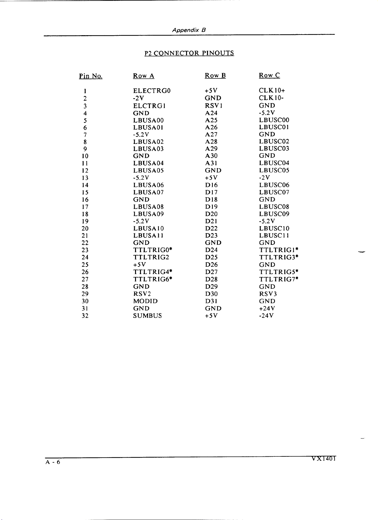
P2 CONNECTOR PINOUTS
Pin
No.
1
2
3
4
5
6
7
8
9
10
11
12
13
14
15
16
17
18
19
20
2
1
2 2
23
2 4
25
26
27
28
2 9
30
3
1
32
Row
A
Row B
ELECTRGO
-2v
ELCTRGl
GND
LBUSAOO
LBUSAOl
-5.2V
LBUSA02
LBUSA03
GND
LBUSA04
LBUSAO5
-5.2V
LBUSA06
LBUSA07
GND
LBUSA08
LBUSA09
-5.2V
LBUSAIO
LBUSA 1 1
GND
TTLTRIGO*
TTLTRIG2
+5v
TTLTRIG4*
TTLTRIG6*
GND
RSV2
MODID
GND
SUMBUS
+5v
GND
RSV
1
A24
A25
A26
A27
A28
A29
A30
A3 1
GND
+5v
Dl6
D 17
D
18
D
19
D20
D2 1
D22
D23
GND
D24
D25
D26
D27
D28
D29
D30
D3 1
GND
+5v
Row
C
CLK 10+
CLK
10-
GND
-5.2V
LBUSCOO
LBUSCO
1
GND
LBUSC02
LBUSC03
GND
LBUSC04
LBUSCO5
-2v
LBUSC06
LBUSC07
GND
LBUSCO8
LBUSC09
-5.2V
LBUSC10
LBUSC11
GND
TTLTRIGI*
TTLTRIG3*
GND
TTLTRIGS*
TTLTRIG7*
GND
r5v3
GND
+24V
-24V
Artisan Technology Group - Quality Instrumentation ... Guaranteed | (888) 88-SOURCE | www.artisantg.com
Page 34

Appendix
Power Budget Worksheet
The system integrator must use the power budget worksheet to determine the
operating parameters
it.
of
the card cage and any instrument modules installed in
C
Slot
POWER
Card No. +5V -5V +12V +24V -12V -24V
No.
(WATTS
)
-2V
I
watts's10t
(40 max)
User
TOTAL
570
total
--
rnax
Artisan Technology Group - Quality Instrumentation ... Guaranteed | (888) 88-SOURCE | www.artisantg.com
max max max max
max
1
570max
Page 35

Artisan Technology Group - Quality Instrumentation ... Guaranteed | (888) 88-SOURCE | www.artisantg.com
Page 36

Appendix
Servicing
I
WARNING
C
These servicing instructions are for use by quali jied personnel
only. To reduce the risk of electric shock, do not perform any
servicing other than that contained in the operating instructions
unless you are qualified to do so.
D
Adjusting
Power
If the power supplies need to be adjusted, refer to the drawing below and the
VX1401
procedure:
1.
2.
3. Place the chassis back upright and remove the fan plate (RP
4.
5.
Supply
Exploded Mechanical Assembly drawing and use the following
Remove the top and bottom covers as described in the
Disassembly
Remove the three screws (PSE
(PSI) to the chassis. These screws are on the bottom of the chassis, and are
easily accessed by tipping the chassis on its left side (as viewed from the
front).
on by nine screws (CCE 126-134). The fan plate will swing to the left.
Remove the five screws holding the baffle plate (BP2) on the power
supplies.
The
5V
to the right. The adjustment pots for both power supplies are now
accessible. Refer to the drawings below for their locations.
section.
4,
5,
and
6)
holding the
power supply may be lifted over the lip of the chassis and swung
NOTE.
Assembly and
5V
power supply
1). It is held
There must be at least a
supply. The backplane draws about
an additional load of at least
This can usually be met by a slot
other module.
Re-assemble the unit by reversing the above steps.
Artisan Technology Group - Quality Instrumentation ... Guaranteed | (888) 88-SOURCE | www.artisantg.com
5.5
amp load on the
1.25
4.25
amps is needed.
0
module and one
+5V
amps, so
Page 37

Appendix
D
The adjustment for each supply voltage is independent, and may be adjusted
without affecting the other supplies.
The -12V supply has no adjustment. The
VXI
Specification and factory adjustments for each supply are as shown:
Power
VXI
Spec. Factory Adjustment
supply Min. Max. Min. Max.
+5 +4.875 +5.250 +5.100 +5.200
*
The -12V supply has no adjustment.
Artisan Technology Group - Quality Instrumentation ... Guaranteed | (888) 88-SOURCE | www.artisantg.com
Page 38

Appendix
D
Selecting Cooling
In some operating environments, it may be necessary to have the VX140l's
cooling fans running at full speed all the time. The VX1401 has a two-position
Fan Speed slide switch inside the mainframe. The switch is located in the power
supply bay, on the right side (referenced from the front of the mainframe)
above the power supply cooling fan. The fans are set to variable speed when the
slide switch is in the UP position, and to full speed when the switch is in the
Cleaning
DOWN
Unplug the VX1401 from the electrical outlet before setting the Fan Speed
switch.
Air Filters
Removal
The main filter can be removed from either the front or side of the mainframe.
To remove the filter from the front, a
are required.
position.
1.
Fan
Speed
#2
Phillips and a flat blade screwdriver
Remove any modules or blank filler panels covering slot
6.
Remove the small slotted screw that holds the rail's center support
2.
standoff in place. Be sure to keep the small lock washer from under
the screw.
Remove the
3.
the mainframe. The filter can now be slid out the front of the
mainframe.
To remove the filter from the side:
Remove the two slotted screws in the filter support bracket located
1.
on the left side of the mainframe (referenced from the front).
Remove the bracket for the filter support.
2.
and can be removed from the slot on the left side of the mainframe.
Be careful not to over-tighten the two slotted screws when reinstalling the bracket.
To remove the filter of the power supply's fan, use a flat bladed screwdriver
and snap the plastic grill out of the filter housing.
Cleaning
Clean both filters with mild soap and water.
re-installing them and using the mainframe.
6-32
flat screw that holds the standoff from underneath
The filter will drop down
Bc
sure the filters are dry before
Artisan Technology Group - Quality Instrumentation ... Guaranteed | (888) 88-SOURCE | www.artisantg.com
Page 39
Appendix
D
Assembly
And
Disassembly
The VX1401 is shipped fully assembled.
assembly included here are for maintenance and repair purposes only.
schematic diagram that may also be used as a reference is included with this
manual.
I
WARNING
The procedures for disassembly and
A
I
Unplug the
ourlet before removing or installing the power
supplies. Severe electrical shock resulting in
personal injury may otherwise occur.
The VX1401 is designed so that one person can disassemble the mainframe. To
begin disassembly, remove the mainframe from the storage unit (see the Rack
Mounting section).
only tools required are a
screwdriver. To assemble the mainframe simply reverse these steps.
Removing the
Top Cover
VX1401
Place the mainframe on a large, clean work surface. The
Main frame from the electrical
#2
Phillips-head screwdriver and a flat bladed
NOTE:
Do NOT loosen or remove the four screws of the
power supply fan on the right side of the cage.
Loosen, but do not remove, the four screws that hold the left side rail to
the left side of the mainframe.
side rail to the right side of the mainframe, and remove the right side rail.
If the bottom of the mainframe is to be removed, the side rails may be
removed entirely.
Remove the five screws on each side of the top cover of the mainframe.
Remove the six screws on the top of the top cover of the mainframe.
Carefully pull the top cover up and toward the rear of the mainframe
until it clears the inner cage and set it to the side where it will not be
scratched or damaged. The right lower rear of the top cover (as viewed
from the front) needs to be pulled out to clear the power supply fan filter.
Removina the Bottom Cover
First remove the top cover.
1.
Remove the four screws that hold the right
Remove the left slide rail and turn the unit over so that it is resting on its
2.
inner cage.
Artisan Technology Group - Quality Instrumentation ... Guaranteed | (888) 88-SOURCE | www.artisantg.com
Page 40

Appendix
Remove the four screws on each side of the bottom cover of the
3.
D
mainframe.
Remove the one screw on the bottom of the mainframe.
4.
Carefully pull the bottom cover up and toward the rear of the mainframe
5.
until it clears the inner cage, and set it to the side, where it will not be
scratched or damaged.
At this point, the mainframe is disassembled enough to accomplish any
maintenance required.
Artisan Technology Group - Quality Instrumentation ... Guaranteed | (888) 88-SOURCE | www.artisantg.com
Page 41

Appendix
D
Artisan Technology Group - Quality Instrumentation ... Guaranteed | (888) 88-SOURCE | www.artisantg.com
Page 42

Appendix
E
(Option
1
M)
MATE
Applications
Option 1M: MATE Compatible Mainframe
If the
VX1401
Mainframe is ordered with Option lM, MATE Compatible, the
card cage is delivered with the following modifications:
Aluminum Rack Slides that meet or exceed the MATE guidelines.
MATE Butch Plate with provisions for mounting the
IEEE-488
connector
and the
DFI
BNC
connector.
Artisan Technology Group - Quality Instrumentation ... Guaranteed | (888) 88-SOURCE | www.artisantg.com
Page 43
Appendix
E
Artisan Technology Group - Quality Instrumentation ... Guaranteed | (888) 88-SOURCE | www.artisantg.com
Page 44

Appendix
F
Replaceable
Q~Y.
per
Descri~tion Part Number Chassis
Top Cover
Bottom Cover
Line Fuse (5A)
Line Fuse (7A)
(1
Internal Line Fuse
Rack Ear (right)
Rack
Ear
(left)
Front Handle
Rear Handle
Rear Fan
Side Fan
Chassis Air Filter
Side Fan Filter
5A)
Parts
Artisan Technology Group - Quality Instrumentation ... Guaranteed | (888) 88-SOURCE | www.artisantg.com
Page 45

Appendix
F
Artisan Technology Group - Quality Instrumentation ... Guaranteed | (888) 88-SOURCE | www.artisantg.com
Page 46

Appendix
G
Options
The following options are available for the VX1401:
Plugs
Option A1 220V Euro plug
Option A2 240V
UK
plug
Option A3 240V Aust. plug
Option
A4
240V N. Amer. plug
Option A5 220V Swiss plug
Mainframes are shipped with the required power cords as ordered
by
the
customer. The available power cords are shown in
Power
Cords.
Option
01
Delete
Rack
Slide, Add Trim: removes the standard rack slides and replaces
them with Trim Plates, one on each side of the mainframe. A VX1401 Option 01
is not intended to be mounted in a standard NEMA rack.
Artisan Technology Group - Quality Instrumentation ... Guaranteed | (888) 88-SOURCE | www.artisantg.com
Page 47

Appendix
G
Artisan Technology Group - Quality Instrumentation ... Guaranteed | (888) 88-SOURCE | www.artisantg.com
Page 48

Glossary
The terms in this glossary are defined as used in the VXIbus System. Although
some of these terms may have different meanings in other systems, it is
important to use these definitions in VXIbus applications.
Terms which apply
only to a particular instrument module are noted. Not all terms appear in every
manual.
Term Definition
Accessed
Indicator
ACFAIL*
A-Size Card
Asynchronous
Communication
Backplane
B-Size Card
Bus Arbitration
Bus Timer
Client
An amber LED indicator that lights when the module identity
is selected by the Resource Manager module, and flashes during
any 1/0 operation for the module.
A VMEbus backplane line that is asserted under these
conditions:
1) by the card cage Power Supply when a power
failure has occurred (either ac line source or power supply
malfunction), or
2)
by the front panel ON/STANDBY switch
when switched to STANDBY.
A
VXIbus instrument module that is 100.0 by 160 mm by 20.32
mm
(3.9
by 6.3 in by 0.8 in), the same size as a VMEbus single-
height short module.
Communications that occur outside the normal "command-
response" cycle. Such communications have higher priority
than synchronous communication.
The printed circuit board that is mounted in a VXIbus card
cage to provide the interface between VXIbus modules and
between those modules and the external system.
A VXIbus instrument module that is 233.4 by 160 mm by 20.32
mm (9.2 by 6.3 in by 0.8 in), the same size as a VMEbus double-
height short module.
In the VMEbus interface, a system for resolving contention for
service among VMEbus Master devices on the VMEbus.
A functional module that measures the duration of each data
transfer on the Data Transfer Bus (DTB) and terminates the
DTB cycle if the duration is excessive.
Without the termination
capability of this module, a Bus Master attempt to transfer data
to or from a non-existent Slave location could result in an
infinitely long wait for the Slave response.
In shared memory protocol (SMP), that half of an SMP channel
that does not control the shared memory buffers.
Artisan Technology Group - Quality Instrumentation ... Guaranteed | (888) 88-SOURCE | www.artisantg.com
Page 49

CLKlO
CLK 100
Glossarv
A
10-MHz, *lo0 ppm, individually buffered (to each module
ECL
slot), differential
system clock that is sourced from Slot 0
and distributed to Slots 1-12 on P2. It is distributed to each
module slot as a single source, single destination signal with a
8
matched delay of under
A
100-MHz, i100 ppm, individually buffered (to each module
slot), differential
ECL
and distributed to Slots 1-12 on P3.
ns.
system clock that is sourced from Slot 0
It is distributed to each
module slot in synchronous with CLKlO as a single source,
single destination signal with a maximum system timing skew
8
of 2 ns, and a maximum total delay of
ns.
Commander
Command
Communication
Registers
Configuration
Registers
In the VXIbus interface, a device that controls another device
(a
servant). A commander may be a servant of another
commander.
A directive to a device. There are three types of commands:
In Word Serial Protocol, a 16-bit imperative to a servant from
its commander.
In Shared Memory Protocol, a 16-bit imperative from a client to
a server, or vice versa.
In a Message, an ASCII-coded, multi-byte directive to any
receiving device.
In word serial protocol, a set of device registers that are
accessible to the commander of the device. Such registers are
used for inter-device communications, and are required on all
VXIbus message-based devices.
A set of registers that allow the system to identify a (module)
device type, model, manufacturer, address space, and memory
requirements. In order to support automatic system and
memory configuration, the VXIbus standard specifies that all
VXIbus devices have a set of such registers, all accessible from
PI on the VMEbus.
--C
C-Size Card
A VXIbus instrument module that is 340.0 by 233.4 mm by
30.48 mm (13.4 by 9.2 in by 1.2 in).
Custom Device
A
special-purpose VXIbus device that has configuration
registers so as to be identified by the system and to allow for
definition of future device types to support further levels of
compatibility.
Data Transfer
Bus
One of four buses on the VMEbus backplane. The
Data
Transfer Bus allows Bus Masters to direct the transfer of
binary data between Masters and Slaves.
DC
SUPPLIES
A
Indicator
red LED indicator that illuminates when a
DC
power fault is
detected on the backplane.
Artisan Technology Group - Quality Instrumentation ... Guaranteed | (888) 88-SOURCE | www.artisantg.com
Page 50

Device Specific
Protocol
Glossary
A
protocol for communication with a device that is not defined
in the VXIbus specification.
D-Size Card
DTB
DTB Arbiter
A VXIbus instrument module that is 340.0 by 366.7 mm by
(1
30.48 mm
3.4 x 14.4 in x 1.2 in).
See Data Transfer Bus.
A
functional module that accepts bus requests from Requester
modules and grants control of the DTB to one Requester at a
time.
DUT
ECLTRG
Device Under Test.
Six single-ended ECL trigger lines (two on
that function as inter-module timing resources, and that are
bussed across the VXIbus subsystem backplane. Any module,
including the Slot 0 module, may drive and receive information
from these lines. These lines have an impedance of 50 ohms;
the asserted state is logical High.
Embedded
Address
An address in a communications protocol in which the
destination of the message is included in the message.
ESTST
Extended
STart/STop protocol; used to synchronize VXIbus
modules.
Extended
Self Test
Any self test or diagnostic power-up routine that executes after
the initial kernel self test program.
External System
Controller
The host computer or other external controller that exerts
overall control over VXIbus operations.
FAILED
Indicator
A red LED indicator that lights when a device on the
has detected an internal fault. This might result in the
assertion of the SYSFAIL* line.
IACK Daisy Chain
Driver The circuit that drives the
daisy chain line that runs continuously through all installed
modules or through jumpers across the backplane.
P2
and four on
VXIbus
VMEbus Interrupt Acknowledge
P3)
ID-ROM
An NVRAM storage area that provides for non-volatile storage
of diagnostic data.
Instrument
Module
A plug-in printed circuit board, with associated components
and shields, that may be installed in a VXIbus card cage. An
instrument module may contain more than one device. Also,
one device may require more than one instrument module.
Interface
Device A VXIbus device that provides one or more interfaces to
external equipment.
Artisan Technology Group - Quality Instrumentation ... Guaranteed | (888) 88-SOURCE | www.artisantg.com
Page 51

Interrupt
Handler
Glossary
A functional module that detects interrupt requests generated
by Interrupters and responds to those requests by requesting
status and identity information.
Interrupter
IRQ
Local Bus
Local Controller The instrument module that performs system control and
Local Processor The processor on an instrument module.
Logical Address The smallest functional unit recognized by a
Mainframe
Memory Device
A device capable of asserting VMEbus interrupts and
performing the interrupt acknowledge sequence.
The Interrupt
line that is asserted by an Interrupter to signify to the
controller that a device on the bus requires service by the
controller.
A
daisy-chained bus that connects adjacent VXIbus slots.
external interface functions for the instrument modules in a
VXIbus card cage or several card cages. See Resource Manager.
is often used to identify a particular module.
Card Cage For example, the Tektronix VX1401 Card Cage, an
A
storage element (such as bubble memory, RAM, and ROM)
that has configuration registers and memory attributes (such as
type and access time).
ReQuest signal, which is the VMEbus interrupt
VXlbus system. It
13
operable housing that includes
instrument module slots.
C-size VXIbus
-
Message
Message Based
Device
MODID Lines
Physical
Address
Power Monitor
A
series of data bytes that are treated as a single
communication, with a well defined terminator and message
body.
A
VXIbus device that supports VXI configuration and
communication registers. Such devices support the word serial
protocol, and possibly other message-based protocols.
Module/system identity lines.
The address assigned to a backplane slot during an access.
A
device that monitors backplane power and reports fault
conditions.
The top-most backplane connector for a given module slot in a
vertical card cage such as the Tektronix VX1400. The left-most
backplane connector for a given slot in a horizontal card cage.
a
The bottom backplane connector for
vertical C-size card cage such as the VX1400; or the middle
given module slot in a
Artisan Technology Group - Quality Instrumentation ... Guaranteed | (888) 88-SOURCE | www.artisantg.com
Page 52

Glossary
backplane connector for a given module slot in a vertical D-size
VX
card cage such as the
1500.
The bottom backplane connector for a given module slot in a
vertical D-size card cage such as the Tektronix VX1500.
Query
READY
Indicator
Register Based
Device
Requester
Resource
Manager
Self
Calibration
A form of command that allows for inquiry to obtain status or
data.
LED
A green
indicator that lights when the power-up
diagnostic routines have been completed successfully. An
internal failure or failure of +5-volt power will extinguish this
indicator.
A VXIbus device that supports VXI register maps, but not high
level VXIbus communication protocols; includes devices that
are register-based servant elements.
A functional module that resides on the same module as a
Master or Interrupt Handler and requests use of the DTB
whenever its Master or Interrupt Handler requires it.
A VXIbus device that provides configuration management
services such as address map configuration, determining system
hierarchy, allocating shared system resources, performing
system self test diagnostics, and initializing system
commanders.
A
routine that verifies the basic calibration of the instrument
module circuits, and adjusts this calibration to compensate for
short- and long-term variables.
Self Test
Servant
Server
Shared Memory
Protocol
0
Slot
Controller
0 Module
Slot
SMP
A set of routines that determine if the instrument module
circuits will perform according to a given set of standards.
A
self test routine is performed upon power-up.
A VXIbus message-based device that is controlled by a
commander.
A shared memory device that controls the shared memory
buffers used in a given Shared Memory Protocol channel.
A communications protocol that uses a block of memory that is
accessible to both client and server. The memory block
operates as a message buffer for communications.
0
See Slot
A
VXIbus device that provides the minimum VXIbus slot
services to slots 1 through
Module. Also see Resource Manager.
12
(CLKIO
and the module identity
0
lines), but that may provide other services such as CLK100,
SYNC100, STARBUS, and trigger control.
See Shared Memory Protocol.
Artisan Technology Group - Quality Instrumentation ... Guaranteed | (888) 88-SOURCE | www.artisantg.com
Page 53

STARX
Glossary
(2)
Two
bi-directional,
50
ohm, differential
ECL
lines that
provide for inter-module asynchronous communication. These
pairs of timed and matched delay lines connect slot 0 and each
1
of slots
through 12 in a card cage. The delay between slots is
less than 5 nanoseconds, and the lines are well matched for
timing skew.
STARY
Two (2) bi-directional, 50 ohm, differential ECL lines that
provide for inter-module asynchronous communication. These
0
pairs of timed and matched delay lines connect slot
of slots
1
through
12
in a card cage. The delay between slots is
and each
less than 5 nanoseconds, and the lines are well matched for
timing skew.
STST
SYNC100
STart/STop protocol; used to synchronize modules.
A
Slot 0 signal that is used to synchronize multiple devices with
respect to a given rising edge of CLK100. These signals are
individually buffered and matched to less than 2ns of skew.
Synchronous
Communications A communications system that follows the "command-response"
cycle model. In this model, a device issues a command to
another device; the second device executes the command; then
returns a response. Synchronous commands are executed in the
order received.
SYSFAIL*
A
signal line on the VMEbus that is used to indicate a failure
by a device. The device that fails asserts this line.
System Clock
Driver
A
functional module that provides a 16-MHz timing signal on
the Utility Bus.
System
Hierarchy
The tree structure of the
commander/servant relationships of
all devices in the system at a given time. In the VXIbus
A
structure, each servant has a commander.
commander may
also have a commander.
Test Monitor
Test Program
Test System
TTLTRG
VXIbus
Subsystem
An executive routine that is responsible for executing the self
tests, storing any errors in the ID-ROM, and reporting such
errors to the Resource Manager.
A program, executed on the system controller, that controls the
execution of tests within the test system.
A
collection of hardware and software modules that operate in
concert to test a target DUT.
Open collector TTL lines used for inter-module timing and
communication.
One card cage with modules installed. The installed modules
a
include one module that performs slot
0 functions and
given
complement of instrument modules. The subsystem may also
include a Resource Manager.
Artisan Technology Group - Quality Instrumentation ... Guaranteed | (888) 88-SOURCE | www.artisantg.com
Page 54

Glossary
Word Serial
Protocol
A
VXIbus word oriented, bi-directional, serial protocol for
communications between message-based devices (that is, devices
that include communication registers in addition to
configuration registers).
Word Serial
Communications Inter-device communications using the Word Serial Protocol.
WSP See Word Serial Protocol.
10-MHz Clock
A
10 MHz, i100 ppm timing reference. Also see CLK 10.
100-MHz Clock
A
100 MHz, *lo0 ppm clock synchronized with CLKIO. Also
see CLK
100.
488-TO-VXIbus
Interface
A message based device that provides for communication
between the
IEEE-488
bus and VXIbus instrument modules.
Artisan Technology Group - Quality Instrumentation ... Guaranteed | (888) 88-SOURCE | www.artisantg.com
Page 55

Artisan Technology Group - Quality Instrumentation ... Guaranteed | (888) 88-SOURCE | www.artisantg.com
Page 56

Artisan Technology Group - Quality Instrumentation ... Guaranteed | (888) 88-SOURCE | www.artisantg.com
Page 57

Artisan Technology Group - Quality Instrumentation ... Guaranteed | (888) 88-SOURCE | www.artisantg.com
Page 58
Artisan Technology Group is your source for quality
new and certied-used/pre-owned equipment
• FAST SHIPPING AND
DELIVERY
• TENS OF THOUSANDS OF
IN-STOCK ITEMS
• EQUIPMENT DEMOS
• HUNDREDS OF
MANUFACTURERS
SUPPORTED
• LEASING/MONTHLY
RENTALS
• ITAR CERTIFIED
SECURE ASSET SOLUTIONS
SERVICE CENTER REPAIRS
Experienced engineers and technicians on staff
at our full-service, in-house repair center
Instra
Remotely inspect equipment before purchasing with
our interactive website at www.instraview.com
Contact us: (888) 88-SOURCE | sales@artisantg.com | www.artisantg.com
SM
REMOTE INSPECTION
View
WE BUY USED EQUIPMENT
Sell your excess, underutilized, and idle used equipment
We also offer credit for buy-backs and trade-ins
www.artisantg.com/WeBuyEquipment
LOOKING FOR MORE INFORMATION?
Visit us on the web at www.artisantg.com for more
information on price quotations, drivers, technical
specications, manuals, and documentation
 Loading...