

Page 1

Service Manual
VM100 & VM101
Video Measurment Set
070-9288-02
This document supports firmware version 1.64
and above.
Warning
The servicing instructions are for use by qualified
personnel only. To avoid personal injury, do not
perform any servicing unless you are qualified to
do so. Refer to all safety summaries prior to
performing service.
Page 2

Copyright © T ektronix, Inc. All rights reserved.
T ektronix products are covered by U.S. and foreign patents, issued and pending. Information in this publication supercedes
that in all previously published material. Specifications and price change privileges reserved.
Printed in the U.S.A.
T ektronix, Inc., P.O. Box 1000, Wilsonville, OR 97070–1000
TEKTRONIX and TEK are registered trademarks of T ektronix, Inc.
Page 3

WARRANTY
T ektronix warrants that the products that it manufactures and sells will be free from defects in materials and workmanship
for a period of one (1) year from the date of shipment. If a product proves defective during this warranty period, T ektronix,
at its option, either will repair the defective product without charge for parts and labor, or will provide a replacement in
exchange for the defective product.
In order to obtain service under this warranty, Customer must notify Tektronix of the defect before the expiration of the
warranty period and make suitable arrangements for the performance of service. Customer shall be responsible for
packaging and shipping the defective product to the service center designated by T ektronix, with shipping charges prepaid.
T ektronix shall pay for the return of the product to Customer if the shipment is to a location within the country in which the
T ektronix service center is located. Customer shall be responsible for paying all shipping charges, duties, taxes, and any
other charges for products returned to any other locations.
This warranty shall not apply to any defect, failure or damage caused by improper use or improper or inadequate
maintenance and care. T ektronix shall not be obligated to furnish service under this warranty a) to repair damage resulting
from attempts by personnel other than T ektronix representatives to install, repair or service the product; b) to repair
damage resulting from improper use or connection to incompatible equipment; c) to repair any damage or malfunction
caused by the use of non-T ektronix supplies; or d) to service a product that has been modified or integrated with other
products when the effect of such modification or integration increases the time or difficulty of servicing the product.
THIS WARRANTY IS GIVEN BY TEKTRONIX IN LIEU OF ANY OTHER WARRANTIES, EXPRESS OR
IMPLIED. TEKTRONIX AND ITS VENDORS DISCLAIM ANY IMPLIED WARRANTIES OF
MERCHANTABILITY OR FITNESS FOR A PARTICULAR PURPOSE. TEKTRONIX’ RESPONSIBILITY TO
REP AIR OR REPLACE DEFECTIVE PRODUCTS IS THE SOLE AND EXCLUSIVE REMEDY PROVIDED TO
THE CUSTOMER FOR BREACH OF THIS WARRANTY. TEKTRONIX AND ITS VENDORS WILL NOT BE
LIABLE FOR ANY INDIRECT , SPECIAL, INCIDENTAL, OR CONSEQUENTIAL DAMAGES IRRESPECTIVE
OF WHETHER TEKTRONIX OR THE VENDOR HAS ADVANCE NOTICE OF THE POSSIBILITY OF SUCH
DAMAGES.
Page 4

Service Assurance
If you have not already purchased Service Assurance for this product, you may do so at any time during the product’s
warranty period. Service Assurance provides Repair Protection and Calibration Services to meet your needs.
Repair Protection extends priority repair services beyond the product’s warranty period; you may purchase up to three
years of Repair Protection.
Calibration Services provide annual calibration of your product, standards compliance and required audit documentation,
recall assurance, and reminder notification of scheduled calibration. Coverage begins upon registration; you may purchase
up to five years of Calibration Services.
Service Assurance Advantages
H Priced well below the cost of a single repair or calibration
H Avoid delays for service by eliminating the need for separate purchase authorizations from your company
H Eliminates unexpected service expenses
For Information and Ordering
For more information or to order Service Assurance, contact your T ektronix representative and provide the information
below . Service Assurance may not be available in locations outside the United States of America.
Name VISA or Master Card number and expiration
Company date or purchase order number
Address Repair Protection (1,2, or 3 years)
City , State, Postal code Calibration Services (1,2,3,4, or 5 years)
Country Instrument model and serial number
Phone Instrument purchase date
Page 5

Table of Contents
Specifications
Operating Information
General Safety Summary vii. . . . . . . . . . . . . . . . . . . . . . . . . . . . . . . . . . . .
Service Safety Summary ix. . . . . . . . . . . . . . . . . . . . . . . . . . . . . . . . . . . . .
Preface xi. . . . . . . . . . . . . . . . . . . . . . . . . . . . . . . . . . . . . . . . . . . . . . . . . . .
Related Manuals xi. . . . . . . . . . . . . . . . . . . . . . . . . . . . . . . . . . . . . . . . . . . . . . . . . .
Service Manual Conventions xi. . . . . . . . . . . . . . . . . . . . . . . . . . . . . . . . . . . . . . . .
Contacting T ektronix xii. . . . . . . . . . . . . . . . . . . . . . . . . . . . . . . . . . . . . . . . . . . . . .
Product Description 1–1. . . . . . . . . . . . . . . . . . . . . . . . . . . . . . . . . . . . . . . . . . . . . . .
Specification T ables 1–2. . . . . . . . . . . . . . . . . . . . . . . . . . . . . . . . . . . . . . . . . . . . . . .
T erms Used in Specifications 1–2. . . . . . . . . . . . . . . . . . . . . . . . . . . . . . . . . . . .
Performance Conditions 1–2. . . . . . . . . . . . . . . . . . . . . . . . . . . . . . . . . . . . . . . .
Electrical Specifications 1–3. . . . . . . . . . . . . . . . . . . . . . . . . . . . . . . . . . . . . . . . . . . .
Environmental Characteristics 1–5. . . . . . . . . . . . . . . . . . . . . . . . . . . . . . . . . . . . . . .
Safety Standards and Certification 1–6. . . . . . . . . . . . . . . . . . . . . . . . . . . . . . . . . . . .
Physical Characteristics 1–7. . . . . . . . . . . . . . . . . . . . . . . . . . . . . . . . . . . . . . . . . . . .
Remote Control Port 1–7. . . . . . . . . . . . . . . . . . . . . . . . . . . . . . . . . . . . . . . . . . . . . .
Theory of Operation
Installation 2–1. . . . . . . . . . . . . . . . . . . . . . . . . . . . . . . . . . . . . . . . . . . . . . . . . . . . . .
Power Source Requirements 2–1. . . . . . . . . . . . . . . . . . . . . . . . . . . . . . . . . . . . .
Operating Information 2–1. . . . . . . . . . . . . . . . . . . . . . . . . . . . . . . . . . . . . . . . . . . . .
Front Panel Buttons and LCD Display 2–2. . . . . . . . . . . . . . . . . . . . . . . . . . . . .
Menus 2–4. . . . . . . . . . . . . . . . . . . . . . . . . . . . . . . . . . . . . . . . . . . . . . . . . . . . . .
Rear Panel Connectors 2–6. . . . . . . . . . . . . . . . . . . . . . . . . . . . . . . . . . . . . . . . .
Power On Procedure 2–7. . . . . . . . . . . . . . . . . . . . . . . . . . . . . . . . . . . . . . . . . . .
Configuration 2–7. . . . . . . . . . . . . . . . . . . . . . . . . . . . . . . . . . . . . . . . . . . . . . . .
Logic Conventions 3–1. . . . . . . . . . . . . . . . . . . . . . . . . . . . . . . . . . . . . . . . . . . . . . . .
Block Level Description 3–1. . . . . . . . . . . . . . . . . . . . . . . . . . . . . . . . . . . . . . . . . . .
DC Restore 3–1. . . . . . . . . . . . . . . . . . . . . . . . . . . . . . . . . . . . . . . . . . . . . . . . . .
Sync Stripper 3–1. . . . . . . . . . . . . . . . . . . . . . . . . . . . . . . . . . . . . . . . . . . . . . . . .
Gain, DC Offset, and Filtering 3–2. . . . . . . . . . . . . . . . . . . . . . . . . . . . . . . . . . .
Phase Lock Loop 3–2. . . . . . . . . . . . . . . . . . . . . . . . . . . . . . . . . . . . . . . . . . . . . .
Analog-to-Digital Converter 3–2. . . . . . . . . . . . . . . . . . . . . . . . . . . . . . . . . . . . .
Digital Signal Processor 3–2. . . . . . . . . . . . . . . . . . . . . . . . . . . . . . . . . . . . . . . .
Acquisition Control 3–2. . . . . . . . . . . . . . . . . . . . . . . . . . . . . . . . . . . . . . . . . . . .
Host Processor and Memory 3–2. . . . . . . . . . . . . . . . . . . . . . . . . . . . . . . . . . . . .
Remote Interface (RS232) 3–2. . . . . . . . . . . . . . . . . . . . . . . . . . . . . . . . . . . . . .
Front Panel 3–2. . . . . . . . . . . . . . . . . . . . . . . . . . . . . . . . . . . . . . . . . . . . . . . . . .
LCD Display 3–2. . . . . . . . . . . . . . . . . . . . . . . . . . . . . . . . . . . . . . . . . . . . . . . . .
Power Supply 3–2. . . . . . . . . . . . . . . . . . . . . . . . . . . . . . . . . . . . . . . . . . . . . . . .
Detailed Circuit Description 3–3. . . . . . . . . . . . . . . . . . . . . . . . . . . . . . . . . . . . . . . .
VM100 & VM101 Service Manual
i
Page 6

Table of Contents
Performance Verification
General Information 4–1. . . . . . . . . . . . . . . . . . . . . . . . . . . . . . . . . . . . . . . . . . . . . . .
Prerequisites 4–2. . . . . . . . . . . . . . . . . . . . . . . . . . . . . . . . . . . . . . . . . . . . . . . . . . . . .
Equipment Requirements 4–2. . . . . . . . . . . . . . . . . . . . . . . . . . . . . . . . . . . . . . . . . . .
T est Record 4–3. . . . . . . . . . . . . . . . . . . . . . . . . . . . . . . . . . . . . . . . . . . . . . . . . . . . . .
Performance Verification Procedure 4–4. . . . . . . . . . . . . . . . . . . . . . . . . . . . . . . . . .
DC Restore 3–3. . . . . . . . . . . . . . . . . . . . . . . . . . . . . . . . . . . . . . . . . . . . . . . . . .
Sync Stripper 3–4. . . . . . . . . . . . . . . . . . . . . . . . . . . . . . . . . . . . . . . . . . . . . . . . .
Gain, DC Offset, and Filtering 3–4. . . . . . . . . . . . . . . . . . . . . . . . . . . . . . . . . . .
Phase Lock Loop 3–6. . . . . . . . . . . . . . . . . . . . . . . . . . . . . . . . . . . . . . . . . . . . . .
A/D Converter 3–7. . . . . . . . . . . . . . . . . . . . . . . . . . . . . . . . . . . . . . . . . . . . . . . .
Digital Signal Processor (DSP) 3–8. . . . . . . . . . . . . . . . . . . . . . . . . . . . . . . . . . .
Acquisition Control 3–9. . . . . . . . . . . . . . . . . . . . . . . . . . . . . . . . . . . . . . . . . . . .
Host Processor and Memory 3–10. . . . . . . . . . . . . . . . . . . . . . . . . . . . . . . . . . . . .
Remote Interface (RS232) 3–11. . . . . . . . . . . . . . . . . . . . . . . . . . . . . . . . . . . . . .
Front Panel 3–12. . . . . . . . . . . . . . . . . . . . . . . . . . . . . . . . . . . . . . . . . . . . . . . . . .
LCD Display 3–12. . . . . . . . . . . . . . . . . . . . . . . . . . . . . . . . . . . . . . . . . . . . . . . . .
Power Supply 3–12. . . . . . . . . . . . . . . . . . . . . . . . . . . . . . . . . . . . . . . . . . . . . . . .
Purpose 4–1. . . . . . . . . . . . . . . . . . . . . . . . . . . . . . . . . . . . . . . . . . . . . . . . . . . . .
T est Interval 4–1. . . . . . . . . . . . . . . . . . . . . . . . . . . . . . . . . . . . . . . . . . . . . . . . .
Initial Setup 4–4. . . . . . . . . . . . . . . . . . . . . . . . . . . . . . . . . . . . . . . . . . . . . . . . . .
Configure the Video Measurement Set 4–4. . . . . . . . . . . . . . . . . . . . . . . . . . . . .
Signal Identification T est 4–5. . . . . . . . . . . . . . . . . . . . . . . . . . . . . . . . . . . . . . .
Differential Phase Test 4–5. . . . . . . . . . . . . . . . . . . . . . . . . . . . . . . . . . . . . . . . .
Differential Gain Test 4–5. . . . . . . . . . . . . . . . . . . . . . . . . . . . . . . . . . . . . . . . . .
Sync Amplitude T est 4–5. . . . . . . . . . . . . . . . . . . . . . . . . . . . . . . . . . . . . . . . . . .
Burst Amplitude T est 4–6. . . . . . . . . . . . . . . . . . . . . . . . . . . . . . . . . . . . . . . . . .
Bar Amplitude T est 4–6. . . . . . . . . . . . . . . . . . . . . . . . . . . . . . . . . . . . . . . . . . . .
2T K-factor Test 4–6. . . . . . . . . . . . . . . . . . . . . . . . . . . . . . . . . . . . . . . . . . . . . .
Chrominance-to-Luminance Delay T est 4–6. . . . . . . . . . . . . . . . . . . . . . . . . . . .
Chrominance-to-Luminance Gain T est 4–7. . . . . . . . . . . . . . . . . . . . . . . . . . . . .
Luminance Nonlinearity T est 4–7. . . . . . . . . . . . . . . . . . . . . . . . . . . . . . . . . . . .
Group Delay T est 4–7. . . . . . . . . . . . . . . . . . . . . . . . . . . . . . . . . . . . . . . . . . . . .
Frequency Response T est 4–8. . . . . . . . . . . . . . . . . . . . . . . . . . . . . . . . . . . . . . .
Adjustment Procedures
ii
General Information 5–1. . . . . . . . . . . . . . . . . . . . . . . . . . . . . . . . . . . . . . . . . . . . . . .
Purpose 5–1. . . . . . . . . . . . . . . . . . . . . . . . . . . . . . . . . . . . . . . . . . . . . . . . . . . . .
Adjustment Interval 5–1. . . . . . . . . . . . . . . . . . . . . . . . . . . . . . . . . . . . . . . . . . .
Requirements 5–2. . . . . . . . . . . . . . . . . . . . . . . . . . . . . . . . . . . . . . . . . . . . . . . . . . . .
Personnel 5–2. . . . . . . . . . . . . . . . . . . . . . . . . . . . . . . . . . . . . . . . . . . . . . . . . . . .
Warmup Period 5–2. . . . . . . . . . . . . . . . . . . . . . . . . . . . . . . . . . . . . . . . . . . . . . .
Access 5–2. . . . . . . . . . . . . . . . . . . . . . . . . . . . . . . . . . . . . . . . . . . . . . . . . . . . . .
Required T est Equipment 5–2. . . . . . . . . . . . . . . . . . . . . . . . . . . . . . . . . . . . . . .
Adjustment Procedure 5–3. . . . . . . . . . . . . . . . . . . . . . . . . . . . . . . . . . . . . . . . . . . . .
Interrupting the Adjustments 5–3. . . . . . . . . . . . . . . . . . . . . . . . . . . . . . . . . . . .
Performing the Adjustments 5–3. . . . . . . . . . . . . . . . . . . . . . . . . . . . . . . . . . . . .
VM100 & VM101 Service Manual
Page 7

Maintenance
Table of Contents
Preventing ESD 6–1. . . . . . . . . . . . . . . . . . . . . . . . . . . . . . . . . . . . . . . . . . . . . . . . . .
Battery Disposal 6–2. . . . . . . . . . . . . . . . . . . . . . . . . . . . . . . . . . . . . . . . . . . . . . . . . .
Inspection and Cleaning 6–3. . . . . . . . . . . . . . . . . . . . . . . . . . . . . . . . . . . . . . . . . . . .
General Care 6–3. . . . . . . . . . . . . . . . . . . . . . . . . . . . . . . . . . . . . . . . . . . . . . . . .
Inspection and Cleaning Procedures 6–3. . . . . . . . . . . . . . . . . . . . . . . . . . . . . . .
Removal and Replacement Procedures 6–7. . . . . . . . . . . . . . . . . . . . . . . . .
Preparation 6–7. . . . . . . . . . . . . . . . . . . . . . . . . . . . . . . . . . . . . . . . . . . . . . . . . . . . . .
Summary of Procedures 6–7. . . . . . . . . . . . . . . . . . . . . . . . . . . . . . . . . . . . . . . . . . . .
T ools Required 6–8. . . . . . . . . . . . . . . . . . . . . . . . . . . . . . . . . . . . . . . . . . . . . . . . . . .
T op Cover 6–8. . . . . . . . . . . . . . . . . . . . . . . . . . . . . . . . . . . . . . . . . . . . . . . . . . . . . . .
Front Panel 6–9. . . . . . . . . . . . . . . . . . . . . . . . . . . . . . . . . . . . . . . . . . . . . . . . . . . . . .
Main Board 6–11. . . . . . . . . . . . . . . . . . . . . . . . . . . . . . . . . . . . . . . . . . . . . . . . . . . . . .
Power Supply 6–13. . . . . . . . . . . . . . . . . . . . . . . . . . . . . . . . . . . . . . . . . . . . . . . . . . . .
LCD Board 6–14. . . . . . . . . . . . . . . . . . . . . . . . . . . . . . . . . . . . . . . . . . . . . . . . . . . . . .
Lithium Battery 6–16. . . . . . . . . . . . . . . . . . . . . . . . . . . . . . . . . . . . . . . . . . . . . . . . . .
Troubleshooting 6–17. . . . . . . . . . . . . . . . . . . . . . . . . . . . . . . . . . . . . . . . . . . .
Equipment Required 6–18. . . . . . . . . . . . . . . . . . . . . . . . . . . . . . . . . . . . . . . . . . . . . . .
T esting the Lithium Battery 6–18. . . . . . . . . . . . . . . . . . . . . . . . . . . . . . . . . . . . . . . . .
Power Supply Limits 6–19. . . . . . . . . . . . . . . . . . . . . . . . . . . . . . . . . . . . . . . . . . . . . .
Troubleshooting the main board (A2) 6–20. . . . . . . . . . . . . . . . . . . . . . . . . . . . . . . . .
Examples of Analog Signal Measurements 6–21. . . . . . . . . . . . . . . . . . . . . . . . .
Phase Lock and DSP Diagnostic LEDs and Key Signals 6–25. . . . . . . . . . . . . . .
ACQ:SHOW Command 6–28. . . . . . . . . . . . . . . . . . . . . . . . . . . . . . . . . . . . . . . .
Troubleshooting the VM140 or VM141 System 6–30. . . . . . . . . . . . . . . . . . . . .
Repackaging Instructions 6–33. . . . . . . . . . . . . . . . . . . . . . . . . . . . . . . . . . . .
Packaging 6–33. . . . . . . . . . . . . . . . . . . . . . . . . . . . . . . . . . . . . . . . . . . . . . . . . . . . . . .
Storage 6–33. . . . . . . . . . . . . . . . . . . . . . . . . . . . . . . . . . . . . . . . . . . . . . . . . . . . . . . . .
Options
Standard Accessories 7–1. . . . . . . . . . . . . . . . . . . . . . . . . . . . . . . . . . . . . . . . . . . . . .
Optional Accessories 7–1. . . . . . . . . . . . . . . . . . . . . . . . . . . . . . . . . . . . . . . . . . . . . .
Options 7–2. . . . . . . . . . . . . . . . . . . . . . . . . . . . . . . . . . . . . . . . . . . . . . . . . . . . . . . . .
Replaceable Electrical Parts
Parts Ordering Information 8–1. . . . . . . . . . . . . . . . . . . . . . . . . . . . . . . . . . . . . . . . .
Using the Replaceable Electrical Parts List 8–1. . . . . . . . . . . . . . . . . . . . . . . . . . . . .
Diagrams
Symbols 9–1. . . . . . . . . . . . . . . . . . . . . . . . . . . . . . . . . . . . . . . . . . . . . . . . . . . . . . . .
Component Values 9–1. . . . . . . . . . . . . . . . . . . . . . . . . . . . . . . . . . . . . . . . . . . . . . . .
Graphic Items and Special Symbols Used in This Manual 9–2. . . . . . . . . . . . . . . . .
Component Locator Diagrams 9–2. . . . . . . . . . . . . . . . . . . . . . . . . . . . . . . . . . . . . . .
Replaceable Mechanical Parts
Parts Ordering Information 10–1. . . . . . . . . . . . . . . . . . . . . . . . . . . . . . . . . . . . . . . . .
Using the Replaceable Mechanical Parts List 10–1. . . . . . . . . . . . . . . . . . . . . . . . . . .
VM100 & VM101 Service Manual
iii
Page 8

Table of Contents
List of Figures
Figure 2–1: Front panel 2–2. . . . . . . . . . . . . . . . . . . . . . . . . . . . . . . . . . . . .
Figure 2–2: LCD display characteristics 2–3. . . . . . . . . . . . . . . . . . . . . . . .
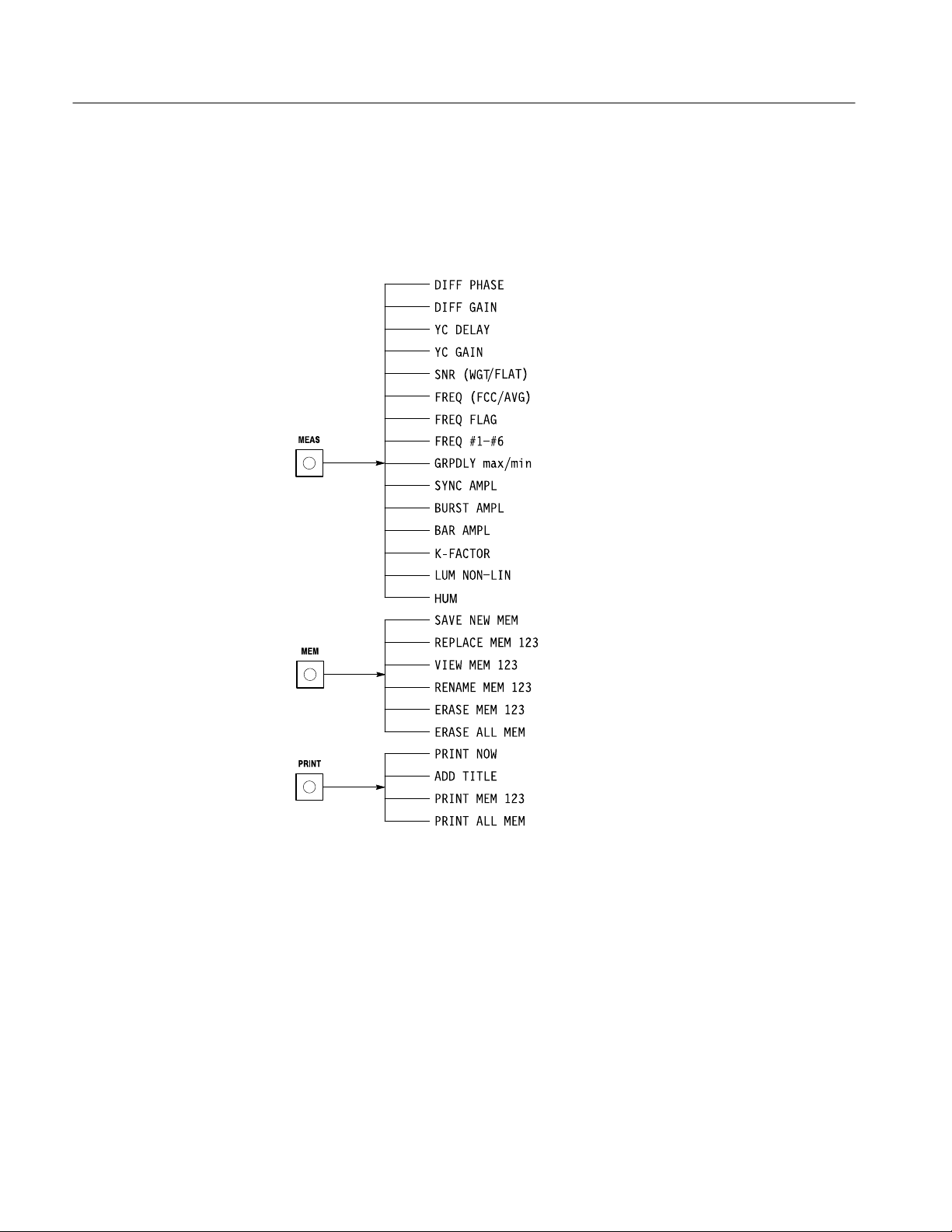
Figure 2–3: The Meas, Mem, and Print menus 2–4. . . . . . . . . . . . . . . . . .
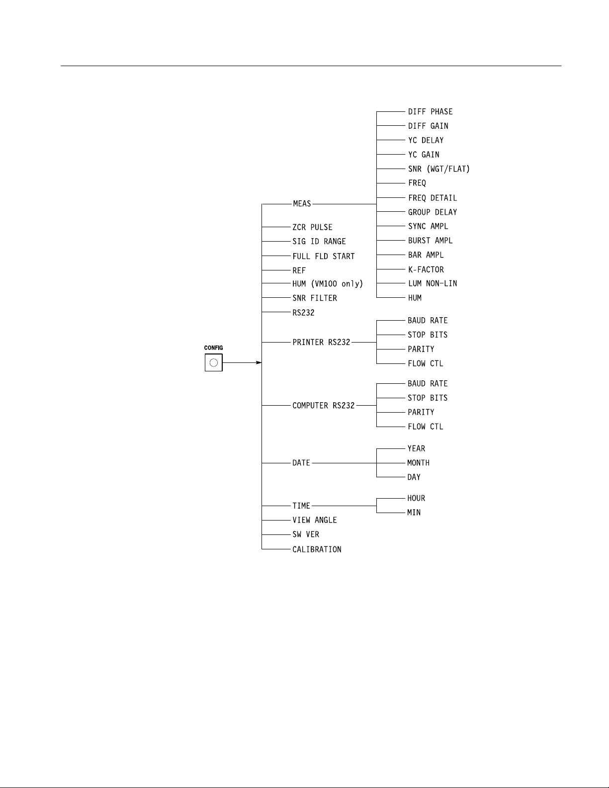
Figure 2–4: The CONFIG menu 2–5. . . . . . . . . . . . . . . . . . . . . . . . . . . . . .
Figure 2–5: Rear panel connectors 2–6. . . . . . . . . . . . . . . . . . . . . . . . . . . .
Figure 3–1: Simplified view of Gain, DC Offset, and Filtering block 3–5
Figure 3–2: Acquisition and DSP system 3–8. . . . . . . . . . . . . . . . . . . . . . .
Figure 3–3: Host processor and memory system 3–10. . . . . . . . . . . . . . . . .
Figure 4–1: Initial setup for the PV procedure 4–4. . . . . . . . . . . . . . . . . . .
Figure 5–1: Equipment setup for the adjustment procedure 5–4. . . . . . .
Figure 6–1: Top cover replacement 6–8. . . . . . . . . . . . . . . . . . . . . . . . . . . .
Figure 6–2: Front panel assembly replacement 6–9. . . . . . . . . . . . . . . . . .
Figure 6–3: Front panel board replacement 6–10. . . . . . . . . . . . . . . . . . . . .
Figure 6–4: Main board removal 6–11. . . . . . . . . . . . . . . . . . . . . . . . . . . . . .
Figure 6–5: Front panel assembly removal 6–12. . . . . . . . . . . . . . . . . . . . . .
Figure 6–6: Power supply board replacement 6–13. . . . . . . . . . . . . . . . . . .
Figure 6–7: LCD board replacement 6–15. . . . . . . . . . . . . . . . . . . . . . . . . . .
Figure 6–8: Lithium battery replacement 6–16. . . . . . . . . . . . . . . . . . . . . . .
Figure 6–9: Power supply test points and limits 6–19. . . . . . . . . . . . . . . . . .
Figure 6–10: Location of diagnostic LEDs 6–21. . . . . . . . . . . . . . . . . . . . . .
Figure 6–11: Setup for measuring analog signals 6–22. . . . . . . . . . . . . . . . .
Figure 6–12: Waveform at A2TP9 6–23. . . . . . . . . . . . . . . . . . . . . . . . . . . . .
Figure 6–13: Waveform at A2TP10 6–23. . . . . . . . . . . . . . . . . . . . . . . . . . . .
Figure 6–14: VIDEO waveform at A2TP31 6–24. . . . . . . . . . . . . . . . . . . . .
Figure 6–15: COMP_SYNC waveform at A2TP15 6–24. . . . . . . . . . . . . . .
Figure 6–16: FIELD waveform at A2TP16 6–25. . . . . . . . . . . . . . . . . . . . . .
Figure 6–17: 8FSC_IN waveform at A2U116 pin 7 6–26. . . . . . . . . . . . . . .
Figure 6–18: HPULSE waveform at A2TP18 6–27. . . . . . . . . . . . . . . . . . . .
Figure 6–19: DSP_RCK waveform at A2U48 pin 1 6–27. . . . . . . . . . . . . . .
Figure 6–20: Example of the ACQ:SHOW command PC display 6–28. .
Figure 6–21: Setup for using the ACQ:SHOW command 6–29. . . . . . . . .
Figure 9–1: Interconnect diagram 9–3. . . . . . . . . . . . . . . . . . . . . . . . . . . . .
iv
VM100 & VM101 Service Manual
Page 9

Table of Contents
Figure 9–2: Block diagram 9–4. . . . . . . . . . . . . . . . . . . . . . . . . . . . . . . . . . .
Figure 9–3: A2 Main board view A (671-3250-00/01/02/03) 9–5. . . . . . . .
Figure 9–4: A2 Main board view B (671-3250-00/01/02/03) 9–6. . . . . . . .
Figure 9–5: A2 Main board view C (671-3250-00/01/02/03) 9–7. . . . . . . .
Figure 9–6: A2 Main board component locator
(671-3250-00/01/02/03) 9–8. . . . . . . . . . . . . . . . . . . . . . . . . . . . . . . . . . .
Figure 9–7: A2 Main board view A (671-3751-00) 9–9. . . . . . . . . . . . . . . .
Figure 9–8: A2 Main board view B (671-3751-00) 9–10. . . . . . . . . . . . . . . .
Figure 9–9: A2 Main board section C (671-3751-00) 9–11. . . . . . . . . . . . . .
Figure 9–10: A2 Main board component locator (671-3751-00) 9–12. . . . .
Figure 9–11: A1 Front Panel board 9–26. . . . . . . . . . . . . . . . . . . . . . . . . . . .
Figure 10–1: Exploded view 10–8. . . . . . . . . . . . . . . . . . . . . . . . . . . . . . . . . .
VM100 & VM101 Service Manual
v
Page 10

Table of Contents
List of Tables
Table 1–1: Input signal requirements–VIDEO INPUT 1–3. . . . . . . . . . .
Table 1–2: Input signal requirements–EXT REF 1–3. . . . . . . . . . . . . . . .
Table 1–3: Measurement accuracy 1–3. . . . . . . . . . . . . . . . . . . . . . . . . . . .
Table 1–4: Output 1–5. . . . . . . . . . . . . . . . . . . . . . . . . . . . . . . . . . . . . . . . .
Table 1–5: AC power source 1–5. . . . . . . . . . . . . . . . . . . . . . . . . . . . . . . . .
Table 1–6: Environmental characteristics 1–5. . . . . . . . . . . . . . . . . . . . . .
Table 1–7: Certifications and compliances 1–6. . . . . . . . . . . . . . . . . . . . . .
Table 1–8: Physical characteristics 1–7. . . . . . . . . . . . . . . . . . . . . . . . . . .
Table 1–9: Remote control port 1–7. . . . . . . . . . . . . . . . . . . . . . . . . . . . . . .
Table 2–1: Configuration parameters 2–7. . . . . . . . . . . . . . . . . . . . . . . . .
Table 2–2: Print parameters 2–12. . . . . . . . . . . . . . . . . . . . . . . . . . . . . . . . .
Table 2–3: Computer interface parameters 2–13. . . . . . . . . . . . . . . . . . . . .
Table 2–4: Date parameters 2–14. . . . . . . . . . . . . . . . . . . . . . . . . . . . . . . . . .
Table 2–5: Time parameters 2–15. . . . . . . . . . . . . . . . . . . . . . . . . . . . . . . . .
Table 3–1: Power-on diagnostics 3–11. . . . . . . . . . . . . . . . . . . . . . . . . . . . . .
Table 4–1: Test Equipment 4–2. . . . . . . . . . . . . . . . . . . . . . . . . . . . . . . . . .
Table 5–1: Adjustments after repair 5–1. . . . . . . . . . . . . . . . . . . . . . . . . . .
Table 5–2: Required test equipment 5–2. . . . . . . . . . . . . . . . . . . . . . . . . . .
Table 5–3: Adjustment steps 5–5. . . . . . . . . . . . . . . . . . . . . . . . . . . . . . . . .
Table 6–1: Relative susceptibility to static discharge damage 6–2. . . . . .
Table 6–2: External inspection check list 6–4. . . . . . . . . . . . . . . . . . . . . . .
Table 6–3: Internal inspection check list 6–4. . . . . . . . . . . . . . . . . . . . . . .
Table 6–4: Tools required for module replacement 6–8. . . . . . . . . . . . . . .
Table 6–5: Power-on diagnostics 6–20. . . . . . . . . . . . . . . . . . . . . . . . . . . . . .
Table 6–6: Control mode communications parameters 6–31. . . . . . . . . . .
Table 7–1: Power cord identification 7–2. . . . . . . . . . . . . . . . . . . . . . . . . .
vi
VM100 & VM101 Service Manual
Page 11

General Safety Summary
Review the following safety precautions to avoid injury and prevent damage to
this product or any products connected to it.
Only qualified personnel should perform service procedures.
If this equipment is used in any manner not specified, including failure to follow
any rating or direction for use, the protection provided by the equipment may be
impaired.
Injury Precautions
Product Damage
Precautions
Use Proper Power Cord. To avoid fire hazard, use only the power cord specified
for this product.
Avoid Overvoltage. To avoid electric shock or fire hazard, do not apply potential
to any terminal, including the common terminal, that varies from ground by
more than the maximum rating for that terminal.
Ground the Product
of the power cord. To avoid electric shock, the grounding conductor must be
connected to earth ground. Before making connections to the input or output
terminals of the product, ensure that the product is properly grounded.
Do Not Operate Without Covers. To avoid electric shock or fire hazard, do not
operate this product with covers or panels removed.
Use Proper Fuse. To avoid fire hazard, use only the fuse type and rating specified
for this product.
Do Not Operate in Wet/Damp Conditions. To avoid electric shock, do not operate
this product in wet or damp conditions.
Do Not Operate in an Explosive Atmosphere. To avoid injury or fire hazard, do not
operate this product in an explosive atmosphere.
Use Proper Power Source. Do not operate this product from a power source that
applies more than the voltage specified.
. This product is grounded through the grounding conductor
Provide Proper Ventilation. To prevent product overheating, provide proper
ventilation.
Do Not Operate With Suspected Failures. If you suspect there is damage to this
product, have it inspected by qualified service personnel.
Symbols and Terms
VM100 & VM101 Service Manual
T erms in this Manual. These terms may appear in this manual:
vii
Page 12
General Safety Summary
WARNING. Warning statements identify conditions or practices that could result
in injury or loss of life.
CAUTION. Caution statements identify conditions or practices that could result in
damage to this product or other property.
T erms on the Product. These terms may appear on the product:
DANGER indicates an injury hazard immediately accessible as you read the
marking.
WARNING indicates an injury hazard not immediately accessible as you read the
marking.
CAUTION indicates a hazard to property including the product.
Symbols on the Product. The following symbols may appear on the product:
Certifications and
Compliances
DANGER
High Voltage
Protective Ground
(Earth) T erminal
ATTENTION
Refer to Manual
Double
Insulated
Refer to the specifications section for a listing of certifications and compliances
that apply to this product.
viii
VM100 & VM101 Service Manual
Page 13

Service Safety Summary
Only qualified personnel should perform service procedures. Read this Service
Safety Summary and the General Safety Summary before performing any service
procedures.
Do Not Service Alone. Do not perform internal service or adjustments of this
product unless another person capable of rendering first aid and resuscitation is
present.
Disconnect Power. To avoid electric shock, disconnect the main power by means
of the power cord or, if provided, the power switch.
Use Care When Servicing With Power On. Dangerous voltages or currents may
exist in this product. Disconnect power, remove battery (if applicable), and
disconnect test leads before removing protective panels, soldering, or replacing
components.
To avoid electric shock, do not touch exposed connections.
VM100 & VM101 Service Manual
ix
Page 14

Service Safety Summary
x
VM100 & VM101 Service Manual
Page 15

Preface
Use this manual to service the video measurement set to the module or component level. Contact your local Tektronix service center or sales engineer for more
information on repair and adjustment services.
Related Manuals
The VM100 & VM101 Video Measurement Sets User Manual (Tektronix part
number 070-9522-XX) describes how to use the video measurement set.
Service Manual Conventions
In this manual, the term “module” refers to any field-replaceable component,
assembly, or part of the video measurement set.
Strategy for Servicing
To prevent personal injury or instrument damage:
H This product should be serviced only by a qualified service person
H Read the General and Service Safety Summaries at the front of this manual,
as well as Operating Information beginning on page 2–1
H Follow all warnings, cautions, and notes in this manual
Adjustment Interval
Generally, you should perform the Adjustment Procedures once a year. In
addition, perform the procedures after module replacement.
Tektronix Service Offerings
Tektronix provides service to cover repair under warranty as well as other
services that may provide a cost-effective answer to your service needs.
Whether providing warranty repair service or any of the other services listed
below, Tektronix service technicians are well equipped to service the video
measurement set. Tektronix technicians train on Tektronix products and have
access to the latest information on product improvements and new options.
VM100 & VM101 Service Manual
xi
Page 16

Preface
Warranty Repair Service
At-Depot Repair or
Calibration Service
Module Exchange
Contacting Tektronix
Tektronix warrants this product for one year from date of purchase. The warranty
appears behind the title page in this manual. Tektronix technicians provide
warranty service at most Tektronix service locations worldwide. The Tektronix
product catalog lists all service locations worldwide.
The following services can be purchased to meet to your repair/calibration needs.
H A single repair and/or adjustment
H Calibrations using equipment and procedures that meet the traceability
standards specific to the local area
H Annual maintenance agreements that provide for either calibration and
repair, or calibration only.
Reduce down time for repair by exchanging modules for remanufactured ones.
Tektronix ships an updated and tested exchange module from the Beaverton,
Oregon service center, typically within 24 hours. Each module comes with a
90-day service warranty.
Product
Support
Service
Support
For other
information
To write us Tektronix, Inc.
For application-oriented questions about a Tektronix measurement product, call toll free in North America:
1-800-TEK-WIDE (1-800-835-9433 ext. 2400)
6:00 a.m. – 5:00 p.m. Pacific time
Or contact us by e-mail:
tm_app_supp@tek.com
For product support outside of North America, contact your
local Tektronix distributor or sales office.
Contact your local Tektronix distributor or sales office. Or visit
our web site for a listing of worldwide service locations.
http://www.tek.com
In North America:
1-800-TEK-WIDE (1-800-835-9433)
An operator will direct your call.
P.O. Box 1000
Wilsonville, OR 97070-1000
xii
VM100 & VM101 Service Manual
Page 17

Specifications
Product Description
This chapter provides a complete description of the specifications. Product
Description is a general description of the instrument. The Specification Tables,
which begin on page 1–2, contain the complete specifications.
The Tektronix VM100 and VM101 Video Measurement Sets are automatic video
measurement instruments. The VM100 measures NTSC signals and the VM101
measures PAL signals.
The video measurement sets use existing or inserted test signals and take
measurements consistent with regulatory specifications.
The video measurement sets display measurement results on a LCD screen. You
can also display measurement results on a serial printer or remote PC using the
RS-232 port. The video measurement sets perform the following measurements
(on-screen labels are shown in parentheses):
Differential Phase (DIFF PHASE)
Differential Gain (DIFF GAIN)
Chrominance-to-Luminance Delay (YC DELAY)
Chrominance-to-Luminance Gain (YC GAIN)
Signal-to-Noise Ratio (SNR WGT/FLAT)
Frequency Response (FREQ FCC or AVG)
Frequency Response Detail (FREQ FLAG, FREQ #1 through FREQ #6) or
(FRQmax and FRQmin)
Group Delay (GRPDLYmax and GRPDLYmin)
Sync Amplitude (SYNC AMPL)
Burst Amplitude (BURST AMPL)
Bar Amplitude (BAR AMPL)
2T K-Factor (2T K-FACTOR)
Luminance Nonlinearity (LUM NON-LIN)
Hum (HUM P-P, 50/60 Hz, and 100/120 Hz)
VM100 & VM101 Service Manual
1–1
Page 18

Specifications
Specification Tables
This section provides a complete description of the video measurement set
specifications. Refer to the Performance Conditions for a description of the
required temperature range and other pertinent operating conditions.
Terms Used in
Specifications
Performance Conditions
Characteristic. A characteristic refers to a property of the product.
Performance Requirement [REQ]. Performance Requirements define
characteristics that are essential to the intended application of the product,
usually in limit form.
Reference Information [RI]. Reference Information explains the performance
requirements or stipulates conditions under which the performance requirements
are effective. Reference information is not considered to be a statement of
guaranteed performance.
Specification. A specification is a document or a section of a document that lists
and describes characteristics and performance requirements of a product.
Typical. Typical refers to instrument performance that can be expected but is not
guaranteed.
The performance requirements listed in the Electrical Specifications apply over
an ambient temperature range of 0° C to +50° C. The rated accuracies are valid
over the entire 0° C to 50° C range and become “typical” for temperatures from
–10° C to 0° C. Test equipment used to verify performance requirements must be
calibrated and working within the specified limits.
All specifications (with the exception of Signal-to-Noise Ratio Measurement
Accuracy) apply for Signal-To-Noise Ratio ≥ 52 dB (weighted). Averaging
(AVG) is enabled for all specifications.
1–2
VM100 & VM101 Service Manual
Page 19

Electrical Specifications
T able 1–1: Input signal requirements–VIDEO INPUT
Category Description
Maximum Operating Voltage REQ: –1.8 V to +2.2 V
Absolute Maximum Input Voltage REQ: –8.5 V to +8.5 V
Minimum Operating Voltage REQ: 1 Vp-p video signal
RI: Typically operates with a 1 Vp-p input, +1 dB or –6 dB
DC Input Impedance REQ: ≥20 KW
RI: DC coupling
Return Loss REQ: >40 dB to 6 MHz
RI: DC coupling
Specifications
T able 1–2: Input signal requirements–EXT REF
Category Description
Absolute Maximum Input Voltage REQ: –8.5 V to +8.5 V
Minimum Operating Voltage REQ: 1 Vp-p video signal
RI: Typically operates with a 1 Vp-p input, +1 dB or –6 dB
DC Input Impedance REQ: ≥20 KW
Return Loss REQ: >40 dB to 6 MHz
Video INPUT / EXT REF
Loop-through Isolation RI: >70 dB (typical)
Crosstalk REQ: >70 dB to 6 MHz
T able 1–3: Measurement accuracy
Category
Differential Phase REQ: <1.0 °
Differential Gain REQ: <2.0 %
1
Description
RI: Typically <0.5° from 20° C to 30° C with test signal generator source
RI: Typically <1 % from 20° C to 30° C for nominal 300 mV chrominance
amplitude
1
All tests are performed with AVG enabled. Processing time for each measurement is a function of the signal-to-noise
ratio.
VM100 & VM101 Service Manual
1–3
Page 20

Specifications
T able 1–3: Measurement accuracy (cont.)
Category
1
Description
Chrominance-to-Luminance Gain REQ: <2 %
RI: Typically <1 % from 20° C to 30° C with test signal generator source
Chrominance-to-Luminance Delay REQ: <20 ns
REQ: <10 ns from 20° C to 30° C with test signal generator source.
RI: Typically <5 ns from 20° C to 30° C with test signal generator source
Frequency Response REQ: <0.2 dB
RI: Typically <0.1 dB (1 %) from 20° C to 30° C with test signal generator
source
RI: VM100: 50 kHz to 4.2 MHz
VM101: 50 kHz to 5.8 MHz
2T K-Factor REQ: 2 %
RI: Typically <0.5 % from 20° C to 30° C with test signal generator source
2
Hum
REQ: ±1.0% for hum ≤4.0%
±2.0% for hum >4.0% and <15.0%
RI: Typically ±0.5% for hum ≤4.0%
Signal-to-Noise Ratio
(Weighted or Flat)
REQ: ±1 dB, 28 dB to <45 dB
±2 dB, 45 dB to <60 dB
±3 dB, 60 dB to 67 dB (WGT)
RI: VM100: Noise is weighted with EIA RS-250-B 5 MHz weighted noise
filter (T ektronix part number 015-0215-00 equivalent)
VM101: Noise is weighted with CCIR 567 weighted noise filter
Group Delay REQ: <20 ns
RI: 50 kHz to 4.8 MHz, within the bandwidth of the signal under test
Sync Amplitude
2
REQ: <1.0%
Burst Amplitude REQ: <1.0%
Bar Amplitude REQ: <1.0%
Luminance Nonlinearity REQ: <1.0%
1
All tests are performed with AVG enabled. Processing time for each measurement is a function of the signal-to-noise ratio.
2
The hum and sync amplitude measurements are inaccurate in the presence of Sound In Sync (SIS) signals.
1–4
VM100 & VM101 Service Manual
Page 21

Specifications
T able 1–4: Output
Category Description
Zero Carrier Reference Pulse Output RI: Can drive demodulator ZCRP trigger of TTL type (Tektronix TDM5,
DS1200, 1450) or 1.5 V
, 75 W type (Tektronix 1340, 1350)
p-p
T able 1–5: AC power source
Category Description
Mains Voltage Range REQ: 90-250 VAC
50/60 Hz
0.7 A
Power Consumption REQ: 30 W maximum
Environmental Characteristics
T able 1–6: Environmental characteristics
Category
Altitude
(see page 1–6 for safety-related information)
Humidity REQ: To 95% relative humidity at or below +50° C
Operating Temperature REQ: 0° C to + 50° C (32° F to 122° F)
Package Drop REQ: Meets Tektronix 062-2858-00, Rev. B
Random Vibration
(Operating and Non-Operating)
Shock (Operating) REQ: Meets Tektronix Class III (062-2858-00, Rev. B)
Storage Temperature REQ: –40° C to + 75° C (–40° F to +167° F)
Loose Load Vibration
(Repetitive Shock)
Vehicle Vibration REQ: Meets Tektronix 062-2858-00, Rev. B
Description
REQ: Operating: to 15,000 f (4572 m)
Non-operating: to 50,000 f (15,240 m)
RI: Maximum operating temperature decreases 1° C per 1000 f (305 m)
RI: Electrical specifications are guaranteed when the instrument is
operated in this temperature range
REQ: Meets Tektronix Class III (062-2858-00, Rev. B)
RI: Three drops on each face of 50 g, 11 ms duration, half-sine pulse
shape for a total of 18 drops
REQ: Meets Tektronix 062-2858-00, Rev. B (page 51, section 17.7.4)
VM100 & VM101 Service Manual
1–5
Page 22

Specifications
ertifications
Safety Standards and Certification
T able 1–7: Certifications and compliances
Category Description
Altitude
(Maximum Operating)
See page 1–5 for additional information
C
US Nationally Recognized Testing
Laboratory Listing
Canadian
Certification
European Union Compliance Low Voltage Directive 73/23/EEC, Amended by 93/68/EEC
Additional
Compliance
EC Declaration of
Conformity
Operating: to 6,500 f (2000 m)
ANSI/ISA S82
Safety Standard for Electrical and Electronic Test, Measuring, Controlling, and
Related Equipment
CAN/CSA C22.2 No.1010.1
Safety Requirements for Electrical Equipment for Measurement, Control, and
Laboratory Use
UL31 11-1
Standard for Electrical Measuring and Test Equipment
IEC 1010-1
Safety Requirements for Electrical Equipment for Measurement, Control, and
Laboratory Use
Meets intent of Directive 89/336/EEC for Electromagnetic Compatibility and Low
Voltage Directive 73/23/ECC for Product Safety. Compliance was demonstrated to
the following specifications as listed in the Official Journal of the European
Communities:
EMC Directive 89/336/EEC:
EN 50081-1 Emissions:
EN 55022 Class B Radiated and Conducted
Emissions
EN 50082-1 Immunity:
IEC 801-2 Electrostatic Discharge Immunity
IEC 801-3 RF Electromagnetic Field Immunity
IEC 801-4 Electrical Fast T ransient/Burst
Immunity
3
Low Voltage Directive 73/23/EEC:
EN 61010-1 Safety requirements for electrical
equipment for measurement, control,
and laboratory use
3
Using high quality shielded cables.
Equipment Type Test and Measuring
FCC Compliance Emissions comply with FCC Code of Federal Regulations 47, Part 15, Subpart B,
Class A Limits
1–6
VM100 & VM101 Service Manual
Page 23
T able 1–7: Certifications and compliances (cont.)
erial Port
Category Description
Overvoltage Category Overvoltage Category II (as defined in IEC 1010-1, Annex J)
Pollution Degree Pollution Degree 2 (as defined in IEC 1010-1); rated for indoor use only
Safety Class Class I (as defined in IEC 1010-1, Annex H)
T emperature (Operating) +5° C to +50° C (+41° F to 122° F)
Physical Characteristics
T able 1–8: Physical characteristics
Category Description
Dimensions Height: 1.71 in (4.34 cm) Nominal
Width: 8.1 in (20.6 cm) Nominal
Depth: 17.2 in (43.7 cm) Nominal
Stand-Alone Instrument Weight 4.00 lbs (1.81 kg) Nominal
Packaged Weight (for domestic shipment) 7.12 lbs (3.23 kg) Nominal
Specifications
Remote Control Port
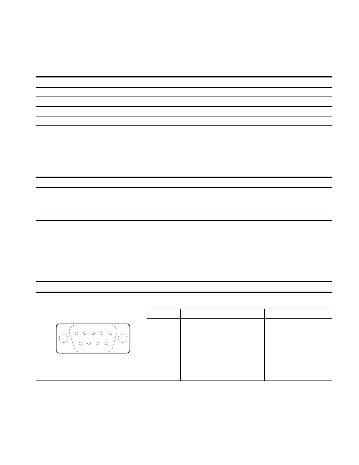
T able 1–9: Remote control port
Category Description
RS232 S
12345
6789
Connector: Nine-pin DCE female
Baud Rate: 1200, 2400, 9600, or 19.2K
Pin Signal Name RS232-C Name
1
2
3
4
5
6
7
8
9
Not Used
TX (Transmit Data; Output)
RX (Receive Data; Input)
Not Used
GND (Signal Ground)
Not Used
RTS (Request to Send; Output)
CTS (Clear to Send; Input)
Not Used
BA
BB
AB
CA
CB
VM100 & VM101 Service Manual
1–7
Page 24

Specifications
1–8
VM100 & VM101 Service Manual
Page 25

Operating Information
This section describes how to operate the video measurement set. The operating
information is limited to the functions required to perform the procedures found
in this manual. More detailed operating instructions can be found in the VM100
& VM101 Video Measurement Sets User Manual (Tektronix part number
070-9522-XX).
The Operating Information is divided into the following sections:
H Installation describes the power source requirements and explains where to
find a list of the power cord options
H Operating Information on page 2–1 describes the front panel buttons and
LCD display, the menus, the rear panel connectors, the power on procedure,
and configuration instructions
Installation
Power Source
Requirements
Operating Information
The video measurement set operates over the range of 90 V
either 50 Hz or 60 Hz. The power source should never apply more than 250 V
between the supply conductors or between either supply conductor and ground.
WARNING. To avoid personal injury due to electrical shock, never operate the
video measurement set without the protective ground connection by way of the
grounding conductor in the power cord.
This section provides the information you will need to operate the video
measurement set when performing the procedures in this manual. It contains the
following information:
H Descriptions of the front panel buttons and the LCD display
H Descriptions of the menus
H Descriptions of the rear panel connectors
H Power on procedure
to 250 V
rms
rms
at
rms
H Configuration instructions for each operating mode
VM100 & VM101 Service Manual
2–1
Page 26
Operating Information
Front Panel Buttons and
LCD Display
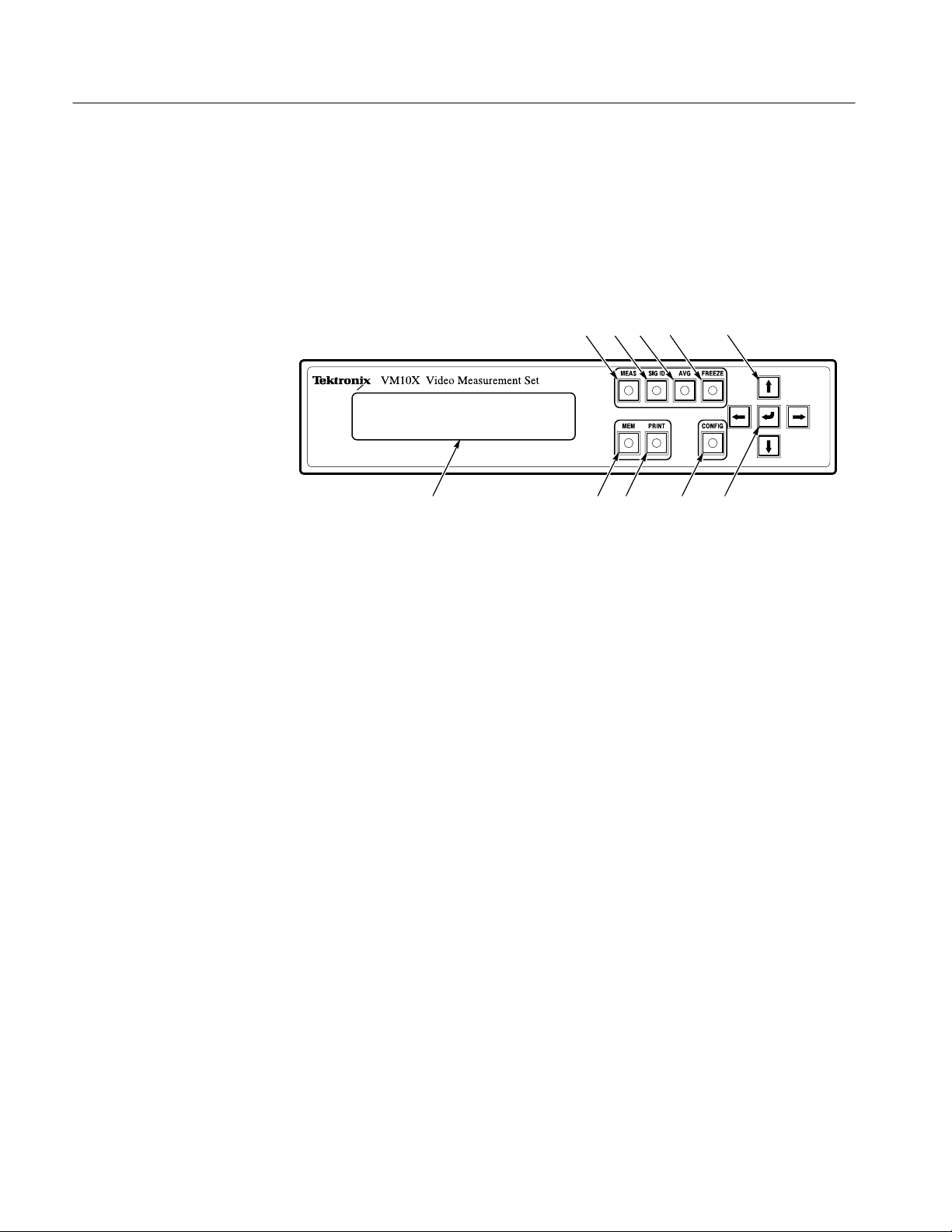
The front panel contains twelve buttons and an LCD display as shown in
Figure 2–1. There are seven function buttons, four arrow buttons, and the enter
button. A green LED indicator, located at the center of each function button,
lights to show when the associated function is turned on. The arrow buttons are
designated by directional arrows. A carriage return symbol (↵) identifies the
enter button.
1 2 4
10
3
9 8 7 6
5
Figure 2–1: Front panel
Five of the function buttons (MEAS, SIG ID, MEM, PRINT, and CONFIG) are
exclusive to each other. This means that only one of the functions can be active
at a time. When you press another of these buttons, the previous function
automatically turns off.
The following descriptions refer to Figure 2–1.
MEAS. Press the measure button to display the results of measurements the
1
video measurement set makes on the LCD display. Use the CONFIG menu to
turn measurements ON or OFF. Measurements must be ON to appear in the
MEAS list.
2
SIG ID. Press the signal identification button to display the name and location
of signals in the vertical interval and the source ID (when contained in the
signal).
3
AVG. Press this toggle switch to turn signal averaging on and off.
FREEZE. Press this toggle switch to turn the freeze feature on and off. When
4
FREEZE is turned on, all acquisition and measurement activity stops so that
you can view intermediate measurement and signal ID results.
5
Arrow Buttons. Press the up (↑) or down (↓) arrow buttons to scroll through
various LCD displays. Press the left (←) and right (→) arrow buttons to
change instrument parameters and to view measurement results on other
video lines.
2–2
VM100 & VM101 Service Manual
Page 27
Operating Information
6
Enter Button. Press the enter (↵) button to enter and exit the CONFIG
submenus and to control print and memory functions.
CONFIG. Press the configure button to access instrument configuration menus
7
and to view the instrument software version.
PRINT. Press the print button to print the current or saved measurement data or
8
to output results to a computer, using the RS-232 serial port. You must
configure the RS-232 port for printing and select the print parameters before
using the print function.
9
MEM. Press the memory button to save the current measurement and SIG ID
results in instrument memory and to access memory management selections
including ERASE, REPLACE, VIEW, and RENAME.
10
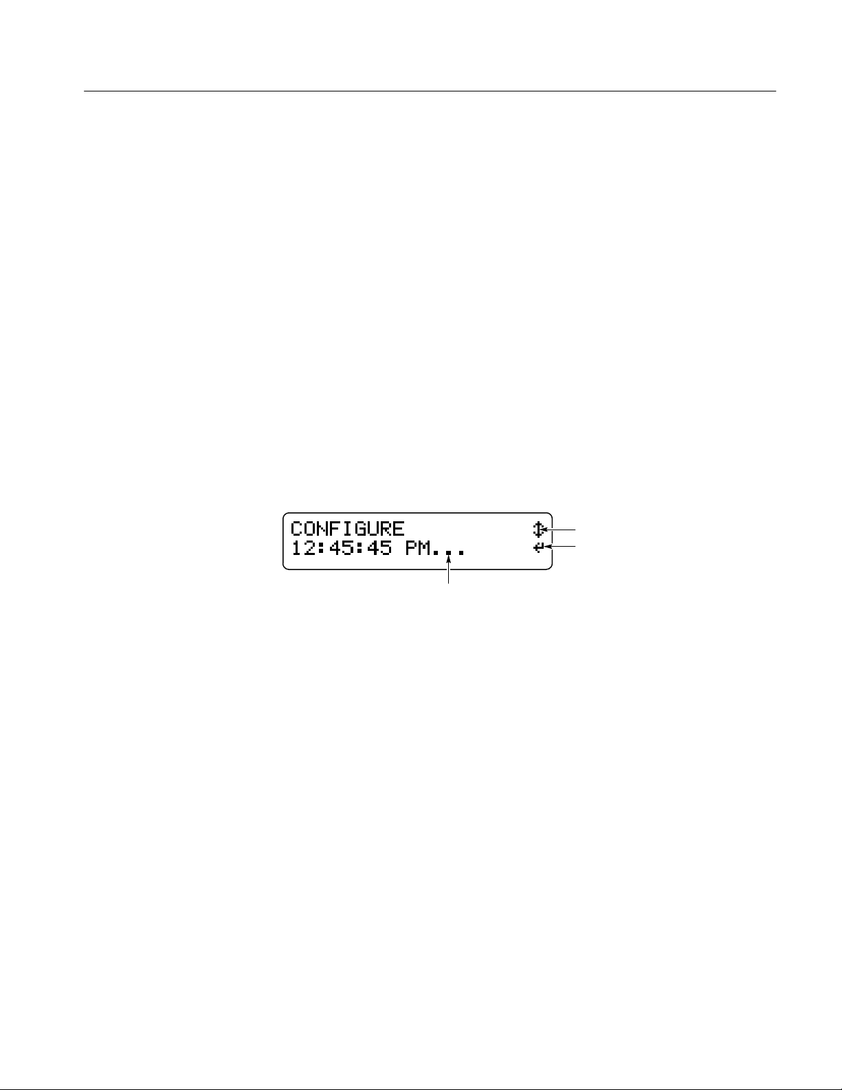
LCD Display . The LCD display shows measurement readouts and menu
selections. Figure 2–2 shows examples of the text and symbols you will see
on the LCD display. The symbols help you navigate quickly through the
menu system using the arrow buttons and the enter button. Dots (…)
following the menu name indicate that a menu has a submenu.
Shows submenu
Figure 2–2: LCD display characteristics
Arrow buttons
Enter button
VM100 & VM101 Service Manual
2–3
Page 28
Operating Information
Menus
The MEAS, SIG ID, MEM, PRINT, and CONFIG buttons allow access to
additional selections or measurement results. Figures 2–3 and 2–4 show the
menu structure of the video measurement set. The SIG ID menu is not shown
because its contents depend upon the input signal characteristics.
2–4
Figure 2–3: The MEAS, MEM, and PRINT menus
VM100 & VM101 Service Manual
Page 29
Operating Information
Figure 2–4: The CONFIG menu
VM100 & VM101 Service Manual
2–5
Page 30
Operating Information
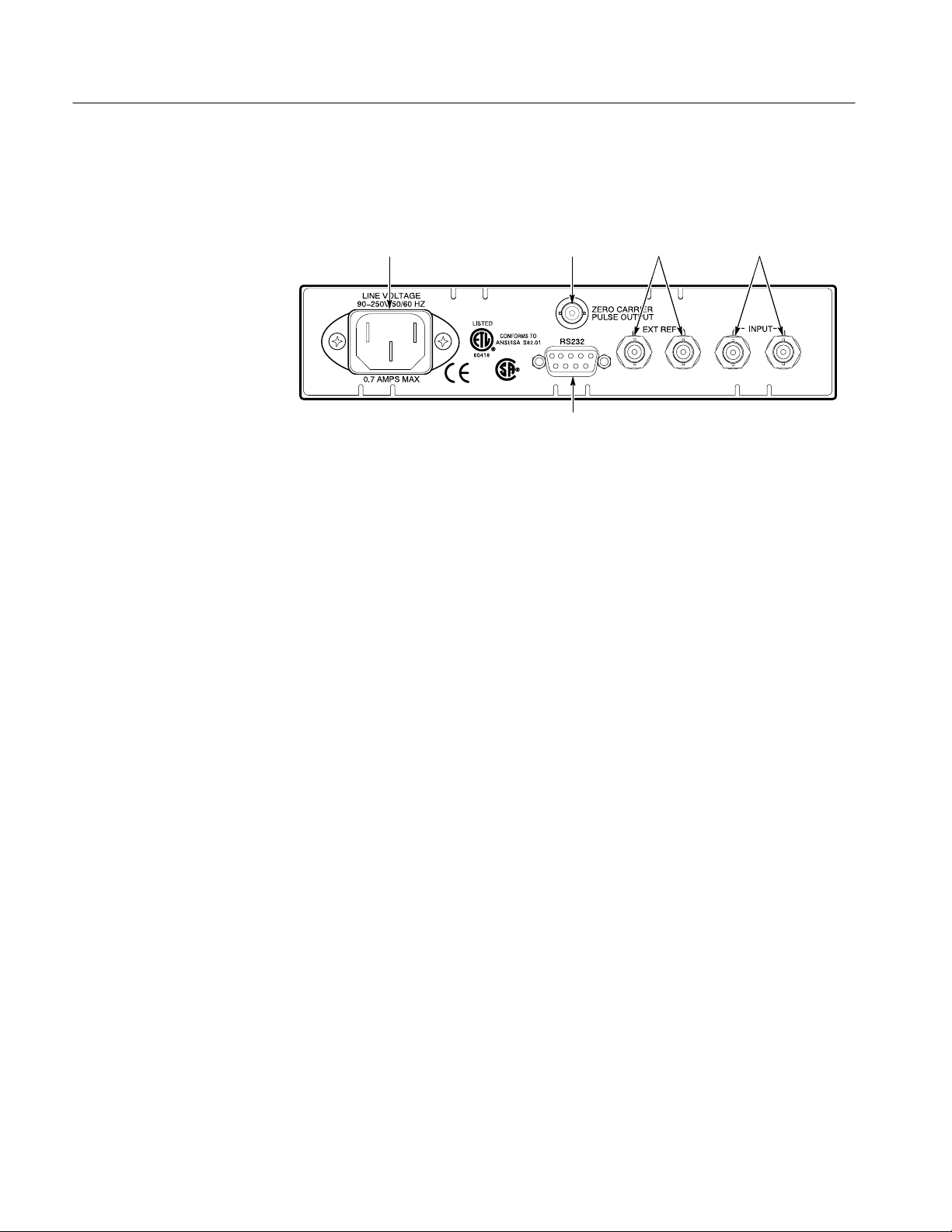
Rear Panel Connectors
There are seven connectors mounted on the video measurement set rear panel.
Refer to Figure 2–5 for descriptions.
1
2
3 4
5
Figure 2–5: Rear panel connectors
AC Power Connector. The AC power connector is a standard AC plug receptacle
1
for 120 or 240 V
power mains. The plug is compatible with each available
ac
power cord option.
2
ZERO CARRIER PULSE OUTPUT. The ZERO CARRIER PULSE OUTPUT
produces a reference pulse that triggers a demodulator. Signal amplitude is
1.5 V
when driving a 75 W load or TTL compatible when driving a high
p-p
impedance. This pulse is compatible with the trigger inputs on the following
Tektronix Demodulators: DS1200, TDM5, 1450, 1340, and 1350.
EXT REF. This high-impedance, loop-through input (two BNC connectors)
3
accepts external reference signals of composite video or black burst (1 V
Use this input if the video input has no sync information. The input is AC
coupled and compensated for 75 W. It is not internally terminated.
4
INPUT. This high-impedance, loop-through input (two BNC connectors)
accepts video input signals for the video measurement set. The input is AC
coupled and compensated for 75 W. It is not internally terminated.
5
RS232 Port. This nine-pin subminiature D-type female connector provides an
RS232 serial interface for printer and computer communication. The port also
provides the interface for waveform the monitor control function.
p-p
).
2–6
VM100 & VM101 Service Manual
Page 31

Operating Information
Power On Procedure
Configuration
To power on the video measurement set, connect it to the AC power source.
There is no power switch.
The power-on sequence completes in approximately 10 seconds. After power on
completes, check for the following conditions:
The LCD display shows the message No video present, or no lock possible
(if no signals are connected to the rear panel INPUT connector).
The MEAS button indicator lights.
NOTE. The AVG button indicator lights at power on if the AVG feature was in
use when AC power was last disconnected.
This section guides you through the configuration of each operating parameter.
(No configuration is necessary for basic operation.) Refer to Table 2–1 for an
overview of the parameters you can configure, the location of the configuration
instructions, and the factory default values.
If you need more detailed information about the instrument features, refer to the
VM100 & VM101 Video Measurement Sets User Manual (Tektronix part number
070-9522-XX).
NOTE. You cannot configure the hum frequency on the VM101.
The default value is 50 Hz.
T able 2–1: Configuration parameters
Parameter Page Number Factory Default Value
MEASURE 2–8 SNR is ON
All other measurements are OFF
ZCR PULSE 2–9 VM100: Line 10
VM101: Line 7
SIG ID RANGE 2–10 VITS
FULL FLD START 2–10 23
REF 2–11 Input
HUM (VM100 only) 2–11 60HZ
SNR FILTER 2–1 1 WEIGHTD
RS232 2–1 1 for printing
2–12 for computer
2–13 for waveform monitor operation
Computer
VM100 & VM101 Service Manual
2–7
Page 32

Operating Information
T able 2–1: Configuration parameters (cont.)
Parameter Factory Default V aluePage Number
PRINTER RS232
BAUD RATE
STOP BITS
PARITY
FLOW CTL
COMPUTER
RS232
BAUD RATE
STOP BITS
PARITY
FLOW CTL
1995 NOV 11 (Date)
YEAR
MONTH
DA Y
10:13:18AM (Time)
HOUR
MINUTE
VIEW ANGLE 2–15 80
SW VER 2–15 Current software version
CALIBRA TE 2–15 N/A
2–1 1
9600
1
NONE
NONE
2–12
9600
1
NONE
NONE
2–14 Today’s date
2–14 Current time
Use the following procedures to customize the operation of the video measurement set. Once you have configured the parameters, the video measurement set
powers on as you configured it. Refer to page 2–1 for detailed descriptions of
the front panel buttons or the LCD display.
NOTE. The video measurement set
uses the last setting that was saved for each
parameter if power is interrupted during configuration.
To exit the CONFIGURE menu at any time during these procedures, press the
MEAS, SIG ID, MEM, or PRINT buttons.
Configure the Measurements. The video measurement set
performs a group of
measurements when you press the MEAS button. The display update rate
depends upon the number of measurements made and the presence of valid input
signals. You can customize this feature for your application by selecting only the
measurements you need.
2–8
VM100 & VM101 Service Manual
Page 33

Operating Information
Perform the following steps to choose measurements that will be performed
when you press the MEAS button:
1. 2. 3. 4. 5.
Press the CONFIG
button.
Select
CONFIGURE
MEASURE
(default). Press the
↵ enter button.
Select the desired
measurement. See
list below.
Select ON or OFF.
Repeat steps 3 and
4 to configure
additional
measurements.
The following measurements are available:
Differential Phase (DIFF PHASE)
Differential Gain (DIFF GAIN)
Chrominance-Luminance Delay (YC DELAY)
Chrominance-Luminance Gain (YC GAIN)
Signal-to-Noise Ratio (SNR WGT/FLAT)
Frequency Response (FREQ FCC or AVG and FREQ DETAIL)
Group Delay (GRPDLYmax and GRPDLYmin)
Sync Amplitude (SYNC AMPL)
Burst Amplitude (BURST AMPL)
Press the MEAS
button to exit.
Configure the Zero Carrier Reference Pulse Trigger Output. The Zero Carrier
Reference Pulse Trigger Output synchronizes a demodulator when you take hum
measurements. You can configure the output to OFF or to any line from 10 – 20
(VM100) or 7 – 20 (VM101).
VM100 & VM101 Service Manual
Bar Amplitude (BAR AMPL)
2T K-Factor (2T K-FACTOR)
Luminance Nonlinearity (LUM NON-LIN)
Hum (HUM)
2–9
Page 34

Operating Information
Perform the following steps to configure the Zero Carrier Reference Pulse
Trigger Output:
1. 2. 3. 4.
Press the CONFIG
button.
Select CONFIGURE
ZCR PULSE.
Select OFF or a line
number.
Press the MEAS button
to exit.
Configure the Signal Identification Range. The SIG ID menu displays all of the
test signals that are present in the video signal applied to the INPUT connector.
You can configure the SIG ID range to match your system requirements (VITS
or FULL).
Perform the following steps to configure the SIG ID range:
1. 2. 3. 4.
Press the CONFIG
button.
Select SIG ID RANGE. Select VITS or FULL. Press the MEAS button
to exit.
NOTE. After you configure the signal identification range, the video measurement
set reacquires the signal.
2–10
Configure the Full Field Start Line. You can configure the video line used for full
field start (valid only when the SIG ID range is FULL). With this feature you can
view a specific video line within the active area.
Perform the following steps to configure the Full Field Start Line:
1. 2. 3.
Press the CONFIG
button.
Select FULL FLD
START.
Select 23 - 43 (VM100)
or 23 – 39 (VM101).
4.
Press the MEAS button
to exit.
NOTE. After you configure the full field start line, the video measurement set
reacquires the signal if FULL is selected.
VM100 & VM101 Service Manual
Page 35

Operating Information
Configure the Reference. You can configure the video measurement set to use
either an internally generated sync reference or a signal connected to the
EXT REF rear panel input. For example, use an external reference if the video
input has no sync information.
Perform the following steps to configure the Reference:
1. 2. 3.
Press the CONFIG
button.
Select CONFIGURE
REF.
Select INPUT or
EXTERNAL.
4.
Press the MEAS button
to exit.
Configure the Hum Measurement (VM100 Only). You can configure the hum
measurement to match your power line frequency (VM100 only). The video
measurement set configuration must match your power line frequency to produce
accurate hum measurement results.
Perform the following steps to configure the hum measurement:
1. 2. 3. 4.
Press the CONFIG
button.
Select HUM. Select 50HZ or 60HZ. Press the MEAS button
to exit.
Configure the Signal-to-Noise Ratio Filter. The video measurement set provides
weighted and flat filter selections for taking signal-to-noise measurements. You
can configure the filter type needed for your application.
Perform the following steps to configure the SNR filter:
Configure for Printing. The video measurement set can drive a printer, computer,
or waveform monitor using the RS232 serial port. To print the measurement
results, you must configure the RS232 serial port for printer operation and select
the parameters that match your printer.
VM100 & VM101 Service Manual
1. 2. 3. 4.
Press the CONFIG
button.
Select SNR FILTER. Select WEIGHTD or
FLAT.
Press the MEAS button
to exit.
2–11
Page 36

Operating Information
Perform the following steps to configure the RS232 serial port to drive a printer:
1. 2. 3. 4.
Press the CONFIG
button.
Select CONFIGURE
RS232=.
Select PRINTER. Press the MEAS button
to exit.
NOTE. If the serial port is not configured for printing, the print function is
disabled.
Refer to your printer manual to determine the settings for baud rate, stop bits,
parity, and flow control.
Perform the following steps to configure the print parameters:
1. 2. 3. 4. 5.
Press the CONFIG
button.
Select
CONFIGURE
PRINTER RS232.
Press the ↵ enter
button.
Choose the
appropriate setting
for the displayed
parameter. See
Table 2–2.
Select the next
parameter. See
Table 2–2. Repeat
steps 3 and 4 for all
parameters.
Press the MEAS
button to exit.
T able 2–2: Print parameters
2–12
Parameter Settings
BAUD RA TE 1200, 2400, 9600, 19.2K
STOP BITS 1 or 2
PARITY NONE, EVEN, ODD
FLOW CTL NONE, XON/XOFF, HARDWARE
Configure for Computer Communications. The video measurement set can drive a
computer, printer, or waveform monitor using the RS232 serial port. To send the
measurement results to a computer or to set up for remote operation, you must
configure the RS232 serial port for computer operation and select the parameters
that match your computer interface.
VM100 & VM101 Service Manual
Page 37

Operating Information
Perform the following steps to configure the RS232 port to drive a computer:
1. 2. 3.
Press the CONFIG
button.
Select CONFIGURE
RS232=.
Select COMPUTER. Press the MEAS button
4.
to exit.
NOTE. Refer to your computer manual to determine the settings for baud rate,
stop bits, parity, and flow control.
Perform the following steps to configure the computer interface parameters:
1. 2. 3. 4.
Press the CONFIG
button.
Select
CONFIGURE
COMPUTER
RS232. Press the ↵
enter button.
Choose the
appropriate setting
for the displayed
parameter. See
Table 2–3.
Select the next
parameter. See
Table 2–3. Repeat
steps 3 and 4 for all
parameters.
5.
Press the MEAS
button to exit.
NOTE. If COMPUTER was not selected at power on, you will experience a short
delay when scrolling through the CONFIGURE RS232 menu choices.
T able 2–3: Computer interface parameters
Configure for Waveform Monitor Control Function. The video measurement set can
drive a computer, printer, or 1740A-series waveform monitor using the RS232
serial port. The waveform monitor control function allows you to view the
waveform on a 1740A-series waveform monitor while the video measurement
set measures the signal parameters.
VM100 & VM101 Service Manual
Parameter Settings
BAUD RA TE 1200, 2400, 9600, 19.2K
STOP BITS 1 or 2
PARITY NONE, EVEN, ODD
FLOW CTL NONE, XON/XOFF, HARDWARE
2–13
Page 38

Operating Information
Perform the following steps to configure the RS232 port to drive a waveform
monitor:
1. 2. 3. 4.
Press the CONFIG
button.
Select CONFIGURE
RS232=.
Select CONTROL. Press the MEAS button
to exit.
Configure the Date. The video measurement set keeps track of the date. Perform
the following steps to change the date setting:
1. 2. 3. 4. 5.
Press the CONFIG
button.
Select
CONFIGURE
<DATE>. Press the
↵ enter button.
Choose the
appropriate setting
for the displayed
parameter. See
Table 2–4.
Select the next
parameter. See
Table 2–4. Repeat
steps 3 and 4 for all
parameters.
Press the MEAS
button to exit.
T able 2–4: Date parameters
Parameter Settings
YEAR 1990 through 2089
MONTH JAN through DEC
DA Y 1 through 31
2–14
Configure the Time. The video measurement set keeps track of the time. Perform
the following steps to change the time setting:
1. 2. 3. 4. 5.
Press the CONFIG
button.
Select
CONFIGURE
<TIME>. Press the
↵ enter button.
Choose the
appropriate setting
for the displayed
parameter. See
Table 2–5.
Select the next
parameter. See
Table 2–5. Repeat
steps 3 and 4 for all
parameters.
Press the MEAS
button to exit.
VM100 & VM101 Service Manual
Page 39

Operating Information
T able 2–5: Time parameters
Parameter Settings
HOUR 01AM to 12AM and 01PM to 12PM
MINUTE 00 to 59
Adjust the LCD View Angle. You can adjust the viewing angle of the LCD display
for the best readout with your lighting conditions. To change the viewing angle,
place the video measurement set in the lighting conditions where you will use it
and then perform the following steps:
1. 2. 3.
Press the CONFIG
button.
Select CONFIGURE
VIEW ANGLE.
Select 0 through 180 for
best LCD display.
4.
Press the MEAS button
to exit.
Display the Software Version Number. You can view the software version number
for the operating system installed in this video measurement set. Refer to this
number if you need to report a software problem or order a software upgrade.
The software version displayed here should correspond to the version number(s)
printed on the title page of this manual.
Perform the following steps to view the software version number:
1. 2. 3.
Press the CONFIG button. Select CONFIGURE SW VER. Press the MEAS button to exit.
Calibration. If you inadvertently enter the CALIBRATE menu, use the following
steps to exit the menu without changing internal video measurement set settings:
NOTE. Refer to the Adjustment Procedures section for test equipment require-
ments and detailed adjustment instructions.
VM100 & VM101 Service Manual
1. 2.
Select PRESS ↵ TO
ABORT CAL.
Press the ↵ enter button
to exit the menu.
2–15
Page 40

Operating Information
2–16
VM100 & VM101 Service Manual
Page 41

Theory of Operation
This section describes the electrical operation of the video measurement set
using the major circuit blocks or modules.
This section is divided into the following parts:
H Logic Conventions describes how logic functions are discussed and
represented in this manual.
H Block Level Description describes circuit operation to the functional block
level.
H Detailed Circuit Description on page 3–3 describes circuit operation to the
circuit and component level.
Logic Conventions
This manual refers to digital circuits with standard logic symbols and terms. All
logic functions use the positive-logic convention: the more positive of the two
logic levels is the high state, and the more negative level is the low state. The
specific voltages that constitute a high or low state may vary among the
electronic devices.
Block Level Description
DC Restore
Sync Stripper
A back slash prefixed to the signal name (/RESET) indicates active-low signals.
Signal names can be either active high, active low, or have both active-high and
active-low states.
Refer to Figure 9–2, the detailed block diagram found on page 9–4, when
reading the block-level description. The description explains the basic operation
of each circuit block. If you need more detailed information, refer to the Detailed
Circuit Description on page 3–3 and the component-level circuit diagrams
found in the Diagrams section.
The DC Restore circuit selects AC or DC input coupling and clamps the
backporch level of the video signal when AC coupling is active. To terminate the
INPUT the user must install a 75 W device to the unused INPUT connector.
The Sync Stripper consists of a reference select circuit and three sync separators.
The reference select circuit chooses either the INPUT video signal or an external
signal for the sync reference. The sync separator uses the selected sync reference
to generate composite, vertical, and horizontal sync signals.
VM100 & VM101 Service Manual
3–1
Page 42

Theory of Operation
Gain, DC Offset, and
Filtering
Phase Lock Loop
Analog-to-Digital
Converter
Digital Signal Processor
Acquisition Control
The Gain, DC Offset, and Filtering block provides signal processing to the input
video signal. The circuit selects one of three input filters, and also provides an
anti-aliasing filter to remove unwanted signal components from the A/D
Converter input. Under host processor control, the circuit provides fixed gain,
variable gain, and variable DC offset for the video signal.
The Phase Lock Loop synchronizes signals within the video measurement set to
a known reference. Either the video signal from the INPUT, or an external
reference applied to the EXT REF input, can be used. The Phase Lock Loop
locks to either the sync or burst signals.
The Analog-to-Digital (A/D) Converter converts the analog video signal into
10-bit digital words. The conversion rate is 8 times the subcarrier frequency.
The Digital Signal Processor (DSP) system is a coprocessor that makes rapid
calculations using the acquired data. Processed waveform data from the DSP is
available for use by the host processor.
The Acquisition Control stores data from the A/D Converter into waveform
memory. It also controls the real-time aspects of acquisition such as bus
arbitration phase lock operation, gain and DC offset settings.
Host Processor and
Memory
Remote Interface (RS232)
Front Panel
LCD Display
Power Supply
The host processor controls the main operating system functions including
acquisition, front panel control, and the LCD display. The operating system
stored in Flash EPROM can be upgraded through the RS232 port using an
external PC controller.
The Remote Interface (RS232) drives the rear-panel RS-232 connector for
remote operation.
The Front Panel contains a 13-switch keypad and 8 LED indicators. The host
processor reads the front panel registers to detect switch closures, and writes to
the registers to change the status of LED indicators.
The LCD Display provides displays of the measurement results, signal identification codes, and configuration parameters. The host processor provides signals
to control the display and set the LCD viewing angle.
The Power Supply provides +12 V, –12 V, and +5 V.
3–2
VM100 & VM101 Service Manual
Page 43

Detailed Circuit Description
This detailed circuit description explains the function of each major circuit.
Use this description to help you isolate faults when troubleshooting. As you read
the description, refer to the component-level circuit diagrams found in the
Diagrams section.
Theory of Operation
DC Restore
The DC Restore circuit (diagram
) consists of the Video Input and Input
1
Amplifier. These circuits combine to perform the following functions:
H Select AC or DC input coupling
H Clamp the backporch level of the video signal
Video Input. The video signal to be measured connects to loop-through INPUT
connectors at either J30 or J31. The unused connector must be terminated with
75 W. Transistors Q2 and Q3 establish the coupling mode. When the AC/DC
SEL line is high, C58 AC-couples the signal to amplifier U17. Acquisition
Control FPGA U99 (diagram
) controls the AC/DC SEL line. Switching
4
occurs to accommodate the requirements of signal measurement modes.
Input Amplifier. Input Amplifier U17 (diagram
) clamps the backporch level of
1
the video signal. Signal clamping determines the DC level measured at TP9.
When the amplifier is operating, the DC level at TP9 is equal to the video
backporch level at U17 pin-3, minus the voltage across sampling capacitor C13.
An operational amplifier within U17 performs the subtraction using R60 to feed
back the sample-and-hold output (buffered voltage on C13) to pin-1, the negative
input of the operational amplifier.
The CLAMP_PLS signal (from U31, diagram
backporch interval while U17 and C13 sample and hold the back porch level of
the incoming video. As a result, the backporch level of the clamped video is zero
volts. The OFFSET signal from U30C (diagram
negative input (pin 6) of the sample-and-hold amplifier to establish the DC level
of the clamped video.
When switch U18A is closed, the DC restore circuit is disabled. The
DCREST_ON signal from U99 (diagram
When the switch is closed, sampling capacitor C13 charges to the OFFSET
voltage. As a result only the OFFSET voltage is subtracted from the input video
signal, under normal conditions the sum of the backporch level and the OFFSET
voltage are subtracted.
VM100 & VM101 Service Manual
) goes low during the
2
) can then control the
4
) disables the DC Restore circuit.
4
3–3
Page 44

Theory of Operation
Sync Stripper
The Sync Stripper (diagrams
and 2) consists of a Reference Select circuit
1
and three Sync Separators. The Reference Select circuit chooses either the
internal video signal or an external signal for the sync reference. The Sync
Separators use the selected sync reference to generate composite, vertical, and
horizontal sync signals.
Reference Select. The selected sync reference signal controls video timing within
the video measurement set. Video switch U14 selects either the INT VIDEO
signal or an external signal connected to the EXT REF input. The INT/EXT
signal from U99 (diagram
) controls U14. When INT/EXT is high, the INT
4
VIDEO signal is selected.
Composite Sync Separator. The REF_VIDEO output from U16 drives pin-12 of
composite sync separator U6. From this input, U6 generates the COMP_SYNC
(horizontal and vertical composite synchronization) and BPSAMP (back porch
sample) signals at pin-24 and pin-28, respectively.
An AGC (automatic gain control) circuit within U6 compensates for low- or
high-gain input signals. Capacitor C55 samples and provides feedback of the
sync amplitude for the AGC circuit.
Vertical Sync Separator. Active filter U85A filters the COMP_SYNC signal, and
the combination of CR86, R172, and C213 provide envelope following. The
filter integrates the broad pulses of the vertical interval so that during the vertical
sync interval, the filter output goes lower than the output of the envelope
follower. For PAL signals, a low NTSC/PAL signal from U99 (diagram
)
4
increases the filter time constant by adding C24 to the filter.
Gain, DC Offset, and
3–4
Filtering
Comparator U85B compares the input and the output of the envelope follower.
Buffer U87A buffers the output and shifts the logic level for CMOS compatibility. The resulting FIELD signal (at TP16) reflects the vertical sync rate.
Horizontal Sync Separator. U31 (diagram
) uses the COMP_SYNC signal to
2
generate the horizontal sync (HSYNC) signal. HSYNC is output on pin 8.
Figure 3–1 shows a simplified diagram of the Gain, DC Offset, and Filtering
block. This block provides signal processing to the input video signal. It consists
of the the Filter Select and Analog Processing circuits, which perform the
following functions:
H Filter select
H Gain
H DC offset
H Anti-aliasing filter
VM100 & VM101 Service Manual
Page 45

Input amplifier Filter select Analog processing
Theory of Operation
Input
Flat
Lowpass
Chrom
Filter
switch
Filter 0
Filter 1
Filter 2
Figure 3–1: Simplified view of Gain, DC Offset, and Filtering block
Filter Select. Multiplexer U10 (diagram
to drive the A/D Converter: INT VIDEO (flat), CHROM (chrominance), and
LUM (lowpass). Control lines FILTER0, FILTER1, and FILTER2 from U99
(diagram
) select the filter.
4
The flat filter output signal (INT VIDEO) is taken directly from pin-14 of input
amplifier U17. Operational amplifiers U13 and U14 form a lowpass filter used to
generate the LUM signal for the hum measurement. Buffer U20 and its
surrounding components form a bandpass filter to generate the CHROM
(chrominance) signal.
Gain and
DC offset
Position
Vargain
Gain 0
Gain 1
Anti-aliasing
filter
Limit
) selects one of three filtered signals
1
T o A/D Converter
Analog Processing. The Analog Processing circuit controls gain and offset. The
circuit also filters the video signal before routing it to the A/D Converter. A
Gilbert gain cell within U5 provides variable gain, and switches within U5
control fixed gain. The VARGAIN signal from U29C (diagram
) controls
4
variable gain, while GAIN0 and GAIN1 from U99 control fixed gain.
The Analog Controls circuit (U29D) generates the POSITION signal to rapidly
change the DC offset at the output of U5. The OFFSET signal (U17 pin-6) also
adjusts DC offset but has a slower response time because it serves as the
reference for the DC Restore circuit.
After U5 sets gain and DC offset, buffer U9 converts the current output signal to
a voltage. The signal is then applied to an anti-aliasing filter consisting of
inductors L11, L12, and the surrounding components. The filter removes signal
components whose frequencies exceed 4-times the subcarrier frequency (the
Nyquist frequency at the 8-times subcarrier frequency sampling rate of the A/D
Converter).
The LIMIT signal generated by U84 provides status information to the Acquisition Control circuit (diagram 4). If the video signal limits due to low or high
signal amplitude, the LIMIT signal goes high.
VM100 & VM101 Service Manual
3–5
Page 46

Theory of Operation
Phase Lock Loop
The Phase Lock Loop circuit synchronizes signals within the video measurement
set to a known reference. Either the video signal from the INPUT, or an external
reference applied to the EXT REF input can be used. The Phase Lock Loop
contains circuits for locking to the sync and burst signals.
The Phase Lock Loop circuits use a common voltage-controlled crystal oscillator
(VCXO). They also contain phase detectors, a counter/divider circuit for
synthesizing burst, h-sync, and a multiplexer for selecting either subcarrier burst
phase error or horizontal synchronization phase error signals.
VCXO. VCXO Y1 (diagram
) is the controlled oscillator within the loops. The
2
crystal frequency is 28.63636 MHz for the VM100 and 35.46895 MHz for the
VM101. Control line SYNC/BURST from U31 selects which error voltage
source (sync or burst) will control the VCXO through switch U120.
The output of the VCXO is a 50% "5% duty cycle square wave at 8-times the
subcarrier frequency. Comparator U116 buffers the VCXO output to create both
positive (8FSC_IN) and negative (/8FSC_IN) polarities with very low time
skew.
Buffer U12A and comparators U113C and U113D form a window comparator
that senses when a loop is unable to achieve lock. When the error voltage at
TP19 reaches either the upper (+4 V) or lower (+1 V) limit, U113C or U113D
sets the /PLL RANGE signal low. When this occurs, U31 attempts to close the
loop. If unable to reestablish a locked loop, U31 asserts the /UNLOCKED line to
alert the acquisition system of the unlocked condition.
U31 generates miscellanious video line-based timing signals for use during
acquisition. It also generates the 2 MHz square wave DSP_RCK signal. DSP
U48 (diagram
) uses the DSP_RCK signal as its phase-lock loop input. The
3
DSP clock has a known frequency relationship to the sample (A/DC) clock when
it locks to the DSP_RCK signal.
Sync-Locked Loop. Error amplifiers U26A and U26B form the horizontal
synchronization signal (h-sync) phase detector for the Sync-Locked Loop. When
in sync locked mode, U31 sets the SYNC/BURST signal high to control the
VCXO from U26B pin-7.
Within U31, the 8FSC_IN signal from U116 is divided to one-half the h-sync
frequency. The HSYNC signal is also divided by two within U31. Both signals
are applied to a phase detector that produces outputs on pin-4 and pin-5 to drive
error amplifier U26A.
Burst Locked Loop. The Gilbert multiplier section of U118 serves as the burst
phase detector for the Burst Locked Loop. U118 detects errors between the
REF_VIDEO signal and the synthesized FSC burst frequency signal from U31.
3–6
VM100 & VM101 Service Manual
Page 47

Theory of Operation
After level shifting and buffering by Q7, Q6 and U12B, the phase error signal
passes through switch U120 to control the VCXO. U31 sets the SYNC/BURST
signal low to close the switch.
U31 generates the BP_GATE signal by counting the 8FSC_IN signal edges with
reference to HSYNC. The BP_GATE signal gates the burst phase detector
through gates U119A and U119B. To achieve lock, U31 divides the 8FSC_IN
signal from the VCXO to the subcarrier frequency, producing the FSC and /FSC
signals which are compared to REF_VIDEO by phase detector U118.
A/D Converter
A/D Converter U22 (diagram 3) converts the VIDEO signal into 10-bit digital
words. The conversion rate is 8-times the subcarrier frequency, controlled by the
8FSC signal. During acquisition, Aquisition Control FPGA U99 (diagram
)
4
enables tri-state buffers U38 and U39 to drive the DSP data bus with the A/D
Converter output. The A/D Converter is part of the Acquisition and DSP system
within the video measurement set. Figure 3–2 shows a simplified view of the
system.
VM100 & VM101 Service Manual
3–7
Page 48

Theory of Operation
U43, U44, U46
8FSC
Video
U22
A/D
Conv
To Host
Processor
ADC D0-9
U35, U38
Buffer
U57
U96
U97
To Host
Processor
D0-D7
Memory
Y/Acq
AC A0-15
Host bus
buffers
AC D0-23
X/Prgm
Memory
Host bus
buffers
U48 U99
DSP PC0-8 DAC D0-7
Misc
control
signal
U93
U94
U95
U34, U35, U36, U37
Acq
Memory
address
generator
U27, U28
Analog
control
FPGADSP
Misc HW
control
AC PA0-15
Figure 3–2: Acquisition and DSP system
Digital Signal Processor
(DSP)
The Digital Signal Processor (DSP) system is a coprocessor that makes rapid
calculations using the acquired data. It follows instructions provided by the host
processor to process the waveform data, and to make the data available to the
host processor.
The DSP system consists of the following circuits:
H Acquisition Memory
H X/Program Memory
H Digital Signal Processor (DSP)
Acquisition Memory. The Acquisition Memory (U57, U96, and U97 on diagram
) stores the signal amplitude (Y-axis) data output by A/D Converter U22. The
3
A/D Converter writes data words to Acquisition Memory through tri-state
buffers U38 and U39. The host processor also accesses Acquisition Memory
U41, U42
3–8
VM100 & VM101 Service Manual
Page 49

Theory of Operation
through tri-state transceivers U41, U42, U43, U44, and U46. The memory is
24-bits wide and 64K words deep. It resides in the native Y-memory space of
DSP U48 and the host processor.
X/Program Memory. The X/Program Memory (U93, U94, U95 on diagram
)
3
stores the DSP program provided by the host processor and the address locations
(X-axis) of the acquired signal data. The host processor also accesses Acquisition
Memory through tri-state transceivers U41, U42, U43, U44, and U46. The
X/Program memory is 24-bits wide and 64K words deep.
Digital Signal Processor (DSP). Digital Signal Processor (DSP) U48 (located on
diagram
) is a coprocessor that makes rapid calculations using the acquired
3
data. The DSP communicates directly with the host processor through its host
port located in host memory space. The DSP also communicates with the host
processor by writing measurement results to X-memory and signalling the host
to read it. Acquisition Control FPGA U99 (diagram
) controls bus arbitration,
4
a process that removes the DSP from the bus during acquisition and host access.
The host processor loads the DSP program into DSP program memory (U93,
U94, and U95). After the program is loaded, it begins with initialization which
includes the following tasks:
H Program the internal phase lock loop (U31 on diagram
DSP_RCK signal. (When locked, LED DS1 on diagram
) to lock to the
2
turns on.)
3
H Copy internal X-constant and Y-constant data from external X-memory and
Y-memory, if needed
After initialization, the DSP waits for host commands through the host port.
Acquisition Control
Acquisition Control FPGA U99 (diagram
Converter into waveform memory. It also controls the real-time aspects of
acquisition including the following:
H Implement bus arbitration between the DSP, host processor, and A/D
H Control settings for the Gain, DC Offset, and Filtering block and the Phase
H Check the status of the Gain, DC Offset, and Filtering block and the Phase
Acquisition Control FPGA U99 counts video lines and fields based on the
HSYNC and FIELD signals from the Sync Stripper circuit. The host processor
programs registers within U99 that control the following parameters:
VM100 & VM101 Service Manual
Converter
Lock Loop
Lock Loop
) stores data from the A/D
4
3–9
Page 50

Theory of Operation
H Line and field where acquisition will start
H Number of lines to acquire
H Acquisition of sync tip for the hum measurement
Host Processor and
/RESET
Memory
IRQ
U79
Reset
H PULSE
The host processor (diagram
) controls the main operating system functions
5
including acquisition, front panel functions, and the LCD display. Figure 3–3
shows a simplified view of the system.
U62, U63
/RST
U80
Host
Processor
A0-16
A0-23
U61
Boot
ROM
U76, U77, U78
Address
buffer
D8-15
BA0-23
BA1-19
Data
buffer
U101, U102
Flash
EPROM
U71, U72, U103, U108
BD0-15
BD0-15D0-15
3–10
BA0-17
RAM
U100
BA0-14
NVRAM
BD0-15
BD8-15
Figure 3–3: Host processor and memory system
Host processor U80 receives initial instructions from boot ROM U61, which
connects directly to the address bus. All other memory and peripheral devices
reside on one of two external buses:
VM100 & VM101 Service Manual
Page 51

Theory of Operation
H System memory bus, which includes SRAM (U71, U72, U103, and U108),
NVRAM (U100), and Flash EPROM (U101 and U102)
H DSP bus, which includes DSP U48, Acquisition Control FPGA U99,
Acquisition Memory, and X/Program Memory
Reset circuit U79 (diagram
) synchronizes the system reset function and
5
ensures that the host processor powers up to a known state. The +5 V supply
connects to U79 pin-7. When power is turned on, U79 holds the /RST signal on
pin-5 low until the +5 V supply reaches a safe operating level. The /RST signal
controls the host processor reset (U80 pin-69). If the +5 V supply drops below
normal limits, U79 asserts the /RST line low so the host processor can initiate
the power-down sequence. Buffer U66A routes the /RESET signal to DSP U48,
Acquisition Control FPGA U99, and RS-232 DUART IC U115.
The host processor performs system diagnostics during the power-on sequence.
When power is turned on, the reset circuit (U79) ensures that the host processor
powers up to a known state. The host processor then runs the program in boot
ROM U61 to execute the diagnostics as shown in Table 3–1.
T able 3–1: Power-on diagnostics
Diagnostic Test Indication of Successful Test
Initialize the memory mapped I/O and bus control logic
(program the internal chip select logic and interrupts)
Checksum test for boot ROM U61 LED DS2 blinks one time
Host Processor enables the external data and address
buses (U62, U63, U66, U70, U73, U76, U77, U78)
LED DS2 blinks one time
LED DS2 blinks two times
Remote Interface (RS232)
The host processor communicates with the RS-232 port through DUART IC
U115 and RS232 transceiver U112 (diagram
8-bit parallel data from the host processor to serial data for transmission. It also
converts serial data received from the remote interface to 8-bit parallel data.
In addition to buffering the data, DUART IC U115 generates an interrupt on
IRQ5 whenever data is received or transmitted. Transceiver U112 converts
signals to the levels required for internal and external devices. DUART IC U115
requires CMOS levels and external devices require RS232 logic levels.
VM100 & VM101 Service Manual
Host Processor testing the system SRAM U71, U72,
U103, U108 (excluding acquisition and DSP memory)
The program then switches to Flash EPROM memory
(U101 and U102) for normal operation.
LED DS2 blinks three times
LCD Display is enabled; LED DS2
blinks five times
). DUART IC U115 converts
6
3–11
Page 52

Theory of Operation
Rotary switch S1 controls the RS232 serial interface pin selection for the TX
(Transmit Data) and RX (Receive Data) lines. The switch is set at the factory to
the clockwise position (pointing to DEFAULT label on the circuit board).
Front Panel
LCD Display
Power Supply
The front panel board (A1) contains a 13-switch keypad and eight LED
indicators. The host processor reads and writes the control data through a
two-way serial bus. Once every 20 ms, the host processor latches the keypad data
into shift registers U2 and U3 (diagram
). The host processor then clocks U2
8
and U3 to generate the serial FPMISO signal, which it reads to determine the
switch status. Each closed switch produces a low bit within the serial FPMISO
string. When LED status changes are required, the host processor loads shift
register U1 with an 8-bit control string (BMOSI).
Buffer U74 (diagram
) routes the clock and serial data to the front panel
6
board (A1). Decoder U75 performs the address decoding for the serial bus.
The LCD board (A4) contains the LCD display (diagram
). Built-in drivers
6
on the board connect to the microprocessor bus as an 8-bit port. Shift register
U122 lengthens and inverts the chip select signals for compatibility with the
LCD. The LCD_ANGLE signal from U30D (diagram
) controls the LCD
4
viewing angle as viewed from top to bottom.
The power supply board (A3) supplies +12 V, –12 V, and +5 V to the main
board (A2). Voltage regulators on the main board (diagram
) post-regulate the
7
+12 V supply to +8 V, and the –12 V supply to –8 V and –5 V.
3–12
A switching regulator consisting of U124 and Q123 provides greater efficiency
for the –5 V supply. Switching regulator U124 turns on FET pair Q123 often
enough to charge C293 to an average of –5 V. This forces VFB at pin-2 to equal
the VREF level at pin-8. A second-order filter formed by L21 and C290 passes
the average (low frequency) value to pin-2 (VFB) of U124 through amplifier Q9
and resistors R365 and R366. L20 and C289 provide additional filtering.
VM100 & VM101 Service Manual
Page 53

Performance Verification
This section contains information needed to test the performance of the video
measurement set. The procedure tests each characteristic that is designated as
checked (REQ) in Specifications.
The Performance Verification Procedure is divided into the following parts:
H General Information on page 4–1 provides basic information you need
before performing the tests
H Prerequisites on page 4–2 describes conditions that must be met before
performing the tests
H Equipment Required on page 4–2 lists the test equipment you need to
perform the tests
H Test Record on page 4–3 provides a way to record the test results
H Performance Verification Procedure on page 4–4 provides the procedures
needed to test the video measurement set
General Information
Purpose
Test Interval
Read the following information before performing the Performance Verification
Procedure.
This procedure verifies that the video measurement set performance is in
conformance with the specifications that are designated as checked (REQ) in
Specifications.
Generally, you should perform these procedures once a year to ensure that the
video measurement set is operating within specified parameters. In addition,
perform the procedures after module replacement.
VM100 & VM101 Service Manual
4–1
Page 54

Performance Verification
Prerequisites
The tests in this section comprise a valid confirmation of performance and
functionality when the following requirements are met:
H The video measurement set was last adjusted at an ambient temperature
H For operating temperatures below +20_ C, you must allow a warmup period
H The cabinet is installed on the video measurement set.
H The video measurement set is in an environment within the limits described
Equipment Requirements
between +20_ C and +30_ C and is operating at an ambient temperature
between 0_ C and +50_ C.
of 25 minutes (no warmup time is needed for temperatures at or above
+20_ C).
in Table 1–6 on page 1–5.
These procedures use external, traceable signal sources to directly test characteristics that are designated as (REQ) in Specifications. Table 4–1 shows the
required test equipment.
T able 4–1: Test Equipment
Item Description Minimum Requirements Example
Test Signal Generator Amplitude accuracy: "0.5%
Differential phase: "0.3°
Differential gain: "0.3%
K-factor: "0.3%
Chroma delay: 2.5 ns
Chroma gain: "0.5%
Luminance nonlinearity: "0.4%
Group delay: v3 ns
Frequency response: "0.05 dB from
0.5 – 4.8 MHz, "0.06 dB at 5.8 MHz
Cable, Precision 75 W
Coaxial
Termination, 75 W 75 W, male BNC connector Tektronix part number
75 W, 42 in, male-to-male BNC connectors Tektronix part number
Tektronix TG 2000 with
the AVG module
012–0074–00
01 1–0102–01
4–2
VM100 & VM101 Service Manual
Page 55

Test Record
Performance Verification
Use this form to record the results of the Performance Verification Procedure for
the video measurement set.
Serial Number Procedure Performed By Date
Procedure Step Requirement Test Result
Differential Phase ±1.0°
Differential Gain ±2.0%
Sync Amplitude ±1%
Burst Amplitude ±1%
Bar Amplitude ±1%
2T K-Factor
Chroma-Luma Delay ±10 ns
Chroma-Luma Gain ±2.0%
Luminance Nonlinearity ±1%
Max Group Delay 0 to 20 ns
Min Group Delay 0 to –20 ns
Frequency Response
FREQ FLAG ±1%
FREQ #1 ±0.2 dB
FREQ #2 ±0.2 dB
FREQ #3 ±0.2 dB
FREQ #4 ±0.2 dB
FREQ #5 ±0.2 dB
FREQ #6 ±0.2 dB
≤2 %
VM100 & VM101 Service Manual
4–3
Page 56

Performance Verification
Performance V erification Procedure
This section provides the procedures needed to test the video measurement set. If
you are not familiar with the operation of the video measurement set, read the
Operating Information section before proceeding.
These procedures test the NTSC (VM100) and PAL (VM101) versions of the
video measurement set. When the requirements and measurement results are not
the same for the VM100 and VM101, the procedure will specify the differences.
NOTE. When instructed, verify that the signal displayed on the video measurement set is within the specified percentage of the generator signal.
Initial Setup
Configure the Video
Measurement Set
Perform the following steps to power on the equipment:
1. Connect the output of the test signal generator to the rear-panel input of the
video measurement set, as shown in Figure 4–1. If you are using a TG 2000
generator, configure the AVG1 module for a composite output on all
channels and connect the cable to any of the AVG1 outputs.
2. Power on the test signal generator and the video measurement set. Allow at
least a 15 minute warm-up period before proceeding.
TV signal generator
VM10X (rear)
Output
BNC cable
Input
75 W
Figure 4–1: Initial setup for the PV procedure
Perform the following steps to select measurements the video measurement set
will perform during the Performance Verification Procedure:
4–4
1. On the video measurement set, press the AVG button to turn averaging on
(LED is illuminated).
2. Press the CONFIG button.
3. Press the ↵ enter button to enter the CONFIG MEAS submenu.
VM100 & VM101 Service Manual
Page 57

Performance Verification
NOTE. All measurements must be configured to ON except for SNR and HUM.
4. Press the ↓ arrow button to scroll through the CONFIG MEAS submenu.
Press the → arrow button to turn off the SNR and HUM measurements.
5. Press the MEAS button to exit the menu.
Signal Identification Test
Differential Phase Test
Differential Gain Test
Perform the following steps to test the signal identification feature:
1. On the video measurement set, press the SIG ID button. Verify that the LED
in the center of the button is illuminated.
2. Press the ↓ arrow button to scroll through the SIG ID menu. Verify that all of
the signal names and locations match the VITS signals generated by the test
signal generator.
Perform the following steps to test the differential phase measurement accuracy:
1. Set the test signal generator to produce the following signal:
H VM100: NTC7 Composite signal
H VM101: CCIR 330 signal
2. On the video measurement set, press the MEAS button and check that the
LED in the center of the button is illuminated.
3. Verify that the displayed differential phase is within ±1.0°.
Perform the following steps to test the differential gain measurement accuracy:
1. Set the test signal generator to produce the following signal:
2. On the video measurement set, press the ↓ arrow button to scroll to the
3. Verify that the displayed differential gain is within ±2.0%.
Sync Amplitude Test
VM100 & VM101 Service Manual
Perform the following steps to test the sync amplitude measurement accuracy:
1. Set the test signal generator to produce the following signal:
H VM100: NTC7 Composite signal
H VM101: CCIR 330 signal
DIFF GAIN measurement screen.
H VM100: NTC7 Composite signal
H VM101: CCIR 330 signal
4–5
Page 58

Performance Verification
2. On the video measurement set, press the ↓ arrow button to scroll to the
SYNC AMPL measurement screen.
3. Verify that the displayed sync amplitude is within ±1%.
Burst Amplitude Test
Bar Amplitude Test
Perform the following steps to test the burst amplitude measurement accuracy:
1. Set the test signal generator to produce the following signal:
H VM100: NTC7 Composite signal
H VM101: CCIR 330 signal
2. On the video measurement set, press the ↓ arrow button to scroll to the
BURST AMPL measurement screen.
3. Verify that the displayed burst amplitude is within ±1%.
Perform the following steps to test the bar amplitude measurement accuracy:
1. Set the test signal generator to produce the following signal:
H VM100: NTC7 Composite signal
H VM101: CCIR 330 signal
2. On the video measurement set, press the ↓ arrow button to scroll to the
BAR AMPL measurement screen.
3. Verify that the displayed bar amplitude is within ±1%.
2T K-factor Test
Chrominance-to-
Luminance Delay Test
4–6
Perform the following steps to test the 2T K-factor measurement accuracy:
1. Set the test signal generator to produce the following signal:
H VM100: NTC7 Composite signal
H VM101: CCIR 330 signal
2. On the video measurement set, press the ↓ arrow button to scroll to the
2 T K-FACTOR measurement screen.
3. Verify that the displayed measurement is ≤2%.
Perform the following steps to test the chrominance-to-luminance delay
measurement accuracy:
1. Set the test signal generator to produce the following signal:
H VM100: NTC7 Composite signal
H VM101: CCIR 17 signal
VM100 & VM101 Service Manual
Page 59

Performance Verification
2. On the video measurement set, press the ↓ arrow button to scroll to the
YC DELAY measurement screen.
3. Verify that the displayed delay is within ±10 ns.
Chrominance-to-
Luminance Gain Test
Luminance Nonlinearity
Test
Perform the following steps to test the chrominance-to-luminance gain measurement accuracy:
1. Set the test signal generator to produce the following signal:
H VM100: NTC7 Composite signal
H VM101: CCIR 17 signal
2. On the video measurement set, press the ↓ arrow button to scroll to the
YC GAIN measurement screen.
3. Verify that the displayed chrominance-to-luminance gain is within ±2.0%.
Perform the following steps to test the luminance nonlinearity measurement
accuracy:
1. Set the test signal generator to produce a Luminance 5 Step signal.
2. On the video measurement set, press the ↓ arrow button to scroll to the
LUM NON-LIN measurement screen.
3. Verify that the displayed luminance linearity is within ±1%.
Group Delay Test
VM100 & VM101 Service Manual
Perform the following steps to test the group delay measurement accuracy:
1. Set the test signal generator to produce the following signal:
2. On the video measurement set, press the ↓ arrow button to scroll to the
3. Verify that the displayed max group delay is 0 to 20 ns.
4. Press the ↓ arrow button to scroll to the GRPDLYmin measurement screen.
5. Verify that the displayed min group delay is 0 to –20 ns.
H VM100: Philips
H VM101: Philips
GRPDLYmax measurement screen.
GCR or Sinx/x signal
GCR or Sinx/x signal
4–7
Page 60

Performance Verification
NOTE. If your TV test signal generator does not provide measurements in dB,
use the following equation to convert the signal generator’s frequency packet
amplitude to dB before proceeding to the Frequency Response test:
Frequency Response Test
Characterized pkt (dB) =
pkt (charact) is the amplitude of a specific packet
% flag is the size of the packet relative to the flag element (typically 100%)
flag (charact) is the amplitude of the flag element of multiburst
Perform the following steps to test the frequency response measurement
accuracy:
1. Set the test signal generator to produce the following signal:
H VM100: multiburst signal
H VM101: CCIR18 signal
2. On the video measurement set, press the ↓ arrow button to scroll to the
FREQ FLAG measurement screen.
3. Verify that the displayed amplitude is within ±1%.
4. Press the ↓ arrow button to scroll to the FREQ #1 measurement screen.
20 log
[pkt (charact)] x [%flag100%]
[flag (charact)]
5. Verify that the displayed amplitude is within ±0.2 dB.
6. Repeat steps 4 and 5 for the FREQ #2, FREQ #3, FREQ #4, FREQ #5, and
FREQ #6 measurement results.
4–8
VM100 & VM101 Service Manual
Page 61

Adjustment Procedures
This section contains information needed to adjust the video measurement set.
The CONFIGURE CALIBRATION menu that you access by pressing the
CONFIG button contains built-in adjustment instructions.
General Information
The Adjustment Procedures are divided into the following sections:
H Requirements for Performance provides general information about adjusting
the video measurement set
H Equipment Required on page 5–2 provides a list of equipment required to
perform the adjustments
H Adjustment Procedure on page 5–3 provides a summary of the built-in
adjustment procedure, and illustrations that show the test equipment setups
Purpose
Adjustment Interval
This procedure returns the video measurement set to conformance with the
warranted characteristics listed in the Specifications section. The procedure can
also be used to optimize the performance of the video measurement set.
As a general rule, these adjustments should be done once a year. In addition, you
may need to perform the adjustment procedure after the removal or replacement
of a module, depending on the module serviced. See Table 5–1 for details.
T able 5–1: Adjustments after repair
Module Replaced Adjustment Required
front panel board (A1) No
main board (A2) Yes
power supply board (A3) Yes
LCD board (A4) No
VM100 & VM101 Service Manual
5–1
Page 62

Adjustment Procedures
Requirements
Before performing the Adjustment Procedures, meet the following requirements.
Personnel
Warmup Period
Access
Required Test Equipment
Only trained service technicians should perform this procedure.
The video measurement set requires a 15-minute warmup time in a +20_ C to
+30_ C environment before it is adjusted.
NOTE. Adjustments performed before the operating temperature has stabilized
may cause errors in performance.
Do not remove the top cover to perform this procedure.
Table 5–2 lists the test equipment required to adjust the video measurement set.
T able 5–2: Required test equipment
Item Description Minimum Requirements Example
Test Signal Generator Produces NTSC (for VM100) or PAL (for
VM101) signal with burst and sync.
Accuracy equivalent to the Tektronix
TG 2000.
Tektronix TG 2000 with
the AVG module
5–2
Voltage Reference Amplitude error: Within 2 mV for all
settings from –715 mV to +715 mV ,
including 0 V
Cable, Precision 75 W
Coaxial (2 required)
Termination, 75 W 75 W, male BNC connector Tektronix part number
Connector, Dual-Banana Female BNC to dual banana Tektronix part number
75 W, 42 in, male-to-male BNC connectors Tektronix part number
Data Precision 8200
012–0074–00
01 1–0102–01
103–0090–00
VM100 & VM101 Service Manual
Page 63

Adjustment Procedure
Adjustment Procedures
This section explains how to adjust the video measurement set.
NOTE. Rotary switch A2S1 sets the proper signal connections to the RS-232
serial interface. Be sure the switch is set to the fully clockwise position (pointing
to DEFAULT label on the circuit board).
Interrupting the
Adjustments
Performing the
Adjustments
You can exit the adjustment procedure at any step by pressing the ↵ enter button.
If you exit the adjustment procedure before it completes, the video measurement
set displays the message “CAL & MEAS INVALID.” Under these conditions,
the video measurement set could display inaccurate measurement results.
NOTE. To avoid inaccurate measurement results, do not perform measurements
when the message, “CAL & MEAS INVALID,” is displayed.
To restore the previously saved calibration data, turn off the video measurement
set and then turn it on again.
When using the built-in adjustment procedure, you will not manually adjust the
circuits. Instead, the video measurement set adjusts its internal circuits using
external DC voltages you provide in response to prompts on the LCD display.
Your role is to connect the test signals and to instruct the video measurement set
to continue. Upon successful completion of the adjustment procedure, the video
measurement set automatically loads the new calibration data into memory.
Perform the following steps to adjust the video measurement set:
1. Connect the equipment as shown in Figure 5–1.
NOTE. Do not connect a 75 W terminator to the INPUT connector unless your
voltage reference can supply more than 10 mA.
If the voltage reference output is current-limited, the terminator may attenuate
the output voltage, causing the adjustment procedure to fail.
VM100 & VM101 Service Manual
5–3
Page 64

Adjustment Procedures
TV signal generator
VM10X (rear)
BNC
cable
Ext Ref
Input
BNC cable
75 W
Voltage reference
+
–
Output
Dual banana to
BNC adapter
Figure 5–1: Equipment setup for the adjustment procedure
2. Set the test signal generator to produce a signal that has the correct format
for the video measurement set (VM100 is NTSC; VM101 is PAL).
NOTE. Use any video signal having the correct format (NTSC or PAL) that
contains burst and sync.
If you do not connect a video signal, or the video signal is the wrong format, the
video measurement set displays the message, “APPLY VIDEO TO EXT.” Under
these conditions you will not be able to continue the adjustment procedure.
3. On the video measurement set, press the CONFIG button.
4. Press the ↑ arrow button to select “CONFIGURE CALIBRATION.”
5. Press the ↵ enter button to select “CONFIG–-CAL PRESS ↵ TO BEGIN
CAL.”
5–4
NOTE. To exit the procedure without changing any internal settings, press the ↑
or ↓ arrow key to select “PRESS ↵ TO ABORT CAL.”
6. Press the ↵ enter button to begin the procedure.
VM100 & VM101 Service Manual
Page 65

Adjustment Procedures
7. To adjust the video measurement set, follow the on-screen prompts until the
message, “CAL COMPLETE,” is displayed. Table 5–3 provides a summary
of the adjustment steps.
T able 5–3: Adjustment steps
Step Number Signal Required and Action
1
2
3
4
5
6
7
8
9
10
11
12
Apply 0 V to INPUT and press ↓.
Apply video signal to EXT REF and press ↓.
Apply –714.3 mV to INPUT and press ↓.
Apply +714.3 mV to INPUT and press ↓.
Apply 0 V to INPUT and press ↓.
Apply +714.3 mV to INPUT and press ↓.
Apply +357.1 mV to INPUT and press ↓.
Apply +142.9 mV to INPUT and press ↓.
Apply +71.4 mV to INPUT and press ↓.
Apply 0 V to INPUT and press ↓.
Apply +714.3 mV to INPUT and press ↓.
Apply 0 V to INPUT and press ↓.
8. Disconnect the equipment from the video measurement set.
VM100 & VM101 Service Manual
5–5
Page 66

Adjustment Procedures
5–6
VM100 & VM101 Service Manual
Page 67

Maintenance
Preventing ESD
This chapter contains the information needed to do periodic and corrective
maintenance on the video measurement set. The following sections are included:
H The Maintenance section provides general information on preventing
damage to internal modules when doing maintenance, lithium battery
warnings and disposal instructions, and procedures for inspecting the video
measurement set and cleaning its external and internal modules.
H The Removal and Installation Procedures (page 6–7) provide procedures for
the removal and installation of modules.
H Troubleshooting (page 6–17) provides information for isolating failed
modules. Included are power supply parameters, and examples of waveforms
measured at key test points within the video measurement set.
H Repackaging Instructions (page 6–33) provides packaging information for
shipment or storage.
When performing any service that requires internal access to the video measurement set, adhere to the following precautions to avoid damaging internal
modules and their components due to electrostatic discharge (ESD).
CAUTION. Static discharge can damage any semiconductor component in this
video measurement set.
Minimize handling of static-sensitive modules.
Transport and store static-sensitive modules in their static protected containers or
on a metal rail. Label any package that contains static-sensitive modules.
Discharge the static voltage from your body by wearing a grounded antistatic
wrist strap while handling these modules. Do service of static-sensitive modules
only at a static-free work station.
Nothing capable of generating or holding a static charge should be allowed on
the work station surface.
Handle circuit boards by the edges when possible.
Do not slide the modules over any surface.
VM100 & VM101 Service Manual
6–1
Page 68

Maintenance
Avoid handling modules in areas that have a floor or work-surface covering
capable of generating a static charge.
This instrument contains electrical components that can be damaged by static
discharge. See Table 6–1 for the relative susceptibility of various classes of
semiconductors. Static voltages of 1 kV to 30 kV can occur in unprotected
environments.
T able 6–1: Relative susceptibility to static discharge damage
Semiconductor Classes Relative Susceptibility Levels
MOS or CMOS microcircuits or discretes, or linear
microcircuitswith MOS inputs (most sensitive)
ECL 200 to 500 V
Schottky signal diodes 250 V
Schottky TTL 500 V
High frequency bipolar transistors 400 to 600 V
JFET devices 600 to 800 V
Linear microcircuits 400 to 1000 V
Low power Schottky TTL 900 V
TTL (Least Sensitive) 1200 V
100 to 500 V
Battery Disposal
Dispose of lithium batteries according to local, state, and federal regulations.
WARNING. To avoid personal injury, observe the proper procedures for handling
lithium batteries.
Improper handling can cause fire, explosion, or severe burns.
Do not recharge, crush, disassemble, heat above 100° C (212° F), incinerate, or
expose the battery to water.
The video measurement set contains one lithium battery, A2U100, located on the
main board (A2). Battery replacement is accomplished by replacing A2U100 or
by installing a new main board (A2). Read the following information before
replacing the battery. See lithium battery on page 6–16 for replacement
instructions.
6–2
VM100 & VM101 Service Manual
Page 69

Inspection and Cleaning
Maintenance
Inspection and cleaning are done as preventive maintenance. Preventive
maintenance, when done regularly, may prevent malfunctions and enhance
reliability.
Preventive maintenance consists of visually inspecting and cleaning the video
measurement set, and using general care when operating it.
How often to do maintenance depends on the severity of the environment in
which the video measurement set is used. A proper time to perform preventive
maintenance is just before adjustment of the video measurement set.
General Care
Inspection and Cleaning
Procedures
The top cover keeps dust out of the video measurement set and should be in
place during normal operation.
Inspect and clean the video measurement set as often as operating conditions
require. The collection of dirt on internal components can cause them to overheat
and breakdown. Dirt acts as an insulating blanket, preventing efficient heat
dissipation. Dirt also provides an electrical conduction path
video measurement set failure, especially under high-humidity conditions.
CAUTION. Avoid the use of chemical cleaning agents that might damage the
plastics and external labels used in the video measurement set.
Use a cloth dampened with water to clean external surfaces.
Use a cloth dampend with a 75% isopropyl alcohol solution to clean internal
surfaces.
Before using any other type of cleaner, consult a Tektronix Service Center or
technical representative.
that could cause a
Inspection — Exterior. Inspect the outside of the video measurement set for
damage, wear, and missing parts. Use Table 6–2 as a guide. Instruments that
have been dropped or otherwise abused should be checked thoroughly to verify
correct operation and performance. Immediately repair defects that could cause
personal injury or lead to further damage to the video measurement set.
VM100 & VM101 Service Manual
6–3
Page 70

Maintenance
T able 6–2: External inspection check list
Item Inspect For Repair Action
Front panel and top
cover
Front panel buttons Broken or cracked key caps. Replace defective modules.
Cracks, scratches, deformations,
missing or damaged retainer
screws.
Replace defective or missing
modules.
Rear connectors Cracked or broken shells, dam-
aged or missing contacts. Dirt in
connectors.
Accessories Missing items or parts of items,
bent pins, broken or frayed
cables, and damaged connectors.
Replace defective modules. Clear
or wash out dirt.
Replace damaged or missing
items, frayed cables, and defective modules.
CAUTION. To prevent damage to electrical components from moisture during
external cleaning, use only enough liquid to dampen the cloth or applicator.
Cleaning Procedure — Exterior. To clean the video measurement set exterior,
perform the following steps:
1. Remove loose dust on the outside with a lint-free cloth.
2. Remove remaining dirt with a lint free cloth dampened with water.
Inspection — Interior. Remove the top cover (see page 6–8) to access the inside of
the video measurement set for inspection and cleaning.
Inspect the internal portions for damage and wear using Table 6–3 as a guide.
Defects found should be repaired immediately. If any electrical module is
replaced, check Table 5–1 on page 5–1 to determine if you need to adjust the
video measurement set.
6–4
T able 6–3: Internal inspection check list
Item Inspect For Repair Action
Circuit boards Loose, broken, or corroded
solder connections. Burned
circuit boards. Burned, broken,
or cracked circuit-run plating.
Resistors Burned, cracked, broken,
blistered condition.
Solder connections Cold solder or rosin joints. Resolder joint and clean with isopropyl
Repair failed module, or remove and
replace with a new module.
Repair failed module, or remove and
replace with a new module.
alcohol.
VM100 & VM101 Service Manual
Page 71

T able 6–3: Internal inspection check list (Cont.)
Item Repair ActionInspect For
Capacitors Damaged or leaking cases.
Corroded solder on leads or
terminals.
Semiconductors Loosely inserted in sockets.
Distorted pins.
Maintenance
Repair failed module, or remove and
replace with a new module.
Firmly seat loose semiconductors.
Remove devices that have distorted pins.
Carefully straighten pins (as required to fit
the socket), and reinsert firmly. Ensure
that straightening action does not crack
pins, causing them to break off.
Wiring and cables Loose plugs or connectors.
Burned, broken, or frayed
wiring.
Chassis Dents, deformations, or dam-
aged hardware.
Firmly seat connectors. Repair or replace
modules with defective wires or cables.
Straighten, repair, or replace defective
hardware.
CAUTION. To prevent damage from electrical arcing, ensure that circuit boards
and components are dry before applying power to the video measurement set.
Cleaning Procedure — Interior. To clean the video measurement set interior,
perform the following steps:
1. Remove the top cover (see page 6–8) to gain access to the internal parts.
2. Blow off dust with dry, low-pressure, deionized air (approximately 9 psi).
3. Remove any remaining dust with a lint free cloth dampened with a 75%
isopropyl alcohol solution.
NOTE. After you perform steps 1 through 3, if the video measurement set is clean
upon inspection, skip the remaining steps.
If steps 1 through 3 do not remove all the dust or dirt, the video measurement set
may be spray washed using a solution of 75% isopropyl alcohol
(see steps 4 through 7).
4. Spray wash dirty parts with the isopropyl alcohol and wait 60 seconds for the
VM100 & VM101 Service Manual
majority of the alcohol to evaporate.
6–5
Page 72

Maintenance
5. Use hot (48.9_ C to 60_ C/120_ F to 140_ F) deionized water to thoroughly
rinse the parts.
6. Dry all parts with low-pressure, deionized air.
7. Use low-temperature (51.7_ C to 65.6_ C/125_ F to 150_ F) circulating air
in an oven or drying compartment to dry all components and assemblies.
6–6
VM100 & VM101 Service Manual
Page 73

Removal and Replacement Procedures
This section describes how to remove and replace the major mechanical and
electrical modules.
H Summary of Procedures on page 6–7 lists the procedures for removal and
replacement of modules
H Tools Required on page 6–8 describes the tools needed to perform the
procedures
H Beginning with top cover on page 6–8, detailed procedures describe the
removal and replacement of modules
Preparation
Read the following warning statement and the Summary of Procedures on
page 6–7 before removing a module.
WARNING. Before doing this or any other procedure in this manual, read the
General Safety Summary and Service Safety Summary found at the beginning of
this manual. Also, to prevent possible injury to service personnel or damage to
electrical components, read Preventing ESD on page 6–1.
Summary of Procedures
The procedures are listed below in the order in which they appear in this section:
H Top Cover on page 6–8 describes how to replace the top cover
H front panel on page 6–9 describes how to replace the front panel board (A1)
H main board on page 6–11 describes how to replace the main board (A2)
H Power Supply on page 6–13 describes how to replace the power supply
H LCD board on page 6–14 describes how to replace the LCD board (A4)
H lithium battery on page 6–16 describes how to replace the lithium battery
VM100 & VM101 Service Manual
board (A3)
(A2U100)
6–7
Page 74

Removal and Replacement Procedures
Tools Required
Table 6–4 lists the tools needed to replace modules. Tools required to remove
and replace each module are listed before the procedure.
T able 6–4: Tools required for module replacement
Name Description
Screwdriver with a T-10 Torx tip Standard tool
Screwdriver with a #1 Pozidriv tip Standard tool
9/16 inch nut driver or wrench Standard tool
3/16 inch nut driver or wrench Standard tool
Soldering iron Standard tool
Top Cover
Removal
Use the following procedure to remove the top cover.
Disconnect the power cord. Disconnect any cables from the instrument.
Refer to Figure 6–1, and use the following procedure.
Place the instrument on its feet with the top cover up and remove the 11 screws
that secure the top cover to the chassis, and remove the top cover.
Screws (3 on top)
Screws (4 on each
side)
6–8
Figure 6–1: Top cover replacement
VM100 & VM101 Service Manual
Page 75

Removal and Replacement Procedures
Replacement
Front Panel
Removal
Use the following procedure and Figure 6–1 to replace the top cover.
Place the instrument on its feet so the main board (A2) faces up.
Place the top cover onto the chassis and replace the 11 screws that secure the
top cover to the chassis.
Use the following procedure to remove the front panel board (A1).
You will need a screwdriver with a T-10 Torx tip to replace the front panel
board (A1).
1. Perform the top cover removal procedure (see page 6–8).
2. To unlock connector A2J9 (Figure 6–2), lift up on the blue locking tab.
Unplug the ribbon cable from A2J9.
3. Unplug the ribbon cables connected between the front panel assembly and
A2J20 and A2J24 on the main board (A2).
4. Remove the two screws (bottom side of the chassis) that secure the front
panel assembly to the chassis.
Figure 6–2: Front panel assembly replacement
5. Place the front panel assembly face down (Figure 6–3). Remove the 4 screws
VM100 & VM101 Service Manual
A2J24
A2J20
A2J9
Front panel assembly
Screws (2)
that secure the front panel board (A1) to the front subpanel.
6–9
Page 76

Removal and Replacement Procedures
Replacement
Screws (4)
Ribbon cable to A1J1
(remove from socket)
Front panel board (A1)
Metal shield
Figure 6–3: Front panel board replacement
6. Lift the board from the front panel assembly.
7. To unlock connector A1J1, lift up on the blue locking tab. Then unplug the
ribbon cable from the front panel board (A1).
Use the following procedure and Figures 6–2 and 6–3 to replace the front panel
board (A1).
1. If necessary, unlock connector A1J1. Then replace the 8-conductor ribbon
cable and lock the connector.
2. Place the front panel assembly face down (Figure 6–3).
3. Insert the edge of the front panel board (A1) between the LCD board (A4)
and its metal shield. Then align the front panel buttons so the front panel
board (A1) rests evenly on the front subpanel.
4. Replace the four screws to secure the front panel board (A1) to the front
subpanel.
5. Align the front panel assembly with the instrument chassis. Replace the two
screws (bottom side of the chassis) that secure the front panel assembly to
the chassis.
6. Replace the two ribbon cables from the front panel board (A1) at A2J20
(14-pin) and A2J24 (2-pin) on the main board (A2).
7. If necessary, unlock connector A2J9. Then replace the 8-conductor ribbon
cable from the front panel board (A1) and lock the connector.
8. Perform the top cover replacement procedure (see page 6–9).
6–10
VM100 & VM101 Service Manual
Page 77

Main Board
Removal and Replacement Procedures
You will need a screwdriver with a size T-10 Torx tip and a size #1 Pozidriv tip,
a 9/16 inch and 3/16 inch nut driver or wrench, and a soldering iron to replace
the main board (A2).
Removal
Use the following procedure to remove the main board (A2).
1. Perform the Top Cover removal procedure (see page 6–8).
2. Using a soldering iron, unsolder the two wires near the rear panel that
connect to A2J34 and A2J35 (Figure 6–4).
3. Using a 3/16 inch nut driver or wrench, remove the two jack screws that
secure the RS232 connector to the rear panel.
4. Using a 9/16 inch nut driver or wrench, remove the four nuts that secure the
BNCs to the rear panel.
5. Unplug the ribbon cable connected between the power supply board (A3)
and A2J10.
6. Remove the eight screws that secure the main board (A2) to the chassis.
Nuts (4)
Washers (4)
Jack screws (2)
Screws (8)
Figure 6–4: Main board removal
7. To unlock connector A2J9 (Figure 6–5), lift up on the blue locking tab. Then
8. Unplug the two ribbon cables connected between the front panel board (A1)
VM100 & VM101 Service Manual
J34
J35
unplug the 8-conductor ribbon cable from A2J9.
and A2J20 and A2J24.
6–11
Page 78

Removal and Replacement Procedures
9. Remove the two screws (bottom side of the chassis) that secure the front
panel assembly to the chassis. Set the front panel assembly aside.
10. Slide the main board (A2) forward until the rear-panel connectors clear the
rear panel, then lift the main board (A2) from the chassis.
Front panel assembly
A2J24
A2J20
A2J9
Screws (2)
Replacement
Figure 6–5: Front panel assembly removal
Use the following procedure and Figures 6–4 and 6–5 to replace the main
board (A2).
1. Align the rear-panel connectors with the rear panel, then set the main
board (A2) in place on the chassis.
2. Replace the eight screws that secure the main board (A2) to the chassis
(Figure 6–4).
3. Using a 9/16 inch nut driver or wrench, replace the four nuts that secure the
BNCs to the rear panel.
4. Using a 3/16 inch nut driver or wrench, replace the two jack screws that
secure the RS232 connector to the rear panel.
5. Using a soldering iron, solder the two wires from the ZERO CARRIER
PULSE OUTPUT as follows:
Solder the center conductor wire to J34.
Solder the ground wire to J35.
6. Connect the ribbon cable connected between the power supply board (A3)
and A2J10.
6–12
VM100 & VM101 Service Manual
Page 79

Power Supply
Removal and Replacement Procedures
7. Align the front panel assembly with the instrument chassis as shown in
Figure 6–5. Replace the two screws (bottom side of the chassis) that secure
the front panel assembly to the chassis.
8. Replace the two ribbon cables from the front panel board (A1) at A2J20 (14
pins) and A2J24 (2 pins) on the main board (A2).
9. If necessary, unlock connector A2J9. Then replace the 8-conductor ribbon
cable from the front panel board (A1) and lock the connector.
10. Perform the Top Cover replacement procedure (see page 6–9).
You will need a screwdriver with a size T-10 Torx tip and a size #1 Pozidriv tip
to replace the power supply board (A3).
Removal
Use the following procedure to remove the power supply board (A3).
1. Perform the Top Cover removal procedure (see page 6–8).
2. Remove the four screws (Figure 6–6) that secure the power supply
board (A3) to the chassis.
3. Unplug the two ribbon cables from A3J1 and A3J2 on the power supply
board (A3).
4. Lift the top of the plastic shield to gain access to the power supply
board (A3). Then lift the power supply board (A3) from the chassis.
Plastic shield
Screws (4)
A3J2
Power supply
board (A3)
Figure 6–6: Power supply board replacement
VM100 & VM101 Service Manual
A3J1
6–13
Page 80

Removal and Replacement Procedures
LCD Board
Replacement
Use the following procedure and Figure 6–6 to replace the power supply
board (A3).
1. Lift the top of the plastic shield (Figure 6–6) to gain access to the chassis.
Then place the power supply board (A3) onto the chassis.
2. Connect the two ribbon cable to the power supply board (A3) as shown
below:
H Connect the 2-pin ribbon cable from the input receptacle to A3J1
H Connect the 6-pin ribbon cable from the main board (A2) to A3J2
3. Replace the four screws that secure the power supply board (A3) to the
chassis.
4. Perform the Top Cover replacement procedure (see page 6–9).
You will need a screwdriver with a size T-10 Torx tip, a size #1 Pozidriv tip, and
a soldering iron to replace the LCD board (A4).
Removal
Use the following procedure to remove the LCD board (A4).
1. Perform the Top Cover removal procedure (see page 6–8).
2. Perform the front panel removal procedure (see page 6–9).
3. Remove the two screws (Figure 6–7) that secure the cover shield to the front
panel assembly.
4. Remove the two screws that secure the front frame to the front panel.
Separate the front frame from the front panel.
5. Carefully push the LCD board (A4) from the front frame.
6. Using a soldering iron, unsolder the ribbon cable from the LCD board (A4).
6–14
VM100 & VM101 Service Manual
Page 81

Cover shield
Removal and Replacement Procedures
Screws (4)
Ribbon cable (unsolder)
Replacement
Front frame
LCD board (A4)
Front panel
Figure 6–7: LCD board replacement
Use the following procedure and Figure 6–7 to replace the LCD board (A4).
1. Using a soldering iron, solder the ribbon cable (Figure 6–7) to the LCD
board (A4).
2. Carefully replace the LCD board (A4) into the front frame.
3. Using a lint-free cloth, clean the LCD display and the clear window on the
front panel.
4. Replace the front panel over the front frame.Replace the two screws that
secure the front frame to the front panel.
5. Place the cover shield over the LCD board (A4). Replace the two screws that
6. Perform the front panel replacement procedure (see page 6–10).
7. Perform the Top Cover replacement procedure (see page 6–9).
VM100 & VM101 Service Manual
secure the cover shield to the front panel assembly.
6–15
Page 82

Removal and Replacement Procedures
Lithium Battery
WARNING. To avoid personal injury due to improper handling of lithium
batteries, read Battery Disposal on page 6–2 before proceeding.
You will need a screwdriver with a size T-10 Torx tip and a size #1 Pozidriv tip,
a 9/16 inch and 3/16 inch nut driver or wrench, and a soldering iron to replace
the lithium battery.
Removal
Use the following procedure to remove the lithium battery (A2U100)
1. Perform the Top Cover removal procedure (see page 6–8).
2. Perform the main board removal procedure (see page 6–11).
3. Using a soldering iron, unsolder A2U100 from the main board (A2)
(Figure 6–8).
A2U100 (contains lithium battery)
Figure 6–8: Lithium battery replacement
6–16
Replacement
Use the following procedure and Figure 6–8 to replace the lithium battery
(A2U100).
1. Using a soldering iron, solder the lithium battery (Figure 6–8) to the main
board (A2).
2. Perform the main board replacement procedure (see page 6–12).
3. Perform the Top Cover replacement procedure (see page 6–9).
VM100 & VM101 Service Manual
Page 83

Troubleshooting
WARNING. Before doing this or any other procedure in this manual, read the
General Safety Summary and Service Safety Summary found at the beginning of
this manual.
To prevent possible injury to service personnel or damage to electrical components, read Preventing ESD on page 6–1.
This section contains information and procedures designed to help you isolate
faults within the video measurement set.
Refer to the following sections for troubleshooting instructions:
H Testing the Lithium Battery on page 6–18 describes how to determine when
to replace the lithium battery (A2100)
H Power Supply Limits on page 6–19 describes the power supply voltages,
limits, and test points
H Troubleshooting the main board (A2) on page 6–20 explains how to isolate
faults when the main board (A2) requires repair
NOTE. The main board (A2) contains most electrical components within the
video measurement set.
If the video measurement set has power supplies that are within limits and an
operational front panel and LCD display, the main board (A2) needs to be
repaired or replaced.
After you locate the faulty module, refer to the following sections to complete
the repairs:
H Use the Removal and Installation Procedures that begin on page 6–7 for
module replacement instructions
H Refer to Table 5–1 on page 5–1 to determine if adjustments are required after
module replacement.
H Complete the procedures found in the Performance Verification section to
verify instrument functionality following repairs or adjustment
VM100 & VM101 Service Manual
6–17
Page 84

Troubleshooting
Equipment Required
The test equipment needed to troubleshoot the video measurement set depends
on the type of failure. Many faults can be detected using a digital multimeter,
oscilloscope, and test signal generator. However, video measurement set testing
and adjustments might be required to correct some faults. Under those circumstances you will need the test equipment listed in the Performance Verification
and Adjustment Procedures sections.
A computer (PC) and terminal emulator or communication program are needed
to isolate faults using the ACQ:SHOW command. See page 6–28 for details.
Testing the Lithium Battery
The video measurement set contains one lithium battery (A2U100). The battery
provides power to the NVRAM when AC power is disconnected. If the video
measurement set has the following symptoms after you disconnect AC power,
replace the battery:
H Memory does not retain saved measurement results
H Memory does not retain calibration data
H Memory does not retain configuration parameters
Refer to page 6–16 for replacement instructions.
6–18
VM100 & VM101 Service Manual
Page 85

Power Supply Limits
Troubleshooting
This section shows the power supply test points and provides operating limits.
See Figure 6–9 for a listing of the power supplies in the video measurement set.
Main board (A2)
A2J10
A2U109
Test Point Power Supply Limits
A2J10 pin 1 +12 V +1 1.76 V to +12.24 V
A2U109 pin 5 +8 V +7.84 V to +8.16 V
A2J10 pin 3 +5.1 V +4.85 V to +5.15 V
A2L20 –5 V –4.75 V to –5.25 V
A2U3 pin 5 –8 V –7.84 V to –8.16 V
A2J10 pin 6 –12 V –11.4 V to –12.6 V
Figure 6–9: Power supply test points and limits
A2L20
A2U3
VM100 & VM101 Service Manual
6–19
Page 86

Troubleshooting
Troubleshooting the main board (A2)
This section provides the following troubleshooting information for locating
faults on the main board (A2):
H Power on diagnostics
H Examples of analog signal measurements
H Phase lock and DSP diagnostic LEDs and key signals
H ACQ:SHOW command
H Troubleshooting the VM140 or VM141 System
Power-On Diagnostics
The host processor performs a limited set of system diagnostics during the
power on sequence. When power is turned on, the reset circuit (U79) ensures that
the host processor powers up to a known state. The host processor then runs the
program in boot ROM U61 to execute the diagnostics as shown in Table 6–5.
Use the results of the power-on diagnostics to locate faults within the host
processor system.
See Figure 6–10 to locate the power on diagnostics LED DS2.
T able 6–5: Power-on diagnostics
Diagnostic Test Indication of Successful Test
Initialize the memory mapped I/O and bus control logic
(program the internal chip select logic and interrupts)
Checksum test for boot ROM U61 LED DS2 blinks one time (if the test
Host processor enables the external data and address
buses (U62, U63, U66, U70, U73, U76, U77, U78)
Host processor testing the system SRAM U71, U72,
U103, U108 (excluding acquisition and DSP memory)
The program switches to Flash EPROM memory (U101
and U102) for normal operation
LED DS2 blinks one time
fails, the LED blinks continuously)
LED DS2 blinks two times
LED DS2 blinks three times
LCD Display is enabled; LED DS2
blinks five times
6–20
VM100 & VM101 Service Manual
Page 87

A2DS1
Troubleshooting
A2DS3
Examples of Analog
Signal Measurements
A2DS2
Main board (A2)
Figure 6–10: Location of diagnostic LEDs
By connecting a test signal to the INPUT connector, you can use an oscilloscope
to measure waveforms in the signal path up to the A/D Converter. Compare your
measured waveforms to the example waveforms in this section to determine if
the analog section of the main board (A2) is functioning properly.
You can also measure the output of A/D Converter A2U22 using an oscilloscope.
When you apply a luminance ramp signal to the INPUT of the video measurement set, the output bits from A2U22 toggle at increasing rates. The least
significant bit (pin 16) toggles at the fastest rate and the most significant bit
(pin 28) toggles at the slowest rate. Trigger the oscilloscope on the /ACQUIRE
signal (A2TP34 or A2U39 pin 1) for best results.
NOTE. The example waveforms are PAL format signals taken from a VM101. If
your video measurement set is a VM100 (NTSC), the waveforms you measure
will have a different horizontal scale.
Perform the following steps to measure the example waveforms shown in
Figure 6–12 through Figure 6–16. Refer to the circuit board illustrations in the
Diagrams section for test point locations.
1. Connect the test equipment as shown in Figure 6–11.
VM100 & VM101 Service Manual
6–21
Page 88

Troubleshooting
TV signal generator
VM10X (rear)
Output
BNC cable
Input
75 W
Figure 6–11: Setup for measuring analog signals
2. On the video measurement set, press the CONFIG button.
3. Press the ↵ enter button to enter the CONFIG MEAS submenu.
4. Press the ↓ arrow button to scroll through the measurements. Press the
→ arrow button to select LUM NON-LIN= Off and HUM= Off.
5. Press the ↵ enter button to exit the CONFIG MEAS submenu.
6. Press the ↓ arrow button to scroll through the CONFIG menu. Press the
→ arrow button to select REF= INPUT.
7. Press the MEAS and AVG buttons (averaging should be on).
8. On the TV signal generator, set the output for a Luminance Ramp signal.
9. Use an oscilloscope to measure the waveforms.
6–22
VM100 & VM101 Service Manual
Page 89

Troubleshooting
Figure 6–12: Waveform at A2TP9
Figure 6–13: Waveform at A2TP10
VM100 & VM101 Service Manual
6–23
Page 90

Troubleshooting
Figure 6–14: VIDEO waveform at A2TP31
6–24
Figure 6–15: COMP_SYNC waveform at A2TP15
VM100 & VM101 Service Manual
Page 91

Troubleshooting
Phase Lock and DSP
Diagnostic LEDs and Key
Signals
Figure 6–16: FIELD waveform at A2TP16
The main board (A2) contains two LEDs, DS1 and DS3, that indicate the status
of the Phase Lock and DSP circuits. See Figure 6–10 on page 6–21 for the
location of each LED. Under normal conditions DS1 (DSP) is on and DS3
(Phase Lock) is off.
NOTE. If the video measurement set is configured for an external reference and a
suitable signal is not connected to the EXT REF input, DS3 will turn on.
DS1. Indicator DS1 lights when the video measurement set is ready to acquire a
signal. A signal does not need to be connected to the INPUT connector. If DS1
fails to light, either the DSP phase lock loop is not working or the host processor
has failed to program the DSP.
To isolate the fault, test the Phase Lock circuit operation as described below. If
the Phase Lock circuit is operating correctly, the fault is most likely in the
DSP/Data Acquisition circuits that include A2U48, A2U99, and their surrounding components.
VM100 & VM101 Service Manual
6–25
Page 92

Troubleshooting
DS3. Indicator DS3 lights when the video measurement set is unable to achieve
phase lock. If DS3 is illuminated, check for the following signals (refer to the
circuit board illustrations in the Diagrams section for test point locations):
H DC voltage between +1 V and +4 V at measured at A2TP19
H Video signal with burst and sync components measured at A2R353 (similar
to Figure 6–12 on page 6–23)
H The COMP_SYNC signal measured at A2TP15 (see Figure 6–15)
H HPULSE measured at A2TP18 (see Figure 6–18)
H DSP_RCK measured at A2U48 pin 1 (see Figure 6–19)
H The 8FSC_IN and /8FSC_IN signals measured at A2U116 pins 7 and 8 (see
Figure 6–17)
NOTE. The 8FSC_IN and /8FSC_IN signals are 180° out of phase, but otherwise
identical. Figure 6–17 only shows an example of the 8FSC_IN waveform.
Digital control signals such as NTSC/PAL and SYNC/BURST (A2U31 pins 36
and 74, respectively) can also cause the Phase Lock circuit to fail. Check for
digital control failures if DS3 is illuminated but you measure correct test
waveforms.
6–26
Figure 6–17: 8FSC_IN waveform at A2U116 pin 7
VM100 & VM101 Service Manual
Page 93

Troubleshooting
Figure 6–18: HPULSE waveform at A2TP18
Figure 6–19: DSP_RCK waveform at A2U48 pin 1
VM100 & VM101 Service Manual
6–27
Page 94

Troubleshooting
ACQ:SHOW Command
The ACQ:SHOW command is a remote command you can send to test the
functionality of the video measurement set. The command causes the host
processor to transfer a coarse representation (approximately 24 × 80) of the
signal from memory to the PC display (Figure 6–20).
NOTE. The ACQ:SHOW command is only intended for use by qualified service
personnel when troubleshooting the video measurement set. Do not use the
command for any other video measurement set applications.
If you are not able to send the ACQ:SHOW command (the RS-232 does not
function properly), verify that rotary switch A2S1 is set fully clockwise (pointing
to DEFAULT label on the circuit board).
************* ** ********
* * * ** *
* * * *** *
* * * *** ******
* * * *** *
* * * *** *
* * * *** *
* * * *** *****
* * * *** *
* * * **** *
* * * **** *
** * * * **** *
*** * * **** *****
*** * * ***** *
**** * * * ***** *
**** * * * ***** *
* ********* **********************
* *****
* *****
* *****
* *****
* ****
* *
*******
6–28
Figure 6–20: Example of the ACQ:SHOW command PC display
The ACQ:SHOW command isolates failures within the host processor and DSP
circuits. If the PC displays the ACQ:SHOW waveform correctly, the host
processor is able to access RAM and successfully read data from and write data
to the RAM; the failure is most likely in the DSP circuit.
If the PC cannot display the ACQ:SHOW waveform and you can measure the
analog waveform at the A/D Converter input, the failure is most likely in the
host processor or in the acquisition circuits.
VM100 & VM101 Service Manual
Page 95

Troubleshooting
NOTE. Under some conditions, the host processor and memory circuits could fail
and still allow the PC to display the ACQ:SHOW waveform.
To display the ACQ:SHOW waveform on a PC, perform the following steps:
1. Connect the equipment as shown in Figure 6–21.
PC
TV signal generator
VM10X (rear)
75 W
Input
Output
BNC cable
Figure 6–21: Setup for using the ACQ:SHOW command
2. Run the terminal emulator or communication program on the PC.
NOTE. To avoid data transfer problems, do not use a file transfer protocol such
as Kermit or XMODEM.
3. Configure the video measurement set RS-232 serial port for computer
operation.
4. Configure the video measurement set RS-232 parameters to match the
required settings for your computer.
NOTE. Refer to your computer manual to determine the settings for baud rate,
stop bits, parity, and flow control.
5. On the TV signal generator, set the output for a video signal in the correct
6. Send the following command to the video measurement set:
7. Check the PC display for the ACQ:SHOW waveform (Figure 6–20).
VM100 & VM101 Service Manual
format for your video measurement set (NTSC or PAL).
ACQ:SHOW f1,8
6–29
Page 96

Troubleshooting
NOTE. You can use either F1 or F2 with any valid line number as arguments for
the ACQ:SHOW command. Valid line numbers are 9 – 263 for F1 and 9 – 262
for F2 for the VM100, and 6 – 310 for F1 and 318 – 623 for F2 for the VM101.
After completing the ACQ:SHOW command, the video measurement set will
reacquire the signal.
Troubleshooting the
VM140 or VM141 System
The waveform monitor control function allows you to simultaneously view the
waveform on a 1740A-series waveform monitor while the video measurement
set measures the signal parameters. The video measurement set automatically
sends line select commands to the waveform monitor to control the monitor
display. The resulting waveform display is the video line where the video
measurement set is performing measurements.
The video measurement set and waveform monitor system is called a VM140
when the video measurement set is a VM100. The system is a VM141 when the
video measurement set is a VM101.
If the video measurement set is unable to control the waveform monitor, use the
following procedure to test the RS-232 serial port on the video measurement set:
NOTE. Use a standard 9-pin cable to connect the PC and video measurement set
RS-232 serial ports. The RS-232 serial port cable used with the video measurement set and waveform monitor is not PC-compatible.
1. Connect a standard 9-pin cable between the RS-232 serial ports on the video
measurement set and a PC.
2. Run the terminal emulator or communication program on the PC.
6–30
NOTE. To avoid data transfer problems, do not use a file transfer protocol such
as Kermit or XMODEM.
3. Configure the video measurement set RS-232 serial port for CONTROL
mode.
4. Configure the PC RS-232 parameters to match the CONTROL mode settings
shown in Table 6–6.
VM100 & VM101 Service Manual
Page 97

Troubleshooting
T able 6–6: CONTROL mode communications parameters
Parameter PC Setting
BAUD RATE 9600
DA TA BITS 8
STOP BITS 1
PARITY NONE
FLOW CTL NONE
5. On the video measurement set, press the MEAS button. If the RS-232 serial
port is functioning properly, lines of text appear on the PC screen as shown
in the following example:
:sweep:timing:onel;:lines:field f2;:lines:number:ntsc 17 (signal connected)
:sweep:timing twof (no signal connected)
VM100 & VM101 Service Manual
6–31
Page 98

Troubleshooting
6–32
VM100 & VM101 Service Manual
Page 99

Repackaging Instructions
This section contains the information needed to repackage the video measurement set for shipment or storage.
Packaging
Use a corrugated cardboard shipping carton having a test strength of at least
275 pounds (125 kg) and with an inside dimension at least six inches (15.25 cm)
greater than the instrument dimensions.
If the instrument is being shipped to a Tektronix Service Center, enclose the
following information:
H The owner’s address
H Name and phone number of a contact person
H Type and serial number of the instrument
H Reason for returning
Storage
H A complete description of the service required
Seal the shipping carton with an industrial stapler or strapping tape.
Mark the address of the Tektronix Service Center and also your own return
address on the shipping carton in two prominent locations.
Store the video measurement set in a clean, dry environment. The following
environmental characteristics apply for both shipping and storage:
H Temperature range: –40° F to +167° F (–40° C to +75° C)
H Altitude: To 50,000 feet (15,240 meters)
See Table 1–6 on page 1–5 for a complete listing of the environmental charactertistics.
VM100 & VM101 Service Manual
6–33
Page 100

Repackaging Instructions
6–34
VM100 & VM101 Service Manual
 Loading...