

Page 1

CTM-PER
Continuous-Period
Counter
Keithley
MetraByte
Corporation
Page 2
CTM-PER Continuous-Period Counter
Manual Part Number: 24826
Printed: March 1990
Rev.
1.0
Copyright @ 1990
KEITHLEY METRABYTE/ASYST/DAC
440
Myles Standish Boulevard
Taunton, Massachusetts 02780
Telephone 5081880-3000
FAX
508/880-0179
Eeithley MetraByte assumes
this
product.
This
product
reliability suitable for
Information furnished
by
Keithley MetraE3yte
Keithley MetraByte Corporation
any infringements
is
granted
by
of
patents or other
implication or otherwise under
Eeithley MetraByte/Asyst/DAC
BasicTM
lBM@
PC,
Microsoft*
Turbo
is a trademark
is
a
registered trademark
XT,
and
AT@
is
C*
is
a
of
Dartmouth College.
are trademarks of International
a
registered trademark of Microsoft Corporation.
registered trademark of Borland International.
WARNING
no
liability for damages consequent
is
not designed
use
in
life support or critical applications.
is
believed to be accurate and reliable. However, the
assumes
of
no responsibility for the
rights
is
of
third parties
any
patent
also
referred to here-in
International Business Machines Corporation.
with
components
that
rights
Business
use
of such information nor for
may result from
of
Keithley MetraByte Corporation.
as
Keith@
Machines Corporation.
to
the use
of
a level
its
MefmByte.
of
use.
of
No
license
...
-111
*
Page 3
WARRANTY
All
products manufactured
worksmanship for a period of one year from the date
product that
MetraI3yte. be repaired or replaced.
improper
is
found to be defective
use.
by
Keithley MetraByte are warranted against defective materials and
within
This
INFORMATION
the
warranty
warranty
of
delivery to the
period
does not apply to products damaged
will,
original
at the
purchaser.
option
of Keithley
Any
by
-
iv
-
Page 4
CONTENTS
CHAPTER
1.1
1.2
1.3
1.3.1
1.3.2
1.3.3
1.3.4
CHAPTER
2.1
2.2
2.2.1
2.2.2
2.3
2.4
2.5
2.6
2.7
CHAPTER
1
2
3
INTRODUCTION
.....
.....
1-1
.....
.....
2-4
.....
.....
1-2
.....
2-1
1-1
1-3
.....
2-4
.....
.....
2-3
.....
.....
1-2
1-1
1-2
&
SETUP
2-2
.....
General
Functional Detail
Specifications
SIGNAL & GATE Inputs
Crystal Clock & Counter
Programmed Control
Environmental
HARDWARE INSTALLATION
Introduction
Copying The Distribution Diskettes
Procedure For Dual-Floppy Disk Computers
Procedure For Hard-Disk Computers
Unpacking and Inspecting
Selecting & Setting The Base Address
Hardware Installation
Cabling
Register Maps
PROGRAMMING
2-1
.....
.....
2-1
2-2
.....
2-1
3.1
3.2
3.3
3.4
3.5
3.6
3.6.1
3.6.2
3.6.3
3.6.4
3.6.5
3.6.6
3.6.7
3.6.8
3.6.9
3.6.1
3.6.1
CHAPTER
CHAPTER
APPENDIX
4
5
A
Introduction
Loading The CTMPERBIN Driver Routine
CALL Statement Format
Use
Of
CALL Sequence
Mode CALL Descriptions
Mode
Mode
Mode
Mode
Mode
Mode
Mode
Mode
Mode
0
1
Mode
Mode
CALIBRATION & TEST
FACTORY RETURN INFORMATION
SUMMARY
.....
3-1
.....
3-2
The CALL Routine
.....
.....
3-3
_....
0
-
Initialize
1
-
StartlStop Clock
2
-
Setup GATE, Edges, Scaling
3
-
Data Collection, Single
4
-
Data Colection, Multiple
5
-
Data Collection, Multiple Delta
6
-
Data Collection Via Interrupt
7
-
Delta Collection Via Interrupt
8
-
Data Collection
9
-
Transfer From Memory To Array
10
-
Monitor Status
OF
.....
ERROR
3-4
CODES
3-2
3-4
..._.
Via
.....
3-4
.....
DMA
3-1
1
.....
.....
.....
.....
3-6
3-7
.....
.....
3-9
.....
3-8
3-1
3-5
3-8
3-9
.....
3-10
APPENDIX
B
CTM-PER: PASCAL, C, FORTRAN DRIVERS
-v-
FOR
CTM-PER
Page 5

CTM-PER
CHAPTER
1
-
INTRODUCTION
Chapter
1
INTRODUCTION
1.1
GENERAL
The
CTM-PER
signal.
review, analysis, etc. For example, the results can
consecutive measurements.
TIl
depends on frequency limits of the computer. In some computers, the upper frequency limit
no more
An
to set up the board, to
determine data formats for the array. The distributed software also contains
use with BASIC, QUICKBASIC,
examples and utility setup programs
The
signal frequencies may range from
important part of the
CTM-PER
(V4.0-5.1),
(V3.0-5.0),
higher), and GW, COMPAQ, and
is a PC-computer accessory board for monitoring timing changes in an on-going
board measures consecutive
than
20
KHz.)
CTM-PER
specify
start/stop parameters for board operation, to control data
PASCAL,
software supports all common memory models for the following languages: Microsoft
Microsoft
Microsoft
Quick-C
FORTRAN
(V1.0-2.0),
W4.0-5.0),
IBM
periods
0
(DC)
package is the distributed software. The software enables the user
with
Turbo C (V1.0-2.0), Microsoft Pascal
BASIC (V2.0 & higher).
of a
lTL
be
presented to the PC monitor in
to
80
KHz.
C,
and
FORTRAN.
sources.
Lahey Personal
signal and makes the results available for
The
80KHz
In addition, there are commented
upper frequency limit actually
CALL
subroutines for
(V3.0-4.0),
Fortran
(V1.0-2.0),
QuickBASIC
an
array of
flow,
Turbo Pascal
(V4.0
lTL
will
and to
be
C
&
Typical
of a rotating sensor. BNC connectors labeled SIGNAL and GATE are available at the board's rear
plate. GATE can
can measure the timing of positive, negative, or both edges.
1.2
CTM-PER
applications include monitoring a Doppler signal and measuring output intervals
be
programmed
FUNCTIONAL DETAIL
10
Mnz
CRYSTAL
DIP SWITCH
with
selective polarity and used to enable measurements. SIGNAL
I
I
4
PC'BUS INTERFACE1
OPTOCOUPLER
I
11
SIGNAL
GATE
Figure
1-1.
Block
diagram
of
the
CTM-PER
Board.
Introduction
-
1
-
1
Page 6

CHAPTER
The
register, as shown in Figure
signal edge, it loads the value of the 2Sbit counter and the state of the GATE and
(First
values to load into
While
backup.
the four-value limit causes an overrun error.
Load
hold no more than four counter values); it is a function
detects level changes and is limited to
Unload
DMA (Direct Memory Access)
technique yields a
period
about 26.8 seconds.
Information about
counter values. Because the clock
1
-
INTRODUCTION
CTM-PER
In,
FIFO
speed
speed
being
relies on an internal, crystalcontrolled,
1-1.
It detects a signal edge by sensing a change in level.
First Out) memory as four bytes (32 bits). Succeeding level changes cause successive counter
FTFO
memory.
memory loads and unloads continuously, a slowing of the unload rate can cause a
FIFO
memory can hold a backup of up to four counter values. Any attempt to load beyond
is a factor only while
depends on the technique for unloading
speed
range
timed
can
be
considered as the roll-over time for the 10
a
measured period or interval
FIFO
memory is holding less than four counter values (F'IFO can
1.0
MHz.
is
the fastest technique and is the one used by the
of
20KHz to
is
IOMHz,
80KHz,
the resolution of the period is
lOMHz
of
FIFO
depending on the computer. The lower limit
oscillator clock and a 28-bit up-counter
the rate at which the on-board state machine
and storing data in computer memory.
MHz
is
taken from the difference between
CTM-PER
On
detecting a
SIGNAL
CTM-PER.
clock and the 28 bit counter:
0.1
microsecond.
into
two
consecutive
FIFO
This
of
a
Total data accumulation is limited only by total computer memory (or disk capacity if a product like
MetraByte's
by two factors: the speeds at which
1.3
SPECIFICATIONS
1.3.1
1.3.2
SIGNAL
CoMectOrs:
SIGNAL/GATE
High-Level Input
Low-Level Input
High-Level Input Current
Low-Level Input Current
Absolute Maximum
Input Protection:
Transient Immunity:
Isolation Voltage:
Crystal
STREAMER
and
Common Mode)
Clock
is used to stream data onto disk). The upper limit of frequency
FIFO
memory loads and is unloaded.
GATE Inputs
Type:
BNC
(2)
Load:
Inpur
1
LSTTL
2.0
VDC
0.8
VDC
40
pi4
-0.4
7
VDC
100
5000
500
mA
ohms
VDC
UNIT
LOAD
(minimum)
(maximum)
(maximum)
(maximum)
in
series with
V/us
(min)
(Input
to
computer)
input
and
and Counter
6.8
V
Zener
is
controlled
Frequency:
Frequency Stability:
Measurement Resolution:
Measurement Rollover:
Measurement
1-2
-
Introduction
Bits:
1o.Ooo
MHZ
+/-0.01%
0.1
microsecond
26.8
seconds
28
(+/-lo0
ppm)
Page 7
CTM-PER
ChXPTER
1
-
INTRODUCTION
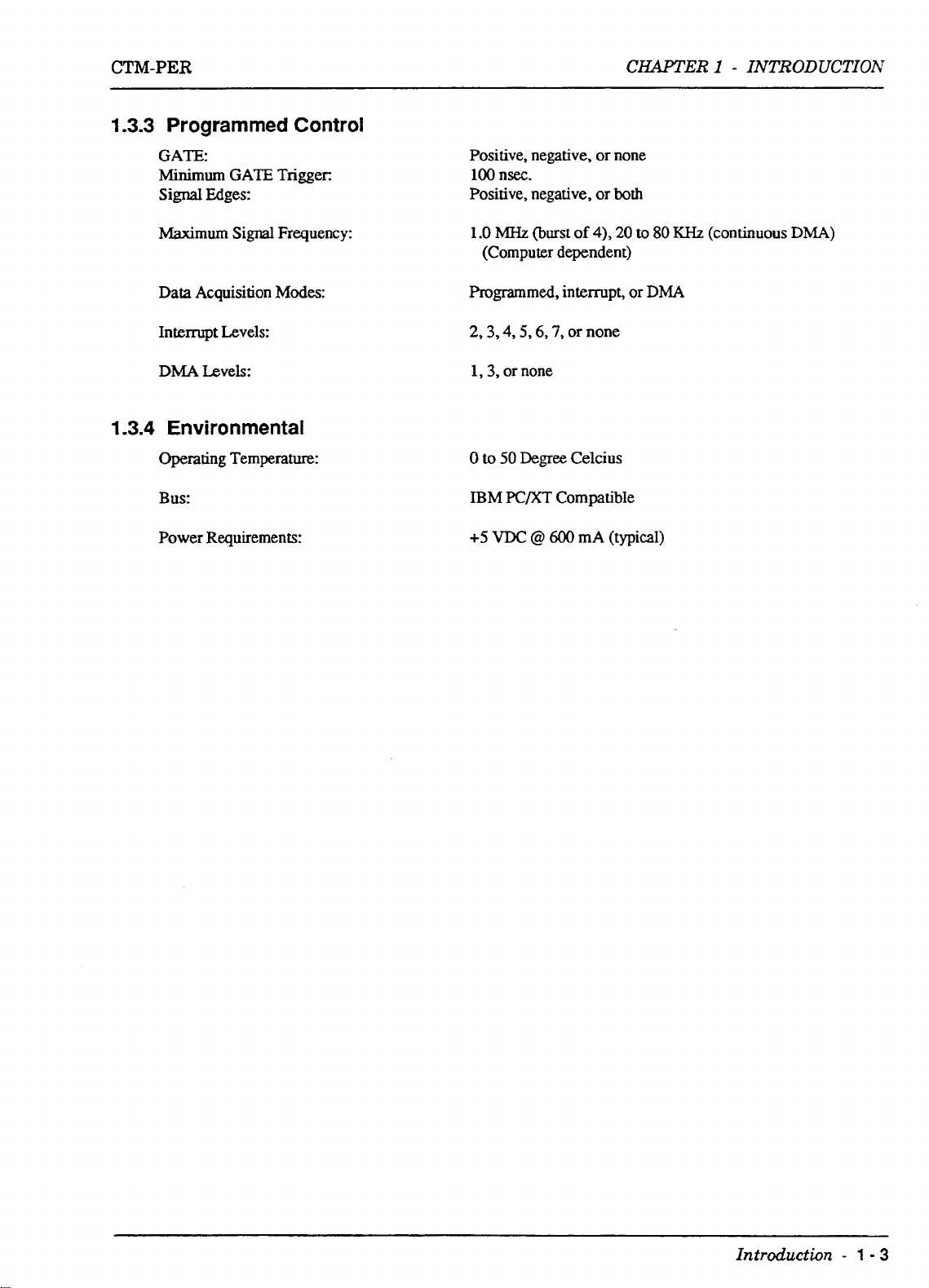
1.3.3
1.3.4
Programmed
GATE:
Minimum
Signal
Maximum Signal Frequency:
Data
Interrupt Levels:
DMA
GATE
Edges:
Acquisition
Levels:
Environmental
Operating Temperature:
Bus:
Power Requirements:
Control
Trigger
Modes:
Positive, negative,
100
nsec.
Positive, negative, or
1
.O
MHz
(burst
(Computer dependent)
Programmed,
2,3,4,5,6,7,
1,3,
or none
0
to
50
Degree
IBM
K/XT
+5
VDC
@
or
of
4),
interrupt,
or
none
Celcius
Compatible
600
mA (typical)
none
both
20
to
or
80
KHz
DMA
(continuous
DMA)
Introduction
-
1
-
3
Page 8

CTM-PER
CHAPTER
2
-
INSTALLATION
&
SETUP
Chapter
INSTALLATION
2.1
CTM-PER
available on a
use, not for resale.
Installation of your CIU-PER Software will require the following procedures:
2.2
Make working copies
in a safe place.
suits
disk
2
&
SETUP
INTRODUCTION
distribution software is on a
3.5"
diskette.
Making a working copy of your CTM-PER Distribution diskette(s).
Unpacking and inspecting the board.
Selecting a Base Address for your CTM-PER driver board.
Installation.
COPYING
your particular computer configuration. The first procedure is for a computer with dual floppy-
drives, the second is for a computer
THE
DISTRIBUTION DISKETTES
To
copy the Distribution diskette(s1,
This
of
your CTM-PER Distribution Software diskettek) and store your original copy
5.25",
360K
floppy diskette
software is licensed to permit multiple copies for non-commeraal
use
a procedure (from the
with
both a floppy- and a hard-disk drive.
(DOS
2.10
format); it is
two
that follow) that
also
2.2.1
2.2.2
Procedure
With your your computer on and booted, place your
1.
the A Drive.
Log
2.
3.
4.
6.
7.
8.
to the A Drive by typing
At
the
Insert the sourcediskette (the CTM-PER Distribution diskette) into the A Drive. The system
will prompt you through the disk copying process, asking
the
B
When you have completed copying, the computer will ask
If
you are copying two diskettes, respond by typing
Y
<Enter> and follow the prompts to copy the second diskette. Otherwise,
Put the original CTM-PER diskettds) in a safe place for storage. Then label your back-up
disk(s) as your CTM-PER working copies.
Procedure
With your computer
1.
files. (In most
The following instructions create
2.
you prefer a name other than
(immediately following).
to that directory, and
DOS
Drive.
for
Dual Floppy-Disk Computers
A:
<Enter>
A>
prompt,
for
Hard-Disk Computers
cases,
type
&DISKCOPY
on
and booted, log to the drive to
this will
go
be
the C Drive.)
a
directory named
W,
substitute your preference in place
If
you intend to use an existing directory,
to Step
3.
A:
B:
<Enter,
DOS
disk containing
you
COPY
be
used for your
CTlM
for the
to insert the
ANOTHER
CTM-PER
CTM-PER
of
skip
these instructions, log
DISKCOPY.EXE
target
(Y/N)?
type
N
Distribution files. If
CTMin
in
diskette into
<Enten.
Distribution
Step a.
a.
Make a
b.
Change to the
CTM
subdirectory by typing
CTh4
directory by typing
MD
CTM
CD
<Enter>
CTM
<Enter>
Installation
&
Setup
-
2
-
1
Page 9

CHAPTER
2
-
INSTALLATION
&
SETUP
CTM-PER
Place the
3.
Type
3.
If copying
5.
With the
safe storage area.
2.3
UNPACKING AND INSPECTING
After you remove the wrapped board from its outer shipping carton, proceed as follows:
1.
2.
3.
4.
You
factory.
CTM-PER
Place one hand firmly on a metal portion of the computer chassis (the computer must
Off and grounded).
package and your body, thereby preventing damage to board components.
Allow
wrapping material.
Inspect
factory.
Check the contents of your mM-PER package against its packing list to
complete. Report any missing items to MetraByte immediately.
may find it advisable to retain the packing material in case the board must
CTU-PER
the copy-all-files command, as
two
Distribution files copied to your hard drive, put the original Utility Diskette(s) in a
a
moment for
the board for signs of damage. If any damage is apparent, return the board to the
Distribution Disk into a floppy Drive
COPY
diskettes, repeat Steps 3 and 4 for the second diskette.
You
place your hand on the chassis to drain off static electricity from the
static
electricity discharge; carefully unwrap the board from its anti-static
&*.*
<Enter>
A.
be
be
be
turned
sure the order is
returned to the
2.4
SELECTING AND SETTING
The
CTM-PER
locations are already occupied by internal I/O and other peripheral cards, you have the option of
resetting the
Base Address switch is located as shown in Figure
Referring to Figure
shown).
requires four consecutive address locations in 1/0 space. Since some 1/0 address
CTM-PER
I/O
base address by means of an on-board Base Address
2-2,
you set the base address on a four-byte boundary to
THE
BASE ADDRESS
2-1,
DIP
DIP
and it appears as shown in Figure
3FC
Hex
7
SWITCH
switch. The
(300
I
2-2.
Hex is
SIGNAL
GATE
2
-
Q
2
-
Figure
Installation
2-1.
CTM-PER
&
Setup
board
outline,
showing
Base
Address
switch
I
location.
Page 10
CTM-PER
CHAPTER 2 -
INSTALLATION
&
SETUP
Figure
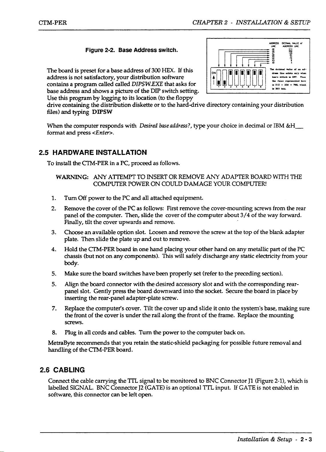
The board is preset for a base address of
address is not satisfactory, your distribution software
contains a program called called
base address and shows a picture of
Use
this
program by logging to its location (to the floppy
drive containing the distribution diskette or to the harddrive directory containing your distribution
files) and typing
When the computer responds with
format and press
2.5
HARDWARE INSTALLATION
To
install the CTM-PER in a PC, proceed as follows.
WAR"G:
Turn
1.
2.
Off
Remove the cover of the PC as follows: First remove the cover-mounting
of
panel
Finally, tilt the cover upwards and remove.
the computer. Then, slide the cover of the computer about
2-2.
Base
Address
DIPSW.EXE
the
DIPSW
Desired
<Enfer>.
ANY
ATTEMPT
COMPUTER POWER ON COULD DAMAGE
power to the
TO
PC
and all attached equipment.
switch.
300
HEX.
that asks for
DIP
switch
base
address?,
INSERT
OR REMOVE
If this
setting.
type
your choice in decimal or
ANY
ADAPTER BOARD
YOUR
COMPUTER!
screws
3/4
of
the way forward.
IBM
WITH
from the rear
&H-
THE
Choose an available option slot. Loosen and remove the screw at the top of the blank adapter
3.
plate. Then slide the plate up and out to remove.
4.
Hold the CI'M-PER
chassis (but not on any components). This will safely discharge any static electricity from your
body.
Make sure the board switches have been properly
5.
Align the board connector with the desired accessory slot and with the corresponding rear-
5.
panel slot. Gently press the board downward into
inserting the rear-panel adapter-plate screw.
Replace the computer's cover. Tilt the cover up and slide it onto the system's base,
7.
of
the front
screws.
Plug
8.
MetraByte recommends that you retain the static-shield packaging for possible future removal and
handling
2.6
CABLING
Connect
labelled SIGNAL.
software, this connector can
of
the cable carrying the
the
in all cords and cables.
the
CTM-PER
BNC
board
in one hand placing your other hand on any metallic part of the PC
set
(refer
to
the preceding section).
the
socket. Secure the board in place by
making
cover is under the rail along the front of the frame. Replace the mounting
Turn
the power to the computer back on.
board.
TTL
Connector
be
left open.
signal to
J2
(GATE) is an optional
be
monitored to BNC Connector
?TL
input. If GATE is not enabled in
J1
(Figure
2-1),
sure
which is
Installation
h
Setup
-
2
-
3
Page 11
CHAPTER
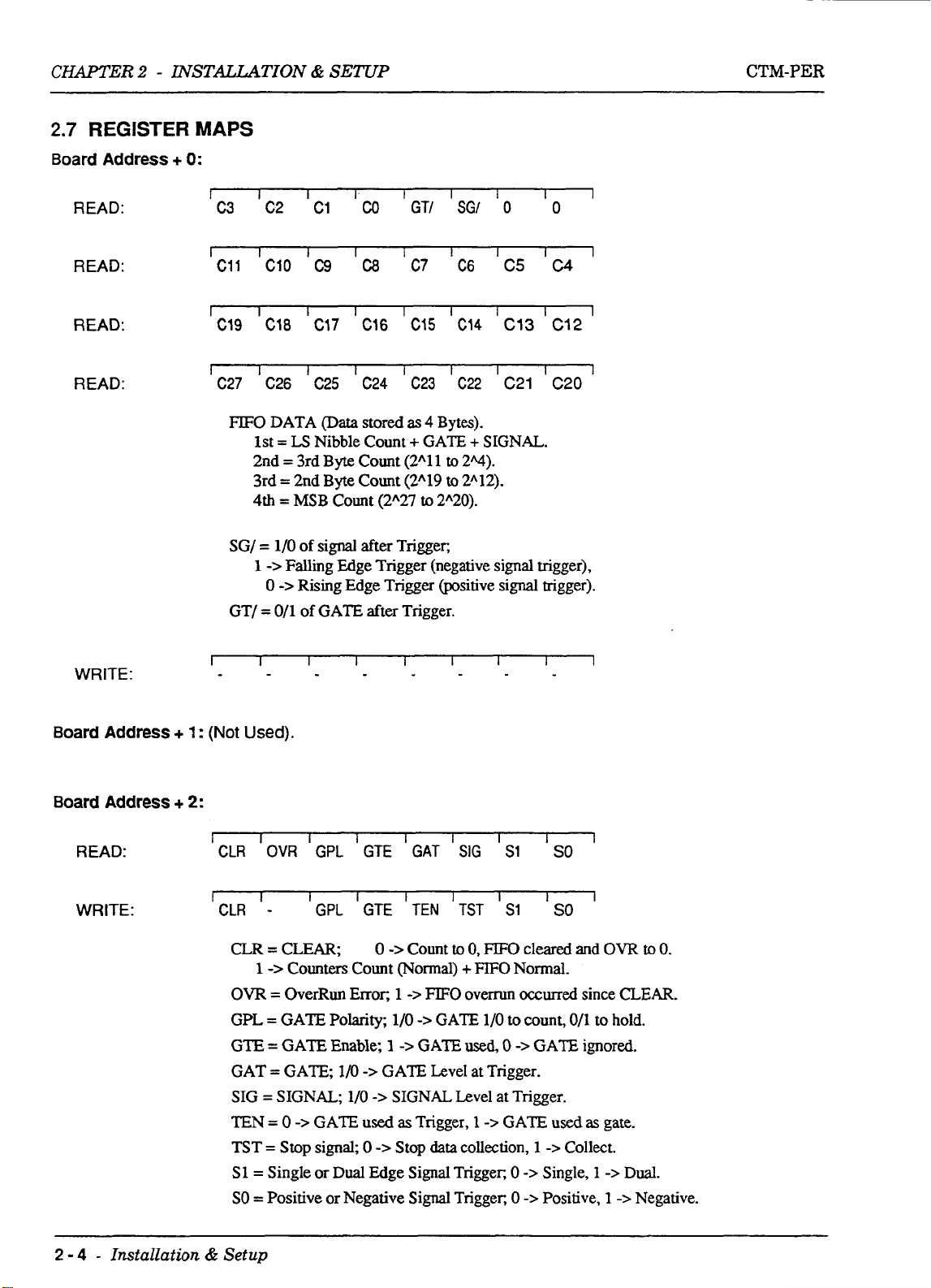
2.7
Board Address + 0:
READ:
READ:
2
-
INSTALLATION
REGISTER
MAPS
I
C3
I
C11
I
I I I I
C2
1
I
C10 C9
&
SETUP
C1
CO
I
C8
GTI 'SGl
I
I
C7 C6
'0
I
C5
I
CTM-PER
I
0
I
C4
READ:
READ:
WRITE:
Board Address
I
Cl9 ICl8 IC17 ICl6
I
1
C27
C26
FIFO
DATA
1st
=
LS
2nd
=
3rd Byte Count (2A1 1
3rd
=
2nd Byte Count (2"19
4th
=
MSB
SG/
=
l/O
of
1
->
Falliig Edge Trigger (negative signal trigger),
0
->
Rising Edge Trigger (positive signal trigger).
GT/
=
O/l
of
I
I
+
1
:
(Not
Used).
'CIS
'C14
IC13
I
1
1
I
C25
@ata
C24
stored
C23
as
4
Bytes).
C22
I
C21
Nibble Count + GATE + SIGNAL.
to
2q).
to
2A12).
Count
(2A27
u)
2"20).
signal after Trigger,
GATE after Trigger.
I
I
I I
1
'C12
I
C20
I
I
1
I
Board Address
READ:
WRITE:
2 - 4
-
Installation & Setup
+
2:
I
I
CLR
r
CLR
OVR
I
-
CLR = CLEAR;
1
->
Co~nter~ Count
OW
=
OverRun
GPL = GATE Polarity;
=
GTE
GAT
SIG
TEN
TST
S1=
SO
GATE Enable;
=
GATE,
=
SIGNAL; 1/0
=
0
=
Stop
Single or
=
Positive or Negative
I
GPL
I
GPL
1/0
->
GATE used
signal,
Dual
I
I
Error,
I
I
TEN
Count
->
FIFO
->
GATE
GATE
Trigger,
data
I I
SIG
I I
TST
to
0,
+FIFO
overrun
used,
collection,
GTE GAT
GTE
0
->
(Normal)
1
1/0
1
->
->
GATE Level at Trigger.
->
SIGNAL Level at Trigger.
as
0
->
Stop
Edge Signal Trigger;
Signal
Trigger,
FIFO
l/O
1
->
I
1
SO
SO
1
'
S1
S1
cleared and
Nom~al.
occurred
to
count, 0/1 to hold.
0
->
GATE
0
->
0
->
since
GATE ignored.
used
as
1
->
Collect.
Single,
Positive,
OVR
CLEAR.
gate.
1
->
Dual.
1
->
Negative.
to
0.
Page 12
CTM-PER
CHAPTER
2
-
INSTALLATION
&
SETUP
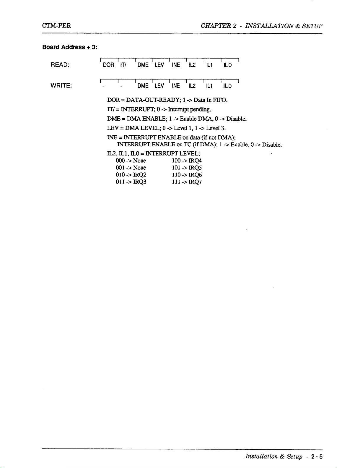
Board
READ:
WRITE:
Address
+
3:
I
I
DOR
IT/
1
I
DOR
=
lT/
=
INTERRm,
DME = DMA
LEV
=
INE = INTERRUPT
INTERRUPT
IL2,
ILl,
OOO
001
010
011
I
I
0
->
0
I
Interrupt
1
->
DME LEV INE
I
DME 'LEV IINE
DATA-OUT-READY;
ENABLE;
DMA
LEVEL;
ENABLE
ENABLE
M3
=
INTERRUPT
->
->
->
->
None
NOW
IRQ2
IRQ3
100
101
110
111
1
IL2
'112
1
->
Data
pending.
->
Enable
Level 1,l
on
data
on
TC
(if
LEVEL;
->
IRQ4
->
IRQS
->
IRQ6
->
IRQ7
I
IL1
I
IL1
In
FIFO.
DMA,
0
->
Level
(if
not
DMA); 1
I
ILO
I
ILO
->
Disable.
3.
DMA);
->
Enable,
I
I
0
->
Disable.
Installation
&
Setup
-
2
-
5
Page 13
CTM-PER
CHeER
3 - PROGRAMMING
Chapter
3
PROGRAMMING
3.1
INTRODUCTION
The
CTM-PER
these are the
have equivalent instructions.
To
simplify program generation, the distribution software contains the I/O driver routine
CTMPERBIN.
covers the majority of common operating modes.
The benefits of using CT"ER.BIN are largely in significant reduction of programming time.
driver
also
or
DMA
available only by using the CALL routines.
3.2
LOADING THE CTMPER.BIN DRIVER ROUTINE (BASIC)
To
use
the CTMPER.BIN driver, load it into memory. Avoid loading it over any part
by another program.
is programmable at the lowest level using input and output instructions.
INPW
supports data collection on interrupt or DMA. Note, however, that BASIC
processing functions, and so-called
and
OUT
X,Y
functions. Assembly language and most other high level languages
This
routine is accessible from BASIC using a single-line CALL statement, and
background
An
example of loading this routine using IBM BASIC is as follows:
data collection using these methods is
In
BASIC
it
The
has
no interrupt
of
memory used
100
CLEAR, 48'1 024
110
DEF SEG=O
SG=256'PEEK(&H511)+PEEK(&H510)
120
SG=SG+48'1024/16
130
DEF SEG=SG
140
BLOAD "CTMPER.BIN",O
150
CTM
160
170
180
A
second option applies when you have memory outside the BASIC workspace; it should
non-IBM BASIC (when the
21 0 DEF SEG=&H7000
220 BLOAD "CTMPER.BIN",O
230
240 DIM D%(15)
250 FIAG%=O
Before you
enough for the CTMPER.BIN file) at the location in line
SEG=&H7000
with another program's use of the memory results in a failure to exit and return from the routine. The
computer
Try
a different memory location until the program works.
PER=O
DIM D%(15) 'DECLARE ARRAY
FLAGY-0 'DECLARE VARIABLE
CTMPER=O
try
loading outside the workspace,
and experiment with loading the CALL routine at other locations. Usually any clash
hangs
up, and the only cure is to switch
PEEKS
of line
120
above will not work).
be
'CONTRACT WORKSPACE
'BASIC WORKSPACE SEGMENT
'LOAD
'LOAD IN ASSEMBLY DRIVER
'DECLARE ARRAY
'DECLARE VARIABLE
sure
you
OFF,
IN
ASSEMBLY DRIVER
really do have unused memory (large
210.
You
can change the line
wait a few seconds, and
TO
48K
210
turn
on the power.
be
DEF
used for
Programming
-
3
-
1
Page 14

CHAPTER
3.3
CALL STATEMENT FORMAT (BASIC)
3
-
PROGRAMMING
CTM-PER
Prior to entering the
subroutine is located. The
xxxxx
CALL
CTMPER(MD%,
C"ER
statement. In
of the
The three variables within brackets are
Mode, as described
(pointers) are passed
pointers from the stack and
exchanged. Four important format requirements must
1.
2.
3.
is the address offset from the current segment of memory,
CALL
routine.
The
CALL
variables, just their locations from the order
always
(mode, data, errors)
The
CALL
the variables on this basis.
You
cannot
statement. For example, the following is an
CALL,
all
the examples, the current segment is defined to correspond with the starting address
in
parameters are positional. The subroutine knows nothing of the names
be
written in the correct order:
routine expects its parameters to
perform
the DEF SEG=SG statement sets the segment address at which the
CALL
This
offset
the following sections.
in
the sequence written to
statement for
D%(O),
FLAG%)
is
therefore zero and
known
the
C"ER.BIN driver must use the form:
as the
On
executing the
BASICS
uses
them
to locate the variables in
of
be
any arithmetic functions within the parameter list brackets of the
illegal
CALL
as
defined in the last DEF SEG
CTMPER=O
CALL
parameters; their meaning depends on the
stack. The
be
met:
their pointers on the stack. The parameters must
integer-type Variables and will write and read to
(see
CALL,
CALL
BASIC's
line
160).
the addresses of the variables
routine unloads these
data space
so
data can
be
of
the
CALL
statement:
CTMPER(MD%+2,D%(0)+8,FLAG%)
CALL
4.
You
cannot
following is
CALL
Apart from these restrictions,
examples are just convenient conventions. Strictly,
CALL.
the
3.4
USE
OF
The following
Modes. Note that
scaled by a power of two and stored as
MD%
parameter in the
MODE
(MDI)
0
1
use
constants for any of the parameters in the
an
illegal
CTMPER(7,2,FLAG%)
statement:
you
can name the integer variables what you want; the names
THE CALL ROUTINE
subsections
delta
contain details and examples of using the
is
defined
CALL
Initialize, store
Start the counter or to stop
interrupts and/or
as
the difference between the current and last data value; the
as follows:
16
bits (an unsigned integer). The Modes are selected by the
FUNCTION
CTM-PER
DMA.
CALL
statement. For example, the
you
should declare the variables before executing
CALL
routine in all ten
base
address, interrupt level, and
the
counter and stop data collection.
(continued on next page)
DMA
in
the
CTM-PER
deZta
level.
shuts
down
is
3
-
2
-
Programming
~ ~ ~~ ~
Page 15

CTM-PER
CHAPl'ER
3
-
PROGRAMMING
MODE
Note that the mode used for data collection depends on what else the computer is
computer's
user
computer and application program in order to establish full performance details.
@ID%)
2
3
4
5
6
7
8
9
10
speed,
vary
the signal frequency, monitor the overrun error, and check the data for his/her particular
and the
Setup gate, edge, and scaling parameters.
Start data collection and return next data.
Start data collection and return array of data.
Start data collection and return array of deltas.
Start data collection of data into memory via interrupt.
Start data collection of deltas into memory via interrupt.
Start data collection of data into memory via DMA.
Transfer data/delta from memory into array.
Check status of data collection.
speed
of the signal being measured. In all cases,
FUNCTION
it
is recommended that the
doing,
the
MODE MODE SPEED
3,43
67
8
3.5
CALL
Mode 0 must always
terminate interrupt or
2
must be called at least once before starting data collection. The normal minimum sequences
are
SEQUENCE
as
follows:
slow (several hundred Hertz)
medium (several thousand Hertz)
high (up to
be
called initially. Mode
DMA
operation when an operation
PROGRAMMED COLLECTION
MODE
0
20
to
80
KHz)
1
is
optional to start
the
sequence and should be used to
is
aborted before normal completion. Mode
OF
DATmELTA
I
MODE
MODE
I
2
3,4,
or
5
of
calls
Programming
-
3-3
Page 16

CHAPTER
3
-
PROGRAMMING
CTM-PER
INTERRUPT
MODE
COLLECTION
0
I
MODE
2
I
MODE
6
or
7
I
MODE
I
10
<
-1
I
MODE
DMA COLLECTION
MODE
MODE
MODE
MODE
I
I
I
9
0
2
8
10
<
OF
done?
OF
DATUDELTA
done?
DATUDELTA
3.6
MODE
3.6.1
Mode 0 checks whether the base
IBM
from
Data
ENTRY:
CALL
MODE
PC.
If
not,
the data array, checked and stored.
is
passed
DESCRIPTIONS
0
-
INITIALIZE
an
error exit occurs. The user-selected interrupt and
in
array:
m
ERRORS:
MODE
F
9
I/O
address
D%(O) = Base I/O address
D%(W
D%(2)
D%(O)
Error
Error
Error
Error #5,
=
Interrupt level
=
DMA
through
#0,
#3,
#4,
is
level
D%(15) - unchanged
no
error
base
I/O
interrupt level not 0 or
DMA
level not 0 or 1 or
in the legal range of
(0
for disabled)
(0
for disabled)
address <255 or
<2
3
>lo20
or
256
DMA
>7
-
1020
(Hex
100
-
3FC)
levels are then unloaded
for the
3
-
4
-
Programming
Page 17

CTM-PER
EXAMPLE:
200
MDY'O
210 D%(0)=768
CALL CTMPER( MDYo,DYo(O)
220
IF FLAG%<>
230
:
D%(1)=3 D%(2)=1
,
FLAG%)
0
MEN GOTO 1000
CHAPTER
3
-
PROGRAMMING
3.6.2 MODE
Mode 1 is used to start or stop the counter. Data collection is not started by this command (only the
clock).
CTM-PER
the data collection
of data collection. The stop command will also shutdown ongoing interrupts or
Data is passed in array:
ENTRY:
Em:
ERRORS:
EXAMPLE:
580
590
600 CALL CTMPER(MD%,D%(O),FLAG%)
0
61
1
-
STARTSTOP
The
stop command clears any pending data out of the
is
stopped, an overrun error is pending. The clock may also
modes;
MDY-1
DYo(O)=O 'O=STOP ELSESTART CLOCK
IF
FLAG%<> 0 MEN GOTO 1000
MODE 1 is
Clock
used
to start the clock
D%(O)
D%(O) through D%(15) - unchanged
Error
Error
Error
=
0
for stop, else for start
#0,
no error
#1,
driver not initialized
#6,
overrun error pending
FIFO.
only if
An
error is reported
be
turned on through one of
it is to
be
started prior to the start
DMA
if,
operations.
when the
3.6.3 MODE
Mode
2
is used
SCALING
used to reduce
Data is passed
ENTRY:
factor for deltas. Data collection is not actually started with this mode. The scaling factor is
where
EXIT:
2
-
Setup
to setup (or change) the
the
Tg)
TaV1)
SCALE
in
array:-
GATE,
delta count to
=
current count
=
last count
=
D%(4)
D%(O) = Gate enable, 1 for gate
D%(U = Gate polarity,
D%(2)
D%(3)
D%(4)
D%(5)
D%(O) through D%(14)
D%(15)
EDGES,
16
bits of resolution.
parameter
=
Edges,
=
If single edge,
=
Scaling factor power of 2
=
0
-
SCALING
EDGE
control word (for debug
and
(0
to 28)
0
->
single,
->
gate as trigger,
GATE
parameters -3r data collection and the
used
1/0
for
1/0
active
1->
dual
0
->
pos.,
1
->
neg.
(0
to 28)
1
->
gate as gate
-
unchanged
use
only)
Programming
-
3-5
Page 18

CHAPTER
ERRORS:
EXAMPLE:
250
MD%=2
D%(O)=O 'O=NOT GATED,
260
D%(1)=0 'GATE
270
D%(2)=0
280
290
300
31
320
330
340
350
360
370
D%(3)=0
D%(4)=0 'SCALE FACTOR
D%(5)=0 'O=TRIGGERED,
0
CALL CTMPER( M D%, D%(O), FLAG%)
IF
3
-
PROGRAMMING
Error
#0,
no
#1,
Error
Error
Error
POLARITY
'EDGES, OzSINGLE l=BOTH
'IF
SINGLE EDGE,
driver not initialized
#7,
illegal gate parameters
#8,
illegal scale factor
1
=GATE USED
1/0
O=POS
FOR
1
=GATED
'NOTE: DELTAS ARE 0.1 MICROSECONDS COUNTS TO 65535.
'IN
OTHER WORDS, PERIODS TO 6.5535 MILLISECONDS CAN
'MEASURED WITHOUT SCALING.
'MEASURED, D%(4) CAN BE SET TO ANY POWER
FLAG%<> 0 THEN GOT0 1000
error
FOR 1/0 ACTIVE
1
=NEG
DELTA MEASUREMENT
IF
LONGER PERIODS ARE TO BE
OF
2,O
TO
CTM-PER
BE
28.
GATE
SIGNAL,
CLEAR
COUNT
DATA
DELTA
Figure
GATE
SIGNAL
CLEAR
COUNT
DATA
DELTA
---loo
2-3.
GATE
---loo
1
I I I
-200-
I
180
I
180
and
SIGNAL
GATE
used as
I I
--200--
I I
180
I
180
GATE,
I
---3oo--
I
270
I
90
waveforms
I
330 390
I
60
with
4w-
1
I
60
GATE
Enabled, positive polarity,
single-positive-edge triggering.
---3C)o--
270
I
90
I
I
330 390
I
60
I I
-400--
I
I
60
I I
5C)o----@-
I
450
I
I
510
I
60 60
I
500
I
450
I
60
I
510
I
60
I
L
I
_____
o--
3
Figure
-
6
-
Programming
2-4.
GATE
GATE
and
used
SIGNAL
waveforms with
as
Trigger, single-positive-edge triggering.
GATE
Enabled, positive polarity,
Page 19

CTM-PER
CHAPTER
3
-
PROGMMZVG
3.6.4
MODE
Mode 3 is
to keep
started, will produce an immediate return to calling program
Data
is
ENTRY
EMT:
ERRORS:
used
up
with
passed
3
-
Data Collection, Single
to collect data, one point at a time, under program control. The program must be able
the data or else an overrun error will occur. Pressing any key, once Mode 3 is
in
array:
D%(O) = Last LSB
D%(l) = Last 3rd Byte (2"11 to 2"4)
=
D%(2)
D%(3)
D%(O) = Current
D%(1) = Current 3rd Byte (2"11 to 2"4)
D%(2)
D%(3)
D%(4)
D%(5) through D%(15)
Error
Error
Error
Error
Error
Error
Last 2rd Byte (2"19 to 2"12)
=
Last MSB (2"27 to 2"ZO)
=
Current 2rd Byte (2"19 to 2"12)
=
Current MSB (P27 to 2"20)
=
Current scaled DELTA (unsigned integer)
#0,
no error
#1,
driver not initialized
#6,
overrun error
#9,
control not setup (Mode 2
#lo,
DELTA overflow, >65535
NOTE:
#11,
Keyboard termination
(2"3
to 2"0, GAT/, SIG/,
LSB
(2"3 to 2"0,
-
pending
D%(O) to D%(3) set correctly,
with
GAT/,
unchanged
error code
SIG/,
call)
11.
00)
00)
DELTA,
D%(4), set to
0
3.6.5
Mode
two words
2"O bit
F'IFO
error
Mode
Data
ENTRY:
EXIT:
ERRORS:
MODE
4
(the 2"27 bit to 2"12 bit). The program must
will
4
is
4
-
Data Collection, Multiple
is
used
to collect an array of data under program control. Data
of
the integer array. The first word being the
plus
GATE/, SIGNAL/, and
occur. The data is
is
started, will produce an immediate return to calling program with error code
passed
in array:
passed
D%(O) = Number of conversions required
D%(1)
D%(2)
D%(O) through D%(15)
Error
Error
Error
Error #9, control not setup (Mode
Error
Error #12, Sample count
two
zeros). The second word being the next
as
two
successive words in the array. Pressing any key, once
NOTE:
=
=
#0,
#1,
#6,
#11,
Array size (integer words) must
number of conversions
Segment of array
Offset of array
no error
driver not initialized
overrun error pending
Keyboard termination
first
two
be
able to keep up with the data or else
(-1
if caller's segment)
-
unchanged
2
0
or negative
is
bytes out
call)
stored
of
the
be
in
the array
FlFO
(the 2"11 bit to
two
bytes out of the
twice the
11.
using
an
overrun
Programming - 3
-
7
Page 20

CHAPTER
EXAMPLE:
DIM
100
MD%=4
180
Do/o(0)=l
190
200
21
220
CALL
IF FLAG%
0
FOR
IF
230
NEXT
240
FOR
250
T=INT(X(I)/16)+X(l+l)'4096
260
PRINT T
270
NEXT
280
3
-
PROGRAMMING
XYo(
1
9)
,X(
1
0
:
D%(l)=-1
CTMPER( M
<>
0
1=0
TO
19
X%(l)<O
THEN X(1)=65536!+Xo/o(i)
1=0
TO
18
9)
Do/,(2)=VARPTR(Xo/o(0))
D%,D%(
THEN GOTO
STEP
0)
2
,FLAG%)
1000
ELSE
CTM-PER
X(I)=X0/o(l)
3.6.6
MODE
Mode 5 is
up
with
Note that the DELTA overflow error is not indicated in
mro. The delta
started, produces
Data
is
ENTRY:
EXIT:
ERRORS:
EXAMPLE
5
-
Data Collection, Multiple Delta
used
to collect an array of deltas under program control. The program must
the data or else an overrun error will occur.
has
passed
been scaled
an
immediate return to calling program with Error Code
in
array:
by
the parameter setup in Mode
D%(O)
D%(1)
D%(2)
D%(O) through
Error
Error
Error
Error
Error
Error
=
Number
=
Segment
=
Offset
of
D%(15)
#0,
no
error
#1,
driver not initialized
#6,
overrun error pending
#9,
control not setup (Mode 2 call)
#11,
Keyboard termination
#12,
Sample
An
initial value
this
mode but the DELTA value comes out
of
conversion DELTAS required
of
array
(-1
if
caller's segment)
array
-
unchanged
count 0 or negative
of
zero for the data
2.
Pressing any key, once Mode
11.
be
is
able to
keep
assumed.
5
is
MD%=5
200
D0/0(0)=20
21
0
CALL
220
IF
230
240
250
260
270
3.6.7
Mode
up
3
-
8
FLAG%oO THEN GOTO
FOR
IF
X%(l)<O THEN X=65536!+X%(I) ELSE X=X%(I)
PRINT XZASCALING
NEXT
MODE
6
is
used
with the data or else an overrun error will occur. MODE 9 can
-
Programming
:
D'Xo(l)=-l
CTMPER( MD%,DO/(O),
1=0
TO
19
6
-
Data Collection Via Interrupt
to collect data into memory
D%(2)=VARPTR(XO/o(O))
FLAG%)
1000
via
interrupt control. The program must be able to
be
used to move
the
data
keep
(two
Page 21
CTM-PER
~~ ~
successive words) or deltas (one word), into
when the sample count is done or when
an
array. Data collection is stopped and the
an
overrun is encountered.
CHAPTER
3
-
PROGRAMMING
FWO
cleared
Data is
ENTRY:
m
ERRORS:
210
220
230
240
passed
in array:-
D%(O)
D%(1) = Segment of MEMORY
D%(2)
D%(3)
D%(O) through
Error
Error
Error
Error
Error #12, Sample count
Error #13, DMAhterrupt already active
Error
MD%=6
D%(O)=20 : D%(l)=&H7000 : D%(2)=0 : D%(3)=0
CALL
IF
=
Number of conversion required
NOTE:
(four times in
=
=
0
1
#O,
#1,
#6,
#9,
#16,
C”MPER(MD%,D%(O>,FLAG%)
FLAG%oO
MEMORY size in words must
bytes)
Offset
of MEMORY to receive data
Recycle flag:
->
Non-recycle, done flag set after number
->
Recycle, samples continuously written and rewritten
D%(1)5
no error
Driver not initialized
Overrun error pending
Control not setup (Mode 2 call)
Interrupt must be installed for this mode.
THEN GOT0
-
unchanged
0
or negative
lo00
be
(-1
if caller’s segment)
twice D%(O)
of
samples
3.6.8
MODE
Mode 7 is
must
be
Deltas, passed
sample count
zero is
overflow.
Data is
ENTRY
EXIT:
7
-
Delta Collection
used
to collect Deltas (one unsigned integer word) into memory via interrupt. The program
able to keep
as
one word, into an array. Data collection is stopped and the
is
done or when an overrun is encountered. For collection of Deltas, an initial value
used.
Deltas greater then
passed
in
array:
Via
Interrupt
up
with the data or an overrun error occurs. MODE 9 can
65535
are indicated by a zero, no other error flag is used for the Delta
D%(O)
D%(1)
D%(2)
D%(3)
DWO) through D%(15) - unchanged
=
Number of conversions required
=
Segment of MEMORY
=
Offset of MEMORY to receive data
=
Recycle flag
0
->
Non-recycle, done flag set after
number of samples
1
->
Recycle, samples continuously written
and re-written
(-1
if caller’s segment)
be
used
FIFO
cleared when the
to move the
of
Programming - 3-9
Page 22

CHAPTER
ERRORS:
EXAMPLE:
210 MD0/o=7
220
230 CALL CTMPER( MD%,DO/o(O),FLAG%)
240
3
-
PROGRAMMING
#0,
Error
Error
#1,
#6,
Error
Error
#9,
#12,
Error
Error
#13,
Error
#16,
D%(O)=ZO
IF FLAGO/ooO THEN GOTO 1000
:
D%(l)=&H7000 Do/0(2)=0
no error
Driver not initialized
Overmn error pending
Control
Sample count 0 or negative
DMA/Intermpt already active
Interrupt must
not setup (Mode 2 call)
be
installed for this mode.
D%(3)=0
CTM-PER
3.6.9
MODE
Mode 8 is
MODE
array.
Data is passed
ENTRY
EXIT
ERRORS:
9
8
-
Data
used
to collect data via
can
be
used
in
array:
Collection
to move the data or Deltas, passed as two successive words or one word, into an
D%(O)
D%(1)
D%(2)
D%(3)
D%(O)
Error
Error
Error
Error
Error
Error
Error
Via
DMA
DMA.
NOTE: two words (four bytes)
In general, this is the mode normally used to collect data.
=
Number of samples required
=
went of MEMORY
=
Offset of
=
Recycle
0
->
Non-recycle, done
1
->
Recycle, samples continuously written
through D%(15) - unchanged
#0,
no error
#1,
Driver not initialized
#6,
Overrun error pending
#9,
Control not setup (Mode 2 call)
#12,
Sample count 0 or negative
#13,
DMADnterrupt already active
#15,
DMA
MEMORY
flag
number of samples
and rewritten
wrap around of page
to
flag
(1
to
(-1
if
caller's segment)
receive data
per
sample
set after
16384)
3
21
220
230
-
240
250
260
270
280
290
10
EXAMPLE:
0
MD%=8
:
D%(0)=1024
CALL CTMPER( MD%,D%(
IF FLAG%<>O THEN
MD%=lO
CTMPER(MD'?'o,D%(O),FLAG%)
CALL
IF D%(O)o 1 THEN GOTO 2000
PRINT "SAMPLE COUNT
IF
D%(1)=1 THEN GOTO 260
-
Programming
D%(l)=&H7000
GOTO
D%(2)=0
0)
,FLAG%)
1000
=
";D%(2)
:
D%(3)=0
'MUST BE DMA OPERATION
'WAIT ON DONE
Page 23

CTM-PER
CHAPTER 3 -
PROGRAMMING
3.6.10
MODE
Mode 9 transfers data from any segment/offset
Data
can
used
is
zero.
can
be
used
Data
is
passed
ENTRY:
9
-
Transfer
be
converted in the process from data to Deltas.
NOTE
to convert data to Delta for any language.
ALSO
in array:
From
that for languages other than
D%(O)
D%(1)
D%(2)
D%(3)
D%(4)
D%(5)
Memory
=
Number
=
Source segment in memory
=
Source offset in memory
=
Starting sample offset number
0
to
0
to
=
segment
=
Offset of destination array
NO’TE:
=
D%(6)
data/DELTA
0
->
1
->
2
->
To
Array
of
memory to an integer array in
of samples
32767
for deltas
16383
for data
offset
(bytes)
(bytes)
offset
of
Two
One array
NOTE
BASIC,
=
samples
=
samples
destination array
array
(2
words) positions per data
(1
word) position per delta
that the initial value of the count
this
mode
to
transfer
(1
*
2
for deltas
*
4
for data
(-1
if
flag
data
DELTA
data available, convert to DELTA
BASIC‘s
is
not usually needed; it
to 32767)
caller’s segment)
workspace.
m
ERRORS:
EXAMPLE:
31
0
320
330
340
360
370
380
390
3.6.1 1
Mode 10
D%(O) through D%(1)5
Error
#0,
no
Error #1, Driver not initialized
Error #14, Illegal start offset or number of samples.
#lo,
Error
DELTA overflow, >65536
NOTE:
MD%=9
D%(O)=20
D%(4)=-1
CALL CTMPER( MD%,D%(O)
FOR
IF
X0/o(l)<O THEN X=65536!+X%(I) ELSE
PRINT X
NEXT
MODE
is
:
D%(l)=&H7000 : D%(2)=0
:
D%(S)=VARPTR(X”/o(O)) D%(6)=2
,FLAG%)
1=0
TO 19
10
-
Monitor Status
used
to
monitor the status of the data collection during interrupt or DMA operations.
-
unchanged
error
Non-fatal, DELTA set to
D%(3)=0
X=X%(I)
0
is
Data
ENTRY.
passed in array:
D%(O) through D%(15) - not used
Programming
-
3 - 11
Page 24

CHAPTER3
-
PROGRAMMING
CTM-PER
EXIT:
D%(O)
D%(1)
D%(2)
D%(3) = Error
D%(4)
D%(5) = Read
ERRORS
Error
Error
EXAMPLE:
250 MD%=lO
260 CALL
270
280 PRINT "SAMPLE COUNT
290
CTMPER(MD'Yo,D'Xo(O),FLAG%)
IF
D%(O)<> 1 THEN GOTO 2000
IF
D%(l)=l THEN GOTO
=
Type
0
=
none
1
=
DMA
2
=
interrupt
=
Status
0 = done
1
=
active
=
Current sample count
inactive, cleared
0 = no error
1
=
overrun error
=
Read
see
register map
see
register map
#0,
no error
#1,
Driver not initialized
=
";D%(2)
260
'WAIT ON
of
operation (last or current)
or
programed
or
inactive
flag
(set
only
after status
by
this mode
of
ba-2
of
base+3 (intenupt/DMA register)
'MUST BE DMA OPERATION
(control
DONE
register)
D%U)
..or..
250 MD'Y'l
260 CALL CTMPER( M D%,D%(O) , FLAG%)
270 IF Do/O(0)o
280 PRINT "SAMPLE COUNT
290
IF D%(l)=l THEN GOTO 260
0
2
THEN GOTO 2000
=
";D0h(2)
'MUST BE INTERRUPT
'WAIT ON DONE
3
-
12
-
Programming
Page 25

CTM-PER
CHmER
4
-
CALIBRATION & TEST
Chapter
4
CALIBRATION
The
CTM-PER
can
be
checked using
the SIGNAL input
that
you use a very stable and accurate source for
board requires no adjustments. Accuracy
of
&
TEST
an
external counter on the
the board
and
allowing the
10
h4Hz
Crystal or by inputting
CTM-PER
this
purpose.
is
soley a function the
to measure the
10
a
periods.
MHz
Crystal
known
It
is important
and
frequency to
Calibration & Test
-
4
-
1
Page 26
CTM-PER
CHAPTER
5
-
FACTORY
RETURN
INFORMATION
Chapter
5
FACTORY RETURN INFORMATION
Before returning any equipment for repair, please call
service personnel. If possible, a technical representative will diagnose and resolve your problem
telephone. If a telephone resolution is not possible, the technical representative will issue
Return Material Authorization
RMA
the
container.
Note that
invoice number and date
When returning equipment for repair, please include the following information:
1.
2.
3.
Repackage the equipment. Handle it with ground protection; use its original anti-static wrapping, if
possible.
number in any documentation regarding the equipment and on the outside of the shipping
if
you are submitting your equipment for repair under warranty,
Your
name, address, and telephone number.
The invoice number and date of equipment purchase.
A
description of the problem or its symptoms.
of
purchase.
(RMA)
number and ask you to return the equipment. Please reference
508/880-3OOO
to notify MetraByte's technical
you
you
must
furnish
by
a
the
Ship the equipment to
Be
sure
to
reference the
Rh4A
Repair
Keithley MetraByte
440
Myles
Taunton, Massachusetts
Telephone
FAX
number on
Department
Standish Boulevard
508/8803000
Telex
503989
508/880-0179
the
outside of the package!
02780
Factory Return Information
-
5
-
1
Page 27

CTM-PER
APPENDlX
A
-
SUMMARY
OF
ERROR
CODES
Appendix
SUMMARY
Error
A
codes
OF
are returned
CODE
0
1
2
3
4
5
6
7
8
9
10
11
12
13
14
15
16
ERROR
No
Errors
Driver not
Mode number
Invalid
Interrupt level out of range, not
DMA level not
Overrun error encountered.
Illegal gate parameters
Illegal scale factor
Control not setup (Mode
DELTA overflow,
Keyboard ternination
Sample count
DMA/Intermpt already active
Illegal
start
DMA
wrap
This
mode needs
CODES
in
the
FLAG%
ERROR
initialized.
c0
or
base
address,
0
or
0
or
offset or number
around
an
variable
DESCRIPTION
>N.
a56
or
1
or
3.
2
call)
>65535
negative
of
of page
Interrupt (can't
as
follows:
>1020.
0
or
c2
samples
be
or
0)
>7
Summary
of
Error
Codes
-
A
-
1
Page 28

CTM-PER
APPENDIX
B - CTM-PER DRIVERS
Appendix
B
CTM-PER:
B.l
B.2
B.3
B.4
B.5
CTM-PER General Description
Microsoft 'C'
Program
Borland Turbo
Program
Microsoft PASCAL (V3.0
Borland Turbo PASCAL (V3.0
Program
PASCAL,
&
Quick 'C': Small Model; Medium Model; Large Model; Microsoft 'C' Example
'C'
(V1
C, FORTRAN DRIVERS FOR CTM-PER
TABLE
.O
-
2.0):
Small Model; Medium Model; Large Model; Turbo C Example
-
4.0): Medium Model; Microsoft PASCAL Example Program
-
OF
CONTENTS
4.0): Compact Model; Large Model;
Turbo
PASCAL Example
B
.6
8.7
B
.8
B
.9
B.10
Microsoft FORTRAN (V4.0 & Higher): Large Model; INOUT.FOR Function Example Program;
or
Integer Function
Lahey Personal FORTRAN (V1
Lahey Personal FORTRAN Example Program
Interpreted BASIC
Program
QUICK BASIC: Medium Model; QUICK BASIC Example Program
CTMPER.LIB General Purpose Library; File Listing for CTM-PER
Subroutine; Microsoft FORTRAN Example Program
.O
&
Higher): Large Model; Integer Function or Subroutine;
(GW,
COMPAQ, IBM, etc.): Medium Model; Interpreted BASIC Example
CTM-PER Drivers
-
B
-
1
Page 29

APPENDLX
B.1
INTRODUCTION
B
-
CTM-PER
DRWERS
CTM-PER
B.l.l
B.1.2
CTM-PER
Keithley MetraByte's CTM-PER is a programming tool for writing data acquisition and control
routines
the following languages; Microsoft C
Microsoft PASCAL
Personal Fortran
&
supported language.
supported language, and it includes an example program at the end of each language section. Full
source listings are included in the distribution software.
operating MODES, PARAMETERS, and
in
higher).
General Description
Pascal,
CTM-PER
C,
and
(V3.0-4.01,
(V1.0-2.0),
consists of several assembly-language drivers and example programs for each
This
Fortran for for the CI'M-PER. CTM-PER supports
(V4.0-5.11,
Turbo PASCAL
QuickBASIC
Section is structured to illustrate useage for each memory model of each
(V4.0
ERROR
Microsoft Quick-C
(V3.0-5.0),
&
higher), and
codes before attempting CTM-PER implementation.
Microsoft
You
W1.0-2.0),
FORTRAN
GW,
COMPAQ, and
should
be
all
memory models for
Turbo
familiar with the board's
C
(V1.0-2.0),
(V4.0-4.1),
IBM
BASIC
Lahey
Implementation
Software drivers of the CIU-PER are limited to the actual language interface for the supported
languages.
contain a very brief introductory explanation followed
interface driver (implemented via a CALL statement) consists of three positiondependent parameters,
namely MODE, ARGUMENT (or
by
the board.
error number,
To
simplify programming
PARAM
if
any, corresponding to selected MODE.
is the function-dependent arguments required for execution. FLAG is the
and
PARAM),
illustrate actual language interface, the following sections
and
FLAG.
by
an actual example for each language. Each
MODE is the
type
of
function to
be
executed
W2.0
B - 2
-
CTM-PER
Drivers
Page 30
CTM-PER
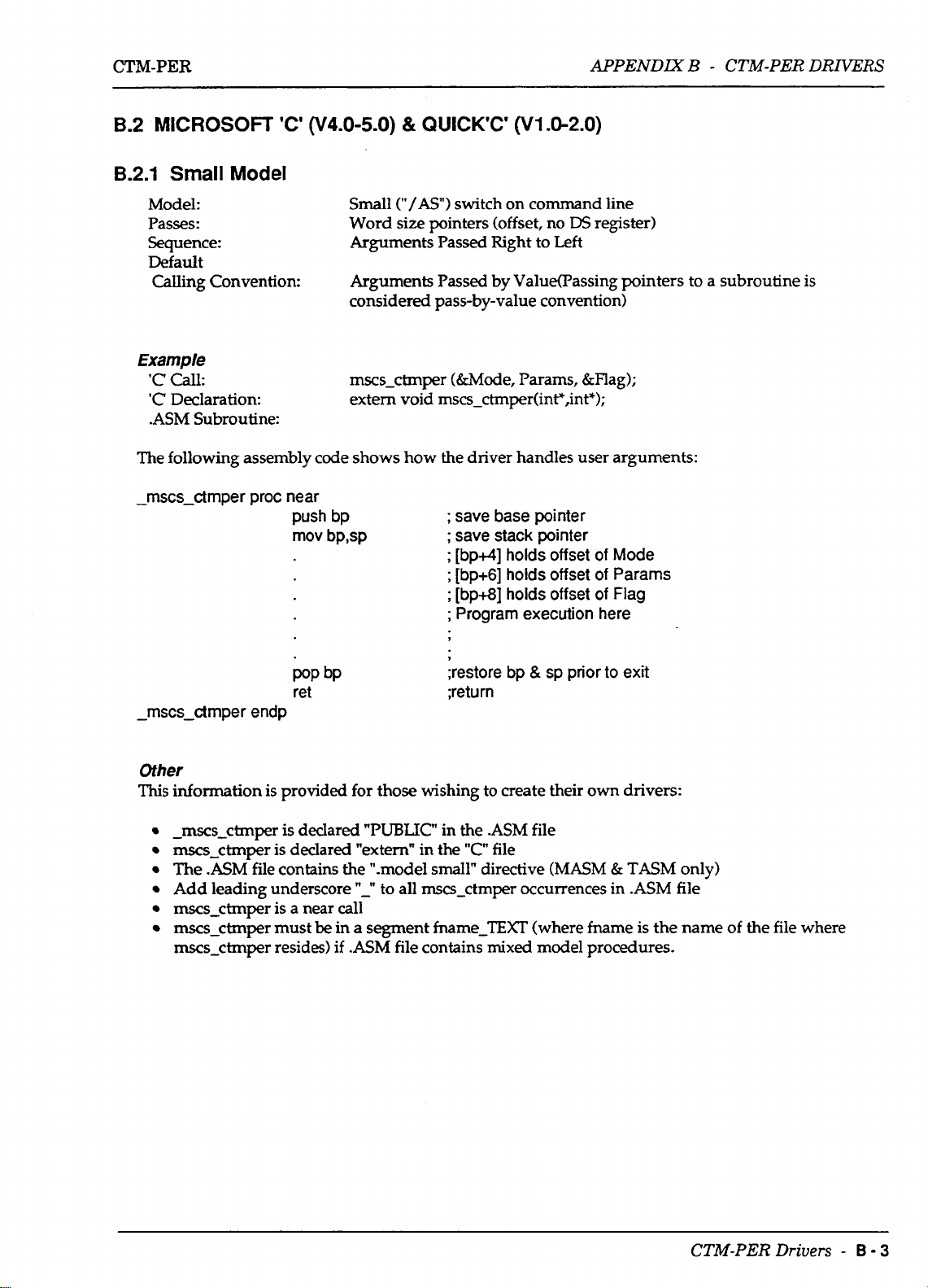
B.2
MICROSOFT
'C'
014.0-5.0)
&
QUICK'C'
APPENDIX
(V1 .O-2.0)
B
-
CTM-PER
DRIVERS
8.2.1
Small
Model:
Passes:
Sequence:
Default
Calling Convention:
Example
'C
call:
'C
Declaration: extem void mscs-ctmper(int*,int*);
.ASM Subroutine:
The following assembly code shows how the driver handles user arguments:
-
mscs-ctmper proc near
Model
push bp
mov bp,sp
Small
("/AS")
Word size pointers (offset, no
Arguments Passed Right to Left
Arguments Passed by ValuefFassing pointers to a subroutine is
considered pass-by-value convention)
mscs-ctmper (&Mode, Params, &Hag);
switch on command line
DS
register)
;
save base pointer
;
save stack pointer
;
[bp+4] holds offset
;
[bp+6] holds offset
;
[bp+8] holds offset
;
Program execution here
of
of
of
Mode
Params
Flag
bP
pop
ret
-
mscs-ctrnper endp
Other
This
information is provided for those wishing to create their
-
mscs-ctmper
mscs-ctmper
The
.ASM
Add leading underscore
mscs-ctmper is a near
mscs-ctmper must
mscs-ctmper resides) if
is
declared
is
declared "extem" in the
file contains the ".model
"PUBLIC"
"-I'
to all mscs-ctmper occurrences in
call
be
in
a segment fname-IEXT (where fname is the name of the file where
.ASM
file contains mixed model procedures.
;restore bp
;return
in the .ASM file
"C"
file
small"
directive (MASM & TASM only)
&
sp prior to exit
own
drivers:
.ASM
file
CTM-PER
Drivers
-
B
-
3
Page 31

APPENDLY
B - CTM-PER DRNERS
CTM-PER
8.2.2
Medium
Model:
Passes:
Sequence:
Model
Medium
Word
("/AM")
size
pointers (offset, no
switch on command line
DS
Arguments Passed Right to Left
register)
Default
by
Calling Convention:
Arguments Passed
Value
Example
'C
call:
'C
Declaration: extem void
mscm-ctmper (&Mode, Params, &Flag);
mscm_ctmper(int*,int*,int*);
.ASM Subroutine:
The following assembly code shows how the driver handles user arguments:
;
far
CALL
-
mscm-ctmper proc far
push bp
mov bp,sp
;
save base pointer
;
save stack pointer
;
[bp+6] holds offset
;
[bp+8] holds offset
;
[bp+l
;
Program execution here
9
(dword return address)
of
Mode
of
Params
01
holds offset of Flag
POP bP
ret
-
mscm-ctmper endp
Other
This
information is provided for those wishing
-
mscm-ctmper is declared
"PUBLIC"
mscm-ctmper is declared "extern" in the
;restore bp
;return
to
create their own drivers:
in
the
.ASM
"C"
file
sp prior
file
to
&
The .ASM file contains the ".model medium" directive (MASM & TASM
Add leading underscore
"-"
to all man-ctmper occurrences in
mscm-ctmper is a far call
mscm-dmper must
be
in a segment fname-TEXT (where fname
mscm-ctmper resides), else Linker returns an error.
exit
.ASM
file
is
the name
only)
of
the file where
B
-
4
-
CTM-PER
Drivers
Page 32

CTM-PER
APPENDIX
B - CTM-PER DRNERS
B.2.3
Large
Model:
Passes:
Sequence:
Model
Large
dword
("/AL")
size
switch on command line
pointers (offset and
Arguments Passed Right to Left
DS
register)
Default
Calling Convention:
Arguments
Passed by Value
Example
'C
Call:
'C
Declaration: extem void
.ASM
Subroutine:
mscm-ctmper (&Mode, Params, &Flag);
mscl_ctmper(ine,int*,ints);
The following assembly code shows how the driver handles user arguments:
;
far
CALL
-
rnscl-ctrnper proc far
push bp
rnov bp,sp
;
save base pointer
;
save stack pointer
;
[bp+6] holds offset
;
[bp+l
;
[bp+l4] holds off set
;
Program execution here
,
(dword return address)
of
Mode
01
holds off set of Params
of
Flag
pop bP
ret ;return
-
rnscl-ctrnper endp
Other
This
information is provided for those wishing to create their
-
mscl_ctmper
mscl-ctmper
The .ASM file contains the
Add leading underscore
is
declared
is
declared "extern" in the
"PUBLIC'
".model
'I-"
to all mscl-ctmper occurrences in .ASM file
;restore bp & sp prior
in the
.ASM
"C"
file
large" directive (MASM
mscl-ctmper is a far call
mxm-ctmper must
mscl-ctmper resides), else Linker returns
be
in a segment fname-TEXT (where fname is the name of the file where
an
file
error.
to
own
exit
drivers:
&
TASM
only)
~~ ~
CTM-PER Drivers
-
B
-
5
Page 33

APPENDIX
B - CTM-PER DRIVERS
CTM-PER
8.2.4
Microsoft
#include "stdi0.h"
#include "coni0.h"
extern
main()
rnscm-ctrnper(int*,int',int*);
I
int Mode, Flag, Pararns[l5];
P
Initialize CTM-PER using Mode
Mode
=
0;
Pararns[O]
Pararns[l]
Params[2]
Pararns[3]
=
=
=
=
768;
2;
3;
0;
'C'
Example
0
r
declare driver call
r
Base Address
P
Interrupt
P
DMA level
r
No
Auto-Calibration
of
Board
level
rnscrn-ct mper( &Mode, Pa rams, &Flag)
if
(Flag
!=O)
{
printf("\n\nMode 0 Error FLag = O/odn",Flag);
1
REMAINDER OF
CODE
;
B-6
-
CTM-PERDn'uers
Page 34

CTM-PER
B.3
BORLAND
TURBO
'C'
(V1.0-2.0)
APPENDIX
B - CTM-PER
DRNERS
B.3.1
Small
Model:
Passes:
Sequence:
Default
Calling Convention:
Example
'C
call:
'C
Declaration: extern void
.ASM
The following assembly code shows
-
tcs-ctrnper proc near
Model
Subroutine:
push
rnov
bp
bp,sp
Small
("-ms")
word size pointers (offset, no
Arguments Passed Right
Arguments Passed by Value
tcs-ctmpr (&Mode, Params, &Flag);
switch on command line
DS
register)
to
Left
tcs_ctmper(int*,int*,int*);
how
the driver handles user arguments:
;
save base pointer
;
save stack pointer
;
[bp+4]
;
[bp+6]
;
[bp+8]
;
holds
offset
of
holds
offset
of
holds
off set
of
Program execution here
Mode
Params
Flag
pop
bP
ret
-
tcs-ctrnper endp
Other
This
information is provided for those wishing
-
tcs-ctmper is declared "PUBLIC' in the
tcs-ctmper is declared "extern" in the
The
.ASM
file contains the ".model small" directive (MASM & TASM only)
Add leading underscore
tcs-ctmper is a near call
tcs-ctmper must
tcs-ctmper resides), else Linker returns an error.
be
"-"
to all tcs-ctmper occurrences in .ASM file
in a segment fname-TEXT (where fname is the name
;restore
;return
to
.ASM
"C"
file
bp
&
sp
prior to exit
create their
file
own
drivers:
of
the file where
CTM-PER
Drivers
-
B
-
7
Page 35

APPENDIX
B
-
CTM-PER DRNERS
CTM-PER
B.3.2
Medium Model
Model:
Passes:
Sequence:
Default
Calling Convention:
Example
'C
call:
'C
Declaration: extern void
.ASM Subroutine:
following
The
-
tcm-ctmper proc far
-
tcm-ct mpe r e
Medium
word
Arguments Passed Right to Left
Arguments Passed by Value
tcm-ctmper (&Mode, Params, &Flag);
assembly code shows how the driver handles user arguments:
push
bp
mov
bp,sp
POP
bP
("-mm")
size
pointers (offset, no
switch on command line
tcm_ctmper(inrc,int*,int*);
;
Word pointer return address
;
save base pointer
;
save stack pointer
;
[bp+6] holds offset
;
[bp+8] holds offset
;
[bp+l
01
holds
;
Program execution here
,
t
;restore
bp
&
off
sp
DS
register)
of
Mode
of
Params
set
of
Flag
prior to exit
ret ;return
ndp
Other
This
information is provided for those wishing to create their
.
-
tcm-ctmper is declared
tan-ctmper is declared "extem" in the "C"
The
.ASM
file contains the ".model medium" directive
Add
leading
tan-ctmper is a near call
tan-ctmper must
tan-ctmper resides), else Linker returns an error.
underscore
be
"PUBLIC"
"-"
to all tan-ctrnper occurrences in
in a segment fname-TEXT (where fname
in the
.ASM
file
own
file
(MASM & TASM
drivers:
only)
.ASM
file
is
the name of the file where
8-8
-
CTM-PERDrivers
Page 36

CTM-PER
APPENDIX
B
-
CTM-PER DRNERS
B.3.3
Large
Model:
Passes:
Sequence:
Default
Calling Convention:
Example
'C
call:
'C
Declaration: extern void
.ASM Subroutine:
The
following assembly code shows how the driver handles user arguments:
-
tcl-ctmper proc far ; Word pointer return address
Model
Large
dword size pointers (offset, no
Arguments Passed Right to Left
Arguments Passed by Value
tcl-ctmper (&Mode, Params, &Flag);
push bp
mov bp,sp
("-ml")
tcl_ctm~r(int+,inec,int*);
switch on command line
DS
register)
;
save base pointer
;
save stack pointer
;
[bp+6] holds offset
;
[bp+l
01
holds off set
;
[bp+l4] holds
;
Program execution here
off
set
of
of
of
Mode
Params
Flag
POP bP
ret
-
tcl-ctmper endp
Other
This
information
-
tcl-ctmper is declared
td-ctmper is declared "extern" in the
The
.ASM
Add leading underscore
Both code & data
tcl-ctmper must be in a segment fname-TEXT (where fname is the name of the file where
tcl-ctmper resides), else Linker returns an error.
is
provided for those wishing to create their own drivers:
"PUBLIC"
file
contains the ".model large" directive
"-"
to all tcl-ctmper occurrences in
use
dword (segment/offset) pointers
;restore bp & sp prior to exit
;return
in the
.ASM
file
"C"
file
(MASM
&
TASM
.ASM
only)
file
CTM-PER Drivers
-
B
-
9
Page 37

APPENDLY
B
-
CTM-PER DRIVERS
CTM-PER
B.3.4
Turbo
..........................................................................
f
TCEXAMPLE-C
CTM-PER EXAMPLE OF MODE
f
f
USING TURBO C MEDIUM MODEL
f******************t***********************************************~**~*~
#include "stdi0.h"
##include "conio.h"
extern
main()
'C' Example
0
tcm-ctrnper(int*,int*,int*);
I
int Mode, Flag, Params[ 151;
f
initialize CTM-PER using Mode
Mode = 0;
Params[O]
Params[l] = 2;
Params[2]
Params[3] = 0;
=
=
768;
3;
0
/
f
declare driver call
f
Base Address
P
Interrupt level
P
DMA level
f
No Auto-Calibration
of
Board
tcm-ctmper(&Mode, Params, &Flag);
if(
Flag
!=O)
{
printf(ln\nMode 0 Error FLag = %d\n",Flag);
1
REMAINDER OF CODE
B
-
10
-
CTM-PER
Drivers
Page 38

CTM-PER
B.4
MICROSOFT
PASCAL
(V3.0-4.0)
APPENDDZ
B
-
CTM-PER
DRIVERS
8.4.1
Medium
Model:
Passes:
Sequence:
Default
Calling Convention:
Model
Medium
word sue pointers (offset address only)
Arguments Passed Left to Right
Arguments Passed by Value
Example
=
PASCAL Call:
'C'
Declaration:
.ASM Subroutine:
The following assembly code shows how
msp-ctmper proc far ; far call (dword return address)
push bp
mov bp,sp; save stack pointer
Result
FUNCTION
integer):integer;extemal;
mspdmper (Varl, Var2, Var3);
msp-ctmper(VAR Var1:integer;VA.R Var2;VAR Var3:
the
;
save base pointer
;
[bp+4] holds offset of Mode
;
[bp+6] holds offset of Params
;
[bp+8] holds offset of Flag
;
Program execution here
driver handles
user
arguments:
,
;
Return Value for Function In
,
;
return and pop bp & sp values prior to exit
msp-ctrnper endp
mov ax,n
pop bP
ret
6
Other
This
information
msp-ctmper is declared "PUBLIC" in the .ASM file
msp-ctmper
msp-ctmper resides in segment-TEXT (default
is
provided for those wishing to create their
is
declared external in the calling program
own
drivers:
of
the .model command)
ax
register
CTM-PER
Drivers
-
B
-
11
Page 39

APPEND=
B
-
CTM-PER DRIVERS
CTM-PER
Parray = array[l ..16]
Var
Params
Mode,Flag
Result
(*
Define Driver Function Call
FUNCTION msp-ctmper(VAR Mode:integer;VAR Params:Parray;VAR
:
Parray;
:
integer;
:
integer;
of
word;
*)
F1ag:integer):INTEGER;EXTERN;
(*
MAIN
*)
BEGIN
Mode:=
Params[l]:=
Params[2]:=
Params[S]:=
Params[4]:=
0;
r
768;
2;
3;
0;
Result:= rnsp-ctmperf Mode,Params,Flag);
if(Result
c>
0)
then
WriteLn('Mode
Base Address of Board
0
Error
#
=
',Result);
*)
(*
Interrupt level
DMA
level
*)
r
No Auto-Calibration
*)
*)
REMAINDER
END.
B
-
12
-
CTM-PER
OF
CODE
Drivers
Page 40
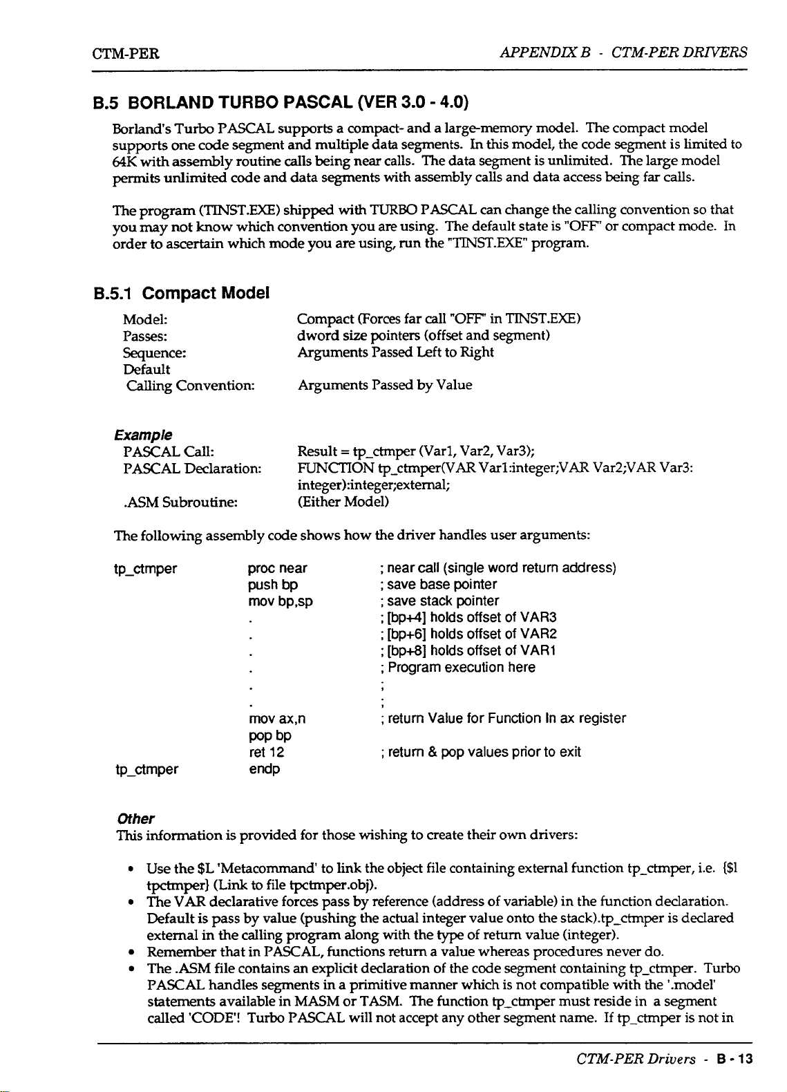
CTM-PER
APPEND= B -
CTM-PER
DRIVERS
B.5 BORLAND TURBO PASCAL (VER
Borlands Turbo PASCAL supports a compact- and a large-memory model. The compact model
supports one code segment and multiple data segments. In
64K
with assembly routine calls being near calls. The data segment is unlimited. The large model
permits unlimited code and data segments with assembly calls and data access being
The program
you
may
order to ascertain which mode you are using, run the
B.5.1 Compact
Model:
Passes:
Sequence:
Default
Calling
Example
PASCAL Call:
PASCAL Declaration:
(TINST.EXE)
not
know
Model
Convention:
shipped with
which convention you are using. The default state is
Compact (Forces far call
dword
Arguments Passed Left to Right
Arguments Passed by Value
Result
size
=
tp-ctmper (Varl, Var2, Var3);
FUNCTION
3.0
-
4.0)
this
model, the code segment is limited
far
TURBO
pointers (offset and segment)
tp-ctmper(VAR Var1:integer;VA.R Var2;VAR Var3:
PASCAL can change the calling convention
"OFF'
or compact mode.
"TINST.EXE"
"OFF"
program.
in
TlNST.EXE)
integer):integer;external;
.ASM Subroutine: (Either Model)
calls.
so
to
that
In
The following assembly code shows how the driver handles user arguments:
;
tp-ctmper proc near
push bp
mov bpsp
near call (single
;
save base pointer
;
save stack pointer
;
[bp+4]
;
[bp+6] holds offset
;
[bp+8]
;
Program execution here
holds
holds
word
offset
offset
return address)
of
VAR3
of
VAR2
of
VAR1
.
;
mov ax,n
POP bP
12
ret
tp-ctmper endp
return Value
;
return & pop values prior
Other
This
information is provided for those wishing to create their
Use the $L 'Metacommand to link the object file containing external function tp-ctmper, i.e. ($1
tpctmper} (Link to file tpctmper.obj).
The
VAR
declarative forces pass by reference (address
is
Default
external in the calling program along with the
Remember that in PASCAL, functions return a value whereas procedures never do.
The .ASM file contains
PASCAL handles segments
statements available in
called 'CODE!
pass by value (pushing the actual integer value onto the stackhtp-ctmper is declared
an
explicit declaration of the code segment containing tp-ctmper. Turbo
in
a primitive manner which is not compatible with the '.model'
MASM
Turbo
PASCAL will not accept any other segment name.
~~ ~
-~
or
TASM.
The function tp-ctmper must reside in a segment
for
Function In
to
own
drivers:
of
variable) in the function declaration.
type
of return value (integer).
ax
register
exit
If
CTM-PER
tp-ctmper is not in
Drivers
-
B
-
13
Page 41

APPENDIX B - CTM-PER DRIVERS
segment "the linker returns an "unresolved external" error. The Segment Declaration for "CODE"
in
the
.ASM
file must appear as:
CTM-PER
CODE SEGMENT
ASSUME CS:CODE
CODE ENDS
B.5.2
Large
Model
Model:
Passes:
Sequence:
Default
Calling
Convention:
Example
PASCALcalk
PASCAL Declaration:
.ASM
Subroutine: (Either Model)
The following assembly code shows
WORD
Large (Forces far call
dword
size
pointers (offset and segment)
PUBLIC
;
CODE GOES HERE
"ON
in
TINST-EXE)
Arguments Passed Left to Right
Arguments Passed
=
Result
tp-ctmper (Varl, Var2, Var3);
FUNCTION
by
Value
tp-ctmper(VAR Var1:integer;VAR Var2;VAR Var3:
integer1:integer;external;
how
the driver handles user arguments:
tp-ctmper proc near
push bp
mov bp,sp
mov ax,n
pop bP
ret 12
tp-ctmper
Other
This
information is provided for
0
Use
the $L 'Metacommand to link the
tpctmper)
0
The
VAR
Default
external
0
Remember that
0
The
is
in
.ASM
endp
(Link
to file tpctmper.obj).
declarative forces pass by reference (address of variable) in the function declaration.
pass
by
value (pushing
the calling program along with the
in
PASCAL,
file contains
an
;far
call
(dword return address)
;
save base pointer
;
save stack pointer
;
[bp+4]
;
[bw] holds offset of
;
Ibp+l2]
;
Program execution here
holds
holds
offset of
off
set
VAR3
VAR2
of
VARl
.
1
;
return Value for Function
;
return & pop values prior to exit
those
wishing to create their
object
file containing external function tp-ctmper, i.e. {Sl
the
actual integer value onto the stackhtp-ctmper is declared
type
own
of return value (integer).
functions return a value whereas procedures never
explicit declaration of the code segment containing tp-ctmper.
In
ax
drivers:
register
do.
B
-
14
-
CTM-PER
Drivers
Page 42
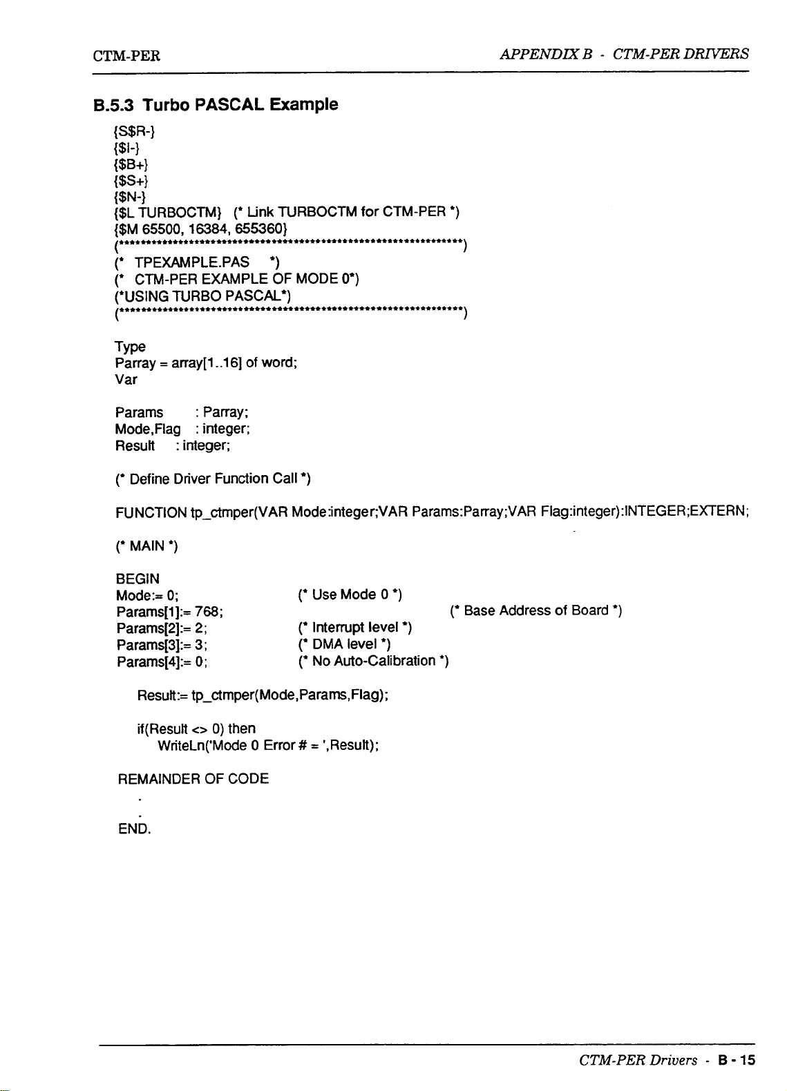
CTM-PER
APPENDlX B -
CTM-PER
DRIVERS
B.5.3
Turbo
{S$R-}
{$I-}
PASCAL
Example
W+}
{SS+}
{$N-1
{$L TURBOCTM}
{$M 65500,16384,655360)
(**~*~*****~~~*+**********++********+***********+********++++**+
(+
TPEXAMPLE.PAS
CN-PER EXAMPLE
(*
(+USING
(*+**~~*~+****~+*+***+****+**************+**+**********+********
Type
Parray
Var
Params
Mode,Flag
Result
(+
TURBO PASCAL.)
=
anay[l
:
integer;
Define Driver Function Call
..lS]
:
Parray;
:
integer;
(*
Link TURBOCTM for CTM-PER
*)
OF
MODE
of word;
0')
*)
*)
1
1
FUNCTION tp-ctmper(VAR M0de:integer:VAR Params:Parray;VAR
(*
MAIN
*)
BEGIN
(*
Mode:=
Params[l]:=
Params[2]:=
Params[3]:= 3;
Params[4]:=
REMAINDER
END.
0;
768;
2;
0;
Result:= tp-ctmper( Mode, Params, Flag)
if(ResuR
C>
0)
then
WriteLn('Mode
OF
CODE
0
Error
Use Mode
(+
Interrupt level
(+
DMA level
(+
No
Auto-Calibration
#
=
',Result);
0
+)
;
*)
Base Address of Board
*)
*)
F1ag:integer):INTEGER;EXTERN;
*)
~~ ~
CTM-PER
Drivers
-
B
-
15
Page 43

CTM-PER
APPENDIX
B
-
CTM-PER DRIVERS
B.6.2
FORTRAN INOUT-FOR Function
C
INOUT.FOR
Example for using INBYT 8 OUTBYT Functions
C
program inout
integer'2 port,outdat
integer'l indat
pOrt=O
outdat=O
do
35 i=l,10,1
(',lo)
write
10 format('Enter
read(*,l5)
15 format(i3)
write(',20)
20 format(' Enter data to write(-1
read(*,25) outdat
25 format(i3)
Port
Address(Decima1):
port
=
exit)
Example
')
')
if(outdat
write (',30) outdat
30 format(' Data Written
call outbyt(port,outdat)
indat=inbyt(port)
35 wrlte(*,40) indat
40 format(' Data Read
45 end
8.6.3
Integer
(Default)
The following assembly
fctmper proc far
.EQ.
-1) go to
Function
code
shows how the driver handles user arguments:
push bp
mov bp,sp
=
=
',z)
',z)
45
or
Subroutine
;
Word pointer return address
;
save base pointer
;
save stack pointer
;
[bp+6] holds offset of VAR3
;
[bp+l
01
holds offset of VAR2
;
[bp+l4] holds offset
;
Program execution here
of
VARl
mov ax,n
POP
ret
fctmper endp
bP
;
return Value for Function In
ax
register
CTM-PER Drivers
-
B
-
17
Page 44

CTM-PER
B.7
LAHEY PERSONAL FORTRAN
(V1.0
&
HIGHER)
APPENDIX
B - CTM-PER DRIVERS
8.7.1
Large
Model: Large
Passes:
Sequence:
Default
Calling Convention:
Model
(Only Model Available)
Example
FORTRAN Call:
FORTRAN Declaration:
.ASM Subroutines:
NOTE:
FORTRAN integer functions (those beginning with the letters i,
the ax register, whereas non-integer functions reserve
to
pointer
location bp+lO after the "push bp" and "mov bp,sp" instructions have been executed.
MetraByte's FORTRAN
this is not a problem. Using non-integer functions may become a problem when
returning pointers, floating point results, long integers, etc.
use the IMPUCIT
implicitly
the returned result. Non-integer functions pass their arguments starting at
type
dword
Arguments Passed Left to Right (Opposite
Arguments Passed by Reference
call lhy-ctmper(Var1, Var2, Var3);
None
undeclared subroutines or functions are external. It is left to the linking
process to provide the required
name should conform to
integer unless expressly declared otherwise.
size
pointers (offset and
necessary
<-->
Assembly routines predominantly use
INTEGER
(A-Z) which causes all Functions and Variables to be
in
FORTRAN
DS
register)
MS)
source file (Fortran assumes that
.LIB
or
.OBJ
files. However, the function
ANSI
FORTRAN rules for integer functions.
j,
or
k)
return results in
4
bytes on the calling stack for a far
type
To
avoid undue problems,
integer
so
that
Also
note that FORTRAN
passed parameters onto the stack at the time of the call to any function or subroutine
rather than the parameters themselves.
8.7.2
Integer (Default) Function or Subroutine
The following assembly code shows how the driver handles user arguments:
Ihy-ctmper proc far
push bp
mov
bpm
POP bP
ret
Ihy-ctmper endp
NOTES
1.
VAR3 = Return Value
2.
Function lhy-ctmper must
Calls
By
Reference.
;
dword pointer return address
;
save base pointer
;
save stack pointer
;
[bp+6] holds offset of VAR3
;
[bp+lO] holds offset of VAR2
;
[bp+14] holds offset
;
Program execution here
I
;
Restore bp
of
Function.
be
declared as an integer
&
This
sp
method places the address of the
of
VARl
prior
to
exit
*
2.
CTM-PER Drivers
-
B
-
19
Page 45
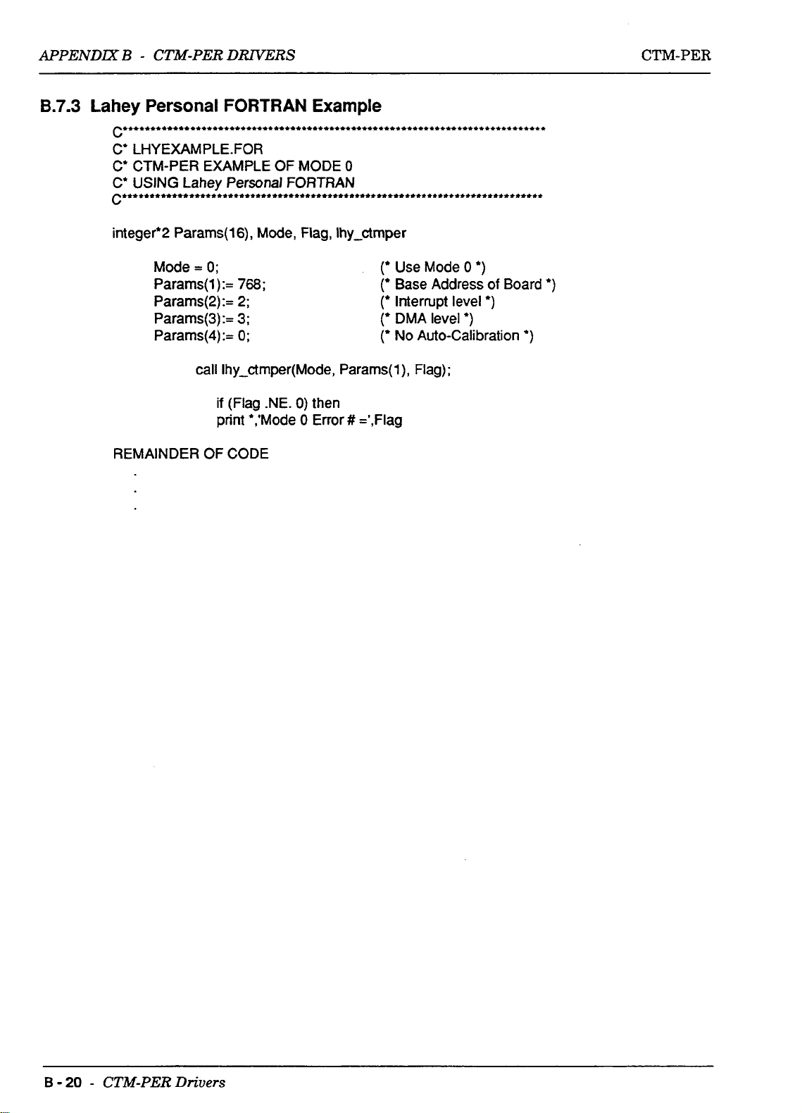
APPEND=
B - CTM-PER
DRWERS
CTM-PER
integer*2 Params(
Mode
Params(
Params(2):= 2;
Params(3):= 3;
Params(4):=
REMAINDER OF CODE
16),
=
0;
1 ) :=
768
0;
call Ihy-ctmper(Mode, Params(l), Flag);
if
(Flag .NE.
print *,'Mode
Mode,
;
Flag, Ihy-ctmper
0)
then
0
Error
#
=',Flag
(*
Use Mode
r
Base Address
(*
Interrupt level
r
DMA level
(*
No Auto-Calibration
0
*)
*)
of
*)
Board
*)
*)
B
-
20
-
CTM-PER
Drivers
Page 46
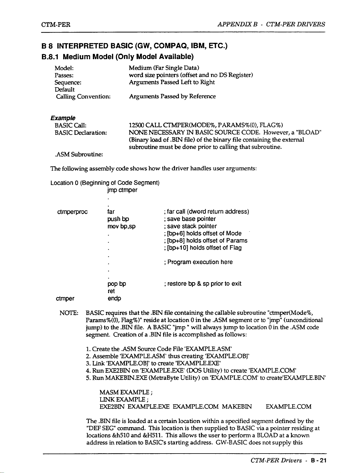
CTM-PER
APPENDIX
B
-
CTM-PER DRIVERS
B 8 INTERPRETED
B.8.1 Medium Model
Model: Medium (Far Single Data)
Passes:
Sequence:
Default
Calling Convention:
BASIC
(Only
word
Arguments Passed
Arguments
(GW,
COMPAQ, IBM,
Model Available)
size
pointers (offset and no DS Register)
Left
Passed
by Reference
ETC.)
to Right
Example
1250
BASIC Call:
BASIC Declaration:
.ASM Subroutine:
The following assembly code shows how the driver handles user arguments:
Location 0 (Beginning
ctrnperproc far
of
Code Segment)
jrnp ctrnper
push bp
mov bpsp
CALL CTMPER(MODE%,
NONE
(Binary load of .BIN file)
subroutine must
NECESSARY
be
done prior to calling that subroutine.
;
far call (dword return address)
;
save base pointer
;
save stack pointer
;
[bp+6] holds offset
;
[bp+8] holds offset
;
[bp+l
01
IN
holds offset of Flag
BASIC SOURCE CODE. However,
of
PARAMS%(O),
the binary file containing the external
of
Mode
of
Params
FLAG%)
a
"BLOAD"
ctrnper
NOTE:
;
Program execution here
;
POP
bP
ret
endp
BASIC requires that the .BIN file containing the callable subroutine "ctmper(Mode%,
Params%(O), Flag%)" reside at location
jump) to the .BIN file.
segment. Creation of a .BIN file is accomplished as follows:
1.
Create the .ASM Source Code File 'EXAMPLE.ASM
2.
Assemble
3.
Link
4.
Run EXE2BIN on 'EXAMPLE.EXE'
5.
Run
MASM
LINK
EXE2BIN
The
.BIN
"DEF SEG command.
locations
address in relation to BASIC's starting address. GW-BASIC does not supply this
'EXAMPLE.ASM
'EXAMPLE.0BJ'
MAKEBNEXE
EXAMPLE
EXAMPLE
EXAMPLE-EXE DOUIFLE.COM MAKEBIN EXAMPLE.COM
file
is
loaded at a certain location within a specified segment defined by the
&h510
A
(MetraByte Utility) on 'EXAMPLE.COM to create'EXAMPLE.BN
;
This
and
&H511.
restore
BASIC "imp " will always jump to location 0 in the .ASM
thus
to
create 'EXAMPLE.EXE'
;
location is then supplied to BASIC via a pointer residing at
This allows the user to
bp
&
sp
prior
to
exit
0
in the .ASM segment or to "imp" (unconditional
creating 'EXAMPLEOBJ'
(DOS
Utility) to create 'EXAMPLE.COM'
perform
a BLOAD at a known
code
CTM-PER Drivers
-
B
-
21
Page 47
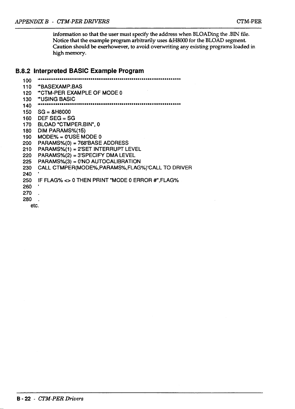
APPENDIX
B
-
CTM-PER
DRZVERS
CTM-PER
8.8.2
100
110
120
1
30
140
150
160
170
180
190
200
21
220
225
230
240
250
260
270
280
information
so
that the user must
Notice that the example program arbitrarily uses
Caution should
high
memory.
Interpreted
,****t**t**ttt**~*~.*****t*~***t*tt********~****~**tt**********.******
'*BAS EXAM P . BAS
"CTM-PER EXAMPLE OF MODE
'*USING BASIC
~***,**t*tt*tCtt**********t**tt*t**t*+*******************+t**********
=
&H8000
SG
DEF
SEG
BLOAD "CTMPER.BIN",
DIM PARAMSYo(15)
MODEYo
PARAMS%(O) = 768'BASE ADDRESS
PARAMSYo(1)
0
PARAMSYo(2)
PARAMSYo(3)
CTMPER(MODEYo,PARAMS%,FLAGO/o)'CALL
CALL
I
IF FLAGYO
BASIC
=
SG
=
O'USE MODE
=
=
=
<>
0
be
exerhowever, to avoid overwriting
Example Program
0
0
2'SET INTERRUPT LEVEL
3'SPECIN DMA LEVEL
O"O
AUTOCALIBRATION
THEN
PRINT "MODE 0 ERROR #",FLAG%
etc.
0
specify
the
address when BLOADing the .BIN file.
&H8000
TO DRIVER
for
the BLOAD segment.
any
existing programs loaded
in
B
-
22
-
CTM-PER
Drivers
Page 48

CTM-PER
B.9
QUICK
BASIC
APPENDIX B -
CTM-PER
DRNERS
B.9.1
Medium Model
Model:
Passes:
Sequence:
Default
Calling Convention:
Example
BASIC Call:
BASIC Declaration:
.ASM Subroutine:
(Only
Model Available)
Medium (Far Single Data)
word
size
pointers (offset and
is
Left
the
the
only
To
make use of
Arguments Passed
Arguments Passed by Reference
CALL QBC"ER(MODE%, VARPTR(PARAMS%(O)),
The Declaration tells QuickBASIC that the subroutine expects
arguments and that
Remember that BASIC normally passes all arguments by reference
(address).
BASIC passing the value of the address of the array in effect passes the
array by reference.
".QLB" (Quick Library) file is created out of the original
Although the format of the subroutine
interpreted BASIC packages, both the Quick BASIC integrated
development environment (QB.EXE) and the command line complier
(BCEXE)
library file. Unlike interpreted BASIC packages, Quick BASIC actually
links
"jmp
interpreted BASIC.
This
expect the subroutine to
to the assembly .QLB library file
QBCTMPER" instruction at location 0 (of the
no
DS Register)
to Right
middle
argument is to
method for passing
the
be
in a specially formatted .QLB
so
FLAG%)
be
passed
an
callable assembly routine, a
is
identical to those
it is not necessary to include the
array
source
by
value.
to
a subroutine
.ASM
used
file) as in
three
in
source file.
by
The following assembly code shows how the driver handles user arguments:
QBCTMPER proc far
push bp
rnov bp,sp
pop bP
ret
QBCTMPER endp
NOTE
When creating a .QLB file, it
backup file. Creation of a .QLB file is accomplished as follows:
1.
Create the
2.
Assemble
3.
Link
MASM
LINK
.ASM
'EXAMPLEASM'
'EXAMPLEOBJ' with the
EXAMPLE;
/q
Source Code File 'EXAMPLE.ASM'
EXAMPLE
;
far call (dword return address)
;
save base pointer
;
save stack pointer
;
[bp+6]
;
[bp+8]
;
[bp+l 01
;
;
restore bp &
is
;
holds offset of Mode
holds
offset
of
holds offset
Program execution here
sp
good
practice to make a .LIB of the same version as a
thus creating 'EXAMPLE.OBJ'
"/q"
option to create
of
prior to exit
Pararns
Flag
'EXAMPLE.QLB
CTM-PER
Drivers
-
B
-
23
Page 49

CTM-PER
Linking the Library "ctmper.lib" to
including it
link
userprog.obj,userprog,,user.iib-ctmper.lib;
in
the link line
as
follows:
APPENDIXB - CTM-PER
from
Call
:
:
Call
:
Call
:
Call
:
Call
:
Call
:
Call
:
Call
:
Call
:
Call
the
user program is accomplished after program compilation by
Microsoft C Small Model
from
Microsoft C
from
Microsoft C Large Model
from
Turbo C Small Model
from
Turbo
from
Turbo C Large Model
from
Microsoft PASCAL
from
Microsoft QuickBASIC
from
Microsoft FORTRAN
from
Lahey FORTRAN
C
Medium
Medium
Model
Model
DRIVERS
userprog.obj is an object module produced by compilation
userprog should
user-lib is any other user library,
For TurboPASCAL, the entry point is:
The user program should have the directive
{$L
turboctrn}
B.10.2
Files
FILE NAME
FILES.DOC
PCFCTMPER.DOC
README-DOC
MSCDEMO.EXE
TPDEMO.D(E
MSPDEMO.EXE
Link in
Listing
CTMPER.LIB
TURBOCTM.OBJ
be
used
for the resultant executable
turboctrn.obj
for
CTM-PER
File Listing
Information concerning mu1 ti-language call structures
REV.
Microsoft
Turbo PASCAL example
Microsoft PASCAL example of Mode
Driver for
CTM-PER Driver for Turbo PAS
30
1
.EXE
if
applicable
:
Call
from
DESCRIF'TION
Information on CTM-PER
"C"
example of Mode 3 usage
of
Mode 3 usage
"C",
PASCAL, and FORTRAN
of
the user program
file
TurboPASCAL program
3
usage
B.10.3
Source
FILE NAME DESCRIPTION
CTMPER. ASM
CTMPERPCF.ASM
MSCDEM0.C
TCDEM0.C
TPDEMOPAS
MSPDEMO.PAS
MSFDEMO-FOR
LHYDEMO.FOR
DEM0G.C
DEM06L.C
C,
PASCAL,
and
FORTRAN
Source code CTM-PER Driver (Common Modes)
CTM-PER Source code Language Interface
Microsoft
Turbo
Turbo PASCAL example of Mode
Microsoft
Microsoft FORTRAN example of Mode
Lahey Fortran Example of Mode
Microsoft
Microsoft
"C"
example
"C"
example of Mode 3 usage
PASCAL
"C"
"C",
example of Mode 3 usage
Example of Mode
Large Model Example
Programs
of
Mode 3 usage
3
6
3
usage
usage
of
3
usage
Mode
CTM-PER
6
Drivers
-
B
-
25
 Loading...