

Page 1

KPC-TM
and
KPC488.2TM
Trigger MasterTM
Interfaces
Page 2

Page 3

User Guide
for the for the
KPGTM and KPC488.2TM KPGTM and KPC488.2TM
Trigger Master”” Trigger Master””
--
Interfaces Interfaces
Copvrishfl Kdtbley Data Acquisilicm 1993
KEITHLEY DATA ACQUlSlTiON - Keithley MetraSyWAsyst
440 Myles Slandiih Blvd., Taunton, MA 02780
RwisionA-FebntaylSS8
ParI Number: 24461
TEL 508/880-3000, FAX 508/880.0179
-3-
Page 4

Warranty Information
All products manufactured by KeithIey Data Acquisition are warrantedagsinst defective materials and
workmanship foraperiodofone year from thedateof delivery to theoriginalpurchaser. Any product
that is found to be defective within the warranty period will, at the option of the manufacmrer, be
repaired or replaced. This warnutty does not apply M products damaged by improper use,
Warning
Keithley Data Acquisition assumes no liability for damages consequent
lo the use of tkii product. This product is not designed with
components of a level of reliability suitable for use io life support or
critical applications.
Information furnished by Keithley Data Acquisition is believed to beaccurateandreliable. However,
Keithley Data Acquisition assumes no responsibility for the use of such information nor for any
infringements of patents or other rights of third parties that may result from its use. No license is
granted by implication or otherwise under any patent rights of Keithley Data Acquisition.
Copyright
All tights reserved. No part of this publication may be reproduced, stored in a retrieval system, or
transmitted in any form by any means, electronic, mechanical, photoreproductive, recording, or
otherwise without the express prior written permission of Keithley Data Acquisition.
Note:
Keitkley MetraBy@‘, Trigger Mast@‘, and Trigger-LiokTM are trademarks of Keithley Data
Acquisition.
BASKI?’ is a trademark of Dsrtmouth College.
IBM@’ and Micro Channel Architecture’” are registered trademarks of International Business
Machines Corporation.
PC, XT, AT, and PSh sre trademarks of International Business Machines Corporation.
MicrosofttR’ is a registered trademark of Microsoft Corporation.
Turbo C’“’ and TurboPascal’*’ sre registered trademarks of Borland IntemationaI.
-4-
Page 5

CHAPTER 1 - INTRODUCTION
Contents
1.1
1.2
1.3
1.4
CHAPTER 2 - INSTALLING Trigger
2.1
2.2
2.3
2.4
2.5 Installing Trigger Master
2.6 Running PLAYDOS.EXE or PLAYWIN.EXE
General Description
Distribution Software
Specifications
Trigger-Link
Master
Introduction
Inspecting the Boards
Setting Up the KPC-TM Board
Setting Up the KPC488.2TM Board
CHAPTER 3 - USING THE Trigger Master DRIVER
3.1
3.2
3.3
3.4
3.5
Introduction
Using the Driver
Using the Driver with BASICA
Accessing the Driver from C
Accessing the Driver from QuickBASIC and VisualBASIC
QuickBASIC
VisualBASIC
Accessing the Driver from TurboPascal
STCINIT
Calling STCINIT from BASICA
Calling STCINIT from C
Calling STCINIT from QuickBASIC and VisualBASIC
Calling STCINIT from TurboPascal and TurboPascal for Windows
STCSET
Calling STCSET from BASICA
Calling STCSETfmm C
Calling STCSET from QuickBASiC and VisualBASIC
Calling STCSET from TurboPascal and TurboPascal for Windows
STCCMD
Command Syntax
General Information
Line Numbers
Extensions
Integer Arguments
Time Scales
l-l
1-4
I-4
1-5
2-1
2-1
2-2
2-3
2-4
2-4
3-1
3-I
3-1
3-2
3-2
3-2
3-3
3-3
3-4
3-4
3-5
3-5
3-5
3-6
3-6
3-6
3-7
3-7
3-7
3-8
3-8
3-Q
3-9
3-Q
3-10
Page 6

Contents
3.6
Sending Commands in the Programming Languages
Calling STCCMD from BASICA
Calling STCCMD from C
Calling STCCMD from QuickBASIC and VisualBASIC
Calling STCCMD from TurboPascal and
TurboPascal for Windows
The Command Set
ARM
BEGIN
CONT
DO
END
FLAG
HALT
LOOP
TRIG
WAIT
X
STCSTAT
Request Syntax
General
Extensions
Making Requests in Programming Languages
Calling STCSTAT from BASICA
Calling STCSTAT from C
Calling STCSTAT from QuickBASIC and VisualBASIC
Calling STCSTAT from TurboPascal and
TurboPascal for Windows
Values Returned by STCSTAT
Interpreting Values in BASICA
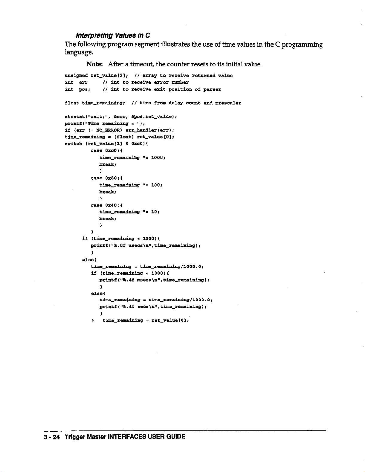
Interpreting Values in C
Interpreting Values in QuickBASIC and VisualBASIC
Interpreting Values in TurboPascal and
TurboPascal for Windows
The Request Set
ARM
CONT
FLAG
LOOP
STATUS
TRIG
WAIT
3-l 1
3-11
3-l 1
3-12
3-12
3-13
3-13
3-14
3-14
3-15
3-15
3-15
3-l 6
3-16
3-16
3-17
3-17
3-18
3-19
3-19
3-19
3-19
3-20
3-20
3-20
3-21
3-21
3-22
3-24
3-25
3-26
3-27
3-27
3-27
3-28
3-28
3-29
3-30
3-31
-6-
Page 7

3.7
3.8
CHAPTER 4 - PROGRAMMING EXAMPLES
STCLOAD
Calling STCLOAD from BASICA
Calling STCLOAD from C
Calling STCLOAD from QuickBASIC and VisualBASIC
Calling STCLOAD from TurboPascal and
TurboPascal for Window
STCDUMP
Calling STCDUMP from BASICA
Calling STCDUMP from C
Calling STCDUMP from QuickBASIC and VisualBASIC
Calling STCDUMP from TurboPascal and
TurboPascal for Window
3-31
3-31 3-31
3-32
3-32
3-32
3-32
3-33
3-33
3-33
4.1
4.2 BASICA Language Example
4.3 C Language Example
4.4 QuickBASIC Example
4.5
CHAPTER 5 - CREATING PROGRAMS FOR Trigger Master MEMORY
5.1
CHAPTER 6 - CREATING A BACKGROUND DATA ACQUlSllION SYSTEM
FORDOS
6.1
6.2
6.3
6.4
6.5
Introduction
TurboPascal Example
Introduction 5-1
Introduction
The TSR Structure 6-2
NOKPC488 and MISSINGGPIBDEV 6-3
STCRUN
WAITONSTC and JMPWAITSTC 6-5
WAITONGPIB and WAITONAUX 6-5
STCFLAG 6-5
STCLOG 6-6
STCEXIT 6-6
A TSR Log 6-7
A TSR Example 6-8
Creating a TSR for C
4-1
4-2
4-7
4-11
4-15
6-1
6-4
6-11
- 7.
Page 8

Contents
APPENDIXES
Appendix A - Trigger Master ERROR MESSAGES
Appendix 6 - COMMAND QUICK START
B.l
8.2
8.3
0.4
8.5
B.6
B.7
8.6
B.9
B.10
Appendix C -
C.1
c.2
c.3
c.4
C.5
C.6
c.7
Generate Trigger Outputs
Waft For Trigger Inputs
Enter Program Mode
Set Up and Terminate Program Loop (Program Mode Only)
Generate a Wait (Program Mode Only)
Track Program Execution and Generate interrupts
Exit Program Mode
lnftiate Program Execution
Halt Trigger Master Execution
Continue Execution of Halted Program
REQUEST QUICK START
Check Remaining Trigger Inputs Established by
ARM Command
Check Remaining Trigger Outputs Established by TRIG Command
Check the Actual State of the Trigger Lines
Check Time Remaining Before Next Trigger
Check Program Progress
Check Remaining Loop Count
Check Remaining Delay Time
B-1
B-l
B-2
B-2
0-2
B-2
B-3
B-3
B-3
B-3
C-l
C-l
C-l
C-l
c-2
c-2
c-2
-.s-
Page 9

1.1 GENERAL DESCRIPTION
Trigger Masterm is a system trigger controller for instruments and data acquisition
boards with external triggering. Trigger Master supports a variety of trigger functions
occurring in data acquisition systems. Trigger Master monitors trigger inputs, creates
delays, and generates trigger outputs.
An outstanding feature of Trigger Master is its ability to run programs from its own
memory and to generate interrupts at appropriate steps of program execution. This
allows Trigger Master, with
autonomous data acquisition system in your personal computer (PC) while you use
your PC for other purposes,
Trigger Master is implemented on two boards:
some
Chapter 1
INTRODUCTION
adjunct data acquisition hardware, to operate as an
. The KPC-TM board provides Trigger Master as a stand-alone plug-in board for the
PCru/XTn’/ATn”’ computer.
. The KPC488.2TM board combines Trigger Master with the high performance
KPC488.2AT GPIB interface to provide a standard interface with GPIB instruments.
Note: This manual describes Trigger Master. For information on the IEEE-488
functions, refer to the manual IEEE 488 Interface Boards which accompanies the
KPC488.2TM board.
Figure l-1 is a block diagram of Trigger Master.
Physically, Trigger Master is equipped with an 8-pin MicroDIN connector which has 6
trigger lines and 2 ground lines. In addition to Trigger-Linkn’ introduced later in this
chapter, the MicroDIN can connect directly to standard BNC connectors using the 8502
Trigger-Link Adapter.
Chapter 2 describes configuring and installtng the boards.
Trigger Master employs proprietary chips containing state machines that run from an 8-
MHz clock. This allows Trigger Master to respond to a change of trigger inputs by
generating a trigger output within 1.25 us. The state machine coordinates all functions
including the interfaces to Trigger-Link and the PC bus.
A PC program controls Trigger Master using 11 SCPI-like commands which a driver
transforms to microcode instructions, sending them to Trigger Master. Trigger Master
supports three modes of operation:
INTRODUCTION l-1
Page 10

Figure
.
l-1
Trigger Master Block Diagram
One mode of operation, Immediate Mode, allows some commands to be executed
immediately by Trigger Master.
. The second mode of operation, Progrum Mode, allows Trigger Master to store
commands in a 1-Kbyte program RAM as they are received for later execution.
Storing the program into RAM provides extremely powerful performance, since the
state machine can perform two level looping (one nested loop); for repeated
operations, the state machine uses available counters. This mode allows you to start
program storage and execution at any memory location, therefore allowing several
small programs to be resident in memory and allowing you to start them as
required.
. The third mode of operation, Run Mode, occurs while the Trigger Master executes a
program.
A user can generate trigger programs using any of the following methods:
Pass command strings from the user program to the Trigger Master driver.
.
. Write trigger programs using an ASCII-output word processor and then compile the
programs with STCCOMP.EXE.
Program interactively using PLAYWIN.EXE and PLAYDOSEXE, running,
.
respectively, from the Windows and DOS environments.
Any word processor that provides ASCII output allows you to write Trigger Master
programs, store them in ASCII, and then “compile” the output using the STCCOMP.EXE
program. Chapter 6 describes this procedure. The resulting “object” file is then easily
loaded into Trigger Master program memory and executed.
1 - 2 Trigger Master INTERFACES USER GUIDE
Page 11

The Trigger Master driver supports up to four boards simultaneously. The driver
accepts the following commands:
ARM
Set trigger input condition and wait for trigger
BEGIN Enter program mode
CONT Restart a halted program at the next step
DO Mark the start of a program sequence that is to be performed as a loop
END
Mark the end of a program mode sequence with a HALT and return to
immediate mode
FLAG Write a value to a diagnostic flag register (to trace program execution)
HALT Halt Trigger Master operation
LOOP Mark the end of a program loop
TRIG Generate triggers
WALT Cause a program to execute a time delay
X Begin program execution
The program STCRUNCOBJ, described in Chapter 6, builds terminate-and-stay-resident
programs (TsRs) for programs written in C. These programs are driven by interrupts
generated by
the
Trigger Master; the programs can run in the background in a DOS
environment while you run other programs from DOS.
Chapter 3 describes the PLAYDOSEXE and PLAYWIN.EXE programs which allow you
to become familiar with the commands and requests, test your hardware without doing
any programming, and generate Trigger Master programs for future execution.
PLAYDOSEXE
runs in the DOS environment, while
PLAYWINEXE executes from
Windows. Refer to Appendix B for a quick start on the commands and Chapter 3 for a
detailed description of the commands.
In addition to sending commands to Trigger Master you can also request information
from Trigger Master. Trigger Master supports the following requests:
ARM
CONT
FLAG
LOOP
Return information about the trigger detect circuitry
Return the current Trigger Master program position
Read the value from the diagnostic flag register
Return the execution status of a Trigger Master program loop
STATUS Return the value from the Trigger Master status register
TRIG
WAIT
Return information about the trigger output circuitry
Return the remaining delay time
Refer to Appendix C for a quick start on the requests and see Chapter 3 for a detailed
description of the requests. Chapter 4 provides programming examples of the
commands and requests in the supported languages.
INTRODUCTION l-3
Page 12

1.2 DISTRIBUTION SOFIWARE
This manual refers to Trigger Master software as the Di.dribution Software. The
Distribution Software contains utility files and driver files. Chapter 3 discusses these
1.3 SPEClFlCATlONS
Channels:
Basic Functions:
Micro Sequencer:
Modes:
Looping:
Loop Repeat:
Trigger Repeat:
Sequencer RAM:
Time Base Drift:
Trigger Input Pulse Width:
Trigger Output Pulse Width:
Detection Latency:
Async Trigger Latency:
Programmable Delay:
Trigger Connector:
Modes:
Power Consumption:
6 Input/Output
Trigger Detection
Trigger Generation
Delay Generation
PC Interrupts
Program, Immediate, or Run
2 Levels
1 - 4096
l-4096
1024 bytes
100 ppm max
4OOnsmin
5us
900 ns max
2.2 us max (trigger in to trigger out)
Range Resolution
1 us to 65.536 ms
10 us to 655.36 ms
100 us to 6.5546 set
1 ms to 65.536 set
1 us
1ous
100 us
1 ms
&pin microDIN
Sync, semi-sync (Trigger-Link), async
KPC-TM:
KPC488.2T2TM:
450 mA @5V max
1650 mA @5V max
Environmental:
Operating Temperature:
Storage Temperature:
Humidity:
oto+70c
-25 to +85 C
0 to 95%, non-condensing
Dimensions:
KPC-TM:
KPC488.2TM:
4.25 in H x 5.0 in. W (half-slot)
4.25 in. H x 13.25 in. W (ii.ilI slot)
Software:
Call Driver Languages:
Trigger Master DLL:
1 - 4 Trlgger Master INTERFACES USER GUIDE
BASICTM, QuickBASIC, C, Turbol’ascalsr’,
VisualBASIC for DOS.
Operation with Windows 3.x languages. Includes
VisualBASIC, Borland C++, C for Windows, and
TurboPascal.
Page 13

1.4
Trigger-Link
Trigger Master supports Trigger-Liim,
accuracy, and throughput to test and instrumentation systems. This section introduces
the features of Trigger-Link
You can easily change the trigger paths between instruments using Trigger-Link with
GPIB commands. The precise trigger signals on Trigger-Link enhance the accuracy and
throughput of the system. Even systems which contain lnsbuments without Trlgger-
Link can benefit by using the 8502 Trigger-Link Adapter. The 8502 Trigger-Link Adapter
is the interface to Trigger-Link for conventional BNC trigger connections. Figure l-2
illustrates various Trigger-Link configurations.
Mechanically, Trigger-Link consists of a cable with six signal paths and two grounds
which can be permanently daisy-chained between a group of instruments. The signal
paths convey trigger signals between instruments. With GPIB commands, instruments
can be configured to use one or more of the signal paths in a variety of modes. Thus the
trigger configuration of a group of instruments can be easily altered by software to suit
the requirements of a particular test.
ElectricalIy, Trigger-Link provides paths for trigger pulses between instruments, thus
eliminating the late&es involved with coordinating trigger functions with the GPIB
interface. This greatly increases system throughput and measurement preciseness for all
instrument systems. Instruments, which completely embrace the Trigger-Link standard,
employ a fast-track link between the trigger input and function execution and between
function conclusion and acknowledge output. Today, many instruments service the
trigger/acknowledge connectors periodically using a microprocessor that performs
other functions. However, this procedure results in unknown and variable timing
latencles as well as slower response.
which brings a new dimension of flexibility,
Trigger-Link supports three trigger modes:
SYNC MODE A source sends a trigger pulse or sequence of pulses to synchronize
the activities of one or more receivers. There is no acknowledgement
from the receiver(s) that they have received a pulse and are
responding properly to the trigger(s).
ASYNC MODE
The conventional two-wire handshake protocol where triggers are
sent on one line and the receiver acknowledges on a second line.
Conceivably, multiple instruments could share a common trigger
source, but each instrument would require a separate
acknowledgement line.
SEMI-SYNC
An innovative extension of the async mode which allows a single
trigger source and multiple receivers to carry out a handshake on a
single line. The trigger source will pulse the trigger line to an active
state for about 5 us. Upon receipt of the bigger all receivers wlIl hold
the trigger line in the active state before the trigger source goes
inactive. Each individual receiver will continue to hold the line active
until that receiver is ready to acknowledge it has completed its task.
When the line goes inactive the trigger source will know that all
receivers have completed their tasks.
INTRODUCTION ‘I - 5
Page 14

Figure l-2
I- 6 Trigger Master INTERFACES USER GUIDE
Trigger-Link Configuration Examples
Page 15

Chapter 2
INSTALLING Trigger Master
2.1
INTFlODUCTlON
The installation of Trigger Master includes the following:
. inspecting the KPC-TM and KPC488.2TM boards.
. setting jumpers and switches on
. inserting the two boards into your PC.
attaching all cables to the boards.
.
. running the PLAYDOS.EXE and PLAYWINEXE programs to exercise and verify
proper operation of the boards.
2.2 INSPECTING THE BOARDS
Remove each board from their protective packaging by grasping the metal rear panel
and removing the board from the anti-static bubble package.
Note: You
should handle the boards only by their edges. A static electric
discharge can damage
the
KPC-TM and KPC488.2TM boards.
the
integrated circuits on the boards.
INSTALLING Trigger Master 2 - 1
Page 16

2.3 SETTING UP THE KPC-TM BOARD
The KPC-TM board is a stand-alone system trigger controller which requires four byte-
wide I/O addresses. The board contains a switch to set up the base address in
increments of four bytes. This switch decodes address lines A9 to A2. The KPC-TM
board ships with a default setting of 3lO(hexadecimal) as
position OFF corresponds to a logical 1 and the position ON to a logical 0. Table 2-1 lists
the base addresses with the appropriate switch settings for each address.
shown in
Figure 2-l. The
Figure 2-l
You can configure
changing the jumper
KPC-TM Card Jumper and Switch Locations.
the
KPC-TM board to generate interrupts
on
jumper block J2. Trigger Master ships with the interrupts
on levels 2
through 7 by
disabled as shown in Figure 2-1.
Note: The KPC-TM Base Address switch settings are position values only. Refer to
Table 2-1 for the corresponding Address Line values.
Address
Decimal Hexadecimal
512
256
128
64
32
16
a a
4
200
100
80
40
20
10
4
&&e
9
a
7
6 4
5
4 6
3
2
Switch
m
1
2
3
5
7
a
Table 2-l
2 - 2 Trigger Master INTERFACES USER GUIDE
Base Address Switch Setdngs
Page 17

2.4
SElllNG UP THE KPC488.2Thl BOARD
The KPC488.2TM board implements the trigger master control function and GPIB
control function on the same board. Both the trigger master and GPIEi functions can
generate interrupts. This manual describes the settings for the interrupt Jumpers and the
switch and jumper settings for the GPIB function. Refer to the accompanying user
manual, IEEE 488 Interface Boards, for further information. Figure 2-2 shows the locations
of the jumpers and switches on the KPC488.2Th4 card.
2-2 KPC-488.2TIM Card Jumper and Switch Locations
To prevent the same level from being used by both functions, use the interrupt three-
row jumper blocks to select the interrupt.
Use Jumper blocks J5 and J3, shown in Figures
3-2 and 3-3, to set the interrupts levels for the
GPIB and Trigger Master. The top and middle
rows of the jumper blocks set the GPIB
interrupt level, and the bottom and middle
rows set the Trigger Master level.
. Placing a lumper vertically on the upper
and middle rows enables an interrupt level
for the GPIB. Placing a jumper vertically
the middle and bottom rows enables an
interrupt level for Trigger Master.
. Placing the GPIB jumper horizontally on
the upper row disables the GPIB interrupt and placing the trigger master jumper
horizontally on the bottom row disables the bigger master interrupt.
Figure 2-3 illustrates enabling interrupt level 12 for the GPIB and enabling interrupt
level 15 for Trigger Master (note that level 13 is unavailable on the PC/AT bus).
on
F
3gurfs
r
%ampfe
29 Jumper Blocks J5 and J
INSTALLING Trigger Master
2 - 3
Page 18

Trigger Master requires four byte-wide addresses; use switch SW3 to set the base
address in increments of 4. The switch decodes address lines A9 through A2. The
position OFF corresponds to a logical 1 and the position ON to a logical 0. The boards
ship with a default setting of 3lO(hexadecimal) as shown in Figure 2-2.
2.5 INSTALLING Trigger Master
Follow this procedure to install Trigger Master into your PC.
1. Turn the PC power switch to OFF. Unplug the power cord and disconnect all cables
from the rear of the system unit.
2. Remove the cover mounting screws from the rear of the system unit.
3. Slide the system unit cover forward. When the cover can go no further, tilt it up and
remove it from the base.
Note:
Install the KPC488.2TM board into a 16-bit slot; the KPC-TM board can
use an S-bit slot.
4. Remove the rear panel cover screw from one of the computers add-on slots.
5.
Press the board firmly into the main board expansion slot.
6. Seat Trigger Master cable in the Micro-DIN connector and align the board before
tightening the rear panel mounting screw.
7. Secure the board with the rear panel mounting screw.
8. Align the rear cover, sliding it back into place. Reinstall the mounting screws.
9.
Turn on the PC.
10. Make a backup of all application diskettes before copying the applications to your
PC’s hard disk.
11. Run the PLAYDOSEXE and PLAYWIN.EXE programs to exercise the boards.
Since the Trigger Master cable should seat completely in the MICRO DIN connector, you
may want to insert the cable and test the alignment of the card before tightening the
screw holding the bracket.
2.6 RUNNING PLAYDOSEXE or PLAYYVINEXE
Check the hardware and exercise Trigger Master after installation by running either the
PLAYDOSEXE or PLAYWIN.EXE program. PLAYDOSEXE runs from the DOS
environment and PLAYWIN.EXE executes in the Windows environment.
PLAYDOSEXE and PLAYWIN.EXE provide a menu interface to the standard Trigger
Master driver calls without requiring the use of a programming language. You can also
use these programs to create and document Trigger Master programs.
2
- 4 Trigger Master INTERFACES USER GUIDE
Page 19

The driver supports the following calls, which are described in detail in Chapter 3:
STCCMD Sends Trigger Master commands to the active Trigger Master
either for immediate execution or storage in Trigger Master
program memory.
STCDUMP Saves the contents of the active Trigger Master program memory
to a binary file.
STCINIT Checks for the presence of a Trigger Master. If Trigger Master is
found, it is initialized and made active. The driver can
simultaneously control up to four boards in the same computer.
STCLOAD Loads the contents of a binary file into Trigger Master program
memory.
STCSET
Selects a different Trigger Master to become active (this Trigger
Master must have been initialized).
STCSTAT Requests status information from the active Trigger Master.
The PLAYDOSEXE and PLAYWIN.EXE programs operate by listing these calls in a
main menu. When you select a call from the main menu, a form appropriate to that call
appears. Windows or buttons are provided, where necessary, for entering data or
making selections specific to that call. After l3ling in any blanks on the form, press the
button for the call to start execution. Any error messages retumed
from
the driver are
displayed.
Each form contains a “Help” button that provides assistance on that form. Context-
sensitive help is also available. To enable context-sensitive help, you must first include
the files PLAYWIN.HLP or PLAYDOSHLP in the same directory as the executible files
PLAYWIN.EXE or PLAYDOSEXE. Access help by pressing cFl> in PLAYWIN.EXE or
Shift+<Flz from PLAYDOSEXE.
If you select the STCCMD co mmand
from the main menu, a new menu appears listing
all the possible commands you may include with STCCMD. When you select a
command, another form appears that is specific to the that command. When you push
the STCCMD button, a window displays the comman
d string sent to the driver. The
“Man” selection is an option that allows you to manually.enter your own command
string (the string can contain multiple commands). If an error occurs during execution of
the STCCMD command, the driver displays an error message and places the value “**”
into your command string at the point the driver detected the error.
The “Man” form has a button that enables the “Paste” option. With this option
commands sent without errors from other command forms will also appear in
on,
the
“Man”
form command window. This procedure allows you to document a Trigger Master
program as you create it. You can save the contents Trigger Master memory with the
STCDUMP command. Since the STCDUMP co
mmand creates a non-readable
binary file,
you can use the “paste” provision to save the contents of the command window to obtain
a file of the command sequence used to generate the program.
When you execute the STCSTAT command, the command normally returns the status
only once. When you make a status request from PLAYWIN.EXE or PLAYDOSEXE, a
form is created which continually reads and displays the status. This procedure allows
you to follow the status changes as Trigger Master executes a program or command.
INSTALLING Trigger Master 2 - 5
Page 20

You can also watch the CONT STATUS request during program creation to determine
where the next program instruction will be loaded in memory.
The PLAYDOSEXE and PLAYWIN.EXE programs provide two methods of choosing a
different call or command and exiting a form:
Choose a new form without closing the current form. When you bring the current
.
form back up, the data you previously entered is still in the form. This procedure
simplifies the manual entry of commands, since you can recall the previous ten
commands by using the arrow keys at the side of the
entry
window. You can also
size and position forms to suit your needs.
. Click on the upper-lefthand button and choose the close option from the menu
displayed. When you next bring up the form, the data is reinitialized. To exit the
program, close the main menu (this automatically closes all forms).
2 - 6 Trlgger Master INTERFACES~USER GUIDE
Page 21

Chapter 3
USING THE Trigger Master DRIVER
3.1
INTRODUCTION
The Trigger Master driver supports the following languages: BASICA, Microsofto’
QuickBASIC, VisualBASIC (for DOS and Windows), Microsof@ C, C++, and C for
Windows, and Borlando’ TurboPascal and TurboPascal for Windows.
. For Windows applications, a Trigger Master DLL is placed in your Windows
directory.
. For DOS environment applications in QuickBASIC, VisualBASIC, C, and
TurboPascal, a Trigger Master file is linked with the application program.
.
For BASICA, a Trigger Master binary file is loaded with the program.
For maximum efficiency with all languages, the application program makes a direct call
to the appropriate driver code using the following calls-z
STCINIT
STCSET
STCCMD Sends co mmands to Trigger Master.
Checks for and initializes a Trigger Master at a specified board
address and then sets the driver to control that board. The driver
can simultaneously control up to four boards.
Switches Trigger Master control to a different board. The board
must have been initialized.
STCSTAT
STCLOAD Loads a binary flle into Trigger Master program memory.
STCDUMP Saves Trigger Master program memory to a binary file.
Requests status from Trigger Master.
3.2 USING THE DRIVER
The following sections describe “instalhng” the driver in each of the supported
languages.
Using the Driver with SASICA
Run the following code segment to load the driver In BASICA:
260 CLBhR , 52-1024
270 DBP sxo = 0
’ leave a045 for interface.
USING THE Trigger Master DRIVER 3 - 1
Page 22

Accessing the Driver from C
For Microsoft@’ C, compile your program and link the resulting object file with stcc.Zib
using a command such as the following:
You will need to include at least the function prototypes from stc.h in your program.
Note:
For C or C++ programs running under Windows, do
not link the
program to stcc.Zib. Instead, copy the file sfcIib.dll to your Windows
directory; the function prototypes in stcZib.dZl are identical to those in stc.h.
Accessing the Driver from QuickBASIC and VisualBASIC
QuickBASIC
Use one of the following methods when building an executable program from the DOS
prompt:
. If you use Version 4 or greater or Version 7 with near strings, link your program to
stcqb.lib.
. If you use Version 7 with far strings (compiled with /Fs), link your program to
stcqbzlib.
To run your program in the appropriate QuickBASIC environment, load the program
with one of the following files:
For Version 7, use the file stcqb7.qlb.
.
For Version 4.0 to version 7, use the file stcqb4.qlb.
.
In either case, you must include at least the function protocols from the file stcqb.bi in
your program.
3 - 2 Trigger Master INTERFACES USER GUIDE
Page 23

VisualBASIC
Place VisualBASIC function declarations in the Global section.
. For DOS applications:
To run a program from the environment, use the command VBDOS
/LSTCVED.QLB to load
VisualBASIC
with the Quick Library STCVBD.QLB.
Include function prototypes for the Trigger Master calls by incorporating the
Trigger Master include files with the statement ‘INCLUDE stcvbd.bi. The file
STCVBD.BI also includes error code definitions and an array to hold error
message strings. If you do not need to display error messages, delete the array;
otherwise, use the code in STCVBDLBAS to initialize the srray. You can build an
executable file
from
the environment or from the co mmand line. To build the file
from the command line, first compile each form or BASIC module of your project
using the command line compiler. Then, from the command line, link the
resulting object modules with the Trigger Master VisualBASIC for DOS library
STCVBDJJB to produce the executable file. The following command line
example illustrates the production of the file EXVBDMAK:
Be axvBD.Pm
BC sxvsD.aAs
LIta sxvm BxvBDI,,,STcvBP.LIB;
. For Windows applications:
Copy the file STCUB.DLL to your Widows directory. You will need to include function
prototypes for the Trigger Master calls in your global data The file STCVBWJXT
includes function declarations appropriate for the Global section of a VisualBASIC for
Windows application. This file also defines error codes and an error array. If you wish to
use the error array, you must include code from STCVBHXT in the load procedure of
your first form. The diffarence between the STCVBWXXT file and the DOS program file
STCVBDJXT is in the function declarations which are appropriate to STCLJB.DU.
Accessing the Driver from TurboPascal
Access the driver from a TurboPascal program (version 6) by including the following
statements in your program.
Far TurboPascal for Windows, copy the file STCLIB.DLL to your Windows directory
and include the folIowing statement in your program.
The include files contain function prototypes for the calls and define error codes. If you
want to display error messages, include an array for error strings. The file STCTPIPAS
contains code that you can add to your program to initialize the error array.
USING THE Trigger Master DRIVER 3 - 3
Page 24

3.3 STClNll
STCINIT checks for the presence of a board by writing to Trigger Master program
memory. STCINIT initially writes the value 0 and then increments this value through
255fdecimal). As the memory register is written, Trigger Master automatically
increments the on-board memory location so successive memory locations are loaded
with increasing values until reaching 255. At this point, STCINIT resets to 0 and repeats
the process until it writes to ail 1024 memory locations.
STCINIT then reads back the values. The process of reading the values automatically
increments the memory location.
cleared and STCINIT returns with no error.
If
the read
value
matches the write
value,
memory
is
If the board is present, it becomes “active” so that all subsequent cornman
ds or requests
to the driver will be sent to that board. Up to four boards can be initialized; as each
board is initialized, it becomes the “active” board. To reactivate an initialized board, use
the STCSET caIl.
Note:
Every time you run a program, you must initialize Trigger Master by
calling STCINIT before making any other calls. During initialization, only
Trigger Master program memory is deared; other registers may retain
values
from previous program execution.
STCINIT requires three arguments as follows:
STC~I'E~il9b,al%,i2%)
The variables definitions and ranges are as follows:
Variable Definition Ranae
il% (integer) Trigger Master reference number
al% Trigger Master board address
i2% (integer)
Indicates success of call
(refer to Appendix A for Trigger Master error messages.)
o-3
0-7FC
0 = suooessful
non0 = unsuccessful
Calling STCINIT from BASICA
Use the following BASICA code
segment
30fhex):
630 PRnm "mitialize board "2 m!mmm; *I It. address "i
610 PRINT Rsxs mmADDR%) t I' her"
650 ORLL STCIWITmsmmd%, RzamDDR%, -1
660 LF RMNON% THPN GOT0 2130
Note:
You must define ail arguments for the STCINIT call (BRDNUM%,
BRDADDR%, ERRNUM%) before making the call
3 - 4 Trigger Master INTERFACES USER GUIDE
to initialize a Trigger Master at address
Page 25

Calling STClNlT from C
Use the following code segment to initialize Trigger Master in C:
In C you can send values to the driver by placing them directly in the call. For example,
you could use the following code:
stchit(0,
0x300, ierr);
Since the driver returns err, you must have a predeflned variable to receive its value.
Calling STUN/T from QuickBASE and VisualBASIC
Use the following code to call STCINIT from QuickBASIC and VisuaIBASE
DIN .rerr As INTBOBR
DIM B.rcLNum As INmaR
DIMbdAddr AsIwmeER
s-=0
brdMdr ii &a310
PaIm "Ildtialie.3 board "IBrdaumi" at address "i
PRX”‘,’ BgX$tbrdiuWrl; ” hex”
In QuickBASIC and VisualBASIC, you can send values to the driver by placing them
directly in the call. For example, you could use the following code:
CALL s+cinie(o. LH310, *err1
Since the driver rehms
rerr, you must have a predeflned variable to receive its value.
Calling STCINIT from TurboPascal and TurboPascal for Windows
The following code illustrates calling STCINIT from a TurboPascal or TurboPascal for
Windows program:
stcinir(1.$314,err~;
USING THE Trigger Master DRIVER 3 - 5
Page 26

3.4
STCSET
Use STCSET in multiboard systems to switch the driver from one board to another. The
boards must have been previously initialized with the STCINIT command (described in
the
previous section). STCSET accepts two arguments as follows:
The argument il% is an integer in the range of 0 through 3 that identifies the
board.
The argument i2.% is an integer that receives an error code. A value of 0 indicates
no error (refer to Appendix A for a list of error messages).
3.6 Trigger Master INTERFACES USER GUIDE
Page 27

Calling STCSET from QuickBASIC and VisualBASIC
The following code segment illustrates calling STCSET in QuickBasic and VisualBASIC.
BdM.UUEO
Calling STCSET from TurboPascal and TurboPascal for Windows
The following code illustrates calling STCSET from a TurboPascal or TurboPascal for
Windows program.
stcsetIl,*rr) i
3.5 STCCMD
STCCMD sends commands to a board. STCCh4D accepts three arguments as follows:
01 refers to a string that contains a command to be translated by the driver into
microcode. The translated microcode is then sent to Trigger Master either for execution
by the on-board state machine or for storage in the Trigger Master memory. The,driver
parses the command, checking for unknown commands, invalid syntax, or values out of
range.
ix% is an integer that receives an error code. The driver returns a value indicating the
sIatus of errors: a value of 0 indicates no errors; refer to Appendix A for a list of error
messages.
ia is an integer that receives the position of the last character the driver parsed. Since the
driver stops parsing the command line when it encounters an error, this value provides
assistance for ermr debugging.
Note: Trigger Master executes commands as they are parsed. IfTrigger Master
discovers an error in a multiple-command string, it executes the commands prior
to the error and then returns with an emlr code.
Refer to Appendix B for a quick introduction to the commands using examples. Run
PLAYDOS.EXB or PLAYWIN.EXB to experiment with the commands in a non-program
environment. See Appendix A for a description of the error messages.
USING THE Trigger Master DRIVER 3 - 7
Page 28

Command Syntax
This section describes the syntax for the string argument (cl) in the STCCMD call. The
STCCMD call supports the following commands: ARM, BEGIN, CONT, DO, END,
FLAG, HALT, LOOP, TRIG, WAIT, and X.
General Information
The following rules apply to ail STCCMD commands:
. Spell out the commands in their entirety (abbreviations are not supported).
.
Complete each command with a semicolon (;l.
. Use any combination of uppercase and lowercase letters wlthin strings (the driver is
insensitive to the case of characters).
. Do not use embedded spaces wlthin a command. For example, the command “be
gin;’ is illegal.
Some examples of legal and illegal strings are as follows:
IIlerral Legal
beg;
Begin;
begin b&N;
In the example “beg”, the driver returns the position 3 and the error 3 which correspond
to the “Incomplete Command” error. As soon as the driver encounters an error it returns
You can group multiple commands together using blank spaces (spaces, tabs, carriage
returns, and line feeds) to improve readability. The following examples are equivalent:
bWfi.Wd;
begin ;
begin:
end;
6JUd;
The driver executes multiple commands contained in a single string when it encounters
a semicolon.
In
the previous example, the driver executes the “begin” command when
the driver parses the “;11 following “begin”. As a result, the driver executes commands
one at a time. When the driver encounters an error, the previous commands have
already been executed.
3 - 8 Trigger Master INTERFACES USER GUIDE
Page 29

Line Numbers
The commands ARM and TRIG must be followed by one or more line numbers. The
line numbers indicate which of the six trigger lines are armed to look for trigger inputs
or will generate trigger outputs. When either command specifies multiple lines, the line
values must be separated by commas. The following examples illustrate legal and illegal
line values:
j&g@ gg&
trig 1, 5;
trig 1 5;
TRIG 6:
trig3,2,1;
Note: You may use the same number more than once in a command line. This
does not alter the operation and is not flagged as an error.
Extenslons
Certain commands accept extensions, which further define the command. You must
spell out the entire extension (abbreviations are not accepted) and each extension must
be preceded by a
colon.
The following example initiates Trigger Master program
execution with interrupts enabled:
For additional information on L, refer to the section “The Command Set”.
Commands can be followed by one or more integers. An integer cannot contain
embedded spaces, but the number may be separated from the command using one or
more spaces. The integers in the following example indicate the memory location where
program
storage
should start. The examples of legal and illegal command lines are:
&g& j&&
beginl23; begin 1 231
begin
133~
begin 123 ;
The driver checks the range of the number and returns an error if the value is out of
range.
USING THE Trigger Master DRIVER 3 - 9
Page 30

Time Scales
Two commands require time arguments: WAIT and TRIG. The WAIT command
generates time delays in a program running from Trigger Master memory (for further
information on both commands, refer to the section “The Command Set”). The WAIT
command syntax is:
%.a is a floating-point number that specifies a magnitude of time.
t indicates a time scale using one of the following three values:
sorS seconds
m or M milliseconds
n or U microseconds
The magnitude of limes (a.=) that can be used with the WAIT command range from 1
microsecond through 65.535 seconds. You can write time values using any choice of milts. For
example, the minimum and maximum times may be entered as any of the following values:
Minimum
lu
.OOl
m
0.000001 s
Maximum
65535000~
65535 m
65.535 s
The magnitude of the time between any leading and trallmg zeros must fit in a 16-bit
counter; therefore, the range is between 1 and 65535. This limits the so-called resolution
of the time scale (how fine a time increment you may specify). This allows the use of up
to five digits for 1 to 65535, but only four digits for 6554 to 9999. For example, the values
0.06553400 s and 0.06553500 s are legal, but the value 0.06553600 s is illegal. The driver
allows an increase of 0.00000100 s from the value 0.06553400 s to 0.06553500 s. If we
attempt to increment the same amount to get to 0.06553600 s, the driver returns the error
“TIME OVER RESOLUTION”. This requires a rounding up to the next higher value in
the digit to the left; in this example, the next larger value of time that can bespecified is
0.06554000 s. This value represents an increment of 0.00000500; the next incremental
value would be 0.00001000 (to 0.06555000 s).
3 - 10 Trigger Master INTERFACES USER GUIDE
Page 31

The time resolution depends on the time value as shown in the following table:
Delav Ranqe
0.000001 s to 0.065535 s 1 usec
0.065540 s to 0.65535 s
0.65540 s to 6.5535 s
6.5540 s to 65.635 s
Note:
If you attempt to enter the digits 65536, the driver returns the error “TIME
Resolution
10 usec
100 usec
1000 usec
OVER RBSOLUTION”. Unless your time scale is microseconds, you wlll
be over-range as well.
Sanding Commands in fbe Programmhg Languages
Commands are sent by calling STCCMD with the appropriate arguments. One of the
arguments is the string specifying the command. The general features of those strings
have been diicussed ln the previous section and the detailed use of each string will be
discussed in the following section. This
section shows the
use of the call in each of the
programming languages supported.
Calling STCCMD from BASICA
In BASICA, you must define all arguments before making the calI
Calling STCCMD from C
In C, you must declare unsigned variables to receive information from the driver.
However, the command string sent to the driver can be inserted directly in the call.
USING THE Trigger Master DRIVER
3 - 11
Page 32

Calling STCCMD from QuIckBASiC and VisualBASIC
In QuickBASIC and VisualBASIC you must declare integer variables to receive
information from the driver. However, the command string sent to the driver can be
inserted directly in the call.
begircme$ 5 “begin;” ’ begin pro*ram
DM rerr As Ib!mOBR
DIM POEa As *NmoaR
PRINT “Sand “i begincma$; ‘8 EOmfwad”
CALL
s+ccmd(beginamd$,
rerr, post)
IP r*rr <> WOWRROR 9!awN CALL Brrorzxit(rerr~
Calilng STCCMD from TurboPascal and TurboPascal for Wlndows
In TurboPascal and TurboPascal for Windows you must also declare unsigned variables
to receive information from the driver. However, the CO
mmand string sent to the driver
can be inserted directly in the call.
STCTPUB
string.
is a special interface to TurboPascal that accepts a standard TurboPascal
STCLIBDLL
is a general DLL that expects so-called “c” strings. To send strings to
the DLL in TurboPascal for Windows, create a string with a NULL character on the end
outside the call, and pass the “second element” of the string in the call.
3 - 12 Trigger Master INTSRFACES USER GUIDE
Page 33

The Command Set
The command set consists of ARM, BEGIN, CONT, DO, END, FLAG, HALT, LOOP,
TRIG, WAIT and X. The Trigger Master mode of operation determines how the
commands are operated on:
. In immediate mode, Trigger Master executes commands as they are received. The
commands BEGIN and CONT operate only in this mode.
. In program mode, the commands are stored in Trigger Master memory for future
execution. The commands DO, END, LOOP, and WAIT operate only in this mode.
. In run mode, Trigger Master is executing a program and will only recognize the
HALT command.
The remaining commands (ARM, FLAG, HALT, TRIG, and XI can be used in any mode
of operation.
The following sections discuss the commands in detail.
ARM
The Trigger Master trigger-detect logic latches trigger edges on the six trigger input lines
(the default is high-to-low transitions). The ARM command specifies a trigger input
transition pattern to be detected. When the ARM command executes in a Trigger Master
stored program, the program waits until the pattern is detected before proceeding to the
next program step. In immediate mode, you can loop using the TRIG request
(previously described) to detect the pattern.
The ARM command must be followed by one or more line numbers. If you enter
multiple line numbers, separate each number using commas. Specifying the same line
number more than once has no effect and is not flagged as an error. The following
example waits for high-to-low trigger transitions on lines 1 and 5.
-.si
You can specify the edge to latch by using a + (low-to-high) or - (high-to-low, the
default) behind the line number. The following example waits for a low-to-high
transition on line 1 and high-to-low transitions on lines 3 and 5.
ann I.+, a-, 5;
Note: Because of the latching
nature
of the detect circuit, the edges need not
occur simultaneously and the state of the trigger lines wlll generally
differ from the pattern specified in ARM when the trigger condition is
met.
In program mode, ARM supports the REP extension which allows you to wait for the
trigger pattern to be repeated from 1 to 4096 times before proceeding. The following
command line will wait for 23 repetitions of a trigger pattern of high-to-low transitions
on lines 1 and 4. Each time the pattern is detected, latches are automatically cleared and
rearmed.
USING THE Trigger Master DRIVER 3 - 13
Page 34

The general syntax for the ABM command is:
ARM flI+l-l 1....)[:Fsz nn1:
The variable r must be within the range 1 through 6 and the variable IYL must be in the range 1
through 4096.
BEGIN
Use BEGIN only in immediate mode to switch Trigger Master to program mode. The
BEGIN command optionally accepts a single argumenb the Trigger Master program
memory address where the program will start loading. This integer argument must be
in the range 0 through 1023 (the default starting address, with no argument, is 0). The
following example switches the driver to program mode and initializes the program
counter to 40.
begin 40;
The general syntax for the BEGIN command is:
The variable = must be in the range 0 through 1023.
Normally, you will start program loading and execution at address 0, but you may also have
multiple programs in memory (terminate each program with an
To
load or execute multiple programs, you must know the locations of the instructions.
Determine these locations either by building a program from
PLAYDOSJXE or by using the techniques described in Chapter 5, Creating
END
or HALT command).
PLAYWNEXE
or
Programs for
Trigger Master Memory.
CONT
Use CONT in immediate mode to restart a program that was stopped by a HALT
command
or FLAG[m]:INT
command within the program. You cannot reliably restart a
program that has been halted externally (from outside the program). If the program
contains additional FLAG[nn]:INT commands, use the CONT command with the INT
extension to clear the previous interrupt and arm Trigger Master to generate another
interrupt. The following example restarts a program without interrupts:
This example restarts a program executing out of Trigger Master memory. The general
syntax for the CONT command is:
ccmz Ir1NTl;
Note:
If you enable Trigger Master to generate interrupts, you must supply your own interrupt
service mutlnes.
3 - 14 Trigger Master INTERFACES USER GUIDE
Page 35

DO
Use DO in program mode to mark the start of a sequence of code which is to be
repeated. The DO command requires a single argument, which is an integer in the range
of 1 through 4096. The
argument
specifies the number of times the code sequence is to
repeat. The code sequence must be terminated by the LOOP command (described later
in this section). The driver allows two levels of loops; the driver will flag an error if you
attempt to start a third level. In the following example, first command1 executes, then
command2; this code sequence repeats 25 times:
de 25; cemmand1; c-i loop;
The general DO syntax is:
Do nni
nn is in the range 1 through 4096
END
Use END in program mode to insert a HALT (described later in this section) and return
Trigger Master to immediate mode. The driver wIII return an error if you attempt to end
a program that has DO commands which have not been resolved by a LOOP.
The general END syntax is:
FLAG
Use FLAG In program mode to insert FLAG
commands in a
program. As the program
executes, FLAG will write a byte to the flag register. The byte should be a value in the
range of 0 through 2.55 (0 is the default). You can then use the FLAG request to read the
flag register to determine which milestone your program
has
reached. If FLAG has the
INT extension in program mode, FLAG causes the Trigger Master program to generate
an interrupt and halt after wrltlng the flag. Use FLAG in immediate mode for test only;
this o~peratlon writes a byte ln the range of 0 through 255 (0 is the default) to the Trigger
Master flag register. For example, the following command writes 68 to the flag register:
The general syntax for the FLAG command is:
FLAG tno1 I:Qml:
The value nn is in the range of 0 through 255.
Use the extension :INT only in program mode.
Note:
If you enable Trigger Master to generate interrupts, you must supply your own
interrupt service routines.
USING THE Trigger Maeter DRIVER
3 - 15
Page 36

HALT
The HALT command stops Trigger Master activity, disables Trigger Master hardware
interrupts, and clears the hardware interrupt. When HALT executes during Trigger
Master program execution, you can use the CONT command to restart the program on
the next instruction. Use FLAG with the INT extension in a Trigger Master onboard
program to halt a program, write the flag register, and generate an interrupt.
The general syntax for the HALT command is:
LOOP
Use LOOP in program mode to terminate a loop Initiated with the DO command.
The general syntax for the LOOP command is:
Use TRIG to generate high-to-low trigger pulses (5 us active low). The TRIG command
accepts from 1 through 6 arguments with each argument specifying a line number.
Multiple line number arguments must be separated by commas. Repeating the same line
number more than
once has no effect
and does not flag an error. The following example
simultaneously generates 5-us pulses on lines 2 and 4.
You can generate a repetitive pulse train of 1 through 4096 pulses by using a REP
extension. If you use the REP extension, you must also use the PER extension with a
time; this time value specifies the REP period. The following TRIG example generates 72
~-US pulses on lines 2 and 3 with a repetition period of 16 milllseconds.
The maximum period you can specify is 65.535 seconds and the minimum period is 10
microseconds. Refer to the section Time Scales in this chapter for a complete discussion
on specifying times.
In program mode, you can use the SEMI extension alone, or in combination
with the
REP extension. The SEMI extension implements the semi-synchronous handshake. In
semi-synchronous handshake mode, Trigger Master initiates a 5-us active-low trigger
pulse on a line; handshaking devices then become active low within 5 us. To complete
the handshake, the devices release the line when they have completed their activity. The
handshake is complete when Trigger Master detects the low-to-high transition of the
line. In the semi-synchronous handshake mode, the TRIG command does not require the
PER extension.
The following example performs a semi-synchronous handshake on line 3.
trig S:sdr
Note: The SEMI extension is only valid in program mode.
The general syntax for the TRIG command is:
TRIO
Cl,...)
[ [rRBP pnt:PaR XT t,1mI,:SsbiI~Paa r‘r t>1 I [rsEMIl I;
The variables may contain the following values:
3 - 16 Trigger Master INTERFACES USER GUIDE
Page 37
Variable Definition
I
nn Trigger pattern repeat
rr Real value of time
t
Refer to the section Time S&es in this chapter for a complete discussion on
specifying times and the range of values.
Line number(s) l-6
time scale
I!@!x
1 - 4096
*
*
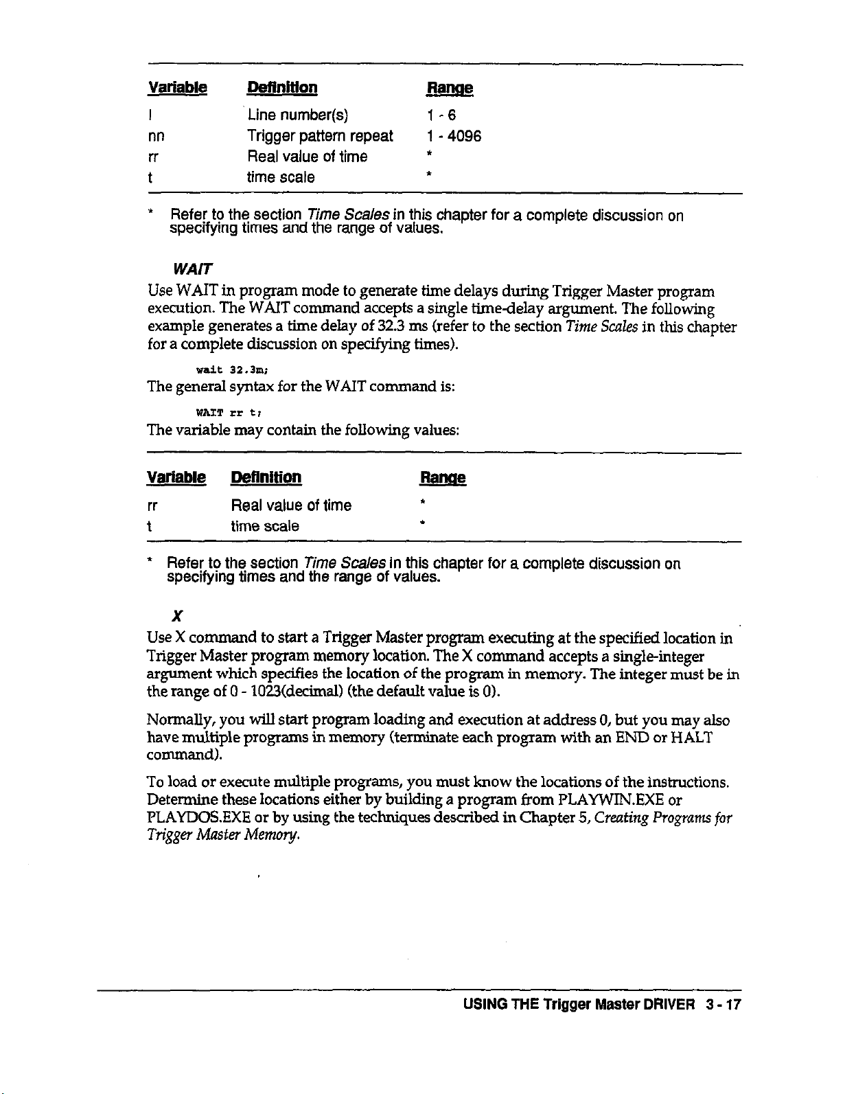
WAIT WAIT
Use WAIT in program mode to generate time delays during Trigger Master program Use WAIT in program mode to generate time delays during Trigger Master program
execution. The WAIT command accepts a single time-delay argument. The following execution. The WAIT command accepts a single time-delay argument. The following
example generates a time delay of 32.3 ms (refer to the section Time Scales in this chapter example generates a time delay of 32.3 ms (refer to the section Time Scales in this chapter
for a complete discussion on specifying times). for a complete discussion on specifying times).
wait 32.3m;
The general syntax for the WAIT command is:
mm ?x t;
The variable may contain the following values:
Variable Definition j?gJ@
rr Real value of time
t time scale
* Refer to the section
specifying times and the range of values.
X
Time
S&?/es in this chapter for a complete discussion on
*
*
Use X co mmand to start a Trigger Master program executing at the specified location in
Trigger Master program memory location. The X command accepts a single-integer
argument which specifies the
location
of the program in memory. The integer must be in
the range of 0 - 1023fdecimal) (the default value is 0).
Normally, you will start program loading and execution at address 0, but you may also
have multiple programs in memory (terminate each program with an END or HALT
command).
To load or execute multiple programs, you must know the locations of the instructions.
Determine these locations either by building a program from PLAYWIN.EXE or
PLAYDOSEXE or by using the techniques described in Chapter 5, Creating Programs for
Trigger Master Memory.
USING THE Trigger Master DRIVER
3 - 17
Page 38

Notes: If Trigger Master is operating in program mode, the driver inserts a
If your program contains a FLAG command with the INT extension, use the X command
with the INT extension to clear a previous interrupt and enable Trigger Master to
generate interrupts. The following example starts execution of a program at memory
location 178fdecimal):
x
178;
The general syntax for the X command is:
x Ino1 t:Iwr1r
The acceptable range for the variable nn is 0 through 1023fdecimal).
Note: If you enable Trigger Master to generate interrupts, you must supply your own
internrpt service routines.
3.6 STCSTAT
HALT at the current memory location. Trigger Master returns to
immediate mode prior to starting program execution.
In program mode, the driver returns an error if you attempt to end a
program containing DO commands that have not been resolved by a
LOOP command.
Use the STCSTAT command to return Trigger Master register values. STCSTAT accepts
four arguments in the following order:
Areument
1
2
Desaiution
A string specifying the Trigger Master register value to be returned.
An integer to receive the error code returned by the driver after
validating the request string.
3
An integer to receive the position of the last character parsed by the
driver. You can use this value to pinpoint problems lf the status
indicates an error.
4 An array of two integers to receive the data.
Appendix B provides a quick introduction to STCSTAT. The PLAYDOSEXE and
PLAYWIN.EXE programs allow you to experiment with requests in a non-programming
environment. Refer to Appendix A for a list of the possible error messages.
Note:
Once the Trigger Master driver has fllled
one
request, it immediately
returns. This is an opposite condition to commands, which perform
multiple requests before returning. Therefore, you should not place
multiple requests in the same string.
3 - 18 Trigger Master INTERFACES USER GUIDE
Page 39
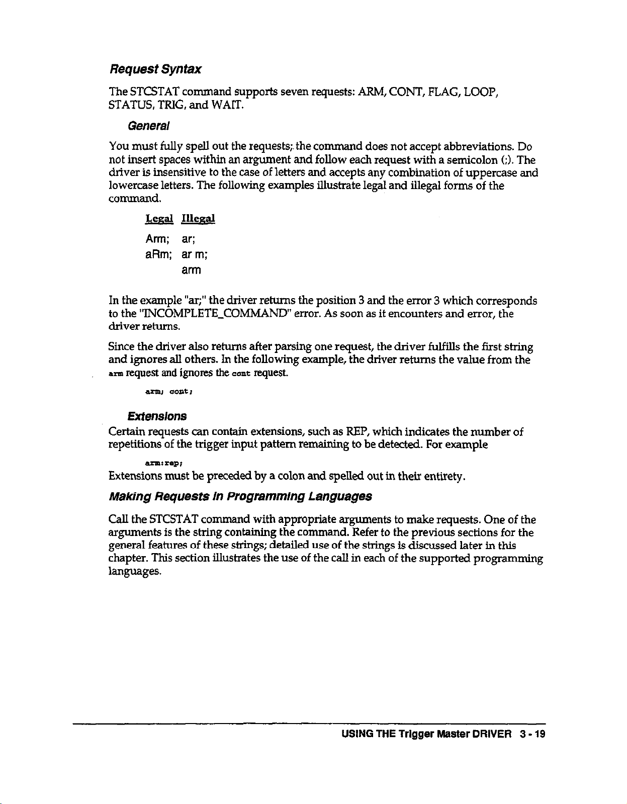
Request Syntax
The STCSTAT command supports seven requests: ARM, CONT, FLAG, LOOP,
STATUS, TRIG, and WAIT.
General
You must fully spell out the requests;. the comman
d does not accept abbreviations. Do
not insert spaces within an argument and follow each request with a semicolon (;). The
driver is insensitive to the case of letters and accepts any combination of uppercase and
lowercase letters. The following examples illustrate legal and illegal forms of the
command.
&al Illegal
Arm;
aRm; arm;
ar;
arm
In the example “ar;” the driver returns the position 3 and the error 3 which corresponds
to the ‘TNCOMPLETE-COMMAND” error. As soon as it encounters and error, the
driver returns.
Since the driver also returns after parsing one request, the driver fulfills the first string
and ignores all others. In the following example, the driver returns the value from the
-request and ignores the EO=~ request.
Extensions
Certain requests can contain extensions, such as REP, which indicates the number of
repetitions of the trigger input pattern remaining to be detected. For example
Extensions must be preceded by a colon and spelled out in their entirety.
Making Requests in Programming Languages
Call
the
STCSTAT command with appropriate arguments to
make
requests. One of the
arguments is the string containing the command. Refer to the previous sections for the
general features of these strings; detailed use of the strings is discussed later in this
chapter. This section illustrates the use of the call in each of the supported programming
languages.
USING THE Trigger Master DRIVER
3 - 19
Page 40
Calling STCSTAT from BASICA
The following segment illustrates calling STCSTAT from BASICA.
1490 '
1500 '*****f***=*** WAIT FOR DELAY
1510 ’
1510 INITS-Waiti”
1530 CALL slwmT’(INIT$, BRRMlld%, Las’EcHR%, iumJLT$(O))
1540 IF - TESN oow 2130
l tt.tt**f~**~~***~*~**~,~~**~*
Note: All variables used in the call must be defined before the call is made.
Calling STCSTAT from C
The following segment illustrates calling STCSTAT from the C programming language.
unsigned rat~“alue[2,> /I array to receive returnee value
int err; ,, ilIt to receive error nurber
int ws;
,/ int to reaeive exit pesition Of passer
sraseat(waiti”, &err, r*os,ree~“alue~;
if Ierr II tw~RRoR, erLhandle,r~err) ;
Note: AU values returned by the driver must be declared before the calls.
Calling STCSTAT from QuickBASIC
and VisualBASIC
The following segment W&rates calling STCSTAT from QuickBASIC and VisualBASIC.
DIM
Reval
As IuTmnR
DIM rerr As IwmOER
Dn4 pst As mTxt?ER
3 -
OPJJ, stCstat~“valti”, rerz1, past, astVal(Ol~
IF rer+ <> NOBBXOR mmi eALL ErrorEgxit kerr)
Note: All values returned by the driver must be declared before the calls.
20
Trigger Master INTERFACES USER GUIDE
Page 41
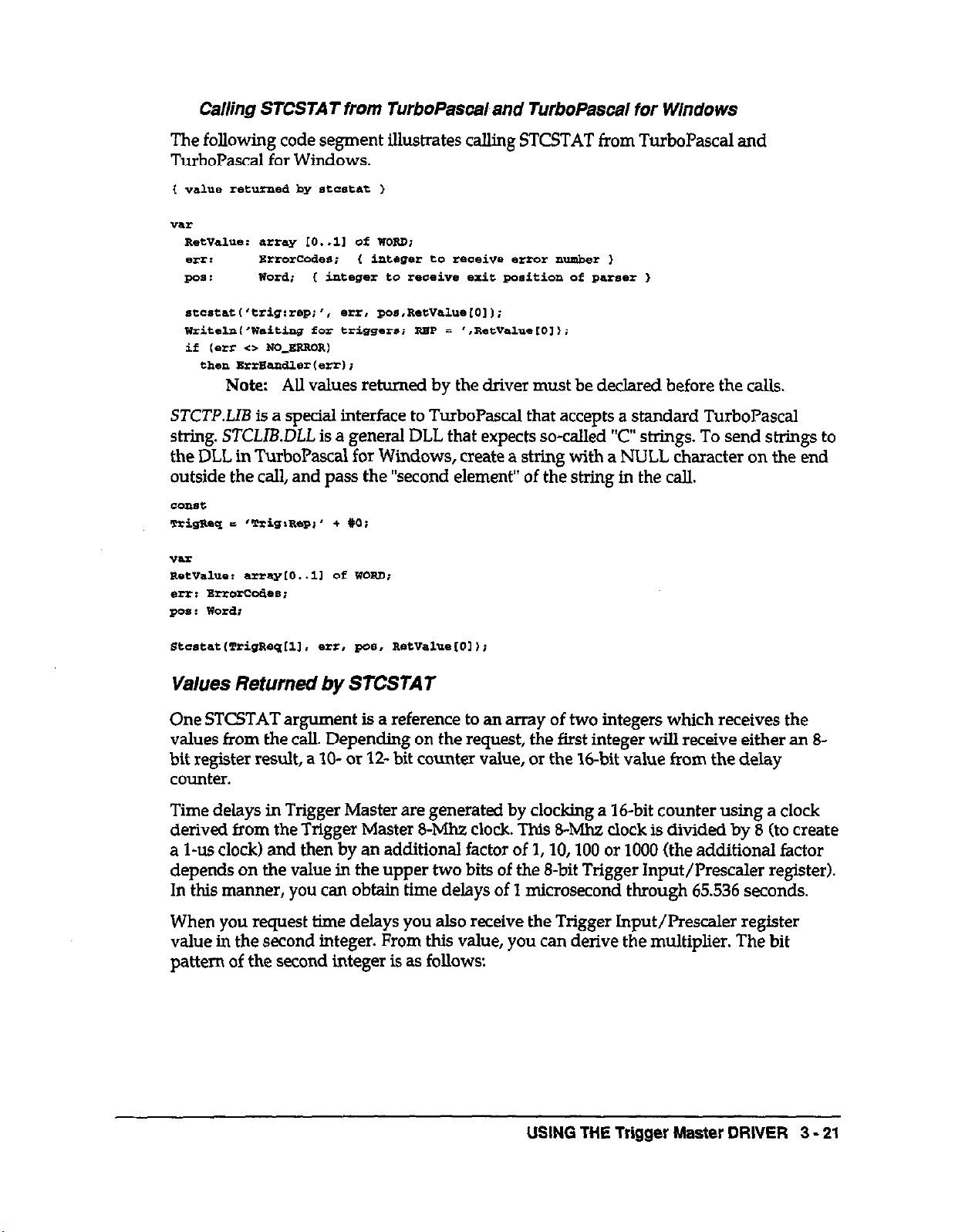
Calling STCSTAT from TurboPascal and TurboPascal for Windows
The following code segment U.&rates calling STCSTAT from TurboPascal and
TurboPascal for Windows.
R*t”a1Ye: array 10..11 ct WORD;
etlr: Errorcedes; C integer to receive error number )
pas: Word; t
stcrrtat('trig:rep;', er+, pas.Ret”01ue10,);
integer
to reaeiw exit **ition of p*rs*r I
w~ireln~‘waiting ioz triggers; RBP = ‘.Ret”alue~O,,;
if (err c> No_ERROR)
theri Earaadlerfen);
Note: All values returned by the driver must be declared before the calls.
STCTP.LIB is a special interface to TurboPascal
that
accepts a standard TurboPascal
string. STCLIB.DLL is a general DLL that expects so-called “c” strings. To send strings to
the DLL in TurboPascal for Windows, create a string with a NULL character on the end
outside the call, and pass the “second element” of the string in the call.
C-t
him-? =
‘TriS%R8Pi’ + Y0;
-?a?2
Retvalue: an~y~o..ll Of mm;
err: BrrOrccae*;
go*: wordt
Values Returned by STCSTAT
One STCSTAT argument is a reference to an array of two integers which receives the
values from the call. Depending on the request, the first integer will receive either an 8bit register result, a 10- or 12- bit counter value, or the %-bit value
from the
delay
counter.
Time delays in Trigger Master are generated by clocking a 16bit counter using a clock
derived from the Trigger Master 8-Mh7. clock. This 8-Mhz clock is divided by 8 (to create
a l-us clock) and then by an additional factor of 1, 10,100 or 1000 (the additional factor
depends on the value in the upper two bits of the 8-bit Trigger Input/Prescaler register).
In this manner, you can obtain time delays of 1 microsecond through 65.536 seconds.
When you request time delays you also receive the Trigger Input/Prescaler register
value in the second integer. From this value, you can derive the multiplier. The bit
pattern of the second integer is as follows:
USING THE
Trigger
Master DRIVER 3 - 21
Page 42

-3 *. .I
a m -0 , . 7 . I 1 3
2 , 0
0 0 0
0 0 0
0 OMIMOX
X X
X X X
Bits Ml and MO determine the time multiplier as follows:
m
0 0 1
0 1 10
1 0 100
1 I 1000
MO
Multiplier
When you request a time, you need only look at the second integer. The driver also uses
the second integer to return a code which is helpful in interpreting the result of the
operation. The following lists the various codes returned for different commands:
@&
FFFO
FFFl
FFF2
FFF3
FFF4
FFF5
FFOO
FFOl CONT;
FF02
FF03
Command
ARM;
ARM:POL;
FLAG;
STATUS:
TRIG:LATCH;
TRIG:IN
ARM:REP;
TRIG:REP;
LOOP;
LOOP:OUT;
3 - 22
Interpreting Values
In BASICA
BASICA handles S-bit values (integers) as signed values between -32768 and +32767
(Trigger Master returns integer values from unsigned 0 to 65535). Using the following
technique, you can interpret results as hexadecimal values or convert them to real values
(floating-point single precision).
1580 ‘Consco for BASICA’S la& Of unsipnee
1590 l6YwJd4 = RBmm(o)
2.600 IF RBSULl%(O) < 0 Tam mAL.9 E 655361 + MYVALO
Note:
Trigger Master INTERFACES USER GUIDE
After a timeout occurs, the counter resets to its initial value.
Page 43

USING THE Trigger Master DRIVER 3 - 23
Page 44
3 - 24 Trigger Master INTERFACES USER GUIDE
Page 45

Interpreting Values In QuickBASE and VIsualBASIC
Quickl3ASIC and VisualBASIC handle 16-bit values (integers) as signed values in the
range from -32768 through +32767 (Trigger Master returns values in the range unsigned
0 - 65535). Use the following technique to interpret results as hexadecimal values or
convert them to real values.
Note: After a timeout, the counter resets to its initial value.
The
following code
segment intefprek a
time result returned by the STCSTAT in
QuickBAsIc.
USING THE Trigger Master DRIVER
3 - 25
Page 46

Interpreting Values in TurboPascal and TurboPascal for Windows
The following program segment illustrates the use of time values in TurboPascal and
TurboPascal for Windows.
Note: After a timeout, the counter resets to its initial value.
stcaratl’wait;‘. err, pos,Retvaluue[Ol);
lVrite('Tim* remaining = ‘I;
if (Llrr <> NO_ERRoR)
ehell BrrBa?dler,*rr,;
TimeRemaining := R.ewa1ue 1012
if (T5meRemaird.w < 1000)
ta.n writelalTiu,eRnmainining. ' usecso
else
begin
TheRemaining := TimeRelaa~gllooo.o;
if ~ThRsmaining < 1000~
riaerl WritelnmJrLetiini,' m-as')
else
begin
l5maRmining := zhRema~/looo.oi
writelnmmeRemainins,' se..');
endi
end;
Note: TurboPascal for Windows performs the WAIT command differently, but
processes the time in the same manner.
3 - 26
Trigger Master INTERFACES USER GUIDE
Page 47

The Request Set
The request set
consists
of the requests: ARM, CONT, FLAG, LOOP, STATUS, TRIG,
and WAIT. The following sections discuss the requests in detail.
ARM
ARM returns information about the trigger input circuitry. The ARM forms are:
ARM;
Returns the inverse of the Trigger Mask Register in the first element of the result
array and the value PPFO(bex) in the second element of the array. The contents of
the first element is in the following format:
A MASK bit value of 0 indicates that line is anned to receive a trigger.
ArlM:PoL;
Returns contents of the Trigger Polarity Register in the first element of the result
array and the value FFFl(hex) in the second element of the array. The contents of
the first element is in the following format:
A POL (polarity) bit value of 0 arms the driver for a high-to-low transition snd a
value of 1 arms the driver for a low-to-high transition.
?ma:RBp; Returns the
number
of trigger matches yet to be detected (Trigger Repeat
Counter) in tbe first integer of the result array and the value FFoo(hex) in the
second integer of the array.
CONT
The CONT request returns the
value
of the Microprogram Counter in the first integer of
the result array and the value FFOl(hex) in the second integer of the array. The
microprogram counter points to the next program step to execute. The syntax for the
CONT request is as follows:
This request is useful when loading multiple trigger programs. After loading the first
program, the cow request returns the address of the next available location witbin the sequence
RAM. This address would then be used as an argument in tbe next BEGIN command.
USING THE Trigger Master DRIVER
3 - 27
Page 48
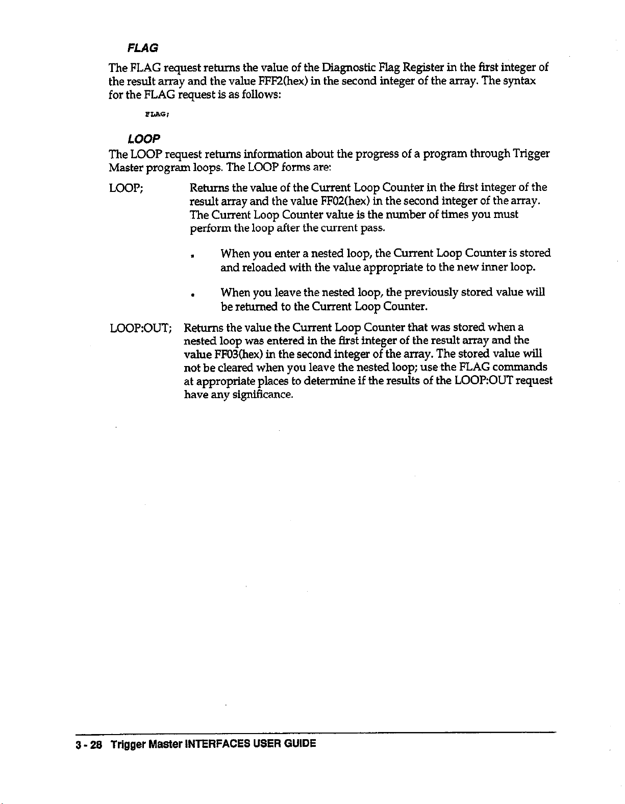
FLAG
The FLAG request returns the value of the Diagnostic Flag Register in the first integer of
the result array and the value FFl?Zfhex) in the second integer of the array. The syntax
for the FLAG request is as follows:
LOOP
The LOOP request returns information about the progress of a program through Trigger
Master program loops. The LOOP forms are:
LOOP;
LOOP:OUT;
Returns the value of the Current Loop Counter in the first integer of the
result array and the value FF02fhex) in the second integer of the array.
The Current Loop Counter value is the number of times you must
perform the loop after the current pass.
When you enter a nested loop, the Current Loop Counter is stored
.
and reloaded with the value appropriate to the new inner loop.
When you leave the nested loop, the previously stored value will
.
be returned to the Current Loop Counter.
Returns the value the Current Loop Counter that was stored when a
nested loop was entered in the fhst integer of the result array and the
value FFO3(hex) in the second integer of the array. The stored value will
not be cleared when you leave the nested loop; use the FLAG commands
at appropriate places to determine if the results of the LOOPOUT request
have any significance.
3 - 26 Trigger Master INTERFACES USER GUIDE
Page 49

STATUS
The STATUS request returns the value of
result array and the value FFFSfhex) in
the Status
the
second integer of the array. The contents of
the Status Register are in the following format:
The bits REG2, REGl, and REGO determine which data register is accessed.
A TRIG DET bit value of 0 indicates you have issued an ARM command and a
value of 1 means the conditions of your ARM command are met. (The TRIG DET
bit is valid only when Trigger Master is not executing a program.) During
program execution, this bit is also set, but the bit is automatically cleared on the
next microsequencer clock cycle (therefore, you may never see this bit set).
During program execution, use the ARM bit of the TRIG request to determine
this same
information.
An INT bit value of 1 indicates the board has generated an interrupt.
An INT-EN bit
value
of 1 indicates Trigger Master is set to generate interrupts.
Register in the first integer of
the
A RUN bit value of 1 indicates a program is executing.
The syntax for the STATUS request is as follows:
USING THE Trigger Master DRIVER
3 - 29
Page 50

TRIG
The TRIG request returns information about various registers. The TRIG forms take
several extensions as follows:
TRIG;
ARM TRIG
0 0
0 1
1 0
1 1
Returns the value of the Trigger Latch Register in the first integer of the result
array and the value FFF4(hex) in the second integer of the array. The format for
the Trigger Latch Register is:
The combined values of the TRIG bit
Definition
Inactive
Armed to Detect Trigger (program execution only)
Outputting Triggers
Semi-Sync Output (program execution only)
When executing a
conditions of your 1
SEMI trigger, the TRIG bit will also be set while awaiting the completion of
the handshake.
The CHG-CHl bit (channels 6-1 values indicate if trigger inputs have
been latched. In immediate mo d e, the channel bits remain set until
issue an ARM. command. When executing a program, the bits are
g tsz next mlcrosequencer clock, therefore you may never detect them
rogram, the ARM bit will be set while waiting for the
RM command to be met. If you had programmed a
and
ARM bit are defined as:
ou
Y
c eared
Returns the number of trigger matches yet to be detected or output (Trigger
Repeat Counter) in the first integer of the result array and the value FFoo(hex) in
the second integer of the snay.
Returns the value of the Delay Counter in the first integer of the result array and
the Trigger InpWPrescaler register value in the second integer of the array. Refer
to the STCSTAT subsection “Making Requests in the Programming Languages”
for details on interpreting the results.
The Delay Counter resets to its initial value after counting down to 0. You can
use a flag after a wait in a program to verify the end of a delay or use the TRIG
request to verify the end of a trigger sequence.
TEI0:Ih-I
Returns the Trigger InputJPrescaler Register in the first element of the result
array and FFFS(hex) in the second element of the array. The format for the first
element is as follows:
3 - 30 Trigger Master INTERFACES USER GUIDE
Page 51

WAIT
The WATT request returns the value of the Delay Counter in the first integer and the
Trigger Input/Prescaler register value in the second integer. Refer to the section “Values
Returned by STCSTAT” for a discussion on interpreting the results.
The Delay Counter resets to its initial value after counting down to 0. You can use a flag
after a watt in a program to verify the end of a delay. The syntax for the WATT request is
as follows:
3.7 SICLOAD
Use STCLOAD to load a binary file into Trigger Master program memory. The binary
file can contain up to 1024 bytes and will normally be generated by STCCOM.EXE (refer
to either Chapter 4 or the following STCDUMP command description). STCLOAD
accepts two arguments: the first argument is the file name to be loaded, and the second
argument is the variable to receive the status returned by the driver at the completion of
the command.
Calling STCLOAD from BASICA
The following program segment illustrates calling STCLOAD from BASICA.
Note:
The actual state of the bigger lines can be determined for diagnostic
purposes, however trigger detection is based on latched transitions.
930 BnaaaMsS 5 “-.aat”
lOB0 ’
Calling STCLOAD from C
The following program segment illustrates calling STCLOAD from the C programming
language.
USING THE Trigger Master DRIVER 3 - 31
Page 52

Calling STCLOAD from QuickBASiC and VisualBASIC
The following program segment illustrates calling STCLOAD from QuickBASIC and
VisualBASIC.
Calling STCLOAD from TurboPascal and TurboPascal for Windows
The following program segment illustrates calling STCLOAD from TurboPascal.
STCTP.LIB is a speclal interface to TurboPascal that accepts a standard TurboPascal
s&g. STCLIB.DLL is a general DLL that expects so-called “C” strings. To send strings to
the DLL in TurboPascal for Windows, create a string with a NULL character on the end
outside the call, and pass the “second element” of the string in the call.
3.8 STCDUMP
Use STCDUMP to store the contents of Trigger Master program memory into a file. You
can then use the STCLOAD command (previously described) to load the program back
into Trigger Master program memory. The STCDIJh4P command accepts two
arguments: the first argument specifies the file name and the second argument is a
variable that receives the status returned by the driver at the completion of the
command. The file will contain 1024 bytes in binary format.
Calling STCDUMP from BASICA
The following program segment illustrates calling STCDUMP from BASICA.
930 BILBWS I “exe.m.dat”
Calling STCDUMP from C
The following program segment illustrates calling STCDUMP from the C programming
language.
3 - 32 Trigger Master INTERFACES USER GUIDE
Page 53
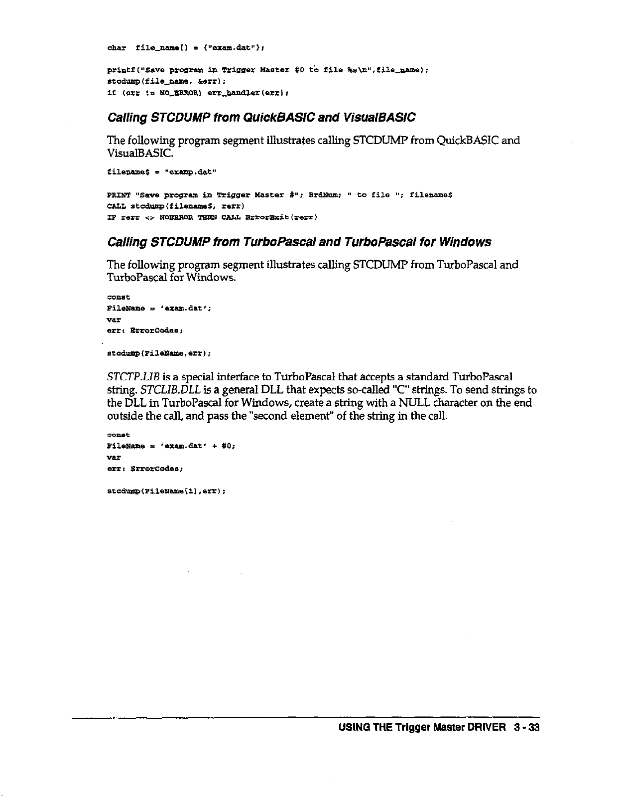
Calling STCDUMP from QuickSASlC and VisualSASlC
The following program segment Illustrates calling STCDLJMP from QuickBASIC and
VisualBASIC.
Calling STCDUMP from TurboPascal and TurboPascal for Windows
The following program segment Illustrates calling STCDUMP from TurboPascal and
TurboPascal for Windows.
STCTP.LIB is a special Interface to TurboPascal that accepts a standard TurboPascal
string. STCLIBDLL is a general DLL that expects so-called ‘T” strings. To send strings to
the DLL in TurboPascal for Windows, create a string with a NULL character on the end
outside the call, and pass the “second element” of the string in the call.
CO-t
PileName = ‘*xam.aat’ + YO;
W
erri BrrOrcoaes;
USING THE Trigger Master DRIVER 3 - 33
Page 54

Page 55

4.1 INTRODUCTION
This chapter presents programmin g examples for each of these languages supported by
Trigger Master: BASICA, C, QuickBasic, and TurboPascal.
Many of the programmin g examples check the status argument after each call; once the
program has been debugged, it may only be necessary to verify that the board is
available (following the STCINIT command). Both the STCCMD and STCSTAT
command set
by the driver. If a nonzero error is returned, check the position variable to see where the
error was encountered.
Most of the examples use a separate STCCMD call that contains a single command.
Using this method allows easier commenting of the code and assists in the debugging
process. You may include a single string with multiple commands in the STCCMD call if
you separate each command with a semicolon.
an
integer to the position of the last character
Chapter 4
PROGRAMMING EXAMPLES
in the string that
was parsed
Notes: The string length limits are 255 characters for BASICA and 256 characters
for TurboPascal.
Trigger Master executes commands as they are parsed. If Trigger Master
encounters an error in a multiple-command string, it executes all valid
commands prior to the command ln error.
In an STCSTAT call, Trigger Master returns after the first semicolon (Trigger Master can
only process one request per request string).
PROGRAMMING EXAMPLES 4 - 1
Page 56

4.2
4 - 2 Trigger Master INTERFACES USER GUIDE
Page 57

PROGRAMMING EXAMPLES 4 - 3
Page 58
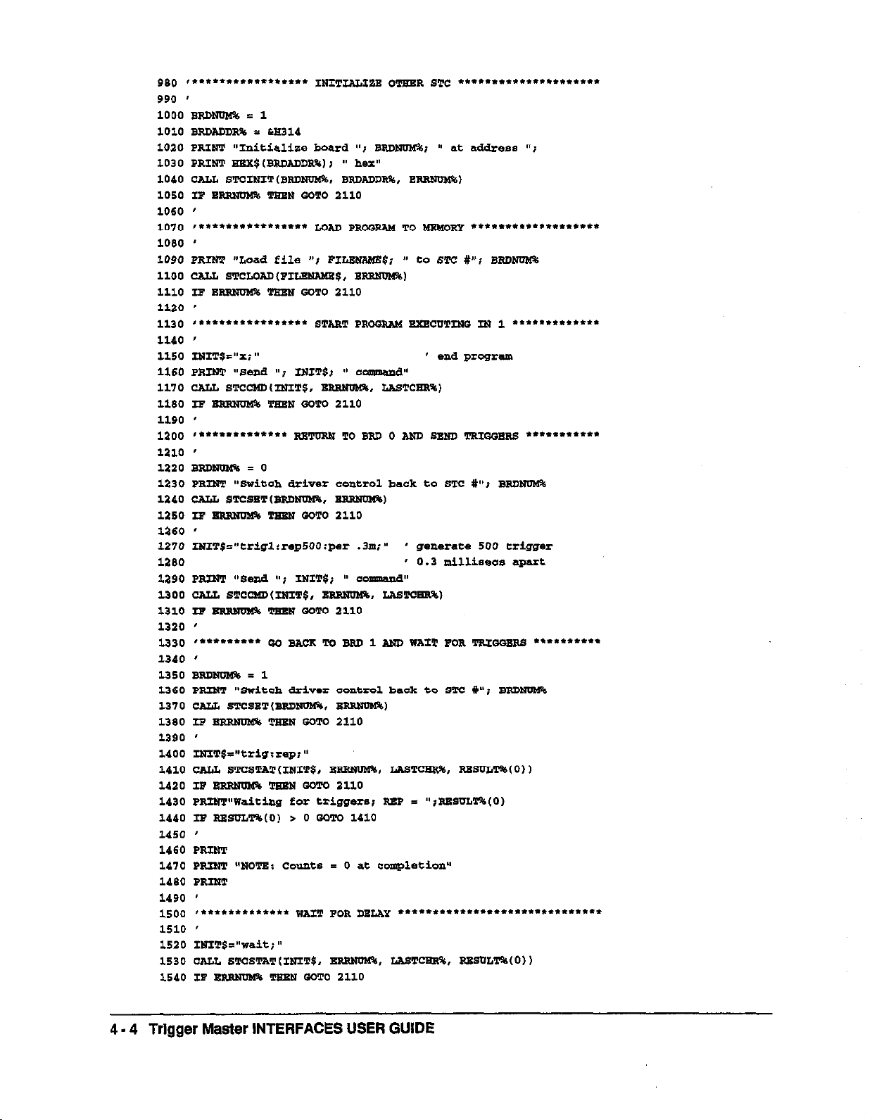
980 t..*.........t.... INIeJm*gB 0-n STC . . . ..**........**....
990 '
1000 wPDNln.f?6 c 1
1090 PRINT “Load eile “i FII.ENANE$; a to 6T-Z U”; END1100 CALL 89!CLcAD(P1Lw~$, BRIINma$)
3.110 IP En mm GCTC
ano
1120 '
1130 ~................ s*meJ pp.- *cmafJ m y, . . . . ...**....
1140 '
1150 INIT$="Xi" ' end prcweam
1160 PRINT "Send "i INIT9J 88 Ccamand"
1170 CALL STcwtINITC, BRRMIM9, LrsTCwN%)
1180 IT - Tam K-m 2110
1190 '
1200 ,............. mT[IRN TO BW 0 - s- mQQg= . . . ...*....
1210 '
I.220 BmNom = 0
1270 ~ITg="er~glrrag500:~~~ .9m;* ' generace 500 trigger
1290
* 0.2 millisecs apart
1290 PRINT "send "1 INITS; " Coxanrmd"
1200 CUL 8Tcw(INIw$, -.
IASTCERW
1310 IF EPnBm!% TEm GCTC 2110
1220 '
4 - 4 Trigger Master INTERFACES USER GUIDE
Page 59
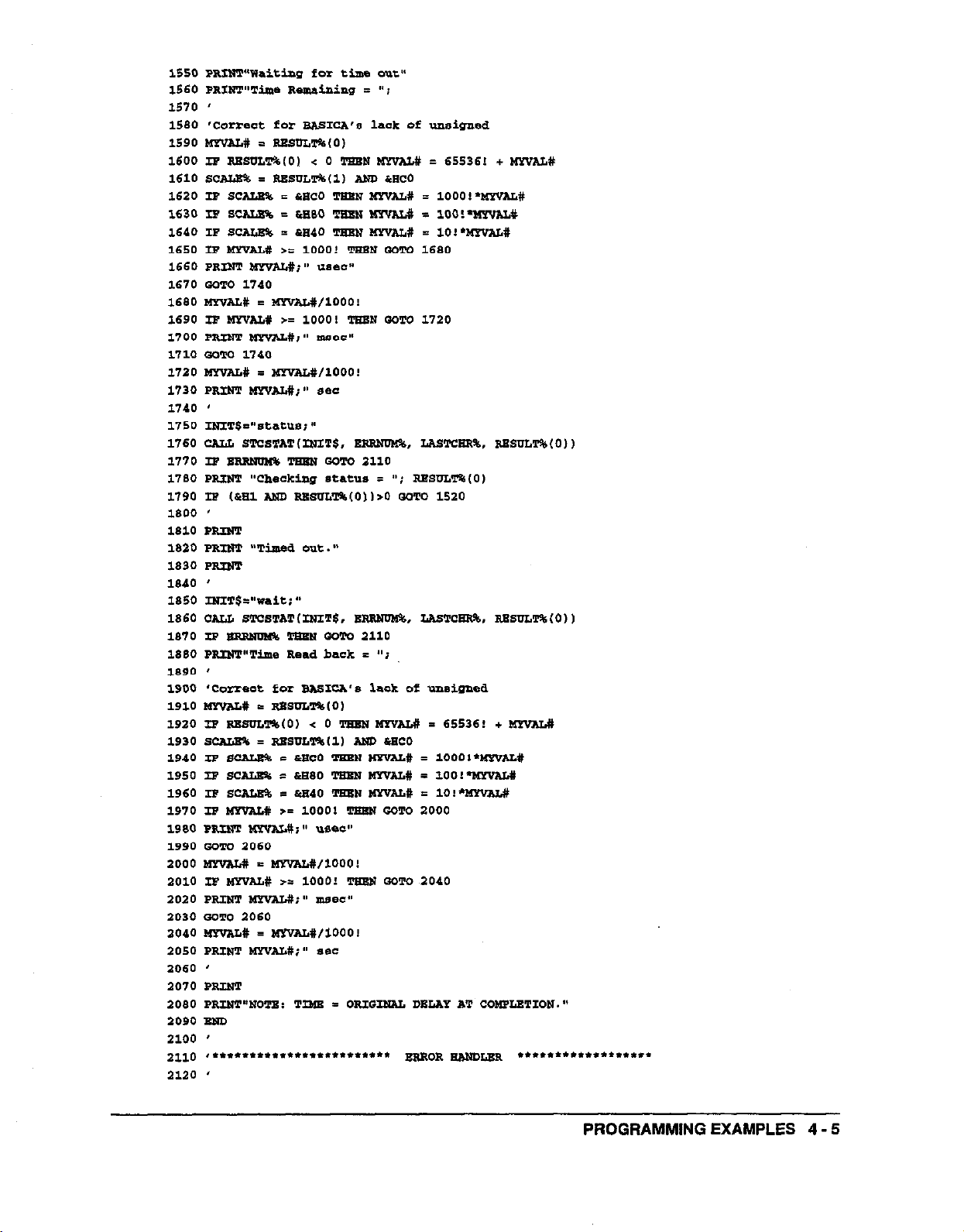
1590 'COII*Et fer BAsIcA' lack Of urdsnnad
1590 tdmmL# s ssscLT%(o)
1600 IX RBSCLT%lO) < 0 TSwN w-%U# = 65536! + mw&f
1610 scAta% = RsSCLTk(1, Am iieco
1620 IF SEALS% E cm20 TEEN WYVALS = 1ooo!*wYvAL#
1630 Ip ScAIm E ha60 TEE" l&Yv?a = loo!*-*
1640 IF s- = rB40 TBBN MYvAL# = lO:*mvAL#
1650 IF mALII >E lOOO! TESN QCTC 1680
1650 PRINT aYvAL#I" -aae)E-
1670 SCTC 1740
1680 MYVALX = MwaL#,1000!
1690 IP MYVALY >= 10001 mm WTC 1720
3.700 PRMT 3lYvALsi" maBC"
1710 scm 1740
1720 tmvz&w I MIvAL#,1000!
1730 PRINT MFf*uti" see
1740 s
ma0 PP.Im "Timed out."
1830 PSIUT
1640 '
1850 mIT$="waie;~
1860 CALL srrslvATtrsnT$, Bn, rAsTCKR%, RwscLT$(O))
1670 IF sBsNma% TmLT mm 2llO
1880 PRIWT"Time Read
1690 '
1900 'Cozzeat for BAsICA's
1910 MYnILs = RsscL*(o,
2920 I9 RBSCLTa(O, < 0 lggpl BB"AL# = 65536! + WWAL,,
1930 s- = RBScLI%(l, MD, &WC0
1940 IF s- 5 kwco THBN wxvN.6 = 10001*IbPVAL#
1950 IF SC- I LBBO Twm w3vaL# =1001-la-wAH
1960 I9 s- E &a40 mt? sIvAL# = lO!-l4wAL#
2970 IB MxvAL# >' 10001 Tswn GCTC 2000
1990 PP.INw ttxvG#;" UBBC"
1990 Gem 2050
2000 MYw&# E -#,looo!
2010 IF MwAL# >= lOOO? TSEU COT0 2040
2020 PRINT l6rvALsi" mdec"
2030 Sam 2060
2040 -I = -#/loo01
2050 PRINT MF,AL#;" SJBE
2050 '
2070 PRINT
2060 PRIm"*cTs: TIME I CRIO~ DBLAY a-i- CCM.FLETICN."
2090 Sam
2100 '
2110 ,...............*......." -cR -m . . . . . . . . . . . . . . . . . .
2120 '
back
I "i
lack
of ur,sigmd
PROGRAMMING EXAMPLES 4 - 5
Page 60

2130 PRINT "Drivtlr returned "I2140 '
2150 '
2160 '
2170 PRINT
2190 PRINT
2190 STOP
2200 '
2210
,.....**............. -I- =mcg -m
2220 '
2230 PRINT "IEEE Error UL Line "i6SI.i "Error Nvmber = "iERR
2240 STOP
. . . . . . . . . . . . . . .
4 - 6 Trigger Master INTERFACES USER GUIDE
Page 61

4.3
C LANGUAGE EXAMPLE
,,...............................................................
I,
,I exampc.c
//
,,..........."..................................,...............
#include <stdio.h>
#include <string.h>
Xincludr, <gragh.h>
#includa <stdlib.h>
#include
/I
"stc.h"
PROGRAMMING EXAMPLES 4 - 7
Page 62

4 - 8 Trigger Master lNTERFACES,USER GUIDE
Page 63

( (
stcstot,"trig:r*p;", Per+, rpos.ret~"al*e~; stcstot,"trig:r*p;", Per+, rpos.ret~"al*e~;
printf("waiting for
printf("waiting for
triggers; RBP = Od\n~~,ret~value[ol);
triggers; RBP = Od\n~~,ret~value[ol);
if (err != N0g9Juw.1 *rr2mnd1*r,*rr,: if (err != N0g9Juw.1 *rr2mnd1*r,*rr,:
, ,
while (r*t~valu*~Ol~O); II wait for trigger inputs
do
(
etcstat , w*it; 08, &err, LpO.s,r*t~"a1u*) ;
prilltf("Tbn* rem.¶kri*g = "1;
if (err !E N0~.6RRoR, *n~hamdler(en);
time_semai!li.ng 3 r*kmt, r*t~valu*101;
witch (ret-value111 h OrcO) C
EDIIB oxco:~
t.h-madning l = 1000;
break;
I
case 0x90: (
time~remaining l = 100;
breal:
1
cas* or401c
tim*Jema-g *= 10;
break;
I
I
if (times-smainimg < 10001 C
printf("%.Of us*c*\n".tim~r~ining);
I
*lNZ(:
time-remaining 5 th~rema~/looo.o;
if ,timeJrmlinino < 10001~
printf (%.4.f msecs\n".tkae~emainingl;
1
PROGRAMMING EXAMPLES 4 - 9
Page 64

stcst*trI'v*iti'I, PQrr, &pcl*,r*t~"*l"e~;
printf("\nTimd out.
Wait
returns "I;
if ren I= N0J9xoR1 *rr-handl*rlerrli
time-Jxrm*ping
sw*tCh rret~"*lue (1,
I (float) ret~"*lue~0li
& orco, I
case oxco:t
time_remsiniag
break;
I
ealie 0260: f
CimeJerdning
breaki
1
a*s* 0x40:<
tb.QrruMining ‘SlO,
break;
I
I
it
,time_rainins
print*
I
(%.Of u~*~~\n",time_remainingl;
else1
timeJmmaini.ng = tim*~remaining/looo. oi
if ,the-mmdning -c 10001c
~rlntt("%Af lnsecsb", time~remuiniagl i
I
else<
time~remainkg
pri.atf~"%.Of **os\n~',tim*_re.maining);
I
I
*. 1000)
l = 100;
<
10001~
q
timeJ~ining/1000.0;
4.10 Trigger Master INTERFACES USER GUIDE
Page 65

4.4 QuickBASIC EXAMPLE
r~.“***ft.*f*.~.tt*.~*.**.~*..~**.~~.~***...*.*..~“**~**...*~.~..
PROGRAMMING EXAMPLES 4 - 11
Page 66

4 - 12 Trigger Master INTERFACES USER GUIDE
Page 67

PROGRAMMING EXAMPLES 4 - 13
Page 68

4 - 14 Trigger Master INTERFACES USER GUIDE
Page 69

PROGRAMMING EXAMPLES 4 - 15
Page 70

Page 71
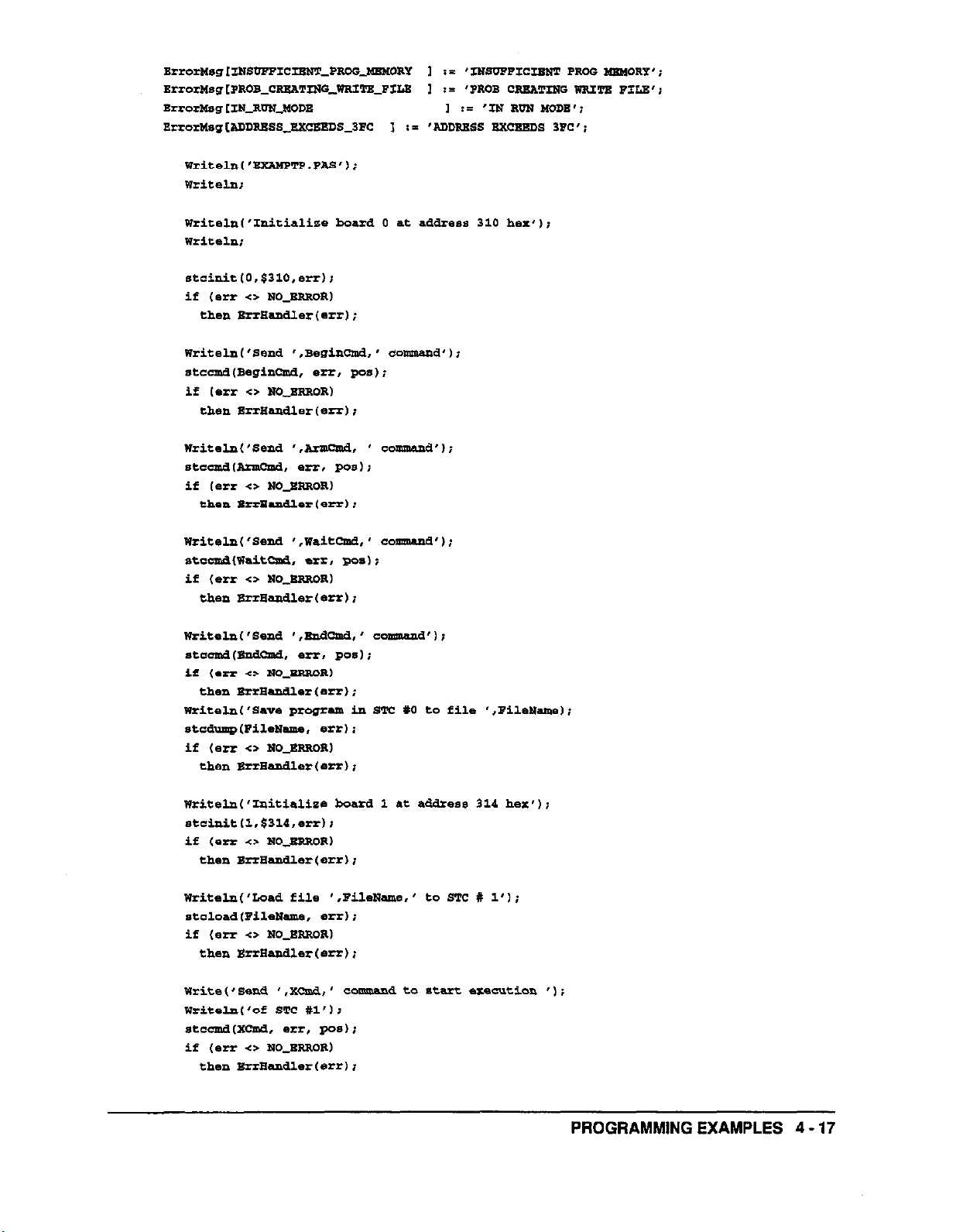
stcinit~0,$310,.rr~~
if (err <> NOJZRRORI
then BrrBandl.r(.rr,;
writ.lrL~'s.na ',s.gincma,' clomm.lad'l;
stcand(B.gincmd, .rt, ~0s);
If (err c> NOJRROR)
then SrrHe.rdler~.rr~;
writ.ln~‘s.nd ‘,Anncua, ’ commana’l;
StCcmdPZZllCM, err. Pas);
if ,.rr c> NO_BRROR)
then Brrean6l.r t err1 i
writ.ln('S.nd ',waitcrsd,' commend');
s+cdWPaitcPd. .m, Bo.1;
if (err <s N0_BRRoR1
then BnBandl.r(.er);
PROGRAMMING EXAMPLES 4 - 17
Page 72

WritelnL'Switch driver coatxol back to ST-2 #O'lt
stcs.t(O'..rrl I
if
1e.r c> No~sRRoRl
then ErrE.rdler(.rr),
Writ.~'s.nd '.ml*Qnd,
writ.ln~'from STC PO to STE Xl',>
stccma(wrig-, erx, pQs,i
if Ierr <> NOJPAORI
then Eermxk3l.r(.rrli
Writaln('Switch driver co=trd to STC Itl'l;
*ta*.t,1,.*,;
if (err <> NO_ERIIORl
th.n ErrE.nU.r(.rr);
' c-a to send
triggers
',I
4 - 18
Trigger Master INTERFACES USER GUIDE
Page 73

mp.?&.t
stcsrae('wait;'.
set, pos.R.tv.lu.1o1);
writ., ‘Tim. remaining = ’ I;
if (err <> NOJRRORI
then BrrE,.m3l.r(errl;
TaeR.maininrr := R.t"alu.IO,;
aas. ,n.t"alue~l, and SCO) Of
5co: Tim.R.mainina := 1000*Th.Rsn?‘ining;
$80: Tim.Ramaining := loo*T~R.~ining;
$60: ThR.asaj.ning := lo*ThsRemoi-;
end;
if ITbaRtunaining < 1000~
then WritelnlTimeRemaini, ' usecs')
else
kJ.pfn
l%m..Rsmaining II TimsRemainiilg11000.0;
if Il5meRemaining e 10001
thsn WritelntTimeRemaininrr.' msecs~~
else
begin
TimeRsmainine 1= T~R.maining11000.0;
writ.lrkm%ln.R.mai, ' s.os'l;
end;
end;
stastat , '*tatus; ',
Writ.ln('Ch.cking st.tus = ',n.tR.g[O,,' ha',;
*Ill, **.R*rR*gI0,~;
if (err <P No-ERROR)
then BrrBandl.s(.rrIi
until (($01 and R.tR.47~01)=0,1 (*wait while prcgmm is elecutiag 0)
stcstat('wait; ', err, pos,R*tValu*~Ol~ I
writeln,
writ.1n~'Fim.a out. wait ret- '1;
if (err <> aro_ERnOR)
then srr-er~err, ;
PROGRAMMING EXAMPLES 4 - 19
Page 74

TimeRemaining il R.t"Val". (0, i
aas. m.tV*lu.~lI and sao, of
$00: Ti.m.R.mainin# := 1000*TimeR~iBiag;
$80: TimeRemaining i= loo*Tim.Rsmaminp,
$40: TimeRemaining := lo'Tim.R~ining;
end,
if (TheRemaining < 10001
theI2 wrie.ln~Tim.R~ini, ' usems'~
else
k?.giTl
Tim.R.lMining I= ria.R.mamingllooo.o;
if vAQ&mm.ining -G 10001
then
WritelnPJimeRemaining,
m..~.',
else
begin
TimeR-inir,g := ThrL.R.ulaining/looo.o;
w.rit.lncThsR.main,' **c*0>
.pd;
end;
writ.ln~'NOTx: A= oompletion WAITI returns the original delay.'11
.d.
4 - 20 Trigger Master INTERFACES USER GUIDE
Page 75

5.1 INTRODUCTION
One Trigger Master feature is its ability to run programs from its own memory. If your
word processor can create an ASCII/DOS output, you can create programs and then
“compile” them using the STCCOM.EXE program. The section “The Command Set” in
Chapter 3 describes the available commands. All commands, except BEGIN, CONT, and
X, are supported in programs for Trigger Master memory (the END command is
optional). You may use tabs, spaces, and returns to make your file more readable and
enter comments with beginning and ending asterisks.
Note: You can also develop programs from PLAYWIN.EXE and PLAYDOSEXE.
To use STCCOM enter the following comman d line at the DOS prompt.
Chapter 5
CREATING PROGRAMS FOR
Trigger Master MEMORY
*teEan xourSOurcaFil.
STCCOM generates a list file with the suffix UT; this file lists each command on a
separate line.
. If there is no error in the co mmand, the first column of the listing shows the location
in memory
where the command starts and the command.
. If there is an error, the command is listed followed by the error message.
If your file contains no errors, STCCOM generates a load file with the suffix .LOD; this
file can be loaded into Trigger Master using STCLOAD.
Thii sample source file produces the listing which follows:
Source File
l
This is s file for us.
so 33;
Armrep40;
wait 2oou;
trig2 ;
lOOPi
* perfoIls loop 33 times -
l arm to detect 40 triggers on line 1 l
l wait 300 micro **cords l
* gs~exat. trigger on line 2
with SPXOM ’
CREATING PROGRAMS FOR Trigger Master MEMORY
5 - 1
Page 76

5 - 2 Trigger Master INTERFACES USER GUIDE
do 23;
Aml:rep40;
wait aooui
trig2;
loopr
Page 77

6.1 INTRODUCTION
Trigger Master is capable of performing the control functions required by a small data
acquisition system. While
generate trigger outputs, wait for trigger inputs, and generate delays. By occasionally
calling on the PC to move data, make decisions, or bring other resources to bear, Trigger
Master can implement a data acquisition system that shares the PC with another DOS
function.
‘Thii chapter describes creating a Terminate-and-Stay-Resident (TSR) program for
Trigger Master. The TSR program operates in the background while you execute another
DOS program. You create the TSR by linking STRCRUNC.OBJ to the program module
that you have written and compiled in C. Execute the resulting .EXE file by typing the
file name. For example, to execute the sample program TSRC, type the following at the
DOS prompt:
Chapter 6
CREATING A BACKGROUND DATA
ACQUISITION SYSTEM FOR DOS
running a program from its own memory, Trigger Master can
You can only instaIl a Trigger Master TSR once. If you attempt to install a second TSR
while one Trigger Master TSR is currently installed, the system will return an error
message. You must dAnstaB one TSR before installing another Trigger Master TSR or
running a TSR again. De-install a TSR by using the /d option in the command line, as
shown in the following example:
When you deinstall a TSR, you receive a message that the TSR is de-installed.
If you successfulIy de-install the TSR, you can then run your program again. TSRs
control certain computer interrupts; when you attempt to deinstall the TSR, the TSR
tries to return interrupts to the state prior to the installation of
is successful, the TSR is de-installed.
Note:
The TSR program executes as any other program. When the TSR terminates, it returns
the DOS prompt allowing you to run another program. Unlike other programs,
however, a portion of the TSR code remains resident in memory
terminates.
Occasionally, another program that controls interrupts will execute after
the TSR is lnstalled. If this occurs, you may have to reboot the computer
in order to run the TSR again.
the
TSR. If this procedure
when the
TSR
CREATING A BACKGROUND DATA ACQUISITION SYSTEM FOR DOS
6 - 1
Page 78

While your computer is executing your current application, such as a word processor or
spread sheet application, the TSR code remains dormant. When certain events occur,
such as an interrupt from Trigger Master, the computer switches to the TSR resident
code. The TSR performs whatever task Trigger Master requires and then returns to the
previously executing application. Other events that can switch control to the TSR are
interrupts from a GPIB controller or another board in your computer. Generally, you
will be unaware that you are sharing the computer; you may notice an interruption if
the computer must
move
a lot of data between instruments or disks.
This chapter discusses the general
available to log data and watt on interrupts. The chapter also presents an example of a
TSR, a portion of the log flle generated by the example TSR, and the details involved in
constructing a TSR in the C programming language.
6.2 THE TSR STRUCTURE
Create your TSR by liing your C program to the object file STCRUNC.OBJ. If you are
using a GPIB controller, you must include the appropriate IEEE library in your link
statement.
You must name the main module of your program STCTEST. The STCTEST module will
call procedures from STCRUNCOBJ, IEEE.LIB, or custom functions and procedures.
Although, all your test programs must contain STCTEST, your source and .EXE files can
be given any
chapter.
The intent of
then log data to a disk. Therefore, this TSR makes use of specialized and restricted calls.
These calls, which are discussed in detail later in this section, are as follows:
name.
the
The details of constructing the TSR are discussed later in this
sample TSR ia to use one Trigger Master to control a measurement and
NOKPC488 Produces an error exit if a KPC4882TM controller is not
shucture
found.
of the TSR and the functions that are
MISSINGGPIBDEV Produces an error exit if a GPIB device is not found.
STCRUN Initializes Trigger Master and GPIB (if used), starts Trigger
Master program execution, and converts your program
into a dormant TSR that waits for a Trigger Master
interrupt.
Note: The STCRUN call must appear in your program following the
NOKPC488 and MISSINGGPIBDEV calls, but before any other calls.
WAITONSTC Restarts Trigger Master and waits for Trigger Master
interrupts.
JMPWAITSTC
Starts Trigger Master at a new program location and waits
for Trigger Master interrupts.
WAITONGPIB
Waits for an interrupt generated by a KPC4882TM
controller.
WAITONAUX Waits for an arbitrary interrupt.
6 - 2 Trigger Master INTERFACES USER GUIDE
Page 79

STCFLAG
Returns the value of the Trigger Master flag register to a
TSR.
STCLOGBIN
STCLOGDATE
STCLOGFLAG
Logs binary data to disk
Logs the date to disk.
Logs the Trigger Master flag register value to disk
STCLOGPROGCNT Logs the Trigger Master program location to disk
STCLOGSTR Logs a string to disk
STCLOGTIME
Logs the time to disk.
STCEXIT Terminates the TSR.
Normally, your STCTEST program will perform certain initialization functions. If you
are Using a KPC488xxx GPIB controller, you will generally initialize the controller and
certain other devices. If the controller or devices are not present, you should exit the
program using the NOKPC488 or MISSINGGPIBDEV calls; thii procedure displays an
error message.
At some point you will call STCRUN to start executing the Trigger Master onboard
program, convert the program into a TSR (with a return to DOS), and cause the TSR to
wait for an interrupt from Trigger Master. When Trigger Master generates an interrupt,
control is returned to the TSR. At that point, you can take one of the following actions:
. Log data to the disk using one of the STCLOGxxx functions.
.
Read the Trigger Master flag register using STCFLAG.
. Put the TSR back to sleep by resuming operation of Trigger Master and then
generate another interrupt using WAITONSTC or JMPWAITSTC.
. Put the TSR back to sleep to wait for another interrupt using WAITONGPIB or
WATTONAUX.
.
Terminate the TSR using STCEXIT.
NOKPC488 and MISSINGGPIBDEV
You can use one KPC488xxx GPIB controller at the standard address in your TSR. At the
beginning of your program, you can use the IEEE library call gpib-board-present to
determine if a GPIB controller is present. If a controller is not present, you should call
NOKPC488 to exit your program. Since the TSR can only support a single GPIB
controller, the NOKPC488 call does not require an argument.
If you are using GPIB devices, you may find that a GPlB device tunes out. If this
happens, you should exit your program by calling MISSINGGPIBDEV with the GPIB
device address as the argument.
If you have not yet called STCRLJN, the calls NOKPC488 or MISSINGGPIBDEV will
display an error message on your monitor. Otherwise, a tone is generated, an error
message is placed in your log file, and program execution stops.
CREATING A BACKGROUND DATA ACQUISITION SYSTEM FOR DOS
6 - 3
Page 80

STCRUN
STCRUN must be the first Trigger Master call (following the calls NOKPC488 and
MISSINGGPIBDEV) in your program. STCRUN initializes Trigger Master and software,
causes Trigger Master to start executing its program, and starts your program operating
as a dormant TSR waiting to be awakened by an interrupt from Trigger Master.
STCRUN accepts seven arguments and incorporates the functions of the STCINF and
STCLOAD calls. The~flrst argument is your Trigger Master board address and the
second argument is the name of the file to be loaded into Trigger Master program
memory. The third argument is the name of the disk file to which the TSR is to log data.
The fourth argument is the interrupt level specified for Trigger Master (the purpose of
this TSR is that it will remain dormant until awakened by an interrupt from Trigger
Master). STCRUN checks for a valid XT or AT level, but has no way of knowing if you
are using an AT board.
Every call which waits for an interrupt accepts a “ticks” argument. This argument allows
you to specify
the
length of time the TSR should wait for an interrupt to occur before
logging off with an error message.
. A “ticks” value of 0 disables time checking; the TSR will never log off, but will wait
forever for an interrupt.
. Nonzero “ticks” values specify the number of computer clock interrupts the TSR
should wait before logging off; the computer generates a clock interrupt about 18.2
times per second or about 1 clock interrupt every 55 msec. You should always
specify a
minimum of 2 ticks since you may set your ticks just before a clock
interrupt.
STCRUN accepts two final arguments that are interrupt levels generated by either your
KPC488xxx GPIB controller or an auxiliary board. Choosing level 0 for these interrupts
disables the interrupts. If you choose a level for the GPIB controller, the KPC488xxx will
be initialized to generate an interrupt on the receipt of an SRQ (GPIB Service Request).
You must perform a serial poll of the GPIB device to clear the SRQ.
Setting up a nonzero auxiliary interrupt sets up an interrupt handler for the interrupt; it
is your responsibility to program the card to generate the desired interrupt and, if
necessary, to clear the board’s interrupt.
STCRUN checks for valid interrupt levels and verifies that different levels are used by
the
different functions, however STCRUN does not know if you are duplicating a level
that is used by another board ln your computer.
Note:
If you use an AT level, ensure your board supports the AT levels. You
board jumpers must reflect the levels specified in STCRUN.
If STCRUN encounters a problem, such as a opening a flle or a duplicate interrupt level,
it displays an error on the monitor and terminates program execution. If STCRUN does
not encounter any problems, it opens a log file, your program becomes a TSR, and the
computer displays a line indicating the TSR is installed. You are then returned to the
DOS prompt.
6 - 4 Trigger Master INTERFACES USER GUIDE
Page 81

The opened log file contains a standard header similar to the following:
The first three lines contain the program name and date and time of creation. The fourth
line indicates the number of memory paragraphs (in hexadecimal notation) your TSR
occupies. To convert the memory paragraphs to bytes, add a 0 to the end of the number
and convert to decimal. In the example, the TSRCEXE program uses about 21 Kbytes
(51OOfhexD. The program contains the GPIB library.
WAITONSTC and JMPWAITSTC
Calling WAITONSTC or JMPWAITSTC executes Trigger Master again and puts the TSR
back to sleep (to wait for another Trigger Master interrupt). These calls contain the tick
parameter, described for STCRLJN to avoid a hang condition if no interrupt is generated.
Without the tick parameter, the WAITONSTC command is basically a CONTzINT
command that causes the Trigger Master program to start executing at the next step.
The JMPWAITSTC command accepts a second parameter which tells the program
where to start execution and to perform an X nn:INT command. This process allows you
to have multiple programs resident in Trigger Master program memory, jumping to
different code based on previous results or repeating a program any number of times. If
you create your Trigger Master program as an ASCII file and compile it using STCCOM,
you can determine your jump addresses from the list generated by STCCOM.
WAITONGPIB and WAITONAUX
Calling WAlTONGPIB or WAITONAUX puts the TSR back to sleep to wait for an
interrupt from a KPC488xxx controller or other card. Both calls contain a tick parameter
(refer to the STCRUN description for further information).
STCFLAG
The STCFLAG call returns the value of the STCFLAG register, enabling a program to
make decisions based on the progression through the Trigger Master program.
CREATING A BACKGROUND DATA ACQUISITION SYSTEM FOR DOS 6 - 5
Page 82
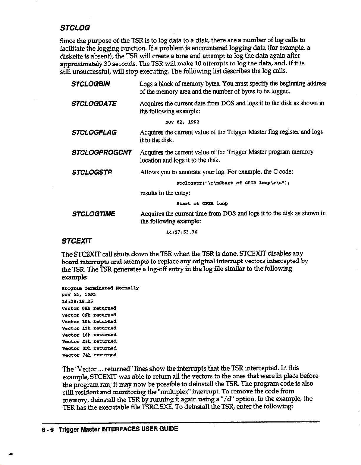
STCLOG
Since the purpose of the TSR is to log data to a disk, there are a number of log calls to
facilitate the logging
function.
If a problem is encountered logging data (for example, a
diskette is absent), the TSR will create a tone and attempt to log the data again after
approximately 30 seconds. The TSR will make 10 attempts to log the data, and, lf it is
still unsuccessful, will stop executing. The following list describes the log calls.
STCLOGBIN Logs a block of memory bytes. You must specify the beginning address
of the memory area and the number of bytes to be logged.
STCLOGDATE Acquires the current date from DOS, and logs it to the disk as shown in
the following example:
NO” 02, 1992
STCLOGFLAG
Acquires the current
value
of the Trigger Master flag register and logs
it to the disk.
STCLOGPROGCNT Acquires the current value of the Trigger Master program memory
location and logs it to the disk.
STCLOGSTR
Allows you to annotate your log. For example, the C code:
sfclog*tr~“\r\nstart Of SPIB lwP\r\n”) I
results in the entry:
smrt Of GPIB 1-P
STCLOGTME Acquires the current time from DOS and logs it to the disk as shown in
the following example:
u:a7r52.7s
STCEXIT
The STCEXIT call shuts down the TSR when the TSR is done. STCEXIT disables any
board interrupts and attempts to replace any original interrupt vectors intercepted by
the TSR. The TSR generates a log-off entry in the log file similar to the following
example:
Program Te-ted Nomally
mv 03, 1992
14,28,18.25
"eater O9h returned
"edmr P9h re4xrned
vector 10h rete-d
"e&or l3h zetumed
"eater 15h returned
"actor 29h
"e.,bx ODh r.turPed
"e~ltoe 74h ~‘~tu,swd
reeurned
The “Vector . . . returned” lines show the interrupts that the TSR intercepted. In this
example, STCEXIT was able to return all the vectors to the ones that were in place before
the program ran; it may now be possible to delnstall the TSR. The program code is also
stiIl resident and monitoring the “multiplex” interrupt. To remove the code from
memory, de&tall the TSR by mnning it again using a “/d” option. In the example, the
TSR has the executable tile TSRC.EXE. To deinstall the TSR, enter the following:
6.6 Trlgger
Master
INTERFACES USER GUIDE
Page 83

The monitor displays a message indicating the success or failure of deinstalling the TSR.
If the log indicates that one or more of the vectors could not be returned, do not deinstall
the TSR.
6.3 AT% LOG
The following example illustrates a portion of the log generated by the program in the
section that follows. Data that has been deleted from the example is indicated using an
ellipsis (...).
CREATING A BACKGROUND DATA ACQUISITION SYSTEM FOR DOS 6 - 7
Page 84

6.4 A TSR EXAMPLE
The following C program can run as a TSR.
*****lr******-+***~****-*~*~**~****~***~**~*~**~****~*
//
// TSRC.C ls C source code for a program which illustrates the
use of stcrunc.obj and ieeec.hb 6 create a TSR program
to run an Trigger Master.
This example uses a PCIP-AWFG as a source and a Keithley
196 as a measuring and data storage device. Alternatively, a
DAS-50 could be used to collect data.
The AWFG is loaded with a seq ence of values which it will
step through as it receives exte al triggers from
Trigger Master.
After some initialization the 196 wlE be triggered to
measure the output
196’s internal memory. Next Trigger Master will trigger the
AWFG causing the AWFG to step to its next output value. The
Trigger Master will generate a delay to allow the AWFG output to
stabilize (as well as any device or circuitry between the AWFG and
the meter).
The meter will be commanded to make the next measurement
and the process will repeat the required number of times.
Finally the stored values will be retrieved and stored to
disk.
rx
from
the AWFG and store the value in the
//
To illustrate the features of the trigger link the test
will be repeated twice: first using the GPIB to control the
196 measurement, and then using the tagger link
The first thne through, GPIB GETS (group execute triggers)
will be used to i&late the reading and the 196 will
respond with an SRQ (service request). Durlng the second
run, Trigger Master will trigger the 196 External Trigger input and
monitor the 196 Voltmeter Complete output.
*uI+I*~Mw********I*~~*~~~~~~~*~*~**~~**~~*
::
#include “stcrunh’
#include “ieee-ch”
#define K196 12
#define DATAJIS 100
// function prototypes from stcrunc.obj.
// function prototypes from ieee-clib.
// GPIB address of KeithIey 196.
/ / Number of points to acquire - must
// agree wlth Trigger Master program.
#define DATA-LEN 23
/ / Length of data string returned by
// Trigger Master.
6 - 6 Trigger Master INTERFACES USER GUIDE
Page 85

void far Pascal stctest0
I
mt BrdType; / / variable for gpib driver board - 0
// if no board present.
int status;
//statusreturnedbygpibcalls-Oif
// timeout.
int 1; // number of bytes transferred by GPIB.
int poll;
int index;
// result of a serial poll.
/ / index for repeats.
static char r[DATAJTS*DATA-LEN];
// array for date returned by K196.
BrdType = gpib-board-presentf);
/ / check for presence of KPC488.
if (BrdType == 0) NoKPC4880;
initialize (21,O);
/ / make KPC488 a controller
/ / at address 21.
, , +IF+*,W+S+,~S+NIIC+Z+SS+W+Z+ NO-,-E ~(~E+W+Z+G+S+UF+~+;~~(G++~+~,Z+Z,~~~
// Comment out the following line if you are using the
// KPC488.2 controller. The KPC488.2 does not support
// listener-present.
iff!listener_present(K196)) MissingGpibDev(K196); / / check for K196
// Set up to measure using GPIB control
stcrun(0x310,
“tsr.lod”,
“tsr.log”,
5,
22,
12
0);
// allow 19 ticks(l+ set) for Trigger Master to return
// use interrupt level 12 on GPIB
// don’t use AUX interrupt
// Load Trigger Master at address 310 hex
// with program TSR.LOD,
/ / log data to TSRLOG,
// use interrupt level 5 for Trigger Master,
spoll~K196,&poll,&tatus~; // clear srq
send fK196,“FOROT3QOIOM8YOK3X”,&status);
/ / device command to set 196 to:
// dc volts, autorange, 1 measurement on
// GET, store each acquisition in 196
/ / memory. store continuously,
// generate SRQ when reading is done,
// terminate strings with <cRscLF>
/ / and do not send EOI.
poll = 0;
while (poll&16 != 16) spollfK196,&poll,&status~;
/ / wait for ready
stclogshf%\nStart of GPIB loop\r\n”);
stclogtime0; // log the time at the start of the loop
stclogstrC\r\n”);
// place carriage return and line feed in log
CREATING A BACKGROUND DATA ACQUISITION SYSTEM FOR DOS
6 - 9
Page 86
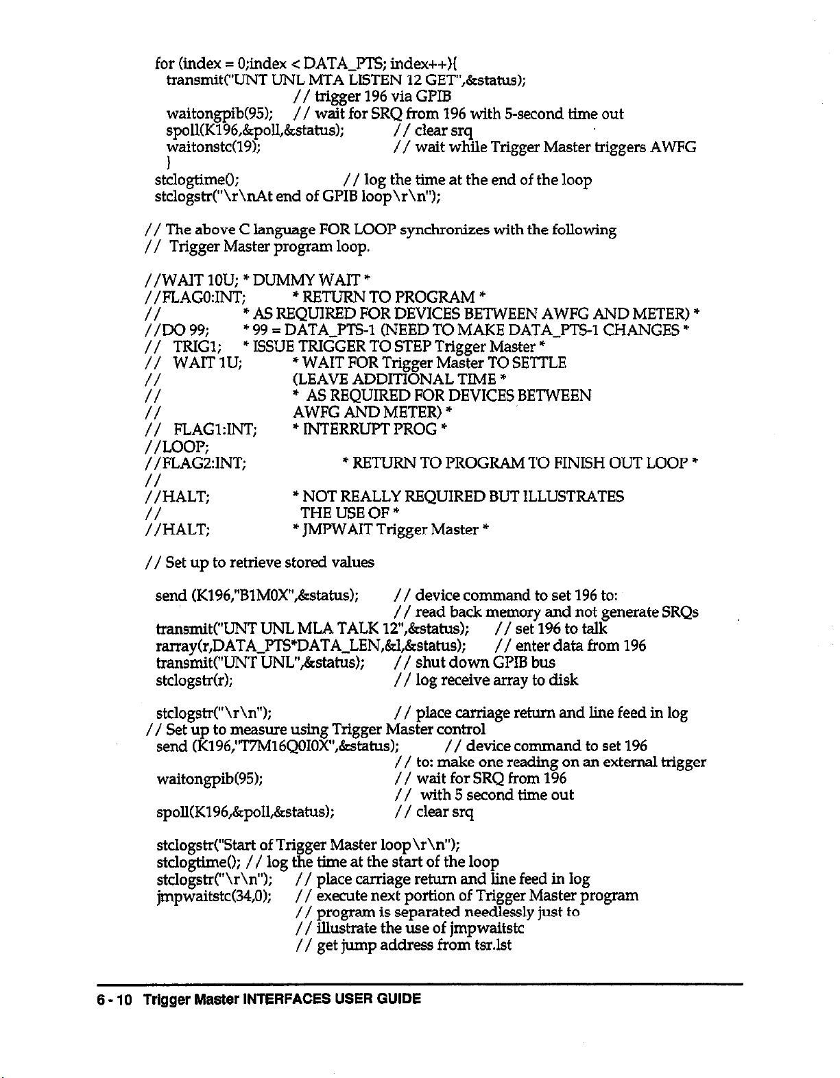
for (index = 0;index c DATA-MS; index++){
transmitf”UNT UNL MTA LISTEN 12 GET”,&status);
// trigger 196 via GPIB
waitongpib(95);
// wait for SRQ$og%qwIth 5-second time out
spoll(K196,&poII,&status);
waitonstc(l9);
// kait while Trigger Master triggers AWFG
1
stclogtime0;
// log the time at the end of the loop
stclogstrf”\r\nAt end of GPIB loop\r\n”);
// The above C language FOR LOOP synchronizes with the foEowing
// Trigger Master program loop.
//WAIT 1OU: * DUMMY WAIT *
//FLAGo:IN;T;
* RETURN TO PROGRAM *
* AS REQUIRED FOR DEVICES BETWEEN AWFG AND METER) *
::Do 99.
// TRIGl;
// WAITlU;
* 99 = DATA-PTS-1 (NEED TO MAKE DATA-MS-1 CHANGES =
* ISSUE TRIGGER TO STEP Trigger Master *
* WAIT FOR Trigger Master TO SETTLE
(LEAVE ADDITIONAL TIME *
::
* AS REQUIRED FOR DEVICES BETWEEN
AWFG AND METER) +
:: FLAGl:INT;
* INTERRUPT PROG *
//LOOP;
//FLAGZINT;
* RETURN TO PROGRAM TO FINISH OUT LOOP *
:LT;
* NOT REALLY REQUIRED BUT ILLUSTRATES
THE USE OF *
::HALT;
* JMPWAIT Trigger Master *
// Set up to retrieve stored values
send (K196,“BlMOX”,&status~;
/ / device command to set 196 to:
/ / read back memory and not generate SRQs
tra.nsmit(“UNT UNL MLA TALK lT,&status);
rarray(r,DATA~PTS”DATA~LEN,&l,&statusJ;
transmitC’uNT uNL”,&statlls);
// shut down GPIB bus
// set 196 to taIk
// enter data from 196
stclogstrfr); // log receive array to disk
stcIogstrf%\n”); / / place carriage return and line feed in log
// Set up to measure using Trigger Master control
send (K196,“T7M16QOIOX”,&status);
// device command to set 196
// to: make one reading on an external trigger
waitongpib(95); // wait for SRQ from 196
// with 5 second time out
spoE(K196,&poII,&status~; / / clear srq
stclogstrf”Start of Trigger Master loop\r\n”);
stcIogtime0; // log the time at the start of the loop
stcIogst$\r\n”);
jmpwaitstcC34,O);
// place carriage return and Iine feed in log
// execute next portion of Trigger Master program
// program is separated needlessly just to
// illustrate the use of jmpwaitstc
// get jump address from tsr.Ist
6 - 10 Trigger Master INTERFACES USER GUIDE
Page 87

// * THIS PORTION OF PROGRAM PERFORMS Trigger Master
;; CONTROLLED ACQUISITION *
//FLAG3;
//Do 100:
1; TRIGl;
* 100 = DATA PTS +
* ISSUE TRIGGER TO STEP Trigger Master *
* WAIT FOR Trigger Master TO SETTLE
:: WAITIU;
//
*AS REQUIRED FOR DEVICES BETWEEN AWFG AND METER) *
(LEAVE ADDITIONAL TIME *
* ISSUE TRIGGER ~0 196 EXTERNAL TRIGGER INPUT *
:: EK2
// ’
*WAIT FOR RESPONSE FROM 196 VOLTMETER
COMPLETE OUTPUT *
/ /LOOP;
//FLAG&INT; * INTERRUPT PROG *
stcIogtime(~; // log the thne at the end of the loop
stcIogstrC’\r\nAt end of Trigger Master loop\r\n”);
// Set up to retrieve stored values
send (K196,“BlMOX”,&status); / / device command to set 196 to:
// read back memory and not generate SRQs
transmitC’UNT UNL MLA TALK 12”,&status);
//set196totaIk
rarray~r,DATAJTS*DATA_LEN,&l,&status); / / enter data from 196
transmIt(“UNT UNL”,&status);
stdogstrfr);
stclogstr(“\r\n”);
stcexit0;
// shut down GPIB bus
/ / log receive array to disk
/ / place carriage return and line feed in log
// measurement done, shut down TSR
I
65 CREATING A TSR FOR C
The intent of this TSR is to service Trigger Master and log data in the background.
Therefore, your program should not perform I/O other than the special log functions
provided. Your program should not use any of the standard C Include files; use
STCRUN Instead of having a function caIIed main your program. You can caII other
functions or procedures from STCTEST.
You should compile your program without stack checking and the normal C libraries.
For Microsoft C, compile your program with the following command line:
Cl /As ,Zl /OS ,c y0urpTmg.c
Then, Iink the result to stcrunc.obj and the IEEE library (if required) as follows:
li* atcw.obj
yollrpmg.obj,yourprog.exe,,iee~488
CREATING A BACKGROUND DATA ACQUISITION SYSTEM FOR DOS
6 - 11
Page 88

Page 89

Appendix A
Trigger Master ERROR MESSAGES
This appendix contains an alphabetical list of Trigger Master error messages and their
definitions.
Error Mesacie
ADD OVER RNG
ADDRESS EXCEEDS 3FC
ARM NEEDS LINE
DO NEEDS VALUE
DO OVER RANGE
DRIVE NOT READY
DUPLICATE STC ADDR
EXCEEDS DO LEVEL
FILE NAME TOO LONG
FLAG OVER RANGE
ILLEGAL EXTEN
INCOMPLETE COMMAND
IN RUN MODE
INSUFFICIENT PROG MEM
MSECSOVERRNG
Definition
Address in a BEGIN command exceeds 1023.
The maximum Trigger Master address is 3FC.
ARM command requires line number(s).
The DO command requires a loop count (1 -
4096).
Number of loops specified with the DO command
exceeds 4096.
A disk drive was not ready.
You tried to initialize a Trigger Master board with
the same address as a previously initialized
board.
Only 1 nested DO loop is allowed (you have
issued 3 DO commands without a LOOP).
Strings specifying files to read or write cannot
exceed 80 characters.
kTn\F5G command contained a value greater
Illegal extension following a : (colon) in a
command or request.
Command or request may be missing characters.
HALT is the only valid command in run mode.
There is not enough room in Trigger Master
memory for the command.
Time specified in the TRIG or WAIT command
exceeded 65635 milliseconds.
MSECSUNDERRNG
NEED ANOTHER LINE
NEED EXTENSION
Time specified in the TRIG or WAIT command
was less than .Ol (TRIG) or ,001 (WAIT)
milliseconds.
A line number followed by a comma in the ARM
or TRIG command requires another line number.
Colon (:) must be followed by an extension.
Trigger Master ERROR MESSAGES A - 1
Page 90
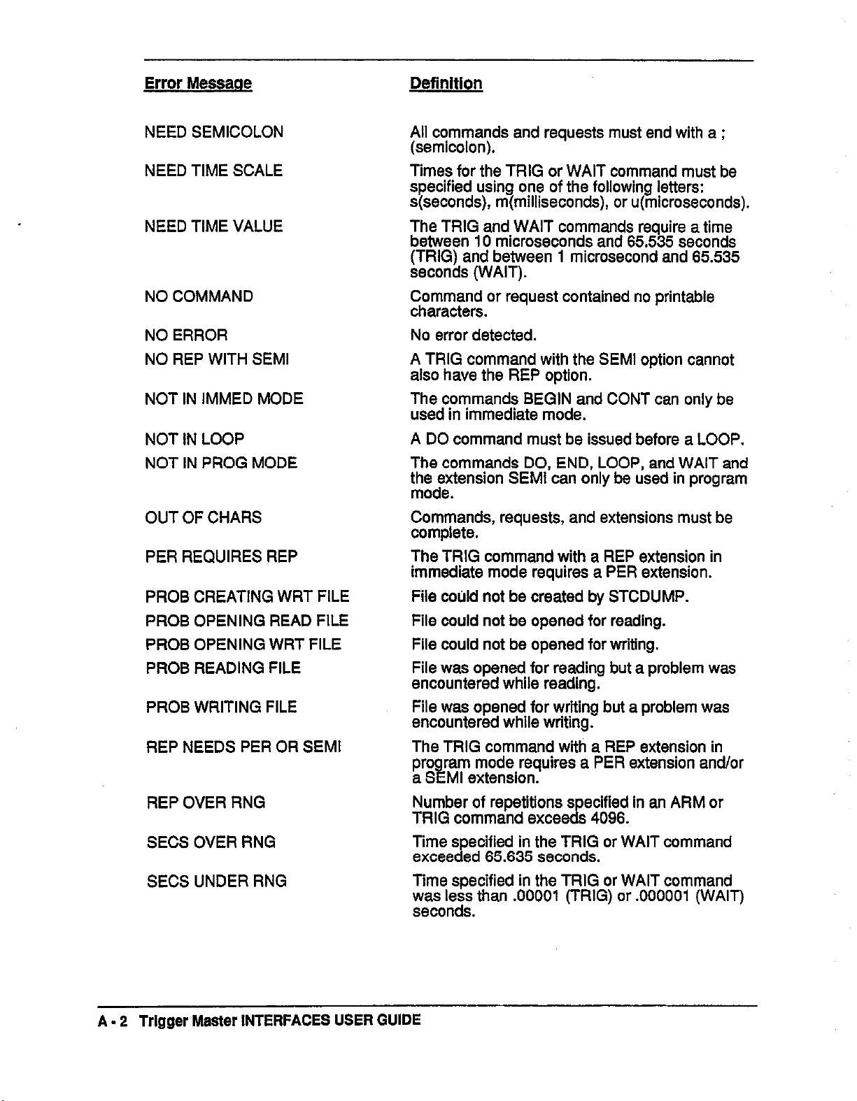
Error Messaoe
NEED SEMICOLON
NEED TIME SCALE
NEED TIME VALUE
NO COMMAND
NO ERROR
NO REP WITH SEMI
NOT IN IMMED MODE
NOT IN LOOP
NOT IN PROG MODE
OUT OF CHARS
All commands and requests must end with a ;
(semicolon).
Times for the TRIG or WAIT command must be
specified using one of the following letters:
s(seconds), m(milliseconds), or u(microseconds).
The TRIG and WAIT commands require a time
between 10 microseconds and 65.535 seconds
(TRIG) and between 1 microsecond and 65.535
seconds (WAIT).
Command or request contained no printable
characters.
No error detected.
A TRIG command with the SEMI option cannot
also have the REP option.
The commands BEGIN and CONT can only be
used in immediate mode.
A DO command must be issued before a LOOP.
The commands DO, END, LOOP, and WAIT and
thh;;tensron SEMI can only be used in program
Commands, requests, and extensions must be
complete.
PER REQUIRES REP
PROB CREATING WRT FILE
PROB OPENING READ FILE
PROB OPENING WRT FILE
PROB READING FILE
PROB WRITING FILE
REP NEEDS PER OR SEMI
REP OVER RNG
SECSOVERRNG
SECS UNDER RNG
The TRIG command with a REP extension in
immediate mode requires a PER extension.
File could not be created by STCDUMP.
File could not be opened for reading.
File could not be opened for writing.
File was opened for reading but a problem was
encountered while reading.
File was opened for writing but a problem was
encountered while writing.
The TRIG command with a REP extension in
pro
ram mode requires a PER extension and/or
a S k
Ml extension.
Number of repetitions s ecified in an ARM or
TRIG command excee CL 4096.
Time specified in the TRIG or WAIT command
exceeded 65.635 seconds.
Time specified in the TRIG or WAIT command
v~w;~lee; than .OOOOl (TRIG) or .OOOOOl (WAIT)
Trigger Master INTERFACES USER GUIDE
A - 2
Page 91
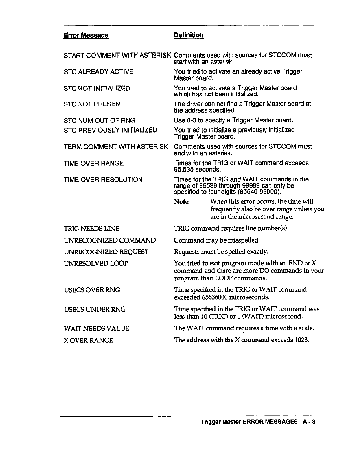
Error Messaae Definition
START COMMENT WITH ASTERISK Comments used with sources for STCCOM must
start with an asterisk.
STC ALREADY ACTIVE
STC NOT INITIALIZED You tried to activate a Trigger Master board
STC NOT PRESENT
STC NUM OUT OF RNG
STC PREVIOUSLY INITIALIZED
TERM COMMENT WITH ASTERISK
TIME OVER RANGE
TIME OVER RESOLUTION
You tried to activate an already active Trigger
Master board.
which has not been initialized.
The driver can not find a Trigger Master board at
the address specified.
Use O-3 to specify a Trigger Master board.
You tried to initialize a previously initialized
Trigger Master board.
Comments used with sources for STCCOM must
end with an asterisk.
Times for the TRIG or WAIT command exceeds
65.535
Times for the TRIG and WAIT commands in the
range of 65536 through 99999 can only be
specified to four digits (65540-99990).
Note:
seconds.
When this error occurs, the lime will
frequently also be over range unless you
are in the microsecond range.
TRlG NEEDS LINE
TRIG command requires line number(s).
UNRECOGNIZED COMMAND
UNRECOGNIZED REQUEST
UNRESOLVED LOOP
Command may be misspelkd.
Requests must be spelled exactly.
You tried to exit program mode with an END or X
command and there are more DO commands ln your
program than LOOP commands.
USECS OVER RNG
Time specified ln the TRIG or WAIT command
exceeded 65636000 microseconds.
USECS UNDER RNG
Time specified in the TRIG or WAIT command was
less than 10 (TRIG) or 1 (WAIT) microsecond.
WAIT NEEDS VALUE The WAIT co
X OVER RANGE
The address with the X command exceeds 1023.
mmand requires a lime with a scale.
Trigger Master ERROR MESSAGES
A - 3
Page 92

Page 93

This appendix contains examples for the structure of the strings required by STCCMD to
accomplish various tasks. Refer to Chapter 3 for a complete discussion of the strings; see
Appendix A for a list of error messages returned by the calls.
B.l GENERATE TRIGGER OUTPUTS
The following examples generate trigger outputs (Active low pulse, 5us long).
.
Generate a trigger on lines 1,2 and 5:
trig
L2,Si
Note: Separate multiple line numbers with commas.
. Generate five triggers, 15 milliseconds apart on line 2:
Appendix 6
COMMAND QUICK START
erig 2:rep siper 1510;
Note: Use sfseconds), mkmlliseconds) or uknicroseconds) to designate time
scales.
. Generate two triggers on line 6 in the semi-sync mode:
erig s:re.p 2*smi,
Note: Use semi-sync in program mode only.
8.2 WAIT FOR TRIGGER INPUTS
The following examples generate a wait for trigger inputs condition.
. Wait for high-to-low triggers on lines 1,4 and 5:
arm 1,d.S;
Note: Separate multiple line numbers with co-s.
. Wait for low-to-high trigger on line 6.
am s+;
. Wait for seven repetitions of high-to-low triggers on line 2:
am 2:rep7;
Note: Use in program mode only.
COMMAND QUICK START B - 1
Page 94

8.3
ENTER PROGRAM MODE
The following examples enter program mode.
.
Put Trigger Master in program mode and start program execution at location 0:
begin;
. Put Trigger Master in program mode and start program execution at location 24:
begin 24;
B.4
B.5
B.6
SET UP and TERMINATE PROGRAM LOOP (Program Mode Only)
The following examples set up and terminate a program loop:
. Start loop of 45 repetitions:
de 4s;
. Terminate loop:
lOoPi
GENERATE A WAIT (Program Mode Only)
The following example generates a wait condition.
. Generate a wait of 3.22 seconds:
wait 3.22?3;
Note: Use s(seconds), mfmilliseconds) or u(rnicroseconds) to designate time
scales.
TRACK PROGRAM EXfXXJTlON and GENERATE INTERRUPTS
The following examples track program execution and generate an mterrupt.
. Write 76 into the flag register:
flag 76;
Note: Use the flag request to read the flag register.
.
Write 36 to the flag register, generate an interrupt, and halt the program:
flag 36rint;
Note: Programs using :rm should be started with XIINT and continued with cow~:r.m.
Trigger Master INTERFACES USER GUIDE
B - 2
Page 95
B.7
EXIT PROGRAM MODE
The following example exits program mode.
. Exit program mode:
ena;
8.6
8.9
INITIATE PROGRAM EXECUTION
The following examples start program execution.
. Start program execution at location 0:
Xi
Note:
If the program contains the command BL~C~~I :rter, use X:INT.
. Start program execution at location 300:
I 300;
Note:
If the program contains the command PLILG~LUL~ :IW, use x XKI:IX
HALT Trigger Master EXECUTION
The following example halts program
m Halt Trigger Master program execution:
bdt;
Note: You can
use
this
command in immediate mode or insert it within a
program. When you insert the command in a program, restart the
program with the command COW from immediate mode.
execution
on Trigger Master.
B-10
CONTINUE EXECUTION of HALTED PROGRAM
The following example continues execution of a halted program.
Continue
.
cant ,
Note:
execution
of halted program:
If the program contains the command sm~tpnl :rxr, use CONT:INT.
COMMAND QUICK START S - 3
Page 96

Page 97

Appendix C
REQUEST QUICK START
This appendix presents examples for the content of strings required by STCSTAT to
make various requests. Refer to Chapter 3 for a complete discussion of the strings; see
Appendix A for a list of error messages returned by the calIs.
C.l Check Remaining Trigger Inputs Established by ARM Command
The following example checks any remaining trigger inputs established by the ARM
command.
. Determine if Trigger Master is waiting for trigger inputs:
alm:*eP;
C.2 Check Remainlng Trigger Outputs Established by TRIG Command
The following example checks for remainin
command.
. Determine if Trigger Master is outputting triggers:
trig:rep;
g trigger outputs established by the TRIG
C-3 Check the Actual Btate of the Trigger Lines
The following example checks the actual state of the trigger lines. This command is
useful for hardware debugging purposes if the trigger detect circuitry uses latched
edges.
. Check the state of the trigger lines:
tris:in;
C.4 Check Time Remaining Before Next Trigger
The following example checks the time remaining before the next trigger.
. Check the remaining time:
trig:per;
Note: After executing the trigger, the time is reset to the initial period. Use one of the
following commands to determine what is happening: PLP.~, TP.IW.SP, ST~VOEI, or
CONT.
REQUEST QUICK START C - 1
Page 98

C.5 Check Program Progress
The following examples check the progress of the program.
, Check for program stiIl running:
staeurr;
Note: Bit 0 (the lowest bit) is set during program execution.
Check memory location of next instruction to execute:
.
eont i
. Check value of flag register that can be updated during program execution to
determine location in program:
flagi
Check if program has generated interrupt:
.
*tAtus;
Note: Bit 3 is set during interrupt request.
C.6 Check Remaining Loop Count
The following example checks the remaining loop count.
. Check progress through current loop:
1-R;
If program is in nested loop, check count remaining in outer loop:
.
loop:oUtl
Note: This command is meaningful only within an executing nested loop.
C.7 Check Remaining Delay lime
The following example checks the remaining delay time.
Check remaining delay time:
.
wait1
Note: After a delay, the time is reset to the initial delay time. Use a COWJ oz BLAT
=e~~t to determine if you are beyond a wait instruction.
C - 2 Trigger Master INTERFACES USER GUIDE
 Loading...