

Page 1

TX-DMM TX1 and TX3
True RMS Digital Multimeters
User Manual
070-9880-01
*P070988001*
070988001
Page 2

Copyright © T ektronix, Inc. All rights reserved. Licensed software products
are owned by T ektronix or its suppliers and are protected by United States
copyright laws and international treaty provisions.
Use, duplication, or disclosure by the Government is subject to restrictions as
set forth in subparagraph (c)(1)(ii) of the Rights in T echnical Data and
Computer Software clause at DF ARS 252.227-7013, or subparagraphs (c)(1)
and (2) of the Commercial Computer Software – Restricted Rights clause at
F AR 52.227-19, as applicable.
T ektronix products are covered by U.S. and foreign patents, issued and
pending. Information in this publication supercedes that in all previously
published material. Specifications and price change privileges reserved.
T ektronix, Inc., P.O. Box 500, Beaverton, OR 97077-1000
TEKTRONIX and TEK are registered trademarks of T ektronix, Inc.
Page 3

WARRANTY
Tektronix warrants that the products that it manufactures and sells will be free from defects
in materials and workmanship for a period of three (3) years from the date of shipment. If a
product proves defective during this warranty period, Tektronix, at its option, either will
repair the defective product without charge for parts and labor, or will provide a
replacement in exchange for the defective product.
In order to obtain service under this warranty, Customer must notify Tektronix of the
defect before the expiration of the warranty period and make suitable arrangements for the
performance of service. Customer shall be responsible for packaging and shipping the
defective product to the service center designated by Tektronix, with shipping charges
prepaid. Tektronix shall pay for the return of the product to Customer if the shipment is to
a location within the country in which the Tektronix service center is located. Customer
shall be responsible for paying all shipping charges, duties, taxes, and any other charges for
products returned to any other locations.
This warranty shall not apply to any defect, failure or damage caused by improper use or
improper or inadequate maintenance and care. Tektronix shall not be obligated to furnish
service under this warranty a) to repair damage resulting from attempts by personnel other
than Tektronix representatives to install, repair or service the product; b) to repair damage
resulting from improper use or connection to incompatible equipment; c) to repair any
damage or malfunction caused by the use of non-Tektronix supplies; or d) to service a
product that has been modified or integrated with other products when the effect of such
modification or integration increases the time or difficulty of servicing the product.
THIS WARRANTY IS GIVEN BY TEKTRONIX IN LIEU OF ANY OTHER
WARRANTIES, EXPRESS OR IMPLIED. TEKTRONIX AND ITS VENDORS
DISCLAIM ANY IMPLIED WARRANTIES OF MERCHANTABILITY OR
FITNESS FOR A PARTICULAR PURPOSE. TEKTRONIX’ RESPONSIBILITY
TO REPAIR OR REPLACE DEFECTIVE PRODUCTS IS THE SOLE AND
EXCLUSIVE REMEDY PROVIDED TO THE CUSTOMER FOR BREACH OF
THIS WARRANTY. TEKTRONIX AND ITS VENDORS WILL NOT BE LIABLE
FOR ANY INDIRECT, SPECIAL, INCIDENTAL, OR CONSEQUENTIAL
DAMAGES IRRESPECTIVE OF WHETHER TEKTRONIX OR THE VENDOR
HAS ADVANCE NOTICE OF THE POSSIBILITY OF SUCH DAMAGES.
Page 4

Contacting Tektronix
Product
support
Service
support
For other
information
To write us
Web site
For questions about using T ektronix measurement
products, call toll free in North America:
1-800-833–9200
6:00 a.m. – 5:00 p.m. Pacific time
Or contact us by e-mail:
tm_app_supp@tek.com
For product support outside of North America,
contact your local T ektronix distributor or sales
office.
T ektronix offers extended warranty and calibration
programs as options on many products. Contact
your local T ektronix distributor or sales office.
For a listing of worldwide service centers, visit our
web site.
In North America:
1-800–833–9200
An operator can direct your call.
Tektronix, Inc.
P.O. Box 500
Beaverton, OR 97077-1000
USA
www .tektronix.com
Page 5

Table of Contents
General Safety Summary iii. . . . . . . . . . . . . . . . . . . . . . . . . . . .
Front and Rear Panel Overview 1. . . . . . . . . . . . . . . . . . . . . . .
Display Indicators 3. . . . . . . . . . . . . . . . . . . . . . . . . . . . . . . . . . .
Measurement Function Knob 4. . . . . . . . . . . . . . . . . . . . . . . . . .
Input Connectors 5. . . . . . . . . . . . . . . . . . . . . . . . . . . . . . . . . . . .
Operating Basics 6. . . . . . . . . . . . . . . . . . . . . . . . . . . . . . . . . . .
Safe Test Lead Connections 6. . . . . . . . . . . . . . . . . . . . . . . . . . . .
Using Procedures in this Section 7. . . . . . . . . . . . . . . . . . . . . . . .
Voltage Measurements 8. . . . . . . . . . . . . . . . . . . . . . . . . . . . . . . .
Application: Using AC DC and AC+DC in Volts Mode 9. .
dB and dBm Voltage Measurements 10. . . . . . . . . . . . . . . . . . . . .
Application: Using a Reference Value Other than
Default 1.000 VRMS in dB Mode 10. . . . . . . . . . . . . . . . .
Application: Using Voltage in a Circuit as the
Reference Value in dB Mode 11. . . . . . . . . . . . . . . . . . . . .
Frequency Measurements 12. . . . . . . . . . . . . . . . . . . . . . . . . . . . .
Negative Edge Triggering 12. . . . . . . . . . . . . . . . . . . . . . . . . .
Positive and Negative Duty Factor 12. . . . . . . . . . . . . . . . . . .
AC vs. DC Coupled Frequency Measurements 13. . . . . . . . . .
Changing Voltage Range in Frequency Mode 13. . . . . . . . . . .
Resistance Measurements
(Ohms, Continuity, Diode, and 50W Range) 14. . . . . . . . . . . .
Application: Measuring Low Resistance Values 14. . . . . . . . .
Capacitance Measurement 15. . . . . . . . . . . . . . . . . . . . . . . . . . . . .
T emperature Measurements (TX3 only) 16. . . . . . . . . . . . . . . . . .
Helpful Tip: Increased Temperature Accuracy 16. . . . . . . . . .
Current Measurements 18. . . . . . . . . . . . . . . . . . . . . . . . . . . . . . . .
TX1 and TX3 True RMS Digital Multimeters
i
Page 6

T able of Contents
Button and Softkey Overview 19. . . . . . . . . . . . . . . . . . . . . . . . .
Blue Button 19. . . . . . . . . . . . . . . . . . . . . . . . . . . . . . . . . . . . .
RANGE Button 19. . . . . . . . . . . . . . . . . . . . . . . . . . . . . . . . . .
M/M/A (Minimum, Maximum, and A verage) Button 19. . . . .
1ms (1 ms Peak Hold) 20. . . . . . . . . . . . . . . . . . . . . . . . . . . . .
Backlight Button 20. . . . . . . . . . . . . . . . . . . . . . . . . . . . . . . . .
HOLD Button 20. . . . . . . . . . . . . . . . . . . . . . . . . . . . . . . . . . . .
Auto Hold 21. . . . . . . . . . . . . . . . . . . . . . . . . . . . . . . . . . . . . . .
D Button (Making Relative (D DELTA) Measurements) 21. .
MEM (Memory) 22. . . . . . . . . . . . . . . . . . . . . . . . . . . . . . . . . .
Softkeys 23. . . . . . . . . . . . . . . . . . . . . . . . . . . . . . . . . . . . . . . . . . .
Setup Menu 23. . . . . . . . . . . . . . . . . . . . . . . . . . . . . . . . . . . . . . . .
Special Features 25. . . . . . . . . . . . . . . . . . . . . . . . . . . . . . . . . . . .
High Resolution (HrES) 50,000-Count Mode 25. . . . . . . . . . .
Beeper 25. . . . . . . . . . . . . . . . . . . . . . . . . . . . . . . . . . . . . . . . .
Auto-Off 25. . . . . . . . . . . . . . . . . . . . . . . . . . . . . . . . . . . . . . . .
Power-Up Options 26. . . . . . . . . . . . . . . . . . . . . . . . . . . . . . . .
MAX/MIN/AVG Operation 28. . . . . . . . . . . . . . . . . . . . . . . . .
Auto Fuse Detection 29. . . . . . . . . . . . . . . . . . . . . . . . . . . . . .
Specifications 30. . . . . . . . . . . . . . . . . . . . . . . . . . . . . . . . . . . . . .
Accessories 43. . . . . . . . . . . . . . . . . . . . . . . . . . . . . . . . . . . . . . . .
Setup for Optional Computer Interface
Accessory (WSTRM) 45. . . . . . . . . . . . . . . . . . . . . . . . . . . . .
Using Protective Boot and Versa-Stand 46. . . . . . . . . . . . . . .
Battery Replacement 47. . . . . . . . . . . . . . . . . . . . . . . . . . . . . . . .
Servicing TX Series Multimeters 48. . . . . . . . . . . . . . . . . . . . . .
General Care and Cleaning 51. . . . . . . . . . . . . . . . . . . . . . . . . .
Index 52. . . . . . . . . . . . . . . . . . . . . . . . . . . . . . . . . . . . . . . . . . . . .
ii
TX1 and TX3 True RMS Digital Multimeters
Page 7

General Safety Summary
Review the following safety precautions to avoid injury and prevent
damage to this product or any products connected to it. T o avoid
potential hazards, use this product only as specified.
Only qualified personnel should perform service procedures.
To Avoid Fire or Personal Injury
Connect and Disconnect Properly. Do not connect or disconnect probes
or test leads while they are connected to a voltage source.
Observe All Terminal Ratings. To avoid fire or shock hazard, observe all
ratings and markings on the product. Consult the product manual for
further ratings information before making connections to the product.
Do not apply a potential to any terminal, including the common
terminal, that exceeds the maximum rating of that terminal.
Replace Batteries Properly. Replace batteries only with the proper type
and rating specified.
Do Not Operate Without Covers. Do not operate this product with
covers or panels removed.
Use Proper Fuse. Use only the fuse type and rating specified for this
product.
Avoid Exposed Circuitry. Do not touch exposed connections and
components when power is present.
Do Not Operate With Suspected Failures. If you suspect there is damage
to this product, have it inspected by qualified service personnel.
Do Not Operate in Wet/Damp Conditions.
Do Not Operate in an Explosive Atmosphere.
Keep Product Surfaces Clean and Dry.
TX1 and TX3 True RMS Digital Multimeters
iii
Page 8
General Safety Summary
Safety Terms and Symbols
Terms in This Manual. These terms may appear in this manual:
WARNING. Warning statements identify conditions or practices that
could result in injury or loss of life.
CAUTION. Caution statements identify conditions or practices that
could result in damage to this product or other property.
Terms on the Product. These terms may appear on the product:
CAUTION indicates a hazard to property including the product.
Symbols on the Product. These symbols may appear on the product:
WARNING
Risk of
Electric Shock
iv
CAUTION
Refer to Manual
TX1 and TX3 True RMS Digital Multimeters
Double
Insulated
Page 9
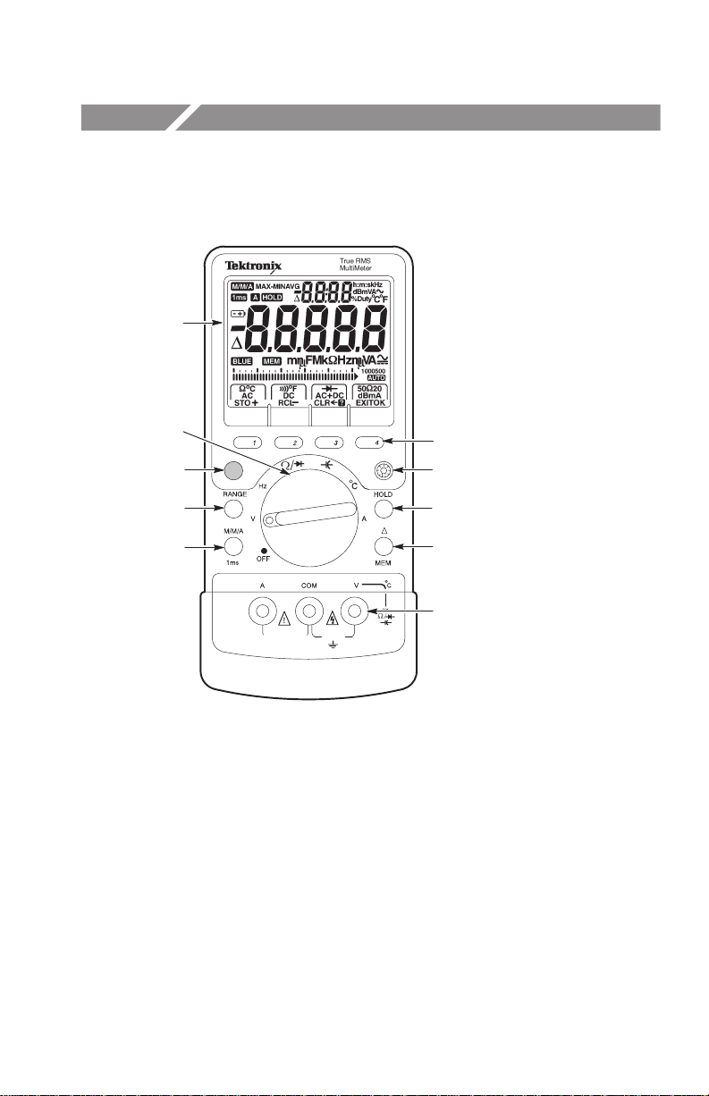
Front and Rear Panel Overview
1
2
3
4
5
6
7
8
9
10
FUSED 600V
15A/30 SECONDS
CATIII
10A
1000V
1 Extra large LCD display with dual numerical readout.
2 Measurement function knob – Use to select a measurement.
Blue Button – Use to access 1ms, MEM, and Setup menu.
3
4 RANGE Button – Use to set measurement range.
5 M/M/A Button – Use to set meter to MIN/MAX/AVG or 1ms modes.
6 Softkeys – Use with measurement function knob to select measurements.
7 Backlight Button – Use to turn backlight on and off.
8 HOLD Button – Use to freeze display.
9 D Button – Use to make relative measurements and access the memory.
10 Input connectors.
TX1 and TX3 True RMS Digital Multimeters
1
Page 10
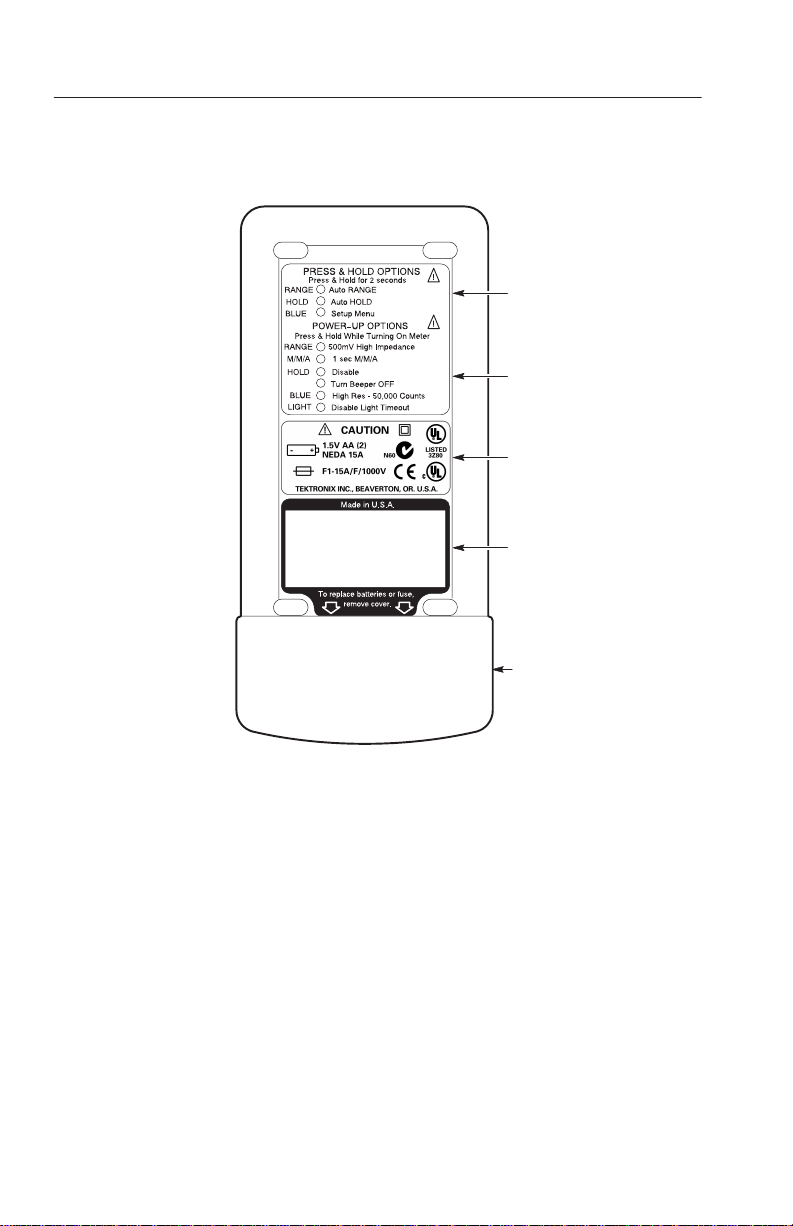
Front and Rear Panel Overview
1
Auto Off
2
3
4
5
1 Press and hold options – Activate by holding down the specified button for two
seconds while the meter is on.
2 Power-up options – Activate by holding down the specified button while turning
on the meter.
3 Compliance and battery and fuse replacement information.
4 Serial number and barcode tag.
5 Removable battery cover.
2
TX1 and TX3 True RMS Digital Multimeters
Page 11
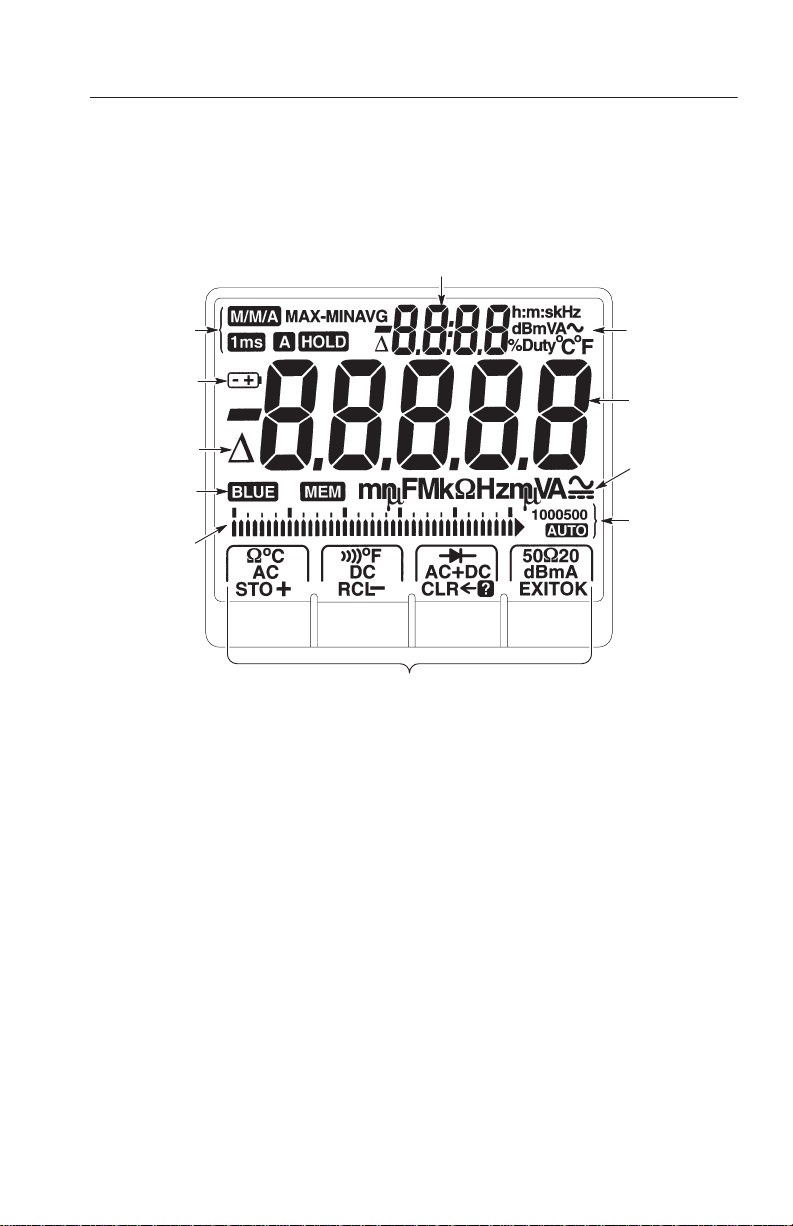
Display Indicators
Front and Rear Panel Overview
6
1
2
3
4
5
1
Special feature indicators
2 Low battery indicator
3 Delta indicator
4 Blue button and memory
mode indicators
5 Bargraph
7
8
9
10
11
6 Upper display
7 Upper display units
8 Main display
9 Main display units
10 Range indicators
11 Softkey menus
TX1 and TX3 True RMS Digital Multimeters
3
Page 12
Front and Rear Panel Overview
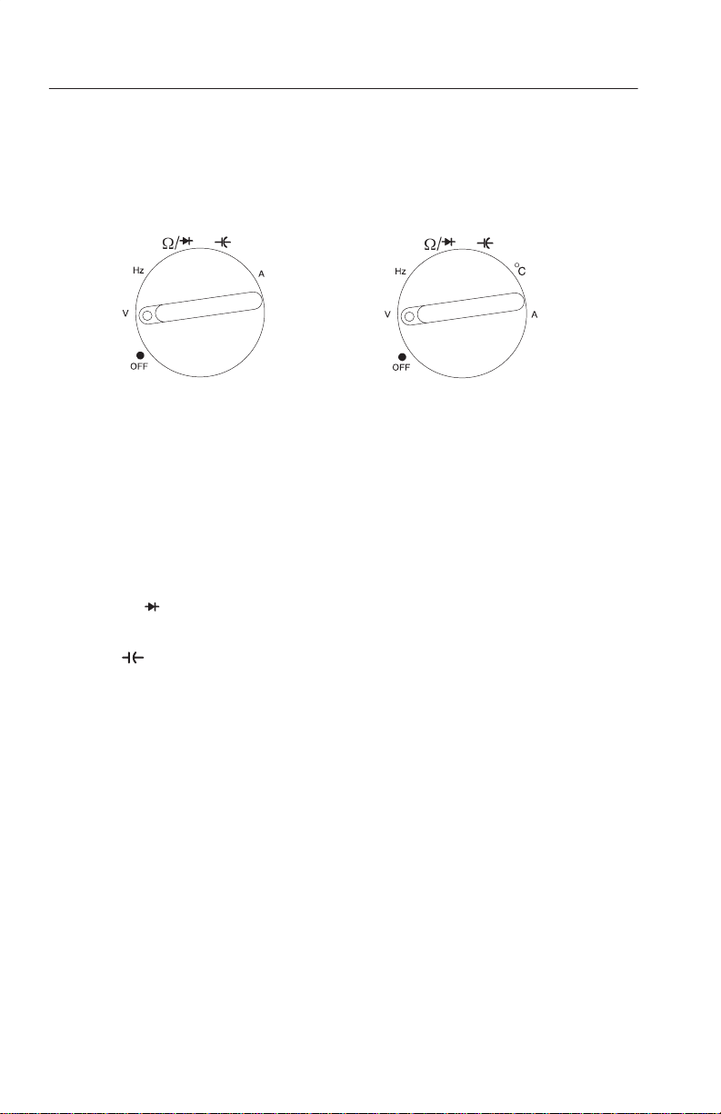
Measurement Function Knob
TX1
TX3
OFF. Turns of f the meter. Setup parameters and stored measurements
are saved.
V. Volts AC RMS, Volts DC, Volts AC DC dual display, Volts
AC+DC total RMS, dB, and dBm.
Hz. Frequency measurements. Duty factor also shows if it is turned
on in the Setup menu.
W/ . Access to resistance and continuity measurements and diode
test.
. Capacitance measurements.
_C. Temperature measurements in degrees Celsius or Fahrenheit.
A. Amps AC RMS, Amps DC, Amps AC + DC total RMS, Amps AC
DC dual display, and Amps DC 4-20 mA% (process control loop
measurement).
4
TX1 and TX3 True RMS Digital Multimeters
Page 13
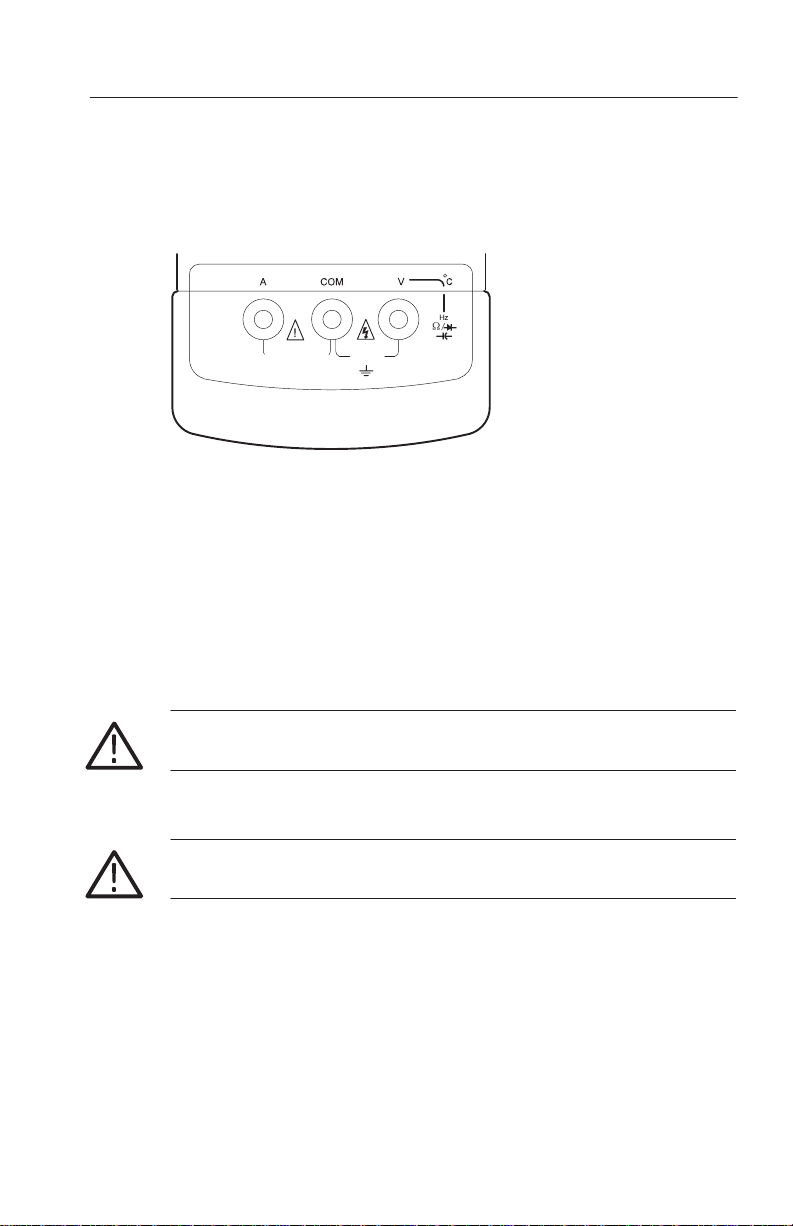
Input Connectors
Front and Rear Panel Overview
FUSED 600V
10A
15A/30 SECONDS
CATIII
1000V
A. Input connector for current measurements up to 10 A (15 A for 30
seconds). Rating is 600 V open circuit voltage.
COM. Common connector. All measurements are referenced to this
connector.
V. Input connector for volts, frequency, ohms, continuity, diode,
capacitance, and temperature measurements. Rating is 1000V
CAT III for all V. input connector measurements.
WARNING. To avoid personal injury, do not attach meter leads with
the battery cover removed.
CAUTION. To avoid damaging the meter, do not attempt to measure
current with the batteries removed.
TX1 and TX3 True RMS Digital Multimeters
5
Page 14

Operating Basics
Before you take any of the measurements described in this section,
follow these steps:
H For specified accuracy, allow the meter to stabilize for 30
seconds after you turn on the meter.
H Observe the safe test lead connections below when you remove
the test leads from the meter.
H Always disconnect power to the circuit when you measure
resistors, capacitors, diodes, or continuity within the circuit.
H Discharge capacitors before taking capacitance measurements.
Safe Test Lead Connections
T o safely disconnect the test leads from the meter, first disconnect all
test leads from the circuit being tested, then disconnect the leads
from the input connectors.
WARNING. To prevent electrical shock, do not insert unnecessary test
leads or metal pins into the A (amps) connector. Voltages applied to
any connector may be present at all other input connectors. Only use
the test leads supplied or recommended (or their equivalent) with the
meter. Refer to Accessories on page 43.
6
TX1 and TX3 True RMS Digital Multimeters
Page 15
Operating Basics
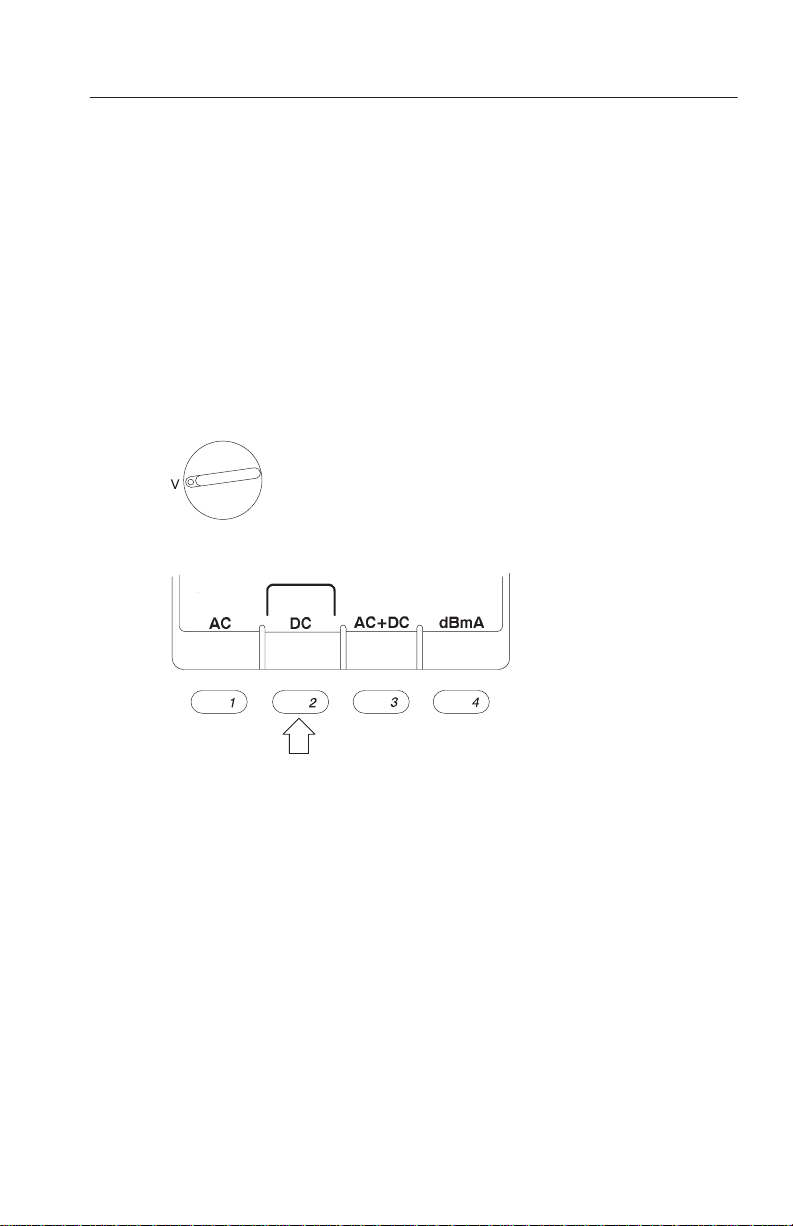
Using Procedures in this Section
All measurements are made by first setting the measurement function
knob to a function setting and then selecting a measurement from the
softkeys. Note that not all knob settings have corresponding softkey
settings.
For example, the steps below show how to make a DC voltage
measurement:
1. Set the measurement function knob to V for a voltage measure-
ment.
2. Select softkey 2 for DC voltage.
3. Connect the leads to the measurement points.
TX1 and TX3 True RMS Digital Multimeters
7
Page 16
Operating Basics
AC DC ( ress
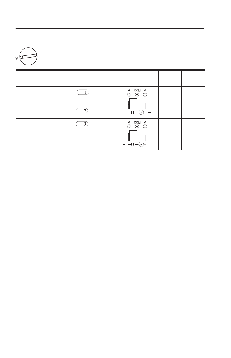
Voltage Measurements
Measurement Softkey Connect leads
True RMS AC voltage
AC
(default)
DC voltage
AC DC dual display
DC
AC DC or
AC+DC (press to
AC+DC total RMS
1
V
+ VAC2) VDC
RMS
1
Ǹ
toggle)
2
Main
display
Upper
display
AC Hz
DC ––
DC AC
AC+DC Hz
8
TX1 and TX3 True RMS Digital Multimeters
Page 17

Operating Basics
Application: Using AC DC and AC+DC in Volts Mode
DC = 5 V
AC = 1V
RMS
Frequency = 60 Hz
AC voltages riding on power supplies can cause problems with
electronic circuits. If you set the meter to DC Volts mode, the display
shows the DC component of 5.000 V. However, the AC component
may be missed. It is recommended that you set the meter to AC DC
dual display mode. The main display shows the 5.000 V DC voltage
and the upper display shows the 1.000 V AC voltage. AC DC mode
also allows you to simultaneously make AC and DC measurements
without changing the meter settings.
Another useful measurement is AC+DC total RMS. T o take this
measurement, press softkey 3 to toggle to AC+DC. In the above
example, the total RMS of 5.099 V shows on the main display and
the frequency of 60.00 Hz shows on the upper display. When
calculating the power dissipated in a circuit component, it is critical
that the DC value is factored into the equation V
V
is AC+DC total RMS.
RMS
TX1 and TX3 True RMS Digital Multimeters
RMS
I
RMS
, where
9
Page 18

Operating Basics
dB and dBm Voltage Measurements
Main
Measurement Softkey Connect leads
dB (TX3 only)
1
dB or dBm
display
AC dB
(press to toggle)
dBm (TX3 only)
1
dB readout = 20 log (main display readout/ref), where ref = 1 V is the default.
2
dBm readout = 10 log (main display readout2/R), where R=600 W.
2
AC dBm
Application: Using a Reference Value Other than Default 1.000 V
in dB Mode
T o manually change the reference voltage in dB mode, press and
hold the blue button to display the Setup menu. Adjust the rEF (dB)
value to the value you want and press softkey 4 for OK. Subsequent
dB measurements will use this stored value as the reference voltage
until you turn off the meter.
Upper
display
RMS
10
TX1 and TX3 True RMS Digital Multimeters
Page 19

Operating Basics
Application: Using Voltage in a Circuit as the Reference Value
in dB Mode
An example of using a voltage in a circuit as the reference value is
measuring the AC voltage gain of an amplifier. Set the meter to dB
mode and measure the voltage that you want to use for the reference
(the input of the amplifier). Press the button to save the measured
value as the reference value. Next, measure the output of the
amplifier. The voltage gain of the amplifier (in dB) shows in the
upper display.
In both of these applications, the indicator shows in the upper
display to indicate the reference is a voltage other than the default
value of 1.000 V
. The reference value returns to 1.000 V when
RMS
you exit dB mode.
TX1 and TX3 True RMS Digital Multimeters
11
Page 20
Operating Basics
(
)
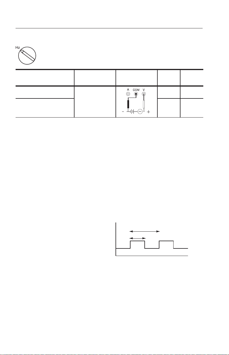
Frequency Measurements
Main
Measurement Softkey Connect leads
Frequency
Frequency and duty factor
dual display
1
Displayed when you set negative edge triggering in the Setup menu. –EdGE is active
but not displayed when % duty is on.
2
You must turn on positive or negative duty in Setup menu.
no selection
display
Hz – EdGE
Hz % Duty
Negative Edge Triggering
To trigger on the negative edge of the waveform, set EdGE to nEG in
the Setup menu. The word -EdGE shows in the upper display when
you exit the Setup menu.
Positive and Negative Duty Factor
T o measure duty factor, set duty (POL in the Setup menu) to either
POS or nEG. When you measure negative duty factor, a “–” symbol
shows in the upper display.
Positive duty factor:
% duty = (a/b) 100
b
a
Upper
display
1
2
Negative duty factor:
% duty = (1–a/b) 100
12
TX1 and TX3 True RMS Digital Multimeters
Page 21

Operating Basics
AC vs. DC Coupled Frequency Measurements
When the duty factor measurement mode is off, the frequency
measurement is AC coupled; otherwise, it is DC coupled.
Changing V oltage Range in Frequency Mode
T o change voltage range, press the RANGE button. The voltage
range shows momentarily in the upper display. Continue pressing the
RANGE button to cycle through the available voltage ranges until
the range you want shows. The default voltage range is 5 V.
TX1 and TX3 True RMS Digital Multimeters
13
Page 22

Operating Basics
Resistance Measurements (Ohms, Continuity, Diode, and 50W Range)
Measurement Softkey Connect leads
Resistance (default)
Continuity
Diode
1
50
1
See application below.
Forward bias
Reverse bias
50
Application: Measuring Low Resistance Values
T o measure low resistance values to 0.01 W resolution, set the meter
to 50 W mode and short the leads together to subtract the lead
resistance. If you do not short the leads together, the meter will not
enter 50 W mode. The lead resistance must be less than 5 W. The
measured resistance shows on the main display.
Main
display
V ––
Upper
display
––
OPEn or
Shrt
(beeps
on short)
––
14
CAUTION. To avoid damaging the meter, remove all power from the
circuit before connecting the test leads.
TX1 and TX3 True RMS Digital Multimeters
Page 23

Capacitance Measurement
Operating Basics
Main
Measurement Softkey Connect leads
Capacitance (no selection) F ––
CAUTION. To avoid damaging the meter, remove all power from the
circuit before connecting the test leads.
Measuring large-value capacitors may take several seconds.
Follow the procedures below when making capacitance measure-
ments:
H Remove capacitors from circuitry.
H Discharge capacitors before measuring them.
H Connect polarized caps as shown above.
H T o measure small values of capacitance accurately, press the
button when the leads are open.
display
Upper
display
TX1 and TX3 True RMS Digital Multimeters
15
Page 24

Operating Basics
C
Ther
e
F
Ther
e
Temperature Measurements (TX3 only)
Measurement Softkey Connect leads
Celsius temperature
(default)
Fahrenheit temperature
°
ATK01
mocoupl
mocoupl
°
probe adapter
ATP01 K-Type
Temperature probe
Before you take a temperature measurement, momentarily change
the temperature of the thermocouple to verify a shorted or open
thermocouple is not incorrectly displaying the ambient temperature.
Helpful Tip: Increased Temperature Accuracy
T o achieve high accuracy temperature measurements to ±1.0 °C it is
necessary to calibrate the meter to account for any thermocouple
offset. Temperature accuracy without performing the following
calibration is ±3 °C:
1. Turn on the meter in the environment you will make the
measurements.
2. Fill a wide, shallow container with ice and water. Stir the ice and
water mixture for two or three minutes to evenly distribute the
temperature of the mixture. Place the container next to the meter
and submerge the tip of the bead probe in the ice and water.
Main
display
Upper
display
°C Ambient
temp. °C
°F Ambient
temp. °F
16
TX1 and TX3 True RMS Digital Multimeters
Page 25

Operating Basics
3. While in °C or °F mode, allow the temperature reading to
stabilize on a value (this value should be very close to 0 °C for
°C mode or 32.0 °F for °F mode). Any deviation from 0 °C or
32 °F represents the thermocouple’s offset.
4. Once the reading stabilizes, press and hold softkey 1 for °C mode
or softkey 2 for °F mode for five seconds until the display shows
0000 or 0032.
This calibrates the meter for the operating environment. shows in
the upper display. If you hear an error beep, the offset is greater than
±5 °C. You can repeat this calibration at any time. To undo this
calibration, return the meter to factory settings by pressing both the
blue button and M/M/A button while powering up the meter (see
T able 2 on page 27).
T o insure accuracy of temperature measurements, you should follow
this procedure when using other K-type thermocouple probes with
the TX Series DMMs because accuracy specifications vary in
different types of probes.
NOTE. Observe proper polarity on the probe adapter and do not
calibrate the offset immediately following high amperage measurements.
TX1 and TX3 True RMS Digital Multimeters
17
Page 26

Operating Basics
AC+DC (press
dC rre
0
Current Measurements
Measurement Softkey Connect leads
True RMS AC Amps
DC Amps
AC
DC
(default)
Amps AC DC dual display
Amps AC+DC total RMS
4-20 mA current %
2
(TX3 only)
1
I
2
4-20 mA measurement is used in process loop calibration.
% = (measured current – 4 mA)/16 mA
Ǹ
+ IAC2) IDC
RMS
AC DC or
1
toggle)
2
mA
2
to
source
When overrange occurs in manual range, the meter will uprange in
order to protect the internal circuitry.
CAUTION. To avoid damaging the meter, limit large current
measurements to 15 A for 30 seconds and allow ten minutes of
cooling between measurements. Do not connect to circuits
with u600 V.
LoadCurrent
Main
display
Upper
display
AC Hz
DC ––
DC AC
AC+DC Hz
DC %
18
Do not attempt to measure current with batteries removed.
When you exit current measurement mode, the words CHEC ProbE
show on the display reminding you to remove your test lead from the
A (amps) input connector.
When you make high current measurements, u15 A, use a current
clamp probe (optional accessory) connected to the volts input
connector.
TX1 and TX3 True RMS Digital Multimeters
Page 27

Button and Softkey Overview
Blue Button
T o access functions in blue text, press the blue button and then press
a function button while the indicator is on. The indicator
shows on the display for five seconds.
Press and hold the blue button for two seconds to access the Setup
menu. See page 23 for more information about the Setup menu.
RANGE Button
Use the RANGE button to manually select a range. Press and hold
RANGE for two seconds to return the multimeter to auto range
mode. The meter is in auto range mode when the
on.
indicator is
The range and units are displayed above the
right of the bargraph.
M/M/A (Minimum, Maximum, and Average) Button
Press this button to scroll through the live, maximum, minimum,
maximum–minimum, and average value. The elapsed time between
the last recorded event and the start of the test shows in the upper
display .
Press and hold the M/M/A button for two seconds to exit M/M/A
mode.
See MAX/MIN/AVG Operation on page 28 for more information.
TX1 and TX3 True RMS Digital Multimeters
indicator, to the
19
Page 28

Button and Softkey Overview
1ms (1 ms Peak Hold)
To activate 1 ms peak hold, first press the blue button and then the
M/M/A button while the indicator shows on the display. When
in 1 ms mode, the LCD displays the
Display resolution in 1ms peak hold is 5,000 counts. Live and
average (AVG) readings are not available in 1ms peak hold mode.
You can use 1ms peak hold when you take AC or DC measurements.
The meter only records events that have a pulse width that is greater
than 1 ms.
Press the M/M/A button to view 1ms peak hold minimum and
maximum values. The MAX value shown is the value of the positive
peaks and the MIN value shown is the value of the negative peaks.
Press and hold the M/M/A button for two seconds to exit 1ms peak
hold mode.
Backlight Button
Press the
button to turn the backlight on or off. Adjust the LOFF
setting in the Setup menu to adjust the backlight timeout setting. Use
the Setup menu information on page 23 to adjust the setting for the
backlight.
1ms
and indicators.
20
HOLD Button
Press HOLD to turn hold mode on and off. When you activate the
hold feature, the instrument beeps, freezes the display, and displays
the indicator. Hold mode freezes the display so you can
remove the probes from the test points without losing the measurement reading.
TX1 and TX3 True RMS Digital Multimeters
Page 29

Button and Softkey Overview
Auto Hold
To activate auto hold, press down on the HOLD button until
A
appears on the display. Auto hold is not available for capacitance or
AC DC measurements.
In auto hold mode the display automatically freezes and the
instrument beeps when the measurement reading stabilizes. The
displayed value will be updated when the meter stabilizes on a new
measurement value.
Auto hold is useful when it is not possible for you to press the HOLD
button or see the meter display while probing and taking measurements.
D Button (Making Relative (D DELTA) Measurements)
Use this button to set the meter to delta mode and make relative
measurements. The reference value for the measurement can be a
measured, a stored, or a programmed value.
D Relative to a Measured Value. When you take the measurement and
the meter settles on the measurement value, press the button.
For subsequent readouts, the measured reference value is subtracted
from the actual measurement.
D Relative to a Saved Value. Use the measurement function knob and
softkeys to set the meter to the measurement function you want. Use
the memory information on page 22 to recall (RCL) a reference
value from memory, then press the button. To exit delta mode,
press the button.
For subsequent readouts, the recalled reference value is subtracted
from the actual measurement.
TX1 and TX3 True RMS Digital Multimeters
21
Page 30

Button and Softkey Overview
D Relative to a Programmed Value. Use the measurement function knob
and softkeys to set the meter to the measurement function and range
you want and then press the button. While the meter is in delta
mode, press and hold the blue button until the Setup menu appears.
Use the softkeys to edit rEF to the desired value and press softkey 4
for OK. T o exit delta mode, press the button.
For subsequent readouts the programmed reference value is
subtracted from the actual measurement. The programmed reference
value is lost when you turn off the meter.
You can also use the button to make relative dB (dB) measurements. See page 10 for more information.
MEM (Memory)
Use the memory mode to store and recall measurement values. No
data is lost during power cycles.
T o activate the MEM (memory) mode, press the blue button and then
the button while
shows four softkey selections: STO, RCL, CLR, and EXIT.
shows on the LCD display. The display
22
STO. Select STO to store the held value in the next available memory
location. The memory location number momentarily shows on the
upper display . If no memory locations are available, FULL shows on
the upper display for two seconds and nothing is stored.
T o overwrite an existing memory value, recall the memory location
using the RCL button, press CLR, then press STO to store the new
value in this location.
TX1 and TX3 True RMS Digital Multimeters
Page 31

Softkeys
Button and Softkey Overview
RCL. Select RCL to scroll through the stored values in reverse order.
The upper display momentarily shows the memory location while the
main display shows the value stored in that location.
CLR. Select CLR to clear the currently selected memory location.
The location is replaced with “-----”.
T o clear all memory locations, press and hold the CLR button for
five seconds. A
The word donE shows on the display indicating that all memory
locations are clear and you can release the button. If you release the
button before the word donE shows, no data is cleared from the
memory .
EXIT. Select EXIT to exit memory mode. You can also exit memory
mode by pressing any button.
Each setting on the measurement function knob may activate one or
more softkey settings on the LCD. If there is more than one
measurement for a function knob setting, a softkey menu appears on
the display . Press the corresponding softkey to select the desired
measurement.
?
shows on the display next to the CLR enunciator.
Setup Menu
The Setup menu allows you to customize default settings. T o activate
the Setup menu, press and hold the blue button for two seconds.
Use the softkeys as shown in the following table to edit setup values.
Setup menu values are saved when you turn off the meter, except for
reference values.
TX1 and TX3 True RMS Digital Multimeters
23
Page 32

Button and Softkey Overview
Softkey
Function Press to increase
+
setting value.
–
Press to decrease setting
value.
←
Press to step to
next digit in setting value.
Press to save
setting and move
to next setup parameter.
The following table lists the setup menu prompts, the definition of
parameters, and default values.
Table 1: Setup prompts, definitions, and default values
Upper display
prompt
POFF Sets auto-off time (in minutes). 30 minutes
LOFF Sets backlight auto-off time (in seconds). 60 seconds
bEEP Toggles beeper on and off. ON
HrES Changes display to 50,000 counts. OFF
POL (Duty) Scrolls through OFF, POS (positive duty factor), and
EdGE (Hz) Toggles between POS (positive edge) and NEG
1
rEF
(D)rEF(dB)
1
Meter must be in D or dB mode to access these setup parameters.
Definition of parameter
(press OK to cycle through parameters)
NEG (negative duty factor).
(negative edge) triggering in Hz measurement.
Changes the reference value for delta measure-
ments.
1
Changes the reference value for dB measurements. 1 V
Default
value
OFF
Positive (rising)
Value before
button is pressed
OK
24
TX1 and TX3 True RMS Digital Multimeters
Page 33

Special Features
High Resolution (HrES) 50,000-Count Mode
By default, the meter is set to 5,000-count mode. For 50,000-count
mode, press the blue button when you turn on the meter. To change
the default resolution to 50,000-count mode, use the Setup menu
information on page 23.
The following measurements are limited to 5,000-count mode: 50 W,
50 MW, 1 ms peak hold, AC + DC amps, AC DC amps, AC + DC
volts, AC DC volts, capacitance, and Hertz dual display mode.
Beeper
A single beep indicates correct operation. You can turn the
single-beep feature off in the Setup menu. A double beep indicates a
warning or error condition. A triple beep indicates the meter will
auto-off in one minute. Continuous beeping indicates there is circuit
continuity while in continuity mode. You can not disable double,
triple, or continuous beeps.
Auto-Off
The auto-off feature automatically turns off the meter if no controls
or settings are changed within a set amount of time. T o turn on the
meter after auto-off, press any button. The meter will return to the
state it was in before auto-off occurred, but held values are lost.
Use the Setup menu to adjust the auto-off delay. The default auto-off
time is thirty minutes. You can disable auto-off by pressing the
button when you turn on the meter or by using the Setup
menu.
Auto-off is disabled during M/M/A mode.
TX1 and TX3 True RMS Digital Multimeters
25
Page 34

Special Features
Power-Up Options
T o activate power-up functions, press and hold a button or softkey
when you turn on the meter. Hold the button or softkey until you
hear a single beep and see a text acknowledgment on the display (see
T able 2 below). The following table lists all power-up options. Most
of the power-up option descriptions also appear on the rear panel.
When you turn off the meter, the power-up options are not saved.
Use the Setup menu to change default settings.
Table 2: Power-up options
Button Power-up function Explanation
RANGE
(HI W mV)
Sets meter to 500 mV
1
high impedance mode
Enables high impedance (> 10 MW) across the
input jacks in the 500 mV DC range so that the
device under test is not loaded when you
measure small voltages.
M/M/A
(1 SEC)
D
(bEEP)
BLUE
(HrES)
LIGHT
(LOFF)
Softkey 1 Displays software version
Sets meter to 1 second
1
M/M/A mode
See MAX/MIN/AVG Operation on page 28 for
more information.
Turns off beeper Double, triple, and continuity beeps are not
1
Sets meter to high resolu-
1
tion (50,000 count) mode
Disables light timeout ––
1
affected.
See High Resolution (HrES) 50,000-Count
Mode on page 25 for further information.
Displays the software version (M.mm, where M
and calibration date
is the major revision and mm is the minor
revision). Press softkey 1 again to display the
date the meter was last calibrated (upper
display shows month and main display shows
year).
26
TX1 and TX3 True RMS Digital Multimeters
Page 35

Special Features
Table 2: Power-up options
(Cont.)
Button ExplanationPower-up function
Softkey 2 Overall Diagnostics Displays all LCD segments. Press softkey 2
again to hear the beeper. Press softkey 2 again
to perform button and knob diagnostics. The
display shows two two-digit numbers. The
numbers on the left confirm the knob location
and the numbers on the right confirm the button
operation. To exit diagnostics, turn off meter.
Softkey 3 LCD test Displays all LCD segments so you can verify
correct LCD operation and display. Compare
this to the LCD figure on page 3.
Softkey 4 Battery test Displays the voltage across the battery
terminals. The meter will shut off at 1.5 V.
HOLD
(POFF)
BLUE and
M/M/A
Disables auto-off ––
1
Resets meter to factory
default settings
You must press both buttons at the same time
while powering on the meter.
(rESEt)
1
The bolded text in parentheses in the Button column shows when the meter registers
the power-up setting. Do not release the button until you either hear a single beep
or see the text.
TX1 and TX3 True RMS Digital Multimeters
27
Page 36

Special Features
MAX/MIN/A VG Operation
Press the M/M/A button to start recording M/M/A values. In 5,000
count mode the M/M/A default recording rate is 4 measurements per
second. Press and hold the M/M/A button when turning on the meter
to apply averaging, which reduces the recording rate to 1 measurement per second (1 sec M/M/A).
The M/M/A button cycles through the operations listed in the
following table.
Table 3: MIN/MAX/AVG operations
Display
indicator
MAX The MAX indicator and maximum value are shown. The upper display shows
MIN The MIN indicator and minimum value are shown. The upper display shows
MAX–MIN The MAX–MIN indicator and maximum value minus minimum value are
AVG The AVG indicator is shown and the value shown is the average value of all
Description
The live signal value is shown. The upper display shows the elapsed time
since the recording began.
the timestamp at which the maximum value occurred, relative to the start of
the test.
the timestamp at which the minimum value occurred, relative to the start of the
test.
shown. The upper display shows the time difference between the MAX and
MIN events.
meter readings. The upper display shows the elapsed time since recording
began.
28
TX1 and TX3 True RMS Digital Multimeters
Page 37

Special Features
Once you set the meter to M/M/A mode, the meter will uprange, or
automatically increase range setting, but will not downrange. You
must exit M/M/A mode to restore downranging abilities to the meter.
While in M/M/A mode, press the HOLD button to stop the recording
and freeze the most recent M/M/A values. Press the M/M/A button to
cycle through the held values. Press the HOLD button a second time
to reset and restart the M/M/A recording.
While in M/M/A mode, activate memory mode to hold the displayed
M/M/A value for storage into memory without stopping or resetting
the M/M/A recording.
T o exit M/M/A mode and clear stored values, press and hold the
M/M/A button for two seconds.
Auto Fuse Detection
The meter automatically verifies the integrity of the internal fuse
when you set the measurement function knob to A. If an open fuse is
detected, the word FUSE shows on the main display .
See page 48 for instructions on how to replace fuse F1.
TX1 and TX3 True RMS Digital Multimeters
29
Page 38

Specifications
All specifications are warranted, unless noted as typical, for the rated
temperature range of 23_ C ± 5_ C at less than 80% relative
humidity .
Characteristics Description
LCD display digits
Display counts 5,000 (default) or 50,000
Bargraph 20 segment, updated 20 times per second
Memory locations TX1: 10, TX3: 30
Out of range indicator OL: overrange
Low voltage indicator Battery symbol shows on LCD at 2.0 V.
Battery life 100 hours continuous use with backlight off
Auto-off Adjustable, 30 minute default
Power source Two AA 1.5 V alkaline batteries (NEDA 15A)
Maximum input voltage between
terminals and between terminals
and earth
Maximum open circuit voltage
when utilizing the A terminal
Overload protection, V terminal 1000 V
F1 fuse protection 15 A (1000 V) service-replaceable
Backlight Green LEDs
1
If meter is exposed to water, have it inspected by qualified service
personnel.
@
4
3
(default) or 4
5
@
4
5
Ur: underrange
Meter powers down at 1.5 V.
(typical)
1000 V
(CAT III)
600 V
Installation Category III
RMS
1
CAT III
RMS
(1500 Vpk) for all functions
RMS
30
TX1 and TX3 True RMS Digital Multimeters
Page 39

Table 4: DC voltage characteristics
)
Characteristic Description
Settling time 3 readings (typical)
Reading rate 5,000 ct.: 4 readings per second
50,000 ct.: 1 reading per second
Rejection ratio
Common mode 120 dB at DC or 50 Hz or 60 Hz
Normal mode 60 dB at 50 Hz or 60 Hz
Input impedance
10 MW (typical)
Table 5: DC voltage range, resolution, and accuracy
Specifications
1
Range
0.5 V
5,000 counts
100 mV 10 mV
5 V 1 mV
Resolution Accuracy
50,000 counts TX1 TX3
±(0.07% + 1 count)±(0.05% + 1 count
100 mV
50 V 10 mV 1 mV
500 V 100 mV 10 mV
1000 V 1 V 100 mV
Temperature coefficient Add (0.005% + 0.1 ct.)/°C to accuracy beyond rated
temperature range.
1
Accuracy in 50,000-count mode is % + 10 counts.
TX1 and TX3 True RMS Digital Multimeters
31
Page 40

Specifications
Table 6: AC voltage characteristics
Characteristic Description
Input impedance
10 M in parallel with 100 pF (typical)
Settling time 4 readings (typical)
Reading rate 5,000 ct.: 4 readings per second
50,000 ct.: 1 reading per second
Common mode
60 dB at DC to 60 Hz
rejection ratio
Crest factor, maximum Full scale: 3
Half scale: 6
AC+DC1 total RMS volts
AC (RMS) accuracy + 0.1% + 1 count
accuracy
AC DC1 dual display
accuracy
DC Accuracy + 0.05% + 1 count
AC RMS Accuracy + 0.1% + 1 count
Upper display frequency (5,000 counts)
Accuracy ±(0.002% + 1 count) for 20 Hz to 20 kHz
Sensitivity 10% of selected voltage range
dB reference
dBm reference
1
2
2
2
5,000-count mode only.
See page 10 for dB and dBm calculations.
1 V
(adjustable)
RMS
775 mV across 600 (1 mW)
32
TX1 and TX3 True RMS Digital Multimeters
Page 41

Table 7: AC voltage range, resolution, and accuracy
s)
Specifications
1
40 Hz – 20 kHz:
Range
0.5 V
5,000 counts
100 V 10 V
5 V 1 mV
Resolution Accuracy
50,000 counts TX1 TX3
40 Hz – 20 kHz:
100 V
±(0.6% + 2 counts)±(0.4% + 2 count
50 V 10 mV 1 mV
500 V2100 mV 10 mV
1000 V21 V 100 mV 40 Hz – 10 kHz:
± (0.6% + 2 counts)
40 Hz – 10 kHz:
± (0.4% + 2 counts)
Temperature coefficient AC: Add (0.03% + 0.1 ct.)/°C beyond rated temperature
range.
AC+DC: Add (0.06% + 0.1 ct.)/°C beyond rated temperature
range.
1
Accuracy in 50,000-count mode is % + 20 counts.
2
For voltages 100 V, the maximum volts–Hz product is 10 MVHz.
TX1 and TX3 True RMS Digital Multimeters
33
Page 42

Specifications
s)
Table 8: DC current characteristics
Characteristics Description
Burden voltage 5 mA to 5 A: 0.3 V max.
10 A: 0.5 V max.
Percent 4-20 mA
(calculated in
4 mA = 0%
20 mA = 100%
50 mA range)
Settling time 4 readings (typical)
Reading rate 5,000 ct.: 4 readings per second
50,000 ct.: 1 reading per second
Table 9: DC current range, resolution, and accuracy
Resolution Accuracy
Range
500 A
5 mA
50 mA
500 mA
5 A 1 mA
10 A
5,000 counts
50,000 counts TX1 TX3
100 nA 10 nA ± (0.2% + 4 counts)
1 A
100 nA
±(0.2% + 2 count
10 A 1 A
100 A 10 A
100 A
± (0.4% + 2 counts)
10 mA 1 mA ± (0.8% + 2 counts)
1
2
2
2
(15 A for
30 sec.)
Temperature coefficient Add (0.05% + 0.1 ct.)/°C beyond rated temperature range.
1
Accuracy in 50,000-count mode is % + 40 counts.
2
Accuracy in 50,000-count mode is % + 20 counts.
34
TX1 and TX3 True RMS Digital Multimeters
Page 43

Table 10: AC current characteristics
s)
1
s)
1 (1 0 s)
± (2.0
s)
Characteristics Description
Burden voltage 0.5 mA to 5 A: 0.9 V max.
10 A: 1.0 V max.
AC+DC1 Accuracy AC RMS amps accuracy + DC amps accuracy
Upper display frequency
Accuracy ±(0.002% + 1 count) for 20 Hz to 5 kHz
Sensitivity 10% of range
Settling time 4 readings (typical)
Reading rate 5,000 ct.: 4 readings per second
50,000 ct.: 1 reading per second
1
5,000-count mode only.
Table 11: AC current range, resolution, and accuracy
Specifications
Range
5,000 counts
0.5 mA 100 nA 10 nA
5 mA
50 mA
500 mA
1 A
10 A 1 A
100 A 10 A
5 A 1 mA
10 A
10 mA 1 mA
(15 A for
30 sec.)
Temperature coefficient Add (0.05% + 0.1 ct.)/°C beyond rated temperature range.
1
Accuracy in 50,000-count mode is % + 20 counts.
2
5% of range.
TX1 and TX3 True RMS Digital Multimeters
Resolution Accuracy
50,000 counts TX1 TX3
40 Hz – 1 kHz: ±(0.6% + 2 count
100 nA
kHz – 3 kHz: ±(1.0% + 2 count
3 kHz – 5 kHz:
100 A
1,2
% + 2 count
35
Page 44

Specifications
C
es
(
)
s)
Table 12: Resistance (W) characteristics
Characteristics Description
Update rate 5,000 ct.: 2 readings per second
50,000 ct.: 1 reading per second
50 MW: 1 reading per second
Settling time
50 W to 5 MW range: 3 readings (typical)
50 MW range: 4 readings (typical)
ompliance voltag
0.6 V (50 W and 500 W range is 1.3 V)
typical
Common mode rejection
60 dB at DC, 50 Hz, or 60 Hz
ratio
Normal mode rejection ratio 20 dB at 50 Hz
Table 13: Resistance range, resolution, and accuracy
Resolution Accuracy
Range
50 W 0.01 W
5,000 counts
1
500 W 0.1 W 0.01 W
5 kW 1 W 0.1 W
50,000 counts TX1 TX3
–– ± (0.1% + 10 counts)
± (0.1% + 4 counts)
±(0.1% + 2 count
50 kW 10 W 1 W
500 kW 100 W 10 W
5 MW 1 kW 100 W
50 MW 10 kW
1
Temperature coefficient
–– ± (1.0% + 4 counts)
50 W to 500 kW: Add (0.03% + 0.1 ct.)/°C beyond rated
± (0.4% + 4 counts)
temperature range.
5 MW to 50 MW: Add (0.2% + 0.1 ct.)/°C beyond rated
temperature range.
1
5,000 count mode only.
2
Accuracy in 50,000-count mode is % + 40 counts.
3
Accuracy in 50,000-count mode is % + 20 counts.
2
3
2
2
36
TX1 and TX3 True RMS Digital Multimeters
Page 45

Specifications
s)
s)
Table 14: Continuity characteristics
Characteristics Description
Continuity threshold
Beeper sounds when resistance is 100 W or less (typical)
Response time 1 ms
Table 15: Diode test characteristics
Characteristics Description
Test current (typical) 0.35 mA
Test voltage 3.3 V maximum, open circuit
Accuracy ± 1.0%
Table 16: Capacitance range, resolution, and accuracy (5,000 counts only)
Range Resolution
5 nF 1 pF
50 nF 10 pF
500 nF 100 pF
5 mF
50 mF
500 mF
5 mF
50 mF
Temperature
1 nF
10 nF
100 nF
1 mF
10 mF
Add (0.05% + 0.1 ct.)/°C beyond rated temperature range.
1
TX1 TX3
± (1.0% + 5 counts) (using D mode)
± (1.0% + 3 counts) (using D mode)
±(1.0% + 3 count
±(3.0% + 3 count
coefficient
1
5,000 count mode only.
2
1% of range.
TX1 and TX3 True RMS Digital Multimeters
Accuracy
2
37
Page 46

Specifications
Table 17: Frequency characteristics, resolution, and accuracy
Characteristics Description
Signal coupling AC
Minimum frequency 0.5 Hz
Maximum
1 MHz
frequency
Accuracy ±〈0.002%) + 1 count
Best resolution 10,000 count: 0.01 Hz
100,000 count: 0.001 Hz
Temperature
Add 0.00004%/(°C)2 beyond rated temperature range.
coefficient
Table 18: Frequency voltage range
Range Sensitivity, 10 Hz - 100 kHz Sensitivity, 1 MHz
500 mV 100 mV ––
5 V 500 mV 2 V
50 V 5 V 20 V
500 V 50 V ––
1
For voltages 100 V, the maximum volts–Hz product is 10 MVHz.
38
TX1 and TX3 True RMS Digital Multimeters
1
Page 47

Specifications
Table 19: Duty factor characteristics
Characteristics Description
Range 1 Hz to 100 kHz
Accuracy ±(0.1% + 0.05% per kHz + 1 count) for 5 V input (logic signals
only)
Signal coupling DC
Resolution 0.1%
Sensitivity 30% of range
Table 20: Temperature characteristics
Characteristics Description
Main display
Range
Accuracy
–50_ C to +980_ C
±3_C1 (typical)
Thermocouple type K
Upper display
Accuracy
1
Use the water and ice offset calibration method on page 16 for accuracy to ±1.0 °C.
± 3_C of ambient temperature (typical)
Table 21: 1ms peak hold characteristics
Characteristics Description
Accuracy
1
Specified voltage or current measurement ±30 counts of the peak
value of a single 1ms pulse.
1
5,000-count mode only.
TX1 and TX3 True RMS Digital Multimeters
39
Page 48

Specifications
Table 22: Physical characteristics
Characteristic Description
Dimensions (H W D) 38 mm 88 mm 183 mm
(without holster)
Weight (with batteries) 383 g (13.5 oz)
With holster 539 g (1 lb 3 oz)
Table 23: Environmental characteristics
Characteristic Description
Temperature
Operating
Non-operating (storage)
Humidity
–10 to +50_ C
–40 to +60_ C
–40 to +35_ C: 80%
+35 to +40_ C: 70%
+40 to +60_ C: 55%
Altitude
Operating 2,000m (6,562 ft)
For altitudes from 2,000 m up to
5,000 m (16,404 ft) derate
voltage input to 600 VAC
CAT III.
Non-operating (storage) 12,300 m (40,354 ft)
Vibration
Operating 2.66 g
, 5 to 500 Hz, 3 axes
RMS
(10 minutes each)
Non-operating 3.48 g
, 5 to 500 Hz, 3 axes
RMS
(10 minutes each)
40
TX1 and TX3 True RMS Digital Multimeters
Page 49

Table 24: Certifications and compliances
Category Standards or description
Specifications
EC Declaration of
Conformity – EMC
Australia/New Zealand
Declaration of
Conformity – EMC
EC Declaration of
Conformity – Low
Voltage
U.S. Nationally
Recognized Testing
Laboratory Listing
Canadian Certification CAN/CSA C22.2 No. 1010.1
Additional Compliance IEC61010-1/A2:1995
Meets intent of Directive 89/336/EEC for Electromagnetic
Compatibility. Compliance was demonstrated to the following
specifications as listed in the Official Journal of the European
Communities:
EN 55011 Class A Radiated Emissions
EN 50082-1 Immunity:
IEC 801-2 Electrostatic Discharge Immunity
IEC 801-3 RF Electromagnetic Field Immunity
Complies with EMC provision of Radiocommunications Act
per the following standard(s):
AS/NZS 2064.1/2 Class A Radiated Emissions
Compliance was demonstrated to the following specification as
listed in the Official Journal of the European Communities:
Low Voltage Directive 73/23/EEC as amended by 93/69/EEC.
EN 61010-1/A2:1995
Safety requirements for electrical equipment for
measuring control, and laboratory use.
UL3111-1 – Standard for electrical measuring and test equipment
Safety requirements for electrical equipment for
measurement, control, and laboratory use.
Safety requirements for electrical equipment for
measurement, control, and laboratory use.
1,2
TX1 and TX3 True RMS Digital Multimeters
41
Page 50

Specifications
Table 24: Certifications and compliances (cont.)
Category Standards or description
Installation Category
Descriptions
Terminals on this product may have different installation category
designations. The installation categories are:
CAT III Distribution-level mains (usually permanently
connected). Equipment at this level is typically in a fixed
industrial location
CAT II Local-level mains (wall sockets). Equipment at this level
includes appliances, portable tools, and similar
products. Equipment is usually cord-connected
Pollution Degree A measure of the contaminates that could occur in the
environment around and within a product. Typically the internal
environment inside a product is considered to be the same as the
external. Products should be used only in the environment for
which they are tested.
Pollution Degree 2
Normally only dry, nonconductive pollution occurs.
Occasionally a temporary conductivity that is caused by
condensation must be expected. This location is a
typical office/home environment. Temporary
condensation occurs only when the product is out of
service.
Pollution Degree 3
Conductive pollution, or dry, nonconductive pollution
that becomes conductive due to condensation. These
are sheltered locations where neither temperature nor
humidity is controlled. The area is protected from direct
sunshine, rain, or direct wind.
1
Add 25 counts (250 counts in 50,000 count mode) to the accuracy
specifications when in the presence of an RF field as defined in IEC801–3.
2
Amps DC: Add 60 counts (600 counts in 50,000 count mode) to the amps accuracy
specifications when in the presence of an RF field as defined in IEC801–3.
42
TX1 and TX3 True RMS Digital Multimeters
Page 51

Accessories
This section lists all standard and optional accessories for the TX1
and TX3 true RMS digital multimeters.
Table 25: Standard accessories
Standard accessory Product or part number
Test lead set ATL01, or equivalent
Test leads
(1 red, 1 black)
Alligator clips
(1 red, 1 black)
Protective boot 650-3681-XX, or equivalent
User Manual
Language Part Number Language Part Number
English 070-9880-XX Portuguese 070-9885-XX
French 070-9881-XX Korean 070-9886-XX
German 070-9882-XX Simplified Chinese 070-9887-XX
Italian 070-9883-XX Traditional Chinese 070-9888-XX
Spanish 070-9884-XX Japanese 070-9889-XX
Installed dry cell batter-
ies
Fuse (installed)
15 A, 1000 V
Temperature probes
(TX3 only)
RMS
Certified to 1000 V CAT III
Certified to 1000 V CAT III
Two AA 1.5 V alkaline batteries (IEC LRG or ANSI/NEDA 15A)
159-0409-XX (Littelfuse), or 11 A, 1000 V (Buss DMM–B–11)
(service-replaceable)
ATK01, or equivalent, K-type thermocouple adapter and ATP01,
or equivalent, bead probe.
TX1 and TX3 True RMS Digital Multimeters
43
Page 52

Accessories
Table 26: Optional accessories
Optional accessory Product or part number
Probing solutions ATL21, ATL22, ATL23, ACL21, ACL22, ACL23, ACL24
Nylon softcases AC12, AC13
Clamp-on current probes A605, A621, A622
Cables and software WSTRM
TX1 and TX3
Service Manual
070-9893-XX
44
TX1 and TX3 True RMS Digital Multimeters
Page 53

Setup for Optional Computer Interface Accessory (WSTRM)
Follow the steps below to set up the computer interface accessory:
1. Press the plastic receptacle into place in the top of the DMM
protective boot. Connect the WSTRM cable to the plastic
receptacle.
Plastic receptacle
2. Connect the other end of the WSTRM cable to your computer
using the 9-pin connector. If you require a 25-pin connection to
your PC, you will need to use a 9-pin-to-25-pin adapter.
3. Insert WSTRM CD-ROM into your computer drive and proceed
with software installation. Refer to the WSTRM documentation
for further instructions on using WSTRM.
You can find further information about WSTRM features on the
WSTRM CD-ROM.
WSTRM cable
9–pin connector
TX1 and TX3 True RMS Digital Multimeters
45
Page 54

Using Protective Boot and Versa-Stand
46
TX1 and TX3 True RMS Digital Multimeters
Page 55

Battery Replacement
Battery cover
When you replace a battery the multimeter calibration is not affected
and the stored data is not lost.
Remove the battery cover only in a clean, dry environment.
Batteries (2 AA alkaline or
rechargeable)
See T able 25 on page 43 for the descriptions and part numbers of the
replaceable batteries.
TX1 and TX3 True RMS Digital Multimeters
47
Page 56

Servicing TX Series Multimeters
The information in this section shows you how to replace fuse F1.
Only qualified personnel should perform service procedures. Read
this Service Safety Summary and the General Safety Summary before
performing any service procedures.
Do Not Service Alone. Do not perform internal service or adjustments
of this product unless another person capable of rendering first aid
and resuscitation is present.
Use Care When Servicing with Power On. Dangerous voltages or currents
may exist in this product. Disconnect power, remove battery (if
applicable), and disconnect test leads before removing protective
panels, soldering, or replacing components.
T o avoid electric shock, do not touch exposed connections.
Service only in a clean, dry environment.
Annual calibration verification is recommended.
WARNING. Installing improper fuses can cause injury and product
damage.
48
TX1 and TX3 True RMS Digital Multimeters
Page 57

Servicing TX Series Multimeters
Follow the steps below to access and replace the service-replaceable
fuse:
1. Remove the battery cover. Remove the batteries and two screws
on both sides of the batteries.
2. Carefully insert a screw driver between the gasket and meter case
and gently lift and remove the gasket. You must remove the
gasket before opening the meter case.
Remove 2 screws
(211-0927-XX)
Remove gasket
(part number 354-0748-XX)
TX1 and TX3 True RMS Digital Multimeters
49
Page 58

Servicing TX Series Multimeters
3. Carefully lift the rear panel of the meter up to access the fuse F1.
Remove and replace the fuse. Refer to T able 25 on page 43 for
more information on which fuse to use.
WARNING. Installing improper fuses can cause injury and product
damage.
4. Verify meter calibration after replacing F1.
Fuse F1
50
TX1 and TX3 True RMS Digital Multimeters
Page 59

General Care and Cleaning
Protect the meter from adverse weather conditions.
Do not expose the LCD display to direct sunlight for long periods of
time.
CAUTION. To avoid damage to the meter, do not expose the interior of
the meter to sprays, liquids, or solvents.
Clean the exterior of the meter by removing dust with a lint-free
cloth. Use care to avoid scratching the clear plastic display filter.
For further cleaning, use a soft cloth or paper towel dampened with
water. You can use an alcohol-free glass cleaner for more efficient
cleaning.
CAUTION. To avoid damage to the surface of the meter, do not use
abrasive or chemical cleaning agents.
WARNING. The meter is not protected fr om exposure to water.
Exposing the meter to water can create a shock hazard.
If the meter is exposed to water, open the case and allow the meter to
fully dry. To open the meter, use the procedure in the Servicing TX
Series Multimeters section.
TX1 and TX3 True RMS Digital Multimeters
51
Page 60

Index
1ms peak hold, 20, 39
4–20 mA, measuring, 18
50 ohm, measuring, 14
A
AC coupled measurement, 13
AC current specifications, 35
AC DC, applications, 9
AC voltage specifications, 32-33
AC+DC, applications, 9
AC+DC current, accuracy, 35
accessories, 43-44
altitude specifications, 40
Amps, input connector, 5
applications
AC DC voltage, 9
AC+DC voltage, 9
dB and dBm, 10, 11
measuring low resistance, 14
auto hold, 21
auto–off, 24, 25
and M/M/A, 25
disabling, 25, 27
average (AVG), 28
average (AVG) function, 19, 28
B
backlight, 20
timeout, 24, 26
batteries
life, 30
low-voltage indicator, 30
power-up test, 27
bEEP
, 24
beeper, 24, 25
C
calibration
annual verification, 48
temperature, 16
calibration date, 26
capacitance
discharging capacitors, 15
measuring, 6, 15
specifications, 37
certifications and compliances, 41
CHEC ProbE
cleaning, 51
clearing memory, 23
CLR, 23
COM, input connector, 5
continuity
measuring, 14
specifications, 37
current, measuring, 18
, 18
D
dB
applications, 10, 11
changing reference value, 24
dB and dBm, measuring, 10
dBm, applications, 10, 11
DC coupled measurement, 13
DC current
specifications, 34
DC voltage
specifications, 31
delta
default setting, 24
drEF
, 24
rEF
, 22, 24
relative to measured value, 21
52
TX1 and TX3 True RMS Digital Multimeters
Page 61

Index
relative to programmed value, 22
relative to saved value, 21
diagnostics, at power-up, 27
diode
measuring, 14
specifications, 37
disconnecting test leads, 6
display, LCD, 3
double beep, 25
drEF
, 24
duty factor
negative, 12
POL
, 24
positive, 12
specifications, 39
E
EdGE
, 24
edge triggering, default setting, 24
F
factory defaults, 27
forward bias, 14
frequency
measuring, 12
negative, positive duty factor, 12
edge triggering, 24
specifications, 38
fuse
auto detection, 29
replacing fuse #1, 47
replacing fuse #2, 49
G
general care and cleaning, 51
H
high impedance, 26
high resolution, 24, 25, 26
HOLD, 20
and M/M/A, 20
HrES
, 24, 26
humidity, relative, 40
I
input connectors, 5
L
LCD, 3, 27
enunciators, 3
power-up test, 27
LOFF
, 24
low resistance, applications, 14
M
M/M/A, 28
1 second, 26
1ms peak detect, exiting, 20
1ms peak hold, 20
and upranging, 29
AVG, 28
button, 19
button location, 1
disable downranging, 29
exiting, 19, 29
live, 28
MAX, 28
MAX–MIN, 28
MIN, 28
recording rate, 28
TX1 and TX3 True RMS Digital Multimeters
53
Page 62

Index
maximum (MAX), 28
maximum– minimum (MAX–
MIN), 28
measurement function knob, 4
power-up diagnostics, 27
memory
CLR, 22, 23
EXIT, 22
RCL, 22, 23
STO, 22
minimum (MIN), 28
N
negative duty factor, 12
negative edge triggering, 12
O
, 14
operating basics, 6
optional accessories, 44
P
POFF
, 24
POL
, 24
positive duty factor, 12
power-up options, 26
process control measurements, 18
protective boot, uses, 46
R
RCL, 23
recalling from memory, 23
rEF
, 24
reference value
db, 10, 11
in a circuit, 11
other than 1.000 VRMS, 10
rESEt
, 27
resistance
measuring, 14
specifications, 36
resolution, 25
reverse bias, 14
S
safe test lead connections, 6
Setup menu, 23
accessing, 19
activating, 23
auto-off, 25
saving as defaults, 23
shorting leads, 14
Shrt
, 14
single beep, 25
softkey overview, 23
software calibration date, 26
software version, 26
spare fuse, 47
specifications
typical, 30
warranted, 30
standard accessories, 43
STO, 22
storing in memory, 22
range
auto range mode, 19
button, 19
changing, 13
default value, 13
54
TX1 and TX3 True RMS Digital Multimeters
Page 63

Index
T
temperature
measuring, 16
specifications, 39-40
thermocouple, 16
thermocouple offset calibration,
16
thermocouple type, 39
verification, 16
TXCOM1, 45
V
vibration
non-operating range, 40
operating range, 40
voltage
AC DC, 8
AC+DC, 8
changing range, 13
dB, applications, 10, 11
dBm, applications, 10, 11
DC, 8
DC specifications, 31
measuring, 8
true RMS AC, 8
Volts, input connector, 5
VRMS, equation, 8
W
water resistance, 30
TX1 and TX3 True RMS Digital Multimeters
55
Page 64

 Loading...