

Page 1

Instructions Manual
TMSSPH1
PGA604 Socket Fi Probe Head
Support
071-2001-00
www.tektronix.com
Page 2

Copyright © Tektronix. All rights reserved. Licensed software products are owned by Tektronix or its subsidiaries or suppliers, and are protected by national copyright laws and international treaty provisions.
Tektronix products are covered by U.S. and foreign pat ents, issued and pending. Information in this publication supercedes that in all
previously published material. Speci fications and price change privileges reserved.
TEKTRONIX and TEK are registered trademarks of Tektronix, Inc.
Contacting Tektronix
Tektronix, Inc.
14200 SW Karl Braun Drive
P.O. Box 500
Beaverton, OR 97077
USA
For product information, sales, service, and technical support:
H In North America, call 1-800-833-9200.
H Worldwide, visit www.tektronix.com to find contacts in your area.
Page 3

Warranty 9(b)
Tektronix warrants that the media on which this software product is furnished and the encoding of the programs on the media will be free
from defects in materials and workmanship for a period of three (3) months from the date of shipment. If any such medium or encoding
proves defective during the warranty period, Tektronix will provide a replacement in exchange for the defective medium. Except as to the
media on which this software product is furnished, this software product is provided “as is” without warranty of any kind, either express or
implied. Tektronix does not warrant that the functions contained in this software product will meet Customer’s requirements or that the
operation of the programs will be uninterrupted or error-free.
In order to obtain service under this warranty, Customer must notify Tektronix of the defect before the expiration of the warranty period. If
Tektronix is unable to provide a replacement that is f ree from defects in materials and workmanship within a reasonable time thereafter,
Customer may terminate the license for this software product and return this software product and any associated materials for credit or
refund.
THIS WARRANTY IS GIVEN BY TEKTRONIX WITH RESPECT TO THE PRODUCT IN LIEU OF ANY OTHER WARRANTIES,
EXPRESS OR IMPLIED. TEKTRONIX AND ITS VENDORS DISCLAIM ANY IMPLIED WARRANTIES OF MERCHANTABILITY OR
FITNESS FOR A PARTICULAR PURPOSE. TEKTRONIX’ RESPONSIBILITY TO REPLACE DEFECTIVE MEDIA OR REFUND
CUSTOMER’S PAYMENT IS THE SOLE AND EXCLUSIVE REMEDY PROVIDED TO THE CUSTOMER FOR BREACH OF THIS
WARRANTY. TEKTRONIX AND ITS VENDORS WILL NOT BE LIABLE FOR ANY INDIRECT, SPECIAL, INCIDENTAL, OR
CONSEQUENTIAL DAMAGES IRRESPECTIVE OF WHETHER TEKTRONIX OR THE VENDOR HAS ADVANCE NOTICE OF THE
POSSIBILITY OF SUCH DAMAGES.
Page 4

Warranty 2
Tektronix warrants that this product wil l be free from defects in materials and workmanship for a period of one (1) year from the date of
shipment. If any such product proves defective during this warranty period, Tektronix, at its option, either will repair the defective product
without charge for parts and labor, or will provide a replacement in exchange for the defective product. Parts, modules and replacement
products used by Tektronix for warranty work may be new or reconditioned to like new performance. All replaced parts, modules and
products become the property of Tektronix.
In order to obtain service under this warranty, Customer must notify Tektronix of the defect before the expiration of the warranty period
and make sui table arrangements for the performance of service. Customer shall be responsible for packaging and shipping the defective
product to the service center designated by Tektronix, with shipping charges prepaid. Tektronix shall pay for the return of the product to
Customer if the shipment is to a location wi thin the country in which the Tektronix service center is located. Customer shall be responsible
for paying al l shipping charges, duties, taxes, and any other charges for products returned to any other locations.
This warranty shall not apply to any defect, failure or damage caused by improper use or improper or inadequate maintenance and care.
Tektronix shall not be obligated to furnish service under this warranty a) to repair damage resulting from attempts by personnel other than
Tektronix representatives to install, repair or service the product; b) to repair damage resulting from improper use or connection to
incompatible equipment; c) to repair any damage or malfunction caused by the use of non-Tektronix supplies; or d) to service a product
that has been modified or integrated with other products when the effect of such modification or integration increases the time or difficulty
of servicing the product.
THIS WARRANTY IS GIVEN BY TEKTRONIX WITH RESPECT TO THE PRODUCT IN LIEU OF ANY OTHER WARRANTIES,
EXPRESS OR IMPLIED. TEKTRONIX AND ITS VENDORS DISCLAIM ANY IMPLIED WARRANTIES OF MERCHANTABILITY OR
FITNESS FOR A PARTICULAR PURPOSE. TEKTRONIX’ RESPONSIBILITY TO REPAIR OR REPLACE DEFECTIVE PRODUCTS IS
THE SOLE AND EXCLUSIVE REMEDY PROVIDED TO THE CUSTOMER FOR BREACH OF THIS WARRANTY. TEKTRONIX AND
ITS VENDORS WILL NOT BE LIABLE FOR ANY INDIRECT, SPECIAL, INCIDENTAL, OR CONSEQUENTIAL DAMAGES
IRRESPECTIVE OF WHETHER TEKTRONIX OR THE VENDOR HAS ADVANCE NOTICE OF THE POSSIBILITY OF SUCH
DAMAGES.
Page 5

Preface
This manual contains specific information about the TMSSPH1 support product
and is part of a set of documents on how to operate this product on compatible
Tektronix logic analyzers.
If you are familiar with operating support products on logic analyzers, you only
need this instructions document and the TMSST2 LGA771,775, and PGA604
Hardware Support Manual to set up and run this product.
TMSSPH1 PGA604 Socket Fi Support Instructions
i
Page 6

Preface
ii
TMSSPH1 PGA604 Socket F
i Support Instructions
Page 7
Installation Instructions
This section contains information about how to install the probe head on the
DUT (Device Under Test). The accompanying CD also contains a video about
how to install the probe head on the DUT.
The TMSSPH1 product includes:
H CD with software and product manuals (PDF)
H TMSSPH1 probe head and heat-sink hardware
You need a compatible preprocessor unit, cables, and probes to acquire signals
from the DUT and complete the connection between the logic analyzer and the
DUT. Contact your Tektronix sales representative for information about these
other products.
Connect the Probe Head to the DUT
CAUTION. T o prevent static damage to the microprocessor and the probe head,
you must handle components only in a static-free environment. Always wear a
grounding wrist strap, heel strap, or similar device while handling the microprocessor and probe adapter.
Tools
T o prevent damage to the probe head and pins, always handle the probe head
carefully and use care to properly align the probe head pins to the ZIF socket on
the DUT. Also, reinstall the pin protector on the bottom of the probe head when
the probe head is not in use.
H Required. Use a Pozidriv screwdriver (P1) to tighten the probe head to the
DUT.
H Required. Use the extraction tool to remove the probe head from the DUT.
(See page 2.)
H Optional. A torque wrench helps to ensure reliable connections by meeting
the nominal torque values. Unless noted otherwise, tighten screws to
4in-lbs.
TMSSPH1 PGA604 Socket Fi Support Instructions
1
Page 8
Installation Instructions
Airflow Clearance
Table 1 lists airflow clearances for all sides of the preprocessor unit.
Table 1: Preprocessor airflow clearance
Side of the unit Require clearance
Required airflow clearances for the preprocessor
Front, top, and left side 5.08 cm (2 in)
Back 7.60 cm (3 in)
Bottom, and right side 0.635 cm (0.250 in)
CAUTION. T o prevent damage to the PGA604 Socket Fi, minimize the number of
times the processor is inserted into the probe head. The probe head is designed
to withstand 20 processor insertions. If the probe head PGA604 Socket Fi is
damaged, the probe head cannot be repaired. If great care is taken during
processor insertion, the cycle life of the probe may be extended.
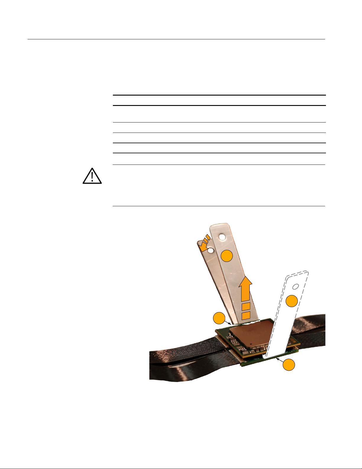
Extractor Tool
Use these steps and the extractor tool to remove the
microprocessor from the DUT and probe-head
socket:
Caution: To avoid damaging the probe head
cable connections, only pry on the sides of
the microprocessor that do not face the
cables.
1/4”
2
1. Position the extractor tool between the probe
head and the microprocessor.
2. Press down gently on the extractor tool to
pry up this side of the microprocessor.
3. Repeat steps 1 and 2 on the opposite side of
the microprocessor as shown.
4. Repeat steps 1 to 3 until the microprocessor
lifts out easily.
2
1
TMSSPH1 PGA604 Socket F
3
1
i Support Instructions
Page 9

NOTE. Retain the black case (for the probe head),
cardboard cartons, and packing material shipped with
the product.
Installation Instructions
Basic Configuration
Use the f ollowing steps to install the microprocessor
in the probe head:
1. Power off the DUT. It is not necessary to
power off the logic analyzer.
2. Power off any probe heads (or preprocessor
unit) that may be attached to the DUT.
3. Discharge any static electricity, by touching
the ground connector located on the logic
analyzer.
4. Remove the heat sink.
5. Open the ZIF lever.
6. Remove the microprocessor from the DUT
using the extractor tool. See the Extractor
Tool procedure on page 2.
4
6
5
TMSSPH1 PGA604 Socket Fi Support Instructions
3
Page 10

Installation Instructions
Check that the pin protector is in place on the
bottom of the probe head before inserting the
microprocessor into the probe head and that you are
wearing a grounding wrist strap.
7. Lubricate the microprocessor pins, and then
insert the microprocessor into the top of the
probe-head socket, aligning pin 1 identifiers
(
B).
From a standing position and using the heels
of both hands, apply a downward force to
the microprocessor. You will feel the
microprocessor slide into place.
Tektronix recommends that you use Miller Stephenson part number MS--381HM as the contact lubricant
when inserting the microprocessor into the probe
head. For more information about this lubricant, go
to the following Web site: http://www.miller-stephenson.com.
7
8. Check if the ZIF lever is oriented on the DUT
asshowninstep13onpage5withthe
heat sink mounting holes on the same side
as the ZIF lever. If it is, proceed with step 9
on page 5.
If the ZIF lever is oriented 90 degrees from the
heat sink mounting holes as shown on step 5 on
page 7, then go to page 7 to continue the
probe head installation using the 90 Degree
Rotated Configuration procedure.
4
TMSSPH1 PGA604 Socket F
i Support Instructions
Page 11
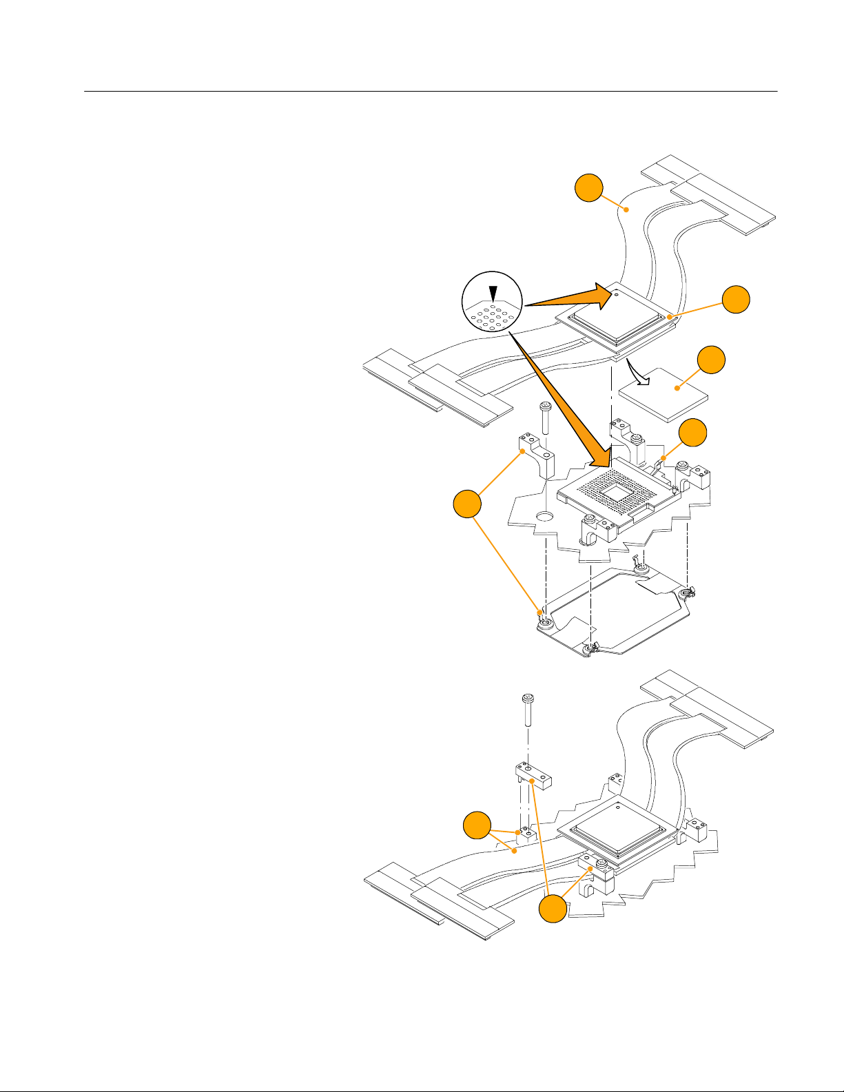
Follow these steps to attach the heat-sink brackets
and the probe head to the DUT:
9. Attach the four bottom heat-sink brackets
and screws to the DUT.
10. Remove the pin protector.
11. Fold cables up and away when attaching.
Installation Instructions
11
12. Attach the probe head to the DUT, aligning
pin 1 identifiers (
13. Close the ZIF lever on the ZIF socket.
14. Dress the cables over the bottom heat-sink
brackets.
B).
12
10
13
9
15. Attach the f our top heat-sink brackets and
screws.
TMSSPH1 PGA604 Socket Fi Support Instructions
14
15
5
Page 12

Installation Instructions
Follow these steps to attach the heat sink to the
DUT:
16. Apply thermal grease to the top of the copper spacer and the microprocessor.
17. Install the heat sink and copper spacer.
18. Attach the probe-head cables to the prepro-
cessor-unit cables (snap into place) paying
close attention that the labels on the paddle
boards match, such as A to A.
19. Apply forced-air cooling across the microprocessor and heat sink to keep the microprocessor from overheating unless you are using a forced-air cooled heat sink and fan assembly.
17
16
18
B
B
A
A
6
TMSSPH1 PGA604 Socket F
i Support Instructions
Page 13

90 Degree Rotated Configuration
To attach the heat -si nk spacer posts, the microprocessor, and the probe head to the DUT, follow these
steps:
Installation Instructions
1. Complete steps 1 -- 8. (See page 4.)
2. Attach four heat-sink spacer posts to t he
DUT.
3. Remove the pin protector.
4. Attach the probe head to the DUT, carefully
aligning pin 1 identifiers (
5. Close the ZIF lever on the ZIF socket .
Y).
2
4
3
5
4
2
TMSSPH1 PGA604 Socket Fi Support Instructions
7
Page 14

Installation Instructions
To attach the heat sink to t he DUT, follow these
steps:
6. Apply thermal grease to the top of the microprocessor.
7. Install the heat sink.
8. Attach the probe-head cables to the prepro-
cessor-unit cables (snap into place), paying
close attention that the labels on the paddle
boards match, such as A to A.
9. Apply forced-air cooling across the microprocessor and heat sink to keep the microprocessor from overheating unless you are using a forced-air cooled heat sink and fan assembly.
7
6
8
B
B
A
A
8
TMSSPH1 PGA604 Socket F
i Support Instructions
Page 15
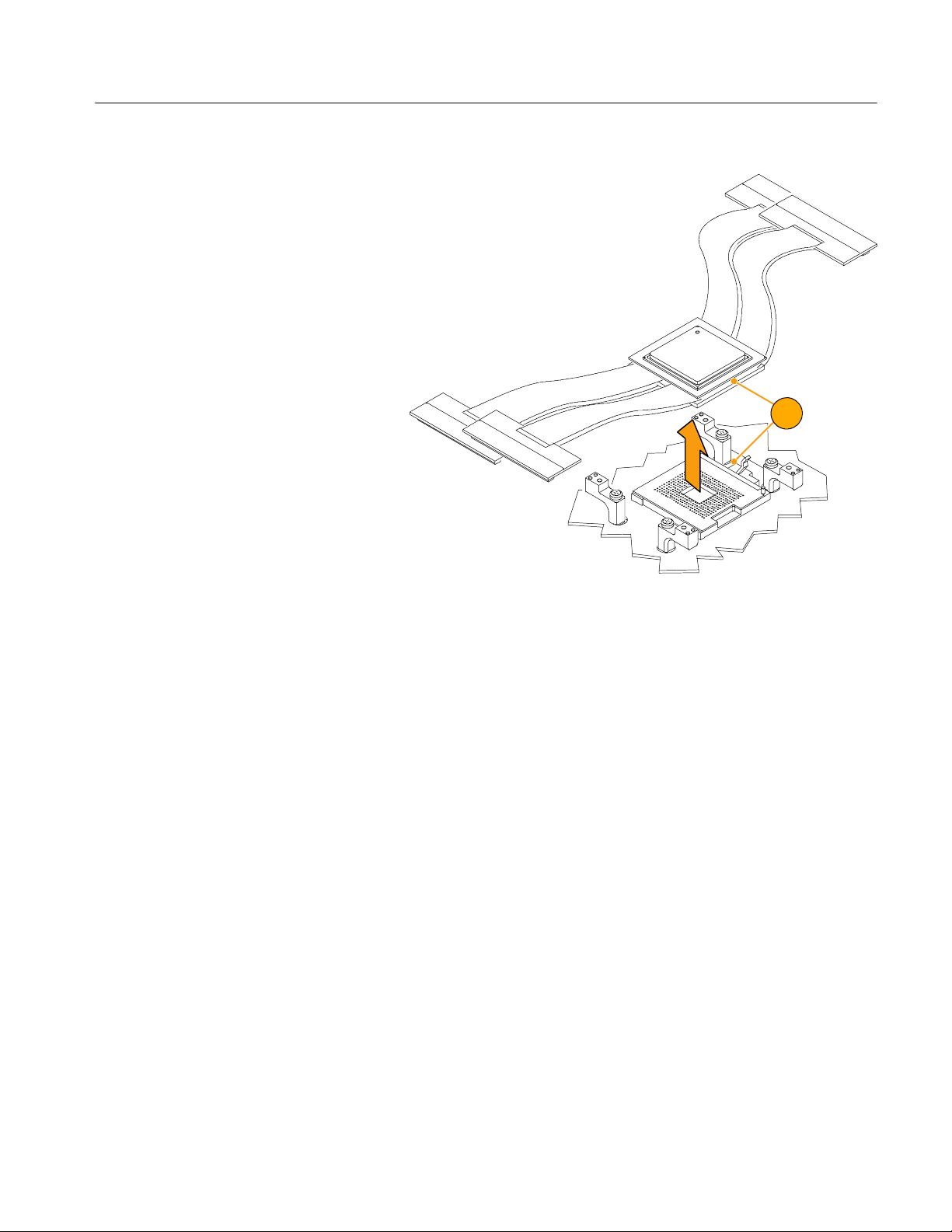
Probe Head Removal
Follow these steps to remove the probe head from
the DUT:
CAUTION. To prevent damage to the Socket Fi pins
on the probe head, use the provided extractor tool as
shown on page 2.
1. Power off the DUT and preprocessor unit. It
is not necessary to power off the logic analyzer.
2. If the ZIF lever is oriented on the DUT as
shown with the heat sink mounting holes on
the same side of the ZIF lever, reverse the
steps in the Basic Configuration procedure to
remove the probe head. (See Basic Configuration on page 2.)
If the ZIF lever is rotated 90 degrees from the
heat sink mounting holes, reverse the steps in
the 90 Degree Rotated Configuration procedure
to remove the probe head. (See 90 Degree
Rotated Configuration procedure on page 7.)
Installation Instructions
2
3. Store the probe head. (see page 13.)
Applying and Removing Power
To apply or remove power, refer to the instruction manual that came with the
compatible preprocessor unit.
TMSSPH1 PGA604 Socket Fi Support Instructions
9
Page 16

Installation Instructions
Installing the Software
NOTE. Before you install any software, verify that the microprocessor support
software is compatible with the logic analyzer software by comparing the version
number on the CD to the Tektronix logic analyzer system software.
To install the software on the Tektronix logic analyzer, follow these steps:
1. Insert the CD in the CD drive.
2. Select the Windows Start button > Control Panel > Add/Remove Programs.
3. Select the Add New Programs button on the left side of the display.
4. Select the CD or Floppy button.
5. Follow the on-screen instructions to install the software.
To remove or uninstall software, use the Add or Remove Programs utility in the
Windows Control Panel. Close all windows before you uninstall any software.
10
TMSSPH1 PGA604 Socket F
i Support Instructions
Page 17

Installation Instructions
Support Package Setup
After installing the software, you need to load the setup file. Follow these steps:
1. From the file menu, open a logic analyzer system window and select Load
Support Package.
2. In the Load Support Package dialog box, select the support and click load.
3. Follow the on-screen instructions.
2
1
Replaceable Parts List
Table 2: Replaceable Parts List
Step&page
number
12 -- 5 1 PROBE HEAD BOARD W/CABLES &
9--5 4 COVER; BOTTOM,HEAT SINK
9--5 4 SCREW,MACHINE; 6--32 X 0.75,
15 -- 5 4 COVER,TOP; HEAT SINK ATTACH; 200-4862-XX
15 -- 5 4 SCREW,MACHINE; 6--32 X
2--7 4 SPACER,POST 129-1638-XX
16 -- 6 1 SPACER;HEAT SINK ATTACH 361-1807-XX
5--14 1 CASE, STORAGE: PLASTIC, W/
Quantity Description Part number
TMSSPH1
PADDLE BOARD;TESTED
200-4861-XX
ATTACH;
211-0687-XX
FLH,100 DEG,STL CD PL,POZ
211-0511-XX
0.5,PNH,STL CD PL, POZ
016-1941-XX
FOAM, 12.4X8.9X2.9;FLEX CABLE
ASSEMBLY
TMSSPH1 PGA604 Socket Fi Support Instructions
11
Page 18
Installation Instructions
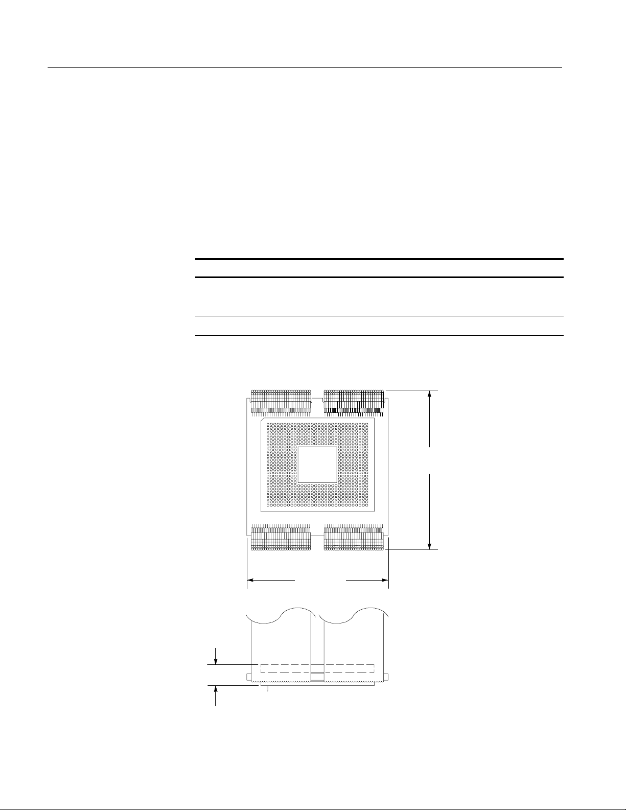
Specifications
The environmental specifications below are for a probe head connected between
a compatible Tektronix logic analyzer and a DUT. See Figure 1 for the probehead dimensions. For other specifications, refer to the TMSST2 LGA771, 775,
and PGA604 Hardware Support Manual (071-1665-XX).
Table 3: Environmental specifications
Characteristic Description
Temperature Maximum operating: 0 °Cto+55°C(+32°F to +131 °F)
Nonoperating: --20 °Cto+70°C(--4°F to +158 °F)
1
Electrostatic immunity
1
Not to exceed microprocessor thermal considerations. You may need to supply
cooling across the CPU.
53.721 mm
(2.115 in)
The probe adapter is static sensitive
59.66 mm
(2.349 in)
12
8.02 mm
(0.316 in)
Figure 1: Dimensions of the probe head
TMSSPH1 PGA604 Socket F
i Support Instructions
Page 19

Maintenance
Installation Instructions
Before cleaning this product, read the following information.
CAUTION. T o prevent static damage to the microprocessor and the probe head,
handle components only in a static-free environment. Always wear a grounding
wrist strap, heel strap, or similar device while handling the microprocessor and
probe head.
The probe head does not require scheduled or periodic maintenance. However, to
keep good electrical contact and efficient heat dissipation, keep the probe head
free of dirt, dust, and contaminants. When not in use, store the probe head in the
original case and cardboard carton.
External Cleaning Only
Storage
Clean dirt and dust with a soft bristle brush. For more extensive cleaning, use
only a damp cloth moistened with deionized water; do not use any other
chemical cleaning agents.
WARNING. To prevent personal injury or damage to the probe head, do not allow
any moisture inside the probe head. Refer servicing of external parts of the probe
head to only Tektronix authorized personnel. External parts may be replaced by
qualified service personnel.
CAUTION. T o prevent damage to the sensitive probe-head cables, handle them
with care.
T o prevent damage to the pins on the probe-head socket and microprocessor, use
the provided extractor tool. Refer to page 2.
For short-term storage, use the existing black case, and cushioning foam, and
read the cautions on this page. Follow these steps:
NOTE.
See page 2.
1. Power off the DUT and the preprocessor unit It is not necessary to power off
TMSSPH1 PGA604 Socket Fi Support Instructions
Use the extractor tool when you remove the microprocessor from the probe head.
the logic analyzer.
13
Page 20

Installation Instructions
2. To remove the heat sink, hardware, and probe head use the Probe Head
Removal procedure. See page 9.
3. Dress the probe-head cables so they do not pinch or contact any sharp
objects. When you fold the cables, use a minimum radius of 0.25 in (0.64
cm) at the fold.
4. Using non-static generating tape, tape the pin-protector board onto the pin
header on the bottom of the probe head.
5. Store the probe head in the black case it was shipped in.
5
Long-Term Storage
For long-term storage, use the existing black case, and if you have these; the
accessory tray and packaging:
1. Complete steps 1 through 5 in the Short-Term Storage procedure.
2. Place the black case in the accessory tray and carton, if you have these.
3. Close and tape the cardboard carton.
To ship the probe head, refer below to Shipping the Instrument to the Service
Center.
2
14
TMSSPH1 PGA604 Socket F
i Support Instructions
Page 21

Shipping the Instrument to the Service Center
Contact the Service Center to obtain an RMA (return material authorization)
number.
To commercially transport the probe head, package as follows:
1. Use the existing probe-head case and a cardboard shipping carton. Follow
the steps on page 13 to package the probe head.
If the existing shipping carton is not available, use a double-walled,
corrugated cardboard shipping carton that allows a 3 inch (7.62 cm)
minimum on all sides of the product.
2. If you are shipping a probe head to a Tektronix service center for warranty
service, attach a tag to the probe head showing the following:
H The RMA number
H Owner’s name and address
Installation Instructions
Accessories
Table 4:
Quantity Accessory Part number
1 SOFTWARE PKG; W/INSTRUCTIONS MANUAL, TMSSPH1
1 TOOL, EXTRACTION;PGA SOCKET,TWO-SIDED,19 TEETH PER
Standard Accessories
H Name of a person who can be contacted
H Probe-head type and serial number
H Description of the problem
Mark the address of the Tektronix Service Center and the return address on
the shipping carton in two prominent locations.
The following standard accessories are shipped with the probe head.
063-3982-XX
PUB32G16
003-1884-XX
SIDE;1710--19
No optional accessories are available for the probe head.
TMSSPH1 PGA604 Socket Fi Support Instructions
15
Page 22

Installation Instructions
16
TMSSPH1 PGA604 Socket F
i Support Instructions
 Loading...