

Page 1

Service Manual
TLA600 Series
Logic Analyzer
071-0728-01
Warning
The servicing instructions are for use by qualified
personnel only. To avoid personal injury, do not
perform any servicing unless you are qualified to
do so. Refer to all safety summaries prior to
performing service.
www.tektronix.com
Page 2

Copyright © Tektronix, Inc. All rights reserved.
Tektronix products are covered by U.S. and foreign patents, issued and pending. Information in this publication supercedes
that in all previously published material. Spec ifications and price change privileges reserved.
Tektronix, Inc., P.O. Box 500, Beaverton, OR 97077
TEKTRONIX and TEK are registered trademarks of Tektronix, Inc.
Page 3

HARDWARE WARRANTY
Tektronix warrants that the products that it manufactures and sells will be free from defects in materials and workmanship
for a period of one (1) year from the date of shipment. If a product prove s defective during this warranty period, Tektronix,
at its option, either will repair the defective product without charge for parts and labor, or will provide a replacement in
exchange for the defective product.
In order to obtain service under this warranty, Customer must notify Tektronix of the de fect before the expiration of the
warranty period and make suitable arrangements for the performance of service. Customer shall be responsible for
packaging and shipping the defective product to the service center designated by Tektronix, with shipping charges prepaid.
Tektronix shall pay for the return of the product to Customer if the shipment is to a location within the country in which the
Tektronix service center is located. Customer shall be responsible for paying all shipping charges, duties, taxes, and any
other charges for products returned to any other locations.
This warranty shall not apply to any defect, failure or damage caused by improper use or improper or inadequate
maintenance and care. Tektronix shall not be obligated to furnish service under this warranty a) to repair damage resulting
from attempts by personnel other than Tektronix representatives to install, repair or service the product; b) to repair
damage resulting from improper use or connection to incompatible equipment; c) to repair any damage or malfunction
caused by the use of non-Tektronix supplies; or d) to service a product that has been modifie d or integrated with other
products when the effect of such modification or integration increases the time or difficulty of servicing the product.
THIS W ARRANTY IS GIVEN BY TEKTRONIX IN LIEU OF ANY OTHER WARRANTIES, EXPRESS OR
IMPLIED. TEKTRONIX AND ITS VENDORS DISCLAIM ANY IMPLIED WARRANTIES OF
MERCHANTABILITY OR FITNESS FOR A PARTICULAR PURPOSE. TEKTRONIX’ RESPONSIBILITY TO
REPAIR OR REPLACE DEFECTIVE PRODUCTS IS THE SOLE AND EXCLUSIVE REMEDY PROVIDED TO
THE CUSTOMER FOR BREACH OF THIS W ARRANTY. TEKTRONIX AND ITS VENDORS WILL NOT BE
LIABLE FOR ANY INDIRECT, SPECIAL, INCIDENT AL, OR CONSEQUENTIAL DAMAGES IRRESPECTIVE
OF WHETHER TEKTRONIX OR THE VENDOR HAS ADVANCE NOTICE OF THE POSSIBILITY OF SUCH
DAMAGES.
Page 4

Page 5

Table of Contents
Specifications
Operating Instructions
General Safety Summary ix...................................
Service Safety Summary xi....................................
Preface xiii...................................................
Manual Structure xiii................................................
Manual Conventions xiii..............................................
Contacting Tektronix xiv.............................................
Introduction xv..............................................
The TLA600 Series Logic Analyzer xvi.................................
Adjustment and Certification Interval xvii................................
Strategy for Servicing xvii.............................................
Service Offerings xviii................................................
Characteristic Tables 1--1.......................................
TLA600 Series Logic Analyzer Description 2--1...........................
User Interface 2--2...................................................
Operating System and Application Interface 2--6...........................
Online Help 2--6.....................................................
Software Installation and Removal 2--6..................................
Theory of Operation
Hardware 3--1.......................................................
Probe Interface 3--2..................................................
Acquisition 3--3.....................................................
Performance Verification
Performance V erification: Logic Analyzer 4--1.....................
Summary Verification 4--1.............................................
Test Equipment 4--3..................................................
Functional Verification 4--4............................................
Certification 4--9....................................................
Performance Verification Instructions 4--9................................
Performance Verification Tests 4--15.....................................
Performance V erification: Adjustment/Verification Fixture 4--21.......
Test Equipment 4--21..................................................
Functional Verification 4--21............................................
Certification 4--25....................................................
Performance Verification 4--25..........................................
Test Procedures 4--27..................................................
Calibration Data Report 4--37...................................
TLA600 Series Logic Analyzer Service Manual
i
Page 6

Table of Contents
Adjustment Procedures
Maintenance
TLA600 Adjustment Procedures 5--1.............................
Prerequisites 5--1....................................................
Using the Software 5--2...............................................
Test Equipment 5--2..................................................
Adjustment Instructions 5--3...........................................
Tests Performed 5--4.................................................
Adjustment Procedures 5--5............................................
Self Calibration 5 --5..................................................
Completing the Adjustment Steps 5--7...................................
Adjustment/Verification Fixture Adjustments 5--9..................
Adjustment/Verification Fixture Adjustment 5--9...........................
Preparation 6 --1.....................................................
Preventing ESD 6--1.................................................
Inspection and Cleaning 6--2...........................................
Removal and Installation Procedures 6--5.........................
Preparation 6 --5.....................................................
General Instructions 6--5..............................................
Equipment Required 6--6..............................................
Removing the Trim and Covers 6--7.....................................
Adding Memory 6--12.................................................
Removing the Display 6--13............................................
Display Adapter Board 6--14............................................
Standby/On Switch Flex Circuit Removal 6--15.............................
Removing the Closed Face Bracket (TLA 60X Series) 6--17...................
Front-Panel Knobs 6--18...............................................
Front Panel Assembly 6--19.............................................
Front Panel Board 6--21................................................
Front Panel Keypad 6--22..............................................
Replacing the Hard Disk Drive 6--24.....................................
Replacing the Floppy Disk Drive 6--26....................................
Replacing the CD ROM Drive 6--28......................................
Replacing the CPU Board 6--30.........................................
Replacing the Microprocessor 6--32......................................
Replacing the Interface Board 6--34......................................
Replacing the Acquisition Board 6--36....................................
Replacing the Power Supply 6--38.......................................
Replacing the Fan Assembly 6--39.......................................
Verifying Operation 6--40..............................................
Troubleshooting 6--41...........................................
Service Level 6 --41...................................................
Check for Common Problems 6--42.....................................
Diagnostics 6--43.....................................................
Repackaging Instructions 6--47...................................
Packaging 6--47......................................................
Shipping to the Service Center 6--47......................................
ii
TLA600 Series Logic Analyzer Service Manual
Page 7

Options
Electrical Parts List
Diagrams
Mechanical Parts List
Table of Contents
Probe Options 7--1...................................................
Hardware Architechure Block Diagram 9--1............................
Interconnection Block Diagram 9--2.....................................
System Block Diagram 9--3............................................
Parts Ordering Information 10-- 1.........................................
Using the Replaceable Parts List 10--2....................................
TLA600 Series Logic Analyzer Service Manual
iii
Page 8

Table of Contents
List of Figures
Figure i: TLA600 Series logic analyzers xvi.......................
Figure 1--1: Dimensions of the TLA600 series logic analyzer 1--13......
Figure 2--1: TLA600 series logic analyzers 2--1.....................
Figure 4--1: Calibration/certification procedure flow chart 4--2.......
Figure 4--2: Probe functional verification test setup 4--7..............
Figure 4--3: Activity monitor 4--8.................................
Figure 4--4: Adjustment/verification fixture connections and
jumper locations 4--16.......................................
Figure 4--5: FPV_DC_Threshold test setup 4--17.....................
Figure 4--6: Initial FPV_Setup_0F test setup 4--18...................
Figure 4--7: Initial FPV_Hold_0F test setup 4--19....................
Figure 4--8: FPV_Maxsync test setup 4--20..........................
Figure 4--9: Adjustment/verification fixture detail 4--23...............
Figure 4--10: Probe tip adapter detail 4--26........................
Figure 4--11: Adjustment/verification fixture detail 4--28..............
Figure 5--1: P6434 probe detail 5--3...............................
Figure 5--2: Initial deskew test setup 5--6..........................
Figure 5--3: Adjustment/verification fixture circuit board layout 5--11...
Figure 6--1: Trim and covers 6--9................................
Figure 6--2: Closed face trim ring and covers (TLA 60X Series) 6--10...
Figure 6--3: Internal covers 6--11..................................
Figure 6--4: Memory board location 6--12..........................
Figure 6--5: Flat panel display assembly removal 6--14..............
Figure 6--6: Display adaptor board removal 6--15....................
Figure 6--7: Standby/On switch flex circuit removal 6--16.............
Figure 6--8: Removal of the closed face bracket 6--17.................
Figure 6--9: Knob removal 6--18..................................
Figure 6--10: Front panel assembly removal 6--20....................
Figure 6--11: JR1 flex cable connector removal 6--21.................
Figure 6--12: Front panel board & keyboard removal 6--22............
Figure 6--13: Hard disk drive replacement 6--25.....................
iv
TLA600 Series Logic Analyzer Service Manual
Page 9

Table of Contents
Figure 6--14: Floppy disk drive location 6--27.......................
Figure 6--15: CD-ROM drive location 6--29........................
Figure 6--16: Replacing the CPU board 6--31........................
Figure 6--17: Microprocessor removal 6--33.........................
Figure 6--18: Replacing the interface board 6--35....................
Figure 6--19: Replacing the acquisition board 6--37..................
Figure 6--20: Power supply mounting screw location 6--38.............
Figure 6--21: Replacing the fan assembly 6--40......................
Figure 9--1: Logic analyzer hardware architecture 9--1..............
Figure 9--2: Logic analyzer interconnection block diagram 9--2.......
Figure 9--3: Logic analyzer system block diagram 9--3...............
Figure 10--1: External parts 10--7................................
Figure 10--2: Front panel, display, hard drive, and floppy drive 10--9...
Figure 10--3: Power supply, processor, and CD drive 10--13............
Figure 10--4: Acquisition assembly 10--15............................
Figure 10--5: Accessories 10--16....................................
Figure 10--6: Adjustment/verification fixture exploded view 10--19.......
TLA600 Series Logic Analyzer Service Manual
v
Page 10

Table of Contents
List of Tables
Table i: TLA600 series family xvi...............................
Table 1--1: TLA600 input parameters with probes 1--1..............
T able 1--2: TLA600 timing latencies 1--2.........................
Table 1--3: TLA600 external signal interface 1--3..................
Table 1--4: TLA600 channel width and depth 1--5..................
Table 1--5: TLA600 clocking 1--5................................
Table 1--6: TLA600 trigger system 1--7...........................
Table 1--7: TLA600 MagniVu feature 1--10.........................
Table 1--8: TLA600 Data handling 1--10...........................
Table 1--9: TLA600 internal controller 1--10........................
Table 1--10: TLA600 display system 1--11..........................
Table 1--11: TLA600 front-panel interface 1--11.....................
Table 1--12: TLA600 rear-panel interface 1--11......................
Table 1--13: TLA600 AC power source 1--12........................
Table 1--14: TLA600 cooling 1--12................................
Table 1--15: TLA600 mechanical characteristics 1--13................
T able 1--16: Atmospheric characteristics 1--14......................
Table 1--17: Certifications and compliances 1--14....................
T able 1--18: Adjustment/verification fixture specifications 1--16........
Table 2--1: USB (universal serial bus) pin assignments 2--2..........
Table 2--2: SVGA OUT pin assignments 2--4......................
Table 2--3: COM OUT pin assignments 2--4.......................
Table 2--4: LPT (parallel interface) pin assignments 2--5............
Table 4--1: Test equipment 4--3..................................
Table 4--2: TLA600 Functional verification procedures 4--4..........
Table 4--3: TLA600 PV/Adjust software performance verification
tests 4--10.................................................
T able 4--4: TLA600 characteristics indirectly checked by the
performance verification and adjustment software performance
verification tests 4--11.......................................
T able 4--5: Adjustment/verification fixture performance verification
tests 4--25.................................................
T able 4--6: Adjustment/verification fixture jumper settings 4--28.......
vi
TLA600 Series Logic Analyzer Service Manual
Page 11

Table of Contents
Table 6--1: Tools required for module removal 6--6.................
Table 6--2: Failure symptoms and possible causes 6--42...............
Table 6--3: TLA 700 Power-on diagnostic tests 6--44.................
Table 6--4: BIOS error codes and explanations 6--45.................
Table 7--1: Probe options 7--1...................................
Table 10--1: Parts lists column descriptions 10--2....................
TLA600 Series Logic Analyzer Service Manual
vii
Page 12

Table of Contents
viii
TLA600 Series Logic Analyzer Service Manual
Page 13

General Safety Summary
Review the following safety precautions to avoid injury and prevent damage to
this product or any products connected to it. To avoid potential hazards, use this
product only as specified.
Only qualified personnel should perform service procedures.
While using this product, you may need to access other parts of the system. Read
the General Safety Summary in other system manuals for warnings and cautions
related to operating the system.
ToAvoidFireor
Personal Injury
Use Proper Power Cord. Use only the power cord specified for this product and
certified for the country of use.
Use Proper Voltage Setting. Before applying power, ensure that the line selector is
in the proper position for the power source being used.
Connect and Disconnect Properly. Do not connect or disconnect probes or test
leads while they are connected to a voltage source.
Ground the Product. This product is grounded through the grounding conductor
of the power cord. To avoid electric shock, the grounding conductor must be
connected to earth ground. Before making connections to the input or output
terminals of the product, ensure that the product is properly grounded.
Observe All Terminal Ratings. To avoid fire or shock hazard, observe all ratings
and markings on the product. Consult the product manual for further ratings
information before making connections to the product.
Do not apply a potential to any terminal, including the common terminal, that
exceeds the maximum rating of that terminal.
Do Not Operate Without Covers. Do not operate this product with covers or panels
removed.
Use Proper Fuse. Use only the fuse type and rating specified for this product.
Avoid Exposed Circuitry. Do not touch exposed connections and components
when power is present.
Do Not Operate With Suspected Failures. If you suspect there is damage to this
product, have it inspected by qualified service personnel.
Do Not Operate in Wet/Damp Conditions.
Do Not Operate in an Explosive Atmosphere.
Keep Product Surfaces Clean and Dry.
TLA600 Series Logic Analyzer Service Manual
ix
Page 14
General Safety Summary
Provide Proper Ventilation. Refer to the manual’s installation instructions for
details on installing the product so it has proper ventilation.
Symbols and Terms
Terms in this Manual. These terms may appear in this manual:
WARNING. Warning statements identify conditions or practices that could result
in injury or loss of life.
CAUTION. Caution statements identify conditions or practices that could result in
damage to this product or other property.
Terms on the Product. These terms may appear on the product:
DANGER indicates an injury hazard immediately accessible as you read the
marking.
WARNING indicates an injury hazard not immediately accessible as you read the
marking.
CAUTION indicates a hazard to property including the product.
Symbols on the Product. The following symbols may appear on the product:
Battery Recycling
CAUTION
Refer to Manual
WARNING
High Voltage
Protective Ground
(Earth) Terminal
This product contains a Nickel Cadmium (NiCd) battery, which must be recycled
or disposed of properly. For the location of a local battery recycler in the U.S. or
Canada, please contact:
RBRC (800) BATTERY
Rechargeable Battery Recycling Corp. (800) 227-7379
P.O. Box 141870 www.rbrc.com
Gainesville, Florida 32614
x
TLA600 Series Logic Analyzer Service Manual
Page 15

Service Safety Summary
Only qualified personnel should perform service procedures. Read this Service
Safety Summary and the General Safety Summary before performing any service
procedures.
Do Not Service Alone. Do not perform internal service or adjustments of this
product unless another person capable of rendering first aid and resuscitation is
present.
Disconnect Power. To avoid electric shock, switch off the instrument power, then
disconnect the power cord from the mains power.
Use Care When Servicing With Power On. Dangerous voltages or currents may
exist in this product. Disconnect power, remove battery (if applicable), and
disconnect test leads before removing protective panels, soldering, or replacing
components.
To avoid electric shock, do not touch exposed connections.
TLA600 Series Logic Analyzer Service Manual
xi
Page 16

Service Safety Summary
xii
TLA600 Series Logic Analyzer Service Manual
Page 17

Preface
Manual Structure
Manual Conventions
This is the service manual for the TLA600 Series Logic Analyzer Read this
preface to learn how this manual is structured, what conventions it uses, and
where you can find other information related to servicing this product. Read the
Introduction following this preface for safety and other important background
information needed before using this manual for servicing this product.
This manual is divided into chapters, which are made up of related subordinate
topics. These topics can be cross referenced as sections.
Be sure to read the introductions to all procedures. These introductions provide
important information needed to do the service correctly, safely, and efficiently.
This manual uses certain conventions that you should become familiar with
before attempting service.
Safety
Specifications
Replaceable Parts
Symbols and terms related to safety appear in the Service Safety Summary found
at the beginning of this manual.
All specifications and characteristics are located in the user manual. You will
need a copy of the user manual in order to perform many of the tasks in this
manual.
This manual refers to any field-replaceable assembly or mechanical part
specifically by its name or generically as a replaceable part. In general, a
replaceable part is any circuit board or assembly that is listed in the replaceable
parts list.
TLA600 Series Logic Analyzer Service Manual
xiii
Page 18

Preface
Contacting Tektronix
Phone 1-800-833-9200*
Address Tektronix, Inc.
Department or name (if known)
14200 SW Karl Braun Drive
P.O. Box 500
Beaverton, OR 97077
USA
Web site www.tektronix.com
Sales support 1-800-833-9200, select option 1*
Service support 1-800-833-9200, select option 2*
Technical support Email: techsupport@tektronix.com
1-800-833-9200, select option 3*
1-503-627-2400
6:00 a.m. -- 5:00 p.m. Pacific time
* This phone number is toll free in North America. After office hours, please leave a
voice mail message.
Outside North America, contact a Tektronix sales office or distributor; see the
Tektronix web site for a list of offices.
xiv
TLA600 Series Logic Analyzer Service Manual
Page 19

Introduction
This manual contains information needed to properly service the logic analyzer.
This introduction contains information critical to safe and effective servicing.
To prevent personal injury or damage to the logic analyzer, consider the
following requirements before attempting service:
H Read the General Safety Summary and Service Safety Summary found at the
beginning of this manual.
H The procedures in this manual should only be performed by a qualified
service person.
H Read the Preface.
H Read Operating Information chapter.
Be sure to follow all warnings, cautions and notes.
TLA600 Series Logic Analyzer Service Manual
xv
Page 20

Introduction
The TLA600 Series Logic Analyzer
The TLA600 Series logic analyzer is an instrument that is a high-performance
logic analyzer.
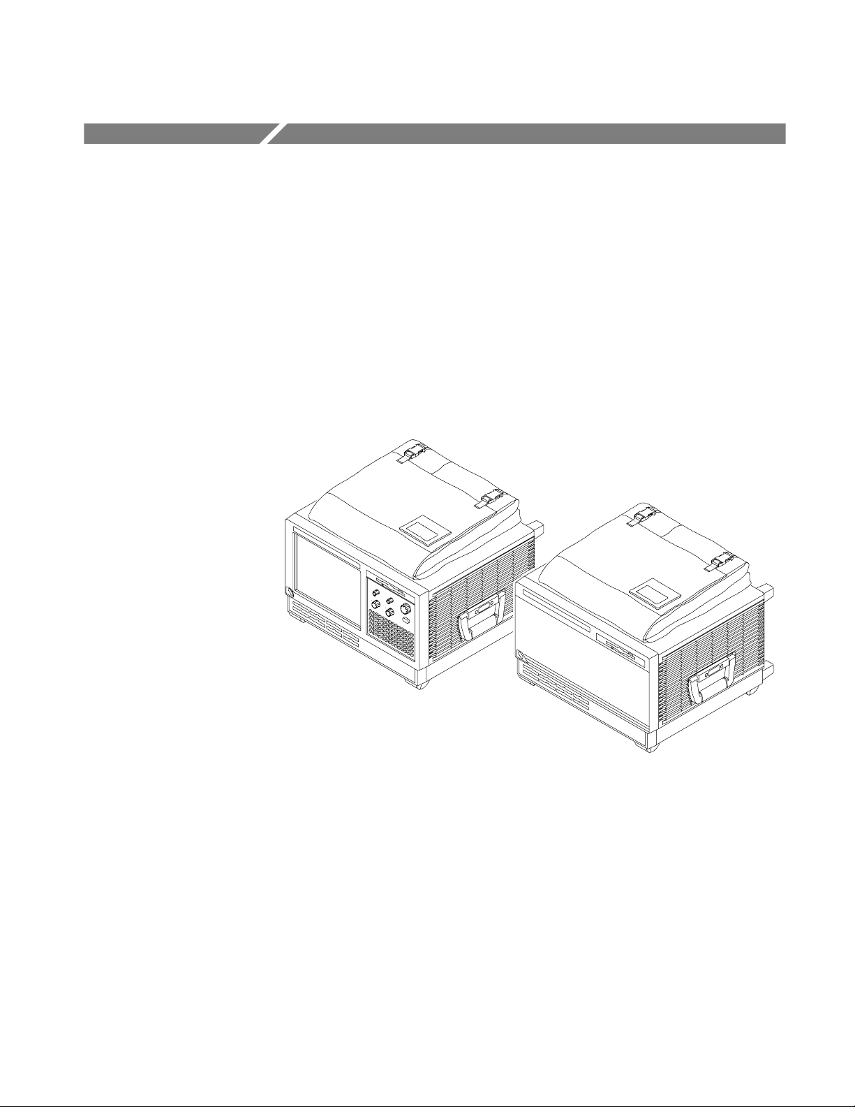
There are two basic styles, one style has an internal display, and the other style
uses an external display. Both styles are shown in figure Figure i.
xvi
Figure i: TLA600 Series logic analyzers
The TLA600 series is comprised of 12 logic analyzers as listed in Table i.
Table i: TLA600 series family
Logic analyzer Description
TLA601 34 channel, 2 GHz timing, 100 MHz state, 64 K depth
External display only
TLA602 68 channel, 2 GHz timing, 100 MHz state, 64 K depth
External display only
TLA603 102 channel, 2 GHz timing, 100 MHz state, 64 K depth
External display only
TLA604 136 channel, 2 GHz timing, 100 MHz state, 64 K depth
External display only
TLA600 Series Logic Analyzer Service Manual
Page 21

Table i: TLA600 series family (Cont.)
Logic analyzer Description
TLA611 34 channel, 2 GHz timing, 100 MHz state, 64 K depth
Internal and external display
TLA612 68 channel, 2 GHz timing, 100 MHz state, 64 K depth
Internal and external display
TLA613 102 channel, 2 GHz timing, 100 MHz state, 64 K depth
Internal and external display
TLA614 136 channel, 2 GHz timing, 100 MHz state, 64 K depth
Internal and external display
TLA621 34 channel, 2 GHz timing, 100 MHz state, 1 M depth
Internal and external display
TLA622 68 channel, 2 GHz timing, 100 MHz state, 1 M depth
Internal and external display
TLA623 102 channel, 2 GHz timing, 100 MHz state, 1 M depth
Internal and external display
TLA624 136 channel, 2 GHz timing, 100 MHz state, 1 M depth
Internal and external display
Introduction
Adjustment and Certification Interval
Generally, you should perform the adjustments and certification (calibration)
described in the Performance Verification and Adjustment Procedures chapters
once per year, or following repairs that affect adjustment or calibration.
Strategy for Servicing
This manual supports and contains information needed for periodic maintenance
of the logic analyzer.
This manual supports and contains information for corrective maintenance of this
product:
H supports isolation of faults to the failed circuit board or assembly level
shown in the replaceable parts list of Chapter 10
H supports removal and replacement of those boards or assemblies
H supports removal and replacement of the fuse, knobs, chassis, and other
mechanical parts listed in the replaceable parts list
This manual does not support component-level fault isolation and replacement.
TLA600 Series Logic Analyzer Service Manual
xvii
Page 22

Introduction
Service Offerings
Tektronix provides service to cover repair under warranty as well as other
services that are designed to meet your specific service needs.
Whether providing warranty repair service or any of the other services listed
below, Tektronix service technicians are equipped to service the logic analyzer.
Services are provided at Tektronix Services Centers and on-site at your facility,
depending on your location.
Warranty Repair Service
Calibration and Repair
Service
Tektronix warrants this product for one year from date of purchase. The warranty
is located behind the title page in this manual. Tektronix technicians provide
warranty service at most Tektronix service locations worldwide. The Tektronix
product catalog lists all service locations worldwide, or you can visit us on our
Customer Services W orld Center web site at:
Tektronix.com/Measurement/Service
In addition to warranty repair, Tektronix Service offers calibration and other
services which provide solutions to your service needs and quality standards
compliance requirements.
The following services can be tailored to fit your requirements for calibration
and/or repair of your logic analyzer.
Service Options. Tektronix Service Options can be selected at the time you
purchase your instrument. You select these options to provide the services that
best meet your service needs. These service options are listed on the Tektronix
Service Options page following the title page of this manual.
Service Agreements. If service options are not added to the instrument purchase,
then service agreements are available on an annual basis to provide calibration
services or post-warranty repair coverage. Service agreements may be customized to meet special turn-around time and/or on-site requirements.
xviii
Service on Demand. Tektronix offers calibration and repair services on a
“per-incident” basis that is available with standard prices.
Self Service. Tektronix supports repair to the replaceable-part level by providing
for circuit board exchange.
Use this service to reduce down-time for repair by exchanging circuit boards for
remanufactured ones. Tektronix ships updated and tested exchange boards. Each
board comes with a 90-day service warranty.
For More Information. Contact your local Tektronix service center or sales
engineer for more information on any of the Calibration and Repair Services just
described.
TLA600 Series Logic Analyzer Service Manual
Page 23

Specifications
Characteristic Tables
This chapter contains the specifications for the logic analyzer and for the
adjustment/verification fixture.
All specifications are guaranteed unless noted Typical. T ypical characteristics
describe typical or average performance and provide useful reference information.
Specifications that are check marked with the n symbol are checked directly (or
indirectly) in the Performance Verification chapter of this manual.
The specifications apply to all versions of the TLA600 series logic analyzer
unless otherwise noted.
The performance limits in this specification are valid with these conditions:
H The logic analyzer must be in an environment with temperature, altitude,
humidity, and vibration within the operating limits described in these
specifications.
H The logic analyzer must have had a warm-up period of at least 30 minutes.
Table 1- 1: TLA600 input parameters with probes
Characteristic Description
n Threshold Accuracy ±100 mV
Threshold range and step size Setable from +5 V to --2 V in 50 mV steps
Threshold channel selection 16 threshold groups assigned to channels.
P6417 and P6418 probes have two threshold settings, one for the clock/qualifier
channel and one for the data channels.
P6434 probes have four threshold settings, one for each of the clock/qualifier
channels and two for the data channels (one per 16 data channels).
n Channel-to-channel skew ≤ 1.6 ns maximum
Channel-to-channel skew
(Typical)
Sample uncertainty
Asynchronous: Sample period
Synchronous: 500 ps
Probe input resistance
(Typical)
≤ 1.0 ns
20 kΩ
TLA600 Series Logic Analyzer Service Manual
1- 1
Page 24
Specifications
Table 1- 1: TLA600 input parameters with probes (Cont.)
Characteristic Description
Probe input capacitance: P6417, P6434
2pF
(Typical)
Probe input capacitance: P6418
(Typical)
Minimum slew rate
1.4 pF data channels
2 pF CLK/Qual channels
0.2 V/ns
(Typical)
Maximum operating signal 6.5 V
--3.5 V absolute input voltage minimum
6.5 V absolute i nput vol tage maximum
Probe overdrive:
P6417, P6418
±250 mV or ±25% of signal swing minimum required beyond threshold, whichever is
greater
P6434
±300 mV or ±25% of signal swing minimum required beyond threshold, whichever is
greater
±4 V maximum beyond threshold
Maximum nondestructive input signal to probe ±15 V
Minimum input pulse width signal
2ns
(single channel)
(Typical)
Delay time from probe tip to input probe
7.33 ns
connector
(Typical)
p-p
Table 1- 2: TLA600 timing latencies
Characteristic Description
System Trigger and External Signal Input
1
Latencies
(Typical)
External System Trigger Input to LA Probe
2
Tip
External Signal Input to LA Probe Tip via
Signal 3, 4
3
External Signal Input to LA Probe Tip via
Signal 1, 2
3, 4
--266 ns
--212 ns + Clk
--208 ns + Clk
System Trigger and External Signal Output
Latencies (Typical)
LA Probe Tip to External System Trigger
5
Out
376 ns + SMPL
LA Probe Tip to External Signal Out via
Signal 3, 4
5
1- 2
TLA600 Series Logic Analyzer Service Manual
Page 25
Table 1- 2: TLA600 timing latencies (Cont.)
Characteristic Description
OR function 366 ns + SMPL
AND function 379 ns + SMPL
Specifications
LA Probe Tip to External Signal Out via
Signal 1, 2
4, 5
normal function 364 ns + SMPL
inverted logic on backplane 364 ns + SMPL
1
All system trigger and external signal input latencies are measured from a falling-edge transition (active true low) with
signals measured in the wired-OR configuration.
2
In the Waveform window, triggers are always marked immediately except when delayed to the first sample. In the Listing
window, triggers are always marked on the next sample period following their occurrence.
3
“Clk” represents the time to the next master clock at the destination logic analyzer. In the asynchronous (or internal)
clock mode, this represents the delta time to the next sample clock beyond the minimum asynchronous rate of 4 ns. In
the synchronous (or external) clock mode, this represents the tim e to the next master clock generated by the setup of the
clocking state machine and the supplied system under test clocks and qualification data.
4
Signals 1 and 2 (ECLTRG0, 1) are limited to a “broadcast” mode of operation, where only one source is allowed to drive
the signal node at any one time. That single source may be utilized to drive any combination of destinations.
5
SMPL represents the time from the event at the probe tip inputs to the next valid data sample. In the Normal Internal clock
mode, this represents the delta time to the next sample clock. In the MagniVu Internal clock mode, this represents 500 ps
or less. In the External clock mode, this represents the time to the next master clock generated by the setup of the
clocking state machine, the system-under-test supplied clocks, and the qualification data.
Table 1- 3: TLA600 external signal interface
Characteristic Description
System Trigger Input TTL compatible input via rear panel mounted BNC connectors
Input Levels
V
IH
V
IL
TTL compatible input.
≥ 2.0 V
≤ 0.8 V
Input Mode Falling edge sensitive, latched (active low)
Minimum Pulse Width 12 ns
Active Period Accepts system triggers during valid acquisition periods via real-time gating, resets system
trigger input latch between valid acquisition periods
Maximum Input Voltage 0 to +5 V peak
External Signal Input TTL compatible input via rear panel mounted BNC connectors
Input Destination Signal 1, 2, 3, 4
Input Levels
V
IH
V
IL
TTL compatible input.
≥ 2.0 V
≤ 0.8 V
TLA600 Series Logic Analyzer Service Manual
1- 3
Page 26

Specifications
Table 1- 3: TLA600 external signal interface (Cont.)
Characteristic Description
Input Mode Active (true) low, level sensitive
Input Bandwidth
Signal 1, 2
Signal 3, 4
Active Period Accepts signals during valid acquisition periods via real-time gating
Maximum Input Voltage 0 to +5 V peak
System Trigger Output TTL compatible output via rear panel mounted BNC connectors
Source Mode Active (true) low, falling edge latched
Active Period Outputs system trigger state during valid acquisition period, resets system trigger output to false
Output Levels
V
OH
1
50 MHz square wave minimum
10 MHz square wave minimum
state between valid acquisitions
50 Ω back terminated TTL-compatible output
≥4 V into open circuit
≥ 2Vinto50Ω to ground
V
OL
≤ 0.7Vsinking10ma
Output Protection Short-circuit prot ected (to ground)
External Signal Output TTL compatible outputs via rear panel mounted BNC connectors
Source Selection Signal 1, 2, 3, 4, or 10 MHz clock
Output Modes
Level Sensitive
Output Levels
V
OH
User definable
Active (true) low or active (true) high
50 Ohm back terminated TTL output
≥ 4 V into open circuit
≥ 2Vinto50Ω to ground
V
OL
Output Bandwidth
Signal 1, 2
Signal 3, 4
2
≤ 0.7Vsinking10ma
50 MHz square wave minimum
10 MHz square wave minimum
Active Period Outputs signals during valid acquisition periods, resets signals to false state between valid
acquisitions
Outputs 10 MHz clock conti nuously
Output Protection Short-circuit prot ected (to ground)
Intermodule Signal Line
Minimum bandwidth up to which the signals are specifi ed to operate correctly
Bandwidth
Signal 1, 2 (ECLTRG 0,1)
Signal 3, 4 (ECLTRG 0,1)
1
The Input Bandwidth specification only applies to signals to the modules; it does not apply to signals applied to the
50 MHz square wave minimum
10 MHz square wave minimum
External Signal Input and sent back to the External Signal Output.
2
The Output Bandwidth specification only applies to signals from the modules; it does not apply to signals applied to the
External Signal Input and sent back to the External Signal Output.
1- 4
TLA600 Series Logic Analyzer Service Manual
Page 27

Specifications
Table 1- 4: TLA600 channel width and depth
Characteristic Description
Number of channels Product Channels
TLA601, TLA611, TLA621 32 data and 2 clock/qualifier
TLA602, TLA612, TLA622 64 data and 4 clock/qualifier
b TLA603, TLA613, TLA623 96 data, 4 clock/qualifier, and 2 qualifier
TLA604, TLA614, TLA624 128 data, 4 clock/qualifier, and 4 qualifier
Acquisition memory depth Product Memory depth
1
1
1
PowerFlex options
TLA601, TLA602, TLA603, TLA604 64 K or 256 K samples
TLA611, TLA612, TLA613, TLA614 64 K or 256 K samples
TLA621, TLA622, TLA623, TLA624 1 M samples
Table 1- 5: TLA600 clocking
Characteristic Description
Asynchronous clocking
n Internal sampling period
n Minimum recognizable word
(across all channels)
Synchronous clocking
Number of clock channels
Number of qualifier channels
1
2
4 ns to 50 ms in a 1--2--5 sequence
Channel-to-channel skew + sample uncertainty
Example: for a P6417 or a P6418 Probe anda4nssample
period=1.6ns+4ns=5.6ns
3
Product Clock channels
TLA601, TLA611, TLA621 2
TLA602, TLA612, TLA622 4
TLA603, TLA613, TLA623 4
TLA604, TLA614, TLA624 4
5
Product Qualifier channels
TLA601, TLA611, TLA621 0
TLA602, TLA612, TLA622 0
TLA603, TLA613, TLA623 2
TLA604, TLA614, TLA624 4
TLA600 Series Logic Analyzer Service Manual
1- 5
Page 28
Specifications
Table 1- 5: TLA600 clocking (Cont.)
Characteristic Description
n Setup and hold window size
(data and qualifiers)
Maximum window size = Maximum channel-to-channel skew + (2 x sample
uncertainty) + 0.4 ns
Maximum setup time = User interface setup time + 0.8 ns
Maximum hold time = User interface hol d ti me + 0.2 ns
Examples: for P6417 or a P6418 probe and user interface
setup and hold of 2.0/0.0 typical:
Maximum window size = 1.6 ns + (2 x 500 ps) + 0.4ns = 3.0 ns
Maximum setup time = 2.0 ns + 0.8 ns = 2.8 ns
Maximum hold time = 0.0 ns + 0.2 ns = 0.2ns
Setup and hold window size
(data and qualifiers)
(Typical)
Channel-to-channel skew (typical) + (2 x sample uncertaint y)
Example: for P6417 or P6418 Probe = 1 ns + (2 x 500 ps) = 2 ns
Setup and hold window range The setup and hold window can be moved for each channel group from +8.5 ns (Ts) to
--7.0 ns (Ts) in 0.5 ns steps (setup time). Hold time follows the setup time by the setup
and hold window size.
n Maximum synchronous clock rate
4
200 MHz in full speed mode (5 ns minimum between active clock edges)
100 MHz (10 ns minimum between active clock edges)
Demux clocking
TLA603, TLA613, TLA623
TLA604, TLA614, TLA624
Channels multiplex as follows:
A3(7:0) to D3(7:0)
A2(7:0) to D2(7:0)
A1(7:0) to D1(7:0)
A0(7:0) to D0(7:0)
TLA601, TLA611, TLA621
TLA602, TLA612, TLA622
Channels multiplex as follows:
A3(7:0) to C3(7:0)
A2(7:0) to C2(7:0)
A1(7:0) to D1(7:0) TLA602, TLA612, TLA622
A0(7:0) to D0(7:0) TLA602, TLA612, TLA622
Time between DeMux clock edges
(Typical)
Time between DeMux store clock edges
(Typical)
Data Rate
4
(Typical)
4
5 ns minimum between Demux clock edges in full-speed mode
10 ns minimum between Demux clock edges in half-speed mode
4
10 ns minimum between Demux master clock edges in full-speed mode
20 ns minimum between Demux master clock edges in half-speed mode
400 MHz (200 MHz option required) half channel.
(Requires channels to be multipl exed.)
These multiplexed channels double the memory depth.
1- 6
TLA600 Series Logic Analyzer Service Manual
Page 29

Specifications
Table 1- 5: TLA600 clocking (Cont.)
Characteristic Description
Clocking state machine
Pipeline delays Each channel group can be programmed with a pipeline delay of 0 through 3 active
clock edges.
1
It is possible to use storage control and only store data when it has changed (transitional storage).
2
Applies to asynchronous clocking only. Setup and hold window specification applies to synchronous clocki ng only.
3
Any or all of the clock channels may be enabled. For an enabled clock channel, either the rising, falling, or both edges
can be selected as the active clock edges. The clock channels are stored.
4
Full and half speed modes are controlled by PowerFlex options and upgrade kits.
5
All qualifier channels are stored. For custom clocking there are an additional 4 qualifier channel s on C2 3:0 regardless of
channel width.
Table 1- 6: TLA600 trigger system
Characteristic Description
Triggering resources
Word/Range recognizers 16 word recognizers. The word recognizers can be combined to form full width, double
bounded, range recognizers. The following selections are available:
16 word recognizers 0 range recognizers
13 word recognizers 1 range recognizer
10 word recognizers 2 range recognizers
7 word recognizers 3 range recognizers
4 word recognizers 4 range recognizers
Range recognizer channel order From most-significant probe group to least-significant probe group: C3 C2 C1 C0 E3
E2 E1 E0 A3 A2 D3 D2 A1 A0 D1 D0 Q3 Q2 Q1 Q0 CK3 CK2 CK1 CK0
Missing channels for modules with fewer than 136 channels are omitted.
Glitch detector
Minimum detectable glitch pulse wi dth
1,2
Each channel group can be enabl ed to detect a glitch
2.0 ns (single channel with P6417, P6418, or a P6434 probe)
(Typical)
Setup and hold violation detector
1,3
Each channel group can be enabled to detect a setup and hold violation. The range is
from 8 ns before the clock edge to 8 ns after the clock edge. The range can be
selected in 0.5 ns increments.
The setup and hold violation of each window can be individually programmed.
Transition detector
1
Each channel group can be enabled or disabled to detect a transition between the
current valid dat a sampl e and the previous valid data sample.
This mode can be used to create transitional storage selections where all channels
are enabled.
TLA600 Series Logic Analyzer Service Manual
1- 7
Page 30

Specifications
Table 1- 6: TLA600 trigger system (Cont.)
Characteristic Description
Counter/Timers 2 counter/timers, 51 bits wide, can be clocked up to 250 MHz.
Maximum count is 2
Maximum time is 9.007
51
.
6
seconds or 104 days.
Counters and timers can be set, reset, or tested and have zero reset latency.
External Signal In
1
A backplane input signal
External Trigger In A backplane input signal that causes the main acquisition and the MagniVu
acquisition to trigger if they are not already triggered
Active trigger resources 16 maximum (excluding counter/timers)
Word recognizers are traded off one-by-one as External Signal In, glitch detection,
setup and hold detection, or transition detecti on resources are added.
Trigger States 16
n Trigger State sequence rate Same rate as valid data samples received, 250 MHz maximum
Trigger machine actions
Main acquisition trigger Triggers the main acquisition memory
Main trigger position Trigger position is programmable to any data sample (4 ns boundaries)
MagniVu acquisition trigger Triggering of MagniVu memory is controlled by the main acquisition trigger
MagniVu trigger position The MagniVu trigger position is programmable within 4 ns boundaries and separate
from the main acquisition memory trigger position.
Increment counter Either of the two counter/timers used as counters can be incremental.
Start/Stop timer Either of the t wo counter/t imers used as timers can be started or stopped.
Reset counter/timer Either of the t wo counter/t imers can be reset.
When a counter/timer is used as a timer and is reset, the timer continues from the
started or stopped state that it was in prior to the reset.
Signal out A signal sent to the backplane to be used by other instruments
Trigger out A trigger out signal sent to t he backplane to trigger other instruments
1- 8
TLA600 Series Logic Analyzer Service Manual
Page 31

Specifications
Table 1- 6: TLA600 trigger system (Cont.)
Characteristic Description
Storage Control
Global storage Storage is allowed only when a specific condition is met. This condition can use any
of the trigger machi ne resources except for the counter/timers. Storage commands
defined in the current trigger state will override the global storage control.
Global storage can be used to start the acquisition with storage initially turned on
(default) or turned off.
By event Storage can be turned on or off; only the current sample can be stored. The event
storage control overrides any global storage commands.
Block storage When enabled, 31 samples are stored before and after the valid sample.
Not allowed when glitch storage or setup and hold violation is enabled.
Glitch violation storage The acquisition memory can be enabled to store glitch violation information with each
data sample when asynchronous clocking is used. The probe data storage size is
reduced by one half (the other half holds the violation information). The f astest
asynchronous clocking rate is reduced to 10 ns.
Setup and hold violation storage The acquisition memory can be enabled to store setup and hold violation information
with each data sample when synchronous clocking is used. The probe data storage
size is reduced by one half (the other half holds the violation information). The
maximum clock rate is reduced by half.
1
Each use of External Signal In, glitch detector, setup and hold violation detector, or transition detector requires a trade-off
of one word recognizer resource.
2
Any glitch i s subject to pulse width variation of up to the channel-to-channel skew specification + 0. 5 ns.
3
Any setup value is subject to variation of up to 1.8 ns; any hold value is subject to variation of up to 1.2 ns.
TLA600 Series Logic Analyzer Service Manual
1- 9
Page 32
Specifications
Table 1- 7: TLA600 MagniVu feature
Characteristic Description
MagniVu memory depth 2016 samples per channel
MagniVu sampling period Data is asynchronously sampled and stored every 500 ps in a separate high resolution
memory. There are no clocking options.
Table 1- 8: TLA600 Data handling
Characteristic Description
Nonvolatile memory retention time
(Typical)
Battery is integral to the NVRAM. Battery life is > 10 years.
Table 1- 9: TLA600 internal controller
Characteristic Descri pti on
Operating System Microsoft Windows
Microprocessor IntelCelron , 566 MHz
Main Memory SDRAM
Style 168 pin DIMM, 2 Sockets
Speed 66 MHz
Installed Configurations Minimum 256 MB loaded in one socket
Maximum 512 MB with both sockets loaded
Real-Time Clock and CMOS Setups,
Plug & Play NVRAM Retention Time
Hard Disk Drive Standard PC compatible IDE (Integrated device Electronics) hard disk drive residing on an EIDE
Size Minimum 10 GByte
Battery life is typically > 3 years when the logic analyzer is not connected to line voltage. When
connected to line voltage the life of the battery is extended.
Lithium battery, CR3032
interface.
Maximum 30 GByte
Continually subject to change due to the fast-moving PC component environment.
These storage capacities valid at product introduction.
CD ROM Drive Standard PC compatible IDE (Integrated device Electronics)
40X (minimum) CD ROM drive residing on an EIDE interface.
Continually subject to change due to the fast-moving PC component environment.
Floppy Disk Drive Standard 3.5 inch 1.44-MB PC compatible high-density, double-sided floppy disk drive.
1- 10
TLA600 Series Logic Analyzer Service Manual
Page 33
Specifications
Table 1- 10: TLA600 display system
Characteristic Description
Classification Standard PC graphics accelerator technology (bitBLT-based); capable of supporting both
internal color LCD display and external color SVGA/XGA monitor
Display Memory DRAM-based frame-buffer memory
Size 2 MB
Display Selection Both front panel and external displays can be used simultaneously, each with independent
resolutions. Supports Windows dual monitor capability.
External Display Drive One SVGA/XGA-compatible analog output port
Display Size Selected vi a Windows
Plug and Play support for DDC1 and DDC2 A and B
Resolution (Pixels) Colors
640 x 480 256
640 x 480 64,000
640 x 480 16,800,000
800 x 600 256
800 x 600 64,000
800 x 600 16,800,000
1024 x 768 256
1280 x 1024 256
Internal Display
Classification Thin Film Transistor (TFT) 10.4 inch active-matrix color LCD display; CCFL backlight; intensity
controllable via software
Resolution 800 x 600 pixels
Color Scale 262,144 colors (6-bit RGB)
Table 1- 11: TLA600 front-panel interface
Characteristic Description
QWERTY Keypad ASCII keypad to support naming of files, traces, and keyboard equivalents of pointing device
inputs for menus
Special Function Knobs Various functions
Table 1- 12: TLA600 rear-panel interface
Characteristic Description
Parallel Interface Port (LPT) 36-pin high-density connector supports standard Centronics mode, Enhanced Parallel Port
(EPP), or Microsoft high-speed mode (ECP)
Serial Interface Port (COM 1) 9-pin male sub-D connector to support RS-232 serial port
TLA600 Series Logic Analyzer Service Manual
1- 11
Page 34
Specifications
Table 1- 12: TLA600 rear-panel interface (Cont.)
Characteristic Description
Single USB Ports One USB (Universal Serial Bus) compliant port
SVGA Output Port (SVGA OUT) 15-pin sub-D SVGA connector
Mouse Port PS/2 compatible mouse port utilizing a mini DIN connector
Keyboard Port PS/2 compatible keyboard port utilizing a mini DIN connector
Type I and II PC Card Port Standard Type I and II PC-compatible PC card slot
Type I, II, and III PC Card Port Standard Type I, II, and III PC-compatible PC card slot
Table 1- 13: TLA600 AC power source
Characteristic Description
Source Voltage and Frequency 90--250 V
100--132 V
Fuse Rating
45--66 Hz, continuous range CAT II
RMS,
360--440 Hz, continuous range CAT II
RMS,
90 V -- 250 V Operation
(2 required)
UL198/CSA C22.2
0.25 in × 1.25 in, Fast Blow, 8 A, 250 V
Tektronix part number: 159-0046-00
Bussman part number: ABC--8
Littlefuse part number: 314008
90 V - 250 V Operation
(2 required)
IEC 127/Sheet 1
5mm× 20 mm, Fast Blow, 6.3 A, 250 V
Tektronix part number: 159-0381-00
Bussman part number: GDA--6.3
Littlefuse part number: 21606.3
Maximum Power Consumption 600 Watts line power maximum
Steady-State Input Current 6A
RMS
maximum
Inrush Surge Current 70 A maximum
Power Factor Correction Yes
On/Standby Switch and Indicator Front Panel On/Standby swi tch, with indicator.
The power cord provides main power disconnect.
Table 1- 14: TLA600 cooling
Characteristic Description
Cooling System Forced air circulation (negative pressurization) utilizing six fans operating in parallel
Cooling Clearance 2 in (51 mm), sides and rear; unit should be operated on a flat, unobstructed surface
1- 12
TLA600 Series Logic Analyzer Service Manual
Page 35
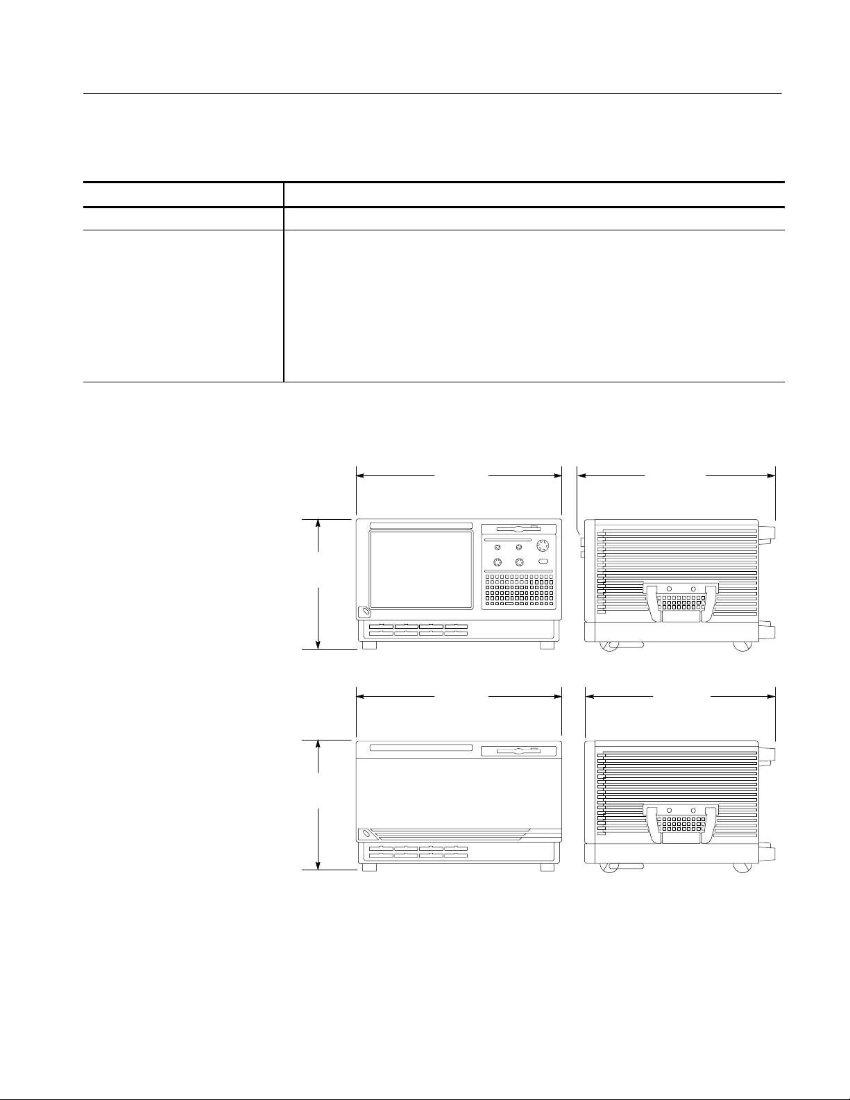
Table 1- 15: TLA600 mechanical characteristics
Characteristic Description
Overall Dimensions See Figure 1--1 on page 1--13 for overall chassis dimensions
Weight Includes empty accessory pouch and front cover
Specifications
TLA614, TLA624,
18.1 Kg (40 lbs)
TLA613 and TLA623
TLA612, TLA622,
18 Kg (39.75 lbs)
TLA611 and TLA621
TLA604 and TLA603 17.6 Kg (38.75 lbs)
TLA602 and TLA601 17.5 Kg (38.5 lbs)
281.94 mm
(11.10 in)
457.20 mm
(18.00 in)
421.64 mm
(16.60 in)
281.94 mm
(11.10 in)
Figure 1- 1: Dimensions of the TLA600 series logic analyzer
TLA600 Series Logic Analyzer Service Manual
457.20 mm
(18.00 in)
414.02 mm
(16.30 in)
1- 13
Page 36
Specifications
Table 1- 16: Atmospheric characteristics
Characteristic Description
Temperature:
Operating and nonoperating
Operating (no media in floppy disk drive):
+5_Cto+50_C, 15_C/hr maximum gradient, non-condensing
(derated 1_C per 1000 ft above 5000 foot altitude)
Nonoperating (no media in floppy disk drive or CD ROM drive):
-- 2 0 _Cto+60_C, 15_C/hr maximum gradient, non-condensing.
Relative Humidity:
Operating and nonoperating
Altitude:
Operating and nonoperating
Operating (no media in floppy disk drive or CD ROM drive):
20% to 80% relative humidity, non-condensing. Maximum wet bulb temperature: +29_C
(derates relative hum idity to approximately 22% at +50_C).
Nonoperating (no media in floppy disk drive or CD ROM drive):
8% to 80% relative humidity, non-condensing. Maximum wet bulb temperature: +29_C (derates
relative humidity to approximately 22% at +50_C).
Operating:
To 10,000 ft (3040 m), (derated 1_C per 1000 ft (305 m) above 5000 ft
(1524 m) altitude)
Nonoperating:
40,000 ft (12190 m).
Table 1- 17: Certifications and compliances
Category Standards or description
EC Declaration of Conf ormity -EMC
Meets intent of Directive 89/336/EEC for Electromagnetic Compatibility. Compliance was
demonstrated to the following specifications as listed in the Official Journal of the European
Communities:
EN 61326 EMC requirements for Class A electrical equipment for
measurement, control and laboratory use.
1
IEC 61000--4--2 Electrostatic discharge immunity (Performance criterion B)
IEC 61000--4--3 RF electromagnetic field immunity (Performance criterion A)
IEC 61000--4--4 Electrical fast transient / burst immunity (Performance criterion B)
IEC 61000--4--5 Power line surge immunity (Performance criterion B)
IEC 61000--4--6 Conducted RF immunity (Performance criterion A)
IEC 61000--4--11 Voltage di ps and interruptions immunity (Performance criterion B)
EN 61000--3--2 AC power line harmonic emissions
Australia / New Zealand
Declaration of Conformity-EMC
1
Emissions which exceed the levels required by this standard may occur when this equipment is connected to a test
object.
1- 14
Complies with EMC provision of Radiocommunications Act per the following standard(s):
AS/NZS 2064.1/2 Industrial, Scient ific, and Medical Equipment: 1992
TLA600 Series Logic Analyzer Service Manual
Page 37
Table 1- 17: Certifications and compliances (Cont.)
g
g
y
Category Standards or description
Specifications
EC Declaration of Conf ormity -Low Voltage
Canadian Certification CAN/CSA C22.2 No. 1010. 1 Safety requirements for el ectrical equipment for measurement,
Installation (Overvoltage)
Category
Pollution Degree A measure of the contaminat es that could occur in the environment around and within a product.
Safety Certification Compliance
Equipment Type Test and measuring
Safety Class Class 1 (as defined in IEC 1010-1, Annex H) -- grounded product
Overvoltage Category Overvoltage Category II (as defined in IEC 1010-1, Annex J)
Pollution Degree Pollution Degree 2 (as defined in IEC 1010-1). Note: Rated for indoor use only.
Compliance was demonstrated to the f ollowing specification as listed in the Official Journal of the
European Communities:
Low Voltage Directive 73/23/EEC, amended by 93/68/EEC
EN 61010-1/A2:1995 Safety requirements for electrical equipment for measurement
control and laboratory use.
EN 61010-2-031:1994 Particular requirements for hand-held probe assemblies for
electrical measurement and test equipment.
EN 61010-2-032:1995 Particular requirements for hand-held current clamps for electrical
measurement and test equipment.
control, and laboratory use.
Terminals on this product may have different installation (overvoltage) category designations. The
installation categories are:
CAT III Distribution-level mains (usually permanently connected). Equipment at this level is
typically in a fixed industrial location.
CAT II Local-level mains (wall sockets). Equipment at this level includes appliances, portable
tools, and similar products. Equipment is usually cord-connected.
CAT I Secondary (signal level) or battery operated circuits of electronic equipment.
Typically the internal environment inside a product is considered to be the same as the external.
Products should be used only in the environment for which they are rated.
Pollution Degree 2 Normally only dry, nonconductive pollution occurs. Occasionally a
temporary conductivity that is caused by condensation must be
expected. This location is a typical office/home environment.
Temporary condensation occurs only when the product is out of
service.
TLA600 Series Logic Analyzer Service Manual
1- 15
Page 38
Specifications
Table 1- 18: Adjustment/verification fixture specifications
Characteristic Description
Instrument characteristics
Number of data outputs
For P6417 and P6418 Probes 18 grouped in two groups of eight and one group of two
For P6434 Probes 36 grouped in one connector
Number of setup and hold clock outputs
For P6417 Probes and P6418 Probes Two grouped in one group of two
For P6434 Probes One clock
Number of DC threshold outputs
For P6417 Probes and P6418 Probes 16 grouped in two groups of eight and one group of two
For P6434 Probes 36 grouped in one connector
External clock in External clock input provided by user through a BNC connector
DC threshold input External input provided by user through a BNC connector
DC power in Provided by a wall transformer DC power supply (9 V to 12 V DC)
VDDDC level (typical) +5 V referenced to V
VDDto analog ground level (typical) +2 V referenced to ground (GND)
VDDswitcher noise (typical) 50 mV
(measured at C17)
p-p
n Internal clock frequency 50.065 MHz ±0.01%
Output electrical characteristics
Data/clock output amplitude 10K Motorola ECLinPS family outputs
DC threshold output Output equals user-applied input
Input requirements
External Clock input 1.0 V
centered around the fixture ground. Specification is valid between 5 MHz
p-p
and 210 MHz
DC power in 12 Volts DC at 1.5 A. Power is provided by one of the following power supply wall
plugs: 119-4855-00, 119-4856-00, 119-4859-00, and 119-4857-00
DC threshold input Input not greater than ±5 V ground referenced
Output timing
n Data output (channel-to-channel skew) 50 ps (all channels within 50 ps relative to each other)
n Setup clock output timing Adjusted for +3.0 ns (setup) ±100 ps, referenced to one of the data outputs
n Hold clock output timing Adjusted for 0.0 ns (hold) ±100 ps, referenced to one of the data outputs
Minimum data output pulse width Adjusted for 2.0 ns ±100 ps (jumpered in minimum pulse width mode)
Fuse rating
Recommended replacement fuse 1.5 AF, 125 V, Tektronix part number 159-5009-00
EE
1- 16
TLA600 Series Logic Analyzer Service Manual
Page 39
Operating Information
This chapter contains basic information about your logic analyzer. Refer to the
Tektronix Logic Analyzer Family User Manual andtotheonlinehelpformore
information on how to use your logic analyzer.
TLA600 Series Logic Analyzer Description
The TLA600 series is a high-performance line of logic analyzers. There are two
basic styles: one style has an internal display, and the other uses an external
display (TLA60X Series) as shown in Figure 2--1.
Internal and
external display
Figure 2- 1: TLA600 series logic analyzers
TLA600 Series Logic Analyzer Service Manual
External
display only
(TLA60X Series)
2- 1
Page 40
Operating Information
User Interface
The external display only version uses an external mouse and keyboard for
controls. The internal and external display version uses both front panel controls
and an external mouse and keyboard.
Color LCD Display
Front Panel Keypad and
Knobs
USB Port
The internal and external logic analyzer features a 10.4-inch diagonal,
600 X 800, flat-panel color LCD display.
The front panel of the logic analyzer includes a QWERTY keyboard, and five
front panel knobs. The keypad is active simultaneously with an external
keyboard.
The front panel knobs include a large multi-function knob and four smaller
positioning/scale knobs. The multi-function knob is used primarily for incrementing and decrementing values in selected menu boxes. The four positioning
and scale knobs provide scrolling of logic analyzer displays.
There is one USB (universal serial bus) port. The USB port can be used for any
USB complaint device. Table 2--1 lists the pin assignments of the USB connector.
Table 2- 1: USB (universal serial bus) pin assignments
Pin number Pin function Pin number Pin function
A1 Vcc B1 Vcc
A2 ADATA-- B2 BDATA--
2- 2
Mouse Port
Keyboard Port
PC Card Port
A3 ADATA+ B3 BDATA+
A4 GND B4 GND
The logic analyzer supports an external pointing device. The mouse connector is
a standard six-pin, PS/2-compliant DIN connector. The mouse port can be
connected to an external, standard PS/2-compliant three-button mouse.
The logic analyzer has an external keyboard port. The keyboard connector is a
standard six-pin PS/2-compliant DIN connector. The keyboard port can be
connected to an external, standard PS/2-compliant keyboard.
There are two PCMCIA card slots that support an industry standard Type I, II, or
III PCMCIA PC card.
TLA600 Series Logic Analyzer Service Manual
Page 41

Operating Information
Hard Disk Drive
CD-ROM Drive
Floppy Disk Drive
Memory SO DIMMs
External I/O BNCs
There is one hard drive. Because of the speed at which the PC industry evolves,
the hard disk drive is subject to change. This service manual lists the size of the
hard disk drive available at the time the product was introduced. Consult your
Tektronix Sales Representative for the maximum hard disk drive available.
The logic analyzer has one CD-ROM drive.
The logic analyzer has one standard 1/2 inch drive that supports 3.5 inch, 1.44
MByte, high-density/double-sided floppy disk media.
The logic analyzer utilizes 168-pin DIMM modules. The memory devices must
have gold pins.
Refer to the specifications for memory parameters.
The logic analyzer has four test I/O BNC connectors on the rear panel. These
connectors are as follows:
SYSTEM TRIG IN Connect or. The System Trigger Input is a TTL-compatible
signal input that is user definable in software. The System Trigger Input utilizes
a BNC connector. Refer to your user manual for additional information.
SYSTEM TRIG OUT Connect or. The System Trigger Output is a TTL-compatible
output signal that is user definable in software. The System Trigger Output
utilizes a BNC connector. Refer to your user manual for additional information.
EXTERNAL SIGNAL IN Connector. The External Signal Input is a TTL-compatible
input signal that is user definable in software. The External Signal Input utilizes
a BNC connector. Refer to your user manual for additional information.
EXTERNAL SIGNAL OUT Connector. The External Signal Output is a TTL-compatible output signal that is user definable in software. The System Trigger
Output utilizes a BNC connector. Refer to your user manual for additional
information.
TLA600 Series Logic Analyzer Service Manual
2- 3
Page 42

Operating Information
SVGA Port
COM Port
The SVGA OUT port supports an industry standard SVGA color monitor. The
connector is a 15-pin, sub-D SVGA-compliant connector. See Table 2--2 for pin
assignments.
Table 2- 2: SVGA OUT pin assignments
Pin number Pin function Pin number Pin function
1 RED 2 GRN
3 BLU 4 NC
5 GND 6 GND
7 GND 8 GND
9 (KEY) 10 GND
11 NC 12 DDC DAT
13 HSYNC 14 VSYNC
15 DDD CLK
The COM port is an industry standard RS-232 serial port.
Table 2- 3: COM OUT pin assignments
Pin number Pin function Pin number Pin function
1 DCD 2 RXD
3 TXD 4 DTR
5 GND 6 DSR
7 RTS 8 CTS
9 Ring Indicator
2- 4
TLA600 Series Logic Analyzer Service Manual
Page 43

Operating Information
LPT Port
The LPT port is a parallel printer port. This parallel printer port supports
standard Centronics mode, Enhanced Parallel Port (EPP), or Microsoft highspeed mode (ECP) and utilizes a 36-pin high density Centronics-compliant
connector. See Table 2--4 for pin assignments.
Table 2- 4: LPT (par allel interface) pin assignments
Pin number Pin function Pin number Pin function
1 BUSY 19 GND
2 SLCT 20 GND
3 ACK* 21 GND
4 ERR* 22 GND
5 PE 23 GND
6 D0 24 GND
7 D1 25 GND
8 D2 26 GND
9 D3 27 GND
10 D4 28 GND
11 D5 29 GND
12 D6 30 GND
13 D7 31 GND
14 INIT* 32 GND
15 STB* 33 GND
16 SLIN* 34 GND
17 AFD* 35 GND
18 HI 36 H1
See IEEE specification P1284-C for pin connection definitions for other modes
TLA600 Series Logic Analyzer Service Manual
2- 5
Page 44

Operating Information
Operating System and Application Interface
The logic analyzer comes with the Microsoft Windows operating system
factory-installed. Operations and capabilities when running on the logic analyzer
are the same as with Microsoft Windows running on a high-performance
personal computer. Windows Help is available from the Start menu of the
Windows Task Bar. Early versions of the logic analyzer came with Windows 98,
while newer version (with system software version 4.0 and up) come with
Windows 2000 Professional.
The logic analyzer also comes with the TLA series application software
configured at the factory to launch after the logic analyzer boots up and the
operating system is running. The TLA series application software controls data
acquisition and processing by the logic analyzer. The TLA series application
software is included with the product.
You can also install other Windows-based software as needed to work with your
applications.
Online Help
Much of the user information for operating the logic analyzer is available
through online help. Refer to the online help for information on the individual
menus, icons, and fields within each window.
Refer to your Microsoft Windows documentation for information on using
Windows help.
Software Installation and Removal
The following procedures describe loading and unloading the performance
verification and adjustment software. Refer to the Tektronix Logic Analyzer
Family User Manual for information on installing or removing any other
software. It is recommended you have ≥10 MB of free space on the hard drive
before installing the software. The Performance Verification software is located
on Disk 1 of the Tektronix Logic Analyzer Family Application Software CD.
2- 6
TLA600 Series Logic Analyzer Service Manual
Page 45

Operating Information
NOTE. This installation program uses parameters you supply to create a custom
start-up file in your hard disk directory.
The batch file enables the software to configure your instrument properly before
it runs the program.
1. Power on the instrument.
2. Exit the Application.
Verify the Software
Version
Verify Directories
Install the Software
If your logic analyzer already has performance verification and adjustment
software loaded on it, you must verify that the version is the same as the version
printed on Disc 1 of the Tektronix Logic Analyzer Family Application Software CD.
If the version of the performance verification and adjustment software loaded on
your logic analyzer is an earlier version, you must delete the earlier version
before you can load the newer version.
If your logic analyzer already has a directory named Tekcats or Temptek on the
hard drive, the software installation cannot be completed. Follow these instructions to verify the directory is not present:
1. Select Start → Search → For Files or Folders.
2. In the “Search for files or folders named:” box, type “Tekcats” or “Temptek”
and then click the Search Now button to sesarch for either directory .
3. If either directory is found follow the instructions under Removing the
Software to remove the software and the directories.
Follow these instructions to install the performance verification and adjustment
software.
1. Close all open windows on the desktop.
2. Insert Disk 1 of the Tektronix Logic Analyzer Family Application Software
CD in the CD-ROM drive.
3. Click the My Computer Icon and double-click the CD-ROM drive.
4. Double-click the TLA Performance Verification folder.
5. Double-click on the Logic Analyzer PV folder and then double-click the
Disk1 folder.
6. Double-click the Setup.exe icon to begin the installation program.
TLA600 Series Logic Analyzer Service Manual
2- 7
Page 46

Operating Information
7. Follow the on-screen instructions to install the software on the hard disk.
8. After the installation is complete, go back to the TLA Performance
Verification folder on the CD.
This completes the software installation procedure.
Removing the Software
Use the following procedure to remove the performance verification and
adjustment software from the instrument. These steps are necessary when you
want to upgrade the PV software.
1. Open Windows Explorer and then locate and select the C:\Tekcats folder.
2. Go to the File menu and select Delete to delete the folder.
3. Repeat steps 1 and 2 to delete the Temptek folder if it exists.
4. Select Start → Settings → Taskbar & Start Menu.
5. Click the Advanced tab followed by the Advanced button.
6. Open the following directory path under Documents and Settings:
All Users → Start Menu → Programs
7. Locate and delete the TLA Performance Verification item.
2- 8
TLA600 Series Logic Analyzer Service Manual
Page 47

Theory of Operation
This section provides a brief overview of the board level theory of operation for
the logic analyzer. Refer to page 9--1 for a functional block diagrams.
Hardware
The logic analyzer contains the following major components:
Controller Board
Riser Board
Interface Board
An NLX mother board based on an Intel Celeron microprocessor and the 810E
chip set runs the operating system software in the TLA600 series logic analyzers.
This controller provides the hardware connections to the following devices:
H USB port
H PS2 mouse and keyboard
H Serial port
H Parallel port
H SVGA port
The NLX mother board receives power through a riser board connected to the
interface board. The mother board communicates with the interface board
through the PCI bus and the USB bus.
The Riser board connects the NLX mother board to the interface board. It also
has the connections to the hard disk drive and to the CD-ROM drive.
The interface board contains the circuitry to interface the PCI bus to the VXI bus
to route the external signal and trigger I/O signals to generate the CLK10
reference. This generates the display signals for the internal display system (if
used).
IA Bus
Power Distribution (Rear)
TLA600 Series Logic Analyzer Service Manual
The IA bus allows communication with the instrument. This is a message-based
system that allows SCPI commands sent from the NLX/Interface controller to
the LPU circuitry on the acquisition board.
This board connects the power supply to the Interface board and to the acquisition board.
3- 1
Page 48

Theory of Operation
Power Distribution (Front)
Power Supply
Front Panel Keyboard
Display
Mechanical Chassis
This board is an additional connection between the power supply and the
acquisition board.
The power supply provides all voltages and currents to the logic analyzer. In
addition to the main power supply, the interface board generates the --2 V and
--5 V needed for proper operation.
This board contains the front panel keypad and five control knobs. The circuitry
is connected to the interface board through a USB bus.
The internal display is a 10.4-inch diagonal active matrix thin-film-transistor
(TFT) liquid crystal display with a built-in back light similar to the TLA700
Portable Mainframe. The back light can be dimmed to 60% of its value through a
custom Tektronix screen saver to extend its life and prevent the burning of the
screen. The color LCD is supported by an external DC switching regulator board
to provide the back light high voltage and a display adaptor board which
connects the interface board to the display.
The mechanical chassis provides the mechanical support structure for the
instrument, and includes the cooling system, the EMI shielding system, and all
the subsystems.
Probe Interface
The logic analyzer connects to the target system through the probe interface.
There is one connector per probe for a maximum of eight connectors depending
on the instrument configuration.
The logic analyzer can use the following probes to connect to the target system:
H P6417
H P6418
H P6434
Depending on the instrument configuration, you can connect up to eight P6417
or P6418 general purpose probes, or up to four P6434 high-density probes.
3- 2
TLA600 Series Logic Analyzer Service Manual
Page 49

Acquisition
Theory of Operation
The acquisition board is mounted on the bottom of the instrument. It has several
custom CMOS ASCIs ,several full custom bipolar ICs, RAM for the acquisition
memory, and other miscellaneous circuitry. The acquisition board takes the data
acquired by the probes, determines when to clock the data into memory, and
communicates the acquisition information with the rest of the instrument.
The acquisition board also contains the LPU circuitry which interfaces between
the VXI bus and the acquisition circuitry.
No manual calibration or adjustments exist. All calibration is done by software
but requires the adjustment/verification fixture (671-3599-XX) to be used for
proper deskew. The calibration procedures are described in the Adjustment
Procedures chapter.
TLA600 Series Logic Analyzer Service Manual
3- 3
Page 50

Theory of Operation
3- 4
TLA600 Series Logic Analyzer Service Manual
Page 51

Performance Verification: Logic Analyzer
This chapter contains procedures for functional verification, certification, and
performance verification procedures for the TLA600 Series Logic Analyzers and
the adjustment/verification fixture. Generally, you should perform these
procedures once per year or following repairs that affect certification.
Summary Verification
Functional verification procedures verify the basic functionality of the instrument inputs, outputs, and basic instrument actions. These procedures include
power-on diagnostics, extended diagnostics, and manual check procedures.
These procedures can be used for incoming inspection purposes.
Certification procedures certify the accuracy of an instrument and provide a
traceability path to national standards. Calibration data reports are produced for
the logic analyzer modules as output from the performance verification and
adjustment software. In some cases, you will be required to manually fill out
certification data. For those cases, you can make copies of the calibration data
report included with this manual, and then fill out the reports with the data that
you obtain from the procedures.
Performance verification procedures confirm that a product meets or exceeds the
performance requirements for the published specifications documented in the
Specifications chapter of this manual. Refer to Figure 4--1 on page 4--2 for a
graphic overview of the procedures.
Adjustment procedures check for, and if necessary , correct any adjustment errors
discovered when performing functional or performance verification procedures.
The adjustment procedures for the logic analyzer modules are controlled by
software while the procedures for the adjustment/verification fixture require
manual intervention. Some of the adjustment procedures for the logic analyzer
modules also require manual intervention to move probes or change test
equipment settings.
The performance verification and adjustment software is provided on the product
CD-ROM. If you have not already done so, refer to Software Installation and
Removal beginning on page 2--6 for instructions on installing the performance
verification and adjustment software.
TLA600 Series Logic Analyzer Service Manual
4- 1
Page 52
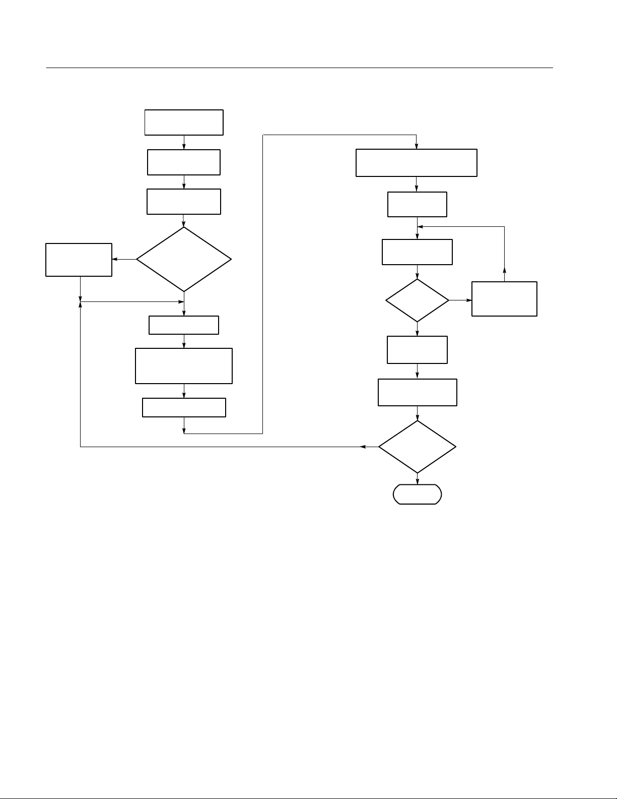
Performance Verification: Logic Analyzer
Determine equipment
to certify.
Use
Tektronix-supplied
probes.
Go to appropriate
procedure(s).
Gather required tes t
equipment.
No
with customer to
remove/reconnect probes
from System
Under Test?
Select procedure.
Configure instrument as
described in proc edure.
Set up test equipment.
Is it OK
Yes
Allow instrument and equipment to
warm up (30 minutes).
Load PV/Adjust
software.
Perform procedure
using software.
Do tests
pass?
No
Yes
Print Calibration
Data Report.
Create necessary
Calibration Certificate.
No
Are
all certifications
complete?
Repair or adjust
equipment as
required.
Figure 4- 1: Calibration/certification procedure flow chart
4- 2
Yes
Done
TLA600 Series Logic Analyzer Service Manual
Page 53

Performance Verification: Logic Analyzer
Test Equipment
The procedures use external, traceable signal sources to directly test characteristics that are designated as checked (n)intheSpecifications chapter of this
manual. Table 4--1 shows the required equipment list; the equipment is required
for the performance verification procedures and adjustment procedures for the
logic analyzer modules and for the adjustment/verification fixture.
Table 4- 1: Test equipment
Item number and description Minimum requirements Example
1. Mainframe TLA600 Series Logic Analyzer --
2. Adjustment/verification fixture,
with one of the following
Power Supplies:
USA/CAN
Europe
Japan
United Kingdom
3. Oscilloscope 1 GHz bandwidth Delay time accuracy ±25
4. DSO probes Two required, with < one-inch ground leads Tektronix P6243 or P6245 probe, with accesso-
5. 1X probe One required, with < one-inch ground leads Tektronix P6101B probe, with accessories
6. Logic analyzer probes Two required Tektronix P6417 or P6418 Logic Analyzer probes
7. High density logic analyzer
probe (optional)
8. Frequency counter Frequency range: 1 GHz Tektronix DC508
9. Digital multimeter with leads DCV accuracy: 0.1% from --10 V to +100 V Tektronix DMM 900 Series
10. Connector, dual-banana Female BNC-to-dual banana Tektronix part number 103-0090-XX
11. Voltage reference Accuracy: ≤0.01% Data Precision 8200
12. Capacitor
13. Adapter, N-to-BNC Male type N-to-female BNC Tektronix part number 103-0045-XX
14. Shorting jumpers Strip of 10, 2-wide Tektronix part number 131-5829-XX
15. Cable, precision 50 Ω coaxial 50 Ω, 36 in, male-to-male BNC connectors Tektronix part number 012-0482-XX
16. Signal Generator 250 MHz Tektronix SG503
1
The capacitor is installed across the Data Precision 8200 output terminals to reduce noise. If your voltage reference
produces <4 mVp-p of noise, external noise reduction is not necessary.
1
12 V, 1.5 A
12 V, 1.5 A
12 V, 1.5 A
12 V, 1.5 A
ppm over any ≥ 1 ms interval
One required Tektronix P6434 Logi c Analyzer probe
0.1 F, 200 V Tektronix part number 283-0189-XX
Tektronix part number 671-3599-XX
Tektronix part numbers:
119-4855-XX
119-4856-XX
119-4859-XX
119-4857-XX
Tektronix TDS 784D
ries
TLA600 Series Logic Analyzer Service Manual
4- 3
Page 54
Performance Verification: Logic Analyzer
Functional Verification
This section contains instructions for performing the functional verification
procedures for the TLA600 Series Logic Analyzers; functional verification
procedures for the adjustment/verification fixture begin on page 4--21. These
procedures provide an easy way to check the basic functionality of the LA
modules and probes.
Table 4--2 lists the functional verification procedures available for the logic
analyzer and probes.
Table 4- 2: TLA600 Functional verification procedures
Instrument Procedure
Logic Analyzer Power-up diagnostics No
Logic Analyzer Extended diagnostics No
Logic Analyzer Mainframe diagnostics No
Adjustment/verification
fixture required
Logic Analyzer CheckIt Utilities No
P6417, P6418, or P6434 logic
analyzer probes
Signal Input check Yes
NOTE. Running the extended diagnostics will invalidate any acquired data. If
you want to save any of the acquired data, do so before running the extended
diagnostics.
If any check within this section fails, refer to the Troubleshooting sectioninthe
Maintenance chapter of this manual for assistance. Failed tests indicate the
instrument needs to be serviced.
This procedure provides a functional check only. If more detailed testing is
required, perform the Performance Verification Procedure after completing this
procedure. Perform these tests whenever you need to gain confidence that the
instrument is operating properly.
You will need the following equipment to complete the functional verification
procedures:
Equipment required Cable, 50 Ω coaxial (item 15)
4- 4
Prerequisites Warm-up time: 30 minutes
TLA600 Series Logic Analyzer Service Manual
Page 55

Performance Verification: Logic Analyzer
Power-On Diagnostics
Extended Diagnostics
During power-on, the power-on diagnostics are run. If any power-on diagnostics
fail, the instrument displays the Calibration and Diagnostics property sheet.
Complete the following steps to run the extended diagnostics:
NOTE. Perform the following steps to complete the functional verification
procedures. Before beginning this procedure, be sure that no active signals are
applied to the logic analyzer. Certain diagnostic tests will fail if signals are
applied to the probe during the test.
1. Power on the instrument and wait for the system application to start.
2. Go to the System menu and select Calibration and Diagnostics.
3. Verify that all power-on diagnostics pass.
4. Click the Extended Diagnostics tab.
5. Select All Modules, All Tests (top line) and click the Run button on the
property sheet.
The diagnostics software performs each one of the tests listed in the menu
under the module selection. All tests that displayed an Unknown status will
change to a Pass or Fail status depending on the outcome of the tests.
6. Scroll through the test results for the instrument and verify that all tests pass.
NOTE. If Extended Diagnostics fail, run the self calibration for the logic
analyzer and then rerun Extended Diagnostics. To run the self calibration, click
the Self Calibration tab, click the Run button, and follow any on-screen
instructions.
TLA600 Series Logic Analyzer Service Manual
4- 5
Page 56
Performance Verification: Logic Analyzer
Mainframe Diagnostics
CheckIt Utilities
The TLA Mainframe Diagnostics check the functionality of the instrument. To
run these diagnostics, do the following steps:
1. Exit the TLA application.
2. Click the Windows Start button.
3. Select Programs from the Start menu.
4. Select Tektronix Logic Analyzer from the Programs menu.
5. Select Tektronix TLA Mainframe Diagnostics from the Tektronix Logic
Analyzer menu.
6. Run the mainframe diagnostics. Connect the BNC cable when requested.
When the TLA Mainframe Diagnostics are run, a Mainframe Diagnostics
Warning dialog box appears. Clicking OK will initiate a SYSRESET, which will
invalidate any acquired data.
CheckIt Utilities is a comprehensive software application used to check and
verify the operation of the PC hardware in the instrument. You can test most of
the hardware in the instrument using selected tests with CheckIt Utilities. You
don’t need to run all of the tests, since CheckIt Utilities has tests for PC
hardware that is not present in the logic analyzer.
Checking the Cooling Fan
Operation
Probe Functional
Verification
CAUTION. Before starting the CheckIt Utilities, install a test floppy disk in the
floppy disk drive and a test CD in the CD-ROM drive.
To run CheckIt, follow these instructions:
1. Exit the TLA application.
2. Click the Windows Start button.
3. Select Programs.
4. Select CheckIt Utilities.
5. Run the selected tests that you are interested in.
Power on the instrument and inspect the side of the instrument to verify that all
six cooling fans are rotating.
The following procedure checks the basic operation of the probes by verifying
that the probes recognize signal activity at the probe tips.
4- 6
TLA600 Series Logic Analyzer Service Manual
Page 57
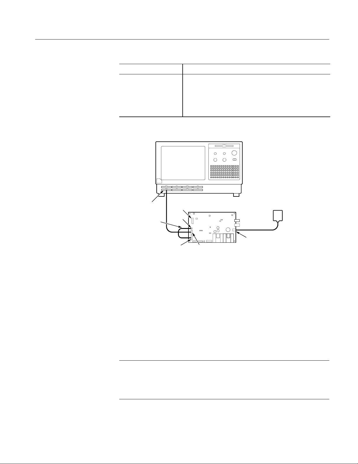
Performance Verification: Logic Analyzer
Equipment required Adjustment/verification fixture (item 2 )
Prerequisites Warm-up time: 30 minutes for instrument and test equipment
P6417, P6418, or P6434 probe connected to the instrument
Test equipment connected as shown in Figure 4--2
Diagnostics pass
1
Do not mix probes; only one type of probe can be functionally verified at a time.
1
Test Procedure
C2/C3/CK3
Channel/Group
Clock channel
Adjustment/verification
J5
J3
J1
fixture
J2
Fixture supply
J26
Figure 4- 2: Probe functional verification test setup
Perform the following steps to complete the probe functional verification
procedure:
1. Ensure that the jumper at J15 on the adjustment/verification fixture is in the
INT position to select the internal 50.065 MHz clock.
2. Open the Setup window and click the Set Thresholds button to display the
Probe Threshold dialog box.
3. Adjust the threshold level to 700 mV for all channels.
NOTE. These procedures assume a P6418 or P6417 probe is used.
If you are use a P6434 probe, use J5, the Data Out connector on the adjustment/
verification fixture to verify probe functionality. Observe proper polarity: pin 1
to pin 1.
TLA600 Series Logic Analyzer Service Manual
4- 7
Page 58

Performance Verification: Logic Analyzer
4. Refer to Figure 4--2 and connect the podlets of the acquisition probe to J1
and J2 on the fixture. Ensure that you connect the ground side of the podlets
to the ground side of the connectors.
5. Connect the single clock (CK n) or the qualifier (Q n) channel to one of the
J3 CLK OUT connector pairs on the fixture.
6. Return to the Setup window and click the Show Activity button to display
the Activity Monitor.
7. Verify that the Activity Monitor shows activity on all probe channels
connected to the test fixture.
Figure 4--3 shows an example of the Activity Monitor. Note the signal
activity for clock CK3 and data channels for the C3(7-0) and C2(7-0) groups.
Also note that there is no activity on the other groups because the probe
podlets are not connected to a signal source (the channels are all high).
4- 8
Figure 4- 3: Activity monitor
8. Verify that none of the connected channels are stuck high or stuck low.
9. Disconnect the probe from the fixture and the instrument.
10. Repeat the steps for any remaining probes.
11. Close the Activity Monitor.
12. Return the threshold levels to their former values in the Probe Threshold
dialog box.
13. This completes the probe functional verification procedure.
TLA600 Series Logic Analyzer Service Manual
Page 59

Certification
Use the performance verification procedures to check the accuracy of the system
clock and to perform the DC Threshold test. The instrument is certifiable if these
parameters meet specifications. Running the system clock test requires you to
record the test data on a copy of the Calibration Data Report (found at the end of
this chapter). You can print out a software-generated Calibration Data Record for
the DC Threshold test after running the performance verification and adjustment
software.
Other specifications can also be verified by running the complete performance
verification procedures.
Performance Verification Instructions
This section contains procedures to verify that the TLA600 series instruments
perform as warranted. V erify instrument performance whenever the accuracy or
function of your instrument is in question, or as part of an annual calibration/certification. As a general rule, these tests only need to be done once a year.
Performance Verification: Logic Analyzer
Prerequisites
You will use the performance verification and adjustment software to complete
most of the performance verification procedures. You will check the accuracy of
the 10 MHz system clock manually without the software.
The performance verification and adjustment software contains instructions and
control programs for testing each characteristic designated as checked (n)inthe
Specifications chapter of this manual.
These procedures ask for the serial number of the instrument under test. Record
the serial number and state speed of the instrument (located on a label on the
right side of the back panel) so that you can enter the information when
prompted by the software.
The tests in this section comprise an extensive, valid confirmation of performance and functionality when the following requirements are met:
H The logic analyzer application must not be running.
H The performance verification and adjustment software must be loaded. Refer
to Software Installation and Removal on page 2--6.
H The logic analyzer must have been operating for at least 30 minutes at an
ambient temperature between +20_ C and +30_ C.
H The logic analyzer must have been last adjusted at an ambient temperature
between +20_ C and +30_ C.
TLA600 Series Logic Analyzer Service Manual
4- 9
Page 60

Performance Verification: Logic Analyzer
H The logic analyzer must be in an operating environment within the limits
described in the Specifications chapter of this manual.
Procedure Overview
You will begin the procedures by performing the 10 MHz System Clock
(CLK10) test using manual checks and recording the results on copies of the
Calibration Data Report. You will then use the performance verification and
adjustment software to complete the remaining tests.
When using the performance verification and adjustment software, you will
connect external test equipment to the logic analyzer in response to prompts on
the screen. You will connect the test signals and then instruct the program to
continue. The performance verification and adjustment software automatically
selects the instrument settings and determines the results of each test.
The results of the tests are recorded in a temporary file and are available upon
test completion for completing test records for certification. To obtain partial test
information you can also run individual tests or selected groups.
NOTE. The self calibration (Self_Cal) test must run successfully before the other
tests are performed. The remaining tests can then be performed in any order.
Before testing an instrument following repair, you must first complete the
adjustment procedure.
The performance verification and adjustment software contains the tests shown
in Table 4--3. Each test verifies one or more parameters. All of the tests check
characteristics that are designated as checked (n)intheSpecifications chapter.
By running a full PV sequence, you will verify the performance of the logic
analyzer.
4- 10
Table 4- 3: TLA600 PV/Adjust software perform ance verification tests
Performance verification test name Specification tested
1. System clock (CLK10)
2. FPV_DC_THRESHOLD
3. FPV_SETUP_0F Setup time
4 FPV_HOLD_0F Hold time
5. FPV_MAXSYNC Maximum synchronous clock rate
1
Certifiable parameter
1
1
Signal output check
Threshold accuracy
TLA600 Series Logic Analyzer Service Manual
Page 61

Performance Verification: Logic Analyzer
Table 4--4 lists the additional characteristics that are designated as checked (n)
in the Specifications chapter of this manual. These characteristics are indirectly
tested by the performance verification and adjustment software tests named in
the table.
Table 4- 4: TLA600 characteristics indirectly checked by the performance
verification and adjustment software performance verification tests
Performance verification test name Specification tested
1. FPV_SETUP_0F Minimum recognizable word
2 FPV_HOLD_0F Minimum recognizable word
3. All tests Trigger state sequence rate
4. All tests, and Extended Diagnostics Internal sampling period
1
When the setup and hold time tests are both performed, the setup and hold
window size is indirectly verified.
2
When the setup and hold time tests are both performed, the channel-to-channel
skew is indirectly verified.
3
When all of the tests are performed, including Extended Diagnostics, the
internal sampling period is indirectly verified.
1,2
1,2
3
In addition to the basic system setup, you will need some of the equipment
shown in Table 4--1 on page 4--3 to complete the performance verification
procedures.
Each procedure includes a table that calls out the equipment used. Use Table 4--1
for equipment specifications. If you substitute equipment, always choose
instruments that meet or exceed the minimum requirements specified.
TLA600 Series Logic Analyzer Service Manual
4- 11
Page 62

Performance Verification: Logic Analyzer
Using the Software
The software consists of executable software files. Use the following steps to
start and run the software:
1. Allow the instruments to warm up for at least 30 minutes before beginning
the procedure.
2. Quit all applications including the TLA application.
3. Select Start → Programs → TLA Performance Verification.
4. To run the performance verification and adjustment software, select
LA 6XX PV.
5. Follow the instructions on the screen to enter the name you want to appear in
the User Name field as shown below. This name will appear on the
Calibration Data Reports.
6. The program lists several different instruments, referred to as DUT (Device
Under Test). Enter the number corresponding to the instrument type that you
want to test; then click Enter to continue.
The screen will display an error message if the DUT chosen does not match
the installed DUT.
7. Click Enter to continue.
8. Enter the complete serial number of the DUT (for example, B010100). Click
Enter to continue.
If you select no, a prompt asks you to enter the serial number again.
4- 12
TLA600 Series Logic Analyzer Service Manual
Page 63

Performance Verification: Logic Analyzer
9. The program lists sequences for PV (performance verification) and ADJ
(adjustments). Enter a number to select which sequence you want and click
Enter to continue.
10. If an instrument is being tested, the program lists the different probe types
available for testing. Enter the appropriate number corresponding to your
probe and then click Enter to continue.
11. Enter the operating temperature in degrees C (entries in the range of 20 to 30
degrees are valid). Click Enter to continue.
12. Enter the operating humidity as a percentage (0% to 100% entries are valid).
Click Enter to continue.
13. Determine which sequence to run:
H RUN FULL SEQUENCE runs the entire sequence from beginning to
end. This is the recommended selection.
H RUN PARTIAL SEQUENCE runs part of the full sequence. The
sequence runs from the selected starting point to the end of the sequence.
Using the Interrupt Button
H SELECT TEST(S) runs only the selected tests. To run a single test, enter
the test number. To run multiple tests, enter a comma-separated list of
numbers or a hyphen-separated list of numbers.
Enter the number next to your choice and click Enter to continue.
14. Follow the on-screen instructions to connect and adjust test equipment.
15. When testing is completed, disconnect the test equipment.
While the program is running, you can interrupt the program to rerun a test, start
over, or to exit the program by clicking the Interrupt button (shown below).
The program will then provide a list of choices. Enter the number next to the
choice that you want and click Enter.
NOTE. If you interrupt a test before it has completed, you must restart the test to
obtain valid test data.
Some tests such as Internal Cal do not allow interrupts. If you s top these tests
using more aggressive methods, you may have to reboot the instrument.
TLA600 Series Logic Analyzer Service Manual
4- 13
Page 64

Performance Verification: Logic Analyzer
Obtaining Test Results
The results of all tests can be stored in a file on the hard disk. You can view the
test results, print the test results to a printer, or save the test results in another file
on the hard disk. The software stores the test results in a file containing the
module name and serial number (for example, TLA621.B020123). The file is
located under the following path: C:\Tekcats\Rpt.
NOTE. If you want to save the content of the Report file, you must rename or
copy the Report file using the Windows file utilities such as Explorer.
The Report file will be overwritten the next time you run the performance
verification and adjustment software and print or view a new set of test data.
After completing a full or partial test sequence (or just before you exit the
program) you can generate the test data and write it to a file. You have the option
of printing the file, viewing the file on screen, or transferring the file to another
directory or host computer.
You can print the test data directly from the program. Ensure that a printer is
connected to your logic analyzer and follow the on-screen instructions to print
the test results.
If a printer is not available, you can view the test results directly from the screen,
or you can copy the test results to a different file or folder/host computer for
future use.
Field Adjust/PV Software
Housekeeping
Troubleshooting
The performance verification and adjustment software creates data log files (.dlf
files) that store program data. The .dlf files are used by the performance
verification and adjustment software to generate the view data and print out
options. Each .dlf file is identified by the product serial number; for example,
B010100.dlf. The files are stored in the Tekcats folder under each TLA6xx
folder. To conserve disk space, you must occasionally delete the .dlf files.
If any tests fail, use the following steps to troubleshoot the problems:
1. Check all test equipment for improper or loose connections.
2. Check that all test equipment is powered on and has the proper warm-up
time.
3. If you are using the adjustment/verification fixture, verify the LED is
lighted, the jumper positions match the on-screen instructions, and the
external connections are correct. (See Figure 4--4 for jumper locations.)
4. Rerun mainframe or module diagnostics and module adjustment.
5. Run the tests a second time to verify the failure.
4- 14
TLA600 Series Logic Analyzer Service Manual
Page 65
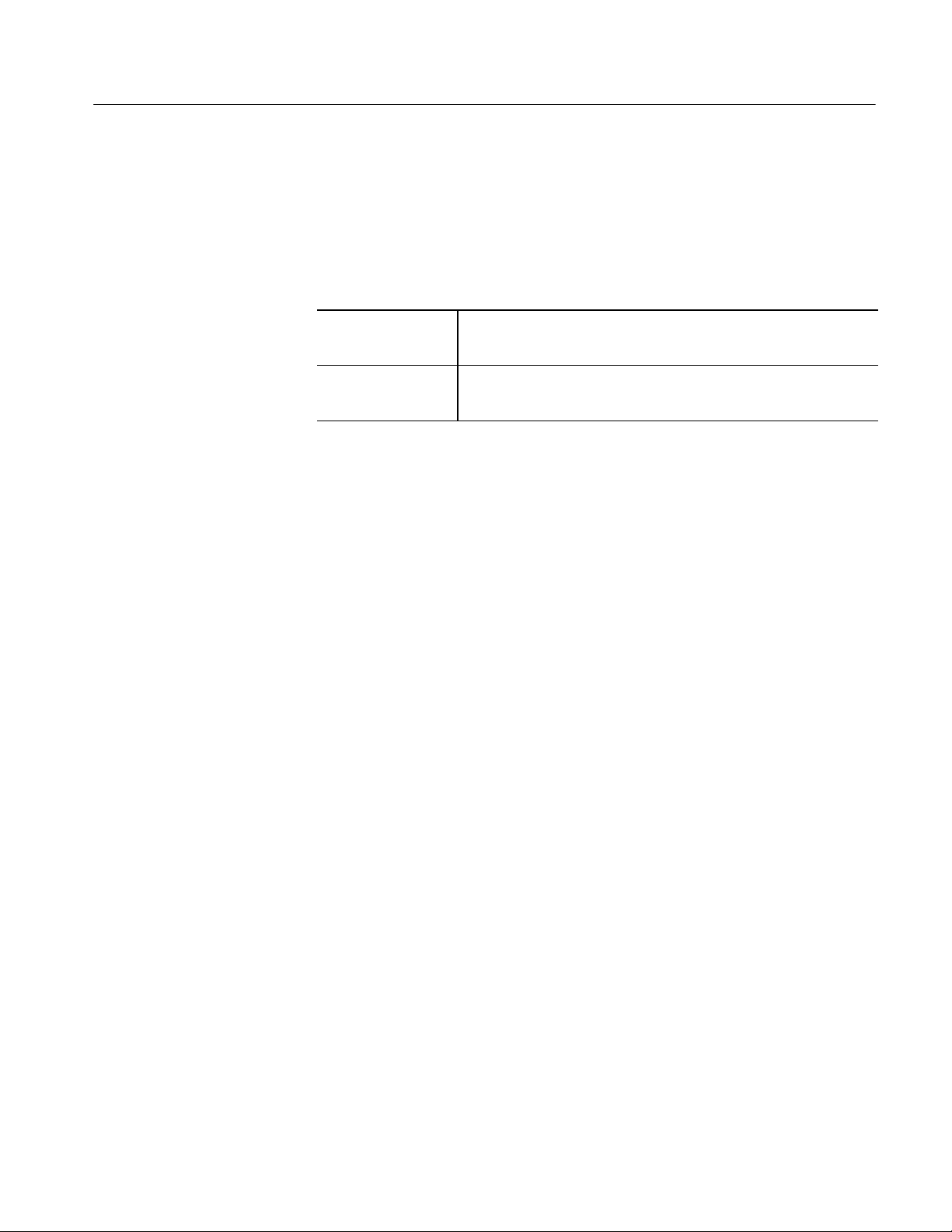
Performance Verification Tests
Use the following tables and figures to set up and execute each procedure.
Performance Verification: Logic Analyzer
Procedure 1: 10MHz
System Clock (CLK10)
This procedure verifies the accuracy of the system clock.
Equipment required
Prerequisites Warm-up time: 30 minutes for the logic analyzer and test equipment
1. Connect the frequency counter to the External Signal Out TTL BNC
connector on the back of the instrument.
2. Verify that the Tektronix Logic Analyzer application is running.
3. Go to the System window and select System Configuration from the System
menu.
4. In the System Configuration dialog box, select 10 MHz Clock from the list
of routable signals in the External Signal Out selection box and click OK.
5. Verify that the output frequency at the External Signal Out TTL connector is
10 MHz ±1 kHz. Record the measurement on the Calibration Data Report.
6. In the system configuration dialog box, reset the External Signal Out signal
to None.
Frequency counter (item 8)
Precision BNC cable (item 15)
All diagnostics pass
7. Disconnect the frequency counter.
TLA600 Series Logic Analyzer Service Manual
4- 15
Page 66
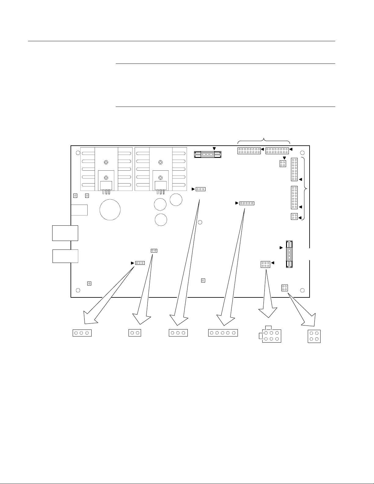
Performance Verification: Logic Analyzer
NOTE. The illustrations in the following procedures show P6418 or P6417
probes. If you have a P6434 probe, use J14 on the adjustment/verification fixture
for the DC Threshold test; all other procedures using the P6434 probe use J5,
the Data Out connector. When using either type of probe, always observe correct
polarity (GND to GND, pin 1 to pin 1).
Threshold
External
Clock in
P6434
Threshold out
J14
J15
J10 J8
J22
J18
J26
J19
J17
J9
J11
DC in
in
P6417 and P6418 Threshold out
J6 J7
J20
J1
J16
J13
J2
J3
J5
J4
P6417
and
P6418
Data out
P6434
Data out
J17
Hold/Setup
select
SetupHold
clocked on falling edge
Jumper removed:
clocked on rising edge
J19
Jumper installed:
Ext/Int
Clock select
J15
IntExt
12345
J16
Deskew
Figure 4- 4: Adjustm ent/verification fixture connections and jumper locations
4- 16
TLA600 Series Logic Analyzer Service Manual
Deskew
Probe
setup
6
J13
P6434
Deskew/Probe setup
1
Clock
Clock
GND
GND
J4
Setup/Hold
Clock out
Page 67
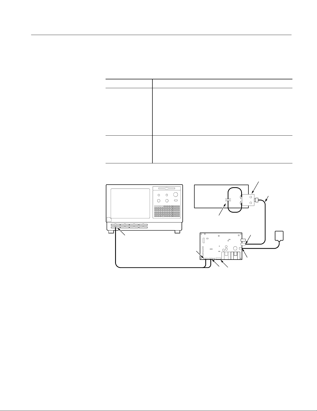
Performance Verification: Logic Analyzer
Procedure 2:
FPV_DC_Threshold
This procedure verifies the DC Threshold Accuracy of the logic analyzer. This
test is performed once and applies to all channels of the instrument.
SW test name FPV_DC_Threshold
Equipment required
Prerequisites Warm-up time: 30 minutes
Adjustment/verification fixture and fixture supply (item 2)
Voltage reference (item 11)
Precision BNC cable (item 15)
Dual banana-to-BNC adapter (item 10)
Capacitor, 0.1 F (item 12)
Test equipment connected as shown in Figure 4--5
Diagnostics and SELF_CAL pass
Voltage reference
+
--
Dual banana-toBNC adapter
BNC cable
0.1 F Capacitor
Fixture
supply
C2/C3/CK3
Channel/Group
Adjustment/verification
J7
fixture
J6
J14 Threshold out P6434
J22
J26
Figure 4- 5: FPV_DC_Threshold t est setup
1. If the logic analyzer application is running, quit the application. Verify that
all of the prerequisites listed previously are met for the procedure.
2. Run the performance verification and adjustment software as described in
Using the Software on page 4--12. Run the C:\Tekcats\Tla_la program and
then select the correct module type and the PV test option.
3. Follow the on-screen instructions to run each portion of the test for each
parameter of the instrument.
4. Verify that all of the tests pass.
TLA600 Series Logic Analyzer Service Manual
4- 17
Page 68
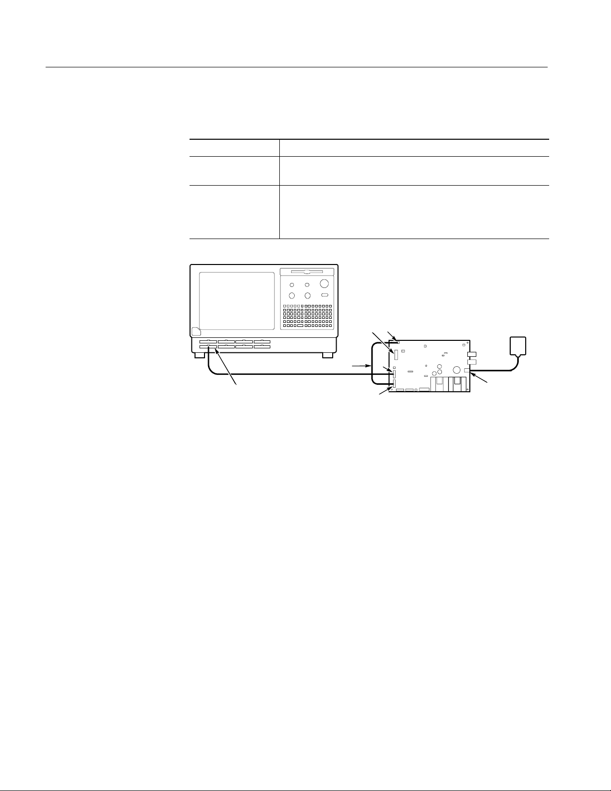
Performance Verification: Logic Analyzer
Procedure 3:
FPV_Setup_0F
This procedure verifies the setup time of the logic analyzer.
SW test name FPV_Setup_0F
Equipment required
Prerequisites Warm-up time: 30 minutes
C2/C3/CK3
Channel/Group
Adjustment/verification fixture and fixture supply (item 2)
Test equipment connected as shown in Figure 4--6
Diagnostics and SELF_CAL pass
Adjustment/verification
J4
Clock channel
J5
J2
J1
fixture
Fixture supply
J26
Figure 4- 6: Initial FPV_Setup_0F test setup
1. If the logic analyzer application is running, quit the application and verify
that all of the prerequisites listed previously are met for the procedure.
2. Follow the on-screen instructions to run each portion of the test for each
parameter of the instrument.
3. Verify that all of the tests pass. If a test fails, run the Deskew routine as
described on page 5--6, then rerun the test.
4- 18
TLA600 Series Logic Analyzer Service Manual
Page 69
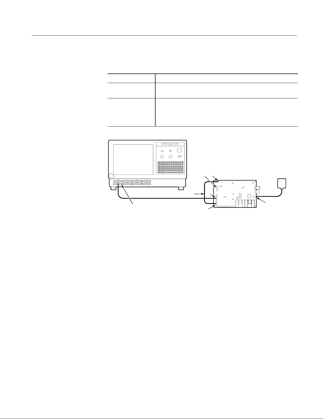
Performance Verification: Logic Analyzer
Procedure 4:
FPV_Hold_0F
This procedure verifies the hold time of the logic analyzer.
SW test name FPV_Hold_0F
Equipment required
Prerequisites Warm-up time: 30 minutes
C2/C3/CK3
Channel/Group
Adjustment/verification fixture and fixture supply (item 2)
Test equipment connected as shown in Figure 4--7
Diagnostics and SELF_CAL pass
Adjustment/verification
J4
Clock channel
J5
J2
J1
fixture
Fixture supply
J26
Figure 4- 7: Initial FPV_Hold_0F test setup
1. If the logic analyzer application is running, quit the application and verify
that all of the prerequisites listed previously are met for the procedure.
2. Follow the on-screen instructions to run each portion of the test for each
parameter of the instrument.
3. Verify that all of the tests pass. If a test fails, run the Deskew routine as
described on page 5--6, then rerun the test.
TLA600 Series Logic Analyzer Service Manual
4- 19
Page 70
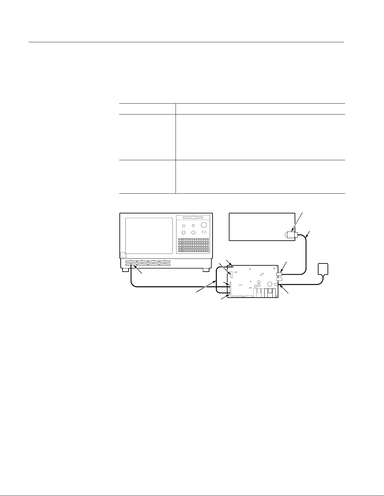
Performance Verification: Logic Analyzer
Procedure 5:
FPV_Maxsync
This procedure checks the Maximum Synchronous Clock Rate and the Trigger
State Sequence Rate of the logic analyzer. This test is performed once and
applies to all channels of the instrument.
SW test name FPV_Maxsync
Equipment required
Prerequisites Warm-up time: 30 minutes
Adjustment/verification fixture and fixture supply (item 2)
Sine wave generator (item 16)
BNC cable (it em 15)
Adapter, N-to-BNC (item 13)
Test equipment connected as shown in Figure 4--8
Diagnostics and SELF_CAL pass
Sine wave generator
Adjustment/verification
J4
J5
fixture
J18
Type N-to-BNC
adapter
BNC cable
Fixture
supply
C2/C3/CK3
Channel/Group
Clock channel
J2
J26
J1
Figure 4- 8: FPV_Maxsync test setup
1. If the logic analyzer application is running, quit the application and verify
that all of the prerequisites listed previously are met for the procedure.
2. Follow the on-screen instructions to run the test.
3. Verify that all of the tests pass.
After completing the performance verification procedures, obtain a copy of the
test results and verify that all parameters are within the allowable specifications
as listed in the Specifications chapter of this manual.
4- 20
TLA600 Series Logic Analyzer Service Manual
Page 71

Performance Verification: Adjustment/Verification Fixture
This section contains the functional verification procedures, performance
verification procedures, and certification procedures for the adjustment/verification fixture. A calibration data report for the adjustment/verification fixture is
also available at the end of this chapter where you can record the certifiable
parameters.
Test Equipment
These procedures use external, traceable signal sources to directly test characteristics that are designated as checked (n)intheSpecifications chapter of this
manual. Table 4--1 on page 4--3 shows the required equipment list for the
procedures in this section. Each piece of equipment used in these procedures is
referenced by an item number to the equipment listed in Table 4--1.
Functional Verification
The functional verification procedure consists of the following checks:
Power Supply
H Basic power supply verification
H External clock input circuit verification
This procedure provides a functional check only. If more detailed testing is
required, perform the performance verification procedure, which begins on
page 4--25, after completing this procedure.
Use the following procedure to verify that the fixture power supply is functional.
1. Plug the fixture power supply included with the adjustment/verification
fixture into an appropriate socket and plug the DC connector into J26.
2. The LED adjacent to J26 should light. This indicates the input power supply
is functioning properly.
TLA600 Series Logic Analyzer Service Manual
4- 21
Page 72
Performance Verification: Ajustment/Verification Fixture
External Clock Input
Use the following procedure to verify the external clock input circuit is dividing
the input frequency by two and routing this clock signal to the proper output
connectors. This test provides a basic functionality check of the adjustment/verification fixture.
Parameter tested Ext ernal clock input
Equipment
required
Prerequisites Warm-up time: 30 minutes for adjustment/verific ation fixture and test
Sine wave generator (item 16)
Precision BNC cable (item 15)
Oscilloscope (item 3)
Oscilloscope probe (item 4)
equipment
1. Set the jumper positions as called out in the table. R efer to Figure 4--9 on
page 4--23 for jumper locations.
Jumper Jumper name Jumper setting
J13 P6434 Setup & Hold/Deskew select Disconnected
J15 Clock selection EXT
J16 Deskew 1-2 and 4-5 connected
J17 Setup/hold select Disconnected
J19 Clock polarity select Disconnected
2. Connect the sine wave generator to J18, EXT CLK IN, on the adjustment/
verification fixture.
3. Set the generator output to 210 MHz, 1 V p-p.
4. Set up the oscilloscope by pressing Setup, Factory Setup, and then press OK
Confirm Factory Init to return the oscilloscope to default conditions.
4- 22
TLA600 Series Logic Analyzer Service Manual
Page 73
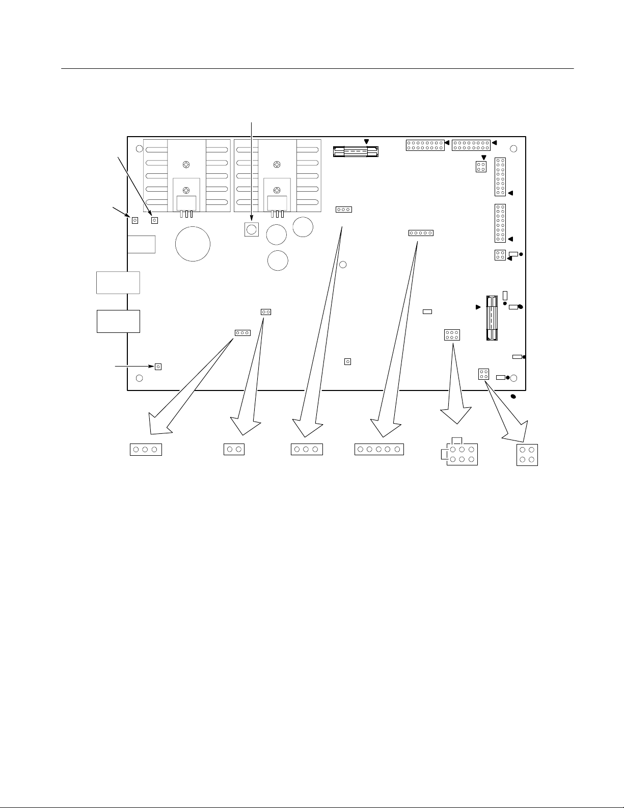
R38 (VDDadjust )
Performance Verification: Ajustment/Verification Fixture
J10 (VDD)
Threshold
External
Clock in
J9 ( GND )
J8 (VEE)
DC in
in
J22
J18
J26
J17
Setup/Hold
select
SETUPHOLD
Jumper installed:
clocked on falling edge
Jumper removed:
clocked on rising edge
J19
J17
J19
J15
Ext/Int
Clock select
J15
INTEXT
J14
12345
J16
DESKEW
J6 J7
J16
J13
DESKEW
PROBE
SETUP
6
J13
P6434
Deskew/Probe setup
J20
J1
J2
J3
R321
J5
R39
J4
R127
1
Clock
Clock
R85
R67
Denotes ground
side of resistor
GND
GND
J4
Setup/Hold
Clock out
Figure 4- 9: Adjustm ent/verification fixture detail
5. Set up the oscilloscope as listed below.
a. Set up the CH1 Vertical menu as follows:
H Coupling DC/50 Ω
H Fine Scale 200 mV/div
H Position --3.32 div
TLA600 Series Logic Analyzer Service Manual
4- 23
Page 74

Performance Verification: Ajustment/Verification Fixture
b. Set up the Horizontal menu as follows:
H Time Base Main
H Record Length 5000
H Horizontal Scale Main Scale @ 5 ns/div
c. Set up the Trigger menu as follows:
H Source CH1
H Coupling DC
H Slope +
H Level 700 mV
H Mode Normal
d. Set up the Measure menu as follows:
H Select Measurement for CH1 Frequency
H Gating Off
e. Set up the Cursor menu as follows:
H Function Off
f. Set up the Acquire menu as follows:
H Acquisition Mode Sample
H Repetitive Signal On
6. Using the oscilloscope and the custom probe adapter shown in Figure 4--10
on page 4--26, verify that the output frequency at J1 pin-2 on the adjustment/
verification fixture is 105 MHz.
7. Press the Run/Stop button to stop the acquisition.
8. Disconnect the test equipment from the adjustment/verification fixture.
9. This completes the functional verification procedures for the adjustment/ver-
ification fixture.
4- 24
TLA600 Series Logic Analyzer Service Manual
Page 75

Certification
The internal system clock and clock output timing are checked for accuracy. The
adjustment/verification fixture accuracy is certifiable if these parameters meet
specifications.
The procedure is described in the performance verification section, beginning on
page 4--25. Make a copy of the Calibration Data Report at the end of this chapter
and then record the results on the copy.
Performance Verification
This section contains procedures to verify the accuracy of the adjustment/verification fixture.
Performance Verification: Ajustment/Verification Fixture
Prerequisites
Tests Performed
The tests in this section provide a valid confirmation of performance and
functionality when the following requirements are met:
H The adjustment/verification fixture must have been operating for a warm-up
period of at least 30 minutes, and must be operating at an ambient temperature between +20_ C and +30_ C.
H The adjustment/verification fixture must have been last adjusted at an
ambient temperature between +20_ C and +30_ C.
H The adjustment/verification fixture must be in an environment within the
same limits as for the logic analyzer, described in the Specifications section
of the Tektronix Logic Analyzer Family User Manual.
These tests should be performed once every two years.
Each test verifies one or more parameters.
Table 4- 5: Adjustment/verification fixture performance verification tests
Test name Specification tested
Power supply V
Internal clock frequency
Data skew
Hold time
Setup time
1
1
1
1
Certifiable parameter
1
DD
50.065 MHz
Less than 50 ps between any 2 channels
0.0 ns
+3.0 ns
TLA600 Series Logic Analyzer Service Manual
4- 25
Page 76

Performance Verification: Ajustment/Verification Fixture
Custom Probe Tip Adapter
A custom probe tip adapter is used in these procedures to ensure signal integrity
when making precise measurements. The primary function of the custom probe
tip adapter is to minimize the length of the ground lead of the probe. Build the
custom probe tip adapter as shown in Figure 4--10.
Socket,
Tektronix P/N
131-0258-00
.025 in Berg pin,
Tektronix P/N
131-1426-00
Adjust this distance to span
a 1206 SMT component,
such as R85 on the adjust-
ment/verification fixture.
Solder pin to
socket frame
Figure 4- 10: Probe tip adapter detail
4- 26
TLA600 Series Logic Analyzer Service Manual
Page 77

Test Procedures
Performance Verification: Ajustment/Verification Fixture
Refer to Figure 4--11 on page 4--28 for component and test point locations used
in the following procedures. Table 4--6 on page 4--28 describes the functions of
the jumpers used on the fixture for verifying the performance of the Tektronix
logic analyzers. The jumpers are also used in these procedures.
All procedures must be followed sequentially. If any single step fails or is out of
calibration, then upon retest, you must start at the first test and follow this
section through from start to finish sequentially.
Power Supply Checks
The following procedures check the DC power supply characteristics.
Parameter tested Power supply
Equipment
required
Prerequisites Warm-up time: 30 minutes for adjustment/verific ation fixture and test
DMM with test leads (item 9)
equipment
1. Plug the fixture supply into an appropriate AC outlet and connect the
DC plug to J26 on the adjustment/verification fixture.
2. Connect the DMM (--) lead to J8 (V
3. Connect the DMM (+) lead to J10 (V
).
EE
) and verify a voltage reading of
DD
+5.00 V ±100 mV.
4. Leave the (+) lead of the DMM connected to J10 (V
) and connect the
DD
DMM (--) lead to J9 (GND). Verify a voltage reading of +2.00 V ±30 mV.
TLA600 Series Logic Analyzer Service Manual
4- 27
Page 78

Performance Verification: Ajustment/Verification Fixture
R38 (VDDadjust )
J10 (VDD)
Threshold
External
Clock in
J9 ( GND )
J8 (VEE)
DC in
in
J22
J18
J26
J17
Setup/Hold
select
SETUPHOLD
Jumper installed:
clocked on falling edge
Jumper removed:
clocked on rising edge
J19
J17
J19
J15
Ext/Int
Clock select
J15
INTEXT
J14
12345
J16
DESKEW
J6 J7
J16
J13
DESKEW
PROBE
SETUP
6
J13
P6434
Deskew/Probe setup
J20
J1
J2
J3
R321
J5
R39
J4
R127
1
Clock
Clock
R85
R67
Denotes ground
side of resistor
GND
GND
J4
Setup/Hold
Clock out
Figure 4- 11: Adjustment/verification fixture detail
Table 4- 6: Adjustment/verification fixture jumper settings
Jumper Jumper name Jumper function
J13 P6434 Deskew/probe
setup
J15 Clock selection Determines whether the internal clock (50.065 MHz) or the
J16 Deskew Selects between minimum or nominal pulse width
J17 Setup/hold select Determines whether checking setup time or hold time
J19 Clock polarity sel ect Selects polarity of the clock for setup and hold testing
4- 28
Determines whether checking set up/hold or deskew for the
P6434 probe (J5)
external clock (J18, BNC) will drive the circuitry
TLA600 Series Logic Analyzer Service Manual
Page 79

Performance Verification: Ajustment/Verification Fixture
Verify Internal Clock
Frequency
Use the following procedure to verify the internal clock frequency.
Parameter tested I nternal clock frequency
Equipment
required
Prerequisites Warm-up time: 30 minutes for adjustment/verific ation fixture and test
Frequency counter (item 8)
equipment
1. Set the jumper positions as listed in the table.
Jumper Jumper name Jumper setting
J13 P6434 Deskew/probe setup 3-5 connected
J15 Clock selection INT
J16 Deskew 2-3 and 4-5 connected
J17 Setup/hold select HOLD
J19 Clock polarity select Removed
2. Using the frequency counter, measure the oscillator frequency at pin J1-2.
The frequency should match what is listed on the Calibration Data report.
3. Record this measurement on the Calibration Data Report.
TLA600 Series Logic Analyzer Service Manual
4- 29
Page 80
Performance Verification: Ajustment/Verification Fixture
Verify Data Output
Channel-to-Channel Skew
Use the following procedure to verify the channel-to-channel data skew.
Parameter tested Channel-t o-channel data skew
Equipment
required
Prerequisites Warm-up time: 30 minutes for adjustment/verific ation fixture and test
Oscilloscope (item 3)
2 DSO probes (item 4)
Custom probe tip adapter (see Figure 4--10, page 4--26)
equipment
1. Set the jumper positions as listed in the following table.
Jumper Jumper name Jumper setting
J13 P6434 Deskew/probe setup 3-5 connected
J15 Clock selection INT
J16 Deskew 2-3 and 4-5 connected
J17 Setup/hold select HOLD
J19 Clock polarity select Removed
2. Set up the oscilloscope by pressing Setup, Factory Setup, and then OK Confirm Factory Init to return the oscilloscope to default conditions.
3. Set up the oscilloscope as listed below.
a. Set up the CH1 and CH2 Vertical menu as follows:
H Coupling DC/50 Ω
H Fine Scale 200 mV/div
H Position --3.00 div CH1
H Position --3.32 div CH2
b. Set up the Horizontal menu as follows:
H Time Base Main
H Record Length 5000
H Horizontal Scale Main Scale @ 2 ns/div
4- 30
TLA600 Series Logic Analyzer Service Manual
Page 81

Performance Verification: Ajustment/Verification Fixture
c. Set up the Trigger menu as follows:
H Source CH2
H Coupling DC
H Slope +
H Level 700 mV
H Mode Normal
d. Set up the Measure menu as follows:
H Select Measurement for CH1 Measure
H Gating On
e. Set up the Cursor menu as follows:
H Function V Bars
f. Set up the Acquire menu as follows:
H Acquisition Mode Average 90
H Repetitive Signal On
4. Connect CH2 of the oscilloscope to J4-2 on the adjustment/verification
fixture.
5. Select Deskew from the Vertical menu of the oscilloscope.
NOTE. Observe proper polarity when doing the following steps. See Figure 4--9
on page 4--23 to identify the ground side of the components being measured.
6. Connect the CH1 probe of the oscilloscope to the custom probe tip adapter
and measure the signal across R85.
7. Use the large knob at the upper right of the oscilloscope panel to adjust delay
until the leading edges of the two waveforms coincide and the displayed
value of CH1-CH2 delay is averaged around 0 ±25 ps.
8. Move the CH1 probe to R321, R67, and R39 and press the Run/Stop button
to start an acquisition. Verify that the CH1-CH2 delay between any two
measurements does not exceed 90 ps.
9. The maximum difference between the three measured values represents the
channel-to-channel skew. Record this difference on the Calibration Data
Report.
TLA600 Series Logic Analyzer Service Manual
4- 31
Page 82

Performance Verification: Ajustment/Verification Fixture
Verify Hold Clock Output
Timing
Use the following procedure to verify the hold time.
Parameter tested Hold time
Equipment
required
Prerequisites Warm-up time: 30 minutes, adjustment/verification fixture and test
Oscilloscope (item 3)
2 DSO probes (item 4)
Custom probe tip adapter (see Figure 4--10, page 4--26)
equipment
1. Set the jumper positions as listed in the table.
Jumper Jumper name Jumper setting
J13 P6434 Deskew/probe setup 1-3 and 5-6 connected
J15 Clock selection INT
J16 Deskew 1-2 and 4-5 connected
J17 Setup/hold select HOLD
J19 Clock polarity select Disconnected
2. Set up the oscilloscope by pressing Setup, Factory Setup, and then OK
Confirm Factory Init to return the oscilloscope to default conditions.
3. Set up the oscilloscope as listed below.
a. Set up the CH1 Vertical menu as follows:
H Coupling DC/50 Ω
H Fine Scale 200 mV/div
H Position --3.00 div CH1
H Position --3.32 div CH2
b. Set up the Horizontal menu as follows:
H Time Base Main
H Record Length 5000
H Horizontal Scale Main Scale @ 2 ns/div
4- 32
TLA600 Series Logic Analyzer Service Manual
Page 83

Performance Verification: Ajustment/Verification Fixture
c. Set up the Trigger menu as follows:
H Source CH2
H Coupling DC
H Slope +
H Level 700 mV
H Mode Normal
d. Set up the Measure menu as follows:
H Select Measurement for CH1 Measure
H Gating On
e. Set up the Cursor menu as follows:
H Function V Bars
f. Set up the Acquire menu as follows:
H Acquisition Mode Average 90
H Repetitive Signal On
4. Connect the CH2 probe of the oscilloscope to J1-2 on the adjustment/verification fixture.
5. Select Deskew from the Vertical menu.
NOTE. Observe proper polarity when performing the following steps.
See Figure 4--9 on page 4--23 to identify the ground side of the components being
measured.
6. Connect the CH1 probe of the oscilloscope to the custom probe tip adapter
and measure the signal across R67.
7. Begin the acquisition by pressing the Run/Stop button.
8. Use the large knob at the upper right of the panel to adjust delay until the
leading edges of the two waveforms coincide and the displayed value of
CH1-CH2 delay is averaged around 0.
9. Connect the CH1 probe to R127. Verify the CH1-CH2 delay is averaged
around 0 ns ±100 ps.
TLA600 Series Logic Analyzer Service Manual
4- 33
Page 84
Performance Verification: Ajustment/Verification Fixture
10. The CH1-CH2 delay represents the hold time at R127. Record the hold time
at R127 on the Calibration Data Report.
11. Connect the C H1 probe to R321. Verify the CH1-CH2 delay is averaged
around 0 ns ±100 ps.
12. The CH1-CH2 delay represents the hold time at R321. Record the hold time
at R321 on the Calibration Data Report.
Verify Setup Clock Output
Timing
Use the following procedure to verify the setup time.
Parameter tested Setup time
Equipment
required
Prerequisites Warm-up time: 30 minutes for adjustment/verific ation fixture and test
Oscilloscope (item 3)
2 DSO probes (item 4)
Custom probe tip adapter (see Figure 4--10, page 4--26)
equipment
1. Set the jumper positions as listed in the table.
Jumper Jumper name Jumper setting
J13 P6434 Deskew/probe setup 1-3 and 5-6 connected
J15 Clock selection INT
J16 Deskew 1-2 and 4-5 connected
J17 Setup/hold select SETUP
J19 Clock polarity select Disconnected
4- 34
2. Set up the oscilloscope by pressing Setup, Factory Setup, and then OK
Confirm Factory Init to return the oscilloscope to default conditions.
3. Set up the oscilloscope as listed below.
a. Set up the CH1 Vertical menu as follows:
H Coupling DC/50 Ω
H Fine Scale 200 mV/div
H Position --3.00 div CH1
H Position --3.32 div CH2
TLA600 Series Logic Analyzer Service Manual
Page 85

Performance Verification: Ajustment/Verification Fixture
b. Set up the Horizontal menu as follows:
H Time Base Main
H Record Length 5000
H Horizontal Scale Main Scale @ 2 ns/div
c. Set up the Trigger menu as follows:
H Source CH2
H Coupling DC
H Slope +
H Level 700 mV
H Mode Normal
d. Set up the Measure menu as follows:
H Select Measurement for CH1 Measure
H Gating On
e. Set up the Cursor menu as follows:
H Function V Bars
f. Set up the Acquire menu as follows:
H Acquisition Mode Average 90
H Repetitive Signal On
4. Connect the CH2 probe of the oscilloscope to J1 pin-2 on the adjustment/
verification fixture.
5. Select Deskew from the Vertical menu of the oscilloscope.
NOTE. Observe proper polarity when doing the following steps. See Figure 4--9
on page 4--23 to identify the ground side of the components being measured.
6. Connect the CH1 probe of the oscilloscope to the custom probe tip adapter
and measure the signal across R67.
7. Press the Run/Stop button to stop the acquisition and read the measurement.
8. Use the large knob at the upper right of the panel to adjust delay until the
leading edges of the two waveforms coincide and the displayed value of
CH1-CH2 delay is averaged around 0.
TLA600 Series Logic Analyzer Service Manual
4- 35
Page 86
Performance Verification: Ajustment/Verification Fixture
9. Set one of the vertical cursors before the leading edge of the CH 2 pulse, and
the other cursor after the leading edge of the CH 1 pulse.
10. Connect the CH1 probe to R127. Verify the CH1-CH2 delay is averaged
around 3.0 ns ±100 ps.
11. The CH1-CH2 delay represents the setup time at R127. Record the setup
time at R127 on the Calibration Data Report.
12. Connect the CH1 probe to R321. Verify the CH1-CH2 delay is averaged
around 3.0 ns ±100 ps.
13. The CH1-CH2 delay represents the setup time at R321. Record the setup
time at R321 on the Calibration Data Report.
Verify External Clock Input
Use the following procedure to verify the external clock input.
Parameter tested Ext ernal Clock Input
Equipment
required
Prerequisites Warm-up time: 30 minutes for adjustment/verific ation fixture and test
Frequency Counter (item 8)
Signal Generator (item 16)
Shorting Jumpers (item 14)
equipment
1. Set the jumper positions as listed in the table.
Jumper Jumper name Jumper setting
J13 P6434 Deskew/probe setup 1-3 and 5-6 connected
J15 Clock selection EXT
J16 Deskew 1-2 and 4-5 connected
J17 Setup/hold select SETUP
J19 Clock polarity select Disconnected
4- 36
2. Using the signal generator, insert a 225 MHz, 1 V
signal at J18 EXT CLK
p-p
IN.
3. Using the frequency counter, verify that the data is being output at a
112.5 MHz clocked rate at J1 and J2.
TLA600 Series Logic Analyzer Service Manual
Page 87
Calibration Data Report
TLA600 Logic Analyzer
Instrument model number:
Serial number: Certificate number:
Verification performed by: Verification dat e:
System Clock Test Data
Procedure
Characteristic Specification Tolerance
Clock frequency 10 MHz ±1 kHz (9.9990 MHz-10.0010 MHz) Page 4--15,
reference
Step 5
Incoming data Outgoing data
Page 88

Page 89

TLA600 Adjustment Procedures
This chapter contains procedures which use the performance verification and
adjustment software to adjust the TLA600 Series Logic Analyzers to within
factory specifications. The performance verification and adjustment software
contains instructions and control programs for adjusting the logic analyzer. The
software describes test equipment connections and settings, selects setup
parameters, and loads calibration constants into memory.
This chapter also contains adjustment procedures for the adjustment/verification
fixture which begin on page 5--9.
These procedures adjust the logic analyzer for conformance with the warranted
characteristics listed in the Specifications chapter of this manual.
Adjustments should be done after repair or when any performance verification
tests have failed.
Prerequisites
These procedures ask for the serial number of the instrument under test. You can
access the serial number through the logic analyzer application. In the application, go to the System menu, select System Properties, and click on the LA tab.
However, you must quit the application before continuing with the performance
verification and adjustment software procedures.
Only trained service technicians should perform this procedure after meeting the
following requirements:
H The logic analyzer application must not be running.
H The performance verification and adjustment software must be loaded. Refer
to Software Installation and Removal beginning on page 2--6.
H The logic analyzer requires a 30-minute warm-up time in a +20_ Cto
+30_ C environment before it is adjusted. Adjustments performed before the
operating temperature has stabilized may cause errors in performance.
TLA600 Series Logic Analyzer Service Manual
5- 1
Page 90

TLA600 Adjustment Procedures
Using the Software
This section describes how to perform adjustments using the performance
verification and adjustment software.
Performing the
Adjustments
Adjustment Sequences
and Dependencies
Adjustment After Repair
There are no manual adjustments for the logic analyzer. Instead, the performance
verification and adjustment software adjusts the instrument hardware using
external test equipment connections that you provide in response to prompts on
the screen.
Upon successful completion of each adjustment, the performance verification
and adjustment software automatically loads the new calibration data into
memory.
The performance verification and adjustment software allows you to run groups
of adjustments, or sequences. A sequence consists of one or more individual
adjustments. Normally you will perform a RUN FULL SEQUENCE, which
executes each adjustment in the proper order.
The performance verification and adjustment software also provides instructions
for running each adjustment individually. However, you should only perform
individual adjustments while troubleshooting.
You must perform a full adjustment sequence following replacement of any
circuit board.
Test Equipment
5- 2
In addition to the basic system setup, you will need some of the equipment
shown in Table 4--1 on page 4--3 in the Performance Verification chapter.
Each procedure includes a table that calls out the equipment used. Use Table 4--1
to identify required equipment specifications. If you substitute equipment,
always choose instruments that meet or exceed the minimum requirements
specified.
TLA600 Series Logic Analyzer Service Manual
Page 91
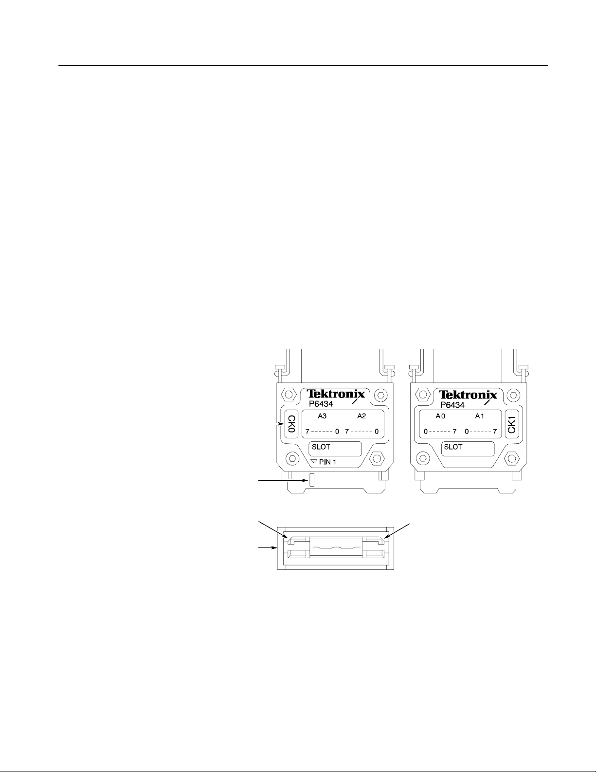
Adjustment Instructions
This section describes how to perform adjustments using the performance
verification and adjustment software.
TLA600 Adjustment Procedures
Using the PV/Adjust
Software
The performance verification and adjustment software contains instructions for
performing the adjustments. The basic steps for completing the procedures
follow:
1. Start the program, enter user and product identification information and
temperature and humidity.
2. If you are using P6417 or P6418 probes, label one probe as the Reference
Probe, and the other probe as the Probe Under Test.
3. If you are using a P6434 probe, label the probe channel group identified as
the pin 38 side as Probe A. Label the probe channel group identified as the
pin 1 side as Probe B, refer to Figure 5--1.
Pin 1 label
Recess on
pin1side
Beveled corners
End view
Figure 5- 1: P6434 probe detail
4. Select a full adjustment sequence.
5. Connect the test equipment.
TLA600 Series Logic Analyzer Service Manual
Pin1side
Pin38side
Pin38side
Beveled corners
5- 3
Page 92

TLA600 Adjustment Procedures
6. Set up the test equipment for the output signals described by on-screen
instructions and by the connection illustration for each test.
7. Run each adjustment step as instructed by following the on-screen prompts.
8. After completing all the adjustment steps, view the results to confirm that
the adjustment was successful.
Troubleshooting
Tests Performed
If any adjustments fail, use the following steps to troubleshoot the problems:
H Check all test equipment for improper or loose connections.
H Check that all test equipment is powered on and has the proper warm-up
time.
H Verify that the adjustment/verification fixture LED is lighted, the jumper
positions match the on-screen instructions, and the external connections are
correct.
H Rerun the diagnostics and self calibration (SELF_CAL).
H Run the adjustment procedures a second time to verify the failure.
The adjustment procedures check and adjust the following parameters of the
logic analyzer:
H SELF_CAL, an internal routine in the application software that adjusts
acquisition thresholds, internal module and signal timing.
H Deskew, an adjustment routine in the performance verification and adjust-
ment software which time-aligns all channels.
5- 4
NOTE. Do not mix probe types (P6417, P6418 and P6434) when performing the
deskew procedure.
TLA600 Series Logic Analyzer Service Manual
Page 93

Adjustment Procedures
Self Calibration
TLA600 Adjustment Procedures
Refer to the following procedures to identify the initial setup for each adjustment. Then follow the program instructions to complete the adjustments.
SELF_CAL is an internal routine that optimizes performance at the current
ambient temperature to maximize measurement accuracy. No external equipment
or user actions are needed to complete the procedure. The logic analyzer saves
data generated by the self calibration in memory. Passing the self calibration
provides a higher level of confidence of functionality.
NOTE. Performing the self calibration does not guarantee that all parameters
operate within limits. Operation within limits is achieved by performing the
adjustment procedures. Verification of operation within limits is accomplished by
performing the performance verification procedures.
TLA600 Procedure 1:
SELF_CAL
When to Perform the Self Calibration. You can run the self calibration at any time
during normal operation. To maintain measurement accuracy, perform the
self calibration if the following conditions occur:
H After repair and replacement of any circuit boards
H It has been a year since the last self calibration was run
Perform the following steps to run the SELF_CAL routine. Before beginning
this procedure, be sure that no active signals are applied to the instrument. Self
calibration can fail if signals are applied to the probe during the procedure.
Prerequisites Warm-up time: 30 minutes
Power-up diagnostics pass
1. Ensure that the logic analyzer has had a 30-minute warm up before attempting the self calibration, and that the logic analyzer application is running.
2. Disconnect any probes connected to the logic analyzer.
3. Select the Calibration and Diagnostics property sheet from the System menu.
4. Select the Self Calibration tab.
TLA600 Series Logic Analyzer Service Manual
5- 5
Page 94

TLA600 Adjustment Procedures
5. Click the Run button to start the self calibration.
The self calibration takes several minutes to complete, depending on the
number of channels in the instrument. Upon successfully completing the self
calibration, the status changes from Running to Calibrated, and the Date and
Time field is set to the present.
TLA600 Procedure 2:
Deskew
The deskew procedure is used to calibrate and adjust the timing alignment of the
probe data channels and receivers.
Perform the deskew procedure:
H Once a year
H If you have replaced the acquisition board (the probe constants are stored on
the acquisition board)
This procedure checks and adjusts the time alignment of all channels. There are
no manual adjustments.
SW test name Deskew
Equipment
required
Prerequisites Warm-up time: 30 minutes for the TLA600 and test equipment
Adjustment/verification fixture and fixture supply (item 2 )
Two P6417 or P6418 Logic Analyzer probes (item 6), OR
One P6434 Logic Analyzer probe (item 7)
Test equipment connected as shown in Figure 5--2
Diagnostics and SELF_CAL pass
5- 6
C2/C3/CK3
Channel/Group
Clock channel
Figure 5- 2: Initial deskew test setup
Adjustment/verification
J5
J3
J1
fixture
J2
Fixture
supply
J26
TLA600 Series Logic Analyzer Service Manual
Page 95

TLA600 Adjustment Procedures
1. If the logic analyzer application is running, quit the application.
2. Verify that all of the prerequisites listed previously are met for the procedure.
3. Run the performance verification and adjustment software as described in the
Running the LA and DSO Software on page 2 --6. Run the C:\Tekcats\Tla_la
program and select the correct options.
NOTE. These procedures assume that a P6418 or P6417 probe is being used. If
you are using a P6434 probe, use J5, the Data Out connector on the adjustment/
verification fixture for performing the deskew test. Observe proper polarity:
pin1topin1.
4. Follow the on-screen prompts to perform the adjustment procedure.
5. Verify no failures occur for each test.
If desired, you can print or save the results of the deskew adjustment operation.
However, this is not required for calibration. The file will be over written when
the next adjustment or performance verification sequence is run.
If failures do occur, confirm that diagnostics and SELF_CAL pass.
Completing the Adjustment Steps
After completing the adjustments, obtain a copy of the test results and verify that
all tests passed. Run the Performance Verification Procedures to verify that the
all parameters are within the allowable specifications.
TLA600 Series Logic Analyzer Service Manual
5- 7
Page 96

TLA600 Adjustment Procedures
5- 8
TLA600 Series Logic Analyzer Service Manual
Page 97
Adjustment/Verification Fixture Adjustments
This section contains the adjustment procedures for the adjustment/verification
fixture. Most of the adjustments consist of moving jumpers or wires that change
the delays at specific locations on the board. Once these jumpers have been set
(soldered) you should rarely have to change them.
Each procedure includes a table that calls out the equipment used. Use Table 4--1
on page 4--3 to identify required equipment specifications. If you substitute
equipment, always choose instruments that meet or exceed the minimum
requirements specified.
Adjustment/Verification Fixture Adjustment
Equipment
Required
Prerequisites Warm-up time: 30 minutes for adjustment/verific ation fixture and test
1. Warm up the adjustment/verification fixture and all test equipment.
a. Connect the external power supply to fixture and perform the power
supply checks and other functional steps while allowing the fixture to
warm up for 20 minutes.
b. Turn on the oscilloscope, signal generator, and frequency counter. Allow
them to warm up for 20 minutes.
Adjustment/verification fixture and power supply (item 2)
Oscilloscope (item 3)
Two1MΩ 10X oscilloscope probe (item 4)
Frequency counter (item 8)
Signal generator (item 16)
1X Probe (item 5)
DMM with test leads (item 9)
Shorting jumpers (item 14)
equipment
TLA600 Series Logic Analyzer Service Manual
5- 9
Page 98
Adjustment/Verification Fixture Adjustment
Power Supply Checks
The following procedure checks the DC power supply. Refer to Figure 5--3 for
test point locations.
Parameter tested Power supply
Equipment
Required
Prerequisites Warm-up time: 30 minutes for adjustment/verific ation fixture and test
DMM with test leads (item 9)
equipment
2. Connect the DMM (--) lead to J8 (VEE).
3. Connect the DMM (+) lead to J10 (V
DD) and check for a voltage reading of
+5 V ± 0.10 V.
4. Connect the DMM negative (--) lead to J9 (GND).
5. Connect the DMM positive (+) lead to J10 (V
DD) and adjust R38 for a
voltage reading of +2.00 V ±10 mV.
5- 10
TLA600 Series Logic Analyzer Service Manual
Page 99
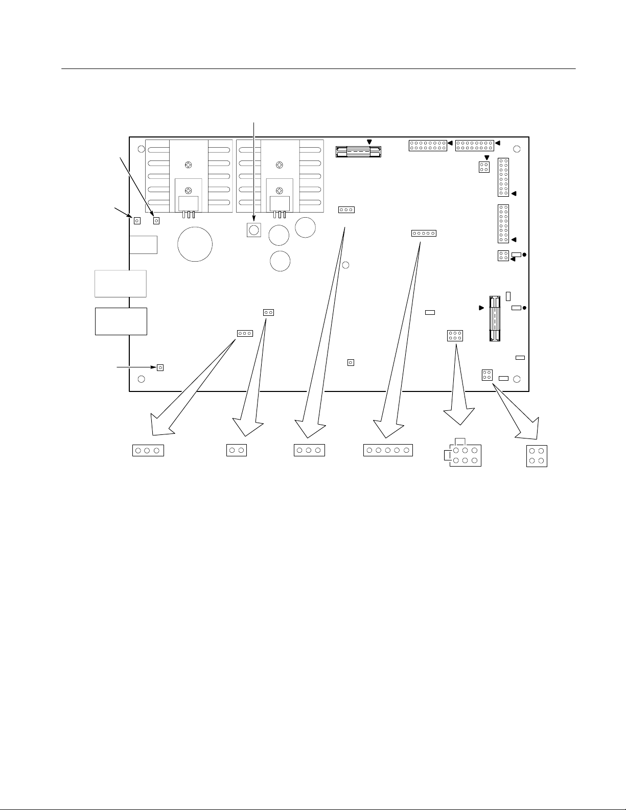
R38 (VDDadjust )
Adjustment/Verification Fixture Adjustment
J10 (VDD)
External
Clock in
J9 ( GND )
J8 (VEE)
J18
Hold/Setup
J26
J17
select
SetupHold
Jumper installed:
clocked on falling edge
Jumper removed:
clocked on rising edge
J19
J17
J19
J15
Ext/Int
Clock select
J14
J15
IntExt
12345
J16
Deskew
J6 J7
J20
J16
C17
GND
J13
Vcc
Deskew
Probe
setup
J13
P6434
Deskew/Probe setup
J1
J2
J3
R321
J5
R39
J4
R127
R85
R67
1
Clock
Clock
GND
GND
J4
Setup/Hold
Clock out
Figure 5- 3: Adjustm ent/verification fixture circuit board layout
TLA600 Series Logic Analyzer Service Manual
5- 11
Page 100

Adjustment/Verification Fixture Adjustment
Internal Clock Frequency
Check
The following procedure checks the internal clock frequency.
Parameter tested I nternal Clock Frequency
Equipment
Required
Prerequisites Warm-up time: 30 minutes for adjustment/verific ation fixture and test
Adjustment/verification fixture and power supply (item 2)
Frequency counter (item 8)
Signal generator (item 16)
Shorting jumpers (item 14)
equipment
1. Set up the frequency counter as follows:
a. Right input (10 Hz -- 100 MHz)
b. Select Direct Resolution: 10 Hz
c. 1 M input termination
d. X1 Attenuation
2. Move one jumper on J16 to DESKEW (pins 2 and 3). Keep the other jumper
connected to pins 4 and 5.
3. Using the frequency counter, measure the oscillator frequency at J1. It will
measure 50.0650 MHz ±0.01% (50.0600 -- 50.0700).
5- 12
TLA600 Series Logic Analyzer Service Manual
 Loading...