


xx
TLA5KUP
ZZZ
Logic Analyzer Field Upgrade Kit
Instructions
This document applies to TLA System Software Version 5.6
Warning
These servicing instructions are for use by qualified personnel
only. To avoid per
unless you are qualified to do so. Refer to all safety summaries
prior to performi
sonal injury, do not perform any servicing
ng service.
www.tektronix.com
077-0835-03

Copyright © Tektronix. All rights reserved. Licensed software products are owned by Tektronix or its subsidiaries
or suppliers, and are protected by national copyright laws and international treaty provisions.
Tektronix products are covered by U.S. and foreign patents, issued and pending. Information in this publication
supersedes that in all previously published material. Specifications and price change privileges reserved.
TEKTRONIX and TEK are registered trademarks of Tektronix, Inc.
Contacting Tektronix
Tektronix, Inc.
14200 SW Karl Braun Drive
P.O . Bo x 50 0
Beaverto
USA
For product information, sales, s ervice, and t echnical support:
n, OR 97077
In North America, call 1-800-833-9200.
World wide , visi t www.tektronix.com to find contacts in your area.

Warranty 6
Tektronix warrants that the parts and modules (“parts”) that it manufactures and sells will be free from defects in
materials and workmanship for a period of three (3) months from the date of shipment. If any such part proves
defective during this warranty period, Tektronix, at its option, either will repair the defective part without charge,
or will provide a replacement in exchange for the defective part. Parts and modules used by Tektronix for
warranty wo
the property of Tektronix.
rk may be new or reconditioned to like new performance. All replaced parts and modules become
In order to o
the warranty period and make suitable arrangements for the performance of service. Customer shall be responsible
for packaging and shipping the defective part to the service center designated by Tektronix, with shipping charges
prepaid. Tektronix shall pay for the return of the part to Customer if the shipment is to a location within the country
in which the Tektronix service center is located. Customer shall be responsible for paying all shipping charges,
duties, taxes, and any other charges for parts returned to any other locations.
This warranty shall not apply to any defect, failure or damage caused by improper use or improper or inadequate
maintenance and care. Tektronix shall not be obligated to furnish service under this warranty a) to repair damage
result
repair damage resulting from improper use or connection to incompatible equipment; c) to repair any damage
or malfunction caused by the use of non-Tektronix supplies; or d) to service a part that has been modified or
integrated with other products or parts when the effect of such modification or integration increases the time or
difficulty of servicing the part.
THIS WARRANTY IS GIVEN BY TEKTRONIX WITH RESPECT TO THE PART IN LIEU OF ANY OTHER
WARRANTIES, EXPRESS OR IMPLIED. TEKTRONIX AND ITS VENDORS DISCLAIM ANY IMPLIED
WARRANTIES OF MERCHANTABILITY OR FITNESS FOR A PARTICULAR PURPOSE. TEKTRONIX’
PONSIBILITY TO REPAIR OR REPLACE DEFECTIVE PARTS IS THE SOLE AND EXCLUSIVE
RES
REMEDY PROVIDED TO THE CUSTOMER FOR BREACH OF THIS WARRANTY. TEKTRONIX AND ITS
VENDORS WILL NOT BE LIABLE FOR ANY INDIRECT, SPECIAL, INCIDENTAL, OR CONSEQUENTIAL
DAMAGES IRRESPECTIVE OF WHETHER TEKTRONIX OR THE VENDOR HAS ADVANCE NOTICE OF
THE POSSIBILITY OF SUCH DAMAGES.
btain service under this warranty, Customer must notify Tektronix of the defect before the expiration of
ing from attempts by personnel other than Tektronix representatives to install, repair or service the part; b) to

Warranty 9(b)
Tektronix warrants that the media on which this software product is furnished and the encoding of the programs on
the media will be free from defects in materials and workmanship for a period of three (3) months from the date of
shipment. If any such medium or encoding proves defective during the warranty period, Tektronix will provide
a replacement in exchange for the defective medium. Except as to the media on which this software product is
furnished,
Tektronix does not warrant that the functions contained in this software product will meet Customer’s requirements
or that the operation of the programs will be uninterrupted or error-free.
In order to obtain service under this warranty, Customer must notify Tektronix of the defect before the expiration
of the warranty period. If Tektronix is unable to provide a replacement that is free from defects in materials and
workmanship within a reasonable time thereafter, Customer may terminate the license for this software product
and return this software product and any associated materials for credit or refund.
THIS WARRANTY IS GIVEN BY TEKTRONIX WITH RESPECT TO THE PRODUCT IN LIEU OF ANY
OTHER WARRANTIES, EXPRESS OR IMPLIED. TEKTRONIX AND ITS VENDORS DISCLAIM ANY
IMPLIED WARRANTIES OF MERCHANTABILITY OR FITNESS FOR A PARTICULAR PURPOSE.
TEKTRO
PAYMENT IS THE SOLE AND EXCLUSIVE REMEDY PROVIDED TO THE CUSTOMER FOR BREACH
OF THIS WARRANTY. TEKTRONIX AND ITS VENDORS WILL NOT BE LIABLE FOR ANY INDIRECT,
SPECIAL, INCIDENTAL, OR CONSEQUENTIAL DAMAGES IRRESPECTIVE OF WHETHER TEKTRONIX
OR THE VENDOR HAS ADVANCE NOTICE OF THE POSSIBILITY OF SUCH DAMAGES.
this software product is provided “as is” without warranty of any kind, either express or implied.
NIX’ RESPONSIBILITY TO REPLACE DEFECTIVE MEDIA O R REFUND CUSTOMER’S

Table of Contents
Service Safety Summary.......... ................................ .................................. ............... v
Preface .............................................................................................................. vi
Products Eligible for TLA5KUP Upgrades........ ................................ ........................ vi
Service and Upgrade Notes .......................... .................................. ..................... viii
Adjustment and Certification Interval ..................................................................... viii
Service Offerings ............................................................................................ viii
TLA5KUP Option 10: Memory Upgrade Installation................. .................................. ....... 1
Instruments ..................................................................................................... 1
Parts List ................... ................................ ................................ ..................... 1
Minimum Tool and Equipment List .. ................................ ................................ ....... 1
Installation Prerequisites ....... .................................. ................................ ............. 1
Remove the Accessories Pouch .............................................................................. 2
Remove the Trim and Covers ................................................................................ 3
Remove the Right-Side Cover................................................................................ 5
Adding Memory ............................ ................................ ................................ ... 6
Verifying Operation................................. .................................. ......................... 7
Attach the Upgrade Kit Label to the Instrument ............................ ............................... 7
TLA5KUP Option 11: Memory Upgrade Installation................................... ....................... 9
Instruments ..................................................................................................... 9
Parts List ................... ................................ ................................ ..................... 9
Minimum Tool and Equipment List .. ................................ ................................ ....... 9
Installation Prerequisites ....... .................................. ................................ ............. 9
Remove the Accessories Pouch ............................................................................. 10
Remove the Trim and Covers ............................................................................... 11
Remove the Right-Side Cover............................................................................... 13
Adding Memory ............................ ................................ ................................ .. 14
Verifying Operation................................. .................................. ........................ 15
Attach the Upgrade Kit Label to the Instrument ............................ .............................. 15
TLA5KUP Option 15: iView External Oscilloscope Cable Installation .. .. . .. . .. .. . .. ... .. . .. .. . .. .. . .. . .. 17
Instruments .................................................................................................... 17
Minimum Tool and Equipment List .. ................................ ................................ ...... 17
Parts List ................... ................................ ................................ .................... 17
Installation Prerequisite ........................ ................................ .............................. 17
Installation Instructions .... ................................ .................................. ................ 17
Attach the Upgrade Kit Label to the Instrument ............................ .............................. 18
TLA5KUP Option 20: CD-RW/DVD-ROM Drive Upgrade................................................. 19
Instruments .................................................................................................... 19
Parts List ................... ................................ ................................ .................... 19
Minimum Tool and Equipment List .. ................................ ................................ ...... 19
TLA5KUP Logic Analyzer Field Upgrade Kit i

Table of Contents
Preparation............................... .................................. ................................ .... 20
Remove the Accessories Pouch ............................................................................. 21
Remove the Trim and Covers ............................................................................... 21
Remove the Right-Side Cover......................... ................................ ...................... 23
Locator Diagram.............................................................................................. 24
Remove the Floppy Disk Drive ............................................................................. 25
Replace the
Verifying Operation................................. .................................. ........................ 26
Attach the Upgrade Kit Label to the Instrument .......................................................... 26
TLA5KUP Option 46: TLA Application Software Upgrade ................................................. 27
Instruments .................................................................................................... 27
Installation Prerequisite ........................ ................................ .............................. 27
Parts Li
Minimum Tool and Equipment List ........................................................................ 27
Upgrade Instruction Overview .............................................................................. 27
Update the Software .......................................................................................... 28
Upgrade the Instrument Firmware.. ................................ ................................ ........ 29
Upgrade the Mainframe BIOS (Instruments with Serial Numbers B020000 to B049999 Only) .. .. 30
Cali
Installing the TLA Application Software on a PC .. .. . .. .. . .. .. . .. . .. .. . .. .. . .. .. . .. . .. .. . .. .. . .. .. . .. . .. 31
Attach the Upgrade Kit Label to the Instrument .......................................................... 33
CD Drive ........................................................................................ 25
st....................................................................................................... 27
brate the Instrument.............................. .................................. ...................... 31
ii TLA5KUP Logic Analyzer Field Upgrade Kit

List of Figures
Figure 1: Trim and covers .............................. .................................. ......................... 4
Figure 2: Right-side cover removal ........................... ................................ ................... 5
Figure 3: Memory module and battery location................................................................. 6
Figure 4: Ki
Figure 5: Trim and covers .............................. .................................. ........................ 12
Figure 6: Right-side cover removal ........................... ................................ .................. 13
Figure 7: Memory module and battery location................................................................ 14
Figure 8: Kit label locations.......... ................................ ................................ ............ 15
Figure 9: Kit label locations.......... ................................ ................................ ............ 18
Figure 1
Figure 11: Right-side cover removal ............................ .................................. .............. 23
Figure 12: Locator diagram .............. ................................ .................................. ...... 24
Figure 13: Kit label locations .. ................................ .................................. ................ 26
Figure 14: Revision and kit label locations..................................................................... 33
t label locations...................................... ................................ ................. 7
0: Trim and covers................. ................................ .................................. .... 22
List
of Tables
Table i: TLA5000B and TLA5000 Series logic analyzers eligible for upgrades........................... vi
le ii: TLA5KUP Logic Analyzer Field Upgrade Matrix................................................. vii
Tab
Table 1: TLA5KUP Option 10 parts list ......................................................................... 1
Table 2: Tools required for installing upgrade . .. . .. .. . .. ... .. . .. .. . .. . .. .. . .. .. . .. ... .. . .. .. . .. . .. .. . .. .. . .. .. . 1
Table 3: TLA5KUP Option 11 parts list ......................................................................... 9
Table 4: Tools required for installing upgrade . .. . .. .. . .. ... .. . .. .. . .. . .. .. . .. .. . .. ... .. . .. .. . .. . .. .. . .. .. . .. .. . 9
Table 5: TLA7KUP Option 15 parts list ........................................................................ 17
Table 6: TLA5KUP Option 20 parts list ........................................................................ 19
Table 7: Tools required for installing upgrade . .. . .. .. . .. ... .. . .. .. . .. . .. .. . .. .. . .. ... .. . .. .. . .. . .. .. . .. .. . .. .. 19
Table 8: TLA5KUP Option 46 parts list ........................................................................ 27
Table 9: TLA5000 BIOS settings.. . .. .. . .. .. . .. .. . .. .. . .. . .. .. . .. .. . .. .. . .. . .. .. . .. .. . .. .. . .. .. . .. .. . .. . .. .. . .. . 31
TLA5KUP Logic Analyzer Field Upgrade Kit iii

Table of Contents
iv TLA5KUP Logic Analyzer Field Upgrade Kit

Service Safety S ummary
Only qualified personnel should perform service procedures. Read this Service
Safety Summary and the General Safety Summary before performing any service
procedures.
Analyzer Family Product Safety & Compliance Instructions (Tektronix part
number 071-2591-xx).
Do Not Service Alone. Do not perform internal service or adjustments of this
product unless another person capable of rendering first aid and resuscitation is
present.
Disconnect Power. To avoid electric shock, switch off the instrument power, then
disconnect the power cord from the mains power.
UseCareWhenServicingWithPowerOn. Dangerousvoltagesorcurrentsmay
exist i
disconnect test leads before removing protective panels, soldering, or replacing
components.
To avoid electric shock, do not touch exposed connections.
The General Safety Summary can be found in the Tektronix Logic
n this product. Disconnect power, remove b attery (if applicable), and
TLA5KUP Logic Analyzer Field Upgrade Kit v

Preface
Preface
This manual c
ontains specific information about the TLA5KUP logic analyzer
field upgrades. The logic analyzer field upgrades consist of software and hardware
options for the TLA5000B and TLA5000 Series logic analyzers.
Products Eligible for TLA5KUP Upgrades
Table i lists all of the TLA5000B and TLA5000 Series l ogic analyzers eligible for
upgrades via the TLA5KUP field upgrade kits. The table tells you if your logic
analyzer is eligible for an upgrade. If it is, choose one of the possible upgrade
paths. (See Table ii.)
Table i:
Configuration Operating system TLA application software
TLA5000
TLA500
TLA5000
1
TLA5000B and TLA5000 Series logic analyzers eligible for upgrades
B
0
TLA Application Software Version 5.6 is not supported on instruments with Windows 2000, nor is an upgrade to
Windows XP available.
Microsoft Windows XP
Professional
Microsoft Windows XP
Professional
soft Windows 2000
Micro
Professional
1
n5.6
Versio
Version 5.1 SP1
n5.6
Versio
Version 5.1 SP1
Version 5.1
on 5.0
Versi
Version 4.4
on 4.3
Versi
The TLA5KUP upgrade kits are designed for "One TLA5KUP upgrade kit
per TLA5000B or TLA5000 mainframe." If you want to upgrade multiple
mainframes, you must order one TLA5KUP upgrade kit with the appropriate
ions for each mainframe.
opt
The latest TLA Application Software has been tested and can be installed and will
supported by Tektronix only on the Tektronix-supplied version of Windows XP.
be
vi TLA5KUP Logic Analyzer Field Upgrade Kit

Preface
Table ii: TLA5K
UP Logic Analyzer Field Upgrade Matrix
New capability desired Current configuration Please order
TLA5000B,TLA SW V5.1 SP1 TLA5KUP Option 46Add New Software Features Add new functionality
to existing logic analyzers by upgrading to the TLA
Application
Software V5.6; requires Windows XP.
Add more DRAM Increase controller memory from
512 MB to 1 GB.
2
TLA5000, TLA SW V5.1 or V 5.0 TLA5KUP Option 46
TLA5000B, TLA SW V5.6 TLA5KUP Option 11
TLA5000B, TLA SW V5.1 SP1 TLA5KUP Options 11 and 46
TLA5000, TLA SW V5.0 or V 5.1 TLA5KUP Options 10 and 46
Add DVD-ROM/CD-RW Drive Add DVD-ROM/CD-RW
Drive to b
ack up or transfer user and data files.
TLA5KUP Option 20 is only needed for TLA5000
instruments with serial numbers B010000 to B029999.
w iView External Oscilloscope Capability
Add Ne
Add capability to view data from Tektronix oscilloscopes
correlated directly on the logic analyzer
res latest TLA Application Software and
Requi
1
.
Windows XP.
TLA5000 mainframe memory requirements: 512 MByte
mmended.
reco
Upgrade Logic Analyzer Record Length Enhance your
rent logic analyzer by increasing state speed or record
cur
length. Run the PowerFlex Utility to inform you what
upgrades are available. Instructions to obtain an upgrade
provided.
are
TLA5000, TLA SW V4.4 or V4.3
with Windows 2000
2
TLA5000B, TLA SW V5.6
TLA5000B, TLA SW V5.1 SP1 TLA5KUP Option 46
TLA5000, TLA SW V5.0 or V 5.1 TLA5KUP Options 20 and 46
TLA5000,TLA SW V4.4 or
2
V4.3
00B, TLA SW V5.6
TLA50
00B, TLA SW V5.1 SP1
TLA50
000, TLA SW V5.0 or V 5.1
TLA5
000, TLA SW V4.4 or
TLA5
2
V4.3
5000B, TLA SW V5.6 or
TLA
V5.1 SP1
TLA5000 series logic
Any
analyzer with TLA SW V5.1 or
below
TLA5KUP Option 10
-
TLA5KUP Option 20
UP Option 15
TLA5K
UP Options 15 and 46
TLA5K
KUP Options 15 and 46
TLA5
KUP Option 15
TLA5
the PowerFlex Utility software
Run
located on the instrument and
then purchase the appropriate
erFlex kit.
Pow
Add Cart: Any TLA5000 mainframe Choice of either K4000 or LACART
Add Rackmount Kit
Any TLA5000 mainframe 016-1790-04 (Same as used
ith TDS6000 and TDS7000
w
instruments)
16-1522-xx
Add Wheeled Transport Case Any TLA5000 mainframe
1
For a list of supported Tektronix oscilloscopes, please visit our Web site at www.tektronix.com/la.
2
TLA Application Software Version 5.6 is not supported on instruments with Windows 2000, nor is an upgrade to Windows XP available.
0
TLA5KUP Logic Analyzer Field Upgrade Kit vii

Preface
Service and Up
grade Notes
To prevent personal injury or damage to the instrument, consider the following
requirements before attempting service:
Read the General Safety Summary and Service Safety Summary found in the
Tektronix Logic Analyzer Family Product Safety & Compliance Instructions
(Tektronix part number 071-2591-xx).
Only qualified service personnel should perform the procedures in this manual.
Be sure to follow all warnings, cautions and notes.
Adjustment and Certification Interval
Generally, you should perform the adjustments an
procedures described in the TLA5000 Logic Analyzer Series Service Manual
(Tektronix part number, 071-1305-xx) once per year, or following repairs that
may affect a djustment or c alibration.
Service Offerings
Tektronix provides service to cover repair under warranty as well as other services
that are designed to meet your specific service needs.
d performance verification
Warranty Repair Service
Calibration a nd Repair
Service
Whether providing warranty repair service or any of the other services listed
below, Tektronix service technicians are equipped to service your logic analyzer.
Services are provided at Tektronix Services Centers.
The warranty for this product is located behind the title page in this manual.
Tektronix technicians provide warranty service at most Tektronix service locations
worldwide. The Tektronix product catalog lists all service locations worldwide, or
you can visit us on our Customer Services World Center Web site at:
Tektronix.com/Measurement/Service
In addition to warranty repair, Tektronix Service offers calibration and other
services which provide solutions to your service needs and quality standards
compliance requirements.
The following services can be tailored to fit your requirements for calibration
and/or repair of your logic analyzer.
Service Options. Tektronix service options can be s elected at the time you
purchase your instrument. You select these options to provide the services that
best meet your service needs.
viii TLA5KUP Logic Analyzer Field Upgrade Kit

Preface
Service Agreem
then service agreements are available on an annual basis to provide calibration
services or post-warranty repair coverage. Service agreements may be customized
to meet special turn-around time and/or on-site requirements.
Service on Demand. Tektronix offers calibration and repair services on a
"per-incid
Self Service. Tektronix supports repair to the replaceable-part level by providing
for circuit board exchange.
Use this service to reduce down-time for repair by exchanging circuit b oards for
remanufactured ones. Tektronix ships updated and tested exchange boards. Each
board comes with a 90-day service warranty.
For More
engineer for more information on any of the Calibration and Repair Services
just described.
ents. If service o ptions are not added to the instrument purchase,
ent" basis that is available with standard prices.
Information. Contact your local Tektronix service center or sales
TLA5KUP Logic Analyzer Field Upgrade Kit ix

Preface
x TLA5KUP Logic Analyzer Field Upgrade Kit

TLA5KUP Option 10: Memory Upgrade Installation
TLA5KUP option 10 provides the capability of upgrading the memory on your
TLA5000 Series logic analyzer to 1 GB.
NOTE. These
upgrade the memory on the TLA5000B Series logic analyzers, please order
TLA5KUP option 11.
instructions only apply to TLA5000 Series logic analyzers. To
Instruments
Instrume
TLA5000 S
nts
eries Logic Analyzers
Parts List
Table 1: TLA5KUP Option 10 parts list
Quantity Part number Description
1 ea 156-9442-xx 512 MB DIMM
1ea
Minimum Tool and Equipment List
Table 2: Tools required for installing upgrade
N/A
Serial nu
All Seria
TLA5KUP kit label
mber range
l Numbers
Item no. Name Description General Tool number
1
2
Screwdriver
handle
T-15 TORX
tip
Accepts TORX-driver bits
Used for removing most the
instrument’s screws. TORX-driver
bit for T-15 size screw heads
620-440
640-247
Installation Prerequisites
These instructions assume that you are familiar with servicing the instrument. If
you need further details for disassembling or reassembling the instrument, refer
to the TLA5000 Logic Analyzer Series Service Manual (071-1305-xx).Youmay
also contact your nearest Tektronix, Inc., Service Center or Tektronix Factory
Service Center for installation assistance.
Be sure to observe the following precautions to avoid damaging the logic analyzer
while preparing to service it.
TLA5KUP Logic Analyzer Field Upgrade Kit 1

TLA5KUP Option 10: Memory Upgrade Installation
CAUTION. Many components within the instrument are susceptible to
static-disch
Service only in a static-free environment. Observe standard handling precautions
for static-sensitive devices.
Always wear a grounded wrist strap, grounded foot strap, and static-resistant
apparel while installing this kit.
Do not handle static-sensitive components on boards.
arge damage.
Remo
Transport
conductive foam. Label any package that contains static-sensitive assemblies.
Do not all
work surface.
Avoid ha
capable of generating a static charge.
WARNIN
in this subsection, disconnect the power cord from the line voltage source. Failure
to do so could cause serious injury or death.
and store static-sensitive boards in their original containers or on
ow anything capable of holding or generating a static charge on the
ndling boards in areas that have a floororworksurfacecoverthatis
G. Dangerous voltages may be present. Before performing any procedure
ve the Accessories Pouch
Remove the accessories pouch to access the covers on the instrument.
1. Turn the logic analyzer off.
2. Remove the power cord and all probes.
3. Open the pouch and locate the two snaps on the inside front side of the pouch.
4. Ge
5. At the rear of the instrument, peel off the Velcro that holds the pouch to the
6. Set the pouch aside.
7. To reinstall the pouch, perform these steps in reverse order. Tighten the T-15
2 TLA5KUP Logic Analyzer Field Upgrade Kit
ntly pull on each of the two tabs to unsnap the front of the pouch.
nstrument.
i
TORX-drive screws to 8-in lbs.

TLA5KUP Option 10: Memory Upgrade Installation
Remove the Tri
mandCovers
Remove the trim and covers. (See Figure 1 on page 4.)
1. Remove the top cover trim.
a. Remove the two T-15 TORX-drive screws that secure the top cover trim
b. Remove the snap studs from the top cover.
c. Slide the trim panel toward the rear of the instrument allowing the tabs
2. Remove the right side trim.
NOTE. When you remove the CD Drive trim, notice the notches in the trim that
provide the clearance for the chassis screws located under the trim. When you
e the trim, make sure that you orient the trim with the notches in the correct
replac
location. Otherwise the trim may not fit properly.
a. Remov
to the instrument.
to clear the cover openings, then pull out to remove the panel from the
instrument (you may need to loosen the two top black feet on the back of
the instrument if the cover does not come off easily).
e the Drive trim by inserting a flat blade s crewdriver in the bottom
slot of the trim and gently prying the trim piece out of the side panel. Pull
the trim up and out from the instrument.
b. Remove the two T-15 TORX-drive screws that secure the right side trim
to the bottom of the instrument.
c. Slide the trim panel toward the rear of the instrument allowing the tabs to
clear the cover openings, then pull the panel from the instrument.
TLA5KUP Logic Analyzer Field Upgrade Kit 3

TLA5KUP Option 10: Memory Upgrade Installation
Figure 1 : Trim and covers
4 TLA5KUP Logic Analyzer Field Upgrade Kit

TLA5KUP Option 10: Memory Upgrade Installation
Remove the Rig
ht-Side Cover
Remove the right-side cover to access most of the internal components of the
instrument. (See Figure 2.)
NOTE. All mo
mounting hole.
1. Remove the
and right sides of the chassis.
2. Remove th
CAUTION. The covers can damage internal cables if they get tangled during
removal or installation. Take care not to bind or snag the covers on the cables as
you remove or install.
unting screw holes are indicated by a star etched around the
15 T-15 TORX-drive screws that secure the cover to the top
ecover.
gure 2: Right-side cover removal
Fi
TLA5KUP Logic Analyzer Field Upgrade Kit 5

TLA5KUP Option 10: Memory Upgrade Installation
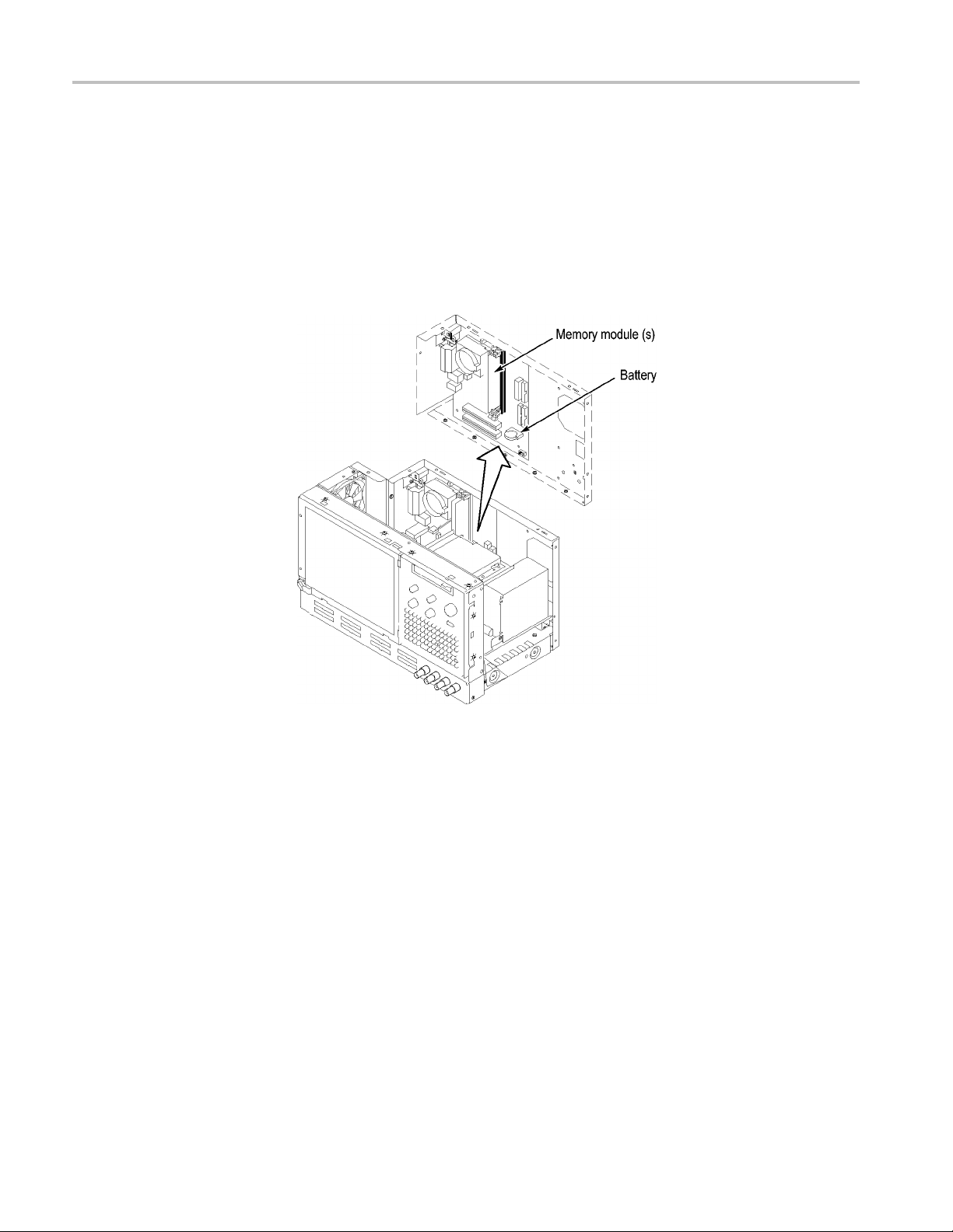
Adding Memory
The memory sockets are located on the processor board mounted to the back
panel. (See Figure 3.)
1. Install the memory module as f ollows:
a. For TLA5000 instruments with serial numbers B010000 to B019999,
install the memory module in the single, spare socket.
b. For TLA5000 instruments w ith serial numbers B020000 or higher,
install the memory module in one of the spare sockets. For optimum
performance, leave one socket empty between the original and new
DIMMs (the correct socket for the new memory m odule is labeled
Channel B DIMM 0).
Figure 3: Memory module a nd battery location
2. Reinstall the trim, covers, and the accessories pouch.
6 TLA5KUP Logic Analyzer Field Upgrade Kit

TLA5KUP Option 10: Memory Upgrade Installation
Verifying Ope
ration
To verify the proper operation of the logic analyzer, follow these steps:
1. Plug the power cord in and turn the logic analyzer on.
2. Verify that the instrument passes all power-up diagnostics.
3. Exit all applications and close any open windows.
4. Click Star
5. Select Programs from the Start menu.
6. Select the CheckIt Utilities application from the Programs menu.
7. Run the appropriate verification tests from the application.
8. Turn the logic analyzer off, and then on again before running any application
software including the TLA application software.
t in the Windows tool bar.
Attach the Upgrade Kit Label to the Instrument
After completing all the previous steps, you need to install the upgrade kit label
on the instrument to indicate that the kit is installed.
Locate the big label on the rear of the instrument, and then attach the TLA5KUP
kit label. (See Figure 4.)
Figure 4: Kit label locations
TLA5KUP Logic Analyzer Field Upgrade Kit 7

TLA5KUP Option 10: Memory Upgrade Installation
8 TLA5KUP Logic Analyzer Field Upgrade Kit

TLA5KUP Option 11: Memory Upgrade Installation
TLA5KUP option 11 provides the capability of upgrading the memory on your
TLA5000B Series logic analyzer to 1 GB.
NOTE. These
upgrade the memory on the TLA5000 Series logic analyzers, please order
TLA5KUP option 10.
instructions only apply to TLA5000B Series logic analyzers. To
Instruments
Instrume
TLA5000B
nts
Series Logic Analyzers
Parts List
Table 3: TLA5KUP Option 11 parts list
Quantity Part number Description
1 ea 167-0428-xx 512 MB DIMM
1ea
Minimum Tool and Equipment List
Table 4: Tools required for installing upgrade
N/A
Serial nu
All Seria
TLA5KUP kit label
mber range
l Numbers
Item no. Name Description General Tool number
1
2
Screwdriver
handle
T-15 TORX
tip
Accepts TORX-driver bits
Used for removing most the
instrument’s screws. TORX-driver
bit for T-15 size screw heads
620-440
640-247
Installation Prerequisites
These instructions assume that you are familiar with servicing the instrument. If
you need further details for disassembling or reassembling the instrument, refer
to the TLA5000 Logic Analyzer Series Service Manual (071-1305-xx).Youmay
also contact your nearest Tektronix, Inc., Service Center or Tektronix Factory
Service Center for installation assistance.
Be sure to observe the following precautions to avoid damaging the logic analyzer
while preparing to service it.
TLA5KUP Logic Analyzer Field Upgrade Kit 9

TLA5KUP Option 11: Memory Upgrade Installation
CAUTION. Many components within the instrument are susceptible to
static-disch
Service only in a static-free environment. Observe standard handling precautions
for static-sensitive devices.
Always wear a grounded wrist strap, grounded foot strap, and static-resistant
apparel while installing this kit.
Do not handle static-sensitive components on boards.
arge damage.
Remo
Transport
conductive foam. Label any package that contains static-sensitive assemblies.
Do not all
work surface.
Avoid ha
capable of generating a static charge.
WARNIN
in this subsection, disconnect the power cord from the line voltage source. Failure
to do so could cause serious injury or death.
and store static-sensitive boards in their original containers or on
ow anything capable of holding or generating a static charge on the
ndling boards in areas that have a floororworksurfacecoverthatis
G. Dangerous voltages may be present. Before performing any procedure
ve the Accessories Pouch
Remove the accessories pouch to access the covers on the instrument.
1. Turn the logic analyzer off.
2. Remove the power cord and all probes.
3. Open the pouch and locate the two snaps on the inside front side of the pouch.
4. Ge
5. At the rear of the instrument, peel off the Velcro that holds the pouch to the
6. Set the pouch aside.
7. To reinstall the pouch, perform these steps in reverse order. Tighten the T-15
10 TLA5KUP Logic Analyzer Field Upgrade Kit
ntly pull on each of the two tabs to unsnap the front of the pouch.
nstrument.
i
TORX-drive screws to 8-in lbs.

TLA5KUP Option 11: Memory Upgrade Installation
Remove the Tri
mandCovers
Remove the trim and covers. (See Figure 5 on page 12.)
1. Remove the top cover trim.
a. Remove the two T-15 TORX-drive screws that secure the top cover trim
b. Remove the snap studs from the top cover.
c. Slide the trim panel toward the rear of the instrument allowing the tabs
2. Remove the right side trim.
NOTE. When you remove the CD Drive trim, notice the notches in the trim that
provide the clearance for the chassis screws located under the trim. When you
e the trim, make sure that you orient the trim with the notches in the correct
replac
location. Otherwise the trim may not fit properly.
a. Remov
to the instrument.
to clear the cover openings, then pull out to remove the panel from the
instrument (you may need to loosen the two top black feet on the back of
the instrument if the cover does not come off easily).
e the Drive trim by inserting a flat blade s crewdriver in the bottom
slot of the trim and gently prying the trim piece out of the side panel. Pull
the trim up and out from the instrument.
b. Remove the two T-15 TORX-drive screws that secure the right side trim
to the bottom of the instrument.
c. Slide the trim panel toward the rear of the instrument allowing the tabs to
clear the cover openings, then pull the panel from the instrument.
TLA5KUP Logic Analyzer Field Upgrade Kit 11

TLA5KUP Option 11: Memory Upgrade Installation
Figure 5 : Trim and covers
12 TLA5KUP Logic Analyzer Field Upgrade Kit

TLA5KUP Option 11: Memory Upgrade Installation
Remove the Rig
ht-Side Cover
Remove the right-side cover to access most of the internal components of the
instrument. (See Figure 6.)
NOTE. All mo
mounting hole.
1. Remove the
and right sides of the chassis.
2. Remove th
CAUTION. Take care not to bind or snag the covers on the internal cabling as
you remove or install.
unting screw holes are indicated by a star etched around the
15 T-15 TORX-drive screws that secure the cover to the top
ecover.
Figure 6: Right-side cover removal
TLA5KUP Logic Analyzer Field Upgrade Kit 13
TLA5KUP Option 11: Memory Upgrade Installation
Adding Memory
The memory sockets are located on the processor board mounted to the back
panel. (See Figure 7.)
1. Install the memory module in one of the spare sockets. For optimum
performance, leave one socket empty between the original and new DIMMs
(the correct socket for the new memory module is labeled Channel B
DIMM 0).
Figure 7: Memory module a nd battery location
2. Reinstall the trim, covers, and the accessories pouch.
14 TLA5KUP Logic Analyzer Field Upgrade Kit

TLA5KUP Option 11: Memory Upgrade Installation
Verifying Ope
ration
To verify the proper operation of the logic analyzer, follow these steps:
1. Plug the power cord in and turn the logic analyzer on.
2. Verify that the instrument passes all power-up diagnostics.
3. Exit all applications and close any open windows.
4. Click Star
5. Select Programs from the Start menu.
6. Select the CheckIt Utilities application from the Programs menu.
7. Run the appropriate verification tests from the application.
8. Turn the logic analyzer off, and then on again before running any application
software including the TLA application software.
t in the Windows tool bar.
Attach the Upgrade Kit Label to the Instrument
After completing all the previous steps, you need to install the upgrade kit label
on the instrument to indicate that the kit is installed.
Locate the big label on the rear of the instrument, and then attach the TLA5KUP
kit label. (See Figure 8.)
Figure 8: Kit label locations
TLA5KUP Logic Analyzer Field Upgrade Kit 15

TLA5KUP Option 11: Memory Upgrade Installation
16 TLA5KUP Logic Analyzer Field Upgrade Kit

TLA5KUP Option 15: iView External Oscilloscope Cable
Installation
TLA5KUP option 15 provides the capability of connecting your logic analyzer to
an external Tektronix oscilloscope through the iView cable.
Instruments
Instrument
TLA5000 Se
TLA5000B
s
ries Logic Analyzers
Series Logic Analyzers
Minimum Tool and Equipment List
No special tools or equipment are required.
Parts List
Table 5: TLA7KUP Option 15 parts list
Quantity Part number Description
1 ea 012-1614-xx iView external oscilloscope
1ea
Installation Prerequisite
N/A
Serial numb
All Serial
All Seria
Numbers
l Numbers
er range
cable kit
TLA5KUP kit label
hough iView will operate on TLA Instruments with Windows 2000, Tektronix
Alt
recommends the latest TLA Application Software with Windows XP, and 512 MB
minimum mainframe memory. Also requires the latest version of the NI-488.2
software available on the TLA Application software CD; refer to the release notes
on the CD for software version history.
nstallation Instructions
I
Online installation instructions are provided within the TLA application through a
wizard. After powering on the instrument, select Add iView External Scope from
the System menu and follow the online instructions.
TLA5KUP Logic Analyzer Field Upgrade Kit 17

TLA5KUP Option 15: iView External Oscilloscope Cable Installation
Attach the Upgrade Kit Label to the Instrument
After completing the previous steps, you need to install the upgrade kit label on
the instrument to indicate that the kit is installed.
Locate the big label on the rear of the instrument, and then attach the TLA5KUP
kit label. (See Figure 9.)
Figure 9 : Kit label locations
18 TLA5KUP Logic Analyzer Field Upgrade Kit

TLA5KUP Option 20: CD-RW/DVD-ROM Drive Upgrade
TLA5KUP Option 20 replaces the CD-RW drive with a CD-RW/DVD-ROM
drive for your TLA5000 Series logic analyzer. This option does not include any
software med
software to support your new drive.
NOTE. TLA Application Software Version 5.6 is not supported on instruments
with Windows 2000.
Instruments
Instruments Serial number range
TLA5000 Series Logic Analyzers
Parts List
Table 6: TLA5KUP Option 20 parts list
Quantity Part number Description
1 ea 119-7196-xx
1ea
ia and license. Please order TLA5KUP Option 46 to get the latest
B010000 to B029999
CD-RW/DVD-ROM disk drive
N/A
TLA5KUP kit label
Minimum Tool and Equipment List
Table 7: Tools required for installing upgrade
Item no. Name Description General Tool number
1
2
3
Screwdriver
handle
T-15 TORX
tip
#1 Phillips
screwdriver
Accepts TORX-driver bits
Used for removing most the
instrument’s screws. TORX-driver
bit for T-15 size screw heads
Screwdriver for removing Phillips
screws, CD-ROM Drive.
620-440
640-247
Standard tool
TLA5KUP Logic Analyzer Field Upgrade Kit 19

TLA5KUP Option 20: CD-RW/DVD-ROM Drive Upgrade
Preparation
Be sure to observe the following precautions to avoid damaging the logic analyzer
while preparing to service it. Contact your nearest Tektronix, Inc., Service Center
or Tektronix Factory Service Center for installation assistance.
CAUTION. Many components within the instrument are susceptible to
static-dis
Service only in a static-free environment. Observe standard handling precautions
for static-sensitive devices.
Always wear a grounded wrist strap, grounded foot strap, and static-resistant
apparel while installing this kit.
Do not handle static-sensitive components on boards.
charge damage.
Transpo
conductive foam. Label any package that contains static-sensitive assemblies.
Do not a
work surface.
Avoid h
capable of generating a static charge.
WARN
in this subsection, disconnect the power cord from the line voltage source. Failure
to do so could cause serious injury or death.
rt and store static-sensitive boards in their original containers or on
llow anything capable of holding or generating a static charge on the
andling boards in areas that have a floororworksurfacecoverthatis
ING. Dangerous voltages may be present. Before performing any procedure
20 TLA5KUP Logic Analyzer Field Upgrade Kit

Remove the Accessories Pouch
Remove the accessories pouch to access the covers on the instrument.
1. Turn the logic analyzer off.
TLA5KUP Option 20: CD-RW/DVD-ROM Drive Upgrade
2. Remove the po
3. Open the pouch and locate the two snaps on the inside front side of the pouch.
4. Gently pull on each of the two tabs to unsnap the front of the pouch.
5. At the rear of the instrument, peel off the Velcro that holds the pouch to the
instrument.
6. Set the pouch aside.
7. To reinstall the pouch, perform these steps in reverse order. Tighten the T-15
TORX-drive screws to 8-in lbs.
Remove the Trim and Covers
Remove the trim and covers by following this procedure. (See Figure 10 on
page 22.)
1. Remove the top cover trim.
a. Remove the two T-15 TORX-drive screws that secure the top cover trim
b. Remove the snap studs from the top cover.
wer cord and all probes.
to the instrument.
c. Slide the trim panel toward the rear of the instrument allowing the tabs
to clear the cover openings, then pull out to remove the panel from the
instrument (you may need to loosen the two top black feet on the back of
the instrument if the cover does not come off easily).
2. Remove the right side trim.
NOTE. When you remove the CD Drive trim, notice the notches in the trim that
provide the clearance for the chassis screws located under the trim. When you
replace the trim, make sure that y ou orient the trim with the notches in the correct
location. Otherwise the trim may not fit properly.
a. Remove the Drive trim by inserting a flat blade screwdriver in the bottom
slot of the trim and gently prying the trim piece out of the side panel. Pull
the trim up and out from the instrument.
b. Remove the two T-15 TORX-drive screws that secure the right side trim
to the bottom of the instrument.
TLA5KUP Logic Analyzer Field Upgrade Kit 21

TLA5KUP Option 20: CD-RW/DVD-ROM Drive Upgrade
c. Slide the trim p
clear the cover openings, then pull the panel from the instrument.
anel toward the rear of the instrument allowing the tabs to
Figure 10: Trim and covers
22 TLA5KUP Logic Analyzer Field Upgrade Kit

TLA5KUP Option 20: CD-RW/DVD-ROM Drive Upgrade
Remove the Rig
ht-Side Cover
Remove the right-side cover to access most of the internal components of the
instrument. (See Figure 11.)
1. Remove the top and right trim to access the right-side cover.
NOTE. All mounting screw holes are indicated by a star etched around the
mounting h
2. Remove the 15 T-15 TORX-drive screws that secure the cover to the top
and right
3. Remove the cover.
CAUTION
removal or installation. Take care not to bind or snag the covers on the cables as
you remove or install.
ole.
sides of the chassis.
. The covers can damage internal cables if they get tangled during
Figure 11: Right-side cover removal
TLA5KUP Logic Analyzer Field Upgrade Kit 23

TLA5KUP Option 20: CD-RW/DVD-ROM Drive Upgrade
Locator Diagram
Locate the components for the remaining removal and installation procedures.
(See Figure 12.)
Figure 12: Locator diagram
24 TLA5KUP Logic Analyzer Field Upgrade Kit

Remove the Floppy Disk Drive
Remove the floppy disk drive for better access to the CD-RW drive.
1. Locate the Floppy Disk Drive. (See Figure 12.)
TLA5KUP Option 20: CD-RW/DVD-ROM Drive Upgrade
Replace the CD Drive
2. Set the instr
panel is facing you.
3. Remove the c
4. Remove the two T-15 TORX-drive screws that secure the floppy disk drive
assembly t
1. Locate th
2. Remove the single T-15 TORX-drive screw that secures the CD drive
assembl
3. Pull the assembly away from the chassis so that you can disconnect the ribbon
and pow
4. Disconnect the ribbon and power cables and then remove the CD drive from
the ch
5. Remove the Phillips screws that secure the CD drive to the bracket.
6. Gently pull the CD drive away from the connector and remove the drive from
the bracket.
ument so its bottom is down on the work surface and the front
able from the back of the fl oppy disk drive.
o the chassis.
e CD drive in the locator diagram. (See Figure 12 on page 24.)
y to the chassis.
er cables.
assis.
7. Remove the Phillips screws that secure the CD drive adapter board to the
back of the CD drive.
8. Remove the CD drive adapter board from the old CD drive and attach the
board to the new DVD-ROM/CD-RW drive. Install the Phillips screws that
u removed earlier and tighten them to 2 in-lbs.
yo
9. Slide the new drive into the bracket and install the Phillips screws that you
emoved earlier; tighten the screws to 2 in-lbs.
r
10. Install the assembly in the chassis by aligning the two tabs from the bracket to
the slots in the chassis before tightening the TORX-drive screw. Tighten the
T-15 TORX-drive screw to 8 in-lbs.
11. Connect the ribbon and power cables to the assembly.
12. Reinstall the floppy disk drive, right-side cover, trim, and the accessories
pouch.
TLA5KUP Logic Analyzer Field Upgrade Kit 25

TLA5KUP Option 20: CD-RW/DVD-ROM Drive Upgrade
Verifying Ope
ration
To verify the proper operation of the logic analyzer, follow these steps:
1. Attach the power cord and power on the logic analyzer.
2. Exit all applications and c lose any open windows.
3. Click Start in the Windows tool bar.
4. Select Pro
5. Select the CheckIt application from the Programs menu.
6. Run the appropriate verification tests from the CheckIt diagnostics.
7. Insert a CD and verify the CD write capability using the appropriate
media-burning software.
8. Insert a pre-recorded DVD and verify the read capability.
9. Turn the logic analyzer off, and then on again before running any application
software including the TLA application software.
grams from the Start menu.
Attach the Upgrade Kit Label to the Instrument
After completing all the previous steps, you need to install the upgrade kit label
on the instrument to indicate that the kit is installed.
Locate the big label on the rear of the instrument, and then attach the TLA5KUP
kit label. (See Figure 13.)
NOTE. If there is an upgrade kit label already installed, install the new label
oveorbelowtheoldone,whereverthereisroom.
ab
Figure 13: Kit label locations
26 TLA5KUP Logic Analyzer Field Upgrade Kit

TLA5KUP Option 46: TLA Application Software Upgrade
TLA5KUP Option 46 supports the upgrade to TLA application software version
5.6. This kit provides instructions to upgrade the TLA application s oftware
and firmware f
Application Software V5.0 or higher and Windows XP purchased from Tektronix.
The software will also run on a PC with Windows XP.
Instruments
Instruments Serial number range
TLA5000 Series Logic Analyzers All Serial Numbers
TLA5000B Series Logic Analyzers All Serial Numbers
Installation Prerequisite
Requires TLA Application Software Version 5.0 (or higher), Windows XP.
Parts List
or a TLA5000B or TLA5000 Series logic analyzer with TLA
Table 8: TLA5KUP Option 46 parts list
Quantity Part number Description
1ea
1ea
1 sheet
1ea
Minimum Tool and Equipment List
No special tools or equipment are required to install this option.
Upgrade Instruction Overview
NOTE. Third-party software applications are included to use with your logic
analyzer. These applications may include software license agreements. Be sure
to abide by those license agreements.
N/A Tektronix Logic Analyzer Family Application Software
Version 5.6
N/A Nero Software CD
N/A Software revision labels
N/A
TLA5KUP kit label
TLA5KUP Logic Analyzer Field Upgrade Kit 27

TLA5KUP Option 46: TLA Application Software Upgrade
While performi
Throughout this procedure you will see the term "log on as Administrator."
The instrument is set up to automatically log on as Administrator (with no
password) so you may not see the log on prompt. If the network setups have
been changed on your instrument, make sure that you log on as Administrator
or as a user who has administrator privileges. Failure to do so can prevent the
software upgrade from completing successfully.
After logging on as administrator, quit any applications.
If your instrument does not display the file extensions, you need to change
your folder options to display the file extensions. (From the Control Panel,
double-click Folder Options, select the View tab, and then deselect the "Hide
file extensions for known file types" selection.)
Use the Microsoft Windows Add or Remove Programs Control Panel utility
to remove existing software.
You may be asked to restart the instrument after you install each software
package. If you do not restart the instrument when prompted, your software
may not install properly and can cause unpredictable behavior.
If the instrument does not restart normally, press and hold the On/Standby
button for five or six seconds to force a shutdown.
ng the upgrade procedures, keep the following items in mind:
Update the Software
TLA Application Software
NOTE. You may want to compare the software version listed under Software
Compatibility in the release notes against the software on your instrument. If the
software versions do not match, remove the old software using the Microsoft
Windows Add or Remove Programs utility and then install the new software from
the TLA Application CD.
The TLA Application software uses a wizard to remove older software and install
the new software for your instrument.
1. Log on as Administrator.
2. Insert the first CD of the TLA Application software in the instrument.
3. Start Windows Explorer, and browse to and execute D:\TLA Application
SW\Setup.exe.
4. Click Yes to start the installation.
5. Follow any on-screen instructions. If you are asked for permission to
overwrite any read-only files, select Yes to All.
6. After the software has been successfully installed, restart your instrument.
28 TLA5KUP Logic Analyzer Field Upgrade Kit

TLA5KUP Option 46: TLA Application Software Upgrade
Other Software
Complete the fo
Application Software CD:
1. Log on as Admin
2. Insert the TLA Application software CD in the instrument.
3. Start Windows Explorer, and browse the CD to look for your software (you
might need to browse the second CD if you can’t find the software that you
are looking
4. Double-click the executable file for the software and follow the on-screen
instructi
NOTE. When you reinstall the CheckIt Utilities software, you will be prompted
for a serial number; use U7-999999.
Follow the instructions to install the NI-GPIB software to use with iView. (See
page 32, Install the NI-GPIB Software.)
5. After the software has been successfully installed, restart your instrument.
llowing instructions to install other software from the TLA
istrator.
for).
ons.
Upgrade the Instrument Firmware
Complete the following steps if the TLA startup messages indicate that you need
to upgrade the instrument firmware:
1. Log on as Administrator.
2. Exi
3. Click Start → All Programs → Tektronix Logic Analyzer → TLA Firmware
4. Select your instrument from the Firmware Loader - Connection dialog box
5. Select the module from the Supported list box near the top of the window.
6. Select Load Firmware from the Execute menu.
7. Click the TLA520x.lod file.
8. Click Open. You will be asked to confirm your action; click Yes .
9. When the process is complete, exit the firmware loader program.
t the logic analyzer application.
ader.
Lo
nd click Connect.
a
TLA5KUP Logic Analyzer Field Upgrade Kit 29

TLA5KUP Option 46: TLA Application Software Upgrade
Upgrade the Ma
B049999 Only)
inframe BIOS (Instruments with Serial Numbers B020000 to
Use the following steps to determine if you need to upgrade the BIOS on the
logic analyzer mainframe:
1. Restart the logic analyzer and then press function key F2 repeatedly to enter
the BIOS setup.
2. For TLA5000 instruments with serial numbers from B020000 to B039999,
check that the version string ends in P24 or higher. For TLA5000B
instruments with serial numbers from B040000 to B049999, check that the
third field of the BIOS version string is 4089 or highter.
3. If you have the correct version, skip the remaining steps in this procedure.
Restart the instrument, or press the Escape key, and answer OK to discard
any changes and exit (this allows the instrument to restart).
4. To update the BIOS, complete the following steps:
a. Connect to the internet and go
For instruments with serial numbers B020000 to B039999, go to
http://developer.intel.com/design/motherbd/lc/lc_bios.htm.
For instruments with serial numbers B040000 to B049999, go to
http//www.intel.com/products/motherboard/d945gtp/tools.htm.
to one of the following Web sites:
b. Review the information on the Web site about the Express BIOS update
and then download the file and copy it to your instrument desktop.
c. Close all applications on your instrument and then execute the file that
you just downloaded.
NOTE. Do not power down the instrument until the upgrade is complete.
d. Follow the on-screen instructions.
The logic analyzer will update the BIOS and the screen will be blank.
During the update processes you will hear
instrument will restart. A message will appear on the screen when the
upgrade is complete.
The upgrade process should not change the BIOS settings of your
instrument. If the screen remains blank, the video BIOS settings might
have been reset. Complete the following steps to recover from any
problems:
5. Connect an external monitor to the video port near the RS-232 port.
6. Restart the instrument and then press function key F2 to enter the BIOS setup.
several beeps and then the
30 TLA5KUP Logic Analyzer Field Upgrade Kit

TLA5KUP Option 46: TLA Application Software Upgrade
Calibrate the Instrument
The BIOS screen
should appear on the external monitor.
7. Use the keyboard or front panel keys to change the BIOS settings.
Table 9: TLA5000 BIOS settings
Menu Recommended settings
Advanced
Boot
Peripheral
Configuration
Diskette
Configuration
Video
Configuration
Parallel Port Mode
Audio
Diskette Controller
Primary Video
Adapter
Silent Boot
ECP
Disabled
Disabled
PCI
Enabled
8. Press function key F10 to save and exit the BIOS setup. The instrument
should restart and the screen should work properly.
After verifying proper operation, you need to calibrate the logic analyzer.
1. Allow the instrument to warm up for at least 30 minutes before continuing.
2. In the System window, select Calibration and Diagnostics from the System
menu.
3. Click the Self Calibration tab.
4. Select the Run button and click Yes to any confirmation messages.
NOTE. The calibration process may take several minutes.
The Status column indicates Running while the instrument is being calibrated.
5. Verify that the Status column changes to Calibrated.
6. Close the dialog box.
Installing the TLA Application Software on a PC
You can install the TLA application software on a PC for the following purposes:
To run the TLA application software in the Offline mode.
To control a logic analyzer with the same TLA application software version
over a network.
TLA5KUP Logic Analyzer Field Upgrade Kit 31

TLA5KUP Option 46: TLA Application Software Upgrade
Install Third-Party Software
To use all of the
install additional third-party software. The following third-party software is
available on the TLA Application Software CD V5.6:
The NI-GPIB software allows you to use the iView software with your PC.
The SnagIt s
for use with other applications.
NOTE. Several third-party software applications are included to use with your
logic analyzer. These applications may include software license agreements. Be
sure to abide by those license agreements.
Install the NI-GPIB Software. Complete the following steps to install the third-party
software on your PC:
1. Insert the TLA Application Software CD in the CD drive.
2. Browse to the NI-GPIB-USB folder on the CD and run the Setup.exe program.
3. Follow the on-screen instructions and note the items below:
a. When p
features of the TLA application software on your PC, you must
oftware is useful for copying screen shots of logic analyzer data
rompted, select the Typical installation option.
Install the TLA Application
Software
b. When the Add GPIB wizard appears, click Cancel.
c. After restarting the instrument, the NI-488.2 Getting Started wizard
displays. This is not needed; select Do not show at Windows startup
then click X to exit.
and
d. When you first connect the iView cable, the instrument will detect the new
dware. Select Install the software automatically (Recommended).
har
Install the SnagIt Software. Complete the following steps to install the SnagIt
software on your PC:
1. Browse to the SnagIt folder on the CD and run the Setup.exe program.
2. Follow the on-screen instructions.
Browse to the TLA Application software folder on the CD and run the Setup.exe
program. Follow the on-screen instructions to install the TLA application
software.
Ifyouhaveanolderversionofthesoftware on the hard disk, the installation
program will detect it and ask if you want to remove it. Follow the on-screen
instructions to remove the software, answering "Yes" to any prompts. Restart the
instrument when prompted and run the Setup.exe program again.
32 TLA5KUP Logic Analyzer Field Upgrade Kit

TLA5KUP Option 46: TLA Application Software Upgrade
Start the TLA Application
If you have inst
start the software by double-clicking on the TLA Application icon. The TLA
Connection dialog box displays.
1. Select an instrument in the TLA Connection dialog box and then click
Connect. If your instrument is connected to a network, you can connect to
any unused instrument on your local network.
2. Click Offline to start an offline version of the TLA application software.
The TLA Offline software allows you to run the TLA application without
connectingtoaninstrument.Youcananalyzepreviouslyacquireddatafroma
logic analyzer, create or modify reference memories, or perform system tests
without b
alled the TLA application software on a PC for remote operation,
eing connected to an instrument.
Attach the Upgrade Kit Label to the Instrument
After co
instrument to indicate that the kit is installed.
Locate
revision label and the TLA5KUP kit label. (See Figure 14.)
mpleting all the previous steps, install the upgrade kit label on the
the big label on the rear of the instrument, and then attach the software
ure 14: Revision and kit label locations
Fig
TLA5KUP Logic Analyzer Field Upgrade Kit 33
 Loading...