

Page 1

xx
TekExpress® USB 3.0 (USB-RMT)
ZZZ
Automated Receiver Compliance and Margin Test Solutions
Printable Online Help
*P077045803*
077-0458-03
Page 2

Page 3

TekExpress® USB 3.0 (USB-RMT)
Automated Receiver Compliance and Margin Test Solutions
ZZZ
PrintableOnlineHelp
www.tektronix.com
077-0458-03
Page 4

Copyright © Tektronix. All rights reserved. Licensed software products are owned by Tektronix or its
subsidiaries or suppliers, and are protected by national copyright laws and international treaty provisions.
Tektronix products are covered by U.S. and foreign patents, issued and pending. Information in this
publication supersedes that in all previously published material. Specifications and price change privileges
reserved.
TEKTRONIX and TEK are registered trademarks of Tektronix, Inc.
TekExpress is a registered trademark of Tektronix, Inc.
Copyright and Intellectual Property (IP) rights pertain to certain software and hardware products provided
by Ellisys SA, Geneva, Switzerland, in support of the equipment referenced herein. These rights are
maintained by Ellisys, protected under civil laws of the United States, Switzerland, and other countries.
Unauthor
Copyright and Intellectual Property (IP) rights pertain to certain software products provided by Ellisys
SA, Geneva, Switzerland, in support of the equipment referenced herein. These rights are maintained by
Ellisys, protected under civil laws of the United States, Switzerland, and other countries. Unauthorized
reproduction, duplication, or reverse engineering of legally protected materials is forbidden.
ized reproduction, duplication, or reverse engineering of legally protected materials is forbidden.
TekExpress Online help, 076-0219-0
3.
Contacting Tektronix
onix, Inc.
Tektr
14150 SW Karl Braun Drive
P.O . B ox 5 0 0
Beaverton, OR 97077
USA
product information, sales, service, and technical support:
For
In North America, call 1-800-833-9200.
Worldwide, visit www.tektronix.com to find contacts in your area.
Page 5

Table of Contents
General safety summary .......... .................................... .................................... ........ iii
Introduction
Using Online Help............. .................................... .................................... ............. 1
Related documentation............................................................................................. 1
Conventions ................................ .................................... .................................... . 2
Technical support ................................................................................................... 3
Getting started
What is new in this release ........................................................................................ 5
Accessories................................... .................................... ................................... 6
Minimum system requirements ................................................................................... 7
Windows 7 user account settings .................. .................................... ........................... 8
Application directories and content........................................ .................................... ... 9
File name extensions ...... .................................... .................................... ................ 11
How to activate the license ....................................................................................... 12
Before you click Run.................... .................................... .................................... .. 14
Table of Contents
Operating basics
TekExpress application overview................................................................................ 17
Starting the application ... .................................... .................................... ................ 17
Resizing the application window ........................ .................................... .................... 19
Exiting the application .. . .. . .. . .. . .. . .. . .. . .. . .. . .. . .. ... . .. ... . .. ... ... ... ... ... ... ... ... ... ... ... ... .. . ... .. . ... 19
Global controls..................................................................................................... 19
Menus
File menu .................... .................................... .................................... .......... 20
View menu..................................................................................................... 21
Tools menu .................................................................................................... 21
Help menu ..................................................................................................... 23
How to
Select the test(s) ................................................................................................... 25
Configure and run the test(s) ..................................................................................... 26
Calibration (Auto Cal) ............ .................................... .................................... ........ 30
View and Select Connected Instruments .......................... .................................... .......... 31
View the Progress of Analysis ... .................................... .................................... ........ 33
View the Report.................................................................................................... 34
View Test Related Files ..................... .................................... .................................. 35
TekExpress USB 3.0 Automated Solutions Printable Online Help i
Page 6

Table of Contents
Application Examples
USB-RMT Equipment Setup: Device........................................................................... 37
Testing a Device Using Normative Test Approach ............................................................ 38
Testing a Device Using Informative Test Approach ........................................................... 41
TekExpress Programmatic Interface
About the Programmatic Interface............................................................................... 45
To enable remote access .......................................................................................... 46
Proxy objects
Remote proxy object ........... .................................... .................................... ...... 48
Client proxy object ............... .................................... .................................... .... 49
Client Programmatic Interface: an Example ................................................................... 51
USB-RMT Application Command Arguments and Queries.................................................. 54
Handle Error Codes ............................................................................................... 99
Program Example.................................... .................................... .......................... 99
Example .......................................................................................................... 103
Troubleshooting
Instrument Connectivity ........................................................................................ 105
TestStand Runtime Engine Installation................ .................................... .................... 105
Reference
Instrument Connectivity using GPIB Cable .................................................................. 107
Schematics for Normative Test Approach .......................... .................................... ...... 107
Schematics for Informative Test Approach. .................................... .............................. 116
Auto Calibration
Auto Calibration wizard overview........................................................................ 122
Start the Auto Calibration Wizard ........................................................................ 123
Enter Auto Calibration Setting Parameters .. .. . ... .. . .. . .. . .. . .. . .. . .. . .. . .. . .. . .. . .. . .. . .. . .. . .. . .. . .. . 124
Set Auto Calibration Pattern Parameters ................................................................. 125
Perform Auto Calibration De-Emphasis Calibration ......... .................................... ...... 125
Perform Auto Calibration RJ Calibration ................................................................ 127
Perform Auto Calibration SJ Calibration ................................................................ 128
Perform Auto Calibration Stressed Eye Calibration .................................................... 129
View Auto Calibration Report................................. .................................... ........ 129
Auto Calibration Setup Diagrams......................................................................... 131
Ellisys Driver Installation. . .. . .. . .. . .. ... ... ... ... .. . .. . .. . .. . .. . .. . .. ... ... ... ... .. . .. . .. . .. . .. . .. . .. ... ... ... . 133
Shortcut Keys .......... .................................... .................................... .................. 141
Error Codes for TekExpress .................................................................................... 141
Index
ii TekExpress USB 3.0 Automated Solutions Printable Online Help
Page 7

General safety summary
Review the following safety precautions to avoid injury and prevent damage to this product or any
products connected to it.
To avoid potential hazards, use this product only as specified.
Only qualified personnel should perform service procedures.
While using this product, you may need to access other parts of a larger system. Read the safety sections
of the other component manuals for warnings and cautions related to operating the system.
To avoid fire or personal injury
Connect and disconnect properly. Connect the probe output to the measurement instrument before
connecting the probe to the circuit under test. Connect the probe reference lead to the circuit under test
before c
under test before disconnecting the probe from the measurement instrument.
onnecting the probe input. Disconnect the probe input and the probe reference lead from the circuit
General safety summary
Observ
Consult the product manual for further ratings information before making connections to the product.
Do not
Do not operate with susp ected failures. If you suspect that there is damage to this product, have it inspected
by qu
Avoid exposed circuitry. Do not touch exposed connections and components when power is present.
e all terminal ratings. To avoid fire or shock hazard, observe all ratings and markings on the product.
operate without covers. Do not operate this product with covers or panels removed.
alified service personnel.
Terms in this manual
ese terms may appear in this manual:
Th
WARNING. Warning statements identify conditions or practices that could result in injury or loss of life.
CAUTION. Caution statements identify conditions or practices that could result in damage to this product
or other
property.
TekExpress USB 3.0 Automated Solutions Printable Online Help iii
Page 8

General safety summary
iv TekExpress USB 3.0 Automated Solutions Printable Online Help
Page 9

Introduction Using Online Help
Using Online Help
Select Help from the menu to open the help file. You can also find an electronic copy of the help file in the
Documents directory on the 063-4068-XX DVD.
Contents tab – Organizes the H elp into book-like sections. Select a book icon to open a section; select
any of the topics listed under the book.
Index tab – Enables you to scroll a list of alphabetical keywords. Select the topic of interest to bring
up the appropriate help page.
Search tab – Allows a text-based search of the online help content.
Follow these steps:
1. Type the word or phrase you want to find in the search box. If the word or phrase is not found, try the
Index tab.
2. Choose a topic in the lower box, and then select the Display button.
General help functions:
Select the Print button from the Help topics menu bar to print a topic.
To return to the previous window, select the Back button.
Use hyperlinks to jump from one topic to another.
ebackbuttonisgrayedoutorajumpisnotavailable,choosetheHelpTopicsbuttontoreturnto
If th
the originating help folder.
ated documentation
Rel
Technical specification documents
http://www.tek.com/Measurement/applications/serial_data/sata.html
TekExpress USB 3.0 Automated Solutions Printable Online Help 1
Page 10
Introduction Conventions
Conventions
Online Help uses the following conventions:
The term “USB” refers to Universal Serial Bus.
The term “DUT” is an abbreviation for Device Under Test.
The term “select” is a generic term that applies to the two mechanical methods of choosing an option:
using a mouse or using the touch screen.
Table 1: Icon descriptions
Icon Meaning
This icon identifies important information.
This icon
This icon identifies additional information that will help you use the
applica
xxx
identifies conditions or practices that could result in loss of data.
tion more efficiently.
2 TekExpress USB 3.0 Automated Solutions Printable Online Help
Page 11

Introduction Technical support
Technical support
Tektronix values your feedback on our products. To help us serve you better, please send us your
suggestions, ideas, or comments on your application, signal generator, or oscilloscope.
When you contact Tektronix Technical Support, please include the following information (be as specificas
possible):
General information
All instru
Hardware options, if any.
Probes used.
Your name, company, mailing address, phone number, FAX number.
Please indicate if you would like to be contacted by Tektronix about your suggestion or comments.
ment model numbers.
Application specific information
Software version number.
Description of the problem such that technical support can duplicate the problem.
If possible, save the setup files for all the instruments used and the application.
ssible, save the TekExpress setup files, log.xml and status messages text file.
If po
If possible, save the waveform on which you are performing the measurement as a .wfm file.
Forward the information to technical support using one of these methods:
E-mail – techsupport@tektronix.com
FAX – (503) 627-5695
TekExpress USB 3.0 Automated Solutions Printable Online Help 3
Page 12

Introduction Technical support
4 TekExpress USB 3.0 Automated Solutions Printable Online Help
Page 13

Getting started What is new in this release
What is new in this release
The newest release of TekExpress USB-RMT includes the following features:
Automatic Calibration
Support for Software Channel Emulation
DUT Automation using Tektronix Power Supply and AWG DC Output
Enhanced lo
Sensitivity M argin Test - sweep through a range’
New Configu
Set Scope Vertical Scale for Error Detector using Oscilloscope Autoset
Polling LFPS Waveform
LFPS Bursts for Loopback
Signal Generator Channel Amplitude (Vpp)
New Configuration panel Analyze functions:
Apply C
Calibrated De-emphasis (dB)
Calibrated Rj RMS (ps)
Effective with Software Channel Emulation:
op-back training mechanism using Warm Reset for Device DUT type in ‘Informative SJ
ration panel functions:
alibration
S-Parameter Port Configuration Tx Plus
S-Parameter Port Configuration Rx Plus
arameter Port Configuration Tx Minus
S-P
S-Parameter Port Configuration Rx Minus
Previous rele ases of TekExpress USB-RMT included the following features:
Provide a complete solution for USB 3.0 receiver verification, characterization, debug, and compliance.
Fully automates USB 3.0 Receiver Compliance and Margin testing.
Automatically creates all required waveforms to perform receiver testing.
Automatically negotiates the device into loopback mode.
Provides real-time update of the jitter tolerance curve after execution of each test point.
Generates a comprehensive report with test results and signal characteristics
Provides complete integration with the Ellisys Error Detector and Oscilloscope Error Detector
TekExpress USB 3.0 Automated Solutions Printable Online Help 5
Page 14

Getting started Accessories
Accessories
About the test
For host testing. (1) TF-USB3-A-R, (1) TF-USB3-B-R.
For device testing. (2) TF-USB3-A-R (includes short USB 3.0 Cable), (1) TF-USB3-B-R.
For error d
SuperSpeed USB3.0), or Oscilloscope Error Detector.
fixture
etection. External Error Detector Ellisys USB Explorer 280 (Analyzer and Traffic Generator for
6 TekExpress USB 3.0 Automated Solutions Printable Online Help
Page 15

Getting started Minimum system requirements
Minimum system requirements
The minimum system requirements for a PC or Microsoft Windows-based oscilloscope to run TekExpress
USB-RMT are:
NOTE. TekE xp
ress USB-RMT does not run on a Tektronix AWG7102, AWG7122B, or AWG7122C.
Table 2: System requirements
Processor
Operating
System
Pentium 4/
Microsoft
page 8).
Microsoft Windows XP (32-bit) with SP2.
Memory
Hard Disk
512 MB of memory.
Approximately 2 GB of available hard-disk space for the recommended
install
components.
Drive DVD dri
Display
Super V
resolution for small fonts or 1024x768 minimum video resolution for large fonts).
The application is best viewed at 96 dpi display settings
Software Microsoft Internet Explorer 7.0 or later.
er Devices
Oth
M or equivalent processor.
Windows 7 (64-bit) with SP1 Windows 7 user account settings
ation, which includes full TekExpress installation and distributed
ve.
GA resolution or higher video adapter (800x600 minimum v ideo
Microsoft Excel 2002 or above.
Adobe Reader 6.0 or equivalent software for viewing portable document
at (PDF) files.
form
tronix AWG7122B or AWG7122C with firmware for both hardware
Tek
and software channel emulation, or AWG7102 with firmware for hardware
channel emulation only.
(see
1
.
Microsoft compatible mouse or compatible pointing device.
Two USB ports (four USB ports preferred).
PCI-GPIB or equivalent interface for instrument connectivity2.
xxx
1
If TekExpress is running on an instrument having a video resolution lower than 800x600 (for example, a sampling oscilloscope), it is recommended
to connect and activate a secondary monitor before launching the application.
2
If external devices such as USB-GPIB or equivalent are used for instrument connectivity, ensure to enable the Talker Listener utility in the GPIB
menu of the Tektronix DPO/DSA Series oscilloscope.
TekExpress USB 3.0 Automated Solutions Printable Online Help 7
Page 16
Getting started Windows 7 user account settings
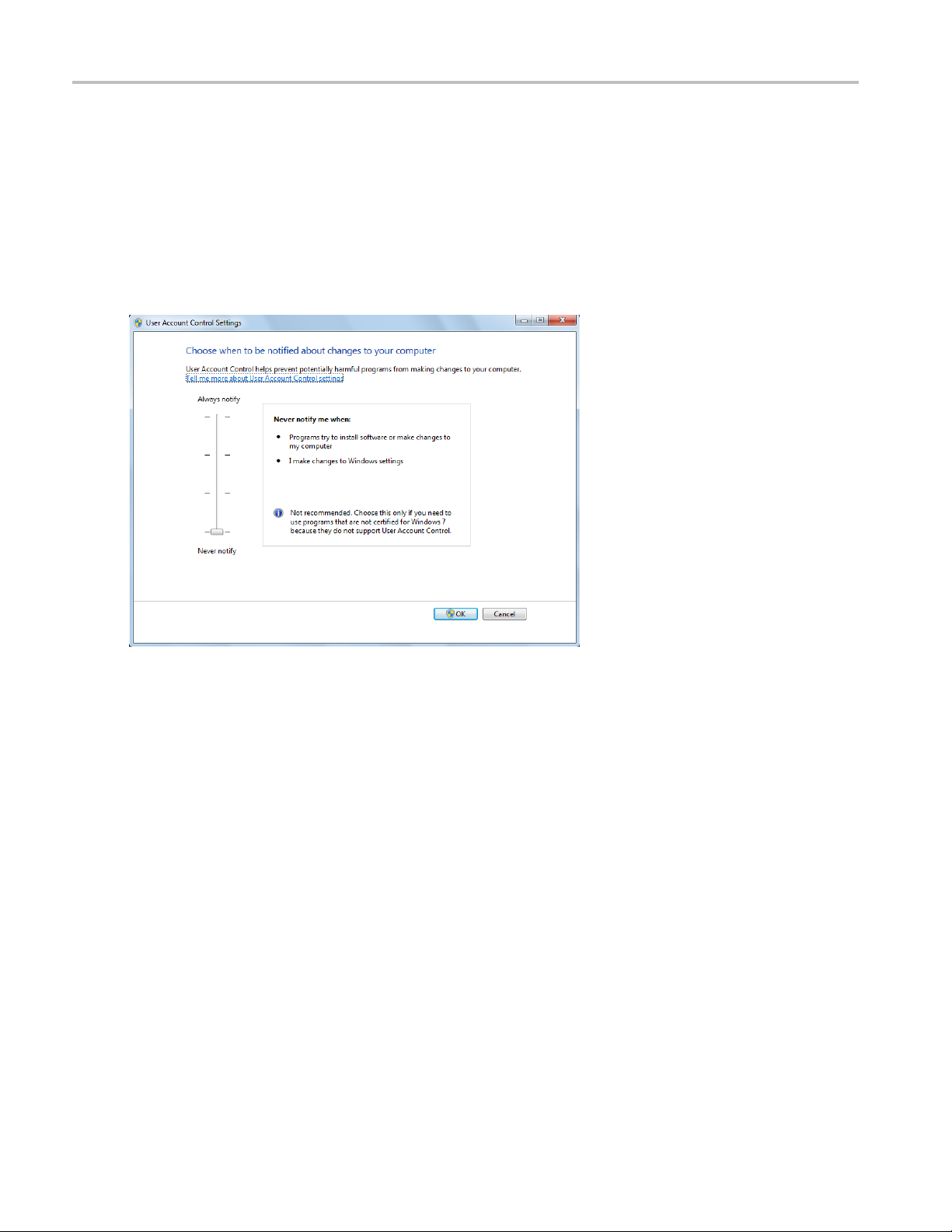
Windows 7 user account settings
Windows 7 instruments need to have the User Account Control Settings set to Never Notify. To set
User Account Control Settings:
1. Go to Control Panel > User Accounts > Change User Account Control settings.
2. Set the Notify slider to Never Notify as shown in the image.
8 TekExpress USB 3.0 Automated Solutions Printable Online Help
Page 17

Getting started Application directories and content
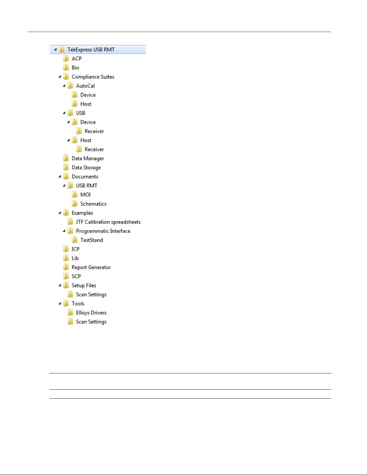
Application directories and content
TekExpress USB RMT is installed in the following directory path, depending on the Windows operating
system.
For Windows 7:
C:\Program Files (x86)\Tektronix\TekExpress\TekExpress USB RMT
For Windows XP and Windows XP-Embedded:
C:\Program Files\Tektronix\TekExpress\TekExpress USB RMT
The applic
ation directory and associated files are organized as follows:
TekExpress USB 3.0 Automated Solutions Printable Online Help 9
Page 18
Getting started Application directories and content
The following table lists the default directory names and their usage:
Table 3: Default directory names and their usage
Directory names Usage
InstallDir\TekExpress Contains the TekExpress application and associated
es.
fil
ekExpress\TekExpress USB RMT
\T
ntains files specific to TekExpress USB- RMT.
Co
10 TekExpress USB 3.0 Automated Solutions Printable Online Help
Page 19

Getting started File name extensions
Table 3: D efault directory names and their usage (cont.)
Directory names Usage
\TekExpress USB RMT\Compliance Suites Contains compliance specific sequence files. The
folders under this directory represent the devices
to be tested.
\TekExpress USB RMT\Compliance Suites\AutoCal Contains Autocal device and host s etting sequence
files.
\TekExpress USB RMT\Compliance Suites\USB Includes the Device folder.
\TekExpress USB RMT\SCP
\TekExpress USB RMT\ICP
\TekExpress USB RMT\Data Manager
\TekExpress USB RMT\Data Storage
\TekExpress USB RMT\Report Generator
\TekExpress USB RMT\Tools\Ellisys Drivers Includes the driver files for the Ellisys Protocol
\TekExpress USB RMT\Tools\Scan Settings Includes the default custom jitter profile tem plate
\TekExpress USB RMT\Documents Includes the Method of Implementation documents
\TekExpress USB RMT\Bin
\TekExpress USB RMT\Lib
\TekExpress USB RMT\Tools
xxx
Includes the TekExpress instrument and application
specific interface libraries.
Includes the TekExpress result management
specificlibraries.
Analyzer Hardware.
files.
and technical documentation for the application.
Includes the TekExpress Miscellaneous libraries.
File name extensions
Thesoftwareusesthefollowingfile name extensions:
File name extension Description
.awg
.pdf The PDF file that how to implement the test m ethod.
.s4p
.seq
.TekX
.wfm The waveform files created and kept in the AWG7XXX.
.xml
.mht
xxx
The AWG7XXX sequence files.
The S-Parameter files used to create waveforms when Channel
Emulation is set to Software.
The test sequence file.
The session file is saved in this format.
The encrypted XML file that contains the test specificconfiguration
information. The log file extension is also xml.
Test report file.
TekExpress USB 3.0 Automated Solutions Printable Online Help 11
Page 20
Getting started How to activate the license
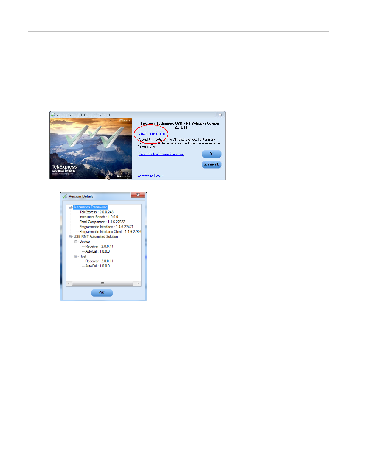
How to activate the license
Follow the steps below to activate the license:
1. Click Help > About TekExpress.
2. Click the View Version Details link to check the version numbers of the installed test suites.
12 TekExpress USB 3.0 Automated Solutions Printable Online Help
Page 21
Getting started How to activate the license
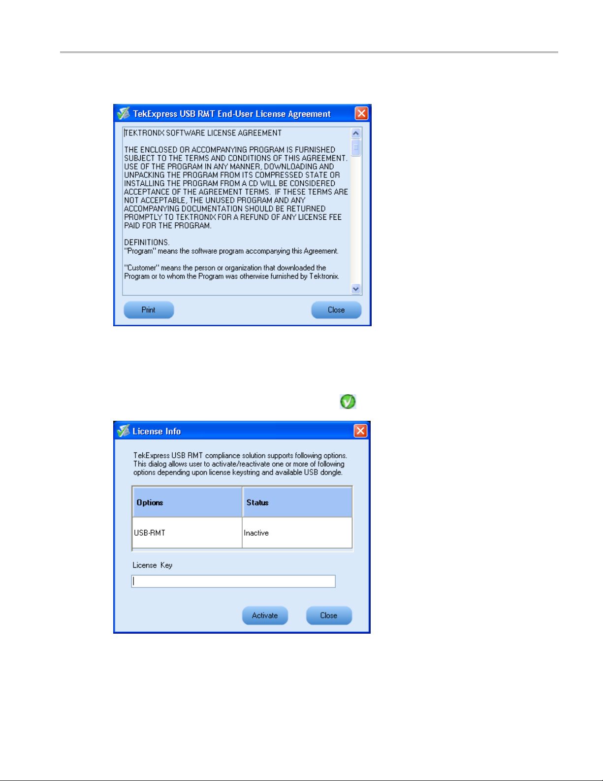
3. Click the View End-User License Agreement link to open the Tektronix USB-RMT End-User
[Software] License Agreement window. Click Print to print the License Agreement.
4. Click License Info to view the available software options. This window shows the license key and the
various options with their status (active or inactive) with the current license key.
5. If you are activating the license for the first time, the license key field is empty. To activate the license,
connect the USB dongle to your computer, enter the license key provided in the license key certificate,
ck Activate. If the activation is successful, a
and cli
sign is displayed next to the license key field.
6. If you are reactivating the license, click Reactivate, enter the new license key and click Activate.
TekExpress USB 3.0 Automated Solutions Printable Online Help 13
Page 22

Getting started Before you click Run
Before you click Run
After you first launch TekExpress, it creates the following folders on your computer:
\My Documents\My TekExpress
NOTE. Ensure that the “My TekExpress” folder has read and write access.
NOTE. If a user with a different Windows login ID launches TekExpress, a new
created under that user's
\My Documents\My TekExpress\USB RMT.
\My Documents\My TekExpress\USB RMT\Untitled Session. Every time the TekExpress
USBRMT.exe
Untitled Session folder is deleted when you exit TekExpress.
is launched a Untitled Session folder is created under USB RMT folder. The
My Documents
folder
My TekExpress
folder is
CAUTION. Each session has multiple files associated with it. Do not modify any of the session files and/or
s as this may result in loss of data or corrupted session files.
folder
The My TekExpr ess folder is created as a shared folder with share name as <domain><user
ID> My
name><user ID> My TekExpress
The a
TekExpress
bove shared folder is mapped as X: (X drive) on to the PC where TekExpress is running.
(or if the PC is not connected to domain then share name is <Computer
).
NOTE. If X drive is mapped to any other shared folder, TekExpress will display a Warning message
window asking to disconnect the X: drive manually.
Do the following before you click Run:
NOTE. Make sure to enable the network connectivity on the PC running the TekExpress application.
1. Map (see page 15) the shared My Te kExpress folder as X: (X drive) on all the instruments used
in test setup running Microsoft Windows Operating System. This share folder is used to save the
waveform files or any other file transfer operations.
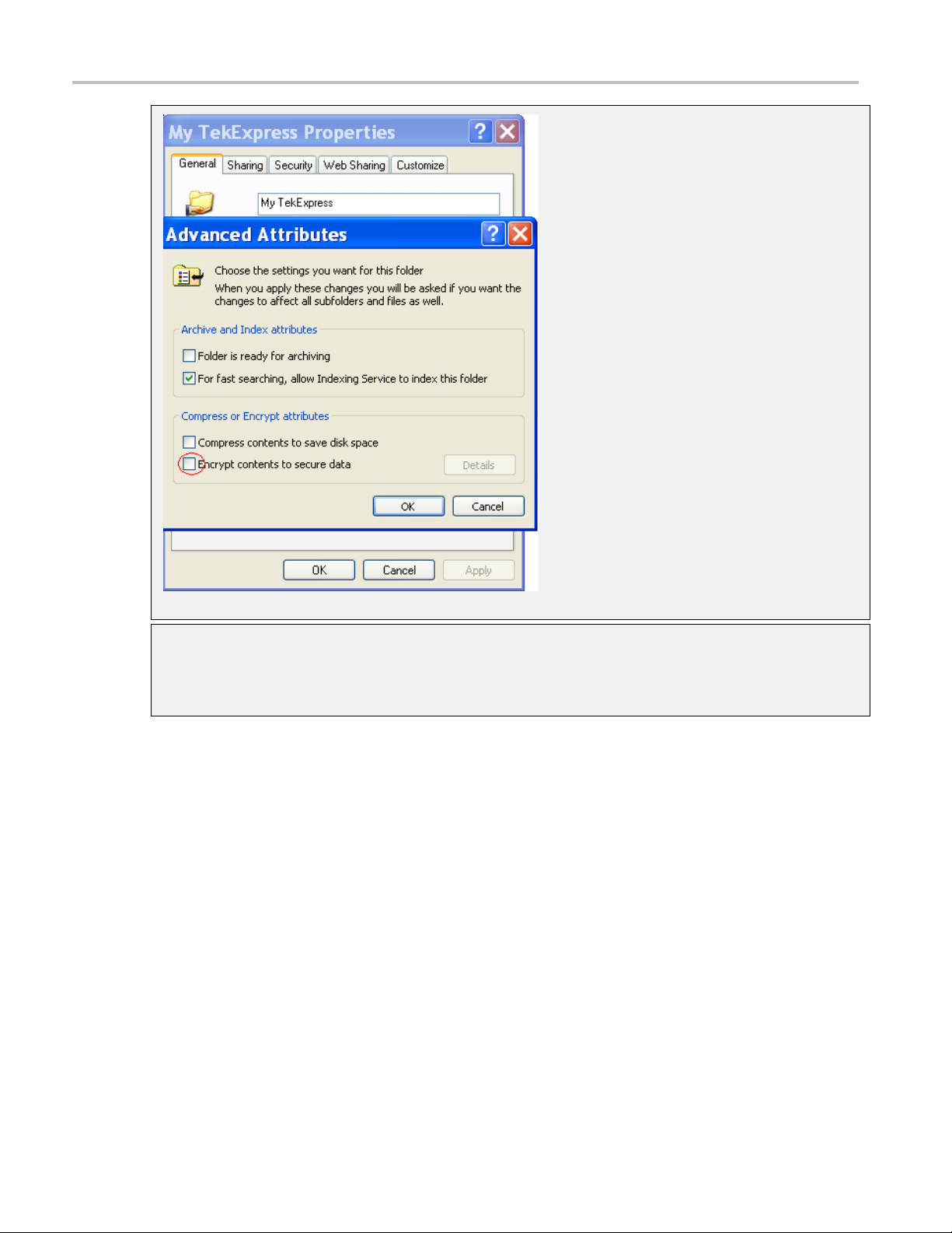
2. Right-click on the
My TekExpress folder and open the Properties dialog box. Select theGeneral tab
and then Advanced.IntheAdvanced Attributes window, ensure that the option Encrypt contents to
secure data is NOT selected. Click here
(see page 16) to view the picture.
14 TekExpress USB 3.0 Automated Solutions Printable Online Help
Page 23

Getting started Before you click Run
3. Ensure that the USB RMT setup files provided with TekExpress DVD are available on the respective
instruments. For more details, refer to the
Files
folder o
n the TekExpress DVD.
ReadmeFirst.txt located in the USB RMT S etup
4. Ensure that all the required instruments are properly warmed up, and that you do a Signal Path
Compensatio
n (SPC)
(see page 16). Add calibration of the AWG.
Mapping my TekExpress folder
To map the My TekExpress folder on the instruments, follow the steps below:
1. Open Windo
ws Explorer.
2. From the Windows Explorer menu, select Too l s > M a p Ne t wo r k dr i ve .
3. Select the Drive letter as X: (if there is any previous connection on X:, disconnect it first through
Tools > Disconnect Network drive menu of Windows Explorer).
4. In the Folder field, enter remote
My TekExpress folder path (for example, \\192.158.97.65\
John’s My TekExpress)
5. Determine the IP address of the PC where “My TekExpress” folder exists by doing the following:
Select Start > Run menu on the PC where My TekExpress folder exists.
Enter cmd and click Enter.
At command prompt, type ipconfig.
TekExpress USB 3.0 Automated Solutions Printable Online Help 15
Page 24
Getting started Before you click Run
Find SP
1. On the oscilloscope main menu, click Utilities menu.
2. Click Instrument Calibration option.
C by following the steps below (only needed if using an oscilloscope error detector):
16 TekExpress USB 3.0 Automated Solutions Printable Online Help
Page 25

Operating basics TekExpress application overview
TekExpress application overview
TekExpress is the Tektronix Compliance Test Automation Framework, developed to support current and
future test automation needs of customers. Developed using National Instruments' TestStand, TekExpress
leverages on
deploying automated test solutions for various serial standards in a relatively short time. The USB receiver
solution supports test automation in the TekExpress framework providing customers with a complete
solution for USB 3.0 receiver verification, characterization, debug, and compliance.
the capabilities of Microsoft .NET framework. It is a highly modular architecture that enables
Starting the application
The application uses a USB dongle that contains the license key. Insert the dongle into an available USB
port before starting the application. This dongle must be present on the PC or the instrument hosting
the TekExpress application.
The application also checks for a file, called
is not found, instrument discovery is performed before launching TekExpress. The
contains information regarding instruments available on network.
When the application starts, it checks for the appropriate license key. If the valid lic ense key is not present,
the application switches to the “Demo” mode. If the application fails to detect the dongle, it continues
toruninDemomode.
To start the application, do one of the following:
Click Start > Programs > Tektronix > TekExpress > TekExpress USB RMT. Other applications
follow similar pattern.
Double-click the icon on the desktop.
If you have previously saved a session, double-click the session file stored under My
TekExpress\USB-RMT
When the application is launched it displays the splash screen providing launch information. The
application also checks for the presence and validity of the USB dongle.
.
Resources.xml, located in My TekExpress folder. If this file
Resources.xml fi le
TekExpress USB 3.0 Automated Solutions Printable Online Help 17
Page 26

Operating basics Starting the application
NOTE. If the application was not terminated properly during the last use, a dialog box asks to recall the
previously unsaved session.
18 TekExpress USB 3.0 Automated Solutions Printable Online Help
Page 27
Operating basics Resizing the application window
Resizing the application window
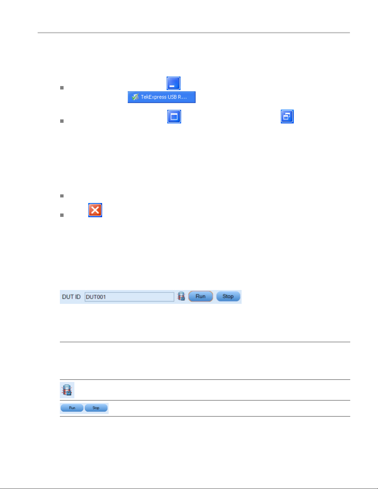
To minimize the application, click on the application title bar. To restore the application to its
previous siz
To maximize the application, click . To restore it to previous size, click on the application
title bar.
e, select
Exiting the application
To exit the application, do one of the following:
Click File > Exit.
Click on the application title bar.
Global controls
The menus and controls that appear outside the individual tabs are called “Global Controls”. These are
used to specify the devices to be tested.
in the Windows task bar.
Table 4: Controls and functions
Control name Function
DUT
xxx
TekExpress USB 3.0 Automated Solutions Printable Online Help 19
The device ID is specified at the global level and the
information is stored in the default location for all data
files. This field cannot be empty and does not allow these
special characters (.,..,...,\,/:?”<>|*). The maximum length
of characters allowed is 32.
This indicates when the disk memory goes below ~1 GB of
available space on the device running TekExpress.
You are able to run, pause, resume and stop the tests.
Page 28
Operating basics File menu
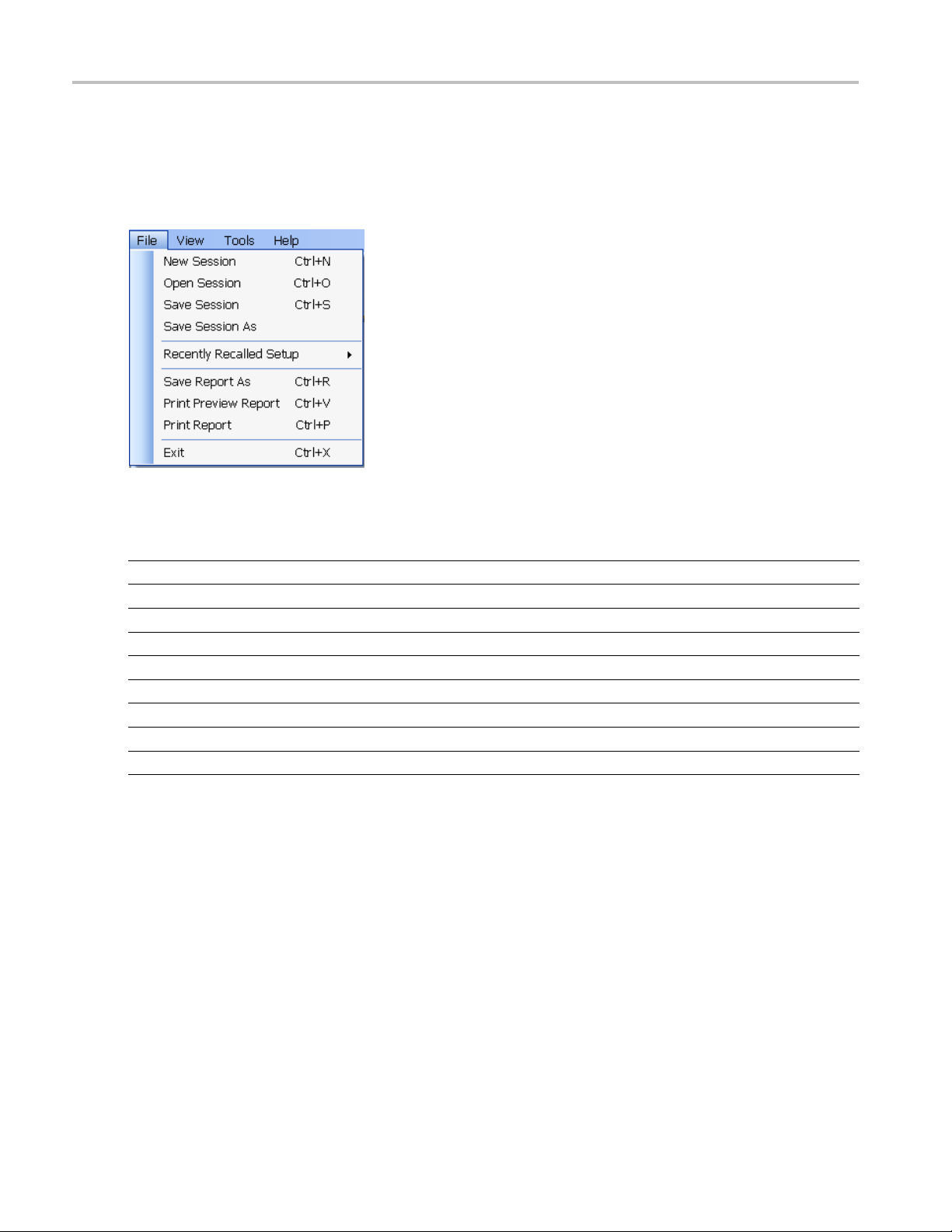
File menu
Click File on the application menu bar.
The File menu has the following selections:
Menu Function
New Session Starts a default session of TekExpress.
Open Session Opens a saved session.
Save Session Saves the session.
Save Session As Saves a session in a different name.
Recently Recalled Setup Lists all the recent and previously recalled setup files.
Save Report As Saves the report in user specified location.
Print Preview Report
Print Report
Exit
xxx
Previews the report before printing.
Opens the Windows “Print” dialog box.
Closes the application.
20 TekExpress USB 3.0 Automated Solutions Printable Online Help
Page 29
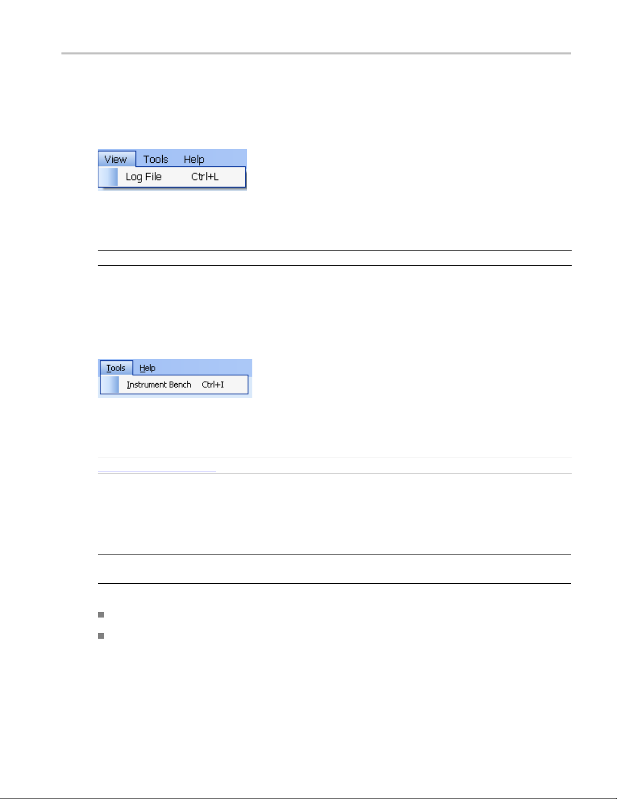
Operating basics View menu
View menu
Click View on the application menu bar.
The View menu has the following selections:
Menu Function
Log File
xxx
Opens the log (log.xml) file in the default viewer.
Tools menu
Click Tools on the application menu bar.
The Tools menu has the following selections:
Menu Function
Instrument Bench (see page 21) Opens a dialog box showing the list of instruments attached to the test setup.
xxx
Instrument Bench
Instrument Bench window shows the list of VISA and Non-VISA resources found on different
The
interfaces/connections. It serves two purposes at the launch of TekExpress:
NOTE. The Ellisys analyzer is a Non-VISA Resource and should be checked in order for TekExpress to
recognize the Ellisys analyzer.
Discovers the connected instruments.
Confirms the instrument connection setup.
TekExpress USB 3.0 Automated Solutions Printable Online Help 21
Page 30
Operating basics Tools menu
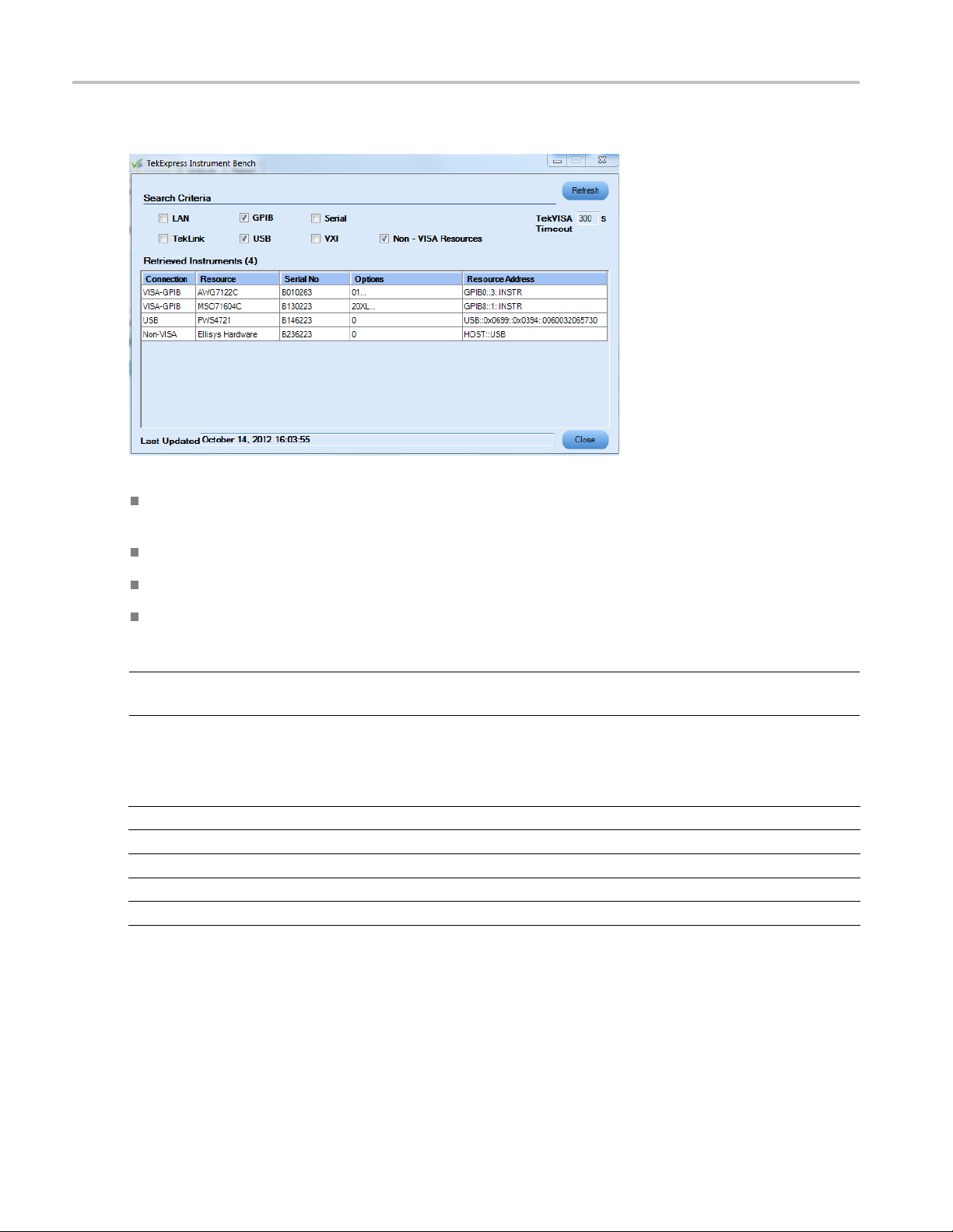
Click Tools > Instrument Bench to open the TekExpress Instrument Bench dialog box:
Search Criteria: The various connections on which you can search. Non-VISA Resources are the
instruments that cannot be searched using TekVISA.
Retrieved Instruments: Displays the count and details of instruments that were discovered.
Last Upd
ated: Displays the time when the last time search was performed.
TekVISA Refresh Timeout (Seconds): This time out specifies the maximum time that TekExpress
can wai
t for TekVISA update.
NOTE. TekExpress uses TekVISA for instrument search. Ensure that TekVISA is running on your system
before you refresh the instrument bench window.
Table 5: Retrieved Resources properties in the Instrument Bench window
Title Description
Connection Shows the type of connection with the instrument.
Resource
Serial Number Shows the serial number of the resource.
Options Shows the options available on the instrument.
Resource Address
xxx
1
The option column displays the options that fitinthefield. To view complete options on the instrument, move the mouse cursor over the option.
Shows the name of the resource.
1
Shows IP Address/Port number of the resource.
22 TekExpress USB 3.0 Automated Solutions Printable Online Help
Page 31

Operating basics Help menu
Table 6: Button controls on Instrument Bench dialog box
Button Function
Refresh The application searches on the selected connection for resources. While
searching res
Discovery window shows the connection currently being scanned and the
percentage of task completed.
ources it shows the Instrument Bench discovery window. The
Close Closes the
xxx
Help menu
Click Help on the application menu bar.
The Help menu has the following selections:
Selection Description or Function
TekExpress Help
About TekExpress (see page 12) Displays application details such as software name, version
Activate License
xxx
dialog box.
Displays TekExpress Help (F1).
number and copyright.
Displays available software options and also about license
activation.
TekExpress USB 3.0 Automated Solutions Printable Online Help 23
Page 32

Operating basics Help menu
24 TekExpress USB 3.0 Automated Solutions Printable Online Help
Page 33

How to Select the test(s)
Select the test(s)
The application supports the following DUT types for Receiver Compliance and Characterization testing
compliance.
Device
Host
Use the Select panel to select either a compliance test or a margin test (which allows the sweeping of
SJ frequencies) to configure and run.
The Select panel provides the following functions:
Version
Specifies the USB version number.
Ttype
DU
Specify either Device or Host as DUT. This specification will ensure that the appropriate channel model
s used when using software channel emulation.
i
TekExpress USB 3.0 Automated Solutions Printable Online Help 25
Page 34

How to Configure and run the test(s)
Channel emulation
A channel emulator duplicates (provides an emulation of) the function of the actual physical channel and
cable, so that the emulated channel behaves like the actual physical channel. The default is to use the USB
3 c ompliance channels. Select one of the following:
Hardware: Select this option to test the application using a USB cable instead of S-parameter files.
Software: Select this option to emulate the channel using the S-parameter files.
Electrical test specification
Specifies the version number of the Electrical Compliance Test Specification (CTS) document. The CTS
document provides the compliance criteria and test descriptions for SuperSpeed USB devices, hubs and
host controllers that conform to the Universal Serial Bus 3.0 specification. These criteria address the
electrical requirements for a SuperSpeed physical layer design.
All signal impairments (such as De-emphasis, SSC Profile, RJ, and others) are automatically configured
based on the version of the CTS selected. Calibration of the signal impairments is required to ensure that
the output of the AWG meets the specifications.
Device channel emulation
This depicts the type of system configuration.
Select: Includes/Excludes any test for analysis.
Tes t Na me : Displays the name of the test.
Once you select a row, the following options are available:
Table 7: Button controls on the select panel
Button Description
Opens the configuration panel for the selected test.
Opens the PDF of method of implementation (MOI) for the selected test.
Opens the schematic for the selected test. T his is useful if you want to
verify the test setup before r unning the test.
Opens the Calibration Wizard utility.
xxx
Configure and run the test(s)
The configuration panel is used to create, view, and edit the parameters associated with the acquisition and
the analysis of the selected test.
26 TekExpress USB 3.0 Automated Solutions Printable Online Help
Page 35

How to Configure and run the test(s)
Available functions:
Choose betwe en running the tests in a Compliance or User Defined mode. If you wish to change to
User Defined mode, you are prompted with a m essage “If you make changes to a test, the test may no
longer be compliant”. In User-defined mode you can change parameters such as the SJ Frequency and
ude, SSC profile, the amount of RJ and other parameters.
amplit
Store compliance mode values.
Change the parameters associated with analysis configuration.
Specify the error detection method.
Specify loopback initialization (see page 28) and loopback validation (see page 29).
Change the test limits (allowed number of bit/symbol errors).
upper half of the Configure panel has general parameters that are common for all the tests under the
The
selected test suite that are editable. The lower half of the Configure panel has test specific parameters.
NOTE. If any of the test parameters are grayed, it means that these parameters cannot be modified in
compliance mode. When you switch to user-defined mode, these parameters are editable.
TekExpress USB 3.0 Automated Solutions Printable Online Help 27
Page 36

How to Configure and run the test(s)
Table 8: Test parameters
Parameters to c
Acquire
Analyze
Limits
Comments You can specify a comment up to 256 characters long for the selected test.
Default settings
onfigure
Description
Typically, it
applicable.
Shows the various parameters related to analysis of a selected test. You can include/exclude
various jitter parameters based on amplitude and frequency. Double-click on the row to
include/exc
parameters:
Applies to a specific test. You can view the Maximum Allowable number of errors for error
detection
error detector hardware is used. If the errors detected by Ellisys
Error Detector are more than the specified limit (should be Less Than or Equal To), then
the test p
to manually enter the error count.
The default compliance settings will be restored.
Accepts all changes that you made.
shows any acquisition parameters, but for RMT testing no acquire parameter is
lude the parameter from the drop-down menu. You can also set the following
Specify whether to create waveforms or use prerecorded waveforms for signal
generation.
Specify whether or not to save the created waveforms.
. The application automatically detects the number of errors for each test point, if
(see page 28) or the Scope
oint is marked as FAIL. If other methods of error detection are used, you need
Dismisses the dialog box and does not apply changes.
xxx
Click Run in the Select panel to run the selected tests.
Ellisys error detector
Ellisys USB Explorer 280 Analyzer/Generator is a USB 3.0 symbol error detector. The hardware is
identical to the standard Ellisys Super Speed USB 3.0 protocol analyzer/generator. When used with
e Tektronix AWG7102, AWG7122B, or AWG7122C high-speed signal generator and automation
th
software from Tektronix, the EX280-CT completes the solution for USB 3.0 receiver testing.
Loopback initialization
hen running the receiver jitter tolerance tests, USB-RMT is configured to automatically put the
W
device into loopback mode per the loopback sequence that is defined in the CTS. Please contact your
Tektronix representative if your device requires an alternative method to be put into loopback mode.
In the loopback mode, the receiver loops back the data it receives and any difference in the pattern
sent from the signal generator and returned from the DUT is counted as an error.
28 TekExpress USB 3.0 Automated Solutions Printable Online Help
Page 37

How to Configure and run the test(s)
Loopback validation
Loopback validation is a procedure to verify if the DUT has gone into loopback successfully or
not. The way loopback validation is done depends on the test selected and also on the ‘Waveform
Creation Option’.
If user selects ‘Normative Receive Jitter Tolerance Test (TD1.6) - step through certain levels,’ the
general parameter 'Loopback Validation' value is set to ‘First time only’ in the configuration panel and
is applied t
If user selects ‘Informative SJ Sensitivity Margin Test - sweep through a range,’ the general parameter
'Loopback
is done before every jitter pattern for any waveform creation option selected (‘Use Pre-Created’ or
‘Use Pre-Created and create if not available’ or ‘Always Create’).
If user selects ‘Informative SJ Sensitivity Margin Test - sweep through a range,’ the general
parameter 'Loopback Validation' value is set to ‘First time only’ in the configuration panel, and
loopback validation is done only before the first pattern for the 'waveform creation option*' set to
'Use Pre-Created' or 'Use Pre-Created and create if not available.'
If user selects ‘Informative SJ Sensitivity Margin Test: sweep through a range,’ the general parameter
'Loopback Validation' is set to ‘First time only’ in the configuration panel, and the AWG is turned on
before the first pattern in that AWG when the ‘waveform creation option*’ is set to Always Create*.
o all selected DUT / Channel Emulations.
Validation' value is set to 'Always' in the configuration panel, and loopback validation
If loopback validation fails for any test selected, and the configure general parameter ‘DUT Power
Cycle Method’ value is set to 'Tektronix Power Supply' or 'AWG', then the instrument automatically
r cycles three times during loopback validation, and displays a message to Retry, Continue, or
powe
Cancel if the loopback validation fails.
Perform Warm Reset' is set as Yes (Device DUT Informative test), then the instrument does two
If '
warm resets before doing an automatic power cycle.
* Waveform creation option parameters:
Always Create: Application creates and uses all waveforms during the text execution.
Use Pre-Created and create if not available: Application checks for WFMs in the AWG, if they
are available will go ahead and use them else they will be created and then used by the a pplication.
Pre-Created (for informative tests): Application checks for the WFMs in AWG; if they are
available will go ahead and use them else the application will prompt user that WFMs are not
available and will continue the test.
Pre-Created (for normative tests): Application uses the supplied *.AWG files during the test
execution.
TekExpress USB 3.0 Automated Solutions Printable Online Help 29
Page 38

How to Calibration (Auto Cal)
Calibration (Auto Cal)
The auto calibration function addresses receiver calibration requirements for the USB 3.0 standard. Auto
calibration compensates the patterns for specific jitter parameters (de-emphasis, Random jitter, sinusoidal
jitter and st
The procedure sequences through all the patterns, with each pattern calibrated independently. These
values are u
loopback.
ressed eye).
sed for the jitter-controlled generation of patterns which will be injected into the DUT during
The design
impairments) meets the compliance test specification within a certain tolerance range.
To perfor
uniform step size and computes the transfer function b etween the measured and input values.
The sign
DPOJET and SigTest as per the CTS.
The cal
appropriate polynomial fit algorithm for all the target values which gives the characteristic curve. The
respective c alibrated values are derived from the characteristic curve.
The blue square icons on the calibration graph plot represent the measured jitter values. The black square
icons represent the calibrated values.
engineer needs to ensure that the amount of jitter components (also known as target
m the calibration, the application varies the target parameter through a predefined range and a
al generation for calibration is done using an AWG. The measurement methodology can be
ibration results can be viewed at any time as values or graphical plots. The application uses an
See also:
Auto calibration schematics (see page 131)
Auto Calibration wizard overview (see page 122)
30 TekExpress USB 3.0 Automated Solutions Printable Online Help
Page 39

How to View and Select Connected Instruments
View and Select Connected Instruments
Viewing Conne
The Tools > Instrument Bench menu item is used to discover connected instruments required for the
tests. The ap
the Instrument Bench dialog box resumes operation and lists the instrument-related details based on the
selected search criteria.
NOTE. When the TekVISA Instrument Manager checks for connected Instruments, the Instrument Bench
dialog box does not respond.
Select the search criteria and click Refresh to let the TekVISA Instrument Manager detect and display
available instruments.
cted Instruments
plication uses TekVISA to d iscover the connected instruments. Once the operation is done,
The TekVISA Refresh Timeout (Seconds) field sets the time within which if the TekVISA Instrument
Manager does not find the instruments, the TekExpress application resumes the current operation.
Selecting Non-VISA Resources causes the instrument to search for all instruments supported by
TekExpress that are not communicating over the VISA. An example of this is the Ellisys error detector.
TekExpress USB 3.0 Automated Solutions Printable Online Help 31
Page 40

How to View and Select Connected Instruments
Selecting Connected Instruments
Yo u can view the i nstruments connected in the Configuration panel. The upper half of the panel displays
the general parameters for the tests under the selected test suite.
Choose the instruments from the drop-down list as shown in the following figure:
Select the “Do Not Use” option in the drop-down list for those instruments which are optional. For
le, if the error detection method is selected as “Do not use”, the application prompts you to enter the
examp
error count after each test point.
NOTE. The list of instruments displayed is specific to the selected test suite. It does not show all the
connected instruments.
32 TekExpress USB 3.0 Automated Solutions Printable Online Help
Page 41

How to View the Progress of Analysis
ViewtheProgressofAnalysis
You can view the result s ummary in the Analyze panel for the selected test. The result value updates
as each test point is executed,
Analysis Table
The application automatically generates all of the required waveforms for each frequency/amplitude as
specified using SerialXpress.
Parameter Description
Frequency
Amplitude
Error Displays any detected errors.
Pass/Fail Displays Pass/Fail status for each test point.
xxx
The test points that have not been executed are shown with a “To be Started” status. A summarized status
of the currently running test is shown on the Status Messages panel.
TekExpress USB 3.0 Automated Solutions Printable Online Help 33
Lists the various SJ frequencies selected in the configure panel after its generation from the AWG.
Lists the various amplitude for each jitter frequency as selected in the configure panel.
Page 42

How to View the Report
A graph is plotted automatically and updated after the execution of every generated frequency and
amplitude. You can view the graph in two modes – Log-Log
graphical vie
The Status Messages window timestamps all runtime messages and displays them. Do the following:
Display Status: Enable/Disable s tatus messages.
Auto Scroll: Scroll status messages automatically.
Clear All: Clears all sta tus me ssages in Status Window.
Save Status: Saves all status messages in text file. Displays a standard save file window and saves the
status messages in the user specified file.
NOTE. The Status Messages window is dockable and can be resized.
w is set to 100%.
(see page 34) and Linear (see page 34).The
Log-Log Graph
Displays the graph in logarithmic scale for both amplitude and frequency.
View
Linear Graph
Displays the graph in linear scale for both amplitude and frequency.
the Report
r the analysis, a report is automatically generated. The report shows the results of the tests, including
Afte
device information and pass/fail status of each test point.
NOTE. If a test is aborted, the report is generated for the all completed test points.
The report displays the DUT, the date and time that was run, and execution time. Test information like the
DUT, Execution Time, Compliance Mode (Yes or No), and Overall Test Result (Pass or Fail) are shown.
Instrument information like the models, serial numbers, and firmware/software versions are shown. A
table displays the Test Name, Measurement Details, Limit values, Test Result, Analysis Execution time
andsoon.
The Report View Area contains an HTML version of the report template. Select any area of the report and
copy it to the clipboard to make it available for other applications.
34 TekExpress USB 3.0 Automated Solutions Printable Online Help
Page 43

How to View Test Related Files
View Test Related Files
All the test related files for currently selected tests are always saved under My Documents\My
TekExpress\USB-RMT\Untitled Session
When you save a session, it is saved with the session name under the path
TekExpress\USB-RMT\SessionName
The session that is currently running is stored in the same path as “Untitled” until you save it.
WARNING. Do not save a session named “Untitled” or “Backup” because these are application-specific
files and are deleted when you exit the application.
A session folder can contain results for more than one DUT, and a DUT folder can contain more than one
run data folder marked by date-time stamp as folder name.
Here is an example image of data storage:
.
My Documents\My
for future references.
TekExpress USB 3.0 Automated Solutions Printable Online Help 35
Page 44

How to View Test Related Files
36 TekExpress USB 3.0 Automated Solutions Printable Online Help
Page 45

Application Examples USB-RMT Equipment Setup: Device
USB-RMT Equipment Setup: Device
You need the following equipment to set up the application:
Required equipment Model supported
Signal Source Tektronix AWG7102, AWG7122B, or AWG7122C
Real Time Oscilloscope Tektronix DPO/DSA70000, DPO/DSA70000B, or DPO/DSA70000C Series
Tektronix MSO70000 or MSO70000C Series
Specified mo
supported
Error Detector/Analyzer DPO72004B, DPO72004C, DSA72004B, DSA72004C, DPO71604B,
DPO71604C, DSA71604B, DSA71604C, DPO71254B, DPO71254C,
DSA71254B
MSO71604C, MSO72004, MSO72004C
Ellisys Protocol Analyzer
Test Fixture
Tektronix Power Supply PWS4205, P W S4305, PWS4323, PWS4602, PWS4721
xxx
USB-IF test fixture or Tektronix test fixture
del oscilloscopes with more than 12.5 GHz sampling rate are
, D SA71254C, MSO71254,MSO71254C, MSO 71604,
TekExpress USB 3.0 Automated Solutions Printable Online Help 37
Page 46

Application Examples Testing a Device Using Normative Test Approach
Testing a Device Using Normative Test Approach
In the Normative test approach, the frequencies and amplitude considered for analysis are provided in the
specifications document. Follow the steps below for testing a device with error detector:
1. Select the DUT Type as Device.
2. Enter the DUT ID.
3. Select the Channel Emulation as Hardware, if using the USB-IF test fixtures and a 3 meter cable.
4. Select theTe st N am e as Normative Receiver Jitter Tolerance Test.
5. If you want to verify the test setup before running the test(s), click Show Schematic (see page 107).
6. Clic
7. Select the Analyze tabintheconfiguration screen to include or exclude the various frequencies and
38 TekExpress USB 3.0 Automated Solutions Printable Online Help
k Configure to configure the test parameters. Observe that the default settings are in Compliance
mode. If you would wish to change the settings to User Defined, you are prompted with a message “If
you make changes to a test, the test may no longer be compliant”.
amplitude (as specified in the specifications document) for jitter parameters.
Page 47

Application Examples Testing a Device Using Normative Test Approach
8. Select the Limits tab to see the Maximum Allowable limit for error detection. If the number of
errors d
To), then the compliance is marked as FAIL.
etected by the error detector is more than the specified limit (should be Less Than or Equal
NOTE. Yo u can detect errors using either the oscilloscope error detector or the Ellisys instrument,
or manually with other error detectors. If the oscilloscope error detector or the Ellisys instrument is
connected, the application automatically counts the number of errors. Otherwise, the application displays
a dialog box in which to manually enter the error count.
TekExpress USB 3.0 Automated Solutions Printable Online Help 39
Page 48

Application Examples Testing a Device Using Normative Test Approach
9. Click Apply to apply the new settings for the selected test. Click Close.
10. Click Run t
The status of the tests is displayed in the Analyze panel, which shows the status of the instruments
being init
graphical results of each test point.
o run the selected tests.
ialized, and waveforms being generated for various frequencies. You can also view the
11. The report is automatically updated after each test point and can be viewed in the Reports tab.
40 TekExpress USB 3.0 Automated Solutions Printable Online Help
Page 49

Application Examples Testing a Device Using Informative Test Approach
Ellisys Error Detector
Ellisys USB Explorer 280 Analyzer/Generator is a USB 3.0 e rror detector. The hardware is identical
to the standard Ellisys Super Speed USB 3.0 protocol analyzer/generator. When used with Tektronix
AWG7122B, high-speed signal generator, and automation software from Tektronix, the EX280-CT
completes th
e solution for USB 3.0 receiver testing.
Testing a Device Using Informative Test Approach
In Informative test approach, the frequencies considered are customizable beyond compliance. This
approach is used to test the margin of the DUT.
Follow the steps below for testing a device with error detector:
1. Select Device as the DUT Type.
2. Enter the DUT ID.
3. Select
4. Select Informative SJ Sensitivity Margin Test as the Test Name.
5. If you want to verify the test setup before running the test(s), click Show Schematic
6. Click Configure to configure the test parameters. Observe that the default settings are in User
Hardware as the Channel Emulation.
(see page 116).
Defined mode.
7. Select the Analyze tabintheconfiguration screen and select the following parameters:
TekExpress USB 3.0 Automated Solutions Printable Online Help 41
Page 50

Application Examples Testing a Device Using Informative Test Approach
Parameter Description
Scan Method Select the scan method to locate a failed point:
Linear Pass to Fail (see page 44)
Select Scan Parameter Preset
Scan Type
Scan Parameter
Preset File
Start
Frequency(MHz)
End
Frequency(MHz)
Incremen
Frequency
Sj Start Value
Sj End Value
Sj increment
xxx
1
2
1
The Scan Type parameter is a read-only parameter for information purposes.
The path to the parameter preset file.
1
2
Specify the
SJ start frequency in the MHz.
Specify the SJ end frequency in MHz.
2
t
2
2
2
2
own if the Scan Method is set to Select Scan Parameter Preset.
Only sh
Only shown if the Scan Method is set to Linear Pass to Fail.
Specify the incremental frequency in MHz.
Specify the jitter start value in ps.
Specify the jitter end value i n ps.
Specify the incremental value in ps.
8. Selecting Select Scan Parameter Preset adds the Scan Parameter Preset File to the Parameters list.
Selecting the Value opens the Custom Jitter Profile-RMTDefaultScandialog box. Use this dialog
box to enter values for Frequency, Start Sj, Stop Sj, and Step Sj.
42 TekExpress USB 3.0 Automated Solutions Printable Online Help
Page 51

Application Examples Testing a Device Using Informative Test Approach
Use the check box in each row to enable or disable tests to execute on the DUT. Tests are executed
in the order listed.
Selecting a test row in the table updates the values in the edit fields. Enter new values in the edit
fields and click Update to set the values for the selected test row.
To insert a new test row above the selected row, enter new values in the edit fields and click Insert.
Click Clear to clear all the values in the edit fields.
Click Save and enter a file name to save the table settings as a Scan Parameter Pres et File to
the default location.
Click Recall to recall (load) a saved file or preset.
Click Reset to clear the entire table.
9. Select the Limits tab to see the Maximum Allowable limit for error detection. If the number of
errors detected by the error detector is more than the specified limit (should be Less Than or Equal
To), then the comp
10. Click Apply to apply the new settings for the selected test. Click Close.
11. Click Run to run the selected tests.
liance is marked as FAIL.
TekExpress USB 3.0 Automated Solutions Printable Online Help 43
Page 52

Application Examples Testing a Device Using Informative Test Approach
The status of the tests is displayed in the Analyze panel, which shows the pass or fail results of each
jitter frequency and amplitude.
12. The rep
ort is automatically updated after each test point and can be viewed in the Reports tab.
Linear Pass to Fail
Uses the specified start amplitude and increases the amount of jitter by the step size until the failure
point is located.
44 TekExpress USB 3.0 Automated Solutions Printable Online Help
Page 53

TekExpress Programmatic Interface About the Programmatic Interface
About the Programmatic Interface
The Programmatic interface allows you to seamlessly integrate the TekExpress test automation application
with the high-level automation layer. This also allows you to control the state of TekExpress application
running on a l
For simplifying the descriptions, the following terminologies are used in this section:
TekExpress Client: A High level automation application that communicates with TekExpress using
TekExpress Programmatic Interface.
TekExpress Server: The TekExpress application when being controlled by TekExpress Client.
TekExpress leverages .Net Marshalling to enable the Programmatic Interface for TekExpress Client.
TekExpress provides a client library for TekExpress clients to use the programmatic interface. The
TekExpress client library is inherited from .Net MarshalByRef class to provide the proxy object for the
. The TekExpress client library maintains a reference to the TekExpress Server and this reference
clients
allows the client to control the server state.
ocal or a remote PC.
TekExpress USB 3.0 Automated Solutions Printable Online Help 45
Page 54

TekExpress Programmatic Interface To enable remote access
Click the following links to get details on them:
What does one need to develop a TekExpress Client ?
While developing TekExpress Client one needs to use the TekExpressClient.dll. The client can be a VB
.Net, C# .Net, TestStand or web application. The examples for interfaces in each of these applications
Samples folder.
are in
References Required
TekExpressClient.dll has internal reference to IIdlglib.dll and IRemoteInterface.dllIIdlglib.dll has a
reference toTekDotNetLib.dll. IRemoteInterface.dll provides the interfaces required to perform the remote
automations. It is an interface that forms the communication line between the server and the client.
IIdlglib.dll provides the methods to generate and direct the secondary dialog messages at the client-end.
NOTE. The end-user client application d oes not need any reference to above mentioned DLL files. It is
essential to have these DLLs (IRemoteInterface.dll, IIdlglib.dll and TekDotNetLib.dll) in same folder
location as that of TekExpressClient.dll.
What steps does a client need to follow?
The following are the steps that a client needs to follow to use the TekExpressClient.dll to programmatically
control the server:
A client UI has to be developed to access the interfaces exposed through the s erver. This client needs to
TekExpressClient.dll to access the interfaces. Once the TekExpressClient.dll is loaded, the
load
client UI can call the specific functions to run the operations requested by the client. Once the client is up
and running, it has to do the following to run a remote operation:
1. The client needs to provide the IP address of the PC at which the server is running in order to connect
to the server.
2. The client needs to lock the server application to avoid conflict w ith any other Client that m
control the server simultaneously. “Lock” would also disable all user controls on server so that server
state cannot be changed by manual operation.
3. If any other client tries to access a se rver which is locked, it will get a notification that the server
is locked by another client.
4. When the client has connected to and locked the server, the client can access any of the programmatic
controls to run the remote automations.
5. Once the client operations are completed, the server needs to be “unlocked” by the client.
To enable remote access
ay try to
To access and remotely control an instrument using the TekExpress programmatic interface, you need to
change specific firewall settings as follows:
46 TekExpress USB 3.0 Automated Solutions Printable Online Help
Page 55

TekExpress Programmatic Interface To enable remote access
1. Access the Windows Control Panel and open the Windows Firewall tool (Start > Control Panel > All
Control Panel Items > Windows Firewall).
2. Click Advance Settings > Inbound Rules.
3. Scroll through the Inbound Rules list to see if the following items (or with a similar name) are shown:
TekExpress USB
TekExpress
4. If both items are shown, you do not need to set up any rules. Exit the Windows Firewall tool.
5. If one or both are missing, use the following procedure to run the New Inbound Rule Wizard and add
these executables to the rules to enable remote access to the TekExpress application.
Run the New Inbound Rule Wizard
1. Click on New Rule (in Actions column) to start the New Inbound Rule Wizard.
2. Verify that Program is selected in the Rule Type panel and click Next.
3. Click Browse in the Program panel and navigate to and select one of the following TekExpress
applications (depending on the one for which you need to create a rule):
4. TekExpress USB.exe
5. TekExpress.exe
NOTE. See Application directories and content
(see page 9) for the path to the application files.
6. Click Next.
7. Verify that Allow the connection is selected in the Action panel and click Next.
TekExpress USB 3.0 Automated Solutions Printable Online Help 47
Page 56

TekExpress Programmatic Interface Remote proxy object
8. Verify that all fields are selected (Domain, Private,andPublic)intheProfile panel and click Next.
9. Use the fields in the Name panel to enter a name and optional description for the rule. For example,
a name for the TekExpress USB application could be TekExpress USB TX Application.Add
description text to further identify the rule.
10. Click Finish to return to the main Windows Firewall screen.
11. Scroll through the Inbound Rules list and verify that the list shows the rule that you just entered.
12. Repeat steps 1 through 11 to enter the other TekExpress executable if it is missing from the list.
Enter Te
13. Scroll through the Inbound Rules list and verify that the list shows the rule that you just entered.
kExpress PI as the name.
14. Exit the Windows Firewall tool.
To use
1. Obtain the IP address of the instrument on which you are running TekExpress USB. For example,
2. On the PC from which you are accessing the remote instrument, use the instrument IP address as part
the remote access:
64.235.198.
134.
e TekExpress USB PI code to access that instrument. For example:
of th
object obj = piClient.Connect(“134.64.235.198”,out clientid);
Remote proxy object
The server exposes a remote object to let the remote client access and perform the server side operations
remotely. The proxy object is instantiated and exposed at the server-end through marshalling.
48 TekExpress USB 3.0 Automated Solutions Printable Online Help
Page 57

TekExpress Programmatic Interface Client proxy object
The following is an example:
RemotingConfiguration.RegisterWellKnownServiceType (typeof (TekExpressRemoteInterface), “TekExpress Remote interface”, WellKnownObjectMode.Singleton) ;
This object lets the remote client access the interfaces exposed at the server side. The client gets the
reference to this object when the client gets connected to the server.
For example,
//Get a reference to the remote object
remote
URL.ToString());
Object = (IRemoteInterface)Activator.GetObject(typeof(IRemoteInterface),
Client proxy object
Client exposes a proxy object to receive certain information.
For example,
//Register the client proxy object
WellKnownServiceTypeEntry[] e = RemotingConfiguration.Ge tRegisteredWellKnownServiceTypes();
TekExpress USB 3.0 Automated Solutions Printable Online Help 49
Page 58

TekExpress Programmatic Interface Client proxy object
clientInterface = new ClientInterface();
RemotingConfiguration.RegisterWellKnownServiceType(typeof(ClientInterface),
“Remote Client Interface”, WellKnownObjectMode.Singleton);
//Expose the client proxy object through marshalling
RemotingServices.Marshal(clientInterface, "Remote Client Interface");
The client proxy object is used for the following:
To get the se
condary dialog messages from the server.
To get the file transfer commands from the server while transferring the report.
Click here to see examples.
clientObject.clientIntf.DisplayDialog(caption, msg,iconType, btnType);
clientObject.clientIntf.TransferBytes(buffer, read, fileLength);
50 TekExpress USB 3.0 Automated Solutions Printable Online Help
Page 59

TekExpress Programmatic Interface Client Programmatic Interface: an Example
To know more on the topics below, click the links.
Secondary Dialog Message Handling
The secondary dialog messages from the Secondary Dialog library are redirected to the client-end when a
client is performing the automations at the remote end.
In the secondary dialog library, the assembly that is calling for the dialog box to be displayed is checked
and if a remote connection is detected, the messages are directed to the remote end.
File Transfer Events
When the client requests the transfer of the report, the server reads the report and transfers the file by
calling the file transfer methods at the client-end.
Client Programmatic Interface: an Example
An example of the client programmatic interface is described and shown as follows:
TekExpress USB 3.0 Automated Solutions Printable Online Help 51
Page 60

TekExpress Programmatic Interface Client Programmatic Interface: an Example
52 TekExpress USB 3.0 Automated Solutions Printable Online Help
Page 61

TekExpress Programmatic Interface Client Programmatic Interface: an Example
1. Connect to a server or remote object using the programmatic interface provided.
2. Get the client ID that is created when connecting to the remote object. This client ID is one of the
required parameters to communicate with the server.
NOTE. Server identifies the client with this ID only and rejects any request if the ID is invalid.
3. Lock the server for further operations. This disables the application interface.
NOTE. You can get values from the server or set values from the server to the client only if application is
locked.
4. Register for receiving noti fi cations on s tatus change even ts on the server. To register you need to
give a handler as a parameter.
NOTE. Whenever there is a change in the status of the server, all the clients registered with the server
receive a notification from the server.
5. Select the tests that you want to run through the programmatic interface.
6. Set the necessary parameters for each test.
7. Run the tests.
8. Poll for the status of the application.
NOTE. You can skip this step if you are registered for the status change notification and when the status is
Ready.
9. After completing the tests, get the results.
10. Create a report or display the results and verify or process the results.
nlock the server once you complete all the tasks.
11.U
12. Disconnect from the remote object.
Handler of Status Change Notification
1. Get the status. If the status is Wait or Error, get the information which contains the title, message
description, and the expected responses for the status.
2. Perform the actions based on the status information.
3. Set the response as expected.
TekExpress USB 3.0 Automated Solutions Printable Online Help 53
Page 62

TekExpress Programmatic Interface USB-RMT Application Command Arguments and Queries
USB-RMT Application Command Arguments and Queries
Connect through an IP address (see page 60)
Lock the server (see page 61)
Disable the popups (see page 62)
Set or get the DUT ID (see page 63)
Set the configuration parameters for a suite or measurement (see page 64)
Query the configuration parameters for a suite or measurement (see page 65)
Select a measurement (see page 66)
Select a suite (see page 67)
Run with set configurations or stop the run operation (see page 68)
Handle Error Codes (see page 99)
Get or set the timeout value (see page 69)
Wait for the test to complete (see page 70)
After the test is complete (see page 72)
Save, recall, or check if a session is saved (see page 74)
Unlock the server (see page 75)
Disconnect from server (see page 75)
Set or Get Configuration Parameters for Normative Receiver Test (see page 76)
Set or Get Configuration Parameters for Informative Test (see page 89)
General Parameters (see page 96)
string id
Name Type Direction Description
id string IN
xxx
Ready: Test configured and ready to start.
Running: Test running.
Identifier of the client that is
performing the remote function.
Paused: Test paused.
Wait: A popup that needs your inputs.
Error: An error is occurred.
54 TekExpress USB 3.0 Automated Solutions Printable Online Help
Page 63

TekExpress Programmatic Interface USB-RMT Application Command Arguments and Queries
string dutName
Name Type Direction Description
dutName string IN
xxx
The new DUT ID of the setup.
out bool saved
Name Type Direction Description
saved bool
xxx
OUT
This parameter is used as a check in SaveSession() and SaveSessionAs() functions.
Boolean representing whether the
current session is saved.
string ip
Address
Name Type Direction Description
ipAdress string IN
The ip address of the server to which the
s trying to connect. This is required to
client i
establish the connection between the server
and the client.
xxx
out string clientID
Name Type Direction Description
clientid
xxx
NOTE. If the dutName parameter is null, the client is prompted to provide a valid DUT ID.
NOTE. The server must be active and running for the client to connect to the server. Any number of
clients can be connected to the server at a time.
String OUT Identifier of the client that is connected to the
server.
clientId = unique number + ipaddress of the
client. For example, 1065–192.157.98.70
NOTE. When the client is disconnected, it is unlocked from the server and then disconnected. The id
is reused.
TekExpress USB 3.0 Automated Solutions Printable Online Help 55
Page 64

TekExpress Programmatic Interface USB-RMT Application Command Arguments and Queries
string dutId
Name Type Direction Description
dutId string
xxx
OUT The DUT ID of the setup.
The dutId parameter is set after the server processes the request.
string device
Name Type Direction Description
device string IN
xxx
Specifies the name of the device.
string suite
Name Type Direction Description
suite string IN
xxx
Specifies the name of the suite.
string test
Name Type Direction Description
test
string IN
Specifies the name of the test from
which to obtain the pass or fail status.
xxx
string parameterString
Name Type Direction Description
parameterString
xxx
string IN
Selects or deselects a test.
int rowNr
Name Type Direction Description
rowNr int IN
xxx
NOTE. When the client tries to lock a server that is locked by another client, the client gets a
notification that the server is already locked and it must wait until the server is unlocked. If the client
locks the server and is idle for a certain amount of time then the server is unlocked automatically
from that client.
Specifies the zero based row index of
the sub-measurement for obtaining
the result value.
56 TekExpress USB 3.0 Automated Solutions Printable Online Help
Page 65

TekExpress Programmatic Interface USB-RMT Application Command Arguments and Queries
out string[] status
Name Type Direction Description
status
string array
OUT The list of status messages generated
during run.
xxx
string name
Name Type Direction Description
name
string IN
The name of the session being
recalled.
xxx
The name parameter cannot be empty. If it is empty, the client is prompted to provide a valid name.
NOTE. When the run is performed, the status of the run is updated periodically using a timer.
string name
Name Type Direction Description
name
string IN
The name of the session being
saved.
xxx
The name parameter cannot be empty. If it is empty, the client is prompted to provide a valid name.
Once the session is saved under ‘name’ you cannot use this method to save the session in a different
name. Use SaveSessionAs instead.
string name
Name Type Direction Description
name
string IN
The name of the session being
recalled.
xxx
The same session is saved under different names using this method. The name parameter cannot be
empty. If it is empty, the client is prompted to provide a valid name.
bool isSelected
Name Type Direction Description
isSelected
xxx
bool IN
Selects or deselects a test.
TekExpress USB 3.0 Automated Solutions Printable Online Help 57
Page 66

TekExpress Programmatic Interface USB-RMT Application Command Arguments and Queries
string time
Name Type Direction Description
time string IN The time in seconds
which refers to the timeout
period.
xxx
The time parameter gives the timeout period, that is the time the client is allowed to b e locked and
idle. After the timeout period if the client is still idle, it gets unlocked.
The time parameter should be a positive integer. Else, the client is prompted to provide a valid
timeout period.
bool_verbose
Name Type Direction Description
_verbose bool IN
xxx
Specifies whether thec verbose mode
should be turned ON or OFF.
NOTE. When the session is stopped, the client is prompted to stop the session and is stopped at
the consent.
string filePath
Name Type Direction Description
filePath
string IN The location where the report must
be saved in the client.
xxx
NOTE. If the client does not provide the location to save the report, the report is saved at
C:\ProgramFiles.
NOTE. When the client is disconnected, the client is automatically unlocked.
out string caption
Name Type Direction Description
caption
xxx
String OUT
The wait state or error state message sent to
you.
58 TekExpress USB 3.0 Automated Solutions Printable Online Help
Page 67

TekExpress Programmatic Interface USB-RMT Application Command Arguments and Queries
out string message
Name Type Direction Description
message
xxx
String OUT The wait state /error state message to you.
out string[] buttonTexts
Name Type Direction Description
buttonTexts string array
OUT An array of strings containing the
possible response types that you can
send.
xxx
string response
Name Type Direction Descripti
response
string IN A string containing the response
type that
one of the strings in the string array
buttonTexts).
xxx
out string clientID
Name Type Direction Description
clientID
xxx
String OUT Identifier of the client that is connected to the
server.
clientID = unique number + ipaddress of the
client. For example, 1065–192.157.98.70
on
you can select (it must be
TekExpress USB 3.0 Automated Solutions Printable Online Help 59
Page 68

TekExpress Programmatic Interface ConnectThroughanIPAddress
Connect Through an IP Address
Table 9: Connect through an IP address
Command name Parameters Description Return Value Example
Connect()
xxx
string
ipAddress (see
page 55)
out string
clientID (see
page 55)
This method
connects the client
to the server.
(see page 55)
Note
The client provides
the IP address
to connect to the
server.
The server
provides a unique
client identification
number when
connected to it.
True or False.
m_Client = new Client()
//m_Client is a reference to the
Client class in the Client DLL
returnval as boolean
returnval = m_Client.Con-
nect(ipaddress,m_clientID)
Table 10: Test- Connect through an IP address
Parameters Description Return Value Example
Command name: Connect()
string ipAddress (see page 55)
out string clientID (see
page 55)
xxx
This method connects
the client to the server.
(see page 55)
Note
The client provides the
IP address to connect to
the server.
The server provides
a unique client
identification number
when connected to it.
True or False.
m_Client = new Client() //m_Client
is a reference to the Client class
in the Client DLL
returnval as boolean
returnval = m_Client.Con-
nect(ipaddress,m_clientID)
NOTE. The Fail condition for PI commands occurs in any of the following cases:
The server is LOCKED and the message displayed is “Server is locked by another client”.
The session is UNLOCKED and the message displayed is “Lock Session to execute the command”.
e server is NOTFOUND and the message displayed is “Server not found...Disconnect!”.
Th
When none of these fail conditions occur, then the message displayed is “Failed...”.
60 TekExpress USB 3.0 Automated Solutions Printable Online Help
Page 69

TekExpress Programmatic Interface Lock the Server
Lock the Server
Table 11: Lock the server
Command name Parameters Description Return Value Example
LockSession()
xxx
string clientID
(see page 59)
NOTE. The Fail condition for PI commands occurs in any of the following cases:
This method locks
the server.
(see page 56)
Note
The client must
call this method
before running
any of the remote
automations. The
server can be
locked by only one
client.
String value that
gives the status
of the operation
after it has been
performed.
The return value
is “Session
Locked...” on
success.
m_Client = new Client()
//m_Client is a reference to the
Client class in the Client DLL
returnval as string
returnval =
m_Client.LockServer(clientID)
The serv
er is LOCKED and the message displayed is “Lock Session to execute the command”.
The session is UNLOCKED and the message displayed is “Lock Session to execute the command”.
The server is NOTFOUND and the message displayed is "Server not found...Disconnect!".
When none of these fail conditions occur, then the message displayed is "Failed...".
TekExpress USB 3.0 Automated Solutions Printable Online Help 61
Page 70

TekExpress Programmatic Interface Disable the Popups
Disable the Popups
Table 12: Disable the popups
Command name Parameters Description Return Value Example
SetVerboseMode()
xxx
string clientID
(see page 59)
bool _verbose
(see page 58)
This method sets
the verbose mode
to either true or
false.
When the value
is set to true,
then any of the
message boxes
appearing during
the application
are routed to the
client machine
which is controlling
TekExpress.
When the value is
set to false, then all
the message boxes
are shown on the
server machine.
String that gives
the status of
the operation
after it has been
performed.
When Verbose
mode is set to
true, the return
value is “Verbose
mode turned on.
All dialog boxes
are shown to
client ...”.
When Verbose
mode is set to
false, the return
value is “Verbose
mode turned off.
All dialog box
will be shown to
server ...”.
m_Client = new Client()
//m_Client is a reference to the
Client class in the Client DLL
returnval as string
Verbosemodeisturnedon
return=m_Client.SetVerboseMode(clientID, true)
Verbosemodeisturnedoff
returnval=m_Client.SetVerboseMode(clientID, false)
NOTE. The Fail condition for PI commands occurs in any of the following cases:
The server is LOCKED and the message displayed is “Lock Session to exec ute the command”.
The session is UNLOCKED and the message displayed is “Lock Session to execute the command”.
The server is NOTFOUND and the message displayed is “Server not found...Disconnect!”.
When none of these fail conditions occur, then the message displayed is “Failed...”.
62 TekExpress USB 3.0 Automated Solutions Printable Online Help
Page 71

TekExpress Programmatic Interface Set or Get the DUT ID
SetorGettheDUTID
Table 13: Set or Get the DUT ID
Command name Parameters Description Return Value Example
SetDutId()
GetDutId()
xxx
string clientID
(see page 59)
string dutName
(see page 55)
string clientID
(see page 59)
string dutId (see
page 56)
This method
changes the DUT
ID of the set up.
The client must
provide a valid
DUT ID.
This method gets
the DUT ID of the
current set up.
String that gives
the status of
the operation
after it has been
performed.
Return value
is “DUT Id
Changed...” on
success.
String that gives
the status of
the operation
after it has been
performed.
m_Client = new Client()
//m_Client is a reference to the
Client class in the Client DLL
returnval as string
return=m_Client.SetDutId(clien-
tID,desiredDutId)
(see page 55)
Note
m_Client = new Client()
//m_Client is a reference to the
Client class in the Client DLL
returnval as string
return=m_Client.GetDutid(clien-
tID, out DutId)
NOTE. The Fail condition for PI commands occurs in any of the following cases:
The server is LOCKED and the message displayed is “Lock Session to execute the command”.
The session is UNLOCKED and the message displayed is “Lock Session to execute the command”.
rver is NOTFOUND and the message displayed is “Server not found...Disconnect!”.
The se
When none of these fail conditions occur, then the message displayed is “Failed...”.
TekExpress USB 3.0 Automated Solutions Printable Online Help 63
Page 72

TekExpress Programmatic Interface Set the Configuration Parameters for a Suite or Measurement
Set the Configuration Parameters for a Suite or Measurement
Table 14: Set the configuration parameters for a suite or measurement
Command name Parameters Description Return Value Example
SetGeneralParameter()
SetAnalyzeParameter()
xxx
string clientID
(see page 59)
string device
(see page 56)
string suite (see
page 56)
string test (see
page 56)
string parameterString
page 56)
string clientID
(see page 59)
string device
(see page 56)
string suite (see
page 56)
string test (see
page 56)
string parameterString
page 56)
(see
(see
This method
sets the general
parameters that
are not specificto
any given suite or
measurement.
NOTE. Using
this command we
can select a lane,
channel, or source
type.
This method sets
the configuration
parameters in the
Analyze panel of
the Configuration
Panel dialog box
for a given suite or
measurement.
String that gives
the status of
the operation
after it has been
performed.
The return
value is "" (an
empty String) on
success.
The return
value is "" (an
empty String) on
success.
m_Client = new Client()
//m_Client is a reference to the
Client class in the Client DLL
returnval as string
Select Channel
Select Source Type (Differential)
(see page 65)
Loopback Initialization (see
page 65)
Width Trigger Lower Limit (see
page 65)
m_Client = new Client()
//m_Clientis a reference to the
Client class in the Client DLL
returnval as string
(see page 64)
NOTE. The Fail condition for PI commands occurs in any of the following cases:
The server is LOCKED and the message displayed is “Lock Session to exec ute the command”.
The session is UNLOCKED and the message displayed is “Lock Session to execute the command”.
server is NOTFOUND and the message displayed is “Server not found...Disconnect!”.
The
When none of these fail conditions occur, then the message displayed is “Failed...”.
Select Channel Example
turnval=mClient.SetGeneralParameter(clientID, "Device", "Suite", "Lane AConnected to$Channel
re
1")
64 TekExpress USB 3.0 Automated Solutions Printable Online Help
Page 73

TekExpress Programmatic Interface Query the Configuration Parameters for a Suite or Measurement
Select Source Type (Differential) Example
returnval=mClient.SetGeneralParameter(clientID, "Device", "Suite", "Source Type$Differential")
LoopBack Initialization Example
returnval=mClient.SetGeneralParameter(clientID, "Device", "Receiver", "Loopback Initialization
by$Auto")
Width Trigger Lower Limit Example
returnval=mClient.SetGeneralParameter(clientID, "Device", "Receiver", "Scope Width Trigger
Lower limit (ns)$15")
Query the Configuration Parameters for a Suite or Measurement
Table 15: Query the configuration parameters for a suite or measurement
Command name Parameters Description Return Value Example
GetGeneralParam-
)
eter(
GetAnalyzeParam-
r()
ete
xxx
string clientID
(see page 59)
g device
strin
(see page 56)
string suite (see
page 56)
string test (see
page 56)
ng parame
stri
terString
page 56)
string clientID
(see page 59)
str
(see page 56)
string suite (see
pa
string test (see
page 56)
st
terString
page 56)
(see
ing device
56)
ge
ring parame
(see
This method
gets the general
config
parameters for
a given suite or
measu
-
This method gets
the configuration
par
in the Analyze
panel of the
Co
Panel dialog box
for a given suite or
me
-
uration
rement.
ameters set
nfiguration
asurement.
The return value
is the general
uration
config
parameter for
a given suite or
rement
measu
that is set.
The return
value is the
figuration
con
parameter set
in the Analyze
nel of the
pa
Configuration
Panel dialog box
r a given suite
fo
or measurement.
m_Client = new Client()
lient is a reference to the
//m_C
Client class in the Client DLL
returnval as string
m_Client = new Client()
_Client is a reference to the
//m
Client class in the Client DLL
returnval as string
TekExpress USB 3.0 Automated Solutions Printable Online Help 65
Page 74

TekExpress Programmatic Interface Select a Measurement
NOTE. The Fail condition for PI commands occurs in any of the following cases:
The server is LOCKED and the message displayed is “Lock Session to exec ute the command”.
The session is UNLOCKED and the message displayed is “Lock Session to execute the command”.
The server is NOTFOUND and the message displayed is “Server not found...Disconnect!”.
When none of
these fail conditions occur, then the message displayed is “Failed...”.
Select a Measurement
Table 16: Select a measurement
Command name Parameters Description Return Value Example
SelectTest()
xxx
string clientID
(see page 59)
string d
(see page 56)
string suite (see
page 56)
string test (see
page 56)
bool is
(see page 57)
evice
Selected
This method
selects or
deselect
test.
Setting parameter
isSelec
you can select a
measurement.
Settin
isSelected to false,
you c an deselect a
measur
sagiven
ted to true,
g parameter
ement.
String that
displays
status of the
operation a fter
it has be
performed.
The return
value i
empty String) on
success.
the
en
s""(an
m_Client = new Client()
//m_Clie
Client class in the Client DLL
returnval as string
returnv
lectTest(clientID, "Device",
"Suite", " Linearity->Tone-2",
True)
returnval=mClient.SelectTest(
clientID, "Device", "Receiver",
"Norm
Tolerance Test(TD1.6) - step
through certain levels", True)
nt is a reference to the
al=mClient.Se-
ative Receive Jitter
NOTE. The Fail condition for PI commands occurs in any of the following cases:
The server is LOCKED and the message displayed is “Lock Session to exec ute the command”.
session is UNLOCKED and the message displayed is “Lock Session to execute the command”.
The
The server is NOTFOUND and the message displayed is “Server not found...Disconnect!”.
When none of these fail conditions occur, then the message displayed is “Failed...”.
66 TekExpress USB 3.0 Automated Solutions Printable Online Help
Page 75

TekExpress Programmatic Interface Select a Suite
Select a Suite
Table 17: Select a suite
Command name Parameters Description Return Value Example
SelectSuite()
xxx
string clientID
(see page 59)
string device
(see page 56)
string suite
(see page 56)
bool isSelected
(see page 57)
This method
selects or
deselects a given
suite.
Setting parameter
isSelected to true,
you can select a
suite.
Setting parameter
isSelected to false,
you can deselect a
suite.
String that gives
the status of
the operation
after it has been
performed.
The return
value is "" (an
empty String) on
success.
m_Client = new Client()
//m_Client is a reference to
the Client class in the Client DLL
returnval as string
Select Suite (Default):
returnval=m_Client.SelectSuite(clientID, "Device", "Suite",
true)
NOTE. The Fail condition for PI commands occurs in any of the following cases:
The server is LOCKED and the message displayed is “Lock Session to execute the command”.
The session is UNLOCKED and the message displayed is “Lock Session to execute the command”.
The ser
ver is NOTFOUND and the message displayed is “Server not found...Disconnect!”.
When none of these fail conditions occur, then the message displayed is “Failed...”.
TekExpress USB 3.0 Automated Solutions Printable Online Help 67
Page 76

TekExpress Programmatic Interface Run with Set Configurations or Stop the Run Operation
RunwithSetConfigurations or Stop the Run Operation
Table 18: Run with set configurations or Stop the run operation
Command name Parameters Description Return Value Example
Run()
Stop()
xxx
string clientID
(see page 59)
string clientID
(see page 59)
Runs the selected
measurements.
(see page 57)
Note
Once the server
is set up and is
configured, it can
be run remotely
using this function.
Stops the
currently running
measurements.
(see page 58)
Note
String that gives
the status of
the operation
after it has been
performed.
The return value
is "R un started..."
on success.
String that gives
the status of
the operation
after it has been
performed.
The return value
is "Stopped..." on
success.
m_Client = new Client()
//m_Clientis a reference to the
Client class in the Client DLL
returnval as string
returnval=m_Client.Run(clien-
tID)
m_Client = new Client()
//m_Client is a reference to the
Client class in the Client DLL
returnval as string
returnval=m_Client.Stop(clien-
tID)
NOTE. The Fail condition for PI commands occurs in any of the following cases:
The server is LOCKED and the message displayed is “Lock Session to exec ute the command”.
The session is UNLOCKED and the message displayed is “Lock Session to execute the command”.
The server is NOTFOUND and the message displayed is “Server not found...Disconnect!”.
When none of these fail conditions occur, then the message displayed is “Failed...”.
68 TekExpress USB 3.0 Automated Solutions Printable Online Help
Page 77

TekExpress Programmatic Interface Get or Set the Timeout Value
GetorSettheTimeoutValue
Table 19: Get or Set the Timeout value
Command name Parameters Description Return Value Example
GetTimeOut()
SetTimeOut()
xxx
string clientID
(see page 59)
string clientID
(see page 59)
string time (see
page 58)
Returns the current
timeout period set
by the client.
Sets a timeout
period specified by
client. After expiry
of this timeout
period, the server
is automatically
unlocked.
String that gives
the status of
the operation
after it has been
performed.
The default
return value is
1800000.
String that gives
the status of
the operation
after it has been
performed.
On success the
return value is
“TimeOut Period
Changed”.
m_Client = new Client()
//m_Client is a reference to the
Client class in the Client DLL
returnval as string
returnval=m_Client.GetTime-
Out()
m_Client = new Client()
//m_Client is a reference to the
Client class in the Client DLL
returnval as string
returnval=m_Client.SetTime-
Out(clientID, desiredTimeOut)
NOTE. The Fail condition for PI commands occurs in any of the following cases:
rver is LOCKED and the message displayed is “Lock Session to execute the command”.
The se
The session is UNLOCKED and the message displayed is “Lock Session to execute the command”.
The server is NOTFOUND and the message displayed is “Server not found...Disconnect!”.
When none of these fail conditions occur, then the message displayed is “Failed...”.
TekExpress USB 3.0 Automated Solutions Printable Online Help 69
Page 78

TekExpress Programmatic Interface Wait for the Test to Complete
Wait for the Test to Complete
The commands in this group are executed while tests are running. The GetCurrentStateInfo() and
SendResponse() commands are executed when application is running and in wait state.
Table 20: Wait for the test to complete
Command name Parameters Description Return Value Example
ApplicationStatus()
QueryStatus()
string clientID
(see page 59)
string clientID
(see page 59)
out strin
status (see
page 57)
g[]
This method gets the
status of the server
applicatio
The states at a given
time are Ready,
Running, P
Wait, or Error. (see
page 54)
It is an interface for
the user t
Analyze panel status
messages from the
server t
n.
aused,
o transfer
o the client.
String value that
gives the st
of the server
application.
String that gives
the statu
the operation
after it has been
perform
On success the
return value is
“Trans
atus
sof
ed.
ferred...”.
m_Client = new Client()
//m_Client
Client class in the Client DLL
returnval as string
returnval
tionStatus(clientID)
m_Client = new Client()
//m_Clie
Client class in the Client DLL
returnval as string
returnV
tatus(clientID, out statusMessages)
if ((OP
OP_STATUS.SUCCESS)
else
is a reference to the
=m_Client.Applica-
nt is a reference to the
al=m_Client.QueryS-
_STATUS)returnVal ==
return “Status updated...”
return CommandFailed(returnVal)
70 TekExpress USB 3.0 Automated Solutions Printable Online Help
Page 79

TekExpress Programmatic Interface Wait for the Test to Complete
Table 20: Wait for the test to complete (cont.)
Command name Parameters Description Return Value Example
GetCurrentStateInfo()
NOTE. This
command is
used when the
application is
running and is in
the wait or error
state.
SendResponse()
NOTE. This
command is
used when the
application is
running and is in
the wait or error
state.
xxx
string clientID
(see page 59)
out string
caption (see
page 58)
out string
message (see
page 59)
out string[]
buttonTexts
(see page 59)
string clientID
(see page 59)
out string
caption (see
page 58)
out string
message (see
page 59)
string response
(see page 59)
This method gets
the additional
information of the
states when the
application is in Wait
or Error state.
Except client ID, all
the others are out
parameters.
After receiving the
additional information using the method
GetCurrentStateInfo(), the client can
decide on the response to send and
send the response
to the application using this function.The
response should be
one of the strings that
was earlier received
as a string array in
the GetCurrentStateInfo function.The
_caption and _message should m atch
the information received earlier in the
GetCurrentStateInfo
function.
This command
does not return
any value.
This function
fills up the out
parameters that
are passed
when invoking
this function.
This command
does not return
any value.
m_Client = new Client()
//m_Client is a reference to the
Client class in the Client DLL
m_Client.GetCurrentStateInfo()
m_Client = new Client()
//m_Client is a reference to the
Client class in the Client DLL
m_Client.SendResponse()
NOTE. The Fail condition for PI commands occurs in any of the following cases:
e server is LOCKED and the message displayed is “Lock Session to execute the command”.
Th
The session is UNLOCKED and the message displayed is “Lock Session to execute the command”.
The server is NOTFOUND and the message displayed is “Server not found...Disconnect!”.
When none of these fail conditions occur, then the message displayed is “Failed...”.
TekExpress USB 3.0 Automated Solutions Printable Online Help 71
Page 80

TekExpress Programmatic Interface After the Test is Complete
After the Test is Complete
Table 21: After the test is complete
Command name Parameters Description Return Value Example
GetPassFailStatus()
GetResultsValue()
GetResultsValueForSubMeasurements()
string clientID
(see page 59)
string device
(see page 56)
string suite (s ee
page 56)
string test (see
page 56)
string clientID
(see page 59)
string device
(see page 56)
string suite (s ee
page 56)
string test (see
page 56)
string parameterString
page 56)
string clientID
(see page 59)
string device
(see page 56)
string suite (s ee
page 56)
string test (see
page 56)
string parameterString
page 73)
int rowNr (see
page 56)
(see
(see
This method gets
the pass or fail
status of the
measurement after
test completion.
NOTE. Execute
this command
after completing
the measurement.
This method gets
the result values of
the measurement
after the run.
This method gets
the result values
for individual submeasurements,
after the run.
String that gives
the status of
the operation
after it has been
performed.
Returns the pass
or fail status in
the form of a
string.
String that gives
the status of
the operation
after it has been
performed.
Returns the
result value in
the form of a
string.
String that gives
the status of
the operation
after it has been
performed.
Returns the
result value in
the form of a
string.
m_Client = new Client()
//m_Client is a reference to the
Client class in the Client DLL
returnval as string
returnval=m_Client.GetPass-
FailStatus(clientID, device,
suite) //Pass or Fail
m_Client = new Client()
//m_Client is a reference to the
Client class in the Client DLL
returnval as srting
m_Client = new Client()
//m_Client is a reference to the
Client class in the Client DLL
returnval as string
72 TekExpress USB 3.0 Automated Solutions Printable Online Help
Page 81

TekExpress Programmatic Interface After the Test is Complete
Table 21: After the test is complete (cont.)
Command name Parameters Description Return Value Example
TransferReport()
TransferWaveforms()
xxx
string clientID
(see page 59)
string filePath
(see page 58)
string clientID
(see page 59)
string filePath
(see page 58)
This method
transfers the report
generated after the
run.
The report
contains the
summary of the
run.
The client must
provide the
location where
the report is to
be saved at the
client-end.
This method
transfers all the
waveforms from
the folder for the
current run.
NOTE. For each
click of Run
button, a folder
is created in the X:
drive. Transfer the
waveforms before
clicking the Run
button.
String that gives
the status of
the operation
after it has been
performed.
Transfers all the
result values in
the form of a
string.
String that gives
the status of
the operation
after it has been
performed.
Transfers all the
waveforms in the
form of a string.
On success the
return value is
“Transferred...”.
m_Client = new Client()
//m_Client is a reference to the
Client class in the Client DLL
returnval as string
returnval=m_Client.TransferRe-
port(clientID,"C:\Report”)
m_Client = new Client()
//m_Client is a reference to the
Client class in the Client DLL
returnval as string
returnval=m_Client.Transfer-
Waveforms(clientID,"C:\Waveforms”)
NOTE. The Fail condition for PI commands occurs in any of the following cases:
The server is LOCKED and the message displayed is “Lock Session to execute the command”.
The session is UNLOCKED and the message displayed is “Lock Session to execute the command”.
The server is NOTFOUND and the message displayed is “Server not found...Disconnect!”.
When none of these fail conditions occur, then the message displayed is “Failed...”.
string parameterString
Name Type Direction Description
parameterString
xxx
TekExpress USB 3.0 Automated Solutions Printable Online Help 73
string IN
Specifies the oscilloscope model,
TekExpress version, and USB-RMT
version.
Page 82

TekExpress Programmatic Interface Save, Recall, or Check if a Session is Saved
Save, Recall, or Check if a Session is Saved
Table 22: Save, Recall, or Check if a session is saved
Command name Parameters Description Return Value Example
CheckSessionSaved()
RecallSession()
SaveSession()
SaveSessionAs()
xxx
string clientID
(see page 59)
out bool saved
(see page 55)
string clientID
(see page 59)
string name
(see page 57)
string clientID
(see page 59)
string name
(see page 57)
string clientID
(see page 59)
string name
(see page 57)
This method is
called when a
check is to be
made to know if
the current session
is saved.
Recalls a saved
session. The
name of the
session is provided
by the client.
Saves the current
session. The
name of the
session is provided
by the client.
Saves the current
sessionina
different name
every time this
method is called.
The name of the
session is provided
by the client.
Return value is
either True or
False.
String that gives
the status of
the operation
after it has been
performed.
The return value
is “Session
Recalled...”.
String that gives
the status of
the operation
after it has been
performed.
The return value
is "Session Saved..."/"Failed...".
String that gives
the status of
the operation
after it has been
performed.
The return value
is "Session
Saved...".
m_Client = new Client()
//m_Client is a reference to the
Client class in the Client DLL
returnval as string
returnval=m_Client.Check-
SessionSaved(m_clientID, out
savedStatus)
m_Client = new Client()
//m_Client is a reference to the
Client class in the Client DLL
returnval as string
returnval=m_Client.RecallSes-
sion(clientID, savedSessionName)
m_Client = new Client()
//m_Client is a reference to the
Client class in the Client DLL
returnval as string
returnval=m_Client.SaveSes-
sion(clientID, desiredSessionName)
m_Client = new Client()
//m_Client is a reference to the
Client class in the Client DLL
returnval as string
returnval=m_Client.SaveSes-
sionAs(clientID, desiredSessionName)
NOTE. The Fail condition for PI commands occurs in any of the following cases:
e server is LOCKED and the message displayed is “Lock Session to execute the command”.
Th
The session is UNLOCKED and the message displayed is “Lock Session to execute the command”.
The server is NOTFOUND and the message displayed is “Server not found...Disconnect!”.
When none of these fail conditions occur, then the message displayed is “Failed...”.
74 TekExpress USB 3.0 Automated Solutions Printable Online Help
Page 83

TekExpress Programmatic Interface Unlock the Server
Unlock the Server
Table 23: Unlock the server
Command name Parameters Description Return Value Example
UnlockSession()
xxx
string clientID
(see page 59)
NOTE. The Fail condition for PI commands occurs in any of the following cases:
This method
unlocks the server
from the client.
The ID of the client
to be unlocked
must be provided.
(see page 58)
Note
String that gives
the status of
the operation
after it has been
performed.
The return value
is "Session
Un-Locked...".
m_Client = new Client()
//m_Client is a reference to the
Client class in the Client DLL
returnval as string
returnval=m_Client.Unlock-
Server(clientID)
The serv
er is LOCKED and the message displayed is “Lock Session to execute the command”.
The session is UNLOCKED and the message displayed is “Lock Session to execute the command”.
The serv
er is NOTFOUND and the message displayed is “Server not found...Disconnect!”.
When none of these fail conditions occur, then the message displayed is “Failed...”.
Disconnect from the Server
Table 24: Disconnect from the server
Command name Parameters Description Return Value Example
Disconnect()
xxx
string clientID
(see page 59)
This method
disconnects
the client from
the server it is
connected to.
(see page 55)
Note
Integer value that
gives the status
of the operation
after it has been
performed.
1 for Success
–1 for Failure
m_Client = new Client()
//m_Client is a reference to the
Client class in the Client DLL
returnval as string
returnval=m_Client.Discon-
nect(m_clientID)
NOTE. The Fail condition for PI commands occurs in any of the following cases:
he server is LOCKED and the message displayed is “Lock Session to execute the command”.
T
The session is UNLOCKED and the message displayed is “Lock Session to execute the command”.
The server is NOT FOUND and the message displayed is “Server not found...Disconnect!”.
When none of these fail conditions occur, then the message displayed is “Failed...”.
TekExpress USB 3.0 Automated Solutions Printable Online Help 75
Page 84

TekExpress Programmatic Interface Set or Get Configuration Parameters for Normative Receiver Test
Set or Get Configuration Parameters for Normative Receiver Test
Lists the con fi guration parameters in the Analyze panel of the configuration dialog box for Normative
Receiver Test (Compliance):
Select and configure test frequency and amplitude (Normative Receiver Test) (see page 77)
Test time and system configuration (see page 84)
Waveform creation configuration (see page 86)
NOTE. There is no PI support for Auto Calibration functions.
There is no Software Channel Emulation Support for Auto Calibration functions.
76 TekExpress USB 3.0 Automated Solutions Printable Online Help
Page 85

TekExpress Programmatic Interface Select and Configure
Test Frequency
and Amplitude (Normative Receiver Test)
Select and Configure Test Frequency and Amplitude (Normative
Receiver Test)
Table 25: Configure test frequency and amplitude parameters
Select and
configure
test
frequency
& Jitter #1
Default
Parameters
Apply Calibration Use default
Sj Jitter Level 1 - 6.8#1
Sj Jitter Level 1 Frequency -
6.8#1 (MHz)
Sj Jitter Level 1 Amplitude -
6.8#1 (ps)
Sj Jitter Level 1 Calibrated
Value - 6.8#1 (ps)
Value
values
Include Include,
0.5 0.1–100
400 0–1000000
400 0-1000000
Options/Range Example
Use default
values, Load
from latest,
Choose file to
load from
SetAnalyzeParameter(clientId,
Exclude
device, suite, normativeTestName, "Sj
Jitter Level 1 - 6.8#1$Exclude")
String str =GetAnalyzeParameter(clientId, device, suite, normativeTestName, “Sj Jitter Level 1 - 6.8#1)”
SetAnalyzeParameter(clientId,
device, suite, normativeTestName,
"Sj Jitter Level 1 Frequency - 6.8#1
(MHz)$50")
String str =GetAnalyzeParameter(clientId, device, suite, normativeTestName, “Sj Jitter Level 1 Frequency -
6.8#1 (MHz)”)
SetAnalyzeParameter(clientId,
device, suite, normativeTestName,
"Sj Jitter Level 1 Amplitude - 6.8#1
(ps)$100")
String str =GetAnalyzeParameter(clientId, device, suite, normativeTestName, “Sj Jitter Level 1 Amplitude -
6.8#1 (ps)”)
SetAnalyzeParameter(clientId,
device, suite, normativeTestName,
"Sj Jitter Level 1 Calibrated Value -
6.8#1 (ps)$100")
String str =GetAnalyzeParameter(cli-
entId, device, suite, normativeTestName, “Sj Jitter Level 1 Calibrated
Value - 6.8#1 (ps)”)
TekExpress USB 3.0 Automated Solutions Printable Online Help 77
Page 86

TekExpress Programmatic Interface Select and Configure
Test Frequency
and Amplitude (Normative Receiver Test)
Table 25: Configure test frequency and amplitude parameters (cont.)
Select and
configure
test
frequency
& Jitter #2
Parameters
Sj Jitter Level 2 - 6.8#2
Sj Jitter Level 2 Frequency -
6.8#2 (MHz)
Sj Jitter Level 2 Amplitude -
6.8#2 (ps)
Sj Jitter Level 2 Calibrated
Value - 6.8#2 (ps)
Default
Value
Include Include,
1 1–100
200 0–1000000
200 0-1000000
Options/Range Example
Exclude
SetAnalyzeParameter(clientId,
device, suite, normativeTestName, "Sj
Jitter Level 2 - 6.8#2$Exclude")
String str =GetAnalyzeParameter(clientId, device, suite, normativeTestName, "Sj Jitter Level 2 - 6.8#2)
SetAnalyzeParameter(clientId,
device, suite, normativeTestName,
"Sj Jitter Level 2 Frequency - 6.8#2
(MHz)$50")
String str =GetAnalyzeParameter(clientId, device, suite, normativeTestName, “Sj Jitter Level 2 Frequency -
6.8#2 (MHz)”)
SetAnalyzeParameter(clientId,
device, suite, normativeTestName,
“Sj Jitter Level 2 Amplitude - 6.8#2
(ps)$100”)
String str =GetAnalyzeParameter(clientId, device, suite, normativeTestName, ”Sj Jitter Level 2 Amplitude -
6.8#2 (ps)”)
SetAnalyzeParameter(clientId,
device, suite, normativeTestName, “Sj
Jitter Level 2 Calibrated Value - 6.8#2
(ps)$100”)
String str =GetAnalyzeParameter(clientId, device, suite, normativeTestName, ”Sj Jitter Level 2 Calibrated
Value - 6.8#2 (ps)”)
78 TekExpress USB 3.0 Automated Solutions Printable Online Help
Page 87

TekExpress Programmatic Interface Select and Configure
Test Frequency
and Amplitude (Normative Receiver Test)
Table 25: Configure test frequency and amplitude parameters (cont.)
Select and
configure
test
frequency
& Jitter #3
Parameters
Sj Jitter Level 3 - 6.8#3
Sj Jitter Level 3 Frequency -
6.8#3 (MHz)
Sj Jitter Level 3 Amplitude -
6.8#3 (ps)
Sj Jitter Level 3 Calibrated
Value - 6.8#3 (ps)
Default
Value
Include Include,
2 0.1–100
100 0–1000000
100 0-1000000
Options/Range Example
Exclude
SetAnalyzeParameter(clientId,
device, suite, normativeTestName, “Sj
Jitter Level 3 - 6.8#3$Exclude”)
String str =GetAnalyzeParameter(clientId, device, suite, normativeTestName, "Sj Jitter Level 3 - 6.8#3)
SetAnalyzeParameter(clientId,
device, suite, normativeTestName,
“Sj Jitter Level 3 Frequency - 6.8#3
(MHz)$50”)
String str =GetAnalyzeParameter(clientId, device, suite, normativeTestName, “Sj Jitter Level 3 Frequency -
6.8#3 (MHz)”)
SetAnalyzeParameter(clientId,
device, suite, normativeTestName,
“Sj Jitter Level 3 Amplitude - 6.8#3
(ps)$100”)
String str =GetAnalyzeParameter(clientId, device, suite, normativeTestName, “Sj Jitter Level 3 Amplitude -
6.8#3 (ps))
SetAnalyzeParameter(clientId,
device, suite, normativeTestName, “Sj
Jitter Level 2 Calibrated Value - 6.8#3
(ps)$100”)
String str =GetAnalyzeParameter(clientId, device, suite, normativeTestName, ”Sj Jitter Level 2 Calibrated
Value - 6.8#3 (ps)”)
TekExpress USB 3.0 Automated Solutions Printable Online Help 79
Page 88

TekExpress Programmatic Interface Select and Configure
Test Frequency
and Amplitude (Normative Receiver Test)
Table 25: Configure test frequency and amplitude parameters (cont.)
Select and
configure
test
frequency
& Jitter #4
Parameters
Sj Jitter Level 4 - 6.8#4
Sj Jitter Level 4 Frequency -
6.8#4 (MHz)
Sj Jitter Level 4 Amplitude -
6.8#4 (ps)
Sj Jitter Level 4 Calibrated
Value - 6.8#4 (ps)
Default
Value
Include Include,
4.9 0.1–100
40 0–1000000
40 0-1000000
Options/Range Example
Exclude
SetAnalyzeParameter(clientId,
device, suite, normativeTestName, "Sj
Jitter Level 4 - 6.8#4$Exclude")
String str =GetAnalyzeParameter(clientId, device, suite, normativeTestName, “Sj Jitter Level 4 - 6.8#4”)
SetAnalyzeParameter(clientId,
device, suite, normativeTestName,
“Sj Jitter Level 4 Frequency - 6.8#4
(MHz)$50”)
GetAnalyzeParameter(clientId,
device, suite, normativeTestName,
“Sj Jitter Level 4 Frequency - 6.8#4
(MHz)”)
SetAnalyzeParameter(clientId,
device, suite, normativeTestName,
“Sj Jitter Level 4 Amplitude - 6.8#4
(ps)$100”)
GetAnalyzeParameter(clientId,
device, suite, normativeTestName, “Sj
Jitter Level 4 Amplitude - 6 .8#4 (ps)”)
SetAnalyzeParameter(clientId,
device, suite, normativeTestName, “Sj
Jitter Level 2 Calibrated Value - 6.8#4
(ps)$100”)
String str =GetAnalyzeParameter(clientId, device, suite, normativeTestName, ”Sj Jitter Level 2 Calibrated
Value - 6.8#4 (ps)”)
80 TekExpress USB 3.0 Automated Solutions Printable Online Help
Page 89

TekExpress Programmatic Interface Select and Configure
Test Frequency
and Amplitude (Normative Receiver Test)
Table 25: Configure test frequency and amplitude parameters (cont.)
Select and
configure
test
frequency
& Jitter #5
Parameters
Sj Jitter Level 5 - 6.8#5
Sj Jitter Level 5 Frequency -
6.8#5 (MHz)
Sj Jitter Level 5 Amplitude -
6.8#5 (ps)
Sj Jitter Level 5 Calibrated
Value - 6.8#5 (ps)
Default
Value
Include Include,
10 0.1–100
40 0–1000000
40 0-1000000
Options/Range Example
Exclude
SetAnalyzeParameter(clientId,
device, suite, normativeTestName, "Sj
Jitter Level 5 - 6.8#5$Exclude")
String str =GetAnalyzeParameter(clientId, device, suite, normativeTestName, “Sj Jitter Level 5 - 6.8#5”)
SetAnalyzeParameter(clientId,
device, suite, normativeTestName,
“Sj Jitter Level 5 Frequency - 6.8#5
(MHz)$50”)
String strGetAnalyzeParameter(clientId, device, suite, normativeTestName,
“Sj Jitter Level 5 Frequency - 6.8#5
(MHz)”)
SetAnalyzeParameter(clientId,
device, suite, normativeTestName,
“Sj Jitter Level 5 Amplitude - 6.8#5
(ps)$100”)
String strGetAnalyzeParameter(clientId, device, suite, normativeTestName,
“Sj Jitter Level 5 Amplitude - 6.8#5
(ps)”)
SetAnalyzeParameter(clientId,
device, suite, normativeTestName, “Sj
Jitter Level 2 Calibrated Value - 6.8#5
(ps)$100”)
String str =GetAnalyzeParameter(clientId, device, suite, normativeTestName, ”Sj Jitter Level 2 Calibrated
Value - 6.8#5 (ps)”)
TekExpress USB 3.0 Automated Solutions Printable Online Help 81
Page 90

TekExpress Programmatic Interface Select and Configure
Test Frequency
and Amplitude (Normative Receiver Test)
Table 25: Configure test frequency and amplitude parameters (cont.)
Select and
configure
test
frequency
& Jitter #6
Parameters
Sj Jitter Level 6 - 6.8#6
Sj Jitter Level 6 Frequency -
6.8#6 (MHz)
Sj Jitter Level 6 Amplitude -
6.8#6 (ps)
Sj Jitter Level 6 Calibrated
Value - 6.8#6 (ps)
Default
Value
Include Include,
20 0.1–100
40 0–1000000
40 0-1000000
Options/Range Example
Exclude
SetAnalyzeParameter(clientId,
device, suite, normativeTestName, "Sj
Jitter Level 6 - 6.8#6$Exclude")
String str =GetAnalyzeParameter(clientId, device, suite, normativeTestName, “Sj Jitter Level 6 - 6.8#6”)
SetAnalyzeParameter(clientId,
device, suite, normativeTestName,
“Sj Jitter Level 6 Frequency - 6.8#6
(MHz)$50”)
String str=GetAnalyzeParameter(clientId, device, suite, normativeTestName, “Sj Jitter Level 6 Frequency -
6.8#6 (MHz)”)
SetAnalyzeParameter(clientId,
device, suite, normativeTestName,
“Sj Jitter Level 6 Amplitude - 6.8#6
(ps)$100”)
String str=GetAnalyzeParameter(clientId, device, suite, normativeTestName, “Sj Jitter Level 6 Amplitude -
6.8#6 (ps)”)
SetAnalyzeParameter(clientId,
device, suite, normativeTestName, “Sj
Jitter Level 2 Calibrated Value - 6.8#6
(ps)$100”)
String str =GetAnalyzeParameter(clientId, device, suite, normativeTestName, ”Sj Jitter Level 2 Calibrated
Value - 6.8#6 (ps)”)
82 TekExpress USB 3.0 Automated Solutions Printable Online Help
Page 91

TekExpress Programmatic Interface Select and Configure
Test Frequency
and Amplitude (Normative Receiver Test)
Table 25: Configure test frequency and amplitude parameters (cont.)
Select and
configure
test
frequency
& Jitter #7
Select and
configure
test
frequency
& Jitter #8
Parameters
Sj Jitter Level 7 - 6.8#7
Sj Jitter Level 7 Frequency -
6.8#7 (MHz)
Sj Jitter Level 7 Amplitude -
6.8#7 (ps)
Sj Jitter Level 7 Calibrated
Value - 6.8#7 (ps)
Sj Jitter Level 8 - 6.8#8
Sj Jitter Level 8 Frequency -
6.8#8 (MHz)
Default
Value
Include Include,
33 0.1–100
40 0–1000000
40 0-1000000
Include Include,
50 0.1–100
Options/Range Example
Exclude
Exclude
SetAnalyzeParameter(clientId,
device, suite, normativeTestName, "Sj
Jitter Level 7 - 6.8#5$Exclude")
String str =GetAnalyzeParameter(clientId, device, suite, normativeTestName, “Sj Jitter Level 7 - 6.8#7”)
SetAnalyzeParameter(clientId,
device, suite, normativeTestName,
“Sj Jitter Level 7 Frequency - 6.8#7
(MHz)$50”)
String str=GetAnalyzeParameter(clientId, device, suite, normativeTestName, “Sj Jitter Level 7 Frequency -
6.8#7 (MHz)”)
SetAnalyzeParameter(clientId,
device, suite, normativeTestName,
“Sj Jitter Level 7 Amplitude - 6.8#7
(ps)$100”)
String str=GetAnalyzeParameter(clientId, device, suite, normativeTestName, “Sj Jitter Level 7 Amplitude -
6.8#7 (ps)”)
SetAnalyzeParameter(clientId,
device, suite, normativeTestName, “Sj
Jitter Level 2 Calibrated Value - 6.8#7
(ps)$100”)
String str =GetAnalyzeParameter(clientId, device, suite, normativeTestName, ”Sj Jitter Level 2 Calibrated
Value - 6.8#7 (ps)”)
SetAnalyzeParameter(clientId,
device, suite, normativeTestName, "Sj
Jitter Level 7 - 6.8#5$Exclude")
String str =GetAnalyzeParameter(clientId, device, suite, normativeTestName, “Sj Jitter Level 7 - 6.8#7”)
SetAnalyzeParameter(clientId,
device, suite, normativeTestName,
“Sj Jitter Level 7 Frequency - 6.8#7
(MHz)$50”)
String str=GetAnalyzeParameter(clientId, device, suite, normativeTestName, “Sj Jitter Level 7 Frequency -
6.8#7 (MHz)”)
TekExpress USB 3.0 Automated Solutions Printable Online Help 83
Page 92

TekExpress Programmatic Interface Test Time and System Configuration for Normative Test
Table 25: Configure test frequency and amplitude parameters (cont.)
Default
Parameters
Sj Jitter Level 8 Amplitude -
6.8#8 (ps)
Sj Jitter Level 8 Calibrated
Value - 6.8#8 (ps)
xxx
Value
40 0–1000000
40 0-1000000
Options/Range Example
SetAnalyzeParameter(clientId,
device, suite, normativeTestName,
“Sj Jitter Level 7 Amplitude - 6.8#7
(ps)$100”)
String str=GetAnalyzeParameter(clientId, device, suite, normativeTestName, “Sj Jitter Level 7 Amplitude -
6.8#7 (ps)”)
SetAnalyzeParameter(clientId,
device, suite, normativeTestName, “Sj
Jitter Level 2 Calibrated Value - 6.8#8
(ps)$100”)
String str =GetAnalyzeParameter(clientId, device, suite, normativeTestName, ”Sj Jitter Level 2 Calibrated
Value - 6.8#8 (ps)”)
Test Time and System Configuration for Normative Test
Table 26: Test time and system configuration for normative test parameters
Test
Time
Configuration
meters
Para
time duration for each
Test
level (value)
Confidence Level %
Test time duration for each
level (unit)
Op-
e
Valu
6 0 - 1000
95.0 50–99.999
Seconds Seconds,
s/Range
tion
BER rate 10
to the -[16,
15, 14, 13]
exponent
ple
Exam
nalyzeParameter(clientId, device,
SetA
suite, normativeTestName, "Test time
duration for each level (value)$20")
AnalyzeParameter(clientId, device,
Set
suite, normativeTestName, "Test time
duration for each level (value)")
SetAnalyzeParameter(clientId, device,
ite, normativeTestName, "Confidence
su
Level %$99.999")
string str= GetAnalyzeParameter(clientId,
evice, suite, normativeTestName,
d
“Confidence Level”)
SetAnalyzeParameter(clientId, device,
suite, normativeTestName, "Test time
duration for each level (unit))$BER rate 10
to the -13 exponent")
String str: GetAnalyzeParameter(clientId,
device, suite, normativeTestName, "Test
time duration for each level (unit))")
84 TekExpress USB 3.0 Automated Solutions Printable Online Help
Page 93

TekExpress Programmatic Interface Test Time and System Configuration for Normative Test
Table 26: Test time and system configuration for normative test parameters (cont.)
Op-
Test System Configuration
xxx
Parameters Value
Waveform Library Location C:\US-
BRMT
Waveform Creation Option
Use precreated
waveforms
and create if not
available
Save Created Waveform
Always Always,
tions/Range Example
String - File
path should
be entered
SetAnalyzeParameter(clientId, device,
suite, normativeTestName, "Waveform
Library Location$D:\USB-RMT New")
String str=GetAnalyzeParameter(clientId,
device, suite, normativeTestName,
"Waveform Library Location)
Always
Create
Waveform;
Use Precreated
Waveforms;
Use precreated
waveforms
and create if
SetAnalyzeParameter(clientId, device,
suite, normativeTestName, "Waveform
Creation Option$Use Pre-created
Waveforms")
String str=GetAnalyzeParameter(clientId,
device, suite, normativeTestName,
"Waveform Creation Option")
Frequency and jitter configuration
parameters
not available
SetAnalyzeParameter(clientId, device,
Never
suite, normativeTestName, "Save Created
Waveform$Never")
String str=GetAnalyzeParameter(clientId,
device, suite, normativeTestName, "Save
Created Waveform")
TekExpress USB 3.0 Automated Solutions Printable Online Help 85
Page 94

TekExpress Programmatic Interface Waveform Creation for Normative Receiver Test
Waveform Creation for Normative Receiver Test
Table 27: Waveform creation parameters for normative receiver test
Options-
Waveform
Creation
Configuration
Parameters D efault
Rj RMS (ps)
Calibrated Rj
RMS (ps)
Tj (ps)
SSC With SSC With SSC,
SSC Shape
SSC Spread
2.42 0 - 10000
2.42 0 - 10000
7.5
Triangle
Down Down, Up,
/Range Example
SetAnalyzeParameter(clientId, device, suite,
normativeTestName, "Rj RMS (ps)$20")
GetAnalyzeParameter(clientId, device, suite,
normativeTestName, "Rj RMS (ps)")
SetAnalyzeParameter(clientId, device, suite,
normativeTestName, "Calibrated Rj RMS
(ps)$2.42")
GetAnalyzeParameter(clientId, device, suite,
normativeTestName, "Calibrated Rj RMS (ps)")
01000000
Without
SSC
Sine,
Triangle
Center,
Unequal
SetAnalyzeParameter(clientId, device, suite,
normativeTestName, "Tj (ps)$20")
GetAnalyzeParameter(clientId, device, suite,
normativeTestName, "Tj (ps)")
SetAnalyzeParameter(clientId, device, suite,
normativeTestName, "SSC$Without SSC")
GetAnalyzeParameter(clientId, device, suite,
normativeTestName, "SSC")
SetAnalyzeParameter(clientId, device, suite,
normativeTestName, "SSC Shape$Sine")
GetAnalyzeParameter(clientId, device, suite,
normativeTestName, "SSC Shape")
SetAnalyzeParameter(clientId, device, suite,
normativeTestName, "SSC Spread$Up")
GetAnalyzeParameter(clientId, device, suite,
normativeTestName, “SSC Spread”)
86 TekExpress USB 3.0 Automated Solutions Printable Online Help
Page 95

TekExpress Programmatic Interface Waveform Creation for Normative Receiver Test
Options-
Waveform
Creation
Configuration
Waveform
Creation
figura-
Con
tion
Parameters Default
Frequency
Deviation
(ppm)
Frequency
Modulation
(KHz)
De-emphasis
(dB)
Calibrated
De-emph
(dB)
Rise Time (ps)
Fall Time (ps)
Amp
Minimum
Am
Maximum
T
4-Port Data
Type
asis
litude
plitude
ouchstone
5000 0 - 200000
33 10 - 500
30-20
30-20
30 30 - 120
30 30 - 12
4
–0.
4
0.
Single-ended Single-
/Range Example
SetAnalyzeParameter(clientId, device, suite,
normativeTestName, "Frequency Deviation
(ppm)$5500")
GetAnalyzeParameter(clientId, device, suite,
normativeTestName, "Frequency Deviation
(ppm)")
SetAnalyze
normativeTestName, "Frequency Modulation
(KHz)$200")
GetAnalyze
normativeTestName, "Frequency Modulation
(KHz)")
SetAnalyzeParameter(clientId, device, suite,
normativ
GetAnalyzeParameter(clientId, device, suite,
normativeTestName, "Pre-emphasis (dB)")
SetAnalyzeParameter(clientId, device, suite,
normati
(dB)$10")
GetAnalyzeParameter(clientId, device, suite,
iveTestName, "Calibrated De-emphasis
normat
(dB)")
SetAnalyzeParameter(clientId, device, suite,
normativeTestName, "Rise Time (ps)$60")
alyzeParameter(clientId, device, suite,
GetAn
normativeTestName, "Rise Time (ps)")
5to0.5
–0.
.5 to 0.5
–0
ended,
ifferential
D
0
SetAnalyzeParameter(clientId, device, suite,
normativeTestName, "Fall Time (ps)$50")
nalyzeParameter(clientId, device, suite,
GetA
normativeTestName, "Fall Time (ps)")
SetAnalyzeParameter(clientId, device, suite,
normativeTestName, "Amplitude Minimum$0.3")
AnalyzeParameter(clientId, device, suite,
Get
normativeTestName, "Amplitude Minimum")
SetAnalyzeParameter(clientId, device, suite,
normativeTestName, "Amplitude Maximum$0.3")
tAnalyzeParameter(clientId, device, suite,
Ge
normativeTestName, "Amplitude Maximum")
SetAnalyzeParameter(clientId, device, suite,
normativeTestName, "Touchstone 4-Port Data
ype$Differential")
T
GetAnalyzeParameter(clientId, device, suite,
normativeTestName, "Touchstone 4-Port Data
Type")
Parameter(clientId, device, suite,
Parameter(clientId, device, suite,
eTestName, "Pre-emphasis (dB)$10")
veTestName, "Calibrated De-emphasis
TekExpress USB 3.0 Automated Solutions Printable Online Help 87
Page 96

TekExpress Programmatic Interface Waveform Creation for Normative Receiver Test
Options-
Parameters D efault
S-Parameter
file
S-Parameter
Port
Configuration
Tx Plus
S-Parameter
Port
Configur
Tx Minus
S-Para
Port
Configuration
Rx Plu
S-Parameter
Port
Configuration
Rx Minus
Waveform
Library
Lo
ation
meter
s
cation
For Device:
C:\USBRMT\USB-IF_HOST_CHANNEL_3MCABLE.s4p
For Host:
C:\USBRMT\USB-IF_DEVICE_CHANNEL_3MCABLE.s4p
1 1,2,3,4
2 1,2,3,4
3 1,2,3,4
4 1,2,3,4
C:\USBRMT
/Range Example
Browse the
filepath
SetAnalyzeParameter(clientId, device, suite,
normativeTestName, "S-Parameter file$C:\New
File.s4p")
GetAnalyzeParameter(clientId, device, suite,
normativeTestName, "S-Parameter file")
SetAnalyzeParameter(clientId, device, suite,
normative
Configuration Tx Plus$1")
GetAnalyzeParameter(clientId, device, suite,
normativ
Configuration Tx Plus")
SetAnalyzeParameter(clientId, device, suite,
normativeTestName, "S-Parameter Port
Configur
GetAnalyzeParameter(clientId, device, suite,
normativeTestName, "S-Parameter Port
Configu
SetAna
normativeTestName, "S-Parameter Port
Configuration Rx Plus$3")
alyzeParameter(clientId, device, suite,
GetAn
normativeTestName, "S-Parameter Port
Configuration Rx Plus")
SetAnalyzeParameter(clientId, device, suite,
ativeTestName, "S-Parameter Port
norm
Configuration Rx Minus$4")
GetAnalyzeParameter(clientId, device, suite,
ativeTestName, "S-Parameter Port
norm
Configuration Rx Minus")
TestName, "S-Parameter Port
eTestName, "S-Parameter Port
ation Tx Minus$2")
ration Tx Minus")
lyzeParameter(clientId, device, suite,
88 TekExpress USB 3.0 Automated Solutions Printable Online Help
Page 97

TekExpress Programmatic Interface Set or Get Configuration Parameters for Informative Receiver Test
Options-
Parameters Default
Waveform
Creation
Option
Save Creat
Waveform
xxx
ed
Use pre-creat
waveforms and
create if not
available
Always Always,
/Range Example
ed
Always
Create
Waveform, Use
Pre-created Waveforms, Use
pre-created waveforms and
create if
not available
Never
Set or Get Configuration Parameters for Informative Receiver Test
Frequency and Jitter Configuration (see page 89)
Test Time and System Configuration (see page 92)
Waveform Creation Configuration (see page 93)
Frequency and Jitter Configuration (Informative Receiver Test)
Table 28: Frequency and jitter configuration parameters (Informative Receiver Test)
Frequency
figura-
con
tion
meters
Para
Apply
ibration
Cal
Perform
WarmReset
pplicable
(a
only for Device
DUT)
Valu
Use
values
s
Ye
e
default
ons/Range
Opti
default
Use
values, Load
from latest,
ose file to
Cho
load from
s, No
Ye
Exam
ple
TekExpress USB 3.0 Automated Solutions Printable Online Help 89
Page 98

TekExpress Programmatic Interface Frequency and Jitter Configuration (Informative Receiver Test)
Parameters Value Options/Range Example
Jitter C
figuration
on-
Start
Frequency
(MHz)
End
Frequency
(MHz)
Increment
Frequency
(MHz)
Measure Jitter
Method
Sj Start Value
(ps)
Value
Sj End
(ps)
Sj Increment
)
(ps
1 0.1 – 1000
60 0.1 – 1000
5
Do Not Measure Do Not Measure,
10 0 - 1000
20 0 - 1000000
1 0 - 1000
1 – 100
Manual,
Scope
Using
000
SetAnalyzePa
suite, informativeTestName, "Start
Frequency (MHz)$20")
GetAnalyzePa
suite, informativeTestName, "Start
Frequency (MHz)")
SetAnalyzeParameter(clientId, device,
suite, info
Frequency (MHz)$20")
GetAnalyzeParameter(clientId, device,
suite, info
Frequency (MHz)")
SetAnalyzeParameter(clientId, device,
suite, informativeTestName, "Increment
Frequenc
GetAnalyzeParameter(clientId, device,
suite, informativeTestName, "Increment
Frequen
SetAnalyzeParameter(clientId, device,
suite, informativeTestName, "Sj Start Value
(ps)$2
GetAnalyzeParameter(clientId, device,
suite, informativeTestName, "Sj Start Value
)
(ps)"
SetAn
suite, informativeTestName, "Sj End Value
(ps)$20")
nalyzeParameter(clientId, device,
GetA
suite, informativeTestName, "Sj End Value
(ps)")
SetAnalyzeParameter(clientId, device,
te, informativeTestName, "Sj Increment
sui
(ps)$200")
GetAnalyzeParameter(clientId, device,
ite, informativeTestName, "Sj Increment
su
(ps)")
rameter(clientId, device,
rameter(clientId, device,
rmativeTestName, "End
rmativeTestName, "End
y (MHz)$20")
cy (MHz)$2")
0")
alyzeParameter(clientId, device,
90 TekExpress USB 3.0 Automated Solutions Printable Online Help
Page 99

TekExpress Programmatic Interface Frequency and Jitter Configuration (Informative Receiver Test)
Parameters Value Options/Range Example
Scanning
method
AWG Con-
on
figurati
xxx
Scan Method
Scan Type
Scan
Parameter
Preset Fil
e
AWG Positive
Channel
to
Scope for Jitter
Measurement
AWG Negative
lto
Channe
Scope for Jitter
Measurement
Linear Pass to
Fail
Full scan –
sweep through
Frequency s
teps
and SJ steps
C:\Program
Files\Tektronix\Te
kExpress\TekExpress USB
RMT\Tool
s\Scan
Settings\RMT
Default Scan.csv
NA
NA
Linear Pass to
Fail
Select Scan
Parameter Preset
Browse the file
path
NA, CH3, CH4
NA, CH3, CH4
SetAnalyzePa
rameter(clientId, device,
suite, informativeTestName, "Scan
Method$Linear Pass to Fail")
GetAnalyzePa
rameter(clientId, dev ice,
suite, informativeTestName, "Scan
Method")
SetAnalyzeParameter(clientId, device,
suite, informativeTestName, "Scan Parameter Pr
eset File$C:\Program Files\Tektronix\TekExpress\TekExpress USB
RMT\Tools\Scan Settings\R MT Default
Scan.csv
") GetAnalyzeParameter(clientId,
device, suite, informativeTestName, "Scan
Method")
TekExpress USB 3.0 Automated Solutions Printable Online Help 91
Page 100

TekExpress Programmatic Interface Test Time and System Configuration for Informative Receiver Test
Test Time and System Configuration for Informative Receiver Test
Table 29: Test time and system configuration for informative receiver test parameters
Parameters Value Options/Range Example
Test
Time
Configuration
Test
System
Configuration
xx
x
Test t ime
duration for
each level
(value)
Confidence
Level %
Test t ime
duration for
each level
(unit)
Waveform
Library
Location
Waveform
Creation
Option
Save Created
Waveform
6 0 - 1000
95.0 50–99.999
Seconds
BER rate 10 to
the -[16, 15,
14, 13, 12,
11,10] exponent,
seconds
C:\USBRMT
Use precreated
waveforms
and create if not
available
String - File path
should be entered
Always Create
Waveform
Use Pre-created
Waveforms
Use pre-created
waveforms and
create if not
available
Always Always
Never
SetAnalyzeParameter(clientId, device, suite,
informativeTestName, "Test time duration for each
level (value)$20")
SetAnalyzeParameter(clientId, device, suite,
informativeTestName, "Test time duration for each
level (value)")
SetAnalyzeParameter(clientId, device, suite,
informativeTestName, "Confidence Level %$99.999")
string str= GetAnalyzeParameter(clientId, device,
suite, informativeTestName, “Confidence Level”)
SetAnalyzeParameter(clientId, device, suite,
informativeTestName, "Test time duration for each
level (unit))$BER rate 10 to the -13 exponent")
String str: GetAnalyzeParameter(clientId, device,
suite, informativeTestName, "Test time duration for
each level (unit))")
SetAnalyzeParameter(clientId, device, suite,
informativeTestName, "Waveform Library
Location$D:\USB-RMT New")
String str=GetAnalyzeParameter(clientId, device,
suite, informativeTestName,"Waveform Library
Location)
SetAnalyzeParameter(clientId, device, suite,
informativeTestName, "Waveform Creation
Option$Use Pre-created Waveforms")
String str=GetAnalyzeParameter(clientId, device,
suite, informativeTestName, "Waveform Creation
Option")
SetAnalyzeParameter(clientId, device,
suite, informativeTestName, "Save Created
Waveform$Never")
String str=GetAnalyzeParameter(clientId, device,
suite, informativeTestName, "Save Created
Waveform")
92 TekExpress USB 3.0 Automated Solutions Printable Online Help
 Loading...