

Page 1

xx
TekExpress® USB
ZZZ
Automated Solutions
Printable Online Help
*P077035004*
077-0350-04
Page 2

Page 3

TekExpress® USB
Automated Solutions
ZZZ
PrintableOnlineHelp
www.tektronix.com
077-0350-04
Page 4

Copyright © Tektronix. All rights reserved. Licensed software products are owned by Tektronix or its
subsidiaries or suppliers, and are protected by national copyright laws and international treaty provisions.
Tektronix products are covered by U.S. and foreign patents, issued and pending. Information in this
publication supersedes that in all previously published material. Specifications and price change privileges
reserved.
TEKTRONIX and TEK are registered trademarks of Tektronix, Inc.
TekExpress is a registered trademark of Tektronix, Inc.
TriMode is a trademark of Tektronix, Inc.
Contacting Tektronix
Tektroni
14150 SW Karl Braun Drive
P. O . B ox 50 0
Beaverton, OR 97077
USA
x, Inc.
For pro
duct information, sales, service, and technical support:
In North America, call 1-800-833-9200.
Worldwide, visit www.tektronix.com to find contacts in your area.
Page 5

Table of Contents
General Safety Summary .......................................................................................... v
Introduction
Using Online Help....................... ................................ ................................ ........... 1
Related Documentation ............... ................................ .................................. ........... 1
Conventions ................................ ................................ .................................. ....... 2
Techn i c a
Getting Started
What Is New in This Release................... ................................ .................................. . 5
Accessories..................... .................................. ................................ ................... 5
Minimum System Requirements......................... ................................ ......................... 6
Application Directories and Usage .. .................................. ................................ ........... 7
File Name Extensions.............................................................................................. 9
How to Activate the License ......................... .................................. ........................... 9
Before You Click Run............................................................................................. 11
l Support . ................................ ................................ ................................. 3
Table of Contents
Operating Basics
TekExpress Application Overview .............................................................................. 15
Starting the Application........................... .................................. .............................. 16
Resizing the Application Window ....................... ................................ ........................ 17
Exiting the Application . . .. . .. .. . .. .. . .. .. ... ... .. . .. . .. . .. . .. .. . .. . .. . .. . .. ... ... .. . .. . .. . .. . .. .. . .. . .. . .. . .. ... . 17
Global Controls .......... .................................. ................................ ........................ 18
Menus
File Menu........................ .................................. ................................ ............ 19
View Menu ........ ................................ ................................ ............................ 20
Tools Menu .................................................................................................... 20
Help Menu..................................................................................................... 23
How To
Deskew Real Time Oscilloscopes . . .. . .. . .. . .. .. . .. . .. . .. . .. . .. . .. .. . .. . .. . .. . .. . .. . .. .. . .. . .. . .. . .. . .. . .. .. . .. . 25
Select the Test(s)................... ................................ .................................. .............. 26
Configure and Run the Test(s)........................................ ................................ ............ 28
View and Select Connected Instruments .......................... ................................ .............. 31
Use the Prerecorded Waveform for Analysis................................................................... 32
View the Progress of Analysis ......... ................................ .................................. ........ 34
View the Report.................................................................................................... 36
View Test Related Files ..................... .................................. ................................ .... 37
Select and Run a Test Using SigTest Software (USB-IF) ..................... ................................ 37
TekExpress USB Automated Solutions Help i
Page 6

Table of Contents
Use Filters .......... ................................ ................................ ................................ 40
Using a Nonstandard Filter . . .. ... ... .. . .. . .. . .. . .. ... .. . .. . .. . .. . .. . .. .. . .. . .. . .. . .. . .. . .. .. . .. . .. . .. . .. ... . 40
Using a Nonstandard Waveform Mask ..................................................................... 42
LFPS Pattern Type Validation. . .. . .. . .. .. . .. . .. . .. . .. .. . .. . .. . .. . .. .. . .. . .. . .. . .. .. . .. . .. . .. ... .. . .. . .. . .. ... .. . . 43
CP0 Pattern Type Validation ... ................................ ................................ .................. 44
CP1 Pattern Type Validation ... ................................ ................................ .................. 44
CP0-CP1 Toggle Mechanisms
Oscilloscope-Based Toggle .. . .. . .. .. . .. . .. . .. . .. .. . .. . .. ... .. . .. . .. . .. .. . .. . .. . .. .. . .. . .. . .. .. . .. . .. . .. ... .. 45
AWG-Based Toggle ...................... ................................ ................................ .... 46
AFG-Based Toggle ......... .................................. ................................ ................ 48
No Toggle.... ................................ .................................. ................................ 49
Application Examples
Testing a Device Transmitter Using USB-IF Software.. . .. . .. . . . .. .. . .. .. . . . .. . . . .. .. . .. .. . .. .. .. . .. .. . .. .. . . 53
Testing a Device Transmitter Using DPOJET Application
Set Up the Equipment ........................................................................................ 57
Testing a Device Transmitter . .. . .. . .. . .. .. . .. . .. . .. ... .. . .. . .. . .. ... .. . .. . .. . .. ... .. . .. . .. ... .. . .. . .. . .. ... . 58
TekExpress Programmatic Interface
About the Programmatic Interface............................................................................... 63
Server and Client Proxy Objects ................................................................................. 65
Remote Proxy Object............................. ................................ ............................ 65
Client Proxy Object................................... ................................ ........................ 66
Programmatic Interface APIs
Connect() ...................................................................................................... 67
Disconnect()................................................................................................... 69
LockSession() ......... ................................ ................................ ........................ 70
UnlockSession() .............................................................................................. 71
GetDutId() ..................................................................................................... 72
ChangeDutId() ................................................................................................ 73
SaveSession() ................................................................................................. 74
SaveSessionAs() .......... .................................. ................................ .................. 75
RecallSession()................................................................................................ 76
Run() ....... ................................ ................................ .................................. .. 77
Stop()........................................................................................................... 78
Status()......................................................................................................... 79
TransferReport() .............................................................................................. 80
ApplicationStatus() ......... .................................. ................................ ................ 81
Select Panel Parameters...................................................................................... 81
Error Codes......................................................................................................... 83
NI TestStand Client Code Examples ............ ................................ ................................ 84
ii TekExpress USB Automated Solutions Help
Page 7

Troubleshooting
Instrument Connectivity ............ .................................. ................................ ............ 85
TestStand Run Time Engine Installation ........................................................................ 85
Reference
Shortcut Keys .......................... ................................ .................................. .......... 87
De-Embeding and Channel Embedding Information
De-Embeding and Channel Embedding Overview............ ................................ ............ 87
Host Filter Information. . .. . .. . .. ... .. . .. . .. .. . .. . .. ... .. . .. . .. . .. .. . .. . .. .. . .. . .. . .. .. . .. . .. . .. .. . .. . .. .. . .. . 88
Device Filter Information . ... .. . .. . .. .. . .. . .. . .. . .. .. . .. . .. . .. ... .. . .. . .. .. . .. . .. . .. . .. .. . .. . .. . .. ... .. . .. . .. 91
DUT/Filt
Creating Filter Files Using Tektronix Serial Data Link Analysis (SDLA)
SDLA Filter Creation Requirements . .. . .. . .. . .. .. . .. . .. . .. .. . .. . .. . .. . .. .. . .. . .. . .. .. . .. . .. . .. .. . .. . .. . .. . 93
Setting Up SDLA to Generate USB Tx Filters . .. . .. . .. . .. .. . .. . .. . .. . .. .. . .. . .. . .. . .. .. . .. . .. . .. . .. .. . .. . 94
To Create a CTLE Filter Using SDLA .. . .. ... ... .. . .. . .. . .. . .. .. . .. . .. . .. . .. .. . .. . .. . .. . .. ... .. . .. . .. . .. . . 95
To Create a Device Back Panel Filter using SDLA .. . .. . .. . .. .. . .. . .. . .. . .. .. . .. . .. . .. . .. ... .. . .. . .. . .. .. 95
To Cr e a
Save Channel Waveforms ................................ ................................ ........................ 99
te a Host Filter Using SDLA . . .. . .. .. . .. . .. . .. . .. .. . .. . .. . .. . .. .. . .. . .. . .. . .. ... .. . .. . .. . .. ... .. . .. 97
Table of Contents
er Combinations............................ .................................. ...................... 93
Index
TekExpress USB Automated Solutions Help iii
Page 8

Table of Contents
iv TekExpress USB Automated Solutions Help
Page 9

General Safety Summary
Review the following safety precautions to avoid injury and prevent damage to this product or any
products connected to it.
To avoid potential hazards, use this product only as specified.
Only qualified personnel should perform service procedures.
While using this product, you may need t o access other parts of a larger system. Read the safety sections
of the other component manuals for warnings and cautions related to operating the system.
To Avoid Fire or Personal Injury
Connect and disconnect properly. Connect the probe output to the measurement instrument before
connecting the probe to the circuit under test. Connect the probe reference lead to the circuit under test
before c
under test before disconnecting the probe from the measurement instrument.
onnecting the probe input. Disconnect the probe input and the probe reference lead from the circuit
General Safety Summary
Observ
Consult the product manual for further ratings information before making connections to the product.
Do not
Do not operate with sus p ected failures. If you suspect that there is damage to this product, have it inspected
by qu
Avoid exposed circuitry. Do not touch exposed connections and components when power is present.
e all terminal ratings. To avoid fire or shock hazard, observe all ratings and markings on the product.
operate without covers. Do not operate this product with covers or panels removed.
alified service personnel.
Terms in This Manual
ese terms may appear in this manual:
Th
WARNING. Warning statements identify conditions or practices that could result in injury or loss of life.
CAUTION. Caution statements identify conditions or practices that could result in damage to this product
or other
property.
TekExpress USB Automated Solutions Help v
Page 10

General Safety Summary
vi TekExpress USB Automated Solutions Help
Page 11

Introduction Using Online Help
Using Online Help
Select Help from the menu to open the help file. An electronic copy of the help file is located in the
Documents directory on the 063-4068-XX DVD.
Tables of Contents (TOC) tab: Organizes the Help into book-like sections. Select a book icon to open a
section; select any of the topics listed under the book.
Index tab: Enables you to scroll a list of alphabetical keywords. Select the topic of interest display the
appropriate help page.
Search tab: Allows a text-based search.
Follow these steps:
1. Type the word or phrase you want to find in the search box. If the word or phrase is not found, try the
Index tab.
2. Choose a topic in the lower box, and then select the Display button.
General Help Functions
Select the Print button from the Help topics menu bar to print a topic.
To return to the previous window, select the Back button.
Use hyperlinks to jump from one topic to another.
e Back button is grayed out or a jump is not available, choose the Help Topics button to return to
If th
the originating help folder.
ated Documentation
Rel
e following documentation is included with the software:
Th
DPOJET SuperSpeed (USB 3.0) Setup Library Methods of Implementation (MOI) for Verification,
ebug and Characterization, Tektronix part number 077-0266-xx.
D
TekExpress USB Online Help (PDF version), Tektronix part number 077-0350-XX.
TekExpress USB Automated Solutions Help 1
Page 12

Introduction Conventions
Conventions
The online help uses the following conventions:
The term “DUT” is an abbreviation for Device Under Test.
The term “select” is a generic term that applies to the two mechanical methods of choosing an option:
using a mouse or using the touch screen.
Table 1: Ico
Icon Meaning
xxx
n descriptions
This icon i
This icon identifies conditions or practices that could result in loss of data.
This icon identifies additional information that will help you use the
application more efficiently.
dentifies important information.
2 TekExpress USB Automated Solutions Help
Page 13

Introduction Technical Support
Technical Support
Tektronix values your feedback on our products. To help us serve you better, please send us your
suggestions, ideas, or comments on your application or oscilloscope.
When you contact Tektronix Technical Support, please include the following information (be as specificas
possible):
General Information
All instru
Hardware options, if any.
Probes used.
Your name, company, mailing address, phone number, FAX number.
Please indicate if you would like to be contacted by Tektronix about your suggestion or comments.
ment model numbers.
Application Specific Information
Software version number.
Description of the problem such that technical support can duplicate the problem.
If possible, save the setup files for all applicable instruments and applications.
ssible, save the application setup files, log.xml and status messages text file.
If po
If possible, save the waveform on which you are performing the measurement as a .wfm file.
Forward the information to technical support using one of these methods:
E-mail – techsupport@tektronix.com
FAX – (503) 627-5695
TekExpress USB Automated Solutions Help 3
Page 14

Introduction Technical Support
4 TekExpress USB Automated Solutions Help
Page 15

Getting Started What Is New in This Release
What Is New in This Release
This version of TekExpress® USB provides the following feature enhancements:
Flexible user interface allows selecting individual filters for de-embedding, embedding, and
equalization
SSC Measurements controlled through a single UI control
Select or deselect individual tests when using the USB-IF test method
Automatically detect TriMode™ P7500 series probes
Acces
New Configu
DUT specificAFGconfiguration for pattern toggle
Automatically save channel waveforms (see page 99).
Support common mode measurements with TriMode P7500 series probes
Automatically recover oscilloscope settings when ‘CP0-CP1 Toggle using’ is set to ‘Do not use’
Extended probing configurations (Single Ended (Ch1-Ch3), Single Ended (Ch2–Ch4))
ration panel features:
sories
About the Test Fixture
For host testing. TF-USB3-A-P (for best signal quality) or for more mechanical flexibility use
TF-USB-B-R (with included 13 cm USB 3.0 Cable - Part n umber 174-5772-00). For precision De-Embed
F-USB3-A plug fixture, order TF-USB3-AB-KIT (includes Cal Kit).
of T
For device testing. TF-USB3-A-R (includes short USB 3.0 Cable).
Supported Probes
The following probes support TekExpress USB application:
P7313 SMA differential probe
P7500 Tri-Mode probe
TekExpress USB Automated Solutions Help 5
Page 16

Getting Started Minimum System Requirements
Minimum System Requirements
Table 2: System requirements
Processor
Pentium 4/M or equivalent processor.
Operating System Microsoft Windows 7 or Windows XP Service Pack 2.
Memory
Hard Disk
512 MB of memory.
Approximately 2 GB of available hard-disk space for the recommended
installation, which includes full TekExpress installation and distributed
components.
Drive DVD drive
Display
Super VGA resolution or higher video adapter (800 x 600 minimum video
resolution for small fonts or 1024 x 768 minimum video resolution for large
fonts). The application is best viewed at 9 6 dpi display settings
Software TekExpress Framework (version 2.0.0.190 or later) installed.
SigTest 3.1.34 or later installed.
DPOJET Jitter and Eye Analysis Tool (version 3.5.0.17 or later) with
Advanced Jitter and Eye analysis (DJA option) installed.
(Optional- required for USB3 testing) SuperSpeed USB DPOJET Module
(DPOJET option USB3)
Microsoft Internet Explorer 7.0 or later.
Adobe Reader 6.0 or equivalent software for viewing portable document
format (PDF) files.
(Optional) Serial Data Link Analysis (SDLA) software for Channel
De-Embed, for custom filter development.
Other Devices Microsoft compatible mouse or compatible pointing device.
1
.
Two USB ports (four USB ports recommended).
PCI-GPIB or equivalent interface for instrument connectivity2.
xxx
1
If TekExpress is running on an instrument that has a video resolution lower than 800x600, it is recommended to connect and enable a secondary
monitor before launching the application.
2
If TekExpress is installed on a Tektronix oscillosc ope, TekExpress cannot use the virtual GPIB port to communicate with oscilloscope applications.
sing external devices for instrument connectivity (such as USB-G PIB adapters or equivalent), enable the Talker Listener utility in the GPIB
If u
menu of the Tektronix MSO/DPO/DSA oscilloscope.
6 TekExpress USB Automated Solutions Help
Page 17

Getting Started Application Directories and Usage
Application Directories and Usage
TekExpress USB is installed the following directory path, depending on the Windows operating system.
For Windows 7:
C:\Program Files (x86)\Tektronix\TekExpress\TekExpress USB
For Windows XP and Windows XP-Embedded:
C:\Program
The application directory and associated files are organized as follows:
Files\Tektronix\TekExpress\TekExpress USB
TekExpress USB Automated Solutions Help 7
Page 18

Getting Started Application Directories and Usage
The following table lists the default directory names and their usage:
Table 3: Default directory names and their usage
Directory names Usage
InstallDir\TekExpress Contains the TekExpress application and associated
files.
\TekExpress\TekExpress USB Contains files specific to TekExpress USB.
\TekExpress USB\Compliance Suites Contains compliance specific sequence files. The
folders under this directory represent the devices
to be tested.
\TekExpress USB\Compliance Suites\USB Includes the Device and Host Transmitter folders.
\TekExpress USB\Compliance Suites\USB\Device Includes the “Device Connector” folder.
\TekExpress USB\Compliance Suites\USB\Device\Device
Connector
\TekExpress USB\Compliance Suites\USB\Host Includes the “Host Connector” folder.
\TekExpress USB\Compliance Suites\USB\Host\Host Connector Contains application specific files for Host.
\TekExpress US B\ACP
\TekExpress US B\SCP
\TekExpress USB\ICP
\TekExpress USB \Data Manager
\TekExpress USB \Data Storage
\TekExpress USB\Report Generator
\TekExpress USB\Documents Includes the Method of Implementation documents
\TekExpress USB\Bin
\TekExpress USB\Lib
\TekExpress USB\Tools
xxx
eAlso:
Se
Contains application specific files for Device.
Includes instrument and application specific
interface libraries of TekExpress.
Includes the result management specific libraries of
TekExpress are present in these folders.
and technical documentation for the application.
Includes the miscellaneous libraries of TekExpress.
File Name Extensions (see page 9)
ow To Activate the License
H
(see page 9)
View Test Related Files (see page 37)
Saved Channel Waveform File Names (see page 99)
8 TekExpress USB Automated Solutions Help
Page 19

Getting Started File Name Extensions
File Name Extensions
Thesoftwareusesthefollowingfile name extensions:
File name extension Description
.TekX
.seq
.xml
.mht The test report.
.PDF
.msk
.fltThefilter file.
.html
xxx
See Also:
The saved session information file.
The test sequence file.
The encrypted XML file that contains the test specificconfiguration information. The
log file extension i s also xml.
The PDF file that details the method of implementation for the test.
The mask file.
The htm l file.
Application Directories and Usage (see page 7)
Saved Channel Waveform File Names (see page 99)
How to Activate the License
Follow the steps below to activate the license:
NOTE. Check that your TekExpress USB dongle is installed on your host system before activating the
license.
1. Click Help > About to view the license information.
2. Click the View Version Details link to check the version numbers of the installed test suites.
TekExpress USB Automated Solutions Help 9
Page 20

Getting Started How to Activate the License
3. Click the V
Agreement window. Click Print to print the License Agreement.
4. Click License Info to view the available software options. This window shows the license key and the
ous options with their status (active or inactive) with the current license key.
vari
5. If you are activating the license for the first time, the license key field is empty. To activate the license,
nect the USB dongle to your computer, enter the license key provided in the license key certificate,
con
iew End-User License Agreement link to open t he following Tektronix Software License
and click Activate. If the activation is successful, a
10 TekExpress USB Automated Solutions Help
sign is displayed next to the license key field.
Page 21

Getting Started Before You Click Run
6. If you are reactivating the license, click Reactivate, enter the new license key and click Activate.
See Also:
Application Directories and Usage (see page 7)
File Name Extensions (see page 9)
Before You Click Run
After you first launch TekExpress, it creates the following folders on your computer:
\My Documents\My TekExpress
NOTE. Verify that the “My TekExpress” folder has read and write access permission.
NOTE. If a user with a different Windows login ID launches TekExpress, a new
created for that user in the
\My Documents\My TekExpress\USB.
\My Documents\My TekExpress\USB\Untitled Session. Every time the USB.exe is
launched an
is deleted when you exit TekExpress.
CAUTION. Each session has multiple files associated with it. Do not modify any of the session files and/or
folders as this may result in loss of data or corrupted session files.
Untitled Session folder is created under USB folder. The Untitled Session folder
My Documents
folder.
My TekExpress
folder is
TekExpress USB Automated Solutions Help 11
Page 22

Getting Started Before You Click Run
The My TekExpress folder is created as a shared folder with share name as <domain><user
ID> My TekExpress
name><user ID
(or if the PC is not connected to domain then share name is <Computer
> My TekExpress
).
NOTE. If the X: drive is mapped as a Local Disk and you want to map X: to a shared network location
on a PC on which TekExpress is running, you need to manually unmap the Local Disk X: using the
command (subst x: /d) from the command prompt and then manually map X: on the oscilloscope to
desired network location.
The above s
hared folder is mapped as X: (X drive) on the PC where TekExpress is running.
NOTE. If X drive is mapped to any other shared folder, TekExpress will display a warning message window
asking you to disconnect the X: drive manually.
Do the following before you click Run:
NOTE. Check that the network connectivity is enabled on the PC running TekExpress.
1. Map the shared My TekExpress folder as X: (X drive) on all test setup instruments that are running
the Microsoft Windows operating system. The instruments save the waveform files or any other file
transfer operations to the share folder.
2. Right click the
My TekExpress folder and open the Properties dialog box.
3. Select the General tab and then Advanced.
4. In t
5. Ma
he Advanced Attributes window, ensure that the option Encrypt contents to secure d ata is
NOT selected. Click here
to view the picture.
ke sure that all the required instruments are properly warmed up, and that Signal Path Compensation
(SPC) is performed.
12 TekExpress USB Automated Solutions Help
Page 23

Getting Started Before You Click Run
Mapping My TekExpress Folder
To map the My TekExpress folder on the instruments, follow the steps below:
1. Open Windows Explorer.
2. From the Windows Explorer menu, select To o ls > M ap N e tw o rk d ri v e.
3. Select the Drive letter as X: (if there is any previous connection on X:, disconnect it first t
hrough
Tools > Disconnect Network drive menu of Windows Explorer).
4. In the Folder field, enter remote
My TekExpress folder path (for example, \\192.158.97.65\My
TekExpress).
5. To determine the IP address of the PC where “My TekExpress” folder exists, do the following:
Select Start > Run menu on the PC where My TekExpress folder exists.
Enter cmd and press Enter.
Enter ipconfig in the command prompt field and press Enter.
To find SPC, do the following:
1. On the oscilloscope main menu, click Utilities menu.
2. Click Instrument Calibration option.
TekExpress USB Automated Solutions Help 13
Page 24

Getting Started Before You Click Run
14 TekExpress USB Automated Solutions Help
Page 25

Operating Basics TekExpress Application Overview
TekExpress Application Overview
TekExpress is the Tektronix Compliance Test Automation Framework, developed to support current and
future test automation needs of customers. It is a highly modular architecture that enables deploying
automated te
The TekExpress U SB application (Opt. USB-TX) is the automated version of USB3.0 measure ments from
DPOJET Timi
solution for verification, characterization, and debug.
Key Features
The following are the key features of TekExpress USB application:
Comprehensive test coverage
st solutions for various serial standards in a relatively short time.
ng and Analysis tool. With TekExpress USB, Tektronix provides Fully-Automated Tx
Precise
Accurate and reliable results
Integrated Signal Test Tool (Sigtest Tool software installation is required; available from the USB-IF.)
debugging and troubleshooting
TekExpress USB Automated Solutions Help 15
Page 26

Operating Basics Starting the Application
Starting the Application
To start the application, do one of the following:
Click Start > Programs > Tektronix > TekExpress > TekExpress USB. Other applications follow
similar pattern.
Double click the icon on the desktop.
If you want to restore a previously saved session, double-click the session file stored under My
TekExpress\USB
When the application is launched it displays the splash screen providing launch information. The
application also checks for the presence and validity of the USB dongle.
.
NOTE. If the application was not terminated properly during the last use, a dialog box prompts to recall
the previously unsaved session.
lso:
See A
Resizing the Application Window (see page 17)
ting the Application
Exi
16 TekExpress USB Automated Solutions Help
(see page 17)
Page 27

Operating Basics Resizing the Application Window
Resizing the A pplication Window
To minimize the application, click on the a pplication title bar. To restore the application to its
previous siz
To maximize the application, click . To restore it to previous size, click on the application
title bar.
e, select
See Also:
Starting the Application (see page 16)
Exiting t
he Application
(see page 17)
Exiting the Application
To exit the application, do one of the following:
Click File > Exit.
Click on the application title bar.
See Also:
in the Windows task bar.
Starting the Application (see page 16)
Resizing the Application Window (see page 17)
TekExpress USB Automated Solutions Help 17
Page 28

Operating Basics Global Controls
Global Controls
The menus and controls that appear outside the individual tabs are called “Global Controls”. These
controls specify the devices to be tested.
Table 4: Con
Control name Function
DUT ID
xxx
trols and functions
The device ID is specified at the global level and the
information is stored in the default location for all data
files. Thi
special characters (.,..,...,\,/:?”<>|*). The maximum number
of characters is 32.
Run, pause, resume and stop the tests.
s field cannot be empty and does not allow these
18 TekExpress USB Automated Solutions Help
Page 29

Operating Basics File Menu
File Menu
See Also:
View Menu (see page 20)
Tool s Menu (s
ee page
Help Menu (see page 23)
Click File on the application menu bar.
20)
The File menu has the following selections:
Menu Function
New Session Starts a default session of TekExpress.
Open Session Opens a saved session.
Save Session Saves the session.
Save Session As Saves a session in a different name.
Recently Recalled Setup Lists all the recent and previously recalled setup files.
Save Report As Saves the report in user specified location.
Print Preview Report
Print R eport
Exit
xxx
Previews the report before printing.
Opens the Windows “Print” dialog box.
Closes the application.
TekExpress USB Automated Solutions Help 19
Page 30

Operating Basics View Menu
See Also:
View Menu (see page 20)
Tools Menu (see page 20)
Help Menu (see page 23)
View Menu
Click View on the application menu bar.
The View menu has the following selections:
Menu Function
Log
xxx
See Also:
Opens the log (log.xml) file in the default viewer.
File Menu (see page 19)
Tools Menu (see page 20)
Help Menu (see page 23)
Tools Menu
Click Too l s on the application menu bar.
The Tools menu has the following selections:
Menu Function
Instrument Bench
Email Settings (see page 22) Opens a dialog box showing e-mail setting details.
xxx
Opens a dialog box showing the list of instruments attached to the test setup.
20 TekExpress USB Automated Solutions Help
Page 31

Operating Basics Tool s Menu
Tools > Instrument Bench
The Instrument Bench window shows the list of VISA and NonVISA resources found on different
interfaces/connections. It serves two purposes at the launch of TekExpress:
Discovers the connected instruments.
Confirms the instrument connection setup.
When you click Tools > Instrument Bench, the following dialog box is displayed:
Search Criteria: The various connections on which you can search. NonVISA Resources are the
uments that cannot be searched using TekVISA.
instr
Retrieved Instruments: Displays the count and details of instruments that were discovered.
Last Updated: Displays the time when the last time search was performed.
TekVISA Refresh Timeout (Seconds): This time out specifies the maximum time that TekExpress
can wait for TekVISA update.
NOTE. TekExpress uses TekVISA for instrument search. Make sure that Tek V ISA is running on your system
fore you refresh the instrument bench window.
be
Table 5: Retrieved Resources properties in the Instrument Bench window
Title Description
Connection Shows the type of connection with the instrument.
Resource
Serial Number Shows the serial number of the resource.
Shows the name of the resource.
TekExpress USB Automated Solutions Help 21
Page 32

Operating Basics Tools Menu
Table 5: Retrieved Resources properties in the Instrument Bench window (cont.)
Title Description
Options Shows the options available on the instrument.
Resource Address
xxx
1
The options column displays the options that fitinthefield. To view complete options on the instrument, move the mouse cursor over the option.
Shows IP Address/Port number of the resource.
1
Table 6: Button controls on Instrument Bench dialog box
Button Function
Refresh The application searches on the selected connection for resources. While searching
resources it shows the Instrument Bench discovery window. The Instrument Discovery
window shows t
he connection now being scanned and the percentage of task completed.
Close Closes the dialog box.
xxx
Tools > E-mail Settings
Use the E-mail
for receiving e-mail messages from TekExpress:
1. Recipient Email A
2. Sender Address.
3. SMTP Server address of the Mail server configured at c lient location.
If any of these fields are left blank, the settings are not saved and e-mail messages will not be sent.
Settings utility to configure and set the e -mail options. The following fields are mandatory
ddresses. For example, User@domain.com.
22 TekExpress USB Automated Solutions Help
Page 33

Operating Basics Help Menu
Select the option “E-mail Test Results When Complete or on Error” has to be checked to receive the
e-mail. The attachment list depends on what you have selected while configuring the e-mail setup.
NOTE. Among th
See Also:
File Menu (see page 19)
View Menu (see page 20)
Help Menu (see page 23)
Deskewing Real Time Oscilloscopes (see page 25)
Help Menu
Click Help on the application menu bar.
e e-mail attachments, the Analysis Screenshot is not yet functional.
The Help menu has the following selections:
Selection Function
TekExpress Help
About TekExpress
Activate License
xxx
Displays TekExpress Help (F1).
Displays application details such as software name, version
ber and copyright.
num
splays available software options and also about license
Di
activation.
See Also:
ile Menu
F
View Menu (see page 20)
Tool s Menu (see page 20)
(see page 19)
TekExpress USB Automated Solutions Help 23
Page 34

Operating Basics Help Menu
24 TekExpress USB Automated Solutions Help
Page 35

How To Deskew Real Time Oscilloscopes
Deskew Real Time Oscilloscopes
Use the following procedure to deskew direct input SMA channels on a real time oscilloscope.
NOTE. DPOJET has an automatic deskew option under Analyze > Jitter And Eye Analysis > Deskew.
Refer to your
1. Run Signal Path Compensation (SPC) on the oscilloscope.
2. Connect a SMA Power Splitter (preferred) or SMA 50 Ω coaxial “T” connector to the Fast Edge
output of the oscilloscope.
3. Connect SMA cables from each of the two channels to be deskewed to the power splitter (or SMA
coaxial “T” connector). It is best to use matched cables when making high speed serial measurements.
It is impo
4. Select Default Setup, and then select Autoset on the oscilloscope front panel.
5. Set the oscilloscope for 70% to 90% full screen amplitude on both channels. Center both traces
so that they overlap.
DPOJET online help for information on how to deskew the channels.
rtant to use the same cables that will be used for subsequent measurements.
6. Make sure that volts/div, position, and offset are identical for the two channels being deskewed.
7. Set the time/div to approximately 100 ps/div or less, with sample rate at 1 ps/pt. These settings
are not critical, but should be close.
8. Set the horizontal acquisition mode to average, which provides a more stable display.
9. Select Deskew from the Vertical menu.
10. Verify that the reference channel (typically CH1 or CH2) is set to 0 ps deskew.
11. In t
NOTE. Typical values are in the 10’s of ps or less with cables connected directly from Fast Edge to SMA
inputs. If you are using a switch box (for example, Keithley), deskew the complete path from where the
test fixture connects, through the switch, and into the oscilloscope. Deskew values in these cases may
be as much as 30 ps or more.
NOTE. There can be significant differences in the skew between two TCA-SMA adapters. If you find
that a system requires a very large correction, obtain a pair of TCA-SMA adapters that closely match
each other to reduce the amount of correction.
he deskew control window, select the channel to deskew (typically CH3 or CH4). Adjust the
deskew to overlay the rising edge as best as possible.
NOTE. TekE xpress retains the user configured Deskew values, and does not override the values during test
runs.
TekExpress USB Automated Solutions Help 25
Page 36
How To Select the Test(s)
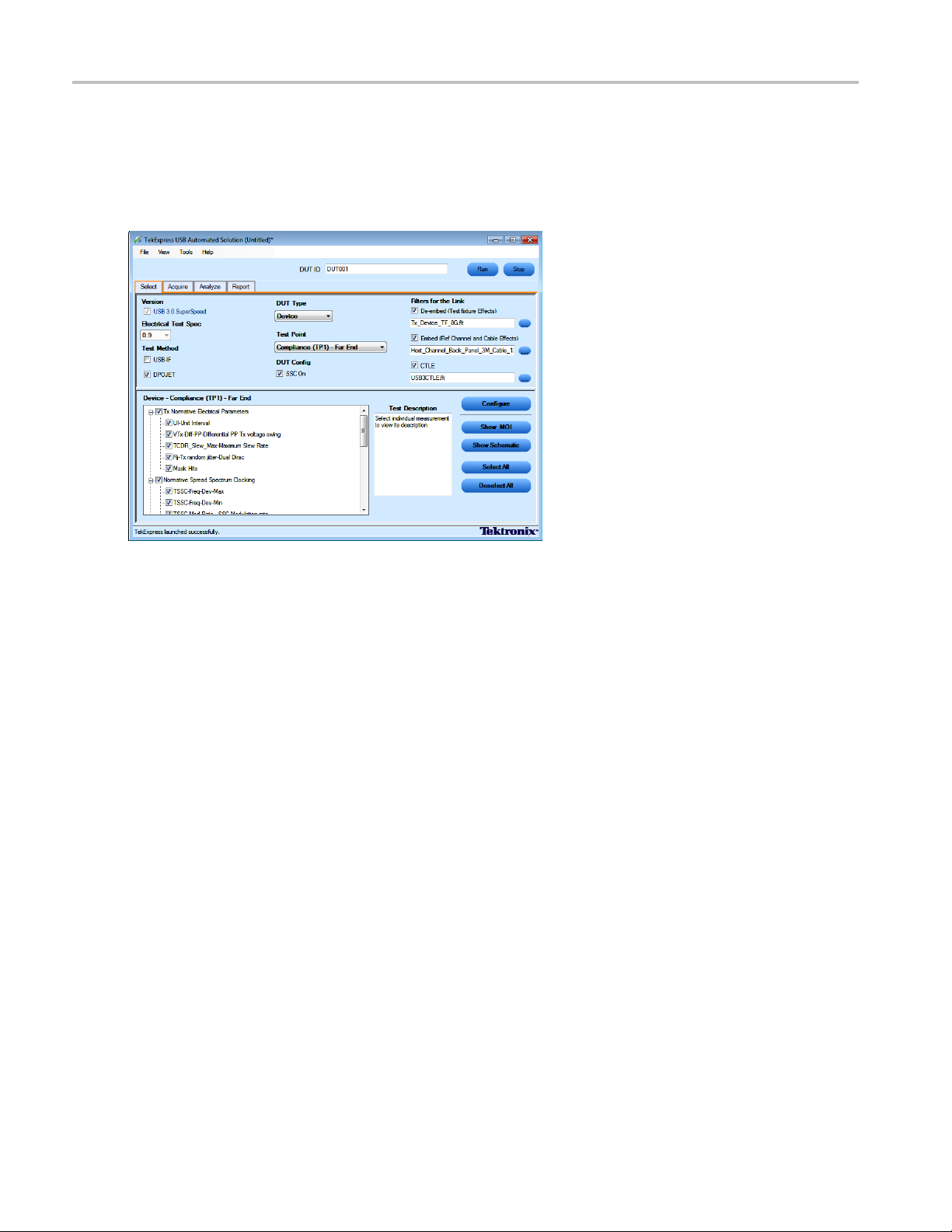
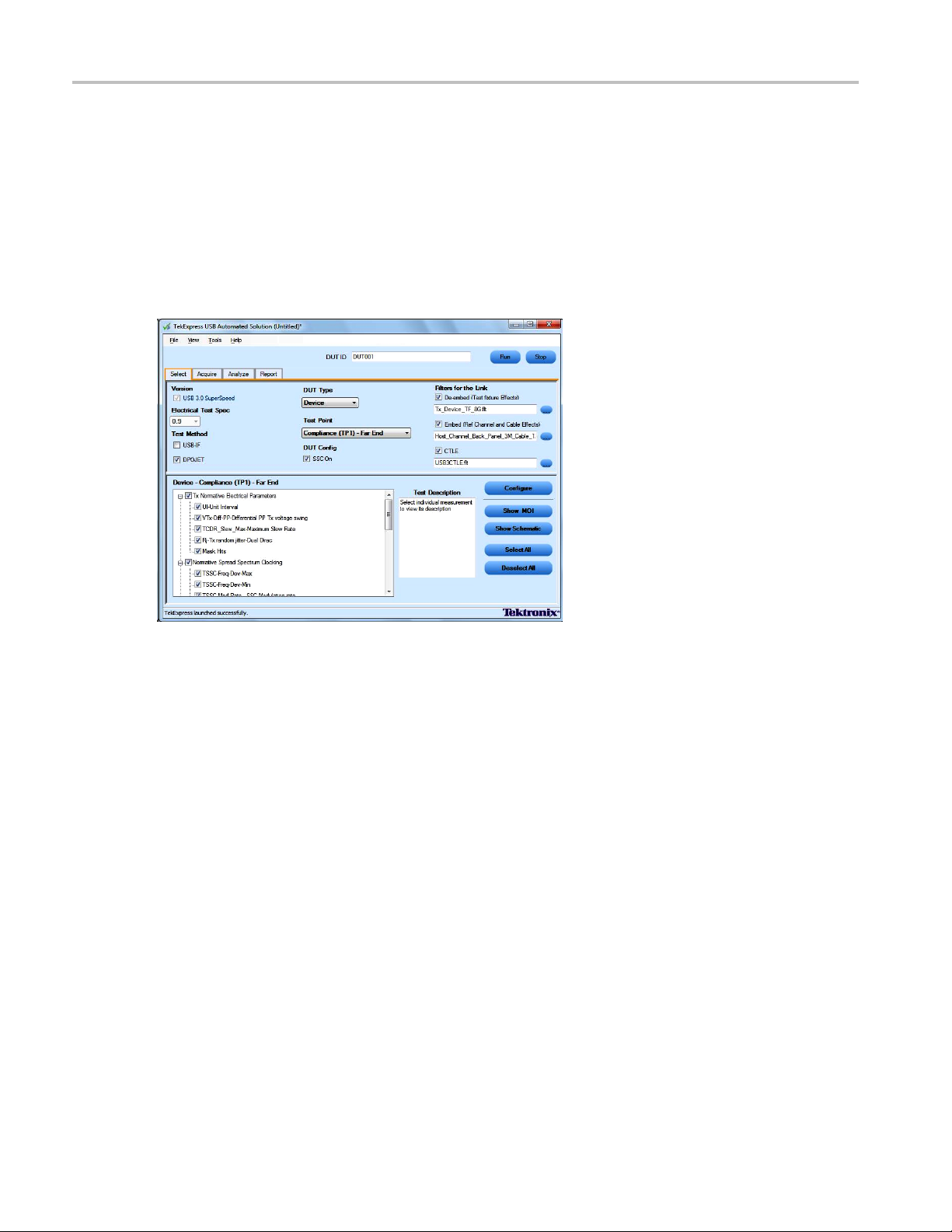
Select the Test(s)
TheSelectpanelletsyouselecttheUSBteststoconfigure and run.
This panel provides the following functions:
Version
USB 3.0 SuperSpeed is the default version selected.
Electrical Test Spe c
0.9 is the default value for electrical test specification.
Test Method
Select DPOJET or USB
option, a drop-down list appears showing the SigTest Tool software version installed on your computer.
-IF as appropriate for the measurement you want to run. If you select the USB-IF
Select DUT Type
Select the Device or Host of the device to test.
DUT Config
Select SSC tests based on your DUT configuration. If your DUT supports SSC, run the tests with 'SSC
on' selected.
26 TekExpress USB Automated Solutions Help
Page 37
How To Select the Test(s)
Test Point Selection
Select the appropriate test point location. For example, Compliance[TP1]-Far End, or TX Pin-Near End.
Only the compliance test point is available when SigTest is selected.
Filter for th
eLink
Enhanced filter file selection based on selected DUT Type and Test Point.
Measurements are grouped according to standard specifications such as Tx Informative Electrical
Parameters (see page 27), Normative Speed Spectrum Clocking (see page 27), Tx Normative Eye Mask
(see page 27)
,andLFPS measurement (see page 28).
Once you select a row, the following options are available:
Table 7: Button controls on the Select panel
Button Description
Opens the configuration panel for the selected test.
Opens the PDF file for the method of implementation (MOI) for the
selected test.
Opens the schematic for the selected test. This is useful to verify the
test setup before running the test.
Selects all tests in the table.
Deselects all tests in the table.
Indicates that the system has low hard disk memory space.
xxx
Tx Informative Electrical Parameters
Includes UI-Unit Interval, VTx-Diff-PP-Differential PP Tx voltage swing, TCDR_Slew_MaxMaximum Slew Rate, Rj-Tx-random jitter-Dual Dirac, and Mask Hits measurements.
Normative Speed Spectrum Clocking
Includes TSSC-Freq-Dev-Max, TSSC-Freq-Dev-Min, TSSC-Mod-Rate-SSC Modulation rate, and
TSSC USB Profile measurements.
Tx-Normative Eye Mask
Includes TJ-Tx total jitter-Dual Dirac at 10E-12 BER, DJ-Tx-deterministic Jitter-Dual Dirac, Eye
Height- Transmitter Eye Mask, and Width@BER measurements.
TekExpress USB Automated Solutions Help 27
Page 38
How To Configure and Run the Test(s)
LFPS Measurement
Includes LFPS Duty Cycle, LFPS Fall Time, LFPS Rise Time, LFPS TPeriod, LFPS TBurst,
LFPS TRepeat, LFPS Vcm-AC, and LFPS VTx-DIFF-PP mesurements.
See Also:
View and Select Connected Instruments (see page 31)
Configure and Run the Tests (see page 28)
View the Progress of Analysis (see page 34)
View the Report (see page 36)
View Test Related Files (see page 37)
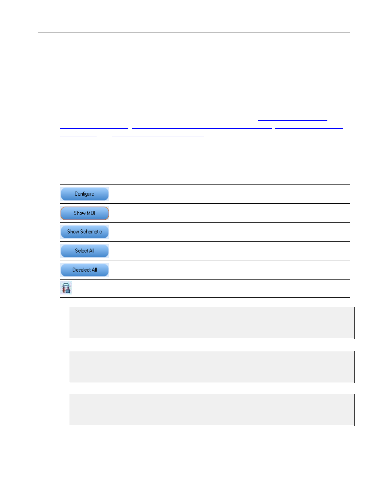
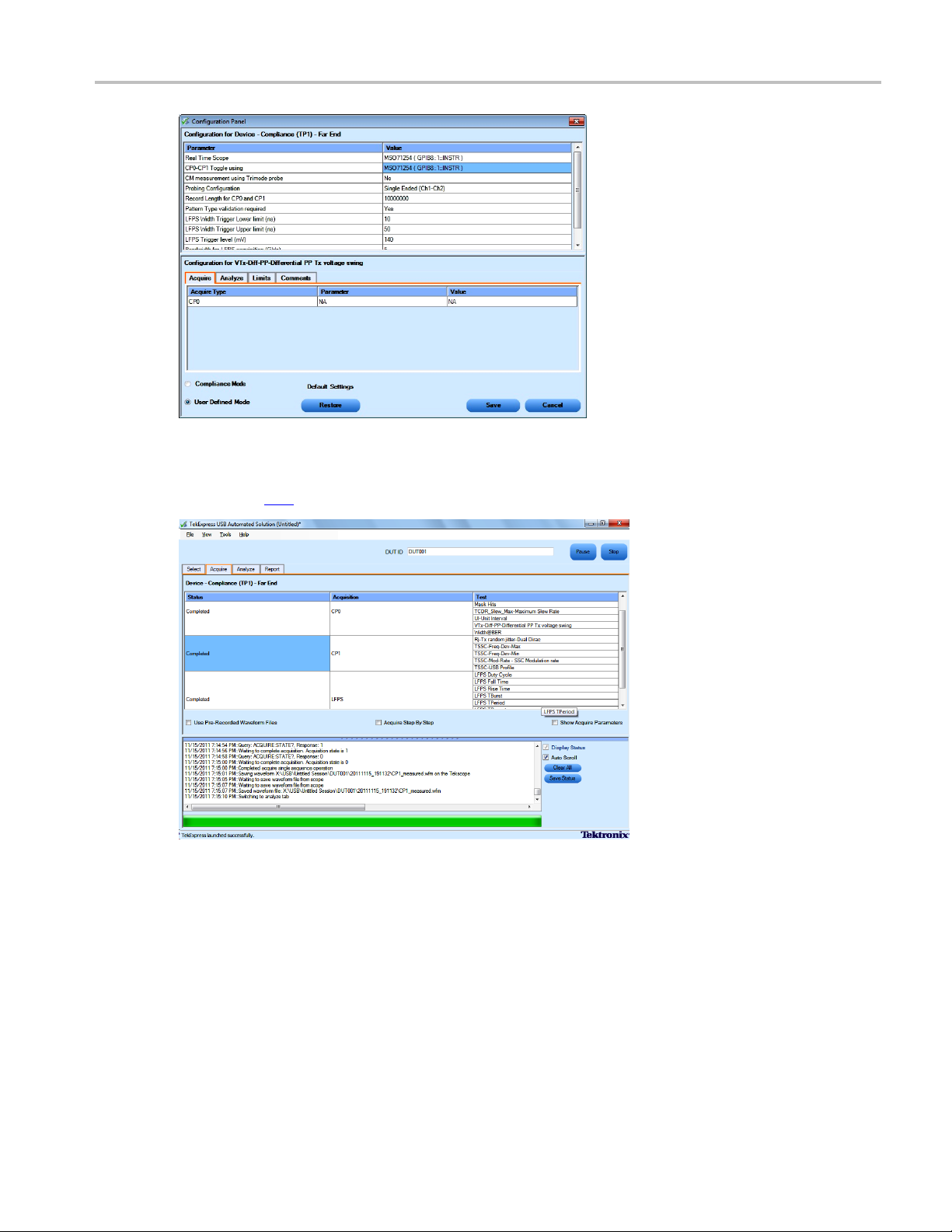
Configure and Run the Test(s)
The configuration panel controls let you create, view, and edit the parameters associated with the
acquisition and the analysis of the selected test. In the Select panel, click Configure.
The Configure panel lets you configure acquis
NOTE. Select different filter files under the Filter Selection option for different test suites.
The upper part of the Configure panel has ge
the selected test suite that are editable.
Select the appropriate instrumen
Select the Probing Configuration.
28 TekExpress USB Automated Solutions Help
t.
ition and analysis parameters.
neral parameters that are common for all the tests under
Page 39

How To Configure and Run the Test(s)
Select an appropriate parameter for “CP0–CP1 Toggle using” (AWG/AFG/Scope/Do Not Use).
Select to enable Pattern type validation. Selecting Yes enables the process of validating that each test
pattern is correct. Selecting No skips the test pattern validation.
The lower part of the Configure panel has test specific parameters.
NOTE. If any of the test parameters are grayed, it means that these parameters cannot be modified in the
compliance mode. When you switch to the user defined mode, these parameters are editable.
Table 8: Test parameters
Parameter
Acquire
Analyze
Limits
stoconfigure
Descripti
Shows the
related to acquisition of a selected
test. These parameters can vary
from one t
Shows the various parameters
related to analysis of a selected test.
The Analyze parameters shows the
default analysis parameters for the
selected test.
Refer to:
Using NonStandard Waveform
Mask
Applies to a specific test. It shows
the measurement limits using
different types of comparisons.
on
various parameters
est to another.
TekExpress USB Automated Solutions Help 29
Page 40

How To Configure and Run the Test(s)
Table 8: Test parameters (cont.)
Parameters to configure Description
Comments
Enter a descriptive comment up to
256 characters long for the selected
test.
Compliance settings
Restores the default settings.
Saves all changes made in the
Configuration Panel and closes the
box.
dialog
s the dialog box and without
Close
apply changes.
xxx
Click Run in the Select panel to run the selected tests.
Refer to the following table for different test limit comparisons:
Table 9: Different test limit comparisons
Comparison string Description
EQ(==)
NE(!=)
Equal to
Not equal to
GT(>) Greater than
LT(<)
Less than
GE(>=) Greater than or Equal to
LE(<=)
Less than or Equal to
GTLT(> <) Greater than and Less than
GELE(>= <=) Greater than or equal to and Less than or equal to
GELT(>= <) Greater than or equal to and Less than
GTLE(> <=) Greater than and Less or equal to
LTGT(< >) Less than and Greater than
LEGE(<= >=) Less than or equal to and Greater than or equal to
LEGT(<= >) Less than or equal to and Greater than
LTGE(< >=) Less than and Greater than or equal to
xxx
See Also:
View and Select Connected Instruments (see page 31)
30 TekExpress USB Automated Solutions Help
Page 41

How To View and Select Connected Instruments
Select the Tests (see page 26)
View the Progress of Analysis (see page 34)
t
View the Repo r
View Test Related Files (see page 37)
(see page 36)
View and Select Connected Instruments
Viewing Connected Instruments
The Tools > Instrument Bench menu item lets you discover connected instruments required for the tests.
The application uses TekVISA to discover the connected instruments. Once the search is finished, the
Instrument Bench dialog box resumes operation and lists the instrument-related details based on the
selected search criteria.
NOTE. When the TekVISA Instrument Manager checks for connected instruments, the Instrument Bench
dialog box does not respond.
For example, if you select LAN and GPIB as the search criteria in the Instrument Be nch dialog box and
click Refresh, the TekVISA Instrument Manager checks for the instruments available over LAN and GPIB
and the details of the instrument are displayed in the Retrieved Instruments table.
Use the TekVISA Timeout (Seconds) field, to set a time period within which if the TekVISA Instrument
Manager does not find the instruments, the TekExpress application resumes operation.
If you choose NonVISA resources, all the instruments supported by TekExpress but not communicating
over the VISA layer can be searched.
TekExpress USB Automated Solutions Help 31
Page 42

How To Use the Prerecorded Waveform for Analysis
Selecting Connected Instruments
Use the Configuration panel to view a list of connected instruments. The upper part of the panel displays
the general parameters for the tests under the se lected test suite.
NOTE. The list of instruments displayed is specific to the selected test suite. It does not show all the
connected instruments.
See Also:
Configure and Run the Tests (see page 28)
Select the Tests (see page 26)
View the Progress of Analysis (see page 34)
View the Report (see page 36)
View Test Related Files (see page 37)
Use the Prerecorded Waveform for Analysis
The Acquire tab shows unique acquisitions, acquisition parameters, acquisition status, and prerecorded
waveform files of the selected test suite. The Acquire panel is specific to a suite and is updated every time
the selected test suite is changed. This panel shows the acquisition details for the tests in the selected suite.
The tests with the common acquisition parameters are grouped together and shown as a single acquisition.
Column name Function
Status Test acquisition status of the running test passed at intervals.
Test
Name of the tests performing acquisitions. One or more tests can perform
the same acquisitions.
32 TekExpress USB Automated Solutions Help
Page 43

How To Use the Prerecorded Waveform for Analysis
Column name Function
Acquisition Acquisition name
Waveform File(s) Prerecorded waveform files of unique acquisitions. Select waveform files by
selecting bro
the standard file open window.
xxx
wse on individual cells. You can select any waveform file using
The following Acquire source options are available:
Use Pre-Recorded Waveform files: Toggles on or off the waveform file column in the acquisition
table. When you save a s ession and then select this option, the DUT ID text box changes to a
drop-down list, in which you can select the DUT ID up to the point where the session was saved. A
drop-down box appears above the Waveform file column, showing the run details, including the date
time of each run. If you select a run, corresponding data for that run will be populated (such as the
and
selected test, the test confi guration settings, and the test summary status).
TekExpress USB Automated Solutions Help 33
Page 44

How To View the Progress of Analysis
NOTE. To select the waveform files manually, select all the waveform (.wfm) files required for the
measurement. To select multiple files, hold down the Ctrl key to enable selecting multiple files in the File
Open dialog sc
Acquire Step by Step: Selecting this option prompts you at the end of each acquisition before
continuing t
Show Acquire Parameters: On enabling this option, the acquisition parameters for each unique
acquisitio
When you select “Use Pre-Recorded Waveform Files”, the first column shows the waveform type and the
second col
reen. If any required files are not selected, the measurement may not run properly.
o the next one.
n are displayed in the acquisition table.
umn shows the tests that use that waveform type for analysis.
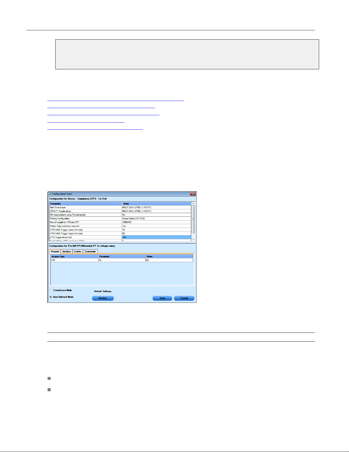
View the Progress of Analysis
Use the Analyze panel to view the progress of the analysis. As the analysis of each test is complete, the
result value is updated.
Analysis Table
The table contains the following:
The test name.
The status of the tests that are being run.
The measured, limit and margin values of the tests.
34 TekExpress USB Automated Solutions Help
Page 45

How To View the Progress of Analysis
The tests that are not yet started are shown with a “To be Started” status. The Status Messages panel
shows a summarized status of the running tests.
The Status Messages window timestamps all run time messages and displays them. You can do the
following:
Display Status: Enable/Disable status messages.
Auto Scroll: Scrolls status messages automatically.
Clear All: Clear all status messages in Status Window.
Save Status: Save all status messages in text file. Displays a standard save file window and saves the
status messages in the user specified file.
NOTE. You can resize and/or dock/undock the Status Messages window.
See Also:
Configure and Run the Tests (see page 28)
Select the Tests (see page 26)
View an
View the Repo rt (see page 36)
View Test Related Files (see page 37)
d Select Connected Instruments
(see page 31)
TekExpress USB Automated Solutions Help 35
Page 46

How To View the Report
View the Report
After the analysis, a report is automatically generated and displayed in the report panel. The report shows
the results of the tests, including device information and pass/fail status of each test. The following screen
is an example
The Report View Area contains an mht report. Select any area of the report and copy it to the clipboard to
make it avai
report of a test run using only DPOJET software.
lable to other applications.
See Also:
Select the Tests (see page 26)
Configure and Run the Tests (see page 28)
and Select Connected Instruments
View
View the Progress of Analysis (see page 34)
View Test Related Files (see page 37)
(see page 31)
36 TekExpress USB Automated Solutions Help
Page 47

How To View Test Related Files
View Test Related Files
All the test related files for selected tests are always saved at My Documents \My
TekExpress\USB\Untitled Session
.
When you save a session, it is saved with the session name to the path
TekExpress\USB\SessionName
The current session is stored in the same path as “Untitled Session” until you save it.
WARNING. Do not save a session file as “Untitled Session” or “Backup,” as these are application-specific
file names.
A session folder can contain results for more than one DUT, and a DUT folder can contain more than one
run data f
Here is an example image of data storage:
The application will delete these files when you exit the application.
older marked by date-time stamp as folder name.
for future references.
My Documents\My
See Also:
Select the Tests (see page 26)
Configure and Run the Tests (see page 28)
View and Select Connected Instruments (see page 31)
View the Progress of Analysis (see page 34)
Application Directories and Usage (see page 7)
Select and Run a Test Using SigTest Software (USB-IF)
Select and run a test using the USB-IF software. The steps are same as running a test using the DPOJET
software. See How To Select the Tests
1. Select Test Method USB-IF in the Select Panel. and browse to the latest version of USB-IF installed
on your machine.
TekExpress USB Automated Solutions Help 37
(see page 26).
Page 48

How To Select and Run a Test Using SigTest Software (USB-IF)
NOTE. The Test Method option is disabled if you have not installed USB-IF software (SigTest) on your
instrument or PC.
2. Click Run
the acquisition status.
3. The Analyze tab displays the Measured, High and Low limit values.
. While running, the application automatically switches to the Acquire tab and shows
38 TekExpress USB Automated Solutions Help
Page 49
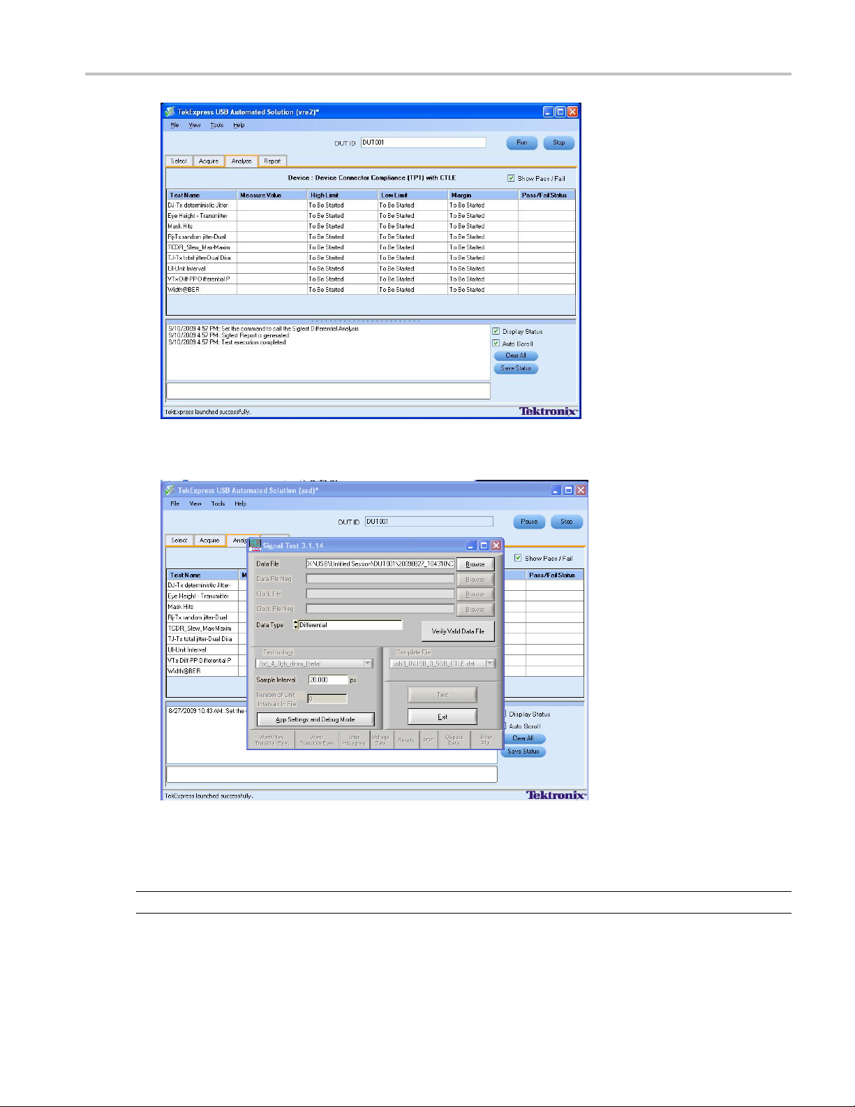
How To Select and Run a Test Using SigTest Software (USB-IF)
4. A SigTest dialog box appears to show that the application is using SigTest as the test method to
perform the analysis.
5. During test execution, once the analysis is completed, SigTest application automatically closes and
generates a report with the details. Click USB-IF Report linkontheTekExpressReporttabtoview
report location. Double-click the .html file to view the test report.
the
NOTE. Results shown in the TekExpress report tab are results from DPOJET.
TekExpress USB Automated Solutions Help 39
Page 50

How To Use Filters
Use Filters
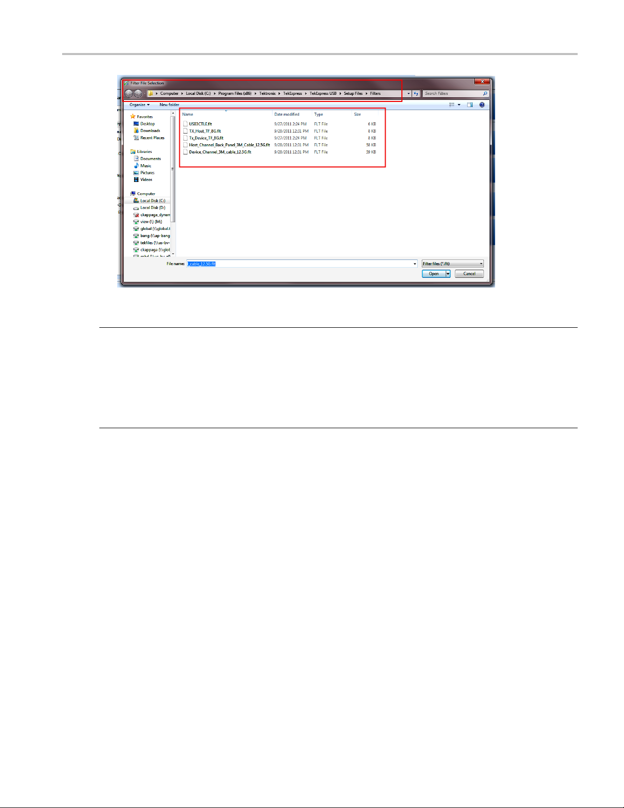
Using a N
Use the following procedure to select a nonstandard filter file.
1. Click the Select tab.
2. Click the Filters for the Link browse button to view the location of filter files from which to select.
onstandard Filter
40 TekExpress USB Automated Solutions Help
Page 51
How To Use Filters
3. Select a fil
e and click Open.
NOTE. The filter files are located in the TekExpress Filters folder.
For Micr
C:\Program Files (x86)\Tektroni x\TekExpress\TekExpress USB\Setupfiles\Filters
osoft Windows 7, the Filters folder file path is:
For Microsoft Windows XP or Windows XP Embedded, the Filters folder file path is:
C:\Program Files\Tektronix\TekExpress\TekExpress USB\Setupfiles\Filters
TekExpress USB Automated Solutions Help 41
Page 52
How To Use Filters
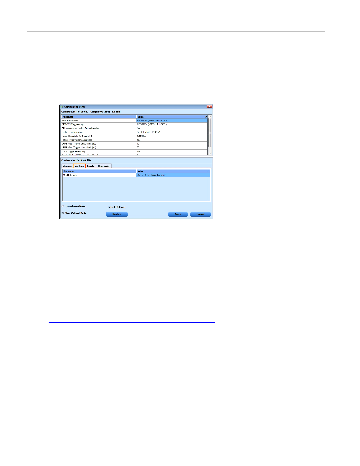
Using a Nonsta
To use a nonstandard mask file, follow this procedure:
1. Select the Mask Hits test in the Select panel and click Configure.
2. Click the Analyze tab in the Configure panel.
3. Enter the mask file name in the Analyze tab of the Configuration panel as shown. Click Save.
ndard Waveform Mask
NOTE. The mask files are located in the Te kExpress Masks folder.
For Microsoft Windows 7, the Masks folder file path is:
C:\Program Files (x86)\Tektronix\T ekExpress\TekExpress USB\Setupfiles\Masks
For Microsoft Windows XP or Windows XP Embedded, the Masks folder file path is:
rogram Files\Tektronix\TekExpress\TekExpress USB\Setupfiles\Masks
C:\P
See Also:
De-Embeding and Channel Embedding Overview (see page 87)
SDLA Filter Creation Requirements (see page 93)
42 TekExpress USB Automated Solutions Help
Page 53
How To LFPS Pattern Type Validation
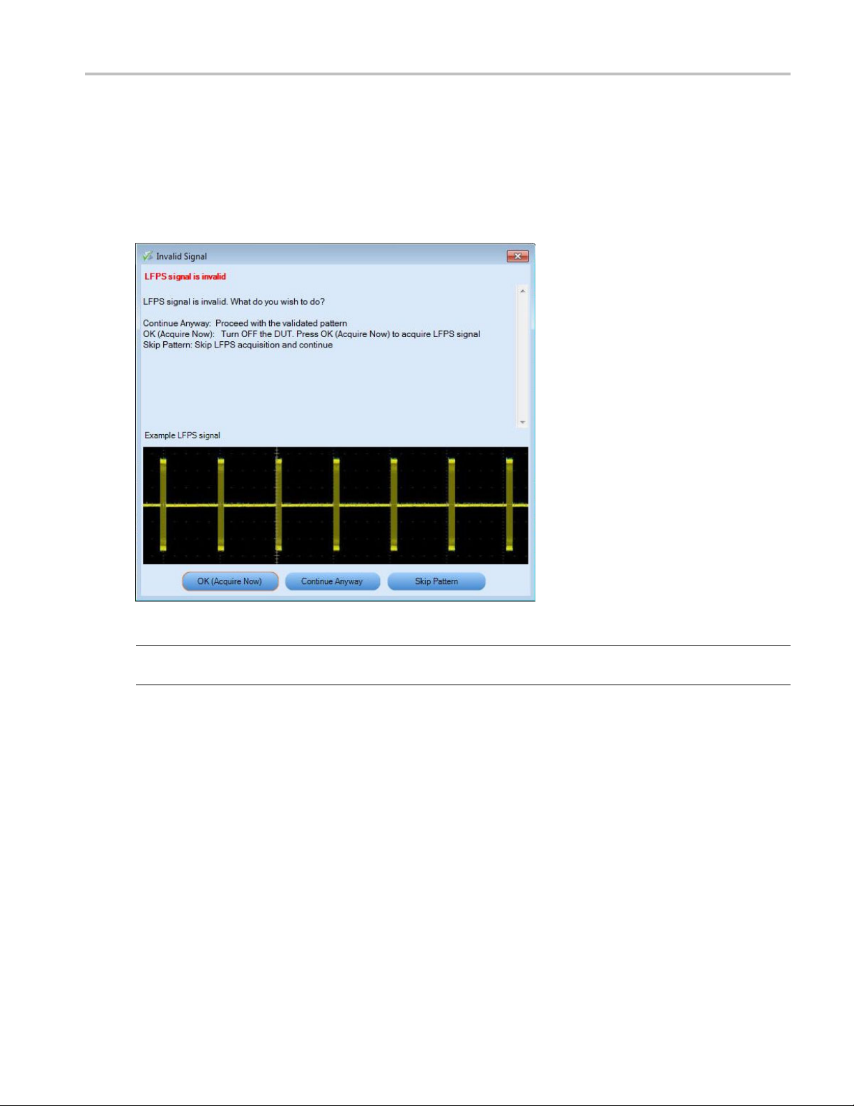
LFPS Pattern Type Validation
When the Pattern type validation is set to Yes, during the acquisition of LFPS pattern, a validation occurs.
If the pattern is valid, the measurement continues normally. If the pattern is invalid, the following pop
up displays.
NOTE. If Pattern type validation is selected as “No”, then the measurement continues with the acquired
orm.
wavef
Choose how to continue.
lect OK (Acquire now) to start the acquisition again.
■ Se
■ Select Continue Anyway to cause the measurements to continue with acquired waveform.
■ Select Skip Pattern to skip all LFPS tests. The rest of the selected measurements continue.
TekExpress USB Automated Solutions Help 43
Page 54
How To CP0 Pattern Type Validation
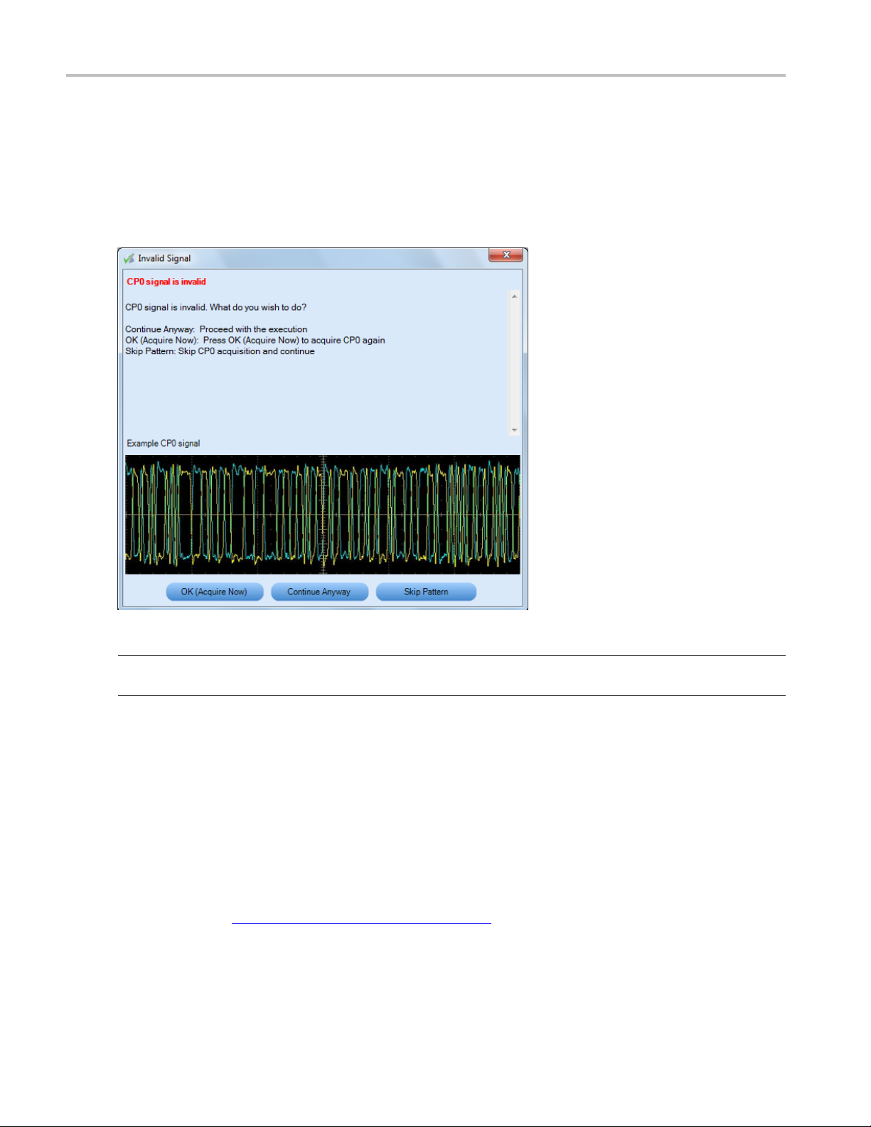
CP0 Pattern Type Validation
When the Pattern type validation is set to Yes, during the acquisition of a CP0 pattern, a validation occurs.
If the pattern is valid, the measurement continues normally. If the pattern is invalid, the following pop
up displays.
NOTE. If Pattern type validation is selected as “No”, then the measurement continues with the acquired
waveform.
Choose how to continue.
■ Select OK (Acquire now) to start the acquisition again.
lect Continue Anyway to cause the measurements to continue with acquired waveform.
■ Se
■ Select Skip Pattern to skip all CP0 tests. The rest of the selected measurements continue.
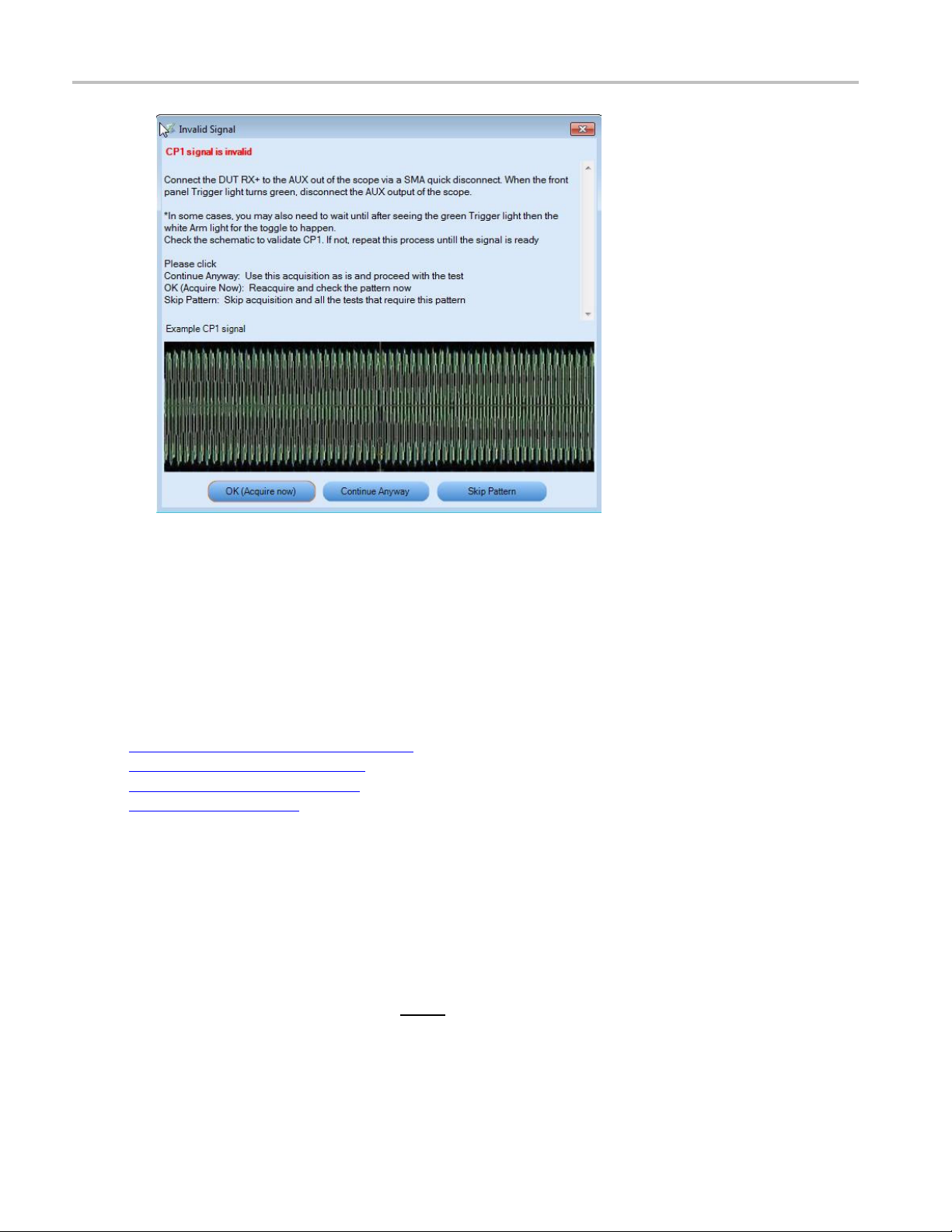
1 Pattern Type Validation
CP
efer to the topic Oscilloscope-Based Toggle
R
44 TekExpress USB Automated Solutions Help
(see page 45) and its related topics.
Page 55

How To Oscilloscope-Based Toggle
Oscilloscope-Based Toggle
To use the oscilloscope based toggle, follow this procedure.
NOTE. Oscilloscope based toggle is not guaranteed to work for all DUTs.
1. In the configuration panel, for the parameter CP0-CP1 Toggle using, select an oscilloscope (For
example DPO72004 (TCPIP::192.158.96.152::INSTR)).
2. Connect the AUX OUT from the oscilloscope to the USB 3.0 Device Fixture 2 RX+ and connect a
USB cable from USB 3.0 Device Fixture 2 to Device fixture 1.
3. Click the Run button. If the CP1 measurements are selected, then when the CP1 pattern is being
acquired, a pop up displays to prompt you to make the necessary connections. Select to either s kip the
pattern o
r make a new acquisition after the DUT is transmitting CP1.
4. If you click OK (Acquire Now), the application does a new acquisition. If Pattern Type validation is
set to Yes, a Pattern Type validation is done on the acquired signal to check if it is a CP1 signal. If
is a CP1 signal, the measurements continue normally. If not, the application shows the following
it
dialog box.
NOTE. If Pattern type validation is set to No, then the measurement continues with the acquired waveform.
TekExpress USB Automated Solutions Help 45
Page 56
How To AWG-Based Toggle
5. Choose how to continue:
■ Select OK (Acquire now) to start the acquisition again.
■ Select Continue Anyway to cause the measurements to continue with acquired waveform.
■ Select Skip Pattern to skip all CP1 tests. The rest of the selected measurements are taken. If CP1 is
skipped and CP0 is aquired, TJ and RJ are computed on CP0 for informational purposes.
See Also:
Oscilloscope-Based Toggle (see page 45)
AWG-Based Toggle (see page 46)
AFG-Based Toggle (see page 48)
ggle
No To
(see page 49)
AWG-Based Toggle
To use the arbitrary waveform generator (AWG) based toggle, follow this procedure.
1. In the configuration panel, for the parameter CP0-CP1 Toggle using, select an AWG (For example
AWG7122C (TCPIP::192.158.96.152::INSTR)).
2. Connect the interleave (analog and analog
2 (RX+ and RX-) and connect a USB cable from the USB 3.0 Device Fixture 2 to USB 3.0 Device
fixture 1.
46 TekExpress USB Automated Solutions Help
) output of Ch1 of the AWG to the USB 3.0 Device Fixture
Page 57
How To AWG-Based Toggle
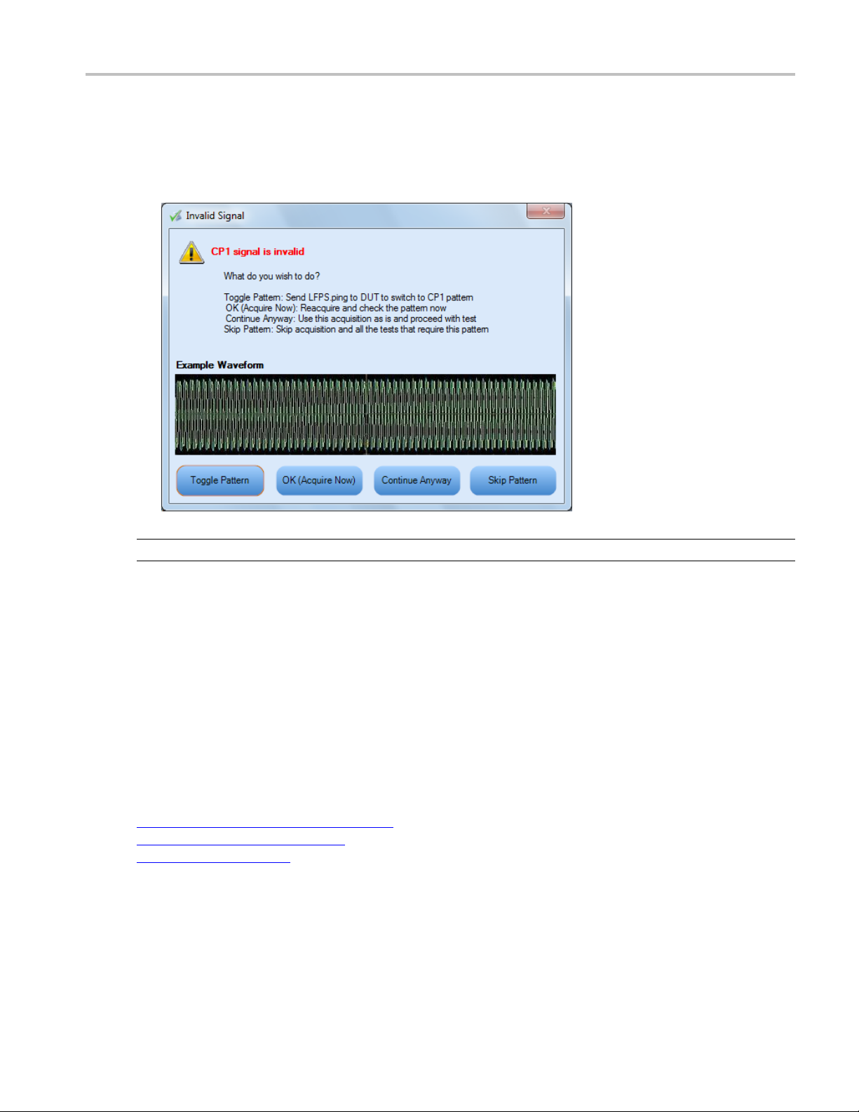
3. Click the Run button. If the CP1 measurements are selected, then when the CP1 pattern is being
acquired, a command is sent to the AWG to send a trigger to toggle the DUT from CP0 to CP1.
Next, the wave
If the pattern is valid, the measurement continues normally. If the pattern is not valid, the following
popupdisplays.
form is acquired. If Pattern type validation is set to Yes, then the validation occurs.
NOTE. If Pattern type validation is set to No, then the measurement continues with the acquired waveform.
4. If you select Toggle Pattern, then the toggle sequence is initiated again to toggle the DUT. (The
pop up remains displayed during this toggle process.) You can visually verify whether the acquired
pattern is correct. If not, keep clicking the Toggle Pattern button until the correct pattern is acquired.
Once you acquire the correct pattern, click OK (Acquire Now) to save the waveform and continue
with the measurement.
5. At any time, you can select Continue Anyway to continue with the current acquired waveform.
You can also select Skip pattern to skip the CP1 acquisition and continue with the rest of selected
surements.
mea
See Also:
Oscilloscope-Based Toggle (see page 45)
AFG-Based Toggle (see page 48)
No Toggle (see page 49)
TekExpress USB Automated Solutions Help 47
Page 58

How To AFG-Based Toggle
AFG-Based Toggle
To use the arbitrary function generator (AFG) based toggle, follow this proce dure.
1. In the configuration panel, select an AFG instrument for the parameter CP0-CP1 Toggle (For example:
AFG3102 (TCPIP::192.158.96.152::INSTR)).
2. Connect Ch1 of the AFG to the D evice fixture 2 (RX+).
3. Connect a 3 meter USB cable from Device fixture 2 to Device fixture 1.
4. Click the Run button. If the C P1 measurements are selected, a command is sent to AFG, when the
CP1 pattern is being acquired, to toggle the DUT from CP0 to CP1. Next, the pattern is acquired. If
Pattern type validation is set to Yes, then the validation occurs. If the pattern is valid, the measurement
continues normally. If the pattern is not valid, the application opens the following dialog box.
NOTE. If Pattern type validation is set to No, then the measurement continues with the acquired waveform.
5. If you click Toggle Pattern, then the toggle sequence is initiated again to toggle the DUT. (The dialog
box remains displayed during this toggle process.) You can visually verify whether the acquired
pattern is correct. If the pattern is not correct, continue clicking the Toggle Pattern button until you
quire the correct pattern. Once the correct pattern is acquired, click OK (Acquire now) to save the
ac
waveform and continue with the measurement.
t any time, you can click Continue Anyway at any time to continue with the current acquired
6.A
waveform. You can also click Skip Pattern to skip the CP1 acquisition and continue with rest
of selected measurements.
48 TekExpress USB Automated Solutions Help
Page 59

How To No Toggle
User-Configurable AFG Parameters
You can configure the following parameters in the Configuration panel before the start of Test Execution
when AFG is set as the toggle tool:
AFG Voltage Level High (V): The range is from –5 V to 5 V. The default value is 0.5 V.
AFG Voltage Level Low (V): The range is from –5 V to 5 V. The default value is –0.5 V.
AFG Frequency (MHz) : The range is from 10 MHz to 100 MHz. The default value is 20 MHz.
AFG Nu
See Also:
Oscilloscope-Based Toggle (see page 45)
AWG-Based Toggle (see page 46)
No Toggle (see page 49)
No Toggle
To not use the toggle tool, follow this procedure.
1. In the confi guration panel, for the parameter CP0-CP1 Toggle using, set to Do not use.
m of Cycles per Second:Therangeisfrom1to5.Thedefaultvalueis2.
he following pop up is displayed just before acquiring the CP0/CP1 pattern to allow you to manually
2.T
transmit the desired pattern and acquire the waveform.
TekExpress USB Automated Solutions Help 49
Page 60

How To No Toggle
3. Click OK to acquire the waveform. If Pattern type validation is set to Yes, a pattern type validation
occurs on the acquired signal. If it is a valid pattern, the measurement continues normally.
If it is not a valid CP1 pattern, the following pop up displays.
If it is not a valid CP0 pattern, the following pop up displays.
50 TekExpress USB Automated Solutions Help
Page 61

How To No Toggle
NOTE. If Pattern type validation is set to No, then the measurement continues with the acquired waveform.
4. Choose
■ Select OK (Acquire now) to start the acquisition again.
■ Select Continue Anyway to cause the measurements to continue with acquired waveform.
■ Select Skip Pattern to skip all CP0-CP1 tests. The rest of the selected measurements continue.
how to continue.
See Also:
Oscilloscope-Based Toggle (see page 45)
AWG-Based Toggle (see page 46)
-Based Toggle
AFG
(see page 48)
TekExpress USB Automated Solutions Help 51
Page 62

How To No Toggle
52 TekExpress USB Automated Solutions Help
Page 63

Application Examples Testing a Device Transmitter Using USB-IF Software
Testing a Device Transmitter Using USB-IF Software
The following procedure describes how to use the USB-IF test method to test a device with a hardware
channel. For the required equipment and setup diagram click here
.
NOTE. USB com
Definition is set to Software mode. When Hardware mode is selected, the same testing is performed
with a physical channel.
1. Select Device as the DUT type.
2. Select US
3. Unselect the DPOJET test method if selected.
pliance testing is done by using software to emulate the channel and cable when Channel
B-IF test method.
4. Click Configure to configure the test parameters. Note that the C onfigure panel will be Compliance
only.
Mode
5. You can configure any test to help you analyze measurement results. To refer to the DPOJET
erSpeed (USB 3.0) Setup Library Methods of Implementation (MOI) document for information on
Sup
how to configure the Deterministic Jitter test, click Show MOI in the Select panel.
ick Close to close the dialog box.
6. Cl
TekExpress USB Automated Solutions Help 53
Page 64

Application Examples Testing a Device Transmitter Using USB-IF Software
7. Click Run in the Select panel to run the selected test.
8. The Acquire panel shows the status of the waveform acquisition. To know more about the Acquire
panel, click here
.
9. The Analyze tab displays the Measured, High and Low limit values and a SigTest tool pop-up appears.
The Analyze tab shows the DPOJET results, not the SigTest re sults.
NOTE. F
related topics.
or toggling from CP0 to CP1, refer to topic Oscilloscope-Based Toggle
(see page 45) and its
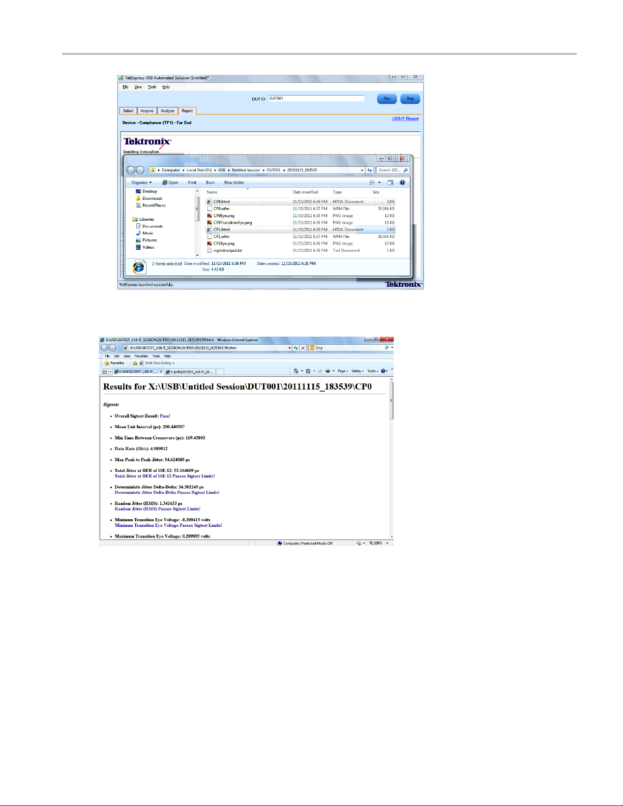
o open the USB-IF report location, click the USB-IF Report linkontheReporttabtoviewthe
10.T
report location.
54 TekExpress USB Automated Solutions Help
Page 65
Application Examples Testing a Device Transmitter Using USB-IF Software
11. Double-click the .html file to view the test report. The following graphics show reports for CP0 and
CP1 tests.
TekExpress USB Automated Solutions Help 55
Page 66

Application Examples Testing a Device Transmitter Using USB-IF Software
56 TekExpress USB Automated Solutions Help
Page 67

Application Examples Set Up the Equipment
Set Up the Equipment
You need the following equipment:
Table 10: Required equipment
Resource Model supported
Real-time os cil loscope
Probes
Test F ixtu r e
AWG/AFG (optional) AWG7102 (v3.3), AWG7122 Series (v4.1.1.5), with options 6,8.
xxx
1
Available through USB-IF.
Connect the equipment as shown in the following diagram:
NOTE. The VBUS on the device fixture is typically powered from an external power supply, not from
the AWG.
Tektronix MSO/DPO/DSA71254 Series. Also MSO/DPO/DSA70804 Series
is suitable for Normative measurements.
A minimum of 12 GHz bandwidth is required for compliance testing.
Two TCS-SMA or one P7300SMA/P7500 differential probe.
TF-USB3-KIT (includes short USB 3.0 cable) or USB-IF fixtures
1
.
AFG3252, AFG3251, AFG3102, AFG3101.
TekExpress USB Automated Solutions Help 57
Page 68
Application Examples Testing a Device Transmitter
Testing a Device Transmitter
The following procedure describes how to use TekExpress to test the Device back panel.
1. Select Device as the DUT type.
2. Select Compliance (TP1) - Far End as the test point.
3. Select all tests.
4. Click Configure to set the test parameters.
5. You can configure any test to help you analyze measurement results. Refer to the DPOJET SuperSpeed
(USB 3.0) Setup Library Methods of Implementation (MOI) document for information on how to
configure the Deterministic Jitter test (click Show MOI in the Select panel).
6. Once you change the parameters, click Apply to apply the new settings for the selected test. To
restore the default settings, click Restore.
Click Close to close the dialog box.
58 TekExpress USB Automated Solutions Help
Page 69
Application Examples Testing a Device Transmitter
7. Click Run i
8. The Acquire panel shows the status of the waveform acquisition. To know more about the Acquire
panel, cl
9. The Analyze tab displays the Measured, High, and Low limit values.
n the Select panel to run the selected tests.
ick here
.
TekExpress USB Automated Solutions Help 59
Page 70

Application Examples Testing a Device Transmitter
10. After the tests complete, a report is generated and displayed in the Report panel.
NOTE. For toggling from CP0 to CP1, refer to topic Oscilloscope-Based Toggle
related topics.
(see page 45) and its
You can save the report using the File > Save Report As option. The following dialog box is displayed.
60 TekExpress USB Automated Solutions Help
Page 71

Application Examples Testing a Device Transmitter
If CP1 is skipped, then the measurements RJ and TJ are done on CP0 for information only.
TekExpress USB Automated Solutions Help 61
Page 72

Application Examples Testing a Device Transmitter
62 TekExpress USB Automated Solutions Help
Page 73

TekExpress Programmatic Interface About the Programmatic Interface
About the Programmatic Interface
The Programmatic interface lets you seamlessly integrate the TekExpress test automation application with
the high-level automation layer. This also lets you control the state of TekExpress application running on a
local or a rem
(see page 72) Query DUT ID
(see page 73) Set DUT ID
(see page 74) SaveSession
(see page 76) RecallSession
(see page 77) Run the TekExpress execution
ote PC. Use the TekExpress programmatic interface to do the following operations:
(see page
(see page 80) Transfer result files
(see page 81) Check the application status
NOTE. The programmatic interface is not available for the following pop-up screens:
Scope as Toggle Tool (User Action Required, two button pop-up for CP1)
AWG as Toggle Tool (Invalid Signal, four button pop-up)
AWG as Toggle Tool (Invalid Signal, four button pop-up)
For simplifying the descriptions, the following terminologies are used in this section:
Tek
TekExpress Programmatic Interface.
kExpress Server: The TekExpress application when being controlled by TekExpress Client.
Te
TekExpress leverages .Net Marshalling to enable the Programmatic Interface for TekExpress Client.
TekExpress provides a client library for TekExpress clients to use the programmatic interface. The
TekExpress client library is inherited from .Net MarshalByRef class to provide the proxy object for the
78) Stop the TekExpress execution
Express Client: A high level automation application that communicates with TekExpress using
TekExpress USB Automated Solutions Help 63
Page 74

TekExpress Programmatic Interface About the Programmatic Interface
clients. The TekExpress client library maintains a reference to the TekExpress Server and this reference
allows the client to control the server state.
Click the following links to get details on them:
What is needed to develop a TekExpress Client ?
You need to use the TekExpressClient.dll to develop a TekExpress Client. The client can be a VB .Net, C#
.Net, TestStand, or a web application. The examples for interfaces in each of these applications are in
Samples folder.
References Required
TekExpressClient.dll has internal reference to IIdlglib.dll and IRemoteInterface.dll IIdlglib.dll has a
reference to TekDotNetLib.dll. IRemoteInterface.dll provides the interfaces required to perform the remote
automations. It is an interface that forms the communication line between the server and the client.
IIdlglib.dll provides the methods to generate and direct the secondary dialog messages at the client-end.
NOTE. The end-user client application does not need any reference to above mentioned DLL files. It is
essential to have these DLLs (IRemoteInterface.dll, IIdlglib.dll and TekDotNetLib.dll) in same folder
location as that of TekExpressClient.dll.
What steps does a client need to follow ?
Use the following information to use the TekExpressClient.dll to programmatically control the server:
A client UI has to be developed to access the interfaces exposed through the server. This client must load
TekExpressClient.dll to access the interfaces. Once the TekExpressClient.dll is loaded, the client
UI can call the specific functions to run the operations requested by the client. Once the client is up and
running, it has to do the following to run a remote operation:
1. The client must provide the IP address of the PC at which the server is running so that it can connect to
the server.
2. The client must lock the server application to avoid conflict with any other Client that may try to
control the server simultaneously. “Lock” would also disable all user controls on server so that server
state cannot be changed by manual operation.
64 TekExpress USB Automated Solutions Help
Page 75

TekExpress Programmatic Interface Server and Client Proxy Objects
3. If any other client tries to access a server which is locked, it will get a message that the server
is locked by another client.
4. When the client has connected to and locked the server, the client can access any of the programmatic
controls to run the remote automations.
5. Once the client operations are completed, the server must be “unlocked” by the client.
See Also:
Server and Client Proxy Objects (see page 65)
Server and C lient Proxy Objects
Remote P
The server exposes a remote object to let the remote client access and perform the server side operations
remote
The following is an example:
RemotingConfiguration.RegisterWellKnownServiceType (typeof (TekExpressRemoteInterface), “TekExpress Remote interface”, WellKnownObjectMode.Singleton);
This object lets the remote client access the interfaces exposed at the server side. The client gets the
reference to this object when the client gets connected to the server.
roxy Object
ly. The proxy object is instantiated and exposed at the server-end through marshalling.
For example,
//Get a reference to the remote object
remoteObject = (IRemoteInterface)Activator.GetObject(typeof(IRemoteInterface),
URL.ToString());
TekExpress USB Automated Solutions Help 65
Page 76

TekExpress Programmatic Interface Server and Client Proxy Objects
Client Proxy O
Client exposes a proxy object to receive certain information.
For examp
//Register the client proxy object
WellKnownServiceTypeEntry[] e = RemotingConfiguration.GetRegisteredWellKnownServiceTypes();
clientInterface = new ClientInterface();
RemotingConfiguration.RegisterWellKnownServiceType(typeof(ClientInterface),
“Remote Client Interface”, WellKnownObjectMode.Singleton);
bject
le,
//Expose the client proxy object through marshalling
RemotingServices.Marshal(clientInterface, "Remote Client Interface");
The client proxy object is used for the following:
1. To g
et the secondary dialog messages from the server.
2. To get the file transfer commands from the server while transferring the report.
Click here to see examples.
clientObject.clientIntf.DisplayDialog(caption, msg,iconType, btnType);
clientObject.clientIntf.TransferBytes(buffer, read, fileLength);
66 TekExpress USB Automated Solutions Help
Page 77

TekExpress Programmatic Interface Connect()
To know more on the topics below, click the links.
Secondary Dialog Message Handling
The secondary dialog messages from the Secondary Dialog library are redirected to the client-end when a
client is performing the automations at the remote end.
In the secondary dialog library, the assembly that is calling for the dialog box to be displayed is checked
and if a remote connection is detected, the messages are directed to the remote end.
File Transfer Events
When the client requests the transfer of the report, the server reads the report and transfers the file by
calling the file transfer methods at the client-end.
Conne
Connect(string ipAddress, IRemoteClientIn terface clientIntf, out string clientID)
This method connects the client to the server. The client provides the ip address of the server to connect to
the server. The server provides a unique clientId when the client is connected to it.
ct()
TekExpress USB Automated Solutions Help 67
Page 78

TekExpress Programmatic Interface Connect()
Parameters
Name Type Direction Description
ipAddress
clientIntf String
clientid
xxx
String
String OUT Identifier o
IN
IN
The ip address of the server to which the client is
trying to connect to. This is required to establish
the connectio
Is the handle
server.
clientId = unique number + ipaddress of the
client. For
n between the server and the client.
of the remote object interface
f the client that is connected to the
example, 1065–192.157.98.70
Return Value
Value that suggests the status if the connection was established or an error occurred. The return value can
be a boolean value (true), or a string (returning the error message).
Example
try {
IPAddress[] hostIPAddr = Dns.GetHostAddresses(Dns.GetHostName());
// Connect to the remoter Server
remoteObject.Connect(hostIPAddress, clientInterface, out clientID);
return true;
}
ch (Exception error)
cat
{
return error;
}
Comments
The server has to be active and running for the client to connect to the server. Any number of clients can
be connected to the server at a time. Each client will get a unique id.
68 TekExpress USB Automated Solutions Help
Page 79

TekExpress Programmatic Interface Disconnect()
Disconnect()
Disconnect(s
tring id)
This method disconnects the client from the server it is connected to.
Parameters
Name Type Direction Description
id
xxx
Return Va
String
lue
IN
Identifier of the client that is performing
the remote function.
Integer value that indicates the status of the operation upon completion.
1: Success
–1: Failure
Example
try
{
string returnVal = UnlockServer (c lientId);
remoteObject.Disconnect (clientId);
urn 1;
ret
}
Comments
en the client is disconnected, it is unlocked from the server and then disconnected. The id is reused.
Wh
TekExpress USB Automated Solutions Help 69
Page 80

TekExpress Programmatic Interface LockSession()
LockSession()
LockSession(
string id)
This method locks the server. The client has to call this method before running any of the remote
automations
. The server is locked by only one client.
Parameters
Name Type Direction Descriptio
id
xxx
String
IN
Identifier
the remote function.
n
of the client that is performing
Return Value
String v
alue that indicates the status of the operation upon completion.
Example
if (locked)
n “Session has a lready been locked!”;
retur
returnVal = remoteObject.LockSession(clientId);
if ((OP_STATUS)returnVal == OP_STATUS.SUCCESS)
{
locked = true;
return “Session Locked...”;
}
Comments
When the client tries to lock a server that is locked by another client, the client gets a message that the
server is already locked and it has to wait until the server is unlocked.
Iftheclientlockstheserverandisidleforacertain amount of time then the server is unlocked
automatically from that client.
70 TekExpress USB Automated Solutions Help
Page 81

TekExpress Programmatic Interface UnlockSession()
UnlockSession()
UnlockSessio
n(string id)
This method unlocks the server from the client. The client id of the client to be unlocked has to be provided.
Parameters
Name Type Direction Description
id string IN
xxx
Return Va
lue
Identifier of the client that is performing
the remote function.
String that indicates the status of the operation upon completion.
Example
return
if ((OP_STATUS)returnVal == OP_STATUS.SUCCESS)
{
Val = remoteObject.UnlockSession(clientId);
locked = false;
return “Session UnLocked...”;
}
Comments
When the client is disconnected, it is automatically unlocked.
TekExpress USB Automated Solutions Help 71
Page 82

TekExpress Programmatic Interface GetDutId()
GetDutId()
GetDutId(str
ing id, string dutId)
This method gives the DUT id of the current set-up.
Parameters
Name Type Direction Description
id string IN
dutId string
xxx
Return Va
lue
OUT The DUT id of the set-up.
Identifier of the client that is performing
the remote function.
String that gives the timeout period (in seconds) of the client.
Example
return
if ((OP_STATUS)returnVal == OP_STATUS.SUCCESS)
{
Val = remoteObject.GetDutId(clientId, out id);
return id;
}
else
urn CommandFailed(returnVal);
ret
Comments
The dutId is an OUT parameter whose value is set after the server processes the request.
72 TekExpress USB Automated Solutions Help
Page 83

TekExpress Programmatic Interface ChangeDutId()
ChangeDutId()
ChangeDutId(
string id, string dutName)
This method changes the DUT id of the set-up. The client has to provide a valid DUT id.
Parameters
Name Type Direction Description
id string IN
dutName string IN
xxx
Return Va
lue
Identifier of the c lient that is performing
the remote function.
The new DUT id of the set-up.
String that indicates the status of the operation upon completion.
Example
If (dut
return “Enter a valid DUT-ID”;
returnVal = remoteObject.ChangeDutId(clientId, dutId);
Id.Length <=0 && locked == true)
if ((OP_STATUS)returnVal == OP_STATUS.SUCCESS)
return “DUT Id Changed...”;
else
urn CommandFailed(returnVal);
ret
Comments
If the dutName parameter is null, the client is prompted to provide a valid DUT id.
TekExpress USB Automated Solutions Help 73
Page 84

TekExpress Programmatic Interface SaveSession()
SaveSession()
SaveSession(
string id, string name)
Saves the current session. The name of the session is provided by the client.
Parameters
Name Type Direction Description
id string IN
name
xxx
Return Va
lue
string IN
Identifier of the client that is performing
the remote function.
The name of the session being saved.
String that indicates the status of the operation upon completion.
Example
return
if ((OP_STATUS)returnVal == OP_STATUS.SUCCESS)
Val = remoteObject.SaveSession(clientId,sessionName);
return “Session Saved...”;
else
return CommandFailed(returnVal);
Comments
The name parameter cannot be empty. If it is empty, the client is prompted to provide a valid name.
Once the session is saved under ‘name,’ you cannot use this method to save the session with a different
name. Use SaveSessionAs to save the session to a new name.
74 TekExpress USB Automated Solutions Help
Page 85

TekExpress Programmatic Interface SaveSessionAs()
SaveSessionAs()
SaveSessionA
s(string id, string name)
Saves the current session in a different name every time this method is called. The name of the session is
provided by t
he client.
Parameters
Name Type Direction Descriptio
id string IN
name
xxx
string IN
Identifier
the remote function.
The name of the session being saved.
n
of the client that is performing
Return Value
String t
hat indicates the status of the operation upon completion.
Example
returnVal = remoteObject.SaveSessionAs(clientId,sessionName);
if ((O
P_STATUS)returnVal == OP_STATUS.SUCCESS)
return “Session Saved...”;
else
return CommandFailed(returnVal);
Comments
The same session is saved under different names using this method. The name parameter cannot be empty.
If it is empty, the client is prompted to provide a valid name.
TekExpress USB Automated Solutions Help 75
Page 86

TekExpress Programmatic Interface RecallSession()
RecallSession()
RecallSessio
n(string id, string name)
Recalls a saved session. The name of the session is provided by the client.
Parameters
Name Type Direction Description
id string IN
name
xxx
Return Va
lue
string IN
Identifier of the client that is performing
the remote function.
The name of the session being recalled.
String that indicates the status of the operation upon completion.
Example
return
if ((OP_STATUS)returnVal == OP_STATUS.SUCCESS)
Val = remoteObject.RecallSession(clientId,sessionName);
return “Session Recalled...”;
else
return CommandFailed(returnVal);
Comments
The name parameter cannot be empty. If it is empty, the client is prompted to provide a valid name.
76 TekExpress USB Automated Solutions Help
Page 87

TekExpress Programmatic Interface Run()
Run()
Run(string id
)
Runs the setup. Once the server is set up and configured, it can be run remotely using this function.
Parameters
Name Type Direction Description
id string IN
xxx
Return Va
lue
Identifier of the client that is performing
the remote function.
String that returns the status of the operation after completion.
Example
return
if ((OP_STATUS)returnVal == OP_STATUS.SUCCESS)
else
Val = remoteObject.Run(clientId);
return “Run started...”;
return CommandFailed(returnVal);
Comments
When the run is performed the status of the run is updated periodically using a timer.
TekExpress USB Automated Solutions Help 77
Page 88

TekExpress Programmatic Interface Stop()
Stop()
Stop(string i
d)
Stops the run operation.
Parameters
Name Type Direction Description
id string IN
xxx
Return Va
lue
Identifier of the client that is performing
the remote function.
String that indicates the status of the operation upon completion.
Example
return
if ((OP_STATUS)returnVal == OP_STATUS.SUCCESS)
else
Val = remoteObject.Stop(clientId);
return “Stopped...”;
return CommandFailed(returnVal);
Comments
When the session is stopped the client is prompted to stop the session and is stopped at the consent.
78 TekExpress USB Automated Solutions Help
Page 89

TekExpress Programmatic Interface Status()
Status()
Status(strin
g id, out string[] status)
This method gives the status of the run as messages. The status messages are generated once the run
is started.
Parameters
Name Type Direction Descriptio
id string IN
status
xxx
string ar
ray
OUT The list of status messages generated
Identifier
the remote function.
during run.
n
of the client that is performing
Return Value
String that indicates the status of the operation upon completion.
Example
returnVal = remoteObject.QueryStatus(clientId, out statusMessages);
if ((OP_STATUS)returnVal == OP_STATUS.SUCCESS)
return “Status updated...”;
else
return CommandFailed(returnVal);
Comments
estatusmessagesareupdatedperiodically after the run begins. The status is an out parameter which is
Th
set when the server processes the request.
TekExpress USB Automated Solutions Help 79
Page 90

TekExpress Programmatic Interface TransferReport()
TransferReport()
TransferRepo
rt(string id)
This method transfers the report generated after the run. The report contains the summary of the run. The
client has to
provide the location where the report is to be saved at the client-e nd.
Parameters
Name Type Direction Descriptio
id string IN
xxx
Identifier
the remote function.
n
of the client that is performing
Return Value
String t
hat indicates the status of the operation upon completion.
Example
returnVal = remoteObject.TransferReport(clientId);
if ((O
else
P_STATUS)returnVal == OP_STATUS.SUCCESS)
return “Transferred...”;
return CommandFailed(returnVal);
Comments
If the client does not provide the location to save the report, the report is saved at C:\ProgramFiles.
80 TekExpress USB Automated Solutions Help
Page 91

TekExpress Programmatic Interface ApplicationStatus()
ApplicationStatus()
ApplicationS
tatus(string id)
This method gets the status (ready, running, paused) of the server application.
Parameters
Name Type Direction Description
Id string IN
xxx
Identifier of the client that is performing
the remote function.
Return Value
String value that gives the status of the server application.
Example
returnVal = remoteObject.ApplicationStatus(clientId);
return returnVal;
Comments
The application is in one of the following states at any given time:
Ready: Test configuredandreadytostart
Running: Test running
Paused: Test paused
Select Panel Parameters
Parameters Default Value Options/Range Example
Select DUT
Type
Select Test SelectTest(clientId, device, devicesuite,
Select Test
Method
Select Test
Point
Device, Host
USB-IF,
DPOJET, Both
SelectDevice(clientId, device, true);
"UI-Unit Interval", boolSelect);
SetGeneralParameter(clientId, device,
devicesuite, "", "Test Tool$USB-IF");
SetGeneralParameter(clientId, device,
devicesuite, " ", "Version$Tx Pins - Near
End");
TekExpress USB Automated Solutions Help 81
Page 92

TekExpress Programmatic Interface Select Panel Parameters
Parameters Default Value Options/Range Example
Configure
DUT
Enable
De-embed
Link Filter
(Test Fixtur
e
Effects)
Select
De-embed
Filter File
Enable
Embed Link
Filter (Ref
Channel
and Cable
Effects)
Select
Embed Filter
File
Enable C
TLE
Filter
Select
Embed Filter
File
Instrument
uration
Config
Selecting
general
rameters
pa
from
Configuration
nel
pa
xxx
true, false SetGeneralPa
devicesuite, "", "SSC On$true");
true, false SetGeneralParameter(clientId, device,
devicesuite, "", "Deembed Filter
Option$fals
SetGeneralParameter(clientId, device,
devicesuite, "", "Deembed Filter File
Path$Tx_De
true, fals
e
SetGenera
devicesuite, "", "Embed Filter Option$true");
SetGeneralParameter(clientId, device,
devicesuite, "", "Embed Filter File
Path$Tx
lse
true, fa
SetGene
devicesuite, "", "CTLE Filter Option$true");
SetGeneralParameter(clientId, device,
devicesuite, "", "CTLE Filter File
Tx_Device_TF_8G.flt");
Path$
Real Time
Scope
<Instrument
ss>
Addre
rom
List f
Instrument
discovery
strument(clientId, device,
SetIn
devicesuite, "UI-Unit Interval", "
AnalyzeInstrument$Real Time Scope$
DPO7
al
Sign
Generator
<Instrument
ess>
Addr
from
List
Instrument
discovery
nstrument(clientId, device,
SetI
devicesuite, "UI-Unit Interval",
"AnalyzeInstrument$Signal
erator$AWG7122B (GPIB0::2::INSTR
Gen
)");
bing
Pro
Configuration
Record
ngth
Le
List from
available probing
cations
lo
500 – 10000000
SetGeneralParameter(clientId,
device, devicesuite, "", "Probing
nfiguration$Differential (Ch1)")
Co
tGeneralParameter(clientId, device,
Se
devicesuite, "", "Record Length$7000");
CP0 SetAcquireParameter(clientId, device,
devicesuite, "UI-Unit Interval", "CP0$NA$7")
rameter(clientId, device,
e");
vice_TF_8G.flt");
lParameter(clientId, device,
_Device_TF_8G.flt");
ralParameter(clientId, device,
1254C (GPIB0::1::INSTR )")
82 TekExpress USB Automated Solutions Help
Page 93

TekExpress Programmatic Interface Error Codes
Error Codes
The return value of the remote automations at the server-end is OP_STATUS which is changed to a string
value depending on its code and returned to the client.
The values of OP_STATUS are as follows:
Value Code Description
FAIL −1
SUCCESS
NOTFOUND
LOCKED
UNLOCK
NULL 0 Nothing
xxx
1 The operation succeeded.
2
3 The server is locked by another client, so operation cannot
4
The operation failed.
Server not found
be performed.
The server is not locked. Lock the server before performing
the oper
ation.
TekExpress USB Automated Solutions Help 83
Page 94

TekExpress Programmatic Interface NI TestStand Client Code Examples
NI TestStand Client Code Examples
The NI TestStand Client code examples are at the following paths:
For Microsoft Windows 7:
C:\Program Files (x86)\Tektronix\TekExpress\TekExpress USB\Examples\Programmatic
Interface\TestStand.
For Windows XP and XP Embedded:
C:\Program Files\Tektronix\TekExpress\TekExpress USB\Examples\Programmatic Interface\TestStand
84 TekExpress USB Automated Solutions Help
Page 95

Troubleshooting Instrument Connectivity
Instrument Connectivity
If the instrument(s) are displayed in TekVISA Instrument Manager but not in the TekExpress Instrument
Bench, check the following:
Only those instruments that respond to *idn? and *opt? queries successfully, are displayed in
Instrument Bench.
Make sure that VXI-11 Server is running on the instruments.
If Instrument initialization fails during test sequence execution, do the following:
It is observed that GPIB communication with instrument over Tek-VISA layer is not initialized if in
TekVISA Instrument manager the search criteria is set to-off, even if a valid instrument is connected in the
network. It is necessary to turn ON the respective search criteria by opening the TekVISA Instrument
manager.
See Also:
and Runtime Engine Installation
TestS t
(see page 85)
TestStand Run Time Engine Installation
Managing multiple versions of TestStand installed on the system.
TekExpress installs TestStand version 4.2.1 runtime engine. If you have other versions, make sure that the
version shipped with TekExpress is active while working with TekExpress. You can do so by clicking
rt > Programs > National Instruments > TestStand 4.2.1 > TestStand Version Selector.
Sta
TekExpress USB Automated Solutions Help 85
Page 96

Troubleshooting TestStand Run Time Engine Installation
86 TekExpress USB Automated Solutions Help
Page 97

Reference Shortcut Keys
Shortcut Keys
The following table lists the short cut keys to access the application:
Table 11: Keyboard shortcut keys
Menu Shortcut keys
File Alt + F
New Session Ctrl + N
Open S ession Ctrl + O
Save Session Ctrl + S
Save Session As
Save Report As
Print Preview Report Alt + F + V
Print Report
Exit
View Alt + V
Log
Tools Alt + T
Instrument Bench
E-mail settings
Help Alt + H
TekExpress Help (F1)
About TekExpress Alt + H + A
Activate License Alt + H + L
xxx
Alt + F + A
Alt + F + R
Ctrl + P
Ctrl + X
Ctrl + L
Ctrl + I
Ctrl + E
Alt + H + H
e-Embeding and Channel Embedding Overview
D
here are five basic fi lter files to meet the following combinations:
T
Host + 3m cable (Host_Channel_Back_Panel_3M_Cable_12.5G.flt
Device + 3m cable (Device_Channel_3M_cable_12.5G.flt)
Device fixture (Tx_Device_TF_8G.flt)
Host fixture (TX_Host_TF_8G.flt)
USB3CTLE ( same for Device and Host )
NOTE. There is no filter for Host front + 3m cable.
TekExpress USB Automated Solutions Help 87
Page 98

Reference Host Filter Information
There are four S-parameter files; two for TF (Device and Host) and two for Reference channels (Device
and Host).
USB-IF_ENA_DEVICE_CHANNEL_3MCABLE.s4p
USB-IF_ENA_HOST_CHANNEL_3MCABLE.s4p
INTEL DEVICE FIXTURE_PLUS SHORT CABLE.s4p
INTEL HOST FIXTURE.s4p
Front Panel and capacitive devices do not use a short cable. As the S-parameter files represent the
combined reference channel and short cable parameters, the USB-IF does not provide S-parameter files for
these devices. Front Panel and capacitive devices need a back channel with no cable
NOTE. Thereisonesetoffilter files that support both 25 GS/s (8 GHz BW oscilloscopes) and 50 GS/s
(12.5 GHz BW and above oscilloscopes) sampling rates. The difference between the 25 GS/s and 50 GS/s
filters is that the 25 GS/s filters have a stop band setting of 10 GHz for embed filters.
See Also:
Host Filter Information (see page 88)
Device Filter Information (see page 91)
DUT/Filter Combinations (see page 93)
Host Filter Information
Host Embed Filter
The Host embed filter name is Device_Channel_3M_cable_12.5G.flt.
This filter is applied for HOST DUT and for the normative CP0 and CP1 measurements.
The test point location is compliance TP1. The application uses the device and cable compliance
channels to test the host designs.
The filter response is generated using the SDLA when the input is set as USB-IF for the
USB-IF_ENA_HOST_CHANNEL_3MCABLE.s4p file. The S-parameter file represents the combined
response of the HOST reference channel and the 3 meter cable.
This filter embeds the response of the Host 5 inch reference channel and a 3 meter cable.
The filter response BW is 12.5 GHz and the stop band is 15.625 GHz at a -80 dB.
Host De-embed Filter
The Host de-embed filter file is Tx_Host_TF_8G.flt, which de-embeds the Host USB-IF test fixture.
This filter is convolved with the Device_Channel_3M_cable_12.5G.flt filter to remove the effects of the
test fixture.
88 TekExpress USB Automated Solutions Help
Page 99
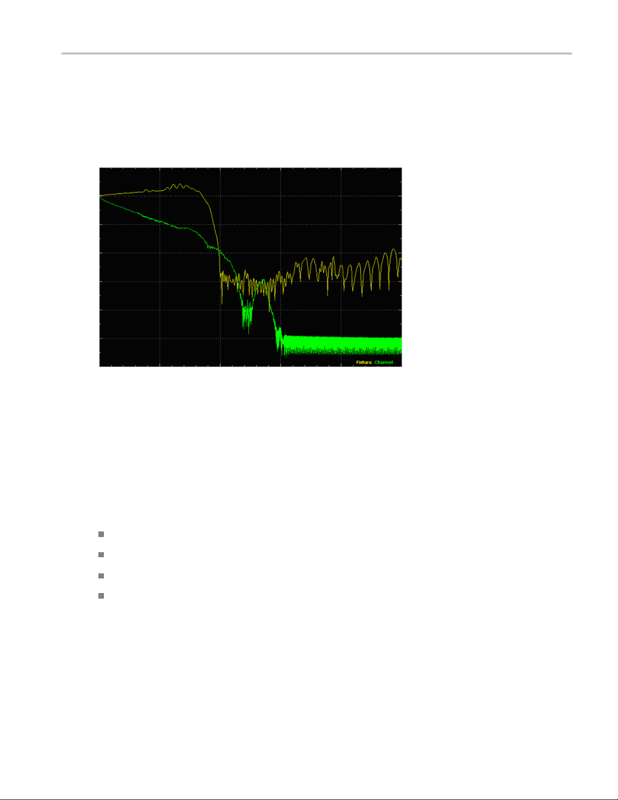
Reference Host Filter Information
The application uses the ‘Intel Host fixture.s4p’ S-parameter file to generate the filter response used
by USB-IF.
The filter response BW is 8 GHz and the stop band is 10 GHz at a -80 db roll off.
The following is a representative plot, generated using SDLA. You can use this plot as a reference plot, or
to view the response of the filter file.
Host fixture and channel response
nuous Time Linear Equalizer (CTLE) Filter
Conti
The USB3CTLE.flt filter is a Continuous Time Linear Equalizer (CTLE) filter. Due to the lossy nature of
hannel (the combination of the reference channel, cable, and test fixture from TX pins(TP1)), the
the c
eye diagram at the receiver may be closed. This filter applies receiver equalization to meet the system
timing and voltage margins.
The CTLE filter coefficients are generated by passing the following parameters to the SDLA:
ain (Adc) = 0.667
DC g
Zero frequency (fz) = 650 MHz
first pole frequency (fp1) = 1.95 Ghz
Second pole frequency (fp2) = 5 GHz
The following is a representative plot, using SDLA, of the combined response of the convolution of
Embed, De-embed and CTLE filters. You can use this plot as a reference plot, o r to view the response
of the filter file.
TekExpress USB Automated Solutions Help 89
Page 100

Reference Host Filter Information
CTLE response
The signal connection path for HOST is HOST <-> TF (B c onnector) <-> 3 meter reference cable <->
standar
d (1 meter) SMA cable <-> Oscilloscope channel.
NOTE. These filters are applicable for 12.5 GHz and above oscilloscopes. For 8 GHZ oscilloscopes,
only the embed filters BW (8 GHz) and stop band (10 GHz) are different; the de-embed parameters
remain the same.
See Also:
De-Embeding and Channel Embedding Overview (see page 87)
Device Filter Information (see page 91)
DUT/Filter Combinations (see page 93)
90 TekExpress USB Automated Solutions Help
 Loading...