

Page 1

xx
ZZZ
TekExpress
®
Thunderbolt Transmitter Automated Solution
Printable Online Help
*P077069200*
077-0692-00
Page 2

Page 3

TekExpress
®
Thunderbolt Transmitter Automated Solution
ZZZ
PrintableOnlineHelp
www.tektronix.com
077-0692-00
Page 4

Copyright © Tektronix. All rights reserved. Licensed software products are owned by Tektronix or its
subsidiaries or suppliers, and are protected by national copyright laws and international treaty provisions.
Tektronix products are covered by U.S. and foreign patents, issued and pending. Information in this
publication supersedes that in all previously published material. Specifications and price change privileges
reserved.
TEKTRONIX and TEK are registered trademarks of Tektronix, Inc.
TekExpress is a registered trademark of Tektronix, Inc.
TekExpress Thunderbolt Transmitter Automated Solution O nline Help, 076-0276-00.
Contacting Tektronix
Tektroni
14150 SW Karl Braun Drive
P.O. B o x 5 0 0
Beaverton, OR 97077
USA
x, Inc.
For pro
duct information, sales, service, and technical support:
In North America, call 1-800-833-9200.
Worldwide, visit www.tektronix.com to find contacts in your area.
Page 5

Table of Contents
Getting help and support
Related documentation............................................................................................. 1
Conventions used in help .......................................................................................... 1
Technical support ................................................................................................... 2
Getting started
Installing the Thunderbolt software
Install the Thunderbolt software ................ ................................ ............................. 3
Activate the license ............................................................................................ 3
View software version and license information ................. .................................. ......... 4
Installing the TenLira software
Install the TenLira software and test scripts ..... ................................ ........................... 5
Introduction to the application
Thunderbolt key features...................................................................................... 6
Supported oscilloscopes....................................................................................... 6
Minimum system requirements ........... ................................ .................................. . 7
Application directories and files ............................................................................. 8
File name extensions .......................................................................................... 9
Table of Contents
Operating basics
Run the application ................................................................................................ 11
Exit the application ................................................................................................ 11
Application controls and menus
Application controls .......................................................................................... 12
Options menu
Options menu overview ........... ................................ ................................ ...... 13
Instrument control settings .... .... .... . .... .... .... .... .... . .... .... .... .... .... . ... . .... .... .... .... . .. 14
Email settings
Email Settings dialog box overview .. .... . ... . ... . .... .... .... .... .... .... .... .... .... .... . ... . .. 14
Configure email settings... .... .... .... .... .... .... . ... . ... . .. . . .. . . .. . . .. . . .. . . .... .... .... .... .... 15
Deskew........ .................................. ................................ .......................... 16
Application panels
Application panel overview ................................................................................. 18
Setup panel
Setup panel overview.................................................................................... 18
Set DUT parameters ..................................................................................... 18
Select tests ................................................................................................ 21
Set acquisition parameters source .... .... .... .... .... .... .... .... .... .... .... . ... . ... . .. . . .. . . .. . . .. . . . 22
TekExpress Thunderbolt Transmitter Printable Online Help i
Page 6

Table of Contents
Settestnotification preferences ............ ................................ ............................ 23
Configure test parameters
About configuring test parameters .... ................................ ............................ 24
Configure test parameters .................... ................................ ...................... 24
Common test parameters ........................................................................... 24
Status panel overview ........................................................................................ 26
Results panel
Results panel overview.................................................................................. 27
View test results.................................. ................................ ........................ 28
View test-related fi les.................................................................................... 29
Reports panel
Reports panel overview ................................................................................. 29
Select report options ..................................................................................... 30
View a report ........... .................................. ................................ ................ 32
Report contents........................................................................................... 33
Setting up and configuring tests
About setting up tests ........... .................................. ................................ ................ 35
Equipment connection setup ..................................................................................... 36
View connected instruments.......................... .................................. .......................... 38
Test setup overview . .................................. ................................ ............................ 39
Running tests
About running tests................................................................................................ 41
Before you click Start ............................................................................................. 41
Pre-run checklist........................... ................................ ................................ ........ 43
Saving and recalling test setups
Test setups overview .................... .................................. ................................ ........ 45
Save a test setup ................................................................................................... 45
Recall a saved test setup .......................................................................................... 46
Create a new test setup based on an existing one .............................................................. 46
TekExpress programmatic interface
About the programmatic interface ............................................................................... 47
Requirements for developing TekExpress client ............................................................... 48
Remote proxy object .................... ................................ ................................ .......... 49
Client proxy object .......................... ................................ ................................ ...... 49
Client programmatic interface overview........................................................................ 51
Program remote access code example............... .................................. .......................... 54
Thunderbolt application commands
Thunderbolt application commands flow .......................... ................................ ........ 56
ii TekExpress Thunderbolt Transmitter Printable Online Help
Page 7

Table of Contents
Connect through an IP address.......... ................................ .................................. .. 61
Lock the server................................................................................................ 62
Disable the po
Set or get the DUT ID.... ................................ ................................ .................... 64
Set the configuration parameters for a suite or measurement ............................................ 65
Query the configuration parameters for a suite or measurement ...... ................................ .. 67
Select a test .......... ................................ ................................ .......................... 68
Select a suite................................................................................................... 69
Select a ch
Configure the selected measurement ... .................................. ................................ .. 71
Run with set configurations or stop the run operation .............................. ...................... 72
Handle error codes............................................................................................ 73
Get or set the timeout value.................................................................................. 74
Wait for the test to complete................................................................................. 75
he test is complete..................................................................................... 77
After t
Save, recall, or query a saved session .. .................................. ................................ .. 80
Unlock the server ... ................................ ................................ .......................... 81
Disconnect from the server ........ ................................ ................................ .......... 81
pups........................................ .................................. .................. 63
annel ................... ................................ ................................ ............ 70
Thunderbolt tests
PHY 1
PHY 1.2 Fall Time measurement .. .................................. ................................ ............ 83
PHY 1.3 Intra Pair Skew test........... .................................. ................................ ........ 83
PHY 1.4 AC common mode voltage Peak to Peak .......... ................................ .................. 83
PHY 1.5 Eye Height measurement ........................ ................................ ...................... 83
PHY 1.6 Eye Width measurement ............... .................................. .............................. 84
PH
PHY 1.8 Total Jitter measurement............................................................................... 84
PHY 1.9 Unit Interval (min) measurement ..... ................................ ................................ 84
PHY 1.10 SSC Modulation Frequency measurement ......................................................... 84
.1 Rise Time measurement . ................................ ................................ .............. 83
Y 1.7 Max Differential Voltage measurement.. ................................ ............................ 84
Reference
Map the My TekExpress folder .................... .................................. ............................ 86
Measurement parameter descriptions.......................................... .................................. 86
Index
TekExpress Thunderbolt Transmitter Printable Online Help iii
Page 8

Table of Contents
iv TekExpress Thunderbolt Transmitter Printable Online Help
Page 9

Getting help and support Related documentation
Related documentation
The following manuals are available as part of the TekExpress Thunderbolt Automated Solution
documentation set.
Table 1: Product documentation
Item Purpose Location
Online Help
PDF of the Online Help
xxx
See also
In-depth op
In-depth op
eration and UI help
eration and UI help
Applicatio
Applicatio
Downloadable file from w w w.tektronix.com
n Help menu
n Help menu
Technica
l Support
(see page 2)
Conventions used in help
Online Help uses the following conventions:
The term “DUT” is an abbreviation for Device Under Test.
The terms “click” and “select” are generic terms that mean to select an item in the application user
interface (UI). You can use a mouse or the touch screen to select UI items.
TekExpress Thunderbolt Transmitter Printable Online Help 1
Page 10

Getting help and support Technical support
Technical support
Tektronix values your feedback on our products. To help us serve you better, please send us your
suggestions, ideas, or comments on your application or oscilloscope. Contact Tektronix through mail,
telephone, o
When you contact Tektronix Technical Support, please include the following information (be as specificas
possible):
r the Web site. See Contacting Tektronix
General information
All instrument model numbers
for more information.
Hardware
Probes used
Yo ur name, company, mailing address, phone number, FAX number
Please indicate if you would like to be contacted by Tektronix about your suggestion or comments.
options, if any
Application specific information
Software version number
Description of the problem such that technical support can duplicate the problem
If possible, save the setup files for all the instruments used and the application.
If possible, save the TekExpress setup files, log.xml, *.TekX (session files and folders), and status
messages text file.
2 TekExpress Thunderbolt Transmitter Printable Online Help
Page 11

Getting started Install the Thunderbolt software
Install the Thunderbolt software
The TekExpress Thunderbolt web installer page provides a link to the software package Tbolt WebInstaller
1.0.0.0.exe used to install the application on a supported oscilloscope. For a list of compatible instruments,
see Supported oscilloscopes and probes
To download and install the files:
1. Close the TekScope application.
2. Go to the www.tek.com Web site and search for Thunderbolt to locate the installation file. Download
the file
3. If you downloaded the file to a PC, copy the file to the oscilloscope.
Tbolt WebInstaller 1.0.0.0.exe.
(see page 6).
4. Double-c
After extraction, the installer launches and the software automatically installs in the following location:
5. To run the application, open the TekScope application and select Analyze > TekExpress Thunderbolt.
lso
See a
Minimum system requirements (see page 7)
Supported oscilloscopes and probes (see page 6)
lick the executable file to extract the installation files.
Windows 7 location: C:\Program Files (x86)\Tektronix\TekExpress\TekExpress
Thunderbolt
Windows XP location: C:\Program Files\Tektronix\TekExpress\TekExpress
Thunderbolt
Activate the license
Activate the license using the Option Installation wizard on the oscilloscope. The oscilloscope Online Help
has instructions for using the Options Installation window to activate licenses for installed applications.
Follow these steps to activate the TekExpress Thunderbolt license:
1. From the oscilloscope menu, click Utilities > Option Installation. The TekScope Option Installation
wizard opens.
2. Press the F1 key on the oscilloscope keyboard to open the Option Installation help topic. Follow the
directions in the topic to activate the license.
TekExpress Thunderbolt Transmitter Printable Online Help 3
Page 12

Getting started View software version and license information
See also
View software version and license information (see page 4)
View software version and license information
The following instructions show how to view version and license information for the application and
associated modules such as the Programmatic Interface and the Programmatic Interface Client.
To view version information:
1. From the Options menu, select About TekExpress.
2. Click the
the dialog box when finished.
ew license information:
To vi
1. In the TekScope application, select Help > About TekScope.
View Version Details link to check the version numbers of the installed test suites. Close
The Options section in the dialog box displays a list of installed options, including Thunderbolt:
Transmitter solution.
2. Look in the Option Installation Key section for option key information.
ee also
S
Activate the license (see page 3)
Options menu (see page 13)
4 TekExpress Thunderbolt Transmitter Printable Online Help
Page 13

Getting started Install the TenLira software and test scripts
Install the TenLira software and test scripts
TenLira is a software utility (provided by the Intel corporation) used to control the DUT. The electrical
test scripts are used to control the Device DUT.
NOTE. Obtain
Business Link (IBL) portal to download the necessary files.
ing the TenLira software and compliance scripts requires that you have access to the Intel
TenLira software
1. Download the latest TenLira folder from the IBL library. Save the folder to your C: drive.
2. In the TenLira folder, open the SETUP_CTS_EDITION folder.
3. Double cl
4. Click NEXT and Close as needed.
5. When the window closes, go to the CMD window and follow the instructions until the installation is
complete.
6. Upon completion, the oscilloscope automatically restarts. (Restart manually if necessary.)
Thund
1. Download the latest Thunderbolt Electrical Compliance Scripts from the IBL library.
2. Navigate to the TenLira program folder.
erbolt electrical compliance scripts
ick TenLiraSetup_x86 bat file to start the installation.
Windows 7: C:\Program Files x86\Intel Corporation\TenLira
Windows XP: C:\Program Files\Intel Corporation\TenLira
3. Create a folder named “TBT Electrical”.
ace the T hunderbolt Electrical Compliance Scripts in the TBT Electrical folder.
4. Pl
TekExpress Thunderbolt Transmitter Printable Online Help 5
Page 14

Getting started Thunderbolt k ey features
The Thunderbolt application uses the following executables to control the Device DUT when using
the Custom mode.
CIO_Host_TX_PRBS9.exe
CIO_Host_TX_PRBS31.exe
CIO_Host_TX_SQ6.exe
Thunderbol
Welc ome to
ThunderboltTX provides an automated, simple, and efficient way to test Thunderbolt Transmitter interfaces
and devices consistent to the requirements of the Thunderbolt Base Specification v0.6.
Thunderbolt is based on TekExpress version 2, the Tektronix Test Automation Framework developed to
support your current and future test automation needs. TekExpress uses a highly modular architecture that
lets you quickly deploy automated test solutions for various standards.
Key Thunderbolt transmitter testing features include:
t key features
the TekExpress
Automated testing reduces the complexity of executing transmitter tests and enables you to test
devices faster
Seamless debug allows pause on each test in automation, and switch to DPOJET analysis tool for
detailed debug
®
Thunderbolt Transmitter Automated Solution application (Option TBT-TX).
Supported oscilloscopes
The TekExpress Thunderbolt application runs on the following Tektronix oscilloscopes:
O/DSA/MSO71604/B/C
DP
DPO/DSA/MSO72004/B/C
DPO/DSA72504D
DPO/DSA73304D
See also
Minimum system requirements (see page 7)
6 TekExpress Thunderbolt Transmitter Printable Online Help
Page 15

Getting started Minimum system requirements
Minimum system requirements
The following table shows the minimum system requirements for an oscilloscope to run TekExpress.
Table 2: System requirements
Oscilloscope Supported oscilloscopes (see page 6)
Processor
Operating System Same as the oscilloscope:
Memory
Hard Disk
Display
Firmware
Software
Same as the oscilloscope
Windows XP (32-bit) SP2 and higher
Windows 7 32-bit or 64-bit
Same as the oscilloscope
Same as the oscilloscope
Same as the oscilloscope
1
TekScope v5.3.4.25 (Windows XP),
TekScope v6.2.0.26 and above (Windows 7)
National Instruments LabVIEW Runtime 9.0.1 or later
National Instruments TestStand engine 4.2.1
Matlab Runtime engine v7.6 (Windows XP),
Matlab Runtime engine v7.14 (Windows 7)
Microsoft .NET 4.0 Framework
Microsoft Excel 2002 or above
Microsoft Internet Explorer 6.0 SP1 or later
Adobe Reader 7.0 or equivalent software for viewing portable document
format (PDF) files
DPOJET
v3.5.1.4 and above
Other Devices Matched pair of SMA cables, one-set minimum for single lane
Microsoft compatible mouse or compatible pointing device
xxx
1
If TekExpress is running on an instrument having a video resolution lower than 8 00x600 (for example, sampling oscilloscope), it is recommended
at you connect a secondary monitor. The secondary monitor must be configured and active before launching the application.
th
2
If TekExpress is installed on a Tektronix oscilloscope, TekExpress uses a virtual GPIB port to communicate with oscilloscope applications. If external
GPIB communication devices such as USB-GPIB-HS or equivalent are used for instrument connectivity, make sure that the Talker Listener utility is
enabled in the DPO/DSA/MSO oscilloscope GPIB menu. For ease of use, connect to an external (secondary) monitor.
See also
Supported oscilloscopes (see page 6)
Equipment connection setup (see page 36)
TekExpress Thunderbolt Transmitter Printable Online Help 7
Page 16
Getting started Application directories and files
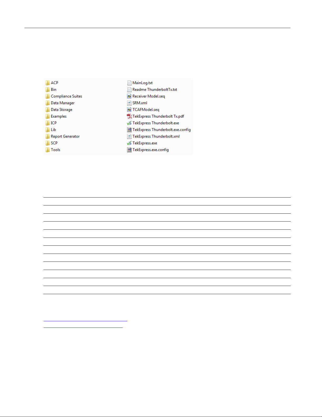
Application directories and files
The application directory and associated files are organized as follows:
The following table lists the default directory names and their usage:
Table 3: Application directories
Directory names Contains
InstallDir\TekExpress\TekExpress Thunderbolt Application and associated files
TekExpress Thunderbolt\ACP Instrument and Thunderbolt application-specific interface libraries
TekExpress Thunderbolt\B in
TekExpress Thunderbolt\Compliance Suites Compliance-specific files
TekExpress Thunderbolt\Data Manager Result management-specific libraries of the Thunderbolt application
TekExpress Thunderbolt\Data Storage Libraries needed for storing data
TekExpress Thunderbolt\Examples Various support files
TekExpress Thunderbolt\ICP Instrument and Thunderbolt application-specific interface libraries
TekExpress Thunderbolt\Lib Contains utility files specific to the Thunderbolt application
TekExpress Thunderbolt\Report Generator Excel Active X interface Library for Report Generation
TekExpress Thunderbolt\SCP Instrument and Thunderbolt application-specific interface libraries
TekExpress Thunderbolt\Tools Instrument and Thunderbolt application-specific files
xxx
Miscellaneous Thunderbolt application libraries
See also
View test-related files (see page 29)
File name extensions (see page 9)
8 TekExpress Thunderbolt Transmitter Printable Online Help
Page 17

Getting started File name extensions
File name extensions
The Thunderbolt application uses the following file name extensions:
File name extension Description
.TekX
.seq
.xml
.wfm Test waveform files
.mht
.xls
.csv
.html
xxx
See also
Saved session files. The extensions may not be displayed.
Test sequence files
Encrypted XML files that contain test-specificconfiguration information
Note that the log file extension is also xml
Test result reports (default format).
Select r
eport options
(see page 30)
View test-related files (see page 29)
Application directories and files (see page 8)
TekExpress Thunderbolt Transmitter Printable Online Help 9
Page 18

Getting started File name extensions
10 TekExpress Thunderbolt Transmitter Printable Online Help
Page 19

Operating basics Run the application
Run the application
To run the Thunderbolt application, do either of the following:
Select Analyze > TekExpress Thunderbolt from the TekScope menu.
Double-click any saved Thunderbolt session file.
When you open the application after installation, the application checks for a file called
located in the My TekExpress folder. If this file is not found, instrument discovery is performed before
launching Thunderbolt. The
available on your network.
If the application license was not installed using the TekScope menu Utilities > Option Installation
selection, you can open the application up to 10 times in evaluation mode. Each time you open the
application without supplying a valid license key, one of the free trials is used.
See also
Activa
te the license
(see page 3)
Exit the application
Use the following method to exit the application:
. Using other methods to exit the application results in abnormal termination of the application.
NOTE
Resources.xml
Resources.xml file contains information regarding instruments that are
1. Click on the application title bar.
2. Do one of the following:
you have an unsaved session or test setup open, you are asked to save it before exiting. To save
If
it, click Yes. Otherwise click No. The application closes.
message box appears asking if you really want to exit TekExpress. To exit, click Ye s .
A
TekExpress Thunderbolt Transmitter Printable Online Help 11
Page 20

Operating basics Application controls
Application controls
Table 4: Application control descriptions
Item Description
Options menu (see page 13) Opens the Options menu for access to global controls
Panels (see page 18) Visual frames with sets of related options
Command buttons Buttons that initiate an immediate action such as the Start, Stop, Pause,
Continue, and Clear command buttons
Start button
Starts continuous measurement acquisition and accumulation. If prior
acquired measurements have not been cleared, the new measurements
are added to the existing set.
Stop button
Stops (aborts) the current measurement acquisition.
Pause \ Continue button
Clear button
r Log
Clea
Save
lication window move icon
App
xxx
Use the
a test is paused, the button name changes to Continue.
Clears all existing measurement results. Adding or deleting a measurement,
or cha
clears measurements. This prevents t he accumulation of measurement
statistics or sets of statistics that are not coherent. This button is available
only o
This button is available only on the Status panel (see page 26).
This button is available only on the Status panel (see page 26).
Pl
application window. When the cursor changes to a hand, drag the window
to the desired location.
Pause button to temporarily interrupt the current acquisition. When
nging a configuration parameter of an existing measurement, also
ntheResults panel
ace the cursor over the three-dot pattern in the upper left corner of the
(see page 27).
12 TekExpress Thunderbolt Transmitter Printable Online Help
Page 21
Operating basics Options menu overview
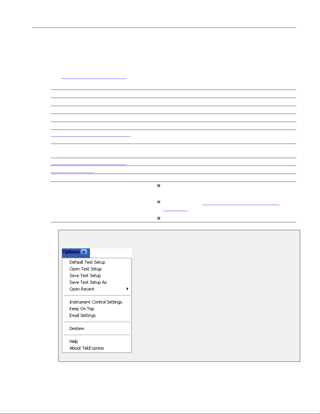
Options menu overview
The Options menu is located in the upper right corner of the application.
The Options menu
Menu Function
Default Test Setup Opens an untitle d test setup with defaults selected
Open Test Setup Opens a saved test setup
Save Test Setup Saves the current test setup selections
Save Test Setup As Creates a new test setup based on an existing one
Open Recent Displays a menu of recently opened test setups from which to select
Instrument Control Settings (see page 14) Shows the list of instruments connected to the test setup and allows
Keep On Top Keeps the TekExpress Thunderbolt utility on top of other open
Email settings dialog box (see page 14) Use to configure email options for test run and results notifications
Deskew (see page 16)
Help Displays TekExpress Help
About TekExpress
xxx
(see page 13) has the following selections:
you to locate and refresh connections to connected instruments
windows on the desktop
Loads oscilloscope channel deskew settings into the application.
Displays application details such as software name, version
number, and copyright
Provides access to software version and license information
(see page 4) for your Thunderbolt installation
Provides a link to the Tektronix Web site
Options menu
TekExpress Thunderbolt Transmitter Printable Online Help 13
Page 22
Operating basics Instrument control settings
See also
Application controls (see page 12)
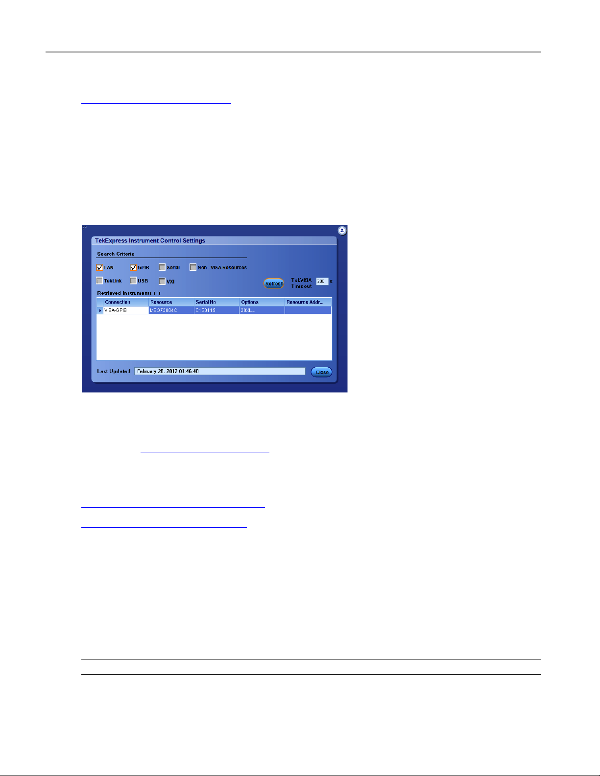
Instrument control settings
Use the TekExpress Instrument Control Settings dialog box to search for and list the connected resources
(instruments) found on specified connections (LAN, GPIB, USB, and so on) and each instruments
connection information. You access this dialog box from the Options menu.
Use the Instrument Control Settings feature to and view instrument connection details. Connected
instruments displayed here can be selected for use in the Global Settings tab in the configuration section.
See step 1 of Configure Tests
(see page 24) for details.
See also
View connected instruments (see page 38)
Options menu overview (see page 13)
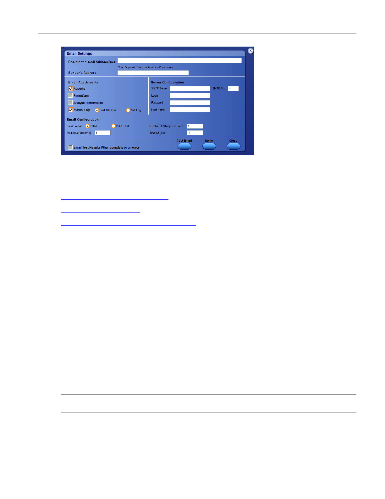
Email Settings dialog box overview
Use the Email Settings dialog box to enable Thunderbolt to send an email message when a test completes,
produces an error, or fails. Select the type of test run information to attach to the email (such as test reports
and test logs), t he email message format, and the email message size limit.
Open the Email Settings dialog box from the Options menu.
NOTE. Recipient email address, sender’s address, and SMTP Server are mandatory fields.
14 TekExpress Thunderbolt Transmitter Printable Online Help
Page 23
Operating basics Configure email settings
See also
Configure email settings (see page 15)
Options menu (see page 13)
Select t
est notification preferences
Configure email settings
To be notified by email when a test completes, fails, or produces an error, configure the email settings.
1. Select Options > Email Settings to open the Email settings dialog box.
2. (Required) For Recipient email Address(es), enter one or more email addresses to which to send the
test notification. To include multiple addresses, separate the addresses with commas.
3. (Required) For Sender ’s Address, enter the email address used by the instrument. This address consists
of the instrument name, followed by an underscore, followed by the instrument serial number, the @
symbol and then the email server used. For example: DPO72004C_B130099@yourcompany.com.
4. (Required) In the Server Configuration section, type the SMTP Server address of the Mail server
configured at the client location, and the SMTP Port number, in the corresponding fields.
If this server requires password authentication, enter a valid login name, password, and host name
in the corresponding fields.
NOTE. If any of the above required fields are left blank, the settings will not be saved and email
notifications will not be sent.
(see page 23)
TekExpress Thunderbolt Transmitter Printable Online Help 15
Page 24

Operating basics Deskew
5. In the Email Attachments section, select from the following options:
Reports: Attach the test report to the notification email.
Status Log: Attach the test status log to the notification email. If you select this option, then also
select whether you want to receive the full log or just the last 20 lines.
6. In the Email Configuration section:
Select the message file format to send: HTML (the default) or plain text.
7. Select th
8. To test y
9. To apply your settings, click Apply.
10. Click Close when finished.
Deskew
The Deskew utility reads the instrument configuration and channel deskew settings from the connected
oscilloscope and stores them in a file. When you run a test (click the Start button), Thunderbolt resets
the oscilloscope to the factory default settings, loads the instrument configuration and channel d eskew
set
instrument is set to a known state before each test run.
Enter a maxi
attachments larger than this limit will not be sent. The default is 5 MB.
Enter the n
system makes to send a notification. The default is 1. You can also specify a timeout period.
e Email Test Results When complete or on error check box. Use this check box to quickly
enable or disable email notifications.
our email settings, click Test E m ail.
tings with the saved values, and then starts running the test session. This is to make sure that the
mum file size for the email message (message plus attachment files). Messages with
umber in the Number of Attempts to Send field, to limit the number of attempts that the
NOTE. Make sure that you run the Thunderbolt Deskew utility after you have finalized the DUT setup,
oscilloscope settings, and channel deskew values, and before you run compliance tests with that test
configuration. See your oscilloscope user documentation or online help for information on channel
deskew procedures.
NOTE. You will need to run the Deskew utility whenever you change the oscilloscope settings or channel
deskew values for a test setup.
NOTE. Thunderbolt does not verify that the saved oscilloscope settings and d eskew values are applicable
to the current instrument attached to the application.
16 TekExpress Thunderbolt Transmitter Printable Online Help
Page 25
Operating basics Deskew
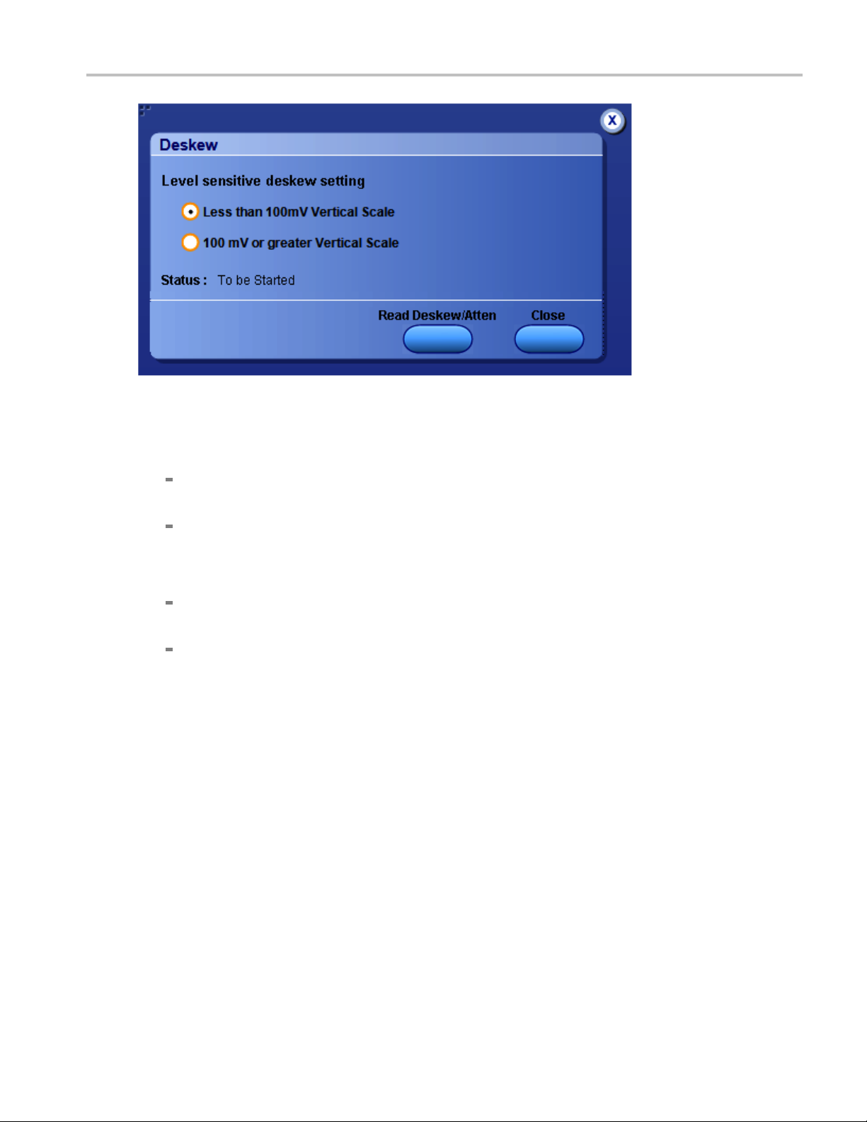
1. In the TekExpress Thunderbolt application, select Options > Deskew.
2. Select the level sensitive deskew setting:
Less than 100 mV Vertical Scale: Select this if the oscilloscope vertical setting is less than
100 mV/division for the signal you are measuring.
100 mV or greater Vertical Scale: Select this if the oscilloscope vertical setting is greater than
100 mV/division for the signal you are measuring.
3. Click Read Deskew/Attn. The utility stores the instrument settings and deskew settings as follows:
<100 mV: C:\Program Files\Tektronix\TekExpress \TekExpress Thunderbolt\ICP\Deskew-
Attenuation.txt
≥100 mV: C:\Program Files\Tektronix\TekExpress\TekExpress Thunderbolt\ICP\Deskew-
Attenuation-GE100mV.txt
4. When the status in the dialog box indicates the deskew is finished, click Close.
TekExpress Thunderbolt Transmitter Printable Online Help 17
Page 26

Operating basics Application panel overview
Application panel overview
Panels group related configuration, test and results settings.
The TekExpress Thunderbolt panels are:
Table 5: Application panels
Panel name Description
Setup
(see page 18)
Status
(see page 26)
Results
(see page 27)
Reports
(see page 29)
xxx
See also
Set the DUT, test, acquisition, and report parameters.
View the progress and analysis status of the selected tests, and view test logs.
View a summary of test results and select results viewing pref
Browse for reports, save reports as specific file types, specif
report content to include (such as summary information, detailed information, user comments,
setup configuration, application configuration), and select report viewing options.
erences.
y report naming conventions, select
Application controls (see page 12)
About setting up tests (see page 35).
Setup panel overview
The Setup panel contains sequentially ordered tabs that help guide you through a typical test setup process.
Set the DUT parameters
Select test(s)
(see page 21).
Set lane acquisition source
Configure the selected tests
Select test notification preferences
Items selected in a preceding Setup tab may change options available in the following tabs. You can switch
between the tabs in any order to modify your test parameters.
Set DUT parameters
(see page 18).
(see page 22).
(see page 24).
(see page 23).
Use the Setup panel DUT tab to select parameters for the device under test. The settings are global
and apply to all tests for the current session. DUT settings also affect the list of available tests in the
Test Selection tab.
18 TekExpress Thunderbolt Transmitter Printable Online Help
Page 27

Operating basics Set DUT parameters
1. Click Setup > DUT.
2. (Optional) Enter the ID for the device. The default value is DUT001. The DUT ID parameter is
addedtoreports.
3. (Optional) To
add comments to the test report, click the note pad icon (
)totherightoftheDUTID
field. Enter comment text up to 256 characters. To enable or disable displaying comments in the test
report, see Select report options
(see page 30).
4. Select from the following parameters. Settings that do not apply to compliance testing cannot be
changed and are grayed out.
Table 6: DUT tab settings
Setting Description
Acquire live waveforms Acquire active signals from the oscilloscope for testing.
Use pre-recorded
waveform files
View
Device Device
Version
Data Rates
Patterns
Number of Lanes to Test Select the desired number of test lanes to use for this test session. The lanes shown here
Run tests on a saved run session file. Select a run session file from the list.
Determines where to access the test configuration settings:
Compliance:Viewconfiguration settings by clicking Setup > Test Selection >
Configure
Advanced: Enables the Setup > Configuration tabinwhichtoviewconfiguration
settings.
Host
Select the Thunderbolt testing specification version to use for testing. The latest version
is the default.
Select the data rates to include in the tests.
10G is the only s election available at this time.
All patterns are selected by default. To exclude a pattern from a test, clear the check boxes.
determines the number of test lanes you can select.
TekExpress Thunderbolt Transmitter Printable Online Help 19
Page 28

Operating basics Set DUT parameters
Table 6: DUT tab settings (cont.)
Setting Description
Selected Test Lanes
SETUP
Displays the test lanes selected for the test session.
Click Setup to change lanes selected for testing.
a. In the Test Lane Setup dialog box, select the desired number of
lanes from the Link Width drop-down list.
b. To select the lanes to use, click the corresponding lane buttons:
To select both lanes at once, click Select All. If you select this,
select 2Lanesfrom the Number of Lanes to Test drop-down
list.
To deselect all selected lanes, click Deselect All.
If you select 1 Lane, select the Lane0 button.
If you select 2 Lanes, select Lane0 and Lane1.
c. Click OK.
Your selections display in the Link Width s ection of the DUT tab.
DUT Automation
The DUT Autom ation field displays the type of DUT control currently in use. DUT controls
are detected by through the Instrument Control Settings feature.
Manual: This option is displayed if your setup does not have the capability to control the
DUT automatically. You will be prompted to configure the DUT manually during the test.
You can change this to Custom if needed.
Custom: Select this option if you are using the TenLira custom utility to manage the D UT.
xxx
See also
About setting up tests (see page 35)
nLira software installation
Te
(see page 5)
20 TekExpress Thunderbolt Transmitter Printable Online Help
Page 29

Operating basics Select tests
Select tests
Use the Test Selection tab to select the tests to run on the connected DUT.
1. Click Setup > Test Selection.
2. Select the test(s) to run:
Click one or more check boxes adjacent to each test.
Click Desel
Click Select Required to select all tests that are required for compliance.
Click Select All to select all tests.
3. Configure the test(s):
Click Configure to open the configuration settings for a selected test.
NOTE. The Configure button is not displayed if the View in the DUT tab is set to Advanced.
Click Schematic to display a schematic diagram that shows the DUT test setup. Use the diagram
to verify the test setup before running the test.
ect All to deselect all tests. All tests are selected by default.
See also
About setting up tests (see page 35)
TekExpress Thunderbolt Transmitter Printable Online Help 21
Page 30

Operating basics Set acquisition parameters source
Set acquisition parameters source
Use the Acquisitions tab to set the signal source (channel) used to acquire data. Acquisition options are
available only when acquiring a live waveform.
1. Click Setup > Acquisitions.
2. Click the Lane 0 (+) and Lane 0 (-) fields to select the oscilloscope channels to use for those lanes.
3. ClickontheView Probes button to view the probe configuration of each oscilloscope channel.
4. Select an Acquisition and Save Options to determine the order in which waveforms are acquired and
analyzed.
Select Save All Waveforms Before Analysis to save all acquired waveforms before analysis
begins.
Select Analyze Immediately - No Waveform Saved to perform an analysis without saving
the waveform.
Select Save and Analyze Acquisition in Sequence to determine the order of acquisition and
analysis during the test execution.
5. Select Show Acquire Parameters to show the acquisition parameters in the test list.
6. Selec
7. Sele
t Acquire Step By Step to have the software prompt you to continue after each phase of the
test completes.
ct a Signal Validation parameter:
Select Prompt me if signal fails to open a dialog box when the application fails to acquire a valid
nal after a specified number of retries (as set in the Configuration tab or fields). Select one of
sig
the three options in the dialog box:
Acquire: The application attempts to re-acquire the signal.
Re-
Use Anyway: Use the acquired signal for all applicable tests.
Skip Test: Skip (ignore) any test(s) that depend on this acquisition. Skipped tests are listed in
the status panel and in the report.
Select Use signal as is - Don’t Check to skip signal validation and use the signal as-is for testing.
The test results may not be as expected.
22 TekExpress Thunderbolt Transmitter Printable Online Help
Page 31

Operating basics Set test notification preferences
Settestnotification preferences
Use the Preferences tab to set the application to send an email when a test measurement completes:
1. Click Setup > Preferences.
2. Select Highlight yellow warning if measured value is within [xx}% of limit check box to display a
yellow warning if the measured value is within the percent of limit value.
If you select this option, enter the margin limit value.
3. Select the On Test Failure, send me an email check box to receive an email when a test fails.
If you sele
Email Settings dialog box. Click Email Settings to configure the email settings
ct this option, select the EmailTestResultswhencompleteoronerrorcheck box in the
See also
About setting up tests (see page 35)
Select report options (see page 30)
(see page 15).
TekExpress Thunderbolt Transmitter Printable Online Help 23
Page 32

Operating basics About configuring test parameters
About configuring test parameters
Use the configuration settings to view the measurement parameters for selected tests. How the test
configurations are accessed depend on the View selected in the DUT tab.
If you selected Compliance View in the DUT tab, then in the Test Selection tab, select the desired test
in the list and then click the Configure button.
If you selected Advanced View in the DUT tab, click the Configuration tab in the Setup panel.
See also
Configure tests parameters
About running tests (see page 41)
Configure test parameters
The Configuration parameters let you set global and individual test parameters. To return to test selection
from the Configuration tab or panel, click the Test Selection button.
NOTE. You cannot change test parameters that are grayed out.
1. Modify Global settings (see page 24) as desired:
To select the instruments for testing, click Global Settings. In the Instruments Detected section,
click in the shaded areas to activate the drop-down lists and select an instrument. If you do not see
the desired instrument in the list, refresh the list
2. To modify any individual test measurement settings, click Measurements, select the test in the tree
view, and change the settings.
See also
About Setting Up Tests (see page 35)
(see page 38).
Common test parameters
The following table lists the setting
24 TekExpress Thunderbolt Transmitter Printable Online Help
s and parameters common to all tests.
Page 33

Operating basics Common test parameters
Table 7: Common parameters and values
Parameter type Parameter
Mode Determines whether test parameters are in compliance mode or can be edited
(User De fined Mode).
Compliance: Most test parameter values cannot be edited.
User Defined: Most test parameter values can be edited.
Global Settings These settings apply to all tests selected for the current session. You can
change only some of these settings.
Scope Settings: Specifies the instrument channel to use as the source for
the trigger
. This can be changed.
Measurements
Limits Editor
Channel Am
plitude: The value of the amplitude to be set for the selected
channel.
These sett
section. For details, see Measurement Parameter Descriptions
Shows the
ings apply to the test selected in the tree view of the configuration
(see page 86).
upper and lower limits for the applicable measurement using different
types of comparisons.
In Compliance Mode, you are able to view the measurement high and low limits
used for
When running tests in User Defined Mode, you can edit the limit settings
the test selected in the tree view of the Measurements tab.
(see
page 25) in the Limits Editor. When running tests in User Defined Mode, the cells
mits Editor table are active for editing so you can change parameters.
in the Li
When running tests in User Defined Mode, the cells in the Limits Editor
table are active for editing so you can change parameters.
xxx
ealso
Se
Configure tests (see page 24)
TekExpress Thunderbolt Transmitter Printable Online Help 25
Page 34

Operating basics Status panel overview
Status panel overview
The Status panel provides status on test acquisition and analysis (Test Status tab) and a listing of test tasks
performed (Log View tab). The application opens the Test Status tab when you start a test run. You can
select the Te
The Test Status tab lists a high level status for each test.
Table 8: Test Status tab
Column Description
Test Na me
Acquire Status,
Analysis
st Status or the Log View tab to view these items while tests are running.
Name of the test
Status of the signal acquisition or test analysis
Status
To be started
In progress
Test ing
Completed
Aborted
xxx
The Log View tab p rovides a list of the actions executed during the test. Use this information to review
or troubleshoot tests.
26 TekExpress Thunderbolt Transmitter Printable Online Help
Page 35

Operating basics Results panel overview
Table 9: Log View fields
Item Description
Message History
Show Detailed Log Records a detailed history of test execution.
Auto Scroll Sets the program to automatically scroll down the Message History window as information is added
Clear Log Clears all m
Save Saves the l
Displays all run messages with timestamp information.
to the log dur
the status messages in the file that you specify.
ing the test.
essages in the Message History window.
og file as a text file for examination. Displays a s tandard Save File window and saves
xxx
See also
View test results (see page 28)
Results panel overview
When a test finishes, the application switches to the Results panel to display a summary of test results.
Set viewing preferences for this panel from the Preferences menu in the upper right corner. Viewing
preferences include showing whether a test passed or failed, summary results or detailed results, and
enabling wordwrap. For information on using this panel, see View test results
(see page 28).
TekExpress Thunderbolt Transmitter Printable Online Help 27
Page 36

Operating basics View test results
View test results
When a test finishes, the application switches to the Results panel (see page 27), which displays a
summary of test results. The Overall Test Result is displayed at the top left of the Results table. If all of
the tests for the session pass, the overall test result will be Pass. If one or more tests fail, the overall test
result will show Fail.
Each test result occupies a row in the Results table. By default, results are displayed in summary format
with the measurement details collapsed and with the Pass/Fail column visible. Change the view in the
following ways:
To expand all tests listed, select View Results Details from the Preferences menu in the upper right
corner.
To expand and collapse tests, click the plus and minus buttons.
To collapse all expanded tests, select Preferences > View Results Summary.
To remove or restore the Pass/Fail column, select Preferences > Show Pass/Fail.
To enable or disable the wordwrap feature, select Preferences > Enable Wordwrap.
To expand the width of a column, place the cursor over the vertical line that se
from the column to the right. When the cursor changes to a double-ended arrow, hold down the mouse
button and drag the column to the desired width.
parates the column
To sort the test information by column, click the column head. When sorted in ascending order, a
small up arrow is displayed. When sorted in descending order, a small down arrow is displayed.
To clear all test results displayed, click Clear.
28 TekExpress Thunderbolt Transmitter Printable Online Help
Page 37

Operating basics View test-related files
See also
View a report (see page 32)
View test-related files
Files related to tests are stored in the My TekExpress\Thunderbolt folder. In the Thunderbolt
folder, each test setup has a test setup file and a test setup folder, both with the test setup name. The test
setup file is preceded by the Thunderbolt icon and usually has no visible file extension.
Inside the test setup folder is another folder named for the DUT ID used in the test sessions. The default
is DUT001.
Inside the DUT001 folder are the session folders and files. Each session has a folder and file pair, both
named for the test session using the naming convention (date)_(time). Each session file is stored outside
its matching session folder.
The first time you run a new, unsaved session, the session files are stored in the Untitled Session
folder located at ..\My TekExpress\Thunderbolt. When you name and save the session, the files are
placed in a folder with the name that you specify.
See also
File name extensions (see page 9)
Reports panel overview
Use the Reports panel to open reports, name and save reports, select report content to include, and select
report viewing options.
For information on setting up reports, see Select report options
reports, see View the report
(see page 30). For information on viewing
(see page 32).
TekExpress Thunderbolt Transmitter Printable Online Help 29
Page 38

Operating basics Select report options
Select r
Use the R
conventions to use for the report. For example, always give the report a unique name or select to have the
same name increment each time you run a particular test. Generally, you would select report options before
running a test or when creating and saving test setups. Report settings are included in saved test setups.
In the Reports panel, select from the following options:
eport options
eports panel
(see page 29) to select which test information to include in the report, and the naming
30 TekExpress Thunderbolt Transmitter Printable Online Help
Page 39

Operating basics Select report options
Table 10: Report options
Setting Description
Report Name
Displays the n
TekExpress\Thunderbolt\Untitled Session. The report file in this folder gets overwritten each time
you run a test unless you specify a unique name or select to auto increment the report name.
Change the re
ame and location from which to open a report. The default location is at \My
port name or location.
Do one of the f
ollowing:
In the Report Name field, type over the current folder path and name.
Double-click in the Report Name field. Make selections from the popup
keyboard and then click the Enter button.
Be sure to include the entire folder path, the file name, and the file type. For example:
C:\Documents and Settings\your user name\My Documents\My TekExpress\Thunderbolt
Tx\DUT001_Test_211.mht.
NOTE. You cannot change the file location using the Browse button.
Open an existing report.
Click Browse, locate and select the report file and then click View at the bottom of the panel.
Save As Type Saves a report in the specified file type. Lists supported file types to choose from.
NOTE. If you select a file type different from the default, be sure to change the report file name
extension in the Report Name field to match.
Auto increment report
name if duplicate
Include Pass/Fail
Results Summary
Include Detailed
Results
Include Setup
Configuration
Include Complete
Application
Configuration
Include User
Comments
View Report After
Generating
xxx
Sets the application to automatically increment the name of the report file if the application finds a
file with the same name as the one being generated. For example: DUT001, DUT002, DUT003.
This option is enabled by default.
Sets the application to include the color block labeled Test Result (indicating whether the test
passed or failed) in the report. For details, see Report Contents in View a Report
Sets the application to include parameter limits, execution time, and test-specific comments
generated during the test.
Sets the application to include information about hardware and software used i n the test in the
summary box at the top of the report. Information includes: the oscilloscope model and serial
number, probe model and serial number, the oscilloscope firmware version, SPC and factory
calibration status, and software versions for applications used in the m easurements.
Sets the application to include a table listing general, common, and acquired parameters used
in the test. This option is disabled by default.
Select to include any comments about the test that you or another user added in the DUT tab
of the Setup panel. Comments appear in the Comments section under the summary box at the
beginning of each report.
Automatically opens the report in your Web browser when the test completes. This option is
selected by default.
See also
(see page 32).
View a report (see page 32)
TekExpress Thunderbolt Transmitter Printable Online Help 31
Page 40

Operating basics View a report
About setting up tests (see page 35)
View a report
The application automatically generates a report when test analysis is completed and displays the report
in your default Web browser (unless you cleared the View Report After Generating checkboxinthe
Reports panel before running the test). If you cleared this check box, or if you want to view a different
test report
1. Click the Reports > Browse button and locate and select the report file to view.
, do the following:
NOTE. If y
you ran another test, the report file was not saved.
2. At the bo
For information on changing the file type, file name, and other report options, see Select Report Options
(see pa
ou did not save the test setup after running the test and you either closed the application or
ttom of the Reports panel, click View.
ge
30).
32 TekExpress Thunderbolt Transmitter Printable Online Help
Page 41

Operating basics Report contents
Report contents
A report shows specified test details, as d efined in the Reports panel.
Setup Configuration Information
Setup configuration information is listed in the summary box at the top of the report. This information
includes the oscilloscope model and serial number, probe model and serial number, and software versions.
To exclude this information from the report, clear the Include Setup Configuration check box in the
Reports panel before running the test.
User Comments
If you se
Setup panel appear in the Comments section directly below the summary box.
Test results
This
panel before running the test (Include Pass/Fail Results Summary, Include User Comments, Include
Detailed Results, Include Complete Application Configuration, and so on).
If Include Plots Images is selected, then measurement waveform plots are shown below the test results
table.
lected to include comments in the test report, any comments you added in the DUT tab of the
table lists the tests results. The contents of this table depend on the selections made in the Reports
TekExpress Thunderbolt Transmitter Printable Online Help 33
Page 42

Operating basics Report contents
See also
View test results (see page 28)
View test-related files (see page 29)
34 TekExpress Thunderbolt Transmitter Printable Online Help
Page 43

Setting up and configuring tests About setting up tests
About setting up tests
Set up tests using the tabs in the Setup panel. Settings in the DUT tab use a top-down, left-to-right logic
flow, so that any parameter that affects or acts as a filter for other parameters appears either to the top of or
to the left of
Tests are saved when you save a test setup. To avoid overwriting test results, remember to assign a unique
name to the t
See also
About test setups (see page 45)
the affected parameters.
est either before running it or immediately after.
Before yo
About running tests (see page 41)
u click Start
(see page 41)
TekExpress Thunderbolt Transmitter Printable Online Help 35
Page 44

Setting up and configuring tests Equipment connection setup
Equipment connection setup
The following diagrams shows how to connect the DUT to the oscilloscope for all the Thunderbolt
measurements.
Device connection diagram
36 TekExpress Thunderbolt Transmitter Printable Online Help
Page 45

Setting up and configuring tests Equipment connection setup
Host connection diagram
See also
Minimum system requirements (see page 7)
View connected instruments (see page 38)
About setting up tests (see page 35)
TekExpress Thunderbolt Transmitter Printable Online Help 37
Page 46

Setting up and configuring tests View connected instruments
View connected instruments
Use the Instrument Control Settings dialog box to view or search for connected instruments required for
the tests. The application uses TekVISA to discover the connected instruments.
To refresh the list of connected instruments:
1. From the Options menu, select Instrument Control Settings.
2. In the Search Criteria section of the Instrument Control Settings dialog box, select the connection
types of the instruments to search for.
Instrument search is based on the VISA layer but different connected cables determine the resource
type,suchasLAN,GPIB,andUSB.Forexample,if you choose LAN, the search will include all
the instruments supported by TekExpress that are communicating over the LAN. If the search does
not find any instruments that match a selected resource type, a message appears telling you that no
such ins
3. Click Refresh. TekExpress searches for connected instruments.
truments were found.
4. Afte
r discovery, the dialog box lists the i nstrument-related details based on the search criteria you
selected. For example, if you selected LAN and GPIB as the search criteria, the application checks for
the availability of instruments over LAN, then GPIB.
38 TekExpress Thunderbolt Transmitter Printable Online Help
Page 47

Setting up and configuring tests Test setup overview
The details of the instruments are displayed in the Retrieved Instruments table. The time and date of
instrument refresh is displayed in the Last Updated field.
See also
ts
Configure Tes
Equipment Setup (see page 36)
(see page 24)
Test setup overview
A test setup includes configuration parameters and report options. Use the options in the Setup panel and
Reports panel
(see page 29) to select and configure tests.
1. Select the DUT parameters
2. Select one or more tests
3. Configure tests
4. Select test notification preferences
5. Select
report options
(see page 24).
(see page 18).
(see page 21).
(see page 30).
See also
About test Setups (see page 45)
run checklist
Pre-
Before you click Start (see page 41)
About running tests (see page 41)
(see page 43)
(see page 23).
TekExpress Thunderbolt Transmitter Printable Online Help 39
Page 48

Setting up and configuring tests Test setup overview
40 TekExpress Thunderbolt Transmitter Printable Online Help
Page 49

Running tests About running tests
About running tests
After selecting and configuring the test, review the pre-run checklist (see page 43) and then click Start to
run the tests. While tests are running, you cannot access the Setup or Reports panels. To monitor the test
progress, sw
The application displays a report when the tests are complete. While the tests are running, other
applicatio
other applications, but you can switch to other applications by using the Alt + Ta b key combination. To
keep the TekExpress Thunderbolt application on top, select Keep On Top from the Thunderbolt Options
menu.
See also
About Configuring Tests (see page 24)
About Setting Up Tests (see page 35)
Before You Click Start (see page 41)
itch back and forth between the Status panel and the Results panel.
ns may display windows in the background. The TekScope application takes precedence over
Before you click Start
Before you run tests for the first time, do the following:
1. Unde
rstand where your test files are stored on the instrument.
After you install and launch TekExpress Thunderbolt, it creates the f ollowing folders on the
illoscope:
osc
\Program Files (x86)\Tektronix\TekExpress\TekExpress Thunderbolt
TE. The Program Files folder for Windows 7 is
NO
Windows XP uses
\My Documents\My TekExpress\Thunderbolt
\My Documents\My TekExpress\Thunderbolt\Untitled Session
Every time you launch TekExpress Thunderbolt, an Untitled Session folder is created in
the
Thunderbolt folder. The Untitled Session folder is automatically deleted when you
exit the Thunderbolt application.
Program Files
Program Files (x86)
.
for 64-bit.
TekExpress Thunderbolt Transmitter Printable Online Help 41
Page 50

Running tests Before you click Start
CAUTION. Do not directly edit or modify any of the session files or folders because this may result in
loss of data or corrupted session files. Each session has multiple files associated with it. When you
save a session, the application creates a .TekX file, and a folder named for the session that contains
associated fi
les, on the oscilloscope X: drive.
2. Map the shared My TekExpress folder (see page 86) as X: (X drive) on all instruments used in test
setup runni
The
Or, if the i
name><user ID>My TekExpress
ng Microsoft Windows Operating System.
My TekExpress folder has the shared name format <domain><user ID>My TekExpress.
nstrument is not connected to a domain, then the shared name format is
<instrument
. This shared folder is used to save the test session files and is
used during any other file transfer operations.
NOTE. If the X: drive is mapped to any other shared folder, the application will display a warning message
asking you to disconnect the X: drive manually.
3. Make sure that the My TekExpress folder has read and write access and that the contents are not set
to be encrypted:
a. Right-click the folder and select Properties.
b. Select the General tab and then click Advanced.
c. In the Advanced Attributes dialog box, make sure that the option Encrypt contents to secure
data is NOT selected. Example
42 TekExpress Thunderbolt Transmitter Printable Online Help
Page 51

Running tests Pre-run checklist
4. Review the pre-run checklist (see page 43) before you run a test.
See also
View Test-Related Files (see page 29)
Application Directories and Usage (see page 8)
File Name Extensions (see page 9)
Pre-run checklist
Do the following before you click Start to run a test. If this is the first time you are running a test for a
setup, refer to the information in Before You Click Start
On the oscilloscope:
(see page 41).
Make su
Perform Signal Path Compensation (SPC).
Perform deskew on any cables.
In the Thunderbolt application:
1. Ver
instruments (see page 38).
2. Run the Deskew utility (Options > Deskew).
re that all the required instruments are properly warmed up.
a. On the oscilloscope main menu, select the Utilities menu.
b. Select Instrument Calibration and run the SPC utility..
ify that the application is able to find the DUT. If it cannot, perform a search for connected
a. Sel
b. In the Configuration section, click Global Settings.
c. In the Instruments Detected section, click the drop-down arrow to the right of the listed
ect Setup > Test Selection. Select any test and then click Configure.
instruments and make sure that the instrument is listed.
See also
Equipment Connection Setup (see page 36)
TekExpress Thunderbolt Transmitter Printable Online Help 43
Page 52

Running tests Pre-run checklist
44 TekExpress Thunderbolt Transmitter Printable Online Help
Page 53

Saving and recalling test setups Test setups overview
Test setups overview
A test setup file contains the oscilloscope connection and setting information, general parameters,
measurement limits, test selections, and other settings for the current application configuration. This
information
test without having to do any other setup except ensuring that the correct oscilloscope is connected and
accessible by Thunderbolt.
See also
About setting up tests (see page 35)
Save a test setup (see page 45)
Recall a saved test setup (see page 46)
is saved to a file under the setup name. Use a saved test setup to quickly load and run a
Create a
new test setup based on an existing one
Save a test setup
Save a test setup before or after running a test using the parameters you want saved. Create a new test
from any open setup or from the default setup. When you select the default test setup, all application
setup
settings are returned to their defaults.
ollowing instructions start from the default test setup:
The f
1. Select Options > Default Test Setup.
2. Select Setup and set required options and parameters in the tabs (DUT, Test Selection, and so on).
3. Select Reports and set your report options
4. Click Start to run the test and verify that it runs correctly and captures the information y ou want. If it
does not, edit the parameters and repeat this step until the test runs to your satisfaction.
5. Select Options > Save Test Setup.Enterthefile name for the setup file. The application saves the file
to X:\Thunderbolt\<session_name>.
(see page 46)
(see page 30).
See also
About setting up tests (see page 35)
About configuring tests (see page 24)
Test setup overview (see page 39)
TekExpress Thunderbolt Transmitter Printable Online Help 45
Page 54

Saving and recalling test setups Recall a saved test setup
Recall a saved test setup
To recall a saved test setup:
1. Select Options > Open Test Setup.
2. Select the setup from the list and click Open.
See also
Test setups overview (see page 45)
Create a new test setup based on an existing one (see page 46)
Create a new test setup based on an existing one
Usethisproceduretocreateavariationonatestsetupwithout having to create the entire setup from the
beginning.
1. Select Options > Open Test Setup.
2. Select
3. Use the Setup and Reports panels to modify the parameters to meet your testing requirements.
4. Select Options > Save Test Setup As.
5. Enter a test setup name and click Save.
a setup from the list and then click Open.
See also
Test setups overview (see page 45)
46 TekExpress Thunderbolt Transmitter Printable Online Help
Page 55

TekExpress programmatic interface About the programmatic interface
About the programmatic interface
The Programmatic interface allows you to seamlessly integrate the TekExpress test automation application
with the high-level automation layer. This also allows you to control the state of the TekExpress
application
For simplifying the descriptions, the following terminologies are used in this section:
TekExpress Client: A high-level automation application that communicates with TekExpress using
TekExpress Programmatic Interface.
TekExpress Server: The TekExpress application when being controlled by TekExpress Client.
TekExpress leverages .Net Marshalling to enable the Programmatic Interface for TekExpress Client.
TekExpre
TekExpress client library is inherited from .Net MarshalByRef class to provide the proxy object for the
clients. The TekExpress client library maintains a reference to the TekExpress Server and this reference
allows the client to control the server state.
running on a local or a remote computer.
ss provides a client library for TekExpress clients to use the programmatic interface. The
also
See
Requirements for Developing TekExpress Client (see page 48)
Remote Proxy Object (see page 49)
Client Proxy Object (see page 49)
TekExpress Thunderbolt Transmitter Printable Online Help 47
Page 56

TekExpress programmatic interface Requirements for developing TekExpress client
Requirements for developing TekExpress client
While developing the TekExpress Client, use the TekExpressClient.dll. The client can be a VB .Net, C#
.Net, TestStand or Web application. The examples for interfaces in each of these applications are in the
Samples fold
References required
TekExpressClient.dll has an internal reference to IIdlglib.dll and IRemoteInterface.dll.
IIdlglib.dll has a reference to TekDotNetLib.dll.
IRemoteInterface.dll provides the interfaces required to perform the remote automations. It is an
interface that forms the communication line between the server and the client.
IIdlglib.dll provides the methods to generate and direct the secondary dialog messages at the client-end.
NOTE. The end-user client application does not need any reference to the above mentioned DLL files.
It is essential to have these DLLs (IRemoteInterface.dll, IIdlglib.dll and TekDotNetLib.dll) in the same
folder as that of TekExpressClient.dll.
er.
Required steps for a client
The following steps are used by the client to programmatically control the server using
TekExpressClient.dll:
Develop a client UI to access the interfaces exposed through the server. This client loads
TekExpressClient.dll to access the interfaces. After TekExpressClient.dll is loaded, the client
UI can call the specific functions to run the operations requested by the client. When the client is up and
running, it does the following to run a remote operation:
1. To connect to the server, the client provides the IP address of the PC where the server is running.
2. The client locks the server application to avoid conflict with any other Client that may try to control
the server simultaneously. “Lock” would also disable all user controls on the server so that server
state cannot be changed by manual operation.
If any other client tries to access a server that is locked, it will receive a notification that the server
is locked by another client.
3. When the client has connected to and locked the server, the client can access any of the programmatic
controls needed to run the remote automations.
4. After the client operations finish, the client unlocks the server.
See also
Thunderbolt application commands flow (see page 56)
48 TekExpress Thunderbolt Transmitter Printable Online Help
Page 57

TekExpress programmatic interface Remote proxy object
Remote proxy object
The server exposes a remote object to let the remote client access and perform the server-side operations
remotely. The proxy object is instantiated and exposed at the server-end through marshalling.
The following is an example:
RemotingConfiguration.RegisterWellKnownServiceType (typeof (TekExpressRemoteInterface), “TekExpress Remote interface”, WellKnownObjectMode.Singleton);
This object lets the remote client access the interfaces exposed at the server side. The client gets the
reference to this object when the client gets connected to the server.
For example,
//Get a reference to the remote object
remoteObject = (IRemoteInterface)Activator.GetObject(typeof(IRemoteInter face),
URL.ToString());
Client proxy object
Client exposes a proxy object to receive certain information.
TekExpress Thunderbolt Transmitter Printable Online Help 49
Page 58

TekExpress programmatic interface Client proxy object
For example,
//Register the client proxy object
WellKnownServiceTypeEntry[] e = RemotingConfiguration.GetRegisteredWellKnownServiceTypes();
clientInterface = new ClientInterface();
RemotingConfiguration.RegisterWellKnownServiceType(typeof(ClientInterface),
“Remote Client Interface”, WellKnownObjectMode.Singleton);
//Expose the client proxy object through marshalling
RemotingS
ervices.Marshal(clientInterface, "Remote Client Inteface");
The client proxy object is used for the following:
To get the secondary dialog messages from the server.
To get the file transfer commands from the server while transferring the report.
Examples
clientObject.clientIntf.DisplayDialog(caption, msg,iconType, btnType);
tObject.clientIntf.TransferBytes(buffer, read, fileLength);
clien
For more information, click the following links:
Secondary Dialog Message Handling
The s econdary dialog messages from the Secondary Dialog library are redirected to the client-end when a
client is performing the automations at the remote end.
In the secondary dialog library, the assembly that is calling for the dialog box to be displayed is checked
and if a remote connection is detected, the messages are directed to the remote end.
File Transfer Events
50 TekExpress Thunderbolt Transmitter Printable Online Help
Page 59

TekExpress programmatic interface Client programmatic interface overview
When the client requests the transfer of the report, the server reads the report and transfers the file by
calling the file transfer methods at the client-end.
Client programmatic interface overview
The following is an overview of the client programmatic interface:
Process flowchart
TekExpress Thunderbolt Transmitter Printable Online Help 51
Page 60

TekExpress programmatic interface Client programmatic interface overview
52 TekExpress Thunderbolt Transmitter Printable Online Help
Page 61

TekExpress programmatic interface Client programmatic interface overview
1. Connect to a server or remote object using a programmatic interface.
2. Get the client ID that is created when connecting to the remote object. This client ID is one of the
required parameters to communicate with the server.
NOTE. The server identifies the client with this ID only and rejects any request if the ID is invalid.
3. Lock the server for further operations. This disables the application interface.
NOTE. You can get values from the server or set values from the server to the client only if the application
is locked.
4. Register for receiving notifications on status change events on the server. To register you need to give
a handler as a parameter. For details, see Handler of Status Change Notification
NOTE. Whenever there is a change in the status of the server, all the clients registered with the server
receive a notification from the server.
(see page 53).
5. Select the tests to run through the programmatic interface.
6. Set the necessary parameters for each test.
7. Run the tests.
8. Poll for the status of the application.
NOTE. Skip this step if you are registered for the status change notification and the status is Ready.
9. After completing the tests, get the results.
eate a report or display the results and verify or process the results.
10.Cr
11. Unlock the server after completing all the tasks.
12. Disconnect from the remote object.
andler of Status Change Notification
H
1. Get the status. If the status is Wait or Error, get the information that contains the title, message
description, and the expected responses for the status.
2. Perform the actions based on the status information.
3. Set the response as expected.
TekExpress Thunderbolt Transmitter Printable Online Help 53
Page 62

TekExpress programmatic interface Program remote access code example
See also
Thunderbolt application commands flow (see page 56)
Program remote access code example (see page 54)
Program remote access code example
This code example shows how to communicate between a remote PC and TekExpress Thunderbolt.
Table 11: Remote access code example
Task Code
Start the
application
Connect through
an IP address.
Lock the server
Disable the
Popups
Set the DUT ID
Select a test
Runwithset
configurations
Wait for the test to
complete.
Get the current
state information
Send the
response
Save results 'Save all results values from folder for current run
Unlock the server
m_Client.Connect("localhost") 'True or False
clientID = m_Client.getClientID
m_Client.LockServer(clientID)
m_Client.SetVerboseMode(clientID, false)
m_Client.SetDutId(clientID, "DUT_Name")
For Device:
mClient.SelectsingleTest(clientID, "Device", "Source", "SPEC 0.6","
PHY 1.1_Rise Time measurement", true)
For Host:
mClient.SelectsingleTest(clientID, "Host", "Source", “SPEC 0.6”,"
PHY 1.1_Rise Time measurement", true)
m_Client.Run(clientID)
Do
Thread.Sleep(500)
m_Client.Application_Status(clientID)
Select Case status
Case "Wait"
mClient.GetCurrentStateInfo(clientID, WaitingMsbBxCaption,
WaitingMsbBxMessage, WaitingMsbBxButtontexts)
mClient.SendResponse(clientID, WaitingMsbBxCaption, WaitingMsbBxMessage, WaitingMsbBxResponse)
End Select
Loop Until status = "Ready"
m_Client.TransferResult(clientID, logDirname)
m_Client.UnlockServer(clientID)
54 TekExpress Thunderbolt Transmitter Printable Online Help
Page 63

TekExpress programmatic interface Program remote access code example
Table 11: Remote access c ode example (cont.)
Task Code
Disconnect from
m_Client.Disconnect()
server
Exit the
application
xxx
NI TestStand client example
The following is an example for NI TestStand Client available in the path: C:\Program
Files\Te
Interface\TestStand
ktronix\TekExpress\TekExpress Thunderbolt\Examples\Programmatic
TekExpress Thunderbolt Transmitter Printable Online Help 55
Page 64

TekExpress programmatic interface Thunderbolt application commands flow
Thunderbolt application commands flow
Click a client action link to see the associated command name, description, parameters, return value,
andanexample.
Connect through an IP address
(see page 61)
Lock the server (see page 62)
Disable the popups (see page 63)
Set or get the DUT ID (see page 64)
Set the configuration parameters for a suite or measurement (see page 65)
Query the configura tion parameters for a suite or measurement (see page 67)
Select a test (see page 68)
Select a suite (see page 69)
Select a channel (see page 70)
Configure the selected measurement (see page 71)
Run with set configurations or stop the run operation (see page 72)
Handle error codes (see page 73)
Get or set the timeout value (see page 74)
Wait for the test to complete (see page 75)
After the test is complete (see page 77)
Save, recall, or query a saved session (see page 80)
Unlock the server (see page 81)
Disconnect from the server (see page 81)
string id
Name Type Direction Description
id string IN
xxx
Ready: Test configured and ready to start
Running: Test running
Paused: Test paused
Wait: A popup that needs your inputs
Error: An error is occurred
Identifier of the client performing the
remote function
56 TekExpress Thunderbolt Transmitter Printable Online Help
Page 65

TekExpress programmatic interface Thunderbolt application commands flow
string dutName
Name Type Direction Description
dutName string IN
xxx
The new DUT ID of the setup
out bool saved
Name Type Direction Description
saved bool
xxx
OUT
This parameter is used as a check in SaveSession() and SaveSessionAs() functions.
Boolean representing whether the
current session is saved
string ip
Address
Name Type Direction Description
ipAddress string IN
The ip address of the server to which the
s trying to connect. This is required to
client i
establish the connection between the server
and the client.
xxx
out string clientID
Name Type Direction Description
clientid string
xxx
NOTE. If the dutName parameter is null, the client is prompted to provide a valid DUT ID.
NOTE. The server must be active and running for the client to connect to the server. Any number of
clients can be connected to the server at a time.
OUT Identifier of the client that is connected to the
server
clientId = unique number + ipaddress of the
client. For example, 1065–192.157.98.70
NOTE. When the client is disconnected, it is unlocked from the server and then disconnected. The id
is reused.
TekExpress Thunderbolt Transmitter Printable Online Help 57
Page 66

TekExpress programmatic interface Thunderbolt application commands flow
string dutId
Name Type Direction Description
dutId string
xxx
OUT The DUT ID of the setup
The dutId parameter is set after the server processes the request.
string device
Name Type Direction Description
device string IN
xxx
Specifies the name of the device
string suite
Name Type Direction Description
suite string IN
xxx
Specifies the name of the suite
string test
Name Type Direction Description
test
string IN
Specifies the name of the test to
obtain the pass or fail status
xxx
string parameterString
Name Type Direction Description
parameterString
xxx
string IN
Selects or deselects a test
int rowNr
Name Type Direction Description
rowNr int IN
xxx
NOTE. When the client tries to lock a server that is locked by another client, the client gets a
notification that the server is already locked and it must wait until the server is unlocked. If the client
locks the server and is idle for a certain amount of time then the server is unlocked automatically
from that client.
Specifies the zero based row index of
the sub-measurement for obtaining
the result value
58 TekExpress Thunderbolt Transmitter Printable Online Help
Page 67

TekExpress programmatic interface Thunderbolt application commands flow
out string[] status
Name Type Direction Description
status
string array
OUT The list of status messages generated
during the run
xxx
string name
Name Type Direction Description
name
string IN
The name of the session being
recalled
xxx
The name parameter cannot be empty. If it is empty, the client is prompted to provide a v alid name.
NOTE. When the run is performed, the status of the run is updated periodically using a timer.
string name
Name Type Direction Description
name
xxx
string IN
The name of the session being saved
The name parameter cannot be empty. If it is empty, the client is prompted to provide a v alid name.
Once the session is saved under ‘name’ you cannot use this method to save the session in a different
name. Use SaveSessionAs instead.
string name
Name Type Direction Description
name
string IN
The name of the session being
recalled
xxx
The same session is saved under different names using this method. The name parameter cannot be
empty. If it is empty, the client is prompted to provide a valid name.
bool isSelected
Name Type Direction Description
isSelected
xxx
bool IN
Selects or deselects a test
TekExpress Thunderbolt Transmitter Printable Online Help 59
Page 68

TekExpress programmatic interface Thunderbolt application commands flow
string time
Name Type Direction Description
time string IN The time in seconds
that refers to the timeout
period
xxx
The time parameter gives the timeout period, which is the time the client is allowed to be locked and
idle. After the timeout period if the client is still idle, it gets unlocked.
The time parameter should be a positive integer; otherwise, the client is prompted to provide a
valid timeout period.
bool_verbose
Name Type Direction Description
_verbose bool IN
xxx
Specifies whether the verbose mode
should be turned ON or OFF
NOTE. When the session is stopped, the client is prompted to stop the session and is stopped at
the consent.
string filePath
Name Type Direction Description
filePath
string IN The location where the report must
be saved in the client
xxx
NOTE. If the client does not provide the location to save the report, the report is saved at
C:\ProgramFiles.
NOTE. When the client is disconnected, the client is unlocked automatically.
out string WaitingMsbBxCaption
Name Type Direction Description
caption string
xxx
OUT
The wait state or error state message sent to
you
60 TekExpress Thunderbolt Transmitter Printable Online Help
Page 69

TekExpress programmatic interface Connect through an IP address
out string WaitingMsbBxMessage
Name Type Direction Description
message
xxx
string
OUT The wait state/error state message sent to you
out string[] WaitingMsbBxButtontexts
Name Type Direction Description
buttonTexts string array
OUT An array of strings containing the
possible response types that you can
send
xxx
string WaitingMsbBxResponse
Name Type Direction Description
response
string IN A string containing the response
type that you can select (it must be
one of the strings in the string array
buttonTexts)
xxx
out string clientID
Name Type Direction Description
clientID string
xxx
Connect through an IP address
Command name Parameters Description Return value Example
Connect()
xxx
string
ipAddress (see
page 57)
out string
clientID (see
page 57)
This method
connects the client
to the server.
Note
The client provides
the IP address
to connect to the
server.
The server
provides a unique
client identification
number when
connected to it.
OUT Identifier of the client that is connected to the
server
clientID = unique number + ipaddress of the
client. For example, 1065–192.157.98.70
Return value is
either True or
False
(see page 57)
m_Client = new Client()
//m_Client is a reference to the
Client class in the Client DLL.
returnval as boolean
returnval = m_Client.Connect(ipaddress,m_clientID)
TekExpress Thunderbolt Transmitter Printable Online Help 61
Page 70

TekExpress programmatic interface Lock the server
NOTE. The Fail condition for PI commands occurs in any of the following cases:
TheserverisLOCKEDandthemessagedisplayed is "Server is locked by another client".
ThesessionisUNLOCKEDandthemessagedisplayed is "Lock Session to execute the command".
The server is NOTFOUND and the message displayed is "Server not found...Disconnect!".
When none of
these fail conditions occur, then the m essage displayed is "Failed...".
Lock the server
Command name Parameters Description Return value Example
LockSession()
xxx
NOTE. The Fail condition for PI commands occurs in any of the following cases:
TheserverisLOCKEDandthemessagedisplayed is "Server is locked by another client".
string clientID
(see page 61)
This method locks
the server.
Note
(see page 58)
The client must
call this method
before running
any of the remote
automations. The
server can be
locked by only one
client.
String value that
gives the status
of the operation
after it has been
performed
The return value
is "Session
Locked...” on
success.
m_Client = new Client()
//m_Client is a reference to the
Client class in the Client DLL.
returnval as string
returnval =
m_Client.LockServer(clientID)
ThesessionisUNLOCKEDandthemessagedisplayed is "Lock Session to execute the command".
erver is NOTFOUN D and the message displayed is "Server not found...Disconnect!".
The s
When none of these fail conditions occur, then the message displayed is "Failed...".
62 TekExpress Thunderbolt Transmitter Printable Online Help
Page 71

TekExpress programmatic interface Disable the popups
Disable the popups
Use these commands to disable popup messages that require user intervention.
Command name Parameters Description Return value Example
SetVerboseMode()
xxx
string clientID
(see page 61)
bool _verbos
(see page 60)
This method sets
the verbose mode
to either tru
e
false.
When the value
is set to tru
message boxes
that appear during
the applic
will be routed to
the client machine
that is con
TekExpress.
When the value is
set to fal
message boxes
are shown on the
server m
eor
e, any
ation
trolling
se, all the
achine.
String that gives
the status of
the operation
after it has been
performed
When Verbose
mode is set to
true, the r
value is “Verbose
mode turned on.
All dialog
will be shown to
client”.
When Verb
mode is set to
false, the return
value is
mode turned off.
All dialog boxes
will be s
server”.
eturn
boxes
ose
“Verbose
hown to
m_Client = new Client()
//m_Client i
Client class in the Client DLL.
returnval as string
Verbose mod
return=m_Client.SetVerboseMode(clientID, true)
Verbose mo
returnval=m_Client.SetVerboseMode(clientID, false)
s a reference to the
eisturnedon
de is turned off
NOTE.
The Fail condition for PI commands occurs in any of the following cases:
The server is LOCKED and the message displayed is "Server is locked by another client".
The session is UNLOCKED and the message displayed is "Lock Session to execute the command".
The server is NOTFOUND and the message displayed is "Server not found...Disconnect!".
When none of these fail conditions occur, then the message displayed is "Failed...".
TekExpress Thunderbolt Transmitter Printable Online Help 63
Page 72

TekExpress programmatic interface Set or get the DUT ID
Set or get the DUT ID
Command name Parameters Description Return value Example
SetDutId()
GetDutId()
xxx
string clientID
(see page 61)
string dutNa
(see page 57)
string cli
(see page 61)
string dutId (see
page 58)
me
entID
This method
changes the DUT
ID of the setu
The client must
provide a valid
DUT ID.
This metho
the DUT ID of the
current setup.
p.
d gets
String that gives
the status of
the operation
after it has been
performed
Return value
is “DUT Id
Changed” on
success
String that gives
the status of
the operat
after it has been
performed
ion
m_Client = new Client()
//m_Client i
Client class in the Client DLL.
returnval as string
return=m_C
tID,desiredDutId)
Note
m_Client = new Client()
//m_Client is a reference to the
Client cla
returnval as string
return=m_Client.GetDutid(clientID, out D
sareferencetothe
lient.SetDutId(clien-
(see page 57)
ss in the C lient DLL.
utId)
NOTE. The Fail condition for PI commands occurs in any of the following cases:
TheserverisLOCKEDandthemessagedisplayed is "Server is locked by another client".
ThesessionisUNLOCKEDandthemessagedisplayed is "Lock Session to execute the command".
The server is NOTFOUND and the message displayed is "Server not found...Disconnect!".
When n
one of these fail conditions occur, then the message displayed is "Failed...".
64 TekExpress Thunderbolt Transmitter Printable Online Help
Page 73

TekExpress programmatic interface Set the configuration parameters for a suite or measurement
Set the configuration parameters for a suite or measurement
Command name Parameters Description Return value Example
SetGeneralParameter
SetAnalyzeParameter()
SetAcquireParameter()
xxx
string clientID
(see page 61)
string devic
(see page 58)
string suite (see
page 58)
string test (see
page 58)
string para
terString
page 58)
string clientID
(see page 61)
string de
(see page 58)
string suite (see
page 58)
string test (see
page 58)
string p
terString
page 58)
string clientID
(see page 61)
string
(see page 58)
string suite (see
page 58)
string test (see
page 58)
strin
terString
page 58)
e
me
(see
vice
arame
(see
device
g parame
(see
This method
sets the number
of video lane
for the selected
measurement.
NOTE. Use th
command to select
a lane, channel, or
source type
-
This method sets
the c onfi guration
parameter
Analyze panel of
the Configuration
Panel dia
for a suite or
measurement.
-
This method sets
the c onfi guration
parame
Acquire panel of
the Configuration
Panel
for a suite or
measurement.
-
s
.
sinthe
log box
ters in the
dialog box
is
String that gives
the status of
the operation
after it has been
performed
The return
value is "" (an
empty Strin
success.
String that gives
the statu
the operation
after it has been
performe
The return
value is "" (an
empty St
success.
String that gives
the sta
the operation
after it has been
perfo
The return
value is "" (an
empty
success.
g) on
sof
d
ring) on
tus of
rmed
String) on
m_Client = new Client()
//m_Client i
Client class in the Client DLL.
returnval as string
Select chan
page 66)
m_Client = new Client()
//m_Clie
Client class in the Client DLL.
returnval as string
m_Client = new Client()
//m_Cl
Client class in the Client DLL.
returnval as string
retur
tAcquireParameter(id, device,
suite, test, parameterString)
if ((O
retu
Val )
s a reference to the
nel example
nt is a reference to the
ient is a reference to the
nVal = remoteObject.Se-
P_STATUS)
returnVal !=
OP_STATUS.SUCCESS )
rn CommandFailed(return-
(see
TekExpress Thunderbolt Transmitter Printable Online Help 65
Page 74

TekExpress programmatic interface Set the configuration parameters for a suite or measurement
NOTE. The Fail condition for PI commands occurs in any of the following cases:
TheserverisLOCKEDandthemessagedisplayed is "Server is locked by another client".
ThesessionisUNLOCKEDandthemessagedisplayed is "Lock Session to execute the command".
The server is NOTFOUND and the message displayed is "Server not found...Disconnect!".
When none of
these fail conditions occur, then the m essage displayed is "Failed...".
Select channel example
returnval=mClient.SetGeneralParameter(clientID, "Device", "Source", " PHY 1.1_Rise Time
measurement ", "Lane0 Connected to:Lane0+: Single Ended$CH1")
66 TekExpress Thunderbolt Transmitter Printable Online Help
Page 75

TekExpress programmatic interface Query the configuration parameters for a suite or measurement
Query the configuration parameters for a suite or measurement
Command name Parameters Description Return value Example
GetGeneralParameter()
GetAnalyzeParameter()
GetAcquireParameter()
xxx
string clientID
(see page 61)
string device
(see page 58)
string suite (see
page 58)
string test (see
page 58)
string parameterString
page 58)
string clientID
(see page 61)
string device
(see page 58)
string suite (see
page 58)
string test (see
page 58)
string parameterString
page 58)
string clientID
(see page 61)
string device
(see page 58)
string suite (see
page 58)
string test (see
page 58)
string parameterString
page 58)
(see
(see
(see
This method
gets the general
configuration
parameters
for a suite or
measurement.
This method gets
the c onfi guration
parameters set
in the Analyze
panel of the
Configuration
Panel dialog box
for a specified suite
or measurement.
This method gets
the c onfi guration
parameters set in
the Acquire panel
for a specified suite
or measurement.
The return value
is the general
configuration
parameter for
a specified suite
or measurement
that is set.
The return
value is the
configuration
parameter set
in the Analyze
panel of the
Configuration
Panel dialog
box for a
specified suite
or measurement.
The return
value is the
configuration
parameter set
in the Acquire
panel for a
specified suite
or measurement.
m_Client = new Client()
//m_Client is a reference to the
Client class in the Client DLL.
returnval as string
Query channel example
page 68)
m_Client = new Client()
//m_Client is a reference to the
Client class in the Client DLL.
returnval as string
m_Client = new Client()
//m_Client is a reference to the
Client class in the Client DLL.
returnval as string
(see
NOTE. The Fail condition for PI commands occurs in any of the following cases:
The server is LOCKED and the message displayed is "Server is locked by another client".
The session is UNLOCKED and the message displayed is "Lock Session to execute the command".
The server is NOTFOUND and the message displayed is "Server not found...Disconnect!".
When none of these fail conditions occur, then the message displayed is "Failed...".
TekExpress Thunderbolt Transmitter Printable Online Help 67
Page 76

TekExpress programmatic interface Select a test
Query channel example
returnval = mClient.SetGeneralParameter(clientID, "Device", "Source", " PHY 1.1_Rise Time
measurement ", "Lane0 Connected to:Lane0+: Single Ended$CH1")
Select a test
Command name Parameters Description Return value Example
SelectTest()
xxx
string clientID
(see page 61)
string device
(see page 58)
string suite (see
page 58)
string test (see
page 58)
bool isSelected
(see page 59)
This method
selects or
deselects a
specified test.
If this Setting
parameter is
set to true, you
can select a
measurement.
If this Setting
parameter is
set to false, you
can deselect a
measurement.
String that
displays the
status of the
operation after
it has been
performed
The return
value is "" (an
empty String) on
success.
m_Client = new Client()
//m_Client is a reference to the
Client class in the Client DLL
returnval as string
Select test example
page 68)
(see
NOTE. The Fail condition for PI commands occurs in any of the following cases:
TheserverisLOCKEDandthemessagedisplayed is "Server is locked by another client".
ThesessionisUNLOCKEDandthemessagedisplayed is "Lock Session to execute the command".
The server is NOTFOUND and the message displayed is "Server not found...Disconnect!".
When none of these fail conditions occur, then the message displayed is "Failed...".
Select test example
To select measurement test PHY 1.1_Rise Time measurement:
returnval = mClient.SelectsingleTest(clientID, "Device", "Source", "SPEC 0.6"," PHY 1.1_Rise
Time measurement", true)
68 TekExpress Thunderbolt Transmitter Printable Online Help
Page 77

TekExpress programmatic interface Select a suite
Select a suite
What is a suite? where is this term defined?
Command name Parameters Description Return value Example
SelectSuite()
xxx
string clientID
(see page 61)
string devic
(see page 58)
string suite (see
page 58)
bool isSelected
(see page 59)
e
This method
selects or
deselects a
specified suite.
When this
parameter i
to true, you can
select a suite.
When this
parameter is set
to false, you can
deselect a
sset
suite.
String that gives
the status of
the operation
after it has been
performed
The return
value is "" (an
empty Stri
success.
ng) on
m_Client = new Client()
//m_Client i
Client class in the Client DLL.
returnval as string
Select Suit
returnval=mClient.SelectSuitet(clientID, "Device","So
s a reference to the
e (Default):
urce", true)
NOTE. The Fail condition for PI commands occurs in any of the following cases:
The server is LOCKED and the message displayed is "Server is locked by another client".
The session is UNLOCKED and the message displayed is "Lock Session to execute the command".
The server is NOTFOUND and the message displayed is "Server not found...Disconnect!".
When n
one of these fail conditions occur, then the message displayed is "Failed...".
TekExpress Thunderbolt Transmitter Printable Online Help 69
Page 78

TekExpress programmatic interface Select a channel
Select a channel
Command name Parameters Description Return value Example
SetGeneralParameter()
SetAnalyzeParameter()
SetAcquireParameter()
xxx
string clientID
(see page 61)
string device
(see page 58)
string suite (see
page 58)
string test (see
page 58)
string parameterString
page 58)
string clientID
(see page 61)
string device
(see page 58)
string suite (see
page 58)
string test (see
page 58)
string parameterString
page 58)
string clientID
(see page 61)
string device
(see page 58)
string suite (see
page 58)
string test (see
page 58)
string parameterString
page 58)
(see
(see
(see
This method sets
the parameters
that are not
specific to any
one test.
NOTE. Using
this command we
can select a lane,
channel, or source
type.
This method sets
the configuration
parameters in the
Analyze panel of
the Configuration
Panel dialog box
for a specified suite
or measurement.
This method sets
the configuration
parameters in the
Acquire panel of
the Configuration
Panel dialog box
for a specified suite
or measurement.
String that gives
the status of
the operation
after it has been
performed
The return
value is "" (an
empty String) on
success.
The return
value is "" (an
empty String) on
success.
The return
value is "" (an
empty String) on
success.
m_Client = new Client()
//m_Client is a reference to the
Client class in the Client DLL.
returnval as string
Set channel example
page 71)
m_Client = new Client()
//m_Client is a reference to the
Client class in the Client DLL.
returnval as string
m_Client = new Client()
//m_Client is a reference to the
Client class in the Client DLL.
returnval as string
returnVal = remoteObject.SetAcquireParameter(id, device,
suite, test, parameterString)
if ((OP_STATUS)
returnVal != OP_STATUS.SUCCESS) return
CommandFailed(returnVal)
(see
NOTE. The Fail condition for PI commands occurs in any of the following cases:
TheserverisLOCKEDandthemessagedisplayed is "Server is locked by another client".
ThesessionisUNLOCKEDandthemessagedisplayed is "Lock Session to execute the command".
The server is NOTFOUND and the message displayed is "Server not found...Disconnect!".
When none of these fail conditions occur, then the message displayed is "Failed...".
70 TekExpress Thunderbolt Transmitter Printable Online Help
Page 79

TekExpress programmatic interface Configure the selected measurement
Set channel example
returnval = mClient.SetGeneralParameter(clientID, "Device", "Source", " PHY 1.1_Rise Time
measurement ", "Lane0 Connected to:Lane0+: Single Ended$CH1")
Configure the selected measurement
Command name Parameters Description Return value Example
SetAnalyzeParameter()
xxx
string clientID
(see page 61)
string device
(see page 58)
string suite (see
page 58)
string test (see
page 58)
string parameterString
page 58)
(see
This method
sets the Analyze
parameters
(Configuration
parameters) for a
specified test.
The return
value is " " (an
empty String) on
success.
m_Client = new Client()
//m_Client is a reference to
the Client class in the Client DLL.
returnval as string
NOTE. The Fail condition for PI commands occurs in any of the following cases:
The server is LOCKED and the message displayed is "Server is locked by another client".
The session is UNLOCKED and the message displayed is "Lock Session to execute the command".
The server is NOTFOUND and the message displayed is "Server not found...Disconnect!".
When none of these fail conditions occur, then the message displayed is "Failed...".
TekExpress Thunderbolt Transmitter Printable Online Help 71
Page 80

TekExpress programmatic interface Run with set configurations or stop the run operation
Run with set configurations or stop the run operation
Command name Parameters D escription Return value Example
Run()
Stop()
xxx
string clientID
(see page 61)
string clientID
(see page 61)
Runs the selected
tests Note
page 59)
After the server
is set up and
configured, r
it remotely using
this function.
Stops the c
running tests Note
(see page 60)
(see
un
urrently
String that gives
the status of
the operation
after it has been
performed.
The return value
is "Run started..."
on success.
String tha
the status of
the operation
after it ha
performed
The return value
is "Stopp
success.
tgives
s been
ed..." on
m_Client = new Client()
//m_Client i
Client class in the Client DLL.
returnval as string
returnval=
tID)
m_Client =
//m_Client is a reference to the
Client class in the Client DLL.
returnva
returnval=m_Client.Stop(clientID)
sareferencetothe
m_Client.Run(clien-
new Client()
lasstring
NOTE. Th
e Fail condition for PI commands occurs in any of the following cases:
TheserverisLOCKEDandthemessagedisplayed is "Server is locked by another client".
ThesessionisUNLOCKEDandthemessagedisplayed is "Lock Session to execute the command".
The server is NOTFOUND and the message displayed is "Server not found...Disconnect!".
When none of these fail conditions occur, then the message displayed is "Failed...".
72 TekExpress Thunderbolt Transmitter Printable Online Help
Page 81

TekExpress programmatic interface Handle error codes
Handle error codes
The return value of the remote automations at the server-end is OP_STATUS, which changes to a string
value depending on its c ode, and returned to the client. The values of OP_STATUS are as follows:
Code Value Description
-1 FAIL
1
2
3
4
0 NULL Nothing
xxx
SUCCESS
NOT FOUND Server not found
LOCKED The server is locked by another client, so the operation cannot be performed
UNLOCK The server is not locked; lock the server before performing the operation
NOTE. The Fail condition for PI commands occurs in any of the following cases:
The operation failed
The operation succeeded
The ser
ver is LOCKED and the message displayed is "Server is locked by another client".
The session is UNLOCKED and the message displayed is "Lock Session to execute the command".
The server is NOTFOUND and the message displayed is "Server not found...Disconnect!".
When none of these fail conditions occur, then the message displayed is "Failed...".
TekExpress Thunderbolt Transmitter Printable Online Help 73
Page 82

TekExpress programmatic interface Get o r set the timeout value
Get or set the timeout value
Command name Parameters D escription Return value Example
GetTimeOut()
SetTimeOu
xxx
t()
string clientID
(see page 61)
string clientID
(see page 61)
string time (see
page 60)
Returns the current
timeout period set
by the client
Sets a time
period specified
by the client.
After this
period expires, the
server is unlocked
automati
out
timeout
cally.
String that gives
the status of
the operation
after it has been
performed
The default
return value is
1800000.
String tha
the status of
the operation
after it ha
performed
On success the
return va
“TimeOut Period
Changed”.
tgives
s been
lue is
m_Client = new Client()
//m_Client i
Client class in the Client DLL.
returnval as string
returnval=
Out()
m_Client =
//m_Client is a reference to the
Client class in the Client DLL.
returnva
returnval=m_Client.SetTimeOut(clientID, desiredTimeOut)
sareferencetothe
m_Client.GetTime-
new Client()
lasstring
NOTE. The Fail condition for PI commands occurs in any of the following cases:
TheserverisLOCKEDandthemessagedisplayed is "Server is locked by another client".
ssion is UNLOCKED and the message d isplayed is "Lock Session to execute the command".
The se
The server is NOTFOUND and the message displayed is "Server not found...Disconnect!".
When none of these fail conditions occur, then the message displayed is "Failed...".
74 TekExpress Thunderbolt Transmitter Printable Online Help
Page 83

TekExpress programmatic interface Wait for the test to complete
Wait for the test to complete
The commands in this group execute while tests are running. The GetCurrentStateInfo() and
SendResponse() commands are executed when the application is running and in the wait state.
Command name Parameters Description Return value Example
ApplicationStatus()
QueryStatus()
string clientID
(see page 61)
string clientID
(see page 61)
out string[]
status (see
page 59)
This method gets the
status of the server
application.
The states are Ready,
Running, Paused,
Wait, or Error. (see
page 56)
An interface for
theusertotransfer
Analyze panel status
messages from the
server to the client
String value
that gives
the status of
the server
application
String that gives
the status of
the operation
after it has been
performed
On success the
return value is
“Transferred...”.
m_Client = new Client()
//m_Client is a reference to
the Client class in the Client
DLL.
returnval as string
returnval=m_Client.ApplicationStatus(clientID)
m_Client = new Client()
//m_Client is a reference to
the Client class in the Client
DLL.
returnval as string
Query status example
page 77)
(see
TekExpress Thunderbolt Transmitter Printable Online Help 75
Page 84

TekExpress programmatic interface Wait for the test to complete
Command name Parameters Description Return value Example
GetCurrentSt
Info()
ate-
NOTE. This
command is
used when the
application is
running and i
the wait or error
state.
SendRespo
sin
nse()
NOTE. This
command is
used when
application is
running and is in
the wait
state.
xxx
the
or error
string clientID
(see page 61)
out string WaitingMsbBx
Caption
page 60)
out string WaitingMsbBxMes
sage
page 61)
out string[
WaitingMsbBxButtontexts
(see page 61)
string clientID
(see page 61)
out string WaitingMsbBx
Caption
page 60)
out string WaitingMsbBx
sage
page 61)
string W
ingMsbBxRe
sponse
page 61)
(see
(see
-
(see
]
-
see
(
Mes
ait
(see
-
-
This method gets the
additional in
of the states when the
application is in Wait or
Error state.
Except client ID, all
the others are Out
parameters.
-
After rece
additional information
using the method
GetCurre
the client can decide
which response to
send and t
the response to the
-
application using this
n. The response
functio
should be one of
the strings that was
ed earlier as
receiv
a string array in the
GetCurrentStateInfo
on. The _caption
functi
and _message should
match the information
ved earlier in the
recei
GetCurrentStateInfo
function.
formation
iving the
ntStateInfo(),
hen send
This command
does not retur
any value.
This function
populates the
Out parameters
that are passed
when invokin
this function.
This command
does not re
any value.
g
turn
m_Client = new
n
//m_Client is a reference to
the Client class in the Client
DLL
mClient.GetCurrentStateInfo(clientID, WaitingMsbBxCaption, Wai
sage, WaitingMsbBxButtontexts)
m_Client =
//m_Client is a reference to
the Client class in the Client
DLL
mClient.SendResponse(clientID, WaitingMsbBxCaption,
Waiting
WaitingMsbBxResponse)
tingMsbBxMes-
new Client()
MsbBxMessage,
Client()
NOTE. The Fail condition for PI commands occurs in any of the following cases:
TheserverisLOCKEDandthemessagedisplayed is "Server is locked by another client".
session is UNLOCKED and the message displayed is "Lock Session to execute the command".
The
The server is NOTFOUND and the message displayed is "Server not found...Disconnect!".
When none of these fail conditions occur, then the message displayed is "Failed...".
76 TekExpress Thunderbolt Transmitter Printable Online Help
Page 85

TekExpress programmatic interface After the test is complete
Query status example
returnVal=m_Client.QueryStatus(clientID, out statusMessages)
if ((OP_STATUS)returnVal == OP_STATUS.SUCCESS)
return “Status updated...”
else
return CommandFailed(returnVal)
After the test is complete
Command name Parameters Description Return value Example
GetPassFailStatus()
GetResultsValue()
GetResultsValueForSubMeasurements()
string clientID
(see page 61)
string device
(see page 58)
string suite (see
page 58)
string test (see
page 58)
string clientID
(see page 61)
string device
(see page 58)
string suite (see
page 58)
string test (see
page 58)
string parameterString
page 58)
string clientID
(see page 61)
string device
(see page 58)
string suite (see
page 58)
string test (see
page 58)
string parameterString
page 58)
int rowNr (see
page 58)
(see
(see
This method gets
the pass or fail
status of the
measurement after
test completion.
NOTE. Execute
this command
after completing
the measurement.
This method gets
the result values of
the measurement
after the run.
This method gets
the result values
for individual submeasurements
after the run.
String that gives
the status of
the operation
after it has been
performed
Returns the pass
or fail status in the
form of a string
String that gives
the status of
the operation
after it has been
performed
Returns the result
value in the form
of a string
String that gives
the status of
the operation
after it has been
performed
Returns the result
value in the form
of a string
m_Client = new Client()
//m_Client is a reference to the
Client class in the Client DLL.
returnval as string
returnval=m_Client.GetPassFailStatus(clientID, device,suite,
"PHY 1.1_Rise Time measurement") //Pass or Fail
m_Client = new Client()
//m_Client is a reference to the
Client class in the Client DLL.
returnval as srting
returnval=m_Client.GetResultsValue(clientID,"M-PHY","Receiver", "PHY
1.1_Rise Time m easurement",
"Margin")
m_Client = new Client()
//m_Client is a reference to the
Client class in the Client DLL.
returnval as string
Get results for a
submeasurement example
(see page 79)
TekExpress Thunderbolt Transmitter Printable Online Help 77
Page 86

TekExpress programmatic interface After the test is complete
Command name Parameters Description Return value Example
GetReportPar
ter()
Report()
Transfer
ferImages()
Trans
ame-
string clientID
(see page 61)
string device
(see page 58)
string suite (
see
page 58)
string test (see
page 58)
string parameterString
(see
page 79)
string clientID
(see page
61)
string fi lePath
(see page 60)
string clientID
age
(see p
61)
string fi lePath
(see page 60)
This method
gets the gener
al
report details such
as oscilloscope
model,
TekExpress
version, and
Thunderbolt
version.
This method
s the report
transfer
generated after the
run.
The repo
rt
contains the
summary of the
run.
The client must
provide the
on where
locati
the report is to
be saved at the
t-end.
clien
This method
fers all the
trans
images (screen
shots) from the
ified client
spec
and folder for
the current run
a suite or
(for
measurement).
The return
value is the
oscilloscope
model,
TekExpress
version, and
Thunderbolt
version.
String th
at gives
the status of
the operation
has been
after it
performed
Transfers all the
alues in
result v
the form of a
string
g that gives
Strin
the status of
the operation
r it has been
afte
performed
Transfers all the
es in the
imag
form of a string
m_Client = new
Client()
//m_Client is a reference to the
Client class in the Client DLL.
returnval as s
tring
Oscilloscope Model
returnval=m_Client.GetReportParamet
er(clientID,"Scope
Model")
TekExpress Version
returnval=
m_Client.GetReportParameter(clientID,"TekExpress
Version")
Thunderbo
lt Version
returnval=m_Client.GetReportParameter(clientID,"Application
Version")
m_Client
= new Client()
//m_Client is a reference to the
Client class in the Client DLL.
al as string
returnv
returnval=m_Client.TransferReport(clientID,"C:\Report”)
ent = new Client()
m_Cli
//m_Client is a reference to the
Client class in the Client DLL.
rnval as string
retu
returnval=m_Client.TransferImages(clientID, "C:\Waveforms”)
NOTE. Every
e you click
tim
Start, a folder is
created in the X:
ve. Transfer the
dri
waveforms before
clicking Start.
xxx
78 TekExpress Thunderbolt Transmitter Printable Online Help
Page 87

TekExpress programmatic interface After the test is complete
NOTE. The Fail condition for PI commands occurs in any of the following cases:
The server is LOCKED and the message displayed is "Server is locked by another client".
The session is UNLOCKED and the message displayed is "Lock Session to execute the command".
The server is NOTFOUND and the message displayed is "Server not found...Disconnect!".
When none of
these fail conditions occur, then the message displayed is "Failed...".
string parameterString
Name Type Direction Descriptio
parameter
xxx
String
string IN
Specifies t
TekExpress version, and Thunderbolt
version
n
he oscilloscope model,
Get results for a submeasurement example
This example returns the specified submeasurement results for test PHY 1.1_Rise Time measurement.
returnval=m_Client.GetResultsValueForSubMeasurements(clientID,"Device", "Source", "PHY
1.1_Rise Time measurement", "Margin",0)
returnval=m_Client.GetResultsValueForSubMeasurements(clientID,"Device", "Source", "PHY
1.1_Rise Time measurement", "Margin",1)
TekExpress Thunderbolt Transmitter Printable Online Help 79
Page 88

TekExpress programmatic interface Save, recall, or query a saved session
Save, recall, or query a saved session
Command name Parameters D escription Return value Example
CheckSessionSaved()
RecallSession()
SaveSes
SaveSessionAs()
xxx
sion()
string clientID
(see page 61)
out bool save
(see page 57)
string clientID
(see page 61)
string nam
(see page 59)
string clientID
(see pag
string name
(see page 59)
strin
(see page 61)
string name
(see p
e
e
61)
g clientID
age
59)
This method
checks whether
the c urrent s
d
is saved.
Recalls a saved
session. The
client pro
the session name.
Saves th
session. The
client provides
the sess
Saves the current
session under a
diffe
every time this
method is called.
The c
the session name.
ession
vides
e current
ion name.
rent name
lient provides
Return v a lue is
either True or
False
String that gives
the status
the operation
after it has been
performe
The return value
is “Session
Recalled
String t
the status of
the operation
after it
performed
The return value
is "Ses
ed..."/"Failed..."
String that gives
the status of
the op
after it has been
performed
The r
is "Session
Saved..."
of
d
...”
hat gives
has been
sion Sav-
eration
eturn value
m_Client = new Client()
//m_Client i
Client class in the Client DLL.
returnval as string
returnval=
SessionSaved(m_clientID, out
savedStatus)
m_Client = new Client()
//m_Clien
Client class in the Client DLL.
returnval as string
returnva
sion(clientID, savedSessionName)
m_Clien
//m_Client is a reference to the
Client class in the Client DLL.
returnv
returnval=m_Client.SaveSession(clientID, desiredSessionName)
m_Client = new Client()
//m_Client is a reference to the
Clien
returnval as string
returnval=m_Client.SaveSession
sionName)
sareferencetothe
m_Client.Check-
tisareferencetothe
l=m_Client.RecallSes-
t = new Client()
al as string
t class in the Client DLL.
As(clientID, desiredSes-
NOTE. The Fail condition for PI commands occurs in any of the following cases:
TheserverisLOCKEDandthemessagedisplayed is "Server is locked by another client".
esessionisUNLOCKEDandthemessagedisplayed is "Lock Session to execute the command".
Th
The server is NOTFOUND and the message displayed is "Server not found...Disconnect!".
When none of these fail conditions occur, then the message displayed is "Failed...".
80 TekExpress Thunderbolt Transmitter Printable Online Help
Page 89

TekExpress programmatic interface Unlock the server
Unlock the server
Command name Parameters Description Return value Example
UnlockSession()
xxx
string clientID
(see page 61)
NOTE. The Fail condition for PI commands occurs in any of the following cases:
The server is LOCKED and the message displayed is "Server is locked by another client".
The session is UNLOCKED and the message displayed is "Lock Session to execute the command".
The server is NOTFOUND and the message displayed is "Server not found...Disconnect!".
This method
unlocks the server
from the clie
The ID of the client
to be unlocked
must be provi
Note
nt.
ded.
(see page 60)
String that gives
the status of
the operation
after it has been
performed
The return value
is "Session
Un-Locked.
.."
m_Client = new Client()
//m_Client i
Client class in the Client DLL.
returnval as string
returnval=
Server(clientID)
s a reference to the
m_Client.Unlock-
When no
ne of these fail conditions occur, then the message displayed is "Failed...".
Disconnect from the server
Command name Parameters Description Return value Example
Disconnect()
xxx
NOTE. The Fail condition for PI commands occurs in any of the following cases:
e server is LOCKED and the message displayed is "Server is locked by another client".
Th
The session is UNLOCKED and the message displayed is "Lock Session to execute the command".
The server is NOTFOUND and the message displayed is "Server not found...Disconnect!".
string clientID
(see page 61)
This method
disconnects the
client from the
server.
Note
(see page 57)
Integer value that
gives the status
of the operation
after it has been
performed
1 for Succes s
–1 for Failure
m_Client = new Client()
//m_Client is a reference to the
Client class in the Client DLL.
returnval as string
returnval=m_Client.Disconnect(m_clientID)
When none of these fail conditions occur, then the message displayed is "Failed...".
TekExpress Thunderbolt Transmitter Printable Online Help 81
Page 90

TekExpress programmatic interface Disconnect from the server
82 TekExpress Thunderbolt Transmitter Printable Online Help
Page 91

Thunderbolt tests PHY 1.1 Rise Time measurement
PHY 1.1 Rise Time measurement
Verifies that the transition (rise) time is within the conformation limits. Rise time is the time taken by the
DUT output to rise from 10% to 90% of the high voltage during transition. Transition happens whenever a
bit change ha
Measurements are made on differential signals on Lane0 and Lane1 of the Thunderbolt link.
ppens (i.e. from 0 to 1).
PHY 1.2 Fall Time measurement
Verifies that the transition (fall) time is within the conformation limits. Fall time is the time taken by the
DUT output to fall from 90% to 10% of the high voltage during transition. Transition happens whenever a
bit change happens (i.e. from 1 to 0).
Measurements are made on differential signals on Lane0 and Lane1 of the Thunderbolt link.
PHY 1.3 Intra Pair Skew test
Measures the skew (or time delay) between single ended lines of the data lanes in the Thunderbolt
interface. This measurement is to provide information to show if the Thunderbolt lane is providing
data in synchronization with each other.
Measurements are made on differential signals on Lane0 and Lane1 of the Thunderbolt link.
PHY 1.4 AC common mode voltage Peak to Peak
Verifies that the AC common mode noise (Pk-Pk) of the differential data line of a Thunderbolt interface is
within the conformation limits.
Signals are captured as a single ended waveform. The Thunderbolt fixtures are De-Embedded from
the measurement as part of the math expression.
PHY 1.5 Eye Height measurement
Verifies that the Eye Height is within the conformation limits.
Measurements are made on the differential signals on Lane0 and Lane1 of the Thunderbolt link. This
measurement can only be performed if the clock is recovered properly.
TekExpress Thunderbolt Transmitter Printable Online Help 83
Page 92

Thunderbolt tests PHY 1.6 Eye Width measurement
PHY 1.6 Eye Width measurement
Verifies that the eye width is within the conformation limits.
Measurements are made on the differential signals on Lane0 and Lane1 of the Thunderbolt link. This
measurement can only be performed if the clock is recovered properly.
PHY 1.7 Max Differential Voltage measurement
Verifies that the maximum differential voltage is within the conformation limits.
PHY 1.8 Total Jitter measurement
Verifies that the total jitter is within the conformation limits.
Measurements are made on the differential signals on Lane0 and Lane1 of the Thunderbolt link. This
measurement can only be performed if the clock is recovered properly.
PHY 1.9 Unit Interval (min) measurement
Verifies that the unit interval is within the conformation limits.
PHY 1
.10 SSC Modulation Frequency measurement
sures and displays the profile of the spread spectrum modulation frequency.
Mea
84 TekExpress Thunderbolt Transmitter Printable Online Help
Page 93

Reference PHY 1.10 SSC Modulation Frequency measurement
TekExpress Thunderbolt Transmitter Printable Online Help 85
Page 94

Reference Map the My TekExpress folder
Map the My TekExpress folder
In the case where you operate the TekExpress application on one oscilloscope, but acquire data from
another (remotely-accessed) oscilloscope, you need to share and map the My TekExpress folder on the
remote instrument with the Thunderbolt application.
To map the My TekExpress folder on a remote instrument:
1. Open Windows Explorer.
2. From the Windows Explorer menu, click Computer.
3. In the menu
4. Select the Drive letter as X: (if there is any previous connection on X:, disconnect it first through
Tools > Di
the Tools menu, press the Alt key).
5. In the Fo
TekExpress).
6. Click F
To determine the IP address of the instrument where the
1. On the instrument where the
2. Type cmd and press Enter.
3. At the command prompt, type ipconfig and press Enter.
bar, click Map network drive.
sconnect Network drive menu of Windows Explorer. Windows 7 users: if you do not see
lder field, enter the remote My TekExpress folder path (for example, \\192.158.97.65\ My
inish.
My TekExpress folder exists, click Start and select Run.
Measurement parameter descriptions
View or change measurement parameters in the Configuration tab of the Setup panel. Measurement
parameters are displayed for the test selected in the tree view section. Not all of the parameters listed apply
to all tests, and some are only available when running tests in User Defined Mode. You cannot change
parameters if you selected Compliance Mode.
My TekExpress folder exists, do the following:
86 TekExpress Thunderbolt Transmitter Printable Online Help
Page 95

Reference Measurement parameter descriptions
Table 12: Measurement parameters
Parameter
type Parameter Description Applies to test
Acquire
Scope
Settings
BIT Config
Pattern
Include this Pattern
Data Rates
Device Control
Script
Horizontal Scale
ion
Resolut
Rate
Sample
Edge Trigger Slope Select the slope used for a trigger event.
rigger Level
Edge T
BIT Type
Thetypeofpat
When selecte
is acquired for the test selected. If this option is not
selected, the pattern will not be acquired for the test. In the
Acquisition
the Acquisition column of the Acquisitions table (if the Show
Acquire Parameters check box is selected).
The data rate is for the DUT (Gbps) and is set to
10.3125 Gb
cannot be deselected or changed.
TenLira sc
TenLira software must be installed so that the Thunderbolt
application can access these scripts when running the tests
in the Use
For details, see TenLira software installation
Horizon
Resolut
How oft
sample of the signal
Signal level that the trigger source must pass for a trigger
event to occur
All Bits: Eye analysis includes both transition and non
transition b its
tern used to acquire data
d, the pattern displayed in the Pattern field
s table, the pattern will be marked “Excluded” in
ps. The data rate is automatically selected and
ripts are used to control the DUT device. The
rDefined Mode.
tal scale used to capture the signals
ion used on the measurement
en the digital oscilloscope takes a snapshot or
All tests
(see page 5).
PHY 1.5
PHY 1.7
ck
Clo
Recovery
Method
L Model Type
PL
amping
D
oop BW
L
Transition: Eye analysis is only on transition bits
Non transition: Eye analysis is only o n non transition
s
bit
ck recovery method:
Clo
stant Clock-Mean
Con
L-Custom BW (Phase Locked Loop Custom
PL
Bandwidth)
Selects between Type 1 and Type 2 phase-locked loop
Specifies the damping ratio of the PLL
Sets the bandwidth of the clock recovery PLL
PHY 1.1
1.2
PHY
PHY 1.5
PHY 1.6
Y1.7
PH
PHY 1.8
TekExpress Thunderbolt Transmitter Printable Online Help 87
Page 96

Reference Measurement parameter descriptions
Parameter
type Parameter Description Applies to test
RjDj
Ref Levels
Rj
Pattern Type
Rj
Pattern length
Dj
Pattern Type
Dj
Window length
Target BER
Ref Levels Absolute:
Autoset B
Method
asetop
Arbitrary:
Repeating:
Set to the length of the pattern (64 UI)
Arbitrary:
Repeating:
The length of the window over which Dj is computed
1E-12:
1E-13:
Percenta
percentage.
Method used for calculating the Base and Top of the
waveform. (Eye Histogram, Auto)
Use to manually set the reference levels.
ge: Use to set the reference levels as a
PHY 1.8
PHY 1.1
PHY 1.2
PHY 1.5
PHY 1.6
PHY 1.7
Min-Max: Uses the minimum and maximum values in
the wave
Useful for waveforms with low noise and that are free
from excessive overshoot
Full Histogram: Uses histogram to determine the
base an
amplitudes of the entire waveform
Eye Histogram: Uses histogram to determine the
base and top amplitude. Creates a histogram of the
ampli
ignoring the waveform during bit transitions
Auto: Automatically determines the best Base Top
method to use
High Level The high voltage level having maximum population
evel
Mid L
Low Level The low voltage level having minimum population
teresis
Hys
A reference voltage level that defines when the waveform
state transition occurs at a given threshold
Used to prevent small amounts of noise in a waveform from
producing multiple threshold crossings. Use when the rising
d falling thresholds for a given reference voltage level are
an
set to the same value
form to determine the base and top amplitude.
d top amplitude. Creates a histogram of the
tudes in the center of each bit (unit interval) while
88 TekExpress Thunderbolt Transmitter Printable Online Help
Page 97

Reference Measurement parameter descriptions
Parameter
type Parameter Description Applies to test
Edges
Filters
From Edge Rise:
Fall:
Both:
To Edge
Same As:
Opposite As:
High pass filter (F1)
spec
None:
First:
Second:
Third:
High pass filter Filter to remove low frequency components
Low pass filter (F1)
spec
None:
First:
Second:
PHY 1.3
PHY 1.1
PHY 1.2
PHY 1.3
PHY 1.7
PHY 1.8
Masks
xxx
Low pass
filter
Filter ramp time
Filter blanking time
le path
Mask fi
Third:
o remove high frequency noise from the output
Filter t
ken by the filter to smooth and reach a s teady state
Time ta
or which the output is neglected for measurement
Time f
fies the mask file to use for the different data rates
Speci
PHY 1.7
TekExpress Thunderbolt Transmitter Printable Online Help 89
Page 98

Reference Measurement parameter descriptions
90 TekExpress Thunderbolt Transmitter Printable Online Help
Page 99

Index
Index
A
About TekExpress, 6
Acquire Stat
Acquisitions tab, 22
Activating the license, 3
Analysis Status, 26
Application commands, 56
Application controls, 12
Applicat
Application version
information, 4
Application window, 12
ApplicationStatus(), 75
Auto Scroll, 27
us, 26
ion features, 6
C
el selection commands, 70
Chann
CheckSessionSaved(), 80
Clear test log, 27
Client programmatic interface
flowchart, 51
Client proxy object, 49
e example, remote access, 54
Cod
Command buttons, 12
Commands
Connect(), 61
GetAcquireParameter(), 67
GetAnalyzeParameter(), 67
etDutId(), 64
G
GetGeneralParameter(), 67
LockSession(), 62
SelectTest(), 68
SetAcquireParameter(), 65
SetAnalyzeParameter(), 65
SetDutId(), 64
SetGeneralParameter(), 65
Commands list, 56
Common measurements, 24
Configuration Parameter
query, 67
Configure Selected Measurement
commands, 71
Configuring tests, 24
Connect(), 61
Connected instruments, 38
Connection requirements, 36
D
Default directory, 8
Deskew uti
Directories, 8
Disable Popups command, 63
Disconnect from Server
command, 81
Disconnect(), 81
DUT conn
DUT ID commands, 64
DUT settings, 18
DUT tab, 18
DUT term, 1
lity, 16
ection setup, 36
E
Email notifications, 15
l settings, 14
Emai
Equipment setup, 36
Evaluation mode, 11
Exiting the application, 11
F
Features, 6
File name extensions, 9
G
Gear selection, 18
GetAcquireParameter(), 67
GetAnalyzeParameter(), 67
GetCurrentStateInfo(), 76
GetDutId(), 64
GetGeneralParameter(), 67
GetPassFailStatus(), 77
GetReportParameter(), 78
GetResultsValue(), 77
GetResultsValueForSubMeasure-
ments(), 77
GetTimeOut(), 74
Global settings, 24
I
Installing the software, 3
Instrument reset before each test
run, 16
Instrumen
Instruments detected, 24
Interface error codes, 73
IP address, 86
IP addre
ts
selecting, 24
viewing connected, 14
ss connection
commands, 61
K
Keep On Top, 11
L
Lane source, 22
License activation, 3
License information, 4
kSession(), 62
Loc
Log files, 27
Log View, 26
M
Map the My TekExpress
folder, 86
Measurement selection
commands, 68
Menus, 12
Options, 13
preferences, 28
Message History, 27
Mode, 24
Move icon
moving the application, 12
My TekExpress folder, 29
locating, 41
mapping, 86
TekExpress Thunderbolt Transmitter Printable Online Help 91
Page 100

Index
O
Options menu
Keep On Top, 11
Options Menu, 13
Instrument C
Settings, 14
Oscilloscopes supported, 6
ontrol
P
Panels, 18
reports, 29
results, 27
Status, 2
Pass/Fail summary, 32
Position the application, 12
Pre-Run checklist, 41
Program example, 54
Programmatic interface, 47
6
Q
Status(), 75
Query
R
RecallSession(), 80
Related documentation, 1
Remote proxy object, 49
Report contents, 32
selecting, 30
port file type, 30
Re
Report names, 30
Report options, 30
Reports, 32
Reports panel, 29
Reset before test run, 16
Restore oscilloscope settings, 16
Results panel, 27
Run commands, 72
Run(), 72
S
Save oscilloscope settings before
running tests, 16
SaveSession(), 80
SaveSessionAs(), 80
Saving test setups, 45
Schematic button, 21
Select lane so
Select Required button, 21
Selecting DUT parameters, 18
SelectSuite(), 69
SelectTest(), 68
SendResponse(), 76
Server cont
Server locking commands, 62
Session files, 29
Session folders, 29
Session Status commands, 80
Set Configuration Parameters
command
SetAcquireParameter(), 65
SetAnalyzeParameter(), 65
SetDutId(), 64
SetGeneralParameter(), 70
SetTimeOut(), 74
ng up tests, 39
Setti
Setup tabs
Acquisitions, 22
DUT, 18
Test Selection, 21
SetVerboseMode(), 63
w application version, 4
Sho
Show Detailed Log, 27
Signal Path Compensation
(SPC), 41
Signal source validation
overview, 22
etting, 22
s
Software installation
TenLira software, 5
Thunderbolt software, 3
Specification version, 18
Status Panel, 26
Stop commands, 72
Stop(), 72
Suite selection commands, 69
System requirements, 7
urce, 22
rol, 48
s, 65
T
Tab
Acquisitions, 22
DUT, 18
Test Selection, 21
Technical sup
TekExpress client, 47
TekExpress client require-
ments, 48
TekExpress server, 47
TenLira software, 5
Test configu
Test groups, 35
Test notifications, 23
Test parameters, 24
Test results, 28
Test Results commands, 77
Test r un
Test selection controls, 21
Test Selection tab, 21
Test setup files, 29
Test setup overview, 35
Test setup steps, 39
etups, 45
Test s
creating based on existing, 46
recalling, 46
saving, 45
Test Status , 26
Test Status commands, 75
treports, 32
Tes
Tests, 24
running, 41
selecting, 21
setting up, 35
TestStand client example, 55
imeout Value commands, 74
T
TransferImages(), 78
TransferReport(), 78
port, 2
ration, 24
instrument reset, 16
U
Unlock Server comma nd, 81
UnlockSession(), 81
Untitled Session folder, 41
User comments
including in test reports, 30
location in reports, 32
User Comments, 18
92 TekExpress Thunderbolt Transmitter Printable Online Help
 Loading...