

Page 1

MHL
Advanced Analysis and Compliance Test Software
Printable Online Help
*P077062008*
077-0620-08
Page 2

Page 3

MHL
Advanced Analysis and Compliance Test Software
Printable Online Help
www.tek.com
077-0620-08
Page 4

Copyright © Tektronix. All rights reserved. Licensed software products are owned by Tektronix or its subsidiaries
or suppliers, and are protected by national copyright laws and international treaty provisions. Tektronix products
are covered by U.S. and foreign patents, issued and pending. Information in this publication supersedes that in all
previously published material. Specifications and price change privileges reserved.
TEKTRONIX and TEK are registered trademarks of Tektronix, Inc.
Contacting Tektronix
Tektronix, Inc.
14150 SW Karl Braun Drive
P.O. Box 500
Beaverton, OR 97077
USA
For product information, sales, service, and technical support:
■
In North America, call 1-800-833-9200.
■
Worldwide, visit www.tek.com to find contacts in your area.
Page 5

Table of Contents
Welcome ............................................................................................................................................. ix
Getting help and support
Technical support ........................................................................................................................... 1
Overview and key specifications
Overview and key specifications .................................................................................................... 3
Supported tests: MHL 3.0 Transmitter ........................................................................................... 4
Supported tests: MHL 3.0 Receiver ............................................................................................... 8
Supported tests: MHL Transmitter ............................................................................................... 11
Supported tests: MHL Receiver ................................................................................................... 15
Supported tests: MHL Cables ....................................................................................................... 17
Supported tests: MHL Receiver Protocol ..................................................................................... 18
Supported data rate: MHL 3.0 Transmitter .................................................................................. 20
Supported data rate: MHL 3.0 Receiver ....................................................................................... 20
Supported resolutions: MHL Transmitter ..................................................................................... 20
Supported resolutions: MHL Receiver ......................................................................................... 22
Supported resolutions: MHL Cables ............................................................................................ 24
Supported resolutions: MHL Receiver Protocol .......................................................................... 24
Operating basics
Equipment connection setup using the TF-MHL-CBS2-SOSI (MHL transmitter and receiver) . 27
Equipment connection setup (MHL 3.0 Transmitter) .................................................................. 29
Equipment connection setup (MHL 3.0 Receiver) ....................................................................... 35
Equipment connection setup (MHL Transmitter) ........................................................................ 41
Equipment connection setup (MHL Receiver protocol and MHL protocol) ................................ 44
Equipment connection setup (MHL Cables) ................................................................................ 54
Application directories and usage ................................................................................................. 57
View test-related files ................................................................................................................... 58
File name extensions .................................................................................................................... 59
Getting started
Installing the software .................................................................................................................. 61
Compatibility ........................................................................................................................... 61
Minimum system requirements ............................................................................................... 61
MHL Printable Online Help i
Page 6

Table of Contents
Install the software .................................................................................................................. 64
Activate the license ................................................................................................................. 65
View version and license information ..................................................................................... 66
Starting the software ..................................................................................................................... 67
Start the application ................................................................................................................. 67
Options menu .......................................................................................................................... 69
View connected instruments: the instrument control settings ................................................. 71
Application controls ................................................................................................................ 72
Exit the application .................................................................................................................. 73
Application basics
Application basics ......................................................................................................................... 75
Setting up tests
Setting up tests: the Setup panel ................................................................................................... 77
Select the device parameters on the DUT tab ............................................................................... 79
Choose test from the Test Selection tab ....................................................................................... 95
Configure the cable tests using the Configuration tab ................................................................ 102
Selecting acquisitions ................................................................................................................. 103
Acquire waveforms with the acquisitions tab ....................................................................... 103
Use prerecorded waveforms for analysis .............................................................................. 108
Acquire live waveforms for analysis ..................................................................................... 110
Configure tests ............................................................................................................................ 111
Configure tests using the Configuration tab .......................................................................... 111
Compliance mode or user defined mode ............................................................................... 115
DUT Automation (MHL 3.0 transmitter) .............................................................................. 116
DUT Automation (MHL 3.0 receiver) .................................................................................. 117
Measurement parameter descriptions (MHL 3.0 Transmitter) .............................................. 117
Measurement parameter descriptions (MHL 3.0 Receiver) .................................................. 119
Measurement parameter descriptions (MHL Transmitter) .................................................... 119
Measurement parameter descriptions (MHL Receiver) ........................................................ 122
Measurement parameter descriptions (MHL Cable) ............................................................. 123
Measurement parameter descriptions (MHL Receiver protocol) .......................................... 126
Running tests
Before you click Start ................................................................................................................. 129
Pre-run check list ........................................................................................................................ 131
Configure email notification ....................................................................................................... 132
ii MHL Printable Online Help
Page 7

Run test and view progress on the Status panel .......................................................................... 133
Viewing results
Viewing test results: the Results panel ....................................................................................... 137
Configuring and viewing reports
Configuring and viewing reports: the Reports panel .................................................................. 139
Saving and recalling test setups
About saving and recalling test setups ....................................................................................... 143
Saving a test setup ...................................................................................................................... 144
Recalling a saved test setup ........................................................................................................ 144
Creating a new test setup based on an existing one .................................................................... 145
Deleting a test setup .................................................................................................................... 145
Table of Contents
TekExpress programmatic interface
About the programmatic interface .............................................................................................. 147
Requirements for developing TekExpress client ........................................................................ 148
Remote proxy object ................................................................................................................... 149
Client proxy object ..................................................................................................................... 150
Client programmatic interface example ..................................................................................... 151
Program examples ...................................................................................................................... 154
MHL application commands ...................................................................................................... 158
Connect through an IP address .............................................................................................. 158
Lock the server ...................................................................................................................... 159
Disable the popups ................................................................................................................ 160
Set or get the DUT ID ........................................................................................................... 162
Set the configuration parameters for a suite or measurement ............................................... 164
Query the configuration parameters for a suite or measurement .......................................... 169
Select a measurement ............................................................................................................ 173
Select a suite .......................................................................................................................... 190
Set pixel mode ....................................................................................................................... 192
Set resolution ......................................................................................................................... 194
Set data rate (CTS 3.2) .......................................................................................................... 196
Set termination source method .............................................................................................. 198
Set termination voltage .......................................................................................................... 199
Set the Auto Calibration patterns .......................................................................................... 201
MHL Printable Online Help iii
Page 8

Table of Contents
Run with set configurations or stop the run operation .......................................................... 202
Handle error codes ................................................................................................................. 203
Get or set the timeout value ................................................................................................... 204
Wait for the test to complete ................................................................................................. 205
After the test is complete ....................................................................................................... 209
Save recall or check if a session is saved .............................................................................. 215
Unlock the server ................................................................................................................... 217
Disconnect from the server .................................................................................................... 218
Algorithms
About algorithms ........................................................................................................................ 219
3.1.1.1: Standby output voltage test - VOFF .............................................................................. 219
MHL 3.0 transmitter output group: Data tests
3.7.2.1: Single-ended high level output voltage of differential TMDS data+/-:
VSE_HIGH_DF_TMDS_DATA (CTS 3.3) ......................................................................... 223
3.7.2.2: Single-ended low level output voltage of differential TMDS data+/-:
VSE_LOW_DF_TMDS_DATA (CTS 3.3) .......................................................................... 224
3.7.2.5: Differential output swing voltage of differential TMDS data:
VDF_SWING_DF_TMDS_DATA (CTS 3.3) ...................................................................... 225
3.7.2.13: Rise time of differential TMDS data: TR_DF_TMDS_DATA (CTS 3.3) ................. 226
3.7.2.14: Fall time of differential TMDS data: TF_DF_TMDS_DATA (CTS 3.3) ................... 226
3.7.2.17: Peak-to-peak amplitude of differential TMDS data: TPP_TP1_DF_TMDS_DATA (CTS
3.3) ......................................................................................................................................... 227
3.7.2.27: Differential TMDS data eye diagram at TP2 (CTS 3.3) ............................................. 228
MHL 3.0 transmitter output group: Clock tests
3.7.2.7: Single-ended high level output voltage of single-ended MHL clock data:
VSE_HIGH_SE_MHL_CLK (CTS 3.3) ............................................................................... 229
3.7.2.8: Single-ended low level output voltage of single-ended MHL clock data:
VSE_LOW_SE_MHL_CLK(CTS 3.3) ................................................................................. 230
3.7.2.9: Single-ended output swing voltage of single-ended MHL clock data:
VSE_SWING_SE_MHL_CLK (CTS 3.3) ............................................................................ 231
3.7.2.20: Single-ended MHL clock frequency: FSE_MHL_CLK (CTS 3.3) ............................. 231
3.7.2.21: Single-ended MHL clock front porch: TCFP_SE_MHL_CLK (CTS 3.3) ................. 232
3.7.2.22: Single-ended MHL clock back porth: TCBP_SE_MHL_CLK (CTS 3.3) .................. 233
3.7.2.23: Rise time of single-ended MHL clock: TTR_SE_MHL_CLK (CTS 3.3) .................. 234
iv MHL Printable Online Help
Page 9

3.7.2.26: Single-ended MHL clock jitter at TP2: TCLOCK_JITTER_TP2_SE_MHL_CLK (CTS
3.3) ......................................................................................................................................... 234
MHL 3.0 transmitter output group: eCBUS tests
3.7.2.7: Single-ended high level output voltage of single-ended eCBUS-S forward data:
VSE_HIHG_SE_eCBUS_FWD (CTS 3.3) ........................................................................... 237
3.7.2.8: Single-ended low level output voltage of single-ended eCBUS-S forward data:
VSE_LOW_SE_eCBUS_FWD (CTS 3.3) ............................................................................ 238
3.7.2.9: Single-ended output swing voltage of single-ended eCBUS-S forward data:
VSE_SWING_SE_eCBUS_FWD (CTS 3.3) ........................................................................ 239
3.7.2.24: Fall time of single-ended eCBUS-S forward data: TF_SE_eCBUS_FWD (CTS 3.3) 240
3.7.2.25: Peak-to-peak amplitude of eCBUS-S forward data: VPP_TP1_SE_eCBUS_FWD (CTS
3.3) ......................................................................................................................................... 241
3.7.2.29: eCBUS-S forward data eye diagram at TP2 (CTS 3.3) ............................................... 242
Table of Contents
MHL 3.0 transmitter input group: eCBUS tests
3.7.2.32: Input DC voltage tolerance of eCBUS-S backward data: VIDC_SE_eCBUS_BWD(CTS
3.3) ......................................................................................................................................... 243
3.7.2.36: Jitter tolerance of eCBUS-S backward data (CTS 3.3) ............................................... 244
3.7.2.40 Duty Cycle Tolerance of Single-Ended MHLClock - Source ...................................... 244
Auto Calibration (for 3.7.2.36 Jitter Tolerance of eCBUS-S BWD Data) ................................. 245
MHL 3.0 receiver output group: Sink tests
4.7.2.14: Single-ended high level output voltage of eCBUS-S backward data:
VSE_HIGH_SE_eCBUS_BWD (CTS 3.3) .......................................................................... 247
4.7.2.15: Single-ended low level output voltage of eCBUS-S backward data:
VSE_LOW_SE_eCBUS_BWD (CTS 3.3) ........................................................................... 248
4.7.2.16: Single-ended output swing voltage of eCBUS-S backward data:
VSE_SWING_SE_eCBUS_BWD (CTS 3.3) ....................................................................... 249
4.7.2.20: Rise time of eCBUS-S backward data: TR_SE_eCBUS_BWD (CTS 3.3) ................ 250
4.7.2.21: Fall time of eCBUS-S backward data: TF_SE_eCBUS_BWD (CTS 3.3) ................. 250
4.7.2.22: Peak-to-peak amplitude of eCBUS-S backward data: VPP_TP2_SE_eCBUS_BWD
(CTS 3.3) ............................................................................................................................... 251
4.7.2.24: eCBUS-S backward data eye diagram at TP1 (CTS 3.3) ............................................ 252
MHL 3.0 receiver output group: Dongle tests
5.7.2.16: Output DC Voltage of eCBUS-S BWD Data: VODC_SE_eCBUS_BWD (CTS 3.3) 253
MHL Printable Online Help v
Page 10

Table of Contents
5.7.2.17: Single-ended output swing voltage of eCBUS-S backward data:
VSE_SWING_SE_eCBUS_BWD (CTS 3.3) ....................................................................... 254
5.7.2.19: eCBUS-S backward data eye diagram at TP3 (CTS 3.3) ............................................ 255
MHL 3.0 receiver input group: Sink tests
4.7.2.1: Input DC voltage tolerance of differential TMDS data: VIDC_DF_TMDS_DATA(CTS
3.3) ......................................................................................................................................... 257
4.7.2.3: Differential input swing voltage tolerance of differential TMDS data:
VIDF_SWING_DF_TMDS_DATA (CTS 3.3) .................................................................... 258
4.7.2.5: Input DC voltage tolerance of single-ended MHL clock and eCBUS-S forward data:
VIDC_SE_MHL_CLK, VIDC_SE_eCBUS_FWD(CTS 3.3) .............................................. 259
4.7.2.7: Differential intra-pair skew tolerance of differential TMDS data:
TSKEW_TP2_DF_TMDS_DATA (CTS 3.3) ...................................................................... 260
4.7.2.10: Jitter tolerance of single-ended MHL clock: TCLOCK_JITTER_TP2_SE_MHL_CLK
(CTS 3.3) ............................................................................................................................... 261
4.7.2.28 Duty Cycle Tolerance of Single-Ended MHLClock - Sink .......................................... 262
MHL 3.0 receiver input group: Dongle tests
5.7.2.1: Single-ended high level input voltage tolerance of differential TMDS data:
VSE_HIGH_DF_TMDS_DATA .......................................................................................... 263
5.7.2.2: Single-ended low level input voltage tolerance of differential TMDS data:
VSE_LOW_DF_TMDS_DATA(CTS 3.3) ........................................................................... 264
5.7.2.5: Differential input swing voltage tolerance of differential TMDS data:
VIDF_SWING_DF_TMDS_DATA (CTS 3.3) .................................................................... 265
5.7.2.7: Single-ended high level input voltage tolerance of single-ended MHL clock and eCBUS-
S forward data: VSE_HIGH_SE_MHL_CLK, VSE_HIGH_SE_eCBUS_FWD (CTS 3.3) 266
5.7.2.8: Single-ended low level input voltage tolerance of single-ended MHL clock and eCBUS-S
forward data: VSE_LOW_SE_MHL_CLK, VSE_LOW_SE_eCBUS_FWD(CTS 3.3) ...... 267
5.7.2.10: Differential intra-pair skew tolerance of differential TMDS data:
TSKEW_TP3_DF_TMDS_DATA (CTS 3.3) ...................................................................... 268
5.7.2.13: Jitter tolerance of single-ended MHL clock (CTS 3.3) ............................................... 269
5.7.2.23 Duty Cycle Tolerance of Single-Ended MHL Clock - Dongle .................................... 270
MHL transmitter group 1: Clock tests
3.1.1.5: Common-mode output swing voltage test - VCMSWING ........................................... 271
3.1.1.7: Common-mode rise and fall times test - TR_CM,TF_CM ........................................... 272
3.1.1.10: MHL clock duty cycle test - 24 bit or packed pixel mode (CTS 1.0); normal mode (CTS
2.0 and CTS 1.3/2.1) ............................................................................................................. 273
vi MHL Printable Online Help
Page 11

3.1.1.11: MHL clock jitter test (CTS 1.0) - in normal mode (CTS 2.0) ..................................... 274
3.1.1.14: MHL clock duty cycle test - packed pixel mode (CTS 2.0 and CTS 1.3/2.1) ............. 275
3.1.1.15: MHL clock jitter test - packed pixel mode .................................................................. 275
3.1.1.17: TP2 clock jitter test (CTS 1.3/2.1) - normal mode ...................................................... 275
3.1.1.19: TP2 clock jitter test - packed pixel mode .................................................................... 276
MHL transmitter group 2: Data tests
3.1.1.2: Single-ended high level voltage test - VSE_HIGH ....................................................... 277
3.1.1.3: Single-ended low level voltages test - VSE_LOW ....................................................... 278
3.1.1.4: Differential output swing voltage test - VDF_SWING ................................................. 279
3.1.1.6: Differential rise and fall times test - TR_DF,TF_DF .................................................... 280
3.1.1.8: Differential intra-pair skew test - TSKEW_DF ............................................................. 280
3.1.1.12: MHL data eye diagram test (CTS 1.0) - in normal mode (CTS 2.0) ........................... 281
3.1.1.16: MHL data eye diagram test in packed pixel mode ...................................................... 282
3.1.1.18: TP2 data eye diagram test (CTS 1.3/2.1) - normal mode ............................................ 282
3.1.1.20: TP2 data eye diagram test - packed pixel mode .......................................................... 283
Table of Contents
MHL receiver group 1: Sink tests
4.1.1.1: Input signal DC voltage level tolerance test .................................................................. 285
4.1.1.2: Input signal minimum and maximum swing voltages tolerance test ............................ 288
4.1.1.3: Intra-pair skew tolerance test ......................................................................................... 292
4.1.1.4: Jitter tolerance test (CTS 1.X) - in normal mode (CTS 2.0 and CTS 1.3/2.1) .............. 295
4.1.1.8: Jitter tolerance test in packed pixel mode (CTS 2.0 and CTS 1.3/2.1) ......................... 298
MHL receiver group 2: Dongle tests
5.1.1.1: Input signal single-ended voltage level tolerance ......................................................... 299
5.1.1.2: Input signal minimum and maximum swing voltage tolerance test .............................. 302
5.1.1.3: Intra-pair skew tolerance test ......................................................................................... 306
5.1.1.4: Jitter tolerance test (CTS 1.X) - in normal mode (CTS 2.0 and CTS 1.3/2.1) .............. 309
5.1.1.9: Jitter tolerance test in packed pixel mode (CTS 2.0 and CTS 1.3/2.1) ......................... 312
MHL cable group 1: Clock tests
7.2.1.16 Cable test: MHL minimum clock measurement ........................................................... 313
MHL cable group 2: Data tests
7.2.1.17 Cable test: eye diagram test .......................................................................................... 315
MHL Printable Online Help vii
Page 12

Table of Contents
Reference
MHL data eye diagram test - mask movement ........................................................................... 319
Map the My TekExpress folder .................................................................................................. 322
viii MHL Printable Online Help
Page 13
Welcome
MHL application
Engineers designing and validating the Mobile High-definition Link (MHL)
Interface of their devices face constant pressure to improve efficiency. Engineers
need to perform a wide range of compliance tests quickly and reliably right on
their bench.
The MHL 1.X, 2.0, 1.3/2.1, 3.2 specification enables mobile devices to transmit
uncompressed audio/video to an HDTV or receiver with HD capability. Option
MHD advanced analysis and compliance test software meets the MHL 1.X,
2.0 and 1.3/2.1 CTS specification and option MHD3 advanced analysis and
compliance test software meets the MHL 3.0 early CTS, 3.2 CTS and 3.3 CTS
specification . MHD3 automates a comprehensive range of tests, enabling
unprecedented efficiency with reliable results.
■
CTS 3.3
MHL Printable Online Help ix
Page 14
Welcome
■
CTS 1.X, 2.0, 1.3 / 2.1
x MHL Printable Online Help
Page 15

Getting help and support
Technical support
Tektronix values your feedback on our products. To help us serve you better,
please send us your suggestions, ideas, or comments on your application or
oscilloscope. Contact Tektronix through mail, telephone, or the Web site,
www.tektronix.com.
When you contact Tektronix Technical Support, please include the following
information (be as specific as possible):
■
General Information
All instrument model numbers
■
Hardware options, if any
■
Probes used
■
Your name, company, mailing address, phone number, FAX number
■
Please indicate if you would like to be contacted by Tektronix about your
suggestion or comments.
Application Specific
Information
■
Software version number
■
Description of the problem such that technical support can duplicate the
problem
■
If possible, save the setup files for all the instruments used and the
application.
■
If possible, save the TekExpress setup files, log.xml, *.TekX (session files
and folders), and status messages text file.
■
If possible, save the waveform on which you are performing the
measurement as a .wfm file.
MHL Printable Online Help 1
Page 16

Getting help and support
2 MHL Printable Online Help
Page 17

Overview and key specifications
Overview and key specifications
The TekExpress MHL Advanced Analysis and Compliance Solution gives you
the tools to easily run Mobile High-definition Link (MHL) tests under the MHL
compliance test specifications 1.X, 2.0, 1.3 / 2.1 and 3.2. It provides a complete
and reliable solution for quick testing.
The application functionality is generally divided into six parts:
■
MHL 3.0 Transmitter test (CTS 3.3)
■
MHL 3.0 Receiver test (CTS 3.3)
■
MHL Transmitter test (CTS 1.X, 2.0, 1.3 / 2.1)
■
MHL Receiver test (CTS 1.X, 2.0, 1.3 / 2.1)
■
MHL Cable test (CTS 1.3 / 2.1)
■
MHL Receiver Protocol test (CTS 1.X, 2.0, 1.3 / 2.1)
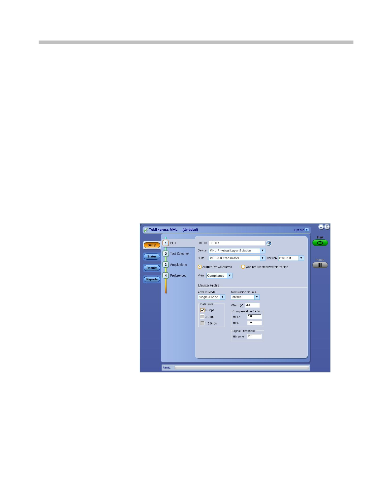
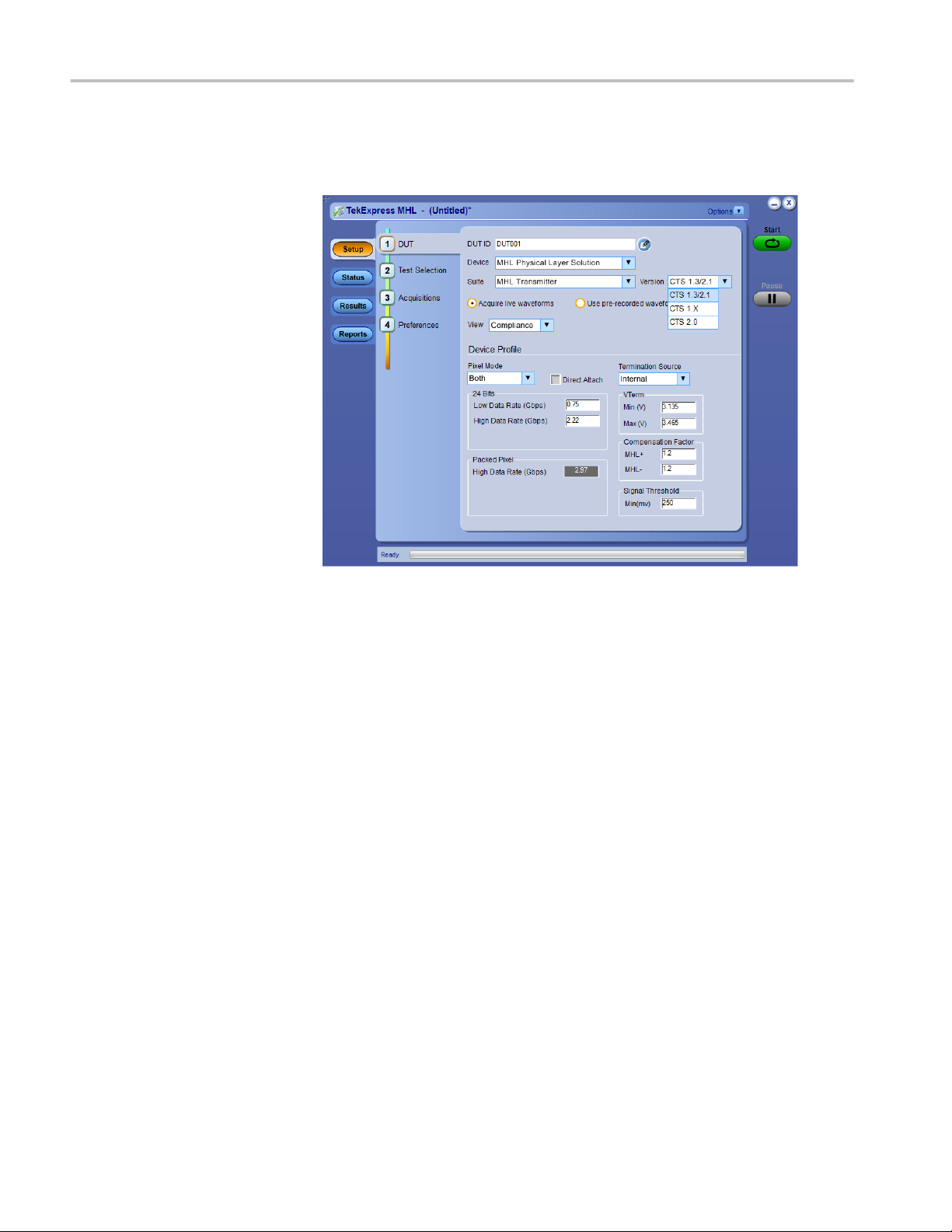
Select the suite and version of the CTS by clicking on the Setup panel and
clicking the DUT tab. See Application basics for more information.
Supported Tests:
TekExpress MHL 3.0 Transmitter supports these automated Data, Clock and
eCBUS tests.
TekExpress MHL 3.0 Receiver supports these automated Sink and Dongle tests.
TekExpress MHL Transmitter supports these automated Clock and Data tests.
TekExpress MHL Receiver supports these automated Sink and Dongle tests.
TekExpress MHL Cables supports these automated Clock and Data tests.
Additional tests may be performed manually by loading the test patterns on the
Tektronix Arbitrary Waveform Generator (AWG).
MHL Cable Assembly Electrical Tests
NOTE. Contact your local Tektronix representative for the MOI of cable tests.
■
Impedance
■
Intra-Pair Skew
■
Delay
■
Insertion Loss
■
Differential and Common Mode Conversion
MHL Printable Online Help 3
Page 18

Overview and key specifications
Supported Resolutions:
See also:
MHL Transmitter supports these resolutions.
MHL Receiver supports these resolutions.
MHL Cables supports these resolutions.
Application basics
Equipment connection setup MHL 3.0 Transmitter
Equipment connection setup MHL 3.0 Receiver
Equipment connection setup MHL Transmitter
Equipment connection setup MHL Receiver
Equipment connection setup MHL Cables
Install the software
Application directories and usage
File name extensions
Supported tests: MHL 3.0 Transmitter
TekExpress MHL 3.0 Transmitter supports the following automated Data, Clock
and eCBUS tests:
These tests are supported for CTS Version 3.3:
MHL 3.0 Transmitter output tests
■
TMDS Data
■
3.7.2.1: Single-ended high level output voltage of differential TMDS data
+/-: V
SE_HIGH_DF_TMDS_DATA
This test confirms that the single-ended high level voltage of the
differential TMDS data output is within the specified limits.
■
3.7.2.2: Single-ended low level output voltage of differential TMDS data
+/-: V
SE_LOW_DF_TMDS_DATA
This test confirms that the single-ended low level voltage of the
differential TMDS data is within the specified limits.
■
3.7.2.5: Differential output swing voltage of differential TMDS data:
V
DF_SWING_DF_TMDS_DATA
This test confirms that the differential swing voltage of the differential
TMDS data is within the specified limits.
■
3.7.2.13: Rise time of differential TMDS data: T
R_DF_TMDS_DATA
This test confirms that the rise time of differential TMDS data is within
the specified limits.
4 MHL Printable Online Help
Page 19

Overview and key specifications
■
3.7.2.14: Fall time of differential TMDS data: T
F_DF_TMDS_DATA
This test confirms that the fall time of differential TMDS data is within
the specified limits.
■
3.7.2.17: Peak-to-peak amplitude of differential TMDS data:
T
PP_TP1_DF_TMDS_DATA
This test confirms that the peak-to-peak amplitude of differential TMDS
data is within the specified limits.
■
3.7.2.27: Differential TMDS data eye diagram at TP2
This test confirms that the differential TMDS data eye diagram is within
the specified limits.
■
MHL Clock
■
3.7.2.7: Single-ended high level output voltage of single-ended MHL
clock data: V
SE_HIGH_SE_MHL_CLK
This test confirms that the single-ended high level voltages of the singleended MHL clock are within the specified limits. This test is applied only
to the DUT with eCBUS-S.
■
3.7.2.8: Single-ended low level output voltage of single-ended MHL
clock data: V
SE_LOW_SE_MHL_CLK
This test confirms that the single-ended low level voltages of the singleended MHL clock are within the specified limits. This test is applied only
to the DUT with eCBUS-S.
■
3.7.2.9: Single-ended output swing voltage of single-ended MHL clock
data: V
SE_SWING_SE_MHL_CLK
This test confirms that the single-ended output swing voltages of the
Single-Ended MHL clock are within the specified limits. This test is
applied only to the DUT with eCBUS-S.
■
3.7.2.20: Single-ended MHL clock frequency: F
SE_MHL_CLK
This test confirms that the single-ended MHL clock frequency is within
the specified limits. This test is applied only to the DUT with eCBUS-S.
■
3.7.2.21: Single-ended MHL clock front porch: T
CFP_SE_MHL_CLK
This test confirms that the single-ended MHL clock front porch time is
within the specified limits. This test is applied only to the DUT with
eCBUS-S.
■
3.7.2.22: Single-ended MHL clock back porth: T
CBP_SE_MHL_CLK
This test confirms that the single-ended MHL clock back porch time is
within the specified limits. This test is applied only to the DUT with
eCBUS-S.
■
3.7.2.23: Rise time of single-ended MHL clock: T
TR_SE_MHL_CLK
MHL Printable Online Help 5
Page 20

Overview and key specifications
This test confirms that the rise time of single-ended MHL clock is within
the specified limits. This test is applied only to the DUT with eCBUS-S.
■
3.7.2.26: Single-ended MHL clock jitter at TP2:
T
CLOCK_JITTER_TP2_SE_MHL_CLK
This test confirms that single-ended MHL clock jitter at TP2 is within the
specified limits. This test is applied only to the DUT with eCBUS-S.
■
MHL eCBUS
■
3.7.2.7: Single-ended high level output voltage of single-ended eCBUS-S
forward data: V
SE_HIHG_SE_eCBUS_FWD
This test confirms that the single-ended high level voltages of the singleended eCBUS-S forward data are within the specified limits. This test is
applied only to the DUT with eCBUS-S.
■
3.7.2.8: Single-ended low level output voltage of single-ended eCBUS-S
forward data: V
SE_LOW_SE_eCBUS_FWD
This test confirms that the single-ended low level voltages of the singleended eCBUS-S forward data are within the specified limits. This test is
applied only to the DUT with eCBUS-S.
■
3.7.2.9: Single-ended output swing voltage of single-ended eCBUS-S
forward data: V
SE_SWING_SE_eCBUS_FWD
This test confirms that the single-ended output swing voltages of the
single-ended eCBUS-S forward data are within the specified limits. This
test is applied only to the DUT with eCBUS-S.
■
3.7.2.24: Fall time of single-ended MHL clock, eCBUS-S forward data:
T
F_SE_eCBUS_CLK
, T
F_SE_eCBUS_FWD
This test confirms that the fall times of single-ended MHL clock and
eCBUS-S forward data are within the specified limits. This test is applied
only to the DUT with eCBUS-S.
■
3.7.2.25: Peak--to-peak amplitude of eCBUS-S forward data:
V
PP_TP1_SE_eCBUS_FWD
This test confirms that the peak-to-peak amplitude of eCBUS-S forward
data is within the specified limits. This test is applied only to the DUT
with eCBUS-S.
■
3.7.2.29: eCBUS-S forward data eye diagram at TP2
This test confirms that the clock jitter of the TMDS differential clock
complies with the limits mentioned in specification.
6 MHL Printable Online Help
Page 21

Overview and key specifications
MHL 3.0 Transmitter input tests
■
MHL eCBUS tests
■
3.7.2.32: Input DC voltage Tolerance of eCBUS-S backward data:
V
IDC_SE_eCBUS_BWD
This test confirms that the source DUT tolerates the input DC voltage
levels of eCBUS-S backward data specified in the specification.
■
3.7.2.36: Jitter tolerance of eCBUS-S backward data
This test confirms that the source DUT tolerates the maximum jitter of
input eCBUS-S backward data specified in the specification.
■
3.7.2.40 Duty Cycle Tolerance of Single-Ended MHLClock - Source
This test confirms that the Source DUT tolerates duty cycle variation of
the input Single-Ended MHL Clock during the eCBUS-S Start-Up
sequence specified in the specification
■
Auto Calibration (for 3.7.2.36 Jitter Tolerance of eCBUS-S BWD Data)
This test confirms that the Nominal Jitter & Error patterns used for
"3.7.2.36 - Jitter tolerance of eCBUS-S backward data" test meets the
required specification.
NOTE.
For Eye diagram test, TekExpress MHL solution uses the Auto mask feature to
automatically place the mask to achieve zero or minimal hits. In case of Mask hit,
Manual mode options permit user to manually place the mask. Refer to the Mask
movement procedure.
TekExpress MHL solution supports only Horizontal movement of mask.
MHL Printable Online Help 7
Page 22

Overview and key specifications
Supported tests: MHL 3.0 Receiver
TekExpress MHL 3.0 Receiver supports the following automated Sink and
Dongle tests.
These tests are supported for CTS Version 3.3:
MHL 3.0 Receiver output tests
■
MHL Sink
■
4.7.2.14: Single-ended high level output voltage of eCBUS-S backward
data: V
This test confirms that the single-ended high level voltage of eCBUS-S
backward data output is within the specified limits.. This test is applied
only to the DUT with eCBUS-S.
■
4.7.2.15: Single-ended low level output voltage of eCBUS-S forward
data: V
This test confirms that the single-ended low level voltage of eCBUS-S
backward data output is within the specified limts. This test is applied
only to the DUT with eCBUS-S.
SE_HIGH_SE_eCBUS_BWD
SE_LOW_SE_eCBUS_BWD
■
4.7.2.16: Single-ended output swing voltage of eCBUS-S backward data:
V
SE_SWING_SE_eCBUS_BWD
This test confirms that the single-ended output swing voltage of eCBUSS backward data output is within the specified limits. This test is applied
only to the DUT with eCBUS-S.
■
4.7.2.20: Rise time of eCBUS-S backward data: T
R_SE_eCBUS_BWD
This test confirms that the rise time of eCBUS-S backward data output is
within the specified limits. This test is applied only to the DUT with
eCBUS-S.
■
4.7.2.21: Fall time of eCBUS-S backward data: T
F_SE_eCBUS_BWD
This test confirms that the fall time of eCBUS-S BWD data output is
within the specified limits. This test is applied only to the DUT with
eCBUS-S.
■
4.7.2.22: Peak-to-peak amplitude of eCBUS-S backward data:
V
PP_TP2_SE_eCBUS_BWD
This test confirms that the peak-to-peak amplitude of eCBUS-S
backward data output is within the specified limits.. This test is applied
only to the DUT with eCBUS-S.
■
4.7.2.24: eCBUS-S backward data eye diagram at TP1
8 MHL Printable Online Help
Page 23

Overview and key specifications
This test confirms that the eCBUS-S backward data eye diagram at TP1
is within the specified limits. This test is applied only to the DUT with
eCBUS-S.
■
MHL Dongle
■
5.7.2.16: Output DC voltage of eCBUS-S backward data:
V
ODC_SE_eCBUS_BWD
This test confirms that the DC voltage level of eCBUS-S backward data
output signal is within the specified limits. This test is applied only to the
DUT with eCBUS-D.
■
5.7.2.17: Single-ended output swing voltage of eCBUS-S backward data:
V
SE_SWING_SE_eCBUS_BWD
This test confirms that the single-ended output swing voltage of eCBUSS backward data output is within the specified limits. This test is applied
only to the DUT with eCBUS-S.
■
5.7.2.19: eCBUS-S backward data eye diagram at TP3
This test confirms that the eCBUS-S backward data eye diagram at TP3
is within the specified limits. This test is applied only to the DUT with
eCBUS-S.
MHL 3.0 Receiver input tests
■
MHL Sink
■
4.7.2.1: Input DC voltage tolerance of differential TMDS data:
V
IDC_DF_TMDS_DATA
This test confirms that the Sink device supports the DC voltage level of
the differential TMDS data input signal allowed by the specification.
■
4.7.2.3: Differential input swing voltage tolerance of differential TMDS
data: V
IDF_SWING_DF_TMDS_DATA
This test confirms that the Sink device supports the differential swing
voltage of the differential TMDS data input signal allowed by the
specification.
■
4.7.2.5: Input DC voltage tolerance of single-ended MHL clock and
eCBUS-S forward data: V
This test confirms that the single-ended MHL clock and eCBUS-S
forward data input signals allowed by the specification. This test is
applied only to the DUT with eCBUS-S.
■
4.7.2.7: Differential intra-pair skew tolerance of differential TMDS data:
T
SKEW_TP2_DF_TMDS_DATA
IDC_SELMHL_CLK
, V
IDC_SE_eCBUS_FWD
This test confirms that the Sink device tolerates the differential intra-pair
skew of the differential TMDS data input signal allowed by the
specification.
■
4.7.2.10: Jitter tolerance of single-ended MHL clock:
T
CLOCK_JITTER_TP2_SE_MHL_CLK
MHL Printable Online Help 9
Page 24

Overview and key specifications
This test confirms that the Sink device tolerates the single-ended MHL
clock jitter. This test is applied only to the DUT with eCBUS-S.
■
4.7.2.28 Duty Cycle Tolerance of Single-Ended MHLClock - Sink
This test confirms that the Sink DUT tolerates duty cycle variation of the
input Single-Ended MHL Clock during the eCBUS-S Start-Up sequence
specified in the specification.
■
MHL Dongle
■
5.7.2.1: Single-ended high level input voltage tolerance of differential
TMDS data: V
SE_HIGH_DF_TMDS_DATA
This test confirms that the Dongle device supports the single-ended high
level voltage of the differential TMDS data input signal allowed by the
specification.
■
5.7.2.2: Single-ended low level input voltage tolerance of differential
TMDS data: V
SE_LOW_DF_TMDS_DATA
This test confirms that the Dongle device supports the single-ended low
level voltage of the differential TMDS data input signal allowed by the
specification.
■
5.7.2.5: Differential input swing voltage tolerance of differential TMDS
data: V
IDF_SWING_DF_TMDS_DATA
This test confirms that the Dongle device supports the differential swing
voltage of the differential TMDS data input signal allowed by the
specification.
■
5.7.2.7: Single-ended high level input voltage tolerance of single-ended
MHL clock and eCBUS-S forward data: V
V
SE_HIGH_SE_eCBUS_FWD
SE_HIGH_SE_MHL_CLK
This test confirms that the Dongle device supports the single-ended high
level voltage of the single-ended MHL clock and eCBUS-S forward data
input signals allowed by the specification. This test is applied only to the
DUT with eCBUS-S.
■
5.7.2.8: Single-ended low level input voltage tolerance of single-ended
MHL clock and eCBUS-S forward data: V
V
SE_LOW_SE_eCBUS_FWD
SE_LOW_SE_MHL_CLK
This test confirms that the Dongle device supports the single-ended low
level voltage of the single-ended MHL clock and eCBUS-S forward data
input signals allowed by the specification. This test is applied only to the
DUT with eCBUS-S.
■
5.7.2.10: Differential intra-pair skew tolerance of differential TMDS
data: T
SKEW_TP3_DF_TMDS_DATA
,
,
This test confirms that the Donge device tolerates the differential intrapair skew of the differential TMDS data input signal allowed by the
specification.
■
5.7.2.13: Jitter tolerance of single-ended MHL clock
10 MHL Printable Online Help
Page 25

Overview and key specifications
This test confirms that the Dongle device tolerates the single-ended MHL
clock jitter and eCBUS-S forward data eye diagram impairments and
differential TMDS data eye diagram impairments allowed by the
specification. This test is applied only to the DUT with eCBUS-S.
■
5.7.2.23 Duty Cycle Tolerance of Single-Ended MHLClock - Dongle
This test confirms that the Dongle device tolerates duty cycle variation of
the input Single-Ended MHL Clock during the eCBUS-S Start-Up
sequence specified in the specification.
Supported tests: MHL Transmitter
TekExpress MHL Transmitter supports the following automated Clock and Data
tests:
These tests are supported for CTS Version 1.0:
Clock tests
■
3.1.1.1: Standby (Off) Output Voltage Test - V
OFF
This test measures that the MHL source output voltage is within the specified
level limits when the source device is in Standby State or power off mode as
specified in the CDF.
■
3.1.1.5: Common-mode Output Swing Voltage Test - V
CMSWING
This test confirms that common-mode output voltage swing amplitude is
within the specified limits when the DUT operates in normal mode.
■
3.1.1.7: Common-mode Rise and Fall Times Test - T
R_CM
, T
F_CM
This test confirms that the rise time and fall time of the common-mode output
signal are within the specified limits.
■
3.1.1.10: MHL Clock Duty Cycle Test - 24 Bit or Packed Pixel Mode
This test confirms that the MHL clock duty cycle in 24-bit or packed pixel
mode does not exceed the limits allowed by the specification.
■
3.1.1.11: MHL Clock Jitter Test
This test confirms that the MHL Clock output does not contain excessive
jitter larger than the limit allowed by the specification.
Data tests
■
3.1.1.2: Single-ended High Level Voltage Test - V
SE_HIGH
This test confirms that the single-ended high output voltage level is within
the specified limits when the DUT is in normal mode.
■
3.1.1.3: Single-ended Low Level Voltage Test - V
SE_LOW
This test confirms that the single-ended low output voltage level is within the
specified limits when the DUT is in normal mode.
■
3.1.1.4: Differential Output Swing Voltage Test - V
DF_SWING
MHL Printable Online Help 11
Page 26

Overview and key specifications
This test confirms that the differential output voltage swing amplitude is
within the specified limits when the DUT is in normal mode.
■
3.1.1.6: Differential Rise and Fall Times Test - T
R_DF
, T
F_DF
This test confirms that the rise and fall times of the differential output signal
are equal to or larger than the minimum limit.
■
3.1.1.8: Differential Intra-Pair Skew Test - T
SKEW_DF
This test confirms that the timing skew in the differential signal pair is below
the specified limits.
■
3.1.1.12: MHL Data Eye Diagram Test
This test confirms that the MHL Data output has signal quality that meets the
eye opening required by the specification.
NOTE.
For Eye diagram test, TekExpress MHL solution uses the Auto mask feature to
automatically place the mask to achieve zero or minimal hits. In case of Mask hit,
Manual mode options permit user to manually place the mask. Refer to the Mask
movement procedure.
TekExpress MHL solution supports only Horizontal movement of mask.
These tests are supported for CTS Version 2.0:
Clock tests
■
3.1.1.1: Standby (Off) Output Voltage Test - V
OFF
This test measures that the MHL source output voltage is within the specified
level limits when the source device is in Standby State or power off mode as
specified in the CDF.
■
3.1.1.5: Common-mode Output Swing Voltage Test - V
CMSWING
This test confirms that common-mode output voltage swing amplitude is
within the specified limits when the DUT operates in normal mode.
■
3.1.1.7: Common-mode Rise and Fall Times Test - T
R_CM
, T
F_CM
This test confirms that the rise time and fall time of the common-mode output
signal are within the specified limits.
■
3.1.1.10: MHL Clock Duty Cycle Test - Normal Mode
This test confirms that the MHL clock duty cycle does not exceed the limits
allowed by the specification in Normal Mode.
■
3.1.1.11: MHL Clock Jitter Test - Normal Mode
This test confirms that the MHL Clock output does not contain excessive
jitter greater than the limit allowed by the specification in Normal Mode.
■
3.1.1.14: MHL Clock Duty Cycle Test - Packed Pixel Mode
12 MHL Printable Online Help
Page 27

Overview and key specifications
This test confirms that the MHL clock duty cycle in packed pixel mode does
not exceed the limits allowed by the specification.
■
3.1.1.15: MHL Clock Jitter Test - Packed Pixel Mode
This test confirms that the MHL Clock output does not contain excessive
jitter larger than the limit allowed by the specification in Packed Pixel Mode.
Data tests
■
3.1.1.2: Single-ended High Level Voltage Test - V
SE_HIGH
This test confirms that the single-ended high output voltage level is within
the specified limits when the DUT is in normal mode.
■
3.1.1.3: Single-ended Low Level Voltage Test - V
SE_LOW
This test confirms that the single-ended low output voltage level is within the
specified limits when the DUT is in normal mode.
■
3.1.1.4: Differential Output Swing Voltage Test - V
DF_SWING
This test confirms that the differential output voltage swing amplitude is
within the specified limits when the DUT is in normal mode.
■
3.1.1.6: Differential Rise and Fall Times Test - T
R_DF
, T
F_DF
This test confirms that the rise and fall times of the differential output signal
are equal to or larger than the minimum limit.
■
3.1.1.8: Differential Intra-Pair Skew Test - T
SKEW_DF
This test confirms that the timing skew in the differential signal pair is below
the specified limits.
■
3.1.1.12: MHL Data Eye Diagram Test - Normal Mode
This test confirms that the MHL Data output has signal quality that meets the
eye opening required by the specification in Normal Mode.
■
3.1.1.16: MHL Data Eye Diagram Test - Packed Pixel Mode
This test confirms that the MHL Data output has signal quality that meets the
eye opening required by the specification in Packed Pixel Mode.
NOTE.
For Eye diagram test, TekExpress MHL solution uses the Auto mask feature to
automatically place the mask to achieve zero or minimal hits. In case of Mask hit,
Manual mode options permit user to manually place the mask. Refer to the Mask
movement procedure.
TekExpress MHL solution supports only Horizontal movement of mask.
These tests are supported for CTS Version 1.3/2.1:Clock Tests
■
3.1.1.1: Standby (Off) Output Voltage Test - V
OFF
MHL Printable Online Help 13
Page 28

Overview and key specifications
This test measures that the MHL source output voltage is within the specified
level limits when the source device is in Standby State or power off mode as
specified in the CDF.
■
3.1.1.5: Common-mode Output Swing Voltage Test - V
CMSWING
This test confirms that common-mode output voltage swing amplitude is
within the specified limits when the DUT operates in normal mode.
■
3.1.1.7: Common-mode Rise and Fall Times Test - T
R_CM
, T
F_CM
This test confirms that the rise time and fall time of the common-mode output
signal are within the specified limits.
■
3.1.1.10: MHL Clock Duty Cycle Test - Normal Mode
This test confirms that the MHL clock duty cycle does not exceed the limits
allowed by the specification in Normal Mode.
■
3.1.1.14: MHL Clock Duty Cycle Test - Packed Pixel Mode
This test confirms that the MHL clock duty cycle in packed pixel mode does
not exceed the limits allowed by the specification.
■
3.1.1.17: TP2 Clock Jitter Test - Normal Mode
This test confirms that the TP2 Clock output does not contain excessive jitter
larger than the limit allowed by the specification in Normal Mode.
■
3.1.1.19: TP2 Clock Jitter Test - Packed Pixel Mode
This test confirms that the TP2 Clock output does not contain excessive jitter
larger than the limit allowed by the specification in Packed Pixel Mode.
Data tests
■
3.1.1.2: Single-ended High Level Voltage Test - V
SE_HIGH
This test confirms that the single-ended high output voltage level is within
the specified limits when the DUT is in normal mode.
■
3.1.1.3: Single-ended Low Level Voltage Test - V
SE_LOW
This test confirms that the single-ended low output voltage level is within the
specified limits when the DUT is in normal mode.
■
3.1.1.4: Differential Output Swing Voltage Test - V
DF_SWING
This test confirms that the differential output voltage swing amplitude is
within the specified limits when the DUT is in normal mode.
■
3.1.1.6: Differential Rise and Fall Times Test - T
R_DF
, T
F_DF
This test confirms that the rise and fall times of the differential output signal
are equal to or larger than the minimum limit.
■
3.1.1.18: TP2 Data Eye Diagram Test - Normal Mode
This test confirms that the TP2 Data output has signal quality that meets the
eye opening required by the specification in Normal Mode.
■
3.1.1.20: TP2 Data Eye Diagram Test - Packed Pixel Mode
14 MHL Printable Online Help
Page 29

Overview and key specifications
This test confirms that the TP2 Data output has signal quality that meets the
eye opening required by the specification in Packed Pixel Mode.
NOTE.
For Eye diagram test, TekExpress MHL solution uses the Auto mask feature to
automatically place the mask to achieve zero or minimal hits. In case of Mask hit,
Manual mode options permit user to manually place the mask. Refer to the Mask
movement procedure.
TekExpress MHL solution supports only Horizontal movement of mask.
Supported tests: MHL Receiver
TekExpress MHL Receiver supports the following automated Sink and Dongle
tests.
These tests are supported for CTS version 1.0:
MHL Sink tests
■
4.1.1.1: Input Signal DC Voltage Level Tolerance Test
This test confirms that the Sink device supports input signal DC voltage level
allowed by the specification.
■
4.1.1.2: Input Signal Minimum and Maximum Swing Voltages Tolerance
Test
This test confirms that the Sink device supports input signal DC voltage level
and swing voltage allowed by the specification.
■
4.1.1.3: Intra Pair Skew Tolerance Test
This test confirms that the Sink device can tolerate the maximum intra-pair
skew allowed by the specification.
■
4.1.1.4: Jitter Tolerance Test
This test confirms that the Sink device can tolerate the maximum clock and
data jitter amounts allowed by the specification.
MHL Dongle tests
■
5.1.1.1: Input Signal Single-Ended Voltage Level Tolerance Test
This test confirms that the Dongle device supports input signal single-ended
voltage level allowed by the specification.
■
5.1.1.2: Input Signal Minimum and Maximum Swing Voltages Tolerance
Test
This test confirms that the Dongle device supports input signal minimum and
maximum swing voltages allowed by the specification.
■
5.1.1.3: Intra-Pair Skew Tolerance Test
MHL Printable Online Help 15
Page 30

Overview and key specifications
This test confirms that the Dongle device can tolerate the maximum intra-pair
skew allowed by the specification.
■
5.1.1.4: Jitter Tolerance Test
This test confirms that the Dongle device can tolerate the maximum clock
and data jitter amounts allowed by the specification.
These tests are supported for CTS version 2.0 and version 1.3/2.1:
MHL Sink tests
■
4.1.1.1: Input Signal DC Voltage Level Tolerance Test
This test confirms that the Sink device supports input signal DC voltage level
allowed by the specification.
■
4.1.1.2: Input Signal Minimum and Maximum Swing Voltages Tolerance
Test
This test confirms that the Sink device supports input signal DC voltage level
and swing voltage allowed by the specification.
■
4.1.1.3: Intra Pair Skew Tolerance Test
This test confirms that the Sink device can tolerate the maximum intra-pair
skew allowed by the specification.
■
4.1.1.4: Jitter Tolerance Test in Normal Mode
This test confirms that the Sink device can tolerate the maximum clock and
data jitter amounts allowed by the specification in Normal Mode with cable
emulator.
■
4.1.1.8: Jitter Tolerance Test – Packed Pixel Mode
This test confirms that the Sink device can tolerate the maximum clock and
data jitter amounts allowed by the specification in Packed Pixel Mode.
MHL Dongle tests
■
5.1.1.1: Input Signal Single-Ended Voltage Level Tolerance Test
This test confirms that the Dongle device supports input signal single-ended
voltage level allowed by the specification.
■
5.1.1.2: Input Signal Minimum and Maximum Swing Voltages Tolerance
Test
This test confirms that the Dongle device supports input signal minimum and
maximum swing voltages allowed by the specification.
■
5.1.1.3: Intra-Pair Skew Tolerance Test
This test confirms that the Dongle device can tolerate the maximum intra-pair
skew allowed by the specification.
■
5.1.1.4: Jitter Tolerance Test – Normal Mode
16 MHL Printable Online Help
Page 31

Overview and key specifications
This test confirms that the Dongle device can tolerate the maximum clock
and data jitter amounts allowed by the specification in Normal Mode.
■
5.1.1.9: Jitter Tolerance Test – Packed Pixel Mode
This test confirms that the Dongle device can tolerate the maximum clock
and data jitter amounts allowed by the specification in Packed Pixel Mode.
NOTE. All sink tests are applicable for CTS 1.3 / 2.1 direct attach device.
Supported tests: MHL Cables
TekExpress MHL Cables supports the following automated Clock and Data tests.
These tests are supported for CTS Version 1.3/2.1:
MHL Clock tests
■
7.2.1.16: Minimum clock swing test
This test confirms that minimum clock voltage swing amplitude is within the
specified limits allowed by the specification.
MHL Data tests
■
7.2.1.17: MHL eye diagram test
This test confirms that the MHL data cable output has signal quality that
meets the eye opening required by the specification.
NOTE.
For Eye diagram test, TekExpress MHL solution uses the Auto mask feature to
automatically place the mask to achieve zero or minimal hits. In case of Mask hit,
Manual mode options permit user to manually place the mask. Refer to the Mask
movement procedure.
TekExpress MHL solution supports only Horizontal movement of mask.
MHL Printable Online Help 17
Page 32

Overview and key specifications
Supported tests: MHL Receiver Protocol
TekExpress MHL Receiver Protocol supports the following automated Sink and
Dongle tests for CTS 1.X, 2.0, 1.3/2.1 versions.
MHL Sink Protocol tests based on the AWG direct synthesis patterns
These tests confirm that the sink DUT synchronizes if the data stream provides
only minimum length Control Periods.
■
4.2.1.1: Character Synchronization in Normal mode
■
4.2.1.3: Character Synchronization in Packed Pixel mode
CTS 2.0, CTS 1.3/2.1 only.
These tests confirm that the sink DUT accepts all valid packet types.
■
4.2.1.2: Packet Types in Normal Mode
■
4.2.1.4: Packet Types in Packed Pixel Mode
CTS 2.0, CTS 1.3/2.1 only.
These tests verify that the sink DUT supports the video formats with no
distortion.
■
4.2.2.1: Video Formats in Normal Mode
■
4.2.2.4: Video Formats in Packed Pixel Mode
CTS 2.0, CTS 1.3/2.1 only.
This test verifies that the sink supports RGB, YCbCr, 4:2:2 pixel encoding in
Normal mode.
■
4.2.2.2: Pixel Encoding in Normal Mode
This test verifies that the sink has the correct QY and QS bits in the Video
Capability Data Block, and the Sink displays with no distortion.
■
4.2.2.3: Video Quantization Range
This test verifies that the sink supports the required Audio formats and
reproduces audio properly.
■
4.2.3.1: IEC 60958 / IEC61937
This test verifies that the sink properly regenerates audio when different Audio
Clock Regeneration parameters are used.
■
4.2.3.2: Audio Clock Regeneration
These tests confirm that the sink DUT supports the required and optional 3D
video modes.
■
4.2.8.2: 3D Video Format in Normal Mode
CTS 2.0, CTS 1.3/2.1 only.
■
4.2.8.3: 3D Video Format in Packed Pixel Mode
CTS 2.0, CTS 1.3/2.1 only.
18 MHL Printable Online Help
Page 33

Overview and key specifications
MHL Dongle Protocol tests based on AWG direct synthesis patterns
This test confirms that the dongle DUT synchronizes if the data stream provides
only minimum length Control Periods.
■
5.2.1.1: Character Synchronization in Normal mode
■
5.2.1.3: Character Synchronization in Packed Pixel mode
CTS 2.0, CTS 1.3/2.1 only.
These tests confirm that the dongle DUT accepts all valid packet types.
■
5.2.1.2: Packet Types in Normal Mode
■
5.2.1.4: Packet Types in Packed Pixel Mode
CTS 2.0, CTS 1.3/2.1 only.
These tests verify that the dongle DUT supports the video formats with no
distortion.
■
5.2.2.1: Video Formats in Normal Mode
■
5.2.2.4: Video Formats in Packed Pixel Mode
CTS 2.0, CTS 1.3/2.1 only.
This test confirms that the dongle supports RGB, YCbCr, 4:2:2 pixel encoding in
Normal mode.
■
5.2.2.2: Pixel Encoding in Normal Mode
This test verifies that the dongle has correct QY and QS bits in the Video
Capability Data Block, and the dongle displays with no distortion.
■
5.2.2.3: Video Quantization Range
This test verifies that the dongle converts audio properly.
■
5.2.3.1: IEC 60958 / IEC61937
This test verifies that the dongle properly regenerates audio when different Audio
Clock Regeneration parameters are used.
■
5.2.3.2: Audio Clock Regeneration
These tests confirm that the dongle DUT supports the required and optional 3D
video modes.
■
5.2.8.2: 3D Video Format in Normal Mode
CTS 2.0, CTS 1.3/2.1 only.
■
5.2.8.3: 3D Video Format in Packed Pixel Mode
CTS 2.0, CTS 1.3/2.1 only.
MHL Printable Online Help 19
Page 34

Overview and key specifications
Supported data rate: MHL 3.0 Transmitter
CTS 3.2: All of the TekExpress MHL tests can be performed for DUTs operating
in data between 6Gbps and 1.5Gbps. For instance, a DUT could have any of the
following:
Low: 1.5Gbps High: 6 Gbps
Low: 1.5Gbps High: 3 Gbps
Low: 3Gbps High: 6 Gbps
NOTE. When date rate selected is one only, then Low and High data rate are the
same and software performs the test at selected data rate.
Supported data rate: MHL 3.0 Receiver
CTS 3.3: All of the TekExpress MHL tests can be performed for DUTs operating
at these data rates (Gbps):
■
6Gbps
■
3Gbps
■
1.5Gbps
Supported resolutions: MHL Transmitter
CTS 1.0: All of the TekExpress MHL tests can be performed for DUTs operating
in resolutions between 25 MHz and 74.25 MHz. Other resolutions that fall within
this range can be entered in the Low Resolution and High Resolution fields on
the DUT tab of the Setup panel. For instance, a DUT could have any of the
following:
Low : 25 High : 25
Low : 25 High : 27
Low : 25 High : 74.25
When Low and High resolutions are the same, the software performs the test at
that one resolution.
CTS 2.0, CTS 1.3/2.1: All of the TekExpress MHL tests can be performed for
DUTs operating at these data rates (Gbps):
24 Bit mode:
Low : 0.75 High : 2.22
Low : 0.81 High : 2.22
Packed Pixel mode:
20 MHL Printable Online Help
Page 35

Overview and key specifications
Low : 2.97 High : 2.97
Other data rates that fall within this range can be entered in the Low Data Rate
and High Data Rate fields on the DUT tab of the Setup panel.
Table 1: Supported resolutions (Transmitter)
Test group Test name Supported resolutions
MHL Clock 3.1.1.1: Standby Output Voltage – V
3.1.1.5: Common-mode Output Swing Voltage
V
CMSWING
3.1.1.7: Common-mode Rise and Fall TimesT
, T
R_CM
F_CM
CTS 1.X
3.1.1.10: MHL Clock Duty Cycle – 24 Bit or
Packed Pixel Mode
CTS 2.0
3.1.1.10: MHL Clock Duty Cycle – Normal Mode
CTS 1.X
3.1.1.11: MHL Clock Jitter
CTS 2.0
3.1.1.11: MHL Clock Jitter – Normal Mode
CTS 2.0
3.1.1.14: MHL Clock Duty Cycle – Packed Pixel
Mode
CTS 2.0
3.1.1.15: MHL Clock Jitter – Packed Pixel Mode
CTS 1.3 / 2.1
3.1.1.17: TP2 Clock Jitter Test - Normal Mode
CTS 1.3 / 2.1
3.1.1.19: TP2 Clock Jitter Test - Packed Pixel
Mode
OFF
—
Low resolution
High resolution
High resolution
High resolution
Low and High resolutions
Low and High resolutions
High resolution (PP)
High resolution (PP)
Low and High resolutions
High resolution (PP)
MHL Printable Online Help 21
Page 36

Overview and key specifications
Test group Test name Supported resolutions
MHL Data 3.1.1.2: Single-ended High Level Voltage –
V
SE_HIGH
3.1.1.3: Single-ended Low Level Voltages –
V
SE_LOW
3.1.1.4: Differential Output Swing Voltage –
V
DF_SWING
3.1.1.6: Differential Rise and Fall Times – T
T
F_DF
3.1.1.8: Differential Intra-Pair Skew – T
CTS 1.X, CTS 2.0
3.1.1.12: MHL Data Eye Diagram
CTS 2.0
3.1.1.12: MHL Data Eye Diagram – Normal Mode
CTS 2.0
3.1.1.16: MHL Data Eye Diagram – Packed Pixel
Mode
CTS 1.3 / 2.1
3.1.1.18: TP2 Data Eye Diagram Test - Normal
Mode
CTS 1.3 / 2.1
3.1.1.20: TP2 Data Eye Diagram Test - Packed
Pixel Mode
SKEW_DF
Low resolution
Low resolution
Low resolution
,
High resolution
R_DF
Low resolution
Low and High resolutions
Low and High resolutions
High resolution (PP)
Low and High resolutions
High resolution (PP)
Supported resolutions: MHL Receiver
CTS 1.X: All of the TekExpress MHL Receiver tests can be performed for DUTs
operating in resolutions of 25, 27 and 74.25 MHz according to the standard.
Other resolutions that fall within this range can be entered in the Low Resolution
and High Resolution fields on the DUT tab of the Setup panel. Either of the
Resolutions can be High according to the Manufacturer. For instance, a DUT
could have any of the following:
Low : 25 High : 25
Low : 25 High : 27
Low : 25 High : 74.25
CTS 2.0 and CTS 1.3 / 2.1: All of the TekExpress MHL tests can be performed
for DUTs operating at these data rates (Gpbs):
24 Bit mode:
Low : 0.75 High : 2.22
Low : 0.81 High : 2.22
Packed Pixel mode:
22 MHL Printable Online Help
Page 37

Overview and key specifications
Low : 2.97 High : 2.97
Other data rates that fall within this range can be entered in the Low Data Rate
and High Data Rate fields on the DUT tab of the Setup panel.
Table 2: Supported resolutions (MHL Receiver)
Test group Test name Supported resolutions
MHL Sink 4.1.1.1: Input Signal DC Voltage Level
Tolerance
4.1.1.2: Input Signal Minimum and Maximum
Swing Voltages Tolerance
4.1.1.3: Intra-Pair Skew Tolerance Highest
CTS 1.X
4.1.1.4: Jitter Tolerance
CTS 2.0 and CTS 1.3 / 2.1
4.1.1.4: Jitter Tolerance in Normal Mode
CTS 2.0 and CTS 1.3 / 2.1
4.1.1.8: Jitter Tolerance in Packed Pixell Mode
MHL Dongle CTS 2.0 and CTS 1.3 / 2.1
5.1.1.1: Input Signal Single-Ended Voltage Level
Tolerance
5.1.1.2: Input Signal Minimum and Maximum
Swing Voltage Tolerance
5.1.1.3: Intra-Pair Skew Tolerance Highest
CTS 1.X
5.1.1.4: Jitter Tolerance
CTS 2.0 and CTS 1.3 / 2.1
5.1.1.4: Jitter Tolerance in Normal Mode
CTS 2.0 and CTS 1.3 / 2.1
5.1.1.9: Jitter Tolerance in Packed Pixel Mode
Highest
Highest
Lowest and Highest
Highest
Highest
Highest
Lowest and Highest
Highest
MHL Printable Online Help 23
Page 38

Overview and key specifications
Supported resolutions: MHL Cables
CTS 1.3/2.1: All of the TekExpress MHL tests can be performed for DUTs
operating at these data rates (Gbps):
Packed Pixel mode:
Low : 2.97 High : 2.97
Table 3: Supported resolutions (Cables)
Test group Test name Supported resolutions
MHL Clock 7.2.1.16: MHL Minimum Clock Swing Test High (PP) resolution
MHL Data 7.2.1.17: MHL Cable Data Eye Diagram High (PP )resolution
Supported resolutions: MHL Receiver Protocol
The following MHL Receiver Protocol resolutions are supported for all CTS
versions, unless noted otherwise.
24 MHL Printable Online Help
Page 39

Overview and key specifications
Table 4: Supported resolutions (MHL Receiver Protocol)
Test group Test name Supported resolutions
MHL Sink 4.2.1.1: Character Synchronization 720x576p
720x480p
4.2.1.2: Packet Types in Normal
mode
CTS 2.0 and CTS 1.3 / 2.1
4.2.1.3: Character Synchronization in
Packed Pixel Mode
CTS 2.0 and CTS 1.3 / 2.1
4.2.1.4: Packet Types in Packed
Pixel mode
4.2.2.1: Video Formats in Normal
mode
4.2.2.2: Pixel Encoding in Normal
mode
4.2.2.3: Video Quantization Range 720x576p
CTS 2.0 and CTS 1.3 / 2.1
4.2.2.4: Video Formats in Packed
Pixel mode
CTS 2.0 and CTS 1.3 / 2.1
4.2.8.2: 3D Video Formats in Normal
mode
CTS 2.0 and CTS 1.3 / 2.1
4.2.8.3: 3D Video Formats in Packed
Pixel mode
4.2.3.1: Audio Test IEC 60958 /
IEC61937
4.2.3.2: Audio Clock Regeneration 720x576p
720x576p
720x480p
640x480p
1920x1080p
1920x1080p
2880x576i
1920x1080p, 1920x1080i
1440x576p, 1440x576i
1440x480i
1280x720p
720x480p
640x480p
720x576p
720x480p
720x480p
1920x1080p
1920x1080p, 1920x1080i
1280x720p
1920x1080p
1280x720p
720x576p
720x480p
720x480p
MHL Printable Online Help 25
Page 40

Overview and key specifications
Test group Test name Supported resolutions
MHL Dongle 5.2.1.1: Character Synchronization 720x576p
720x480p
CTS 2.0 and CTS 1.3 / 2.1
5.2.1.2: Packet Types in Normal
mode
CTS 2.0 and CTS 1.3 / 2.1
5.2.1.3: Character Synchronization in
Packed Pixel mode
CTS 2.0 and CTS 1.3 / 2.1
5.2.1.4: Packet Types in Packed
Pixel mode
5.2.2.1: Video Formats in Normal
mode
5.2.2.2: Pixel Encoding in Normal
mode
5.2.2.3: Video Quantization Range 720x576p
CTS 2.0 and CTS 1.3 / 2.1
5.2.2.4: Video Formats in Packed
Pixel mode
CTS 2.0 and CTS 1.3 / 2.1
5.2.8.2: 3D Video Formats in Normal
mode
CTS 2.0 and CTS 1.3 / 2.1
5.2.8.3: 3D Video Formats in Packed
Pixel mode
5.2.3.1: Audio Test IEC 60958 /
IEC61937
5.2.3.2: Audio Clock Regeneration 720x576p
720x576p
720x480p
640x480p
1920x1080p
1920x1080p
2880x576i
1920x1080p, 1920x1080i
1440x576p, 1440x576i
1440x480i
1280x720p
720x480p
640x480p
720x576p
720x480p
720x480p
1920x1080p
1920x1080p, 1920x1080i
1280x720p
1920x1080p
1280x720p
720x576p
720x480p
720x480p
26 MHL Printable Online Help
Page 41

Operating basics
Equipment connection setup using the TF-MHL-CBS2-SOSI (MHL transmitter and receiver)
The Source Sink board (TF-MHL-CBS2-SOSI) is a low cost alternative to the CBus Analyzer. It provides an alternative solution for setup and can be used for the
following:
■
Source tests, electrical – 3.1.1.1 to 3.1.1.20 (excluding 3.1.1.13)
■
Source System tests – 3.2.2.1 to 3.2.2.3 ; 3.2.3.1 to 3.2.3.4 ;
3.2..1.12 (excluding 3.1.1.13)
■
Sink tests, electrical – 4.1.1.1 to 4.1.1.8 (excluding 4.1.1.7)
■
Sink system test – 4.2.1.1 to 4.2.1.2 ; 4.2.2.1 to 4.2.2.3; 4.2.3.1 to 4.2.3.2
■
Dongle tests, electrical - 5.1.1.1 to 5.1.1.9 (excluding 5.1.1.7, 5.1.1.8)
■
Dongle System tests - 5.2.1.1 to 5.2.1.2 ; 5.2.2.1 to 5.2.2.3; 5.2.3.1 to 5.2.3.2
NOTE. The low cost TF-MHL-CBS2-SOSI cannot be used for C-Bus tests 3.3.x.x
and 4.3.x.x.
Figure 1: Low cost Source Sink board (TF-MHL-CBS2-SOSI)
MHL Printable Online Help 27
Page 42

Operating basics
TF-MHL-CBS2-SOSI setup
for source testing
Figure 2: TF-MHL-CBS2-SOSI acting as a sink for source testing
TF-MHL-CBS2-SOSI setup
for sink testing
Figure 3: TF-MHL-CBS2-SOSI acting as a source for sink testing
28 MHL Printable Online Help
Page 43

Operating basics
Equipment connection setup (MHL 3.0 Transmitter)
You need the following equipment to run MHL Transmitter tests. (For details,
see Minimum system requirements):
■
A supported Tektronix oscilloscope
■
Two or three differential probes – P7313SMA, for single ended and
differential tests
■
Device-under-test (DUT)
■
Wilder/Tektronix fixtures
■
TCA-SMA adapter (Not required if third probe used is P7313SMA)
■
P7240 probe
■
C-Bus Sink boards
■
MHL Signal generator: AWG7122C for eCBUS source
Connection diagrams and the tests they apply to are listed below.
Table 5: MHL 3.0 Transmitter Output tests
Connection diagram 1
TMDS Data
3.7.2.1: Single-ended high level output voltage of differential TMDS data+/-:
V
SE_HIGH_DF_TMDS_DATA
3.7.2.2 Single-ended low level output voltage of differential TMDS data+/-: V
3.7.2.5 Differential output swing voltage of differential TMDS data: V
3.7.2.13 Rise time of differential TMDS data: T
3.7.2.14 Fall time of differential TMDS data: T
3.7.2.17 Peak-to-peak amplitude of differential TMDS data: V
R_DF_TMDS_DATA
F_DF_TMDS_DATA
PP_TP1_DF_TMDS_DATA
3.7.2.27 TMDS data eye diagram
MHL Clock
3.7.2.7 Single-ended high level output voltage of single-ended MHL clock data:
V
SE_HIGH_SE_MHL_CLK
3.7.2.8 Single-ended low level output voltage of single-ended MHL clock data:
V
SE_LOW_SE_MHL_CLK
3.7.2.9 Single-ended output swing voltage of single-ended MHL clock data: V
3.7.2.20 Single-ended MHL clock frequency: F
3.7.2.21 Single-ended MHL clock front porch: T
3.7.2.22 Single-ended MHL clock back porch: T
3.7.2.23 Rise time of single-ended MHL clock: T
3.7.2.26 Single-ended MHL clock jitter at TP2: T
SE_MHL_CLK
CFP_SE_MHL_CLK
CBP_SE_MHL_CLK
R_SE_MHL_CLK
CLOCK_JITTER_TP2_SE_MHL_CLK
MHL eCBUS
3.7.2.7 Single-ended high level output voltage of single-ended MHL clock and eCBUS-S forward
data: V
SE_HIGH_SE_eCBUS_FWD
SE_LOW_DF_TMDS_DATA
DF_SWING_DF_TMDS_DATA
SE_SWING_SE_MHL_CLK
MHL Printable Online Help 29
Page 44

Operating basics
Connection diagram 1
3.7.2.8 Single-ended low level output voltage of eingle-ended MHL clock and eCBUS-S forward
data: V
SE_LOW_SE_eCBUS_FWD
3.7.2.9 Single-ended output swing voltage of single-ended MHL clock and eCBUS-S forward data:
V
SE_SWING_SE_eCBUS_FWD
3.7.2.24 Fall time of single-ended MHL clock and eCBUS-S forward data: V
T
F_SE_eCBUS_FWD
3.7.2.25 Peak-to-peak smplitude of eCBUS-S forward data: V
PP_TP1_SE_eCBUS_FWD
3.7.2.29 eCBUS-S forward data eye diagram at TP2
F_SE_MHL_CLK
,
Table 6: MHL 3.0 Transmitter Input tests
Connection diagram 2
MHL eCBUS
3.7.2.32: Input DC voltage tolerance of eCBUS-S backward data: V
IDC_SE_eCBUS_BWD
3.7.2.36: Jitter tolerance of eCBUS-S backward data
3.7.2.40 Duty Cycle Tolerance of Single-Ended MHLClock - Source
30 MHL Printable Online Help
Page 45

Operating basics
Connection diagram 2
MHL Printable Online Help 31
Page 46

Operating basics
Connection diagram 2
Figure 4: Transmitter Input for 70K
32 MHL Printable Online Help
Page 47

Operating basics
Connection diagram 3
Auto Calibration (for 3.7.2.36 Jitter Tolerance of eCBUS-S BWD Data)
MHL Printable Online Help 33
Page 48

Operating basics
Connection diagram 3
Figure 5: Transmitter Input - Calibration for 70K
34 MHL Printable Online Help
Page 49

Operating basics
See Also
Equipment connection setup MHL 3.0 Receiver
Equipment connection Setup MHL Receiver
Equipment connection setup MHL Cables
About algorithms
View connected instruments
Equipment connection setup (MHL 3.0 Receiver)
You need the following equipment (for details, see Minimum system
requirements):
■
A supported Tektronix oscilloscope
■
Two or three differential probes – P7313SMA, for single ended and
differential tests
■
Device-under-test (DUT)
■
Wilder fixtures
■
TCA-SMA adapter (Not required if third probe used is P7313SMA)
■
C-Bus Sink boards
■
MHL Signal generator: AWG7122C for eCBUS source with AWG70002A
or AWG7122C for AV_Link
Connection diagrams and the tests they apply to are listed below.
Table 7: MHL 3.0 Receiver Output tests
Connection diagram 4
MHL Sink
4.7.2.14: Single-ended high level output voltage of eCBUS-S backward data:
V
SE_HIGH_SE_eCBUS_BWD
4.7.2.15: Single-ended low level output voltage of eCBUS-S forward data: V
4.7.2.16: Single-ended output swing voltage of eCBUS-S backward data:
V
SE_SWING_SE_eCBUS_BWD
4.7.2.20: Rise time of eCBUS-S backward data: T
4.7.2.21: Fall time of eCBUS-S backward data: T
4.7.2.22: Peak-to-peak amplitude of eCBUS-S backward data: V
4.7.2.24: eCBUS-S backward data eye diagram at TP1
MHL Dongle
5.7.2.16: Output DC voltage of eCBUS-S backward data: V
5.7.2.17: Single-ended output swing voltage of eCBUS-S backward data:
V
SE_SWING_SE_eCBUS_BWD
5.7.2.19: eCBUS-S backward data eye diagram at TP3
R_SE_eCBUS_BWD
F_SE_eCBUS_BWD
PP_TP2_SE_eCBUS_BWD
ODC_SE_eCBUS_BWD
SE_LOW_SE_eCBUS_BWD
MHL Printable Online Help 35
Page 50

Operating basics
Connection diagram 4
36 MHL Printable Online Help
Page 51

Operating basics
Connection diagram 4
Figure 6: Receiver Output for 70k
Table 8: MHL 3.0 Receiver Input tests
Connection diagram 5
MHL Sink
4.7.2.1: Input DC voltage tolerance of differential TMDS data: V
IDC_DF_TMDS_DATA
4.7.2.3: Differential input swing voltage tolerance of differential TMDS data:
V
IDF_SWING_DF_TMDS_DATA
MHL Printable Online Help 37
Page 52

Operating basics
Connection diagram 5
4.7.2.5: Input DC voltage tolerance of single-ended MHL clock and eCBUS-S forward data:
V
IDC_SE_MHL_CLK
4.7.2.10: Jitter tolerance of single-ended MHL clock: T
4.7.2.28 Duty Cycle Tolerance of Single-Ended MHLClock - Sink
MHL Dongle
5.7.2.1: Single-ended high level input voltage tolerance of differential TMDS data:
VSE_HIGH_DF_TMDS_DATA
5.7.2.2: Single-ended low level input voltage tolerance of differential TMDS data:
VSE_LOW_DF_TMDS_DATA
5.7.2.5: Differential input swing voltage tolerance of differential TMDS data:
V
IDF_SWING_DF_TMDS_DATA
5.7.2.7: Single-ended high level input voltage tolerance of single-ended MHL clock and eCBUS-S
forward data: V
5.7.2.8: Single-ended low level input voltage tolerance of single-ended MHL clock and eCBUS-S
forward data: V
5.7.2.23 Duty Cycle Tolerance of Single-Ended MHLClock - Dongle
MHL Sink
4.7.2.7: Differential intra-pair skew tolerance of differential TMDS data: T
MHL Dongle
5.7.2.10: Differential intra-pair skew tolerance of differential TMDS data: T
5.7.2.13: Jitter tolerance of single-ended MHL clock, eCBUS-S forward data and differential TMDS
data
, V
IDC_SE_eCBUS_FWD
SE_HIGH_SE_MHL_CLK
SE_LOW_SE_MHL_CLK
, V
SE_HIGH_SE_eCBUS_FWD
, V
SE_LOW_SE_eCBUS_FWD
CLOCK_JITTER_TP2_SE_MHL_CLK
SKEW_TP2_DF_TMDS_DATA
SKEW_TP3_DF_TMDS_DATA
38 MHL Printable Online Help
Page 53

Connection diagram 5
Operating basics
MHL Printable Online Help 39
Page 54

Operating basics
Connection diagram 5
Figure 7: Receiver Input for 70K
40 MHL Printable Online Help
Page 55

Operating basics
See Also
Equipment connection setup MHL 3.0 Transmitter
Equipment connection setup MHL Transmitter
Equipment connection setup MHL Cables
About algorithms
View connected instruments
Equipment connection setup (MHL Transmitter)
You need the following equipment to run MHL Transmitter tests. (For details,
see Minimum system requirements):
■
A supported Tektronix oscilloscope
■
Two differential probes – P7313SMA, for single ended and differential tests
■
One single ended probe – Probe P7240 for common mode tests
■
Device under test (DUT)
■
Wilder/Tektronix fixtures
■
C-Bus Sink boards
Clock and Data Tests
Connection diagrams and the tests they apply to are listed below.
Connection diagram 1 (Transmitter)
3.1.1.4: Differential output swing voltage Test - V
3.1.1.5: Common-mode output swing voltage Test - V
3.1.1.6: Differential rise and fall times test -T
3.1.1.7: Common-mode rise and fall times test -T
3.1.1.10: MHL Clock duty cycle test – normal mode
3.1.1.11: MHL Clock jitter test – normal mode
3.1.1.12: MHL Data eye diagram test – normal mode
3.1.1.14: MHL Clock duty cycle test – packed pixel mode
3.1.1.15: MHL Clock jitter test – packed pixel mode
R_DF
DF_SWING
CMSWING
, T
F_DF
, T
R_CM
F_CM
MHL Printable Online Help 41
Page 56

Operating basics
Connection diagram 1 (Transmitter)
3.1.1.16: MHL Data eye diagram test in packed pixel mode
Connection diagram 2 (Transmitter)
3.1.1.2 Single-ended high level voltage — VSE_HIGH
3.1.1.3 Single-ended low level voltages — VSE_LOW
3.1.1.8: Differential intra-pair skew test - T
SKEW_DF
3.1.1.17 TP2 Clock jitter — normal Mode
3.1.1.18 TP2 Eye diagram — normal Mode
3.1.1.19 TP2 Clock jitter — packed pixel Mode
3.1.1.20 TP2 Eye diagram — packed pixel Mode
42 MHL Printable Online Help
Page 57

Operating basics
Connection diagram 3 (Transmitter)
3.1.1.1 Standby output voltage — V
OFF
See Also
Equipment connection setup MHL Receiver
Equipment connection setup MHL Cables
About algorithms
View connected instruments
MHL Printable Online Help 43
Page 58

Operating basics
Equipment connection setup (MHL Receiver protocol and MHL protocol)
You need the following equipment (for details, see Minimum system
requirements):
■
A supported Tektronix oscilloscope
■
One differential probe – P7313SMA
■
Device under test (DUT)
■
Wilder fixtures
■
C-Bus Sink boards
■
MHL Signal generator: AWG7122B/C with option 01 and 02 or 06 and 08
Connection diagrams and the tests they apply to are listed below.
Sink tests
Sink tests
4.1.1.1: Input signal DC voltage level tolerance
4.1.1.3: Intra-pair skew tolerance
CTS 1.X
4.1.1.4: Jitter tolerance
CTS 2.0, CTS 1.3 / 2.1
4.1.1.4: Jitter tolerance in normal mode
CTS 2.0, CTS 1.3 / 2.1
4.1.1.8: Jitter tolerance in packed pixel mode
4.2.1.1: Character synchronization
CTS 2.0, CTS 1.3 / 2.1
4.2.1.3: Character synchronization in packed pixel mode
4.2.1.2: Packet types in normal node
CTS 2.0, CTS 1.3 / 2.1
4.2.1.4: Packet types in packed pixel node
4.2.2.1: Video formats in normal mode
CTS 2.0, CTS 1.3 / 2.1
4.2.2.4: Video formats in packed pixel mode
4.2.2.2: Pixel encoding in normal mode
4.2.2.3: Video quantization range
CTS 2.0, CTS 1.3 / 2.1
4.2.8.2: 3D Video format in normal mode
CTS 2.0, CTS 1.3 / 2.1
4.2.8.3: 3D Video format in packed pixel mode
4.2.3.1: IEC 60958 / IEC61937
4.2.3.2: Audio clock regeneration
44 MHL Printable Online Help
Page 59

Operating basics
Sink tests
Sink-MHL Input Signal DC Voltage Level Test
MHL Printable Online Help 45
Page 60

Operating basics
Sink tests
Single-Ended Signals Calibration Setup for Sink Test
Differential and Common-Mode Signals Calibration Setup for Sink Test
46 MHL Printable Online Help
Page 61

Operating basics
Sink tests
4.1.1.2: Input signal minimum and maximum swing voltages tolerance:
Sink — MHL Input Signal DC Voltage Level Min-Max Test
Amplifier Connections to Power Supply
MHL Printable Online Help 47
Page 62

Operating basics
Sink tests
Single Ended Signals Calibration Setup for Sink Min-Max Test
Differential and Common-Mode Signals Calibration Setup for Sink Min-Max Test
48 MHL Printable Online Help
Page 63

Operating basics
Dongle tests
Dongle tests
5.1.1.1: Input signal single-ended voltage level tolerance
5.1.1.3: Intra-pair skew tolerance test
CTS 1.X
5.1.1.4: Jitter tolerance
CTS 2.0
5.1.1.4: Jitter tolerance in normal mode
CTS 2.0
5.1.1.9: Jitter tolerance in packed pixel mode
5.2.1.1: Character synchronization
CTS 2.0, CTS 1.3 / 2.1
5.2.1.3: Character synchronization in packed pixel mode
5.2.1.2: Packet types in normal mode
CTS 2.0, CTS 1.3 / 2.1
5.2.1.4: Packet types in packed pixel mode
5.2.2.1: Video formats in normal mode
CTS 2.0, CTS 1.3 / 2.1
5.2.2.4: Video formats in packed pixel mode
5.2.2.2: Pixel encoding in normal mode
5.2.2.3: Video quantization range
CTS 2.0, CTS 1.3 / 2.1
5.2.8.2: 3D Video format in normal mode
CTS 2.0, CTS 1.3 / 2.1
5.2.8.3: 3D Video format in packed pixel mode
5.2.3.1: IEC 60958 / IEC61937
5.2.3.2: Audio clock regeneration
MHL Printable Online Help 49
Page 64

Operating basics
Dongle tests
Dongle — Input Signal Single-Ended Voltage level Tolerance Test
50 MHL Printable Online Help
Page 65

Operating basics
Dongle tests
Single-Ended Signals Calibration Setup for Dongle Test
Differential and Common-Mode Signals Calibration Setup for Dongle Test
MHL Printable Online Help 51
Page 66

Operating basics
Dongle tests
5.1.1.2: Input signal minimum and maximum swing voltage tolerance
Dongle Min-Max Setup
Amplifier Connections to DC Power Supply
52 MHL Printable Online Help
Page 67

Operating basics
Dongle tests
Single-Ended Signals Calibration Setup for Dongle Min Max Test
Differential and Common-Mode Signals Calibration Setup for Dongle Min Max Test
MHL Printable Online Help 53
Page 68

Operating basics
See Also
Equipment connection setup MHL Transmitter
Equipment connection setup MHL Cables
About algorithms
View connected instruments
Equipment connection setup (MHL Cables)
You need the following equipment to run MHL Cables tests. (For details, see
Minimum system requirements):
■
A supported Tektronix oscilloscope
■
Two differential probes – P7313SMA, for single ended and differential tests
■
One single ended probe – P7240 for common mode tests
■
Device under test (DUT)
■
Wilder/Tektronix fixtures
■
C-Bus source boards
■
MHL Signal generator: AWG7122B/C with option 01 and 02 or 06 and 08
Connection diagrams and the tests they apply to are listed below.
54 MHL Printable Online Help
Page 69

Operating basics
Clock and Data Tests
Connection diagram 1 (Cables)
7.2.1.16: Minimum clock swing test
7.2.1.17: Eye diagram test
Single-Ended Signals Calibration Setup for Cable Tests
Differential & Common-Mode Signals Calibration Setup for Cable Tests
MHL Printable Online Help 55
Page 70

Operating basics
Connection diagram 1 (Cables)
Cable – Minimum Clock Swing Test / Eye Diagram Test Setup
See Also
Equipment connection setup MHL Transmitter
Equipment connection setup MHL Receiver
About algorithms
View connected Instruments
56 MHL Printable Online Help
Page 71

Operating basics
Application directories and usage
The application directory and associated files are organized as follows:
The following table lists the default directory names and their usage.
Table 9: Application directories and usage
Directory names Usage
InstallDir\TekExpress\TekExpress MHL Contains the application and associated files
TekExpress MHL\ACP Contains instrument and MHL application-
specific interface libraries
TekExpress MHL\Bin Contains miscellaneous MHL application
libraries
TekExpress MHL\Compliance Suites Contains compliance-specific files and filter files
TekExpress MHL\Data Manager Contains result management-specific libraries of
the MHL application
TekExpress MHL\Data Storage Contains libraries needed for storing data
TekExpress MHL\Documents Contains the technical documentation for the
MHL application
TekExpress MHL\Examples Contains various support files
TekExpress MHL\ICP Contains instrument and MHL application-
specific interface libraries
TekExpress MHL\Lib Contains utility files specific to the MHL
application
TekExpress MHL\Report Generator Contains style sheets for report generation
TekExpress MHL\SCP Contains instrument and MHL application-
specific interface libraries
TekExpress MHL\Tools Contains instrument and MHL application-
specific files
MHL Printable Online Help 57
Page 72

Operating basics
See Also
View test-related files
View test-related files
Files related to MHL tests are stored in the MHL folder under the My
TekExpress shared folder. In the MHL folder, each test setup has a test setup file
and a test setup folder, both with the test setup name. The test setup file is
preceded by the MHL icon and usually has no file extension displayed.
Inside the test setup folder is another folder named for the DUT ID used in the
test sessions (the default is DUT001).
Inside the DUT001 folder are the session folders and files. Each session has a
folder and file pair, both named for the test session using the naming convention
(date)_(time). Each session file is stored outside of its matching session folder.
Each session folder contains image files of any plots generated by the test
session, and any waveform files if prerecorded waveform files were used during
the session.
The first time you run a new, unsaved session, the session files are stored in the
Untitled Session folder located at ..\My TekExpress\MHL. Once you name and
save the session, the Untitled Session folder name is changed to the one you
specified.
NOTE. By default, test report files are saved in the session folder. You can change
the report file location for a specific test.
58 MHL Printable Online Help
Page 73

Operating basics
See Also
File name extensions
File name extensions
The TekExpress MHL software uses the following file name extensions:
File name extension Description
.TekX Session files are saved in this format but the
extensions may not be displayed
.py The test sequence file
.xml The encrypted XML file that contains the test-
specific configuration information
The log file extension is also xml
.wfm The test waveform file
.mht Test result reports are saved in this format by
default. Test reports can also be saved in
MHTML format.
.flt Filter file used with transmitter tests
See Also
Application directories and usage
MHL Printable Online Help 59
Page 74

Operating basics
60 MHL Printable Online Help
Page 75

Getting started
Installing the software
Compatibility
Minimum system
requirements
The TekExpress Suite MHL 3.0 Transmitter and MHL 3.0 Receiver of version
CTS 3.3 application runs on the following Tektronix oscilloscopes:
■
DPO/DSA/MSO71254C,DPO/DSA/MSO71604C, DPO/DSA/MSO72004C,
DPO/DSA72504D, DPO/DSA73304D Digital Oscilloscopes with Option
DJA.
■
DPO/MSO72304Dx, DPO/MSO72504Dx, DPO/MSO73304Dx Digital
Oscilloscopes with Option DJA.
The TekExpress Suite MHL Transmitter, MHL Receiver, MHL Cable test and
MHL Receiver protocol of version CTS 1.x, 2.0, 1.3/2.1 application runs on the
following Tektronix oscilloscopes:
■
DPO/DSA/MSO70804C, DPO/DSA/MSO71254C, DPO/DSA/MSO71604C,
DPO/DSA/MSO72004C, DPO/DSA72504D, DPO/DSA73304D Digital
Oscilloscopes with Option DJA.
■
DPO/MSO72304Dx, DPO/MSO72504Dx, DPO/MSO73304Dx Digital
Oscilloscopes with Option DJA.
See Also. Minimum system requirements
The following table shows the minimum system requirements for an oscilloscope
to run TekExpress.
Table 10: System requirements
Component Minimum requirement
Oscilloscope BW ≥ 12.5 GHz for MHL 3.0 Advanced Analysis
and Compliance Software (Needs Option MHD).
BW ≥ 12.5 GHz with Opt 20XL for MHL 1.x/
2.0 and CTS 2.1 Protocol Analysis software.
BW ≥ 8 GHz for MHL 1.x, 2.0, and
1.3/2.1 Advanced Analysis and Compliance
Software (Needs Option DJA).
For a list of compatible oscilloscopes, see
Compatibility.
Processor Same as the oscilloscope
Operating system Same as the oscilloscope
Memory Same as the oscilloscope
MHL Printable Online Help 61
Page 76

Getting started
Component Minimum requirement
Hard disk Same as the oscilloscope
Display Same as the oscilloscope
Software
■
TekExpress MHL Advanced Analysis and
Compliance software.
■
DPOJET, Jitter and Eye Diagram Analysis
Tool Ver 7.0.0.416 for Windows 7 Scopes.
■
Microsoft Internet Explorer 6.0 SP1 or later.
■
Microsoft Photo Editor 3.0 or equivalent
software for viewing image files.
■
Adobe Reader 8.0 or equivalent software
for viewing portable document format (PDF)
files.
1
Probes
MHL sources
MHL 3.0 sources
TDR tests
■
Two Differential Probes – P7313SMA for
Single-Ended and Differential tests.
■
One Differential Probe – P7240 for
Common-Mode tests.
■
MHL Tx DUTs
■
One AWG7122 C with Option 01,
02/06 and 08 which can be used as an
MHL DUT
■
MHL Ref waveforms
■
MHL 3.0 Tx DUTs
Either
■
AWG7122C with Option 01 and 02 or
06 and 08 or
■
AWG70002A with option 01, 3, 225
which can be used as an MHL 3.0 DUT
■
MHL 3.0 Ref waveforms
■
Oscilloscope – DSA8200 or equivalent with
80E03 and 80E04 modules and I-Connect
software
1
If TekExpress is running on an instrument having a video resolution lower than 800 x 600 (for example, sampling
oscilloscope), it is recommended that you connect a secondary monitor, which must be enabled before launching the
application.
62 MHL Printable Online Help
Page 77

Getting started
Component Minimum requirement
MHL Generator for Sink and Dongle and
Cable tests
■
AWG7122C with option 01 and 02 or
06 and 08 or AWG7002A with option
01,03,225
MHL 3.0 Generator for Sink and Dongle and
Cable tests
■
Signal generators should be AWG7122C
for eCBUS Source with AWG70002A or
AWG7122C for AV_Link
MHL fixtures MHL fixture kits from Tektronix
■
TF-MHL-TPA-TEK (Complete MHL Fixture
kit)
■
TF-MHL-TPA-TEK-SO (Source Fixture
Only kit)
■
TF-MHL-TPA-TEK-SI (Sink Fixture kit)
■
TF-MHL-TPA-TEK-DG (Dongle Adopter kit)
■
TF-MHL-TPA-TEK-CB (MHL Cable Adopter
kit)
MHL 3.0 fixtures MHL 3.0 fixture kits from Tektronix
■
TF-MHL3-TPA-KIT
TF-MHL3-TPA-KIT contains one TF-MHL-TPASOS-MUSB
2
and one TF-MHL-TPA-SOSIS-
HDM
2
Two numbers are required for 3.7.2.6 Auto Calibration test measurement
MHL Printable Online Help 63
Page 78

Getting started
Component Minimum requirement
MHL accessory kit (to be used with Tektronix
AWG)
TF-MHL-DS-Acckit from Tektronix contains the
following:
■
Two Bias Tees from Mini-Circuits –
ZX85-12G-S+
■
Two Amplifiers from Pico Second Pulse
Labs – 5866 (needed only for Sink/Dongle
Min/Max test)
■
Two 120PS TTC filters from Pico Second
Pulse Labs – 5915-100-120PS
Install the software
Other devices
■
Microsoft compatible mouse or compatible
pointing device
■
Four USB ports (two USB ports minimum)
■
PCI-GPIB or equivalent interface for
instrument connectivity.
■
2 pair of SMA cables
3
See Also. Compatibility
The software can be installed on any compatible instrument running Windows 7.
1. Close all applications (including the TekScope application).
2. Go to the www.tek.com Web site and search for MHL to locate the
installation file. Download the file MHL WebInstaller.exe.
3. Double-click the executable file to extract the installation files. After
extraction, the installer launches and displays the InstallShield Wizard.
■
Check TekExpress application for MHL to install the TekExpress MHL
application.
4. The software automatically installs in the following location:
■
Windows 7 location: C:\Program Files (x86)\Tektronix\TekExpress
\TekExpress MHL
5. The installer updates the TekScope Analyze menu to include TekExpress
MHL:
3
If TekExpress is installed on a Tektronix oscilloscope, the virtual GPIB port will be used by TekExpress for
communicating with oscilloscope applications. If external GPIB communication devices such as USB-GPIB-HS or
equivalent are used for instrument connectivity, ensure that the Talker Listener utility is enabled in the DPO/DSA
oscilloscope's GPIB menu. For ease of use, connect to an external (secondary) monitor.
64 MHL Printable Online Help
Page 79

Getting started
Activate the license
See Also. Minimum system requirements
Compatibility
Activate the license using the option installation wizard on the oscilloscope.
Follow these steps to activate the TekExpress MHL license:
MHL Printable Online Help 65
Page 80

Getting started
1. From the oscilloscope menu bar, click Utilities > Option Installation.
The TekScope Option Installation wizard opens.
View version and license
information
2. Instructions for using the Options Installation window to activate licenses for
installed applications is provided in the oscilloscope online help. Press the F1
key on the oscilloscope keyboard to open the Option Installation help topic.
Follow the directions in the topic to activate the license.
See Also. View version and license information
Use the following instructions to view application version information and
version information for the application modules such as the Programmatic
Interface and the Programmatic Interface Client.
66 MHL Printable Online Help
Page 81

To view version information:
1. From the Options menu, select About TekExpress.
To view license information:
1. From the oscilloscope Help menu, select About TekScope.
Getting started
Starting the software
Start the application
The Options section in the dialog box displays a list of installed options,
including TekExpress MHL.
2. To view the Option key, look in the Option Installation Key section. When
finished, click OK to close the dialog box.
See Also. Activate the license
Options menu
The first time you open the application after installation, you are required to enter
a license key. The application also checks for a file called Resources.xml located
in the My TekExpress folder. If this file is not found, instrument discovery is
performed before launching TekExpress MHL. The Resources.xml file contains
information regarding instruments available on your network.
NOTE. When the application starts, it checks for the appropriate license key. If
the valid license key is not present, the application switches to the Evaluation
mode. If the application fails to detect the key, it continues to run in Evaluation
mode. You are allowed 10 free trials in Evaluation mode. Each time you open the
application without supplying a valid license key, one of the free trials is used.
To run the MHL application, from the TekScope menu, select Analyze >
TekExpress MHL.
MHL Printable Online Help 67
Page 82

Getting started
While running the application, you can switch between the oscilloscope screen
and MHL by clicking the desired window. To keep the application window on
top, select Keep On Top from the Options menu.
NOTE. If the application was not terminated properly during the last use, a dialog
box asks to recall the previously unsaved session.
68 MHL Printable Online Help
Page 83

Getting started
Options menu
Options menu. The Options menu is located in the upper right corner of the
application.
It has the following selections:
Menu Function
Default Test Setup Opens an untitled test setup with defaults
selected
Open Test Setup Opens a saved test setup
Save Test Setup Saves the current test setup selections
Save Test Setup As Creates a new test setup based on an existing
one
Open Recent Displays a menu of recently opened test setups
to select from
Instrument control settings Shows the list of instruments connected to the
test setup and allows you to locate and refresh
connections to connected instruments
Keep On Top Keeps the TekExpress MHL application on top
of other open windows on the desktop
Email settings Use to configure email options for test run and
results notifications
Help Displays TekExpress Help
About TekExpress
■
Displays application details such as
software name, version number, and
copyright
Options Menu
■
Provides access to license information for
your MHL installation
■
Provides a link to the Tektronix Web site
MHL Printable Online Help 69
Page 84

Getting started
Instrument Control Settings
The Instrument Control Settings dialog box shows the list of resources found on
different connections. It serves two purposes:
■
Discovers the connected instruments
■
Confirms the instrument connection setup
Use the Instrument Control Settings feature to search for and view connected
instruments and view instrument connection details. Connected instruments
displayed here can be selected for use in the Global Settings section of the Setup
panel’s Configuration section.
See Also
Options menu
Email Settings
Use the Email Settings utility to configure email notifications if you want the
application to notify you when a tests completes or produces an error. Select the
type of test run information to be included in the notification, such as test reports
and test logs, the email message format, and the email message size limit.
70 MHL Printable Online Help
Page 85

Options menu
Getting started
View connected
instruments: the
instrument control
settings
Use the Instrument Control Settings dialog box to view or search for connected
instruments required for the tests. The application uses TekVISA to discover the
connected instruments.
To refresh the list of connected instruments:
1. From the Options menu, select Instrument control settings.
2. In the Search Criteria section of the Instrument Control Settings dialog box,
select the connection types of the instruments to search for.
MHL Printable Online Help 71
Page 86

Getting started
Instrument search is based on the VISA layer but different connected cables
determine the resource type, such as LAN, GPIB, USB. For example, if you
choose LAN, you can search for all the instruments supported by TekExpress
that are communicating over the LAN. If the search does not find any
instruments that match a selected resource type, a message appears telling
you that no such instruments were found. Click OK to close the message
window.
3. Click Refresh. TekExpress searches for connected instruments.
4. After discovery, the dialog box lists the instrument-related details based on
the search criteria you selected. For example, if you selected LAN and GPIB
as the search criteria, the application checks for the availability of
instruments over LAN, then GPIB.
The details of the instruments are displayed in the Retrieved Instruments table.
The time and date of instrument refresh is displayed in the Last Updated field.
See Also. Equipment connection setup (MHL Transmitter)
Equipment connection setup (MHL Receiver)
Application controls
Equipment connection setup (MHL Cables)
Table 11: Application controls descriptions
Item Description
Options menu Opens the Options menu for access to global
controls
Panels Visual frames with sets of related options. Some
panels are further divided into tabs and other
sections.
Start button
Use the Start button to continuously acquire and
accumulate measurements. If prior acquired
measurements have not been cleared, the new
measurements are added to the existing set.
Stop button
Use the Stop button to abort a test in progress.
Pause \ Continue button
Use the Pause button to interrupt the current
acquisition. When a test is paused, the button
name changes to Continue.
72 MHL Printable Online Help
Page 87

Getting started
Item Description
Clear button
Available only on the Results panel.
Use the Clear button to clear all existing
measurement results. Note that adding or
deleting a measurement, or changing a
configuration parameter of an existing
measurement also clears measurements. This
is to prevent the accumulation of measurement
statistics or sets of statistics that are not
coherent.
Application window move icon
Place the cursor over the three-dot pattern in
the upper left corner of the application window.
When the cursor changes to a hand, drag the
window to the desired location.
Exit the application
Use the following method to exit the application:
NOTE. Using other methods to exit the application results in abnormal
termination of the application.
1.
Click
on the application title bar.
2. Do one of the following:
■
A message box appears asking if you really want to exit TekExpress. To
exit, click Yes. Otherwise, click No.
■
If you have an unsaved session or test setup open, you will be asked if
you want to save it before exiting. To save it, click Yes. If you do not
wish to save, click No. To remain in the session, click Cancel.
MHL Printable Online Help 73
Page 88

Getting started
74 MHL Printable Online Help
Page 89

Application basics
Application basics
The TekExpress MHL software user interface is intuitive and easy to use. In
addition to the UI, a programmatic interface is available.
The user interface has four main panels whose options differ depending upon
Suite selected from the following list:
■
■
■
■
■
■
The following steps explains application basics:
MHL 3.0 Transmitter
MHL 3.0 Receiver
MHL Transmitter
MHL Receiver
MHL Cable
MHL Receiver protocol
See Also
■
First, set up the tests.
■
Then, prepare to run the tests.
■
Then, run the tests and view the progress of analysis.
■
Then, view the results of the tests.
■
You can configure and view reports.
■
You can save and recall test setups.
Overview and key specifications
MHL Printable Online Help 75
Page 90

Application basics
76 MHL Printable Online Help
Page 91

Setting up tests
Setting up tests: the Setup panel
The Setup panel guides you through the MHL test setup process using tabs. The
options selected in a tab affect the options available in the following tab. The
available options differ depending on options selected under Suite and Version
tab.
Setup Panel
NOTE. A check mark next to a tab title means you have made changes. However,
if you make changes on a tab that significantly affects a previous tab, the check
mark of the affected tab is replaced with its number, indicating that you should
check the settings on that tab.
■
DUT tab
Here, you can Specify the DUT ID, device, applications suite (MHL
3.0 Transmitter/MHL 3.0 Receiver/MHL Transmitter/Receiver/MHL Cable),
the CTS version, the view and device profile settings. These settings apply to
all tests for the current session, and affect the test list in the Test Selection
tab.
■
Test selection tab
Here, Select tests individually or by group, view a short description of a
selected test, and view a schematic showing appropriate device connections.
MHL Printable Online Help 77
Page 92

Setting up tests
■
Acquisitions tab (MHL 3.0 Transmitter, MHL 3.0 Receiver, MHL
Transmitter and MHL Cable Test only)
View configurations for attached probes, view a list of signals and sources,
and view the Acquisitions table.
■
Configuration tab (Displays only when View: Advanced is selected in the
DUT tab.)
Here, Select either Compliance Mode or User Defined Mode, view Global
Settings, select measurement settings, and view or edit test parameter limits.
■
Preferences tab
Here, you may specify that an email be sent to you upon test completion.
Preferences tab
78 MHL Printable Online Help
Page 93

Setting up tests
See also
Saving a test setup
Run test and view progress on the Status panel
Viewing test results the results panel
Configuring and viewing reports the reports panel
Select the device parameters on the DUT tab
1. Click the DUT on the Setup panel
Specify the DUT ID, Device, Suite (MHL 3.0 Transmitter/ MHL
3.0 Receiver/ MHL Transmitter/ MHLReceiver/ MHL Cable), CTS version,
View, Acquisition method and Device Profile settings. These settings apply
to all current tests, and affect the test list in the Test Selection tab.
2. Enter the device ID: The default value is DUT001. This ID appears on test
reports. To add comments to the top of a report, click
256 characters.
3. Select Suite: Scroll down and select Suite from the following list.
■
MHL 3.0 Transmitter
and enter up to
■
MHL 3.0 Receiver
■
MHL Transmitter
■
MHL Receiver
■
MHL Cable
■
MHL Receiver protocol
4. Select Version: Version choice determines which Device Profile options
appear on the screen, and which tests appear on the Test Selection tab.
CTS 1.X, CTS 2.0, or CTS 1.3/2.1 version test selection measurements will
be displayed when Suite selection is either MHL Transmitter, MHL
Receiver, MHL Cable or MHL Receiver protocol.
CTS 3.2 version test selection measurements will be displayed when Suite
selection is MHL 3.0 Transmitter or MHL 3.0 Receiver Suite.
5. Select Waveform type : Select either “Acquire Live Waveforms” or “Use
pre-recorded waveform files” for testing. If the suite selection is MHL
Receiver, only pre-recorded waveform measurement option is available.
MHL Printable Online Help 79
Page 94

Setting up tests
6. Select View: Select either Compliance or Advanced. If the suite selection is
MHL Receiver, only compilance view is supported.
■
If you select the Advanced view, an additional Configuration tab
appears.
■
To access configuration options for Compliance view, click the
Configure button on the Test Selection tab.
7. Set the Device Profile options (again, these will differ depending upon the
CTS version selected above).
■
MHL 3.0 Transmitter only: If you select Version CTS 3.3, you will see
this DUT screen.These Device profile options will be available.
DUT tab - CTS 3.3 (MHL 3.0 Transmitter)
Table 12: Device Profile options for CTS 3.0 (MHL 3.0 Transmitter)
Setting Option Description
eCBUS mode Single-ended Single ended eCBUS mode.
Data rate 6 GBPS Select high and low data rate.
3 GBPS
1 GBPS
Termination source Internal Select this if the termination
voltage control mode is INT
(Internal).
External other Select this if the termination
voltage control mode is EXT
(External) and you are using an
external power supply.
80 MHL Printable Online Help
Page 95

Setting up tests
Setting Option Description
VTerm (v) 3.3 Value must be greater than or
equal to (≥) 1 V and less than
or equal to (≤) 5 V.
MHL+ compensation factor 1.0 Used for fixture compensation.
Value should be between 1 and
2.
Default value of MHL+
Compensation factor is 1.0.
MHL- compensation factor 1.0 Used for fixture compensation.
Value should be between 1 and
2.
Default value of MHLCompensation factor is 1.0.
Single threshold Min(mv) 250 Used for signal validation.
Value should be between
50 and 600 mV.
■
MHL 3.0 Receiver only: If you select Version CTS 3.3, you will see this
DUT screen.These Device profile options will be available.
DUT tab - CTS 3.3 (MHL 3.0 Receiver)
MHL Printable Online Help 81
Page 96

Setting up tests
Table 13: Device Profile options for CTS 3.0 (MHL 3.0 Receiver)
Setting Option Description
Data Rate 6 GBPS Select the highest data rate
3 GBPS
1.5 GBPS
Refresh Rate 60Hz Select this if the DUT refresh
■
MHL Transmitter only: If you select Version CTS 1.X, you will see this
supported by the DUT.
rate is 60 Hz.
DUT screen. These Device Profile options will be available.
DUT tab – CTS 1.X (Transmitter)
Table 14: Device Profile options for CTS 1.X (Transmitter)
Setting Option Description
Pixel Mode 24 Bits This is the only option available.
Low Resolution (MHz) 25 Enter a value from 25 to 100.
High Resolution (MHz) 74.25
Low Resolution value should be
less than or equal to High
Resolution, and High
Resolutions should be greater
than or equal to Low resolution.
82 MHL Printable Online Help
Page 97

Setting up tests
Setting Option Description
Num of Other Resolutions 0 If the DUT can support more
than the three standard
resolutions, enter the number
here. Value can be from 0 to
10. Applicable tests will be run
for the number of other
resolutions specified here.
MHL+ Compensation Factor 1.2 Used for fixture compensation.
Value should be between 1 and
2.
MHL– Compensation Factor 1.2 Used for fixture compensation.
Value should be between 1 and
2.
Min Signal Threshold 250 Used for signal validation.
Value should be between
50 and 600 mV.
Termination Source Internal Select this if the termination
voltage control mode is INT
(Internal).
External Other Select this if the termination
voltage control mode is EXT
(External) and you are using an
external power supply.
VTerm Min (V) 3.135 Value must be greater than or
equal to (≥) 1V and less than or
equal to (≤) VTerm Max.
VTerm Max (V) 3.465 Value must be greater than or
equal to (≥) VTerm Min, and
less than or equal to (≤) 5V.
■
MHL Transmitter only: If you select Version CTS 2.0, the DUT screen
and Device Profile options you will see will differ depending upon the
Pixel Mode selected. This screen shows the DUT tab with pixel mode of
both. These Device profile options will be available.
MHL Printable Online Help 83
Page 98

Setting up tests
DUT tab – CTS 2.0 with Pixel Mode of Both (Transmitter)
Table 15: Device Profile options for CTS 2.0 (Transmitter)
Setting Option Description
Pixel Mode 24 Bits Select this if the DUT uses
24 Bit mode.
Packed Pixel Select this if the DUT uses
packed pixel mode.
Both Select this if the DUT uses both
24 Bit and packed pixel mode.
When Pixel Mode is 24 Bits:
Low Data Rate (Gbps) 0.75 Enter a value from 0.75 –
High Data Rate (Gbps) 2.22
Num of Other Data Rates 0 If the DUT can support more
When Pixel Mode is Packed
Pixel:
2.22 Gbps.
Low Data Rate value should be
less than or equal to High Data
Rate and High Data Rate
values should be greater than
or equal to Low Data Rate.
than the three standard
resolutions, enter the number
here. Value can be from 0 to
10. Applicable tests will be run
for the number of other
resolutions specified here.
84 MHL Printable Online Help
Page 99

Setting up tests
Setting Option Description
Low Data Rate (Gbps) 2.25 Enter a value from 2.25 –
High Data Rate (Gbps) 2.97
Num of Other Data Rates 0 If the DUT can support more
When Pixel Mode is Both:
24 Bits:
Low Data Rate (Gbps) 0.75 Enter a value from 0.75 –
High Data Rate (Gbps) 2.22
Packed Pixel:
High Data Rate (Gbps) 2.97 Low Data Rate value should be
MHL+ Compensation Factor 1.2 Used for fixture compensation.
MHL– Compensation Factor 1.2 Used for fixture compensation.
Min Signal Threshold 250 Used for signal validation.
Termination Source Internal Select this if the termination
External Other Select this if the termination
VTerm Min (V) 3.135 Value must be greater than or
2.97 Gbps.
Low Data Rate value should be
less than or equal to High Data
Rate and High Data Rate
values should be greater than
or equal to Low Data Rate.
than the three standard
resolutions; enter the number
here. Value can be from 0 to
10. Applicable tests will be run
for the number of other
resolutions specified here.
2.22 Gbps.
Low Data Rate value should be
less than or equal to High Data
Rate and High Data Rate
values should be greater than
or equal to Low Data Rate.
less than or equal to High Data
Rate and High Data Rate
values should be greater than
or equal to Low Data Rate.
Value should be between 1 and
2.
Value should be between 1 and
2.
Value should be between
50 and 600 mV.
voltage control mode is INT
(Internal).
voltage control mode is EXT
(External) and you are using an
external power supply.
equal to (≥) 1V and less than or
equal to (≤) VTerm Max.
MHL Printable Online Help 85
Page 100

Setting up tests
Setting Option Description
VTerm Max (V) 3.465 Value must be greater than or
equal to (≥) VTerm Min, and
less than or equal to (≤) 5V.
Direct Attach (Applicable for
CTS 1.3 / 2.1 only)
■
MHL Transmitter only: If you select Version CTS 1.3 / 2.1, the DUT
Check / Uncheck Select the checkbox when you
are testing Direct Attach
Device.
screen and Device Profile options you will see will differ depending upon
the Pixel Mode selected. This screen shows this DUT tab screen. These
Device profile options will be available.
DUT tab – CTS 1.3 / 2.1 (Transmitter)
Table 16: Device Profile options for CTS 1.3 / 2.1 (Transmitter)
Setting Option Description
Pixel Mode 24 Bits Select this if the DUT uses
24 Bit mode.
Packed Pixel Select this if the DUT uses
packed pixel mode.
Both Select this if the DUT uses both
24 Bit and packed pixel mode.
When Pixel Mode is 24 Bits:
86 MHL Printable Online Help
 Loading...