

Page 1

xx
TekExpress®D-PHY
ZZZ
Automated Solution
Printable Online Help
*P077051403*
077-0514-03
Page 2

Page 3

TekExpress®D-PHY
Automated Solution
ZZZ
PrintableOnlineHelp
www.tektronix.com
077-0514-03
Page 4

Copyright © Tektronix. All rights reserved. Licensed software products are owned by Tektronix or its
subsidiaries or suppliers, and are protected by national copyright laws and international treaty provisions.
Tektronix products are covered by U.S. and foreign patents, issued and pending. Information in this
publication supersedes that in all previously published material. Specifications and price change privileges
reserved.
TEKTRONIX and TEK are registered trademarks of Tektronix, Inc.
TekExpress is a registered trademark of Tektronix, Inc.
MIPI is a registered trademark of MIPI Alliance.
TekExpress D-PHY Automated Solution Online Help, 076-0227-03.
Contacting Tektronix
Tektronix, Inc.
14150 SW
P.O . Box 500
Beaverton, OR 97077
USA
For product information, sales, service, and technical support:
In Nor
Worldwide, visit www.tektronix.com to find contacts in your area.
Karl Braun Drive
th America, call 1-800-833-9200.
Page 5

Table of Contents
Introduction to the Application
Related Documentation ............... ................................ ................................ ............. 1
Conventions ................................ ................................ ................................ ......... 1
Technical Support ......... ................................ ................................ ......................... 2
Getting Started
Compatib
Minimum System Requirements....................... .................................. ......................... 3
Install the Software ............................ ................................ .................................. ... 4
Application Directories and Usage .... .................................. ................................ ......... 5
Folder Structure..................................................................................................... 6
File Name Extensions .............................................................................................. 7
Activate the License................................... ................................ ............................. 7
Before You Click Run.............................................................................................. 9
ility..... .... . .... . .... .... . .... . .... ..... ... . . .... ..... ..... .... . .... . .... .... . .... . .... ..... ... . . .... . .... 3
Table of Contents
Operating Basics
D-PHY Application Overview ............................... .................................. .................. 11
Starting the Application....................................... ................................ .................... 12
Resizing the Application Window........... ................................ .................................. .. 13
Exiting the Application .... . .... .... . .... . .... ..... .... . .... ..... ... . . .... . .... ..... .... . .... . .... .... . .... . .... .. 13
Global Controls .................................. ................................ ................................ .. 14
Menus ............................. .................................. ................................ ................ 14
File Menu........ ................................ .................................. ............................ 14
View Menu ...... ................................ ................................ .............................. 15
Tools Menu .................................................................................................... 15
Help Menu..................................................................................................... 17
How To
Select Test(s) ............. ................................ .................................. ........................ 19
Configure and Run the Test(s).......................................... .................................. ........ 23
Typical Configuration Parameters ................... ................................ ............................ 28
View and Select Connected Instruments ...................... .................................. ................ 30
Acquire Live Waveform for Analysis. ................................ ................................ .......... 31
Use Prerecorded Waveforms for Analysis ...... ................................ ................................ 33
View the Progress of Analysis ................. ................................ ................................ .. 35
View the Report.................................................................................................... 37
View Test Related Files............... ................................ ................................ ............ 38
TekExpress D-PHY Automated Solution i
Page 6

Table of Contents
Application Examples
Connection Setup ................................ ................................ ................................ .. 40
Configuring Parameter Values.......... .................................. ................................ ........ 42
Temperature Chamber Testing ........................... ................................ ........................ 43
Multilane Testing with RF Switch ... ... . . .... . .... ..... ..... .... . .... . .... ..... ..... .... . .... . .... ..... .... . .... 47
Group1Tests
Testing Data Lane LP-TX Thevenin Output High Level Voltage (VOH)
Connections for Data Lane LP-TX Thevenin Output High Level Voltage (VOH) ............... 48
Configure and Run Data Lane LP-TX Thevenin Output High Level Voltage (VOH)............ 48
Testing Data Lane LP-TX Thevenin Output Low Level Voltage (VOL)
Connections for Data Lane LP-TX Thevenin Output Low Level Voltage (VOL) ................ 50
Configure and Run Data Lane LP-TX Thevenin Output Low Level Voltage (VOL) . .... . .... .. 50
Testing Data Lane Rise Time
Connections for Data Lane Rise Time........... ................................ ...................... 51
Configure and Run Data Lane Rise Time ............................................................. 51
Testing Data Lane Fall Time
Connections for Data Lane Fall Time ....... .................................. ........................ 53
Configure and Run Data Lane Fall Time .............................. ................................ 53
Testing Data Lane Slew Rate Versus CLOAD
Connections for Data Lane LP-TX Slew Rate Versus CLOAD (ōVō/tSR) ....................... 54
Configure and Run Data Lane LP-TX Slew Rate Versus CLOAD (ōVō/tSR) .................... 54
Testing Data Lane Pulse Width of Exclusive-OR Clock
Connections for Data Lane LP-TX Pulse Width of Exclusive-OR Clock ..................... .... 56
Configure and Run Data Lane LP-TX Pulse Width of Exclusive-OR Clock...................... 56
Testing Data Lane Period of Exclusive-OR Clock
Connections for Data Lane LP-TX Period of Exclusi
Configure and Run Data Lane LP-TX Period of Exclusive-OR Clock ............................ 57
View Report for Group 1 Tests.............................................................................. 58
Group2Tests
Testing Clock Lane LP-TX Thevenin Output High Level Voltage (VOH)
Connections for Clock Lane LP-TX Thevenin Output High Level Voltage (VOH).............. 59
Configure and Run Clock Lane LP-TX Thevenin Output High Level Voltage (VOH) . .... . .... 59
Testing Clock Lane LP-TX Thevenin Output Low Level Voltage (VOL)
Connections for Clock Lane LP-TX Thevenin Output Low Level Voltage (VOL) .............. 61
Configure and Run Clock Lane LP-TX Thevenin Output Low Level Voltage (VOL) ........... 61
Testing Clock Lane Rise Time
Connections for Clock Lane Rise Time ............................................................... 62
Configure and Run Clock Lane Rise Time............................................................ 62
Testing Clock Lane Fall Time
Connections for Clock Lane Fall Time ............................ .................................. .. 64
Configure and Run Clock Lane Fall Time ............................................................ 64
Testing Clock Lane LP-TX Slew Rate Versus CLOAD (ōVō/tSR)
ve-OR Clock.............................. .. 57
ii TekExpress D-PHY Automated Solution
Page 7

Table of Contents
Connections for Clock Lane LP-TX Slew Rate Versus CLOAD (ōVō/tSR).................. .... 65
Configure and Run Clock Lane LP-TX Slew Rate Versus CLOAD (ōVō/tSR) .................. 65
View Report for Group 2 Tests.............................................................................. 67
Group3Tests
Testing Data Lane HS Entry: Data Lane TLPX Value
Connections for Data Lane HS Entry: Data Lane TLPX Value . .... . .... ... . . .... . .... ..... .... . .. 67
Configure and Run Data Lane HS Entry: D
Testing Data Lane HS Entry: THS-PREPARE Value
Connections for Data Lane HS Entry: THS-PREPARE Value ....................... .............. 69
Configure and Run Data Lane HS Entry: THS-PREPARE Value .................................. 69
Testing Data Lane HS Entry: THS-PREPARE + THS-ZERO Value
Connections for Data Lane HS Entry: THS-PREPARE + THS-ZERO Value .................... 71
Configure and Run Data Lane HS Entry: THS-PREPARE + THS-ZERO Value................. 71
Testing Data Lane HS-TX Differential Voltages (VOD(0), VOD(1))
Connections for Data Lane HS-TX Differential Voltages (VOD(0), VOD(1)) ................... 72
Configure and Run Data Lane HS-TX Differential Voltages (VOD(0), VO
Testing Data Lane HS-TX Differential Voltage Mismatch (VOD)
Connections for Data Lane HS-TX Differential Voltage Mismatch (VOD)..................... .. 74
Configure and Run Data Lane HS-TX Differential Voltage Mismatch (VOD) ... ................ 74
Testing Data Lane HS-TX Single-Ended Output High Voltages ((VOHHS(DP), VOHHS(DN))
Connections for Data Lane HS-TX Single-Ended Output High Voltages ((VOHHS(DP),
VOHHS(DN)) ..... ................................ .................................. ................ 75
Configure and Run Data Lane HS-TX Single-Ended Output High Voltages ((VOHHS(DP),
VOHHS(DN)) ..... ................................ .................................. ................ 75
Testing Data Lane HS-TX Static Common-Mode Voltages (VCMTX(1), VCMTX(0))
Connections for Data Lane HS-TX Static Common-Mode Voltages (VCMTX(1),
VCMTX(0)) ....... ................................ ................................ .................. 77
Configure and Run Data Lane HS-TX Static Common-Mode Voltages (VCMTX(1),
VCMTX(0)) ....... ................................ ................................ .................. 77
Testing Data Lane HS-TX Static Common-Mode Voltage Mismatch (VCMTX(1,0))
Connections for Data Lane HS-TX Static Common-Mode Voltage Mismatch (VCMTX(1,0)) 78
Configure and Run Data Lane HS-TX Static Common-Mode Voltage Mismatch
(VCMTX(1,0)) .............................. .................................. ...................... 78
Testing Data Lane HS-TX Dynamic Common-Level Variations Between 50-450MHz (VCMTX(LF))
Connections for Data Lane HS-TX Dynamic Common-Level Variations Between 50-450MHz
(VCMTX(LF)) ...................................................................................... 80
Configure and Run Data Lane HS-TX Dynamic Common-Level Variations Between 50-450MHz
(VCMTX(LF)) ...................................................................................... 80
TestingDataLaneHS-TXDynamicCommon-Level Variations Above450MHz (VCMTX(HF))
Connections for Data Lane HS-TX Dynamic Common-Level Variations Above 450MHz
(VCMTX(HF)) ...................................................................................... 82
Configure and Run Data Lane HS-TX Dynamic Common-Level Variations Above 450MHz
(VCMTX(HF)) ...................................................................................... 82
ata Lane TLPX Value.. . .... ... . . .... . .... ..... ..... .. 67
D(1))................ 72
TekExpress D-PHY Automated Solution iii
Page 8

Table of Contents
Testing Data Lane HS-TX 20%-80% Rise time (tR)
Testing Data Lane HS-TX 80%-20% Fall time (tF)
Testing Data Lane HS Exit: THS-TRAIL Value
Testing Data Lane HS Exit: 30%-80% Post-EOT Rise Test (TREOT)
Testing Data Lane HS Exit: TEOT Value
Testing Data Lane HS Exit: THS-Exit Value
View Report for Group 3 Tests.............................................................................. 92
Group4Tests
Testing Clock Lane HS Entry TLPX Value
Testing Clock Lane HS Entry TCLK-PREPARE Value
Testing Clock Lane HS Entry TCLK-PREPARE+TCLK–ZERO Value
Testing Clock Lane HS-TX Differential Voltages (VOD(0), VOD(1))
Testing Clock Lane HS-TX Differential Voltage Mismatch
Testing Clock Lane HS-TX Single-Ended Output High Voltages (VOHHS(DP), VOHHS(DN))
Testing Clock Lane HS-TX Static Common-Mode Voltages (VCMTX(1), VCMTX(0))
Connections for Data Lane HS-TX 20%-80% Rise time (tR) ...................................... 84
Configure and Run Data Lane HS-TX 20%-80% Rise time (tR)... ................................ 84
Connections for Data Lane HS-TX 80%-20% Fall time (tF) ................. ...................... 85
Configure and Run Data Lane HS-TX 80%-20% Fall time (tF).................................... 85
Connections for Data Lane HS Exit: THS-TRAIL Value ........................................... 86
Configure and Run Data Lane HS Exit: THS-TRAIL Value........ ................................ 86
Connections for Data Lane HS Exit: 30%-80% Post-EOT Rise Test (TREOT).................. 88
Configure and Run Data Lane HS Exit: 30%-80% Post-EOT Rise Test (TREOT) .............. 88
Connections for Data Lane HS Exit: TEOT Value................................................... 89
Configure and Run Data Lane HS Exit: TEOT Value ............................................... 89
Connections for Data Lane HS Exit: THS-Exit Value............................. .................. 91
Configure and Run Data Lane HS Exit: THS-Exit Value . ................................ .......... 91
Connections for Clock Lane HS Entry TLPX Value . . .... . .... ..... ... . . .... ..... ..... .... . .... . .... 93
Configure and Run Clock Lane HS Entry TLPX Value ..... .... . .... . .... ..... ..... .... . .... . .... .. 93
Connections for Clock Lane HS Entry TCLK-PREPARE Value ................................... 94
Configure and Run Clock Lane HS Entry TCLK-PREPARE Value ....... ........................ 94
Connections for Clock Lane HS Entry TCLK-PREPARE+TCLK–ZERO Value................. 96
Configure and Run Clock Lane HS Entry TCLK-PREPARE+TCLK–ZERO Value ............ 96
Connections for Clock Lane HS-TX Differential Voltages (VOD(0), VOD(1)) .................. 97
Configure and Run Clock Lane HS-TX Differential Voltages (VOD(0), VOD(1)) .............. 97
Connections for Clock Lane HS-TX Differential Voltage Mismatch .. ............................ 99
Configure and Run Clock Lane HS-TX Differential Voltage Mismatch........................... 99
Connections for Clock Lane HS-TX Single-Ended Output High Voltages (VOHHS(DP),
VOHHS(DN)) ..... ................................ .................................. .............. 101
Configure and Run Clock Lane HS-TX Single-Ended Output High Voltages (VOHHS(DP),
VOHHS(DN)) ..... ................................ .................................. .............. 101
iv TekExpress D-PHY Automated Solution
Page 9

Table of Contents
Connections for Clock Lane HS-TX Static Common-Mode Voltages (VCMTX(1),
VCMTX(0)) ....... ................................ ................................ ................ 103
Configure and Run Clock Lane HS-TX Static Common-Mode Voltages (VCMTX(1),
VCMTX(0)) ....... ................................ ................................ ................ 103
Testing Clock Lane HS-TX Static Common-Mode Voltage Mismatch (VCMTX(1,0))
Connections for Clock Lane HS-TX Static Common-Mode Voltage Mismatch
(VCMTX(1,0)) .............................. .................................. .................... 104
Configure and Run Clock Lane HS-TX Static Common-Mode Voltage Mismatch
(VCMTX(1,0)) .............................. .................................. .................... 104
Testing Clock Lane HS-TX Dynamic Common-Level Variations Between 50-450MHz (VCMTX(LF))
Connections for Clock Lane HS-TX Dynamic Common-Level Variations Between 50-450MHz
(VCMTX(LF)) .................................................................................... 106
Configure and Run Clock Lane HS-TX Dynamic Common-Level Variations Between 50-450MHz
(VCMTX(LF)) .................................................................................... 106
Testing C lock Lane HS-TX Dynamic Common-Level Variations Above450MHz (VCMTX(HF))
Connections for Clock Lane HS-TX Dynamic Common-Level Variations Above 450MHz
(VCMTX(HF)) .................................................................................... 108
Configure and Run Clock Lane HS-TX Dynamic Common-Level Variations Above 450MHz
(VCMTX(HF)) .................................................................................... 108
Testing Clock Lane HS-TX 20%-80% Rise time (tR)
Connections for Clock Lane HS-TX 20%-80% Rise time (tR)..... .............................. 110
Configure and Run Clock Lane HS-TX 20%-80% Rise time (tR) . .............................. 110
Testing Clock Lane HS-TX 80%-20% Fall time (tF)
Connections for Clock Lane HS-TX 80%-20% Fall time (tF).................................... 112
Configure and Run Clock Lane HS-TX 80%-20% Fall time (tF) ................................ 11
Testing Clock Lane HS Exit: TCLK-TRAIL Value
Connections for Clock Lane HS Exit: TCLK-TRAIL Value ....................... .............. 113
Configure and Run Clock Lane HS Exit: TCLK-TRAIL Value .................................. 113
Testing Clock Lane HS Exit: 30%-85% Post-EoT Rise Time (TREOT)
Connections for Clock Lane HS Exit: 30%-85% Post-EoT Rise Time (TREOT) ... . . .... . .... 115
Configure and Run Clock Lane HS Exit: 30%-85% Post-EoT Rise Time (TREOT) .... . .... . 115
Testing Clock Lane HS Exit: TEOT Value
Connections for Clock Lane HS Exit: TEOT Value ............................................... 116
Configure and Run Clock Lane HS Exit: TEOT Value.......... ................................ .. 116
Testing Clock Lane HS Exit: THS-Exit Value
Connections for Clock Lane HS Exit: THS-Exit Value ... ................................ ........ 117
Configure and Run Clock Lane HS Exit: THS-Exit Value........................................ 117
Testing Clock Lane HS Clock Instantaneous (UIINST)
Connections for Clock Lane HS Clock Instantaneous (UIINST)................................. 119
Configure and Run Clock Lane HS Clock Instantaneous (UIINST) ............................. 119
View Report for Group 4 Tests............................................................................ 120
Group5Tests
Testing HS Entry TCLK PREValue
2
TekExpress D-PHY Automated Solution v
Page 10

Table of Contents
Connections for HS Entry TCLK PREValue ....................................................... 121
Configure and Run HS Entry TCLK PREValue .................................................... 121
Testing HS Exit TCLK POSTValue
Connections for HS Exit TCLK POSTValue ....................................................... 123
Configure and Run HS Entry TCLK POSTValue ................................................. 123
Testing Clock Rising Edge Alignment to First Payload Bit
Connections for Cloc
Configure and Run Clock Rising Edge Alignment to First Payload Bit......................... 124
Testing Data-to-Clock Skew (TSKEW[TX])
Connections for Data-to-Clock Skew (TSKEW[TX]) ................... .......................... 126
Configure and Run Data-to-Clock Skew (TSKEW[TX]) ... ................................ ...... 126
View Report for Group 5 Tests............................................................................ 127
Group6Tests
Connections for Group 6 Tests ............ ................................ ................................ 128
Configure and Run Group 6 Tests......................................................................... 128
k Rising Edge Alignment to First Payload Bit............................. 124
TekExpress Programmatic Interface
About the Programmatic Interface............................................................................. 133
Server and Client Proxy Objects............................................................................... 134
Remote Proxy Object......................... ................................ .............................. 134
Client Proxy Object..... ................................ .................................. .................. 135
Client Programmatic Interface: An Example................................................................. 136
D-PHY Application Command Arguments and Queries........ ................................ ............ 139
Handle Error Codes ............................................................................................. 174
Program Example................................ ................................ ................................ 175
Reference
Algorithms
Group 1 Tests.................... ................................ .................................. .......... 179
Group 2 Tests.................... ................................ .................................. .......... 185
Test 1.1.1 Data Lane LP-TX Thevenin Output High Level Voltage (VOH) .................... 179
Test 1.1.2 Data Lane LP-TX Thevenin Output Low Level Voltage (VOL) ..... ................ 179
Test 1.1.3 Data Lane Rise Time ...................................................................... 180
Test 1.1.4 Data Lane Fall Time............. ................................ .......................... 181
Test 1.1.5 Data Lane LP-TX Slew Rate Versus CLOA
Test 1.1.6 Data Lane LP-TX Pulse Width of Exclusive-OR Clock (TLP-PULSE-TX) . ..... .. 184
Test 1.1.7 Data Lane LP-TX Period of Exclusive-OR Clock (TLP-PER-TX) ..... ..... .... . ... 184
Test 1.2.1 Clock Lane LP-TX Thevenin Output High Level Voltage (VOH)........... ........ 185
Test 1.2.2 Clock Lane LP-TX Thevenin Output Low Level Voltage (VOL).................... 185
Test 1.2.3 Clock Lane Rise Time..................................................................... 186
Test 1.2.4 Clock Lane Fall Time ..................................................................... 186
Test 1.2.5 Clock Lane LP-TX Slew Rate Versus CLOAD (ōV/ōtSR) ........................... 187
D(ōV/ōtSR)............................. 182
vi TekExpress D-PHY Automated Solution
Page 11

Table of Contents
Group 3 Tests................................................................................................ 189
Test 1.3.1 Data Lane HS Entry: Data Lane TLPX Value . .... . .... ..... ..... .... . .... . .... ..... ... 189
Test 1.3.2 Data Lane HS Entry: THS-PREPARE Value..... ................................ ...... 190
Test 1.3.3 Data Lane HS Entry: THS-PREPARE + THS-ZERO Value.......................... 191
Test 1.3.4 Data Lane HS-TX Differential Voltages (VOD(0), VOD(1))......................... 192
Test 1.3.5 Data Lane HS-TX Differential Voltage Mismatch (VOD) ............................ 193
Test 1.3.6 Data Lane HS-TX Single-Ended Output High Voltages (VOHHS(DP),
VOHHS(DN)) ..... ................................ .................................. .............. 194
Test 1.3.7 Data Lane HS-TX Static Common Mode Voltages (VCMTX(0), VCVMTX(1)) . . 194
Test 1.3.8 Data Lane HS-TX Static Common-Mode Voltage Mismatch (ΔVCMTX(1,0))... . 195
Test 1.3.9 Data Lane HS-TX Dynamic Common-Level Variations Between 50-450MHz ... 195
Test 1.3.10 Data Lane HS-TX Dynamic Common-Level Variations Above 450MHz .... . ... 196
Test 1.3.11 Data Lane HS-TX 20%-80% Rise Time (tR) ......................................... 196
Test 1.3.12 Data Lane HS-TX 80%-20% Fall Time (tF) .................. ........................ 197
Test 1.3.13 Data Lane HS Exit: THS-TRAIL Value ............................................... 197
Test 1.3.14 Data Lane HS Exit:
Test 1.3.15 Data Lane HS Exit: TEOT Value....................................................... 198
Test 1.3.16 Data Lane HS Exit: THS-EXIT Value ..................... ............................ 198
Group 4 Tests................................................................................................ 199
Test 1.4.1 Clock Lane HS Entry: TLPX Value . .... ..... .... . .... ... . . .... . .... .... . .... . .... .... . . 199
Test 1.4.2 Clock Lane HS Entry: TCLK-PREPARE Value ............................... ........ 199
Test 1.4.3 Clock Lane HS Entry: TCLK-PREPARE+TCLK-ZERO Value ..................... 199
Test 1.4.4 Clock Lane HS-TX Differential Voltages (VOD(0), VOD(1)) ....................... 200
Test 1.4.5 Clock Lane HS-TX Differential Voltage Mismatch (VOD)........................... 200
Test 1.4.6 Clock Lane HS-TX Single-Ended Output High Voltages (VOHHS(DP),
VOHHS(DN)) ..... ................................ .................................. .............. 201
Test 1.4.7 Clock Lane HS-TX Static Common-Mode Voltages (VCMTX(1), VCMTX(0)) .. 201
Test 1.4.8 Clock Lane HS-TX Static Common-Mode Voltage Mismatch (ΔVCMTX(1,0)) . . 202
Test 1.4.9 Clock Lane HS-TX Dynamic Common-Level Variations Between 50-450MHz
(ΔVCMTX(LF))... .................................. ................................ .............. 202
Test 1.4.10 Clock Lane HS-TX Dynamic Common-Level Variatio
(ΔVCMTX(HF)) ............ .................................. ................................ .... 203
Test 1.4.11 Clock Lane HS-TX 20%-80% Rise Time (tR)........................................ 203
Test 1.4.12 Clock Lane HS-TX 80%-20% Fall Time (tF) ......................... ................ 204
Test 1.4.13 Clock Lane HS Exit: THS-TRAIL Value............ .................................. 204
Test 1.4.14 Clock Lane HS Exit: 30%-85% Post-EOT Rise Time (TREOT) ................... 204
Test 1.4.15 Clock Lane HS Exit: TEOT Value ..................................................... 205
Test 1.4.16 Clock Lane HS Exit: THS-EXIT Value ............................... ................ 205
Test 1.4.17 Clock Lane HS Clock Instantaneous (UIINST)....................................... 205
Group 5 Tests................................................................................................ 206
Test 1.5.1 HS Entry TCLK PREValue............................................................... 206
Test 1.5.2 HS Exit TCLK POSTValue............................................................... 207
30%-85% Post-EOT Rise Time (TREOT) .................... 198
ns Above 450MHz
TekExpress D-PHY Automated Solution vii
Page 12

Table of Contents
Group6Tests
Test 1.6.1 INIT: LP-TX Initialization Period (T
Test 1.6.2 ULPS Entry: Verification of Clock Lane LP-TX ULPS Support . ........................ 209
Test 1.6.3 ULPS Exit: Transmitted T
Test 1.6.4 BTA: TX-Side T
Test 1.6.5 BTA: RX-Side T
Test 1.6.6
Shortcut Keys .. ................................ ................................ .................................. 210
Error Codes....................................................................................................... 211
Oscilloscope Setup . .... . .... . .... . .... ..... ..... .... . .... . .... . .... . .... ..... ..... .... . .... . .... . .... . .... ..... . 211
Index
Test 1.5.3 HS Clock Rising Edge Alignment to First Payload Bit ............................... 208
Test 1.5.4 Data-to-Clock Skew (TSKEW[TX}) .................................................... 209
)............................................. 209
BTA: RX-Side T
INIT,MASTER
WAKEUP
Interval Value ................................. ........................ 210
TA- GO
TA- SU RE
TA- GE T
Interval Value ..... .................................. ................ 210
Interval Value ........................................................ 210
Interval ................................................... 210
viii TekExpress D-PHY Automated Solution
Page 13

Introduction to the Application Related Documentation
Related Documentation
The following manuals are available as part of the TekExpress D-PHY Automated Solution documentation
set.
Table 1: Product documentation
Item Purpose Location
Online Help
In-depth op
eration and UI help.
PDF o f the Online Help
(077-0514-XX)
xxx
Conventions
Online Help uses the following conventions:
The term “DUT” is an abbreviation for Device Under Test.
The term “select” is a generic term that applies to the two mechanical methods of choosing an option:
using a mouse or using the touch screen.
A Note identifies important information.
In-depth op
eration and UI help.
+
TekExpress D-PHY Automated Solution 1
Page 14

Introduction to the Application Technical Support
Technical Support
Tektronix values your feedback on our products. To help us serve you better, please send us your
suggestions, ideas, or comments on your application or oscilloscope.
When you contact Tektronix Technical Support, please include the following information (be as specificas
possible):
General Information
All instru
Hardware options, if any.
Probes used.
Your name, company, mailing address, phone number, FAX number.
Please indicate if you would like to be contacted by Tektronix about your suggestion or comments.
ment model numbers.
Application Specific Information
Software version number.
Description of the problem such that technical support can duplicate the problem.
If possible, save the setup files for all the instruments used and the application.
ssible, save the TekExpress setup files, log.xml , *.TekX (session files and folders), and status
If po
messages text file.
ossible, save the waveform on which you are performing the measurement as a .wfm file.
If p
Forward the information to technical support using one of these methods:
E-mail – techsupport@tektronix.com
FAX – (503) 627-5695
2 TekExpress D-PHY Automated Solution
Page 15

Getting Started Compatibility
Compatibility
The TekExpress D-PHY application runs on the following Tektronix oscilloscopes:
MSO70404C, MSO70604C, MSO7
0804C, MSO71254C, MSO71604C, and MSO72004C Series
Mixed Signal Oscilloscopes
DPO/DSA70404C, DPO/DSA70604C, DPO/DSA70804C, DPO/DSA71254C, DPO/DSA71604C,
and DPO/DSA72004C Series Digital Oscilloscopes
MSO70404, MSO70604, MSO70804, MSO71254, MSO71604, and
MSO72004 Series Mixed
Signal Oscilloscopes
DPO/DSA70404B, DPO/DSA70604B, DPO/DSA70804B, DPO/DSA71254B, DPO/DSA71604B,
and DPO/DSA72004B Series Digital Oscilloscopes
DPO/DSA70404, DPO/DSA70604, DPO/DSA70804, DPO/DSA71254, DPO/DSA71604, and
DPO/DSA72004 Series Digital Oscilloscopes
DPO7254C1and DPO7354C Digital Oscilloscope
DPO72541and DPO7354 Digital Oscilloscope
1
The DPO7254/C oscilloscope may not meet the Rise/Fall time specifications of D-PHY standards. If that is not critical, then you can use the
DPO7254/C oscilloscope for the D-PHY measurement.
The TekExpress D-PHY application supports the following Tektronix probes:
TAP1500
P7240
P6245
P7380A
P7508 (supports HS-tests only, with known limitations for DSI DUTs)
TDP3500
Minimum System Requirements
The minimum system requirements for a PC to run TekExpress are as follows:
Processor Pentium 4/M or equivalent processor.
Operating System Windows XP Service Pack 2.
Memory
Hard Disk
512 MB of memory.
Approximately 2 GB of available hard-disk space for the recommended
installation, which includes full TekExpress installation and distributed
components.
TekExpress D-PHY Automated Solution 3
Page 16

Getting Started Install the Software
Drive DVD drive.
Display
Software Microsoft Excel 2002 or above.
Other Devices Microsoft compatible mouse or compatible pointing device.
xxx
1
If TekExpress is running on an instrument having a video resolution lower than 800x600 (for example, sampling oscilloscope), it is recommended
to connect a secondary monitor and this must be enabled before launching the application.
2
If TekExpress is installed on a Tektronix oscilloscope, the virtual GPIB port will be used by TekExpress for communicating with oscilloscope
applications. If external GPIB communication devices like USB-GPIB-HS or equivalent are used for instrument connectivity, ensure that the Talker
utility is enabled in the DPO/DSA oscilloscope's GPIB menu. For ease of use, connect to an external (secondary) monitor.
Listener
Super VGA resolution or higher video adapter (800x600 minimum video
resolution fo
The application is best viewed at 96 dpi display settings
r small fonts or 1024x768 minimum video resolution for large fonts).
1
.
Microsoft Internet Explorer 6.0 SP1 or later.
Microsoft Photo Editor 3.0 or equivalent software for viewing image files.
Adobe Reader 6.0 or equivalent software for viewing portable document
format (PDF) files.
Four USB ports (two USB ports minimum).
PCI-GPIB or equivalent interface for instrument connectivity2.
Install the Software
1. Close all applications.
2. Download D-PHYWebinstaller_<version>.EXE.
3. Double-click the executable to extract the files. After extraction, the installer launches and the software
is installed in
C:\Program Files\Tektronix\TekExpress\TekExpress D-PHY.
4 TekExpress D-PHY Automated Solution
Page 17

Getting Started Application Directories and Usage
Application Directories and Usage
The application directory and associated files are organized as follows:
The following table lists the default directory names and their usage:
Directory names Usage
InstallDir\TekExpress\TekExpress D-PHY Contains the application and associated files.
TekExpress D-PHY\Compliance Suites Contains compliance specific files.
TekExpress D-PHY\Bin
TekExpress D-PHY\Lib
TekExpress D-PHY\Tools
TekExpress D-PHY\ACP
TekExpress D-PHY\SCP
TekExpress D-PHY\ICP
TekExpress D-PHY\Documents Includes the technical documentation for the application.
TekExpress D-PHY\Data Manager
TekExpress D-PHY\Data Storage
TekExpress D-PHY\Report Generator
xxx
Includes the Miscellaneous libraries of the D-PHY application.
Includes utility files specific to the D-PHY application.
Includes instrument application s pecific files for the D-PHY
application.
Includes instrument and application specific interface libraries of
the D-PHY application.
Includes the result management specific libraries of the D-PHY
application are present in these folders.
Includes Excel Active X interface Library for Report Generation.
Includes the filter files for the D-PHY application.
TekExpress D-PHY Automated Solution 5
Page 18

Getting Started Folder Structure
Folder Structure
After you install D-PHY, it creates the following folders on your computer:
\Program Files\Tektronix\TekExpress\TekExpress D-PHY.
NOTE. Ensure that the “TekExpress” folder has read and write access.
\My Documents\My TekExpress\D-PHY.
\My Documents\My TekExpress\D-PHY\Untitled Session.
Every time the
D-PHY folder. The Untitled Session folder is deleted when you exit the D-PHY application.
TekExpress D-PHY.exe is launched, an Untitled Session folder is created under
CAUTION. Each session has multiple files associated with it. Do not modify any of the session files and/or
folders as this may result in loss of data or corrupted session files.
The My TekExpress folder is created as a shared folder with share name as <domain><user ID>My
TekExpress (or if the PC is not connected to domain, then share name is
ID> My TekExpress)
.
<Computer name><user
The above shared folder is mapped as X: (X drive) on to the instrument where D-PHY is running.
NOTE. If X drive is mapped to any other shared folder, the application will display a warning message
ow asking you to disconnect the X: drive manually.
wind
6 TekExpress D-PHY Automated Solution
Page 19

Getting Started File Name Extensions
File Name Extensions
Thesoftwareusesthefollowingfile name extensions:
File name extension Description
.TekX
.seq
.xml
.wfm The test wa
.mht
.fltThefilte
xxx
The session file will be saved in this format.
The test sequence file.
The encrypted XML file that contains the test specificconfiguration
information.
The log file
The test r
extension is also xml.
veform file.
esult report will be saved in this format.
r files are in this format.
Activate the License
Follow the steps below to activate the license:
1. Click Help > Activate License or Help > About TekExpress > License Info to view the license
information and activate the application.
2. Click the View Version Details link to check the version numbers of the installed test suites.
TekExpress D-PHY Automated Solution 7
Page 20

Getting Started Activate the License
3. Click the View End-User License Agreement link to open the following Tektronix Software License
Agreement window. Click Print to print the License Agreement.
4. Click License Info to view the available software options. This window shows the license key and
supported options with their status (ac
tive or inactive) with the current license key.
8 TekExpress D-PHY Automated Solution
Page 21

Getting Started Before You Click Run
5. If you are activating the license for the first time, the license key field will be empty. To activate the
license, connect the USB dongle to your computer, enter the license key provided in the license key
certificate, and click Activate. If the activation is successful, a sign is displayed next to the license
key field.
6. If you are reactivating the license, click Reactivate, enter the new license key and click Activate.
Before You Click Run
Do the following before you click Run:
NOTE. Ensure that the network connectivity is enabled on the instrument running the D-PHY application.
1. Map (see page 9) the shared My TekExpress folder as X: (X drive) on all the instruments used in test
setup running Microsoft Windows Operating System. This shared folder is used to save the waveform
files or
used during any other file transfer operations.
2. Right-click on the My TekExpress folder and open the Properties dialog box. Select the General tab
en Advanced.IntheAdvanced Attributes window, ensure that the option Encrypt contents to
and th
secure data is NOT selected. Click here
3. Ensu
re that all the required instruments are properly warmed up, Signal Path Compensation (SPC)
page 10) performed, followed by cable deskew.
(see page 10) to view the picture.
(see
Mapping My TekExpress Folder
To map the My TekExpress folder on the instruments, follow the steps below:
1. Open Windows Explorer.
om the Windows Explorer menu, select Tools > Map Network drive.
2. Fr
3. Select the Drive letter as X: (if there is any previous connection on X:, disconnect it first through
ools > Disconnect Network drive menu of Windows Explorer).
T
4. In the Folder field, enter the remote My TekExpress folder path (for example, \\192.158.97.65\
John’s My TekExpress)
5. To determine the IP address of the PC where “My TekExpress” folder exists, do the following:
Select Start > Run menu on the PC where the My TekExpress folder exists.
Enter cmd and press Enter.
At the command prompt, type ipconfig.
TekExpress D-PHY Automated Solution 9
Page 22

Getting Started Before You Click Run
To find SPC, do the following:
1. On the
2. Click the Instr u ment Calibration option.
10 TekExpress D-PHY Automated Solution
oscilloscope main menu, select the Utilities menu.
Page 23

Operating Basics D-PHY Application Overview
D-PHY Application Overview
TekExpress is the Tektronix Test Automation Framework, developed to support your current and future
test automation needs. TekExpress uses a highly modular architecture that lets you deploy automated test
solutions fo
Key Features
The key features of the D-PHY application are:
r various standards in a relatively short time.
Allows con
Comprehensive test coverage performing all conformance tests to the latest CTS. (100% test coverage)
Fully-automated Multi-lane testing using an external RF switch
Automated testing:
Eliminates user intervention to conduct time-consuming testing
Reduces the time required to conduct testing
Enable
Automated temperature chamber testing p rovides automated setup to validate all High Speed tests
using
Customizing the setup:
Allows you to modify the test s etup as per the DUT configuration
Automatically calculates unit intervals based on the DUT data rates
Margin testing and characterization:
Allows custom-limits or limits-editing to perform Margin testing
Pe
formance testing to the latest Compliance Test Specification (CTS v1.0)
s you to test devices faster
XL cables, temperature tips and standard filter files
rforms characterization of your design
Flexible probing allows you to probe your Design Under Test (DUT) using either Differential or
ingle-ended probes.
S
Selective testing:
Performs fully-automated testing for transmitter measurements
Allows you to select individual tests or test groups in the tree-structure
Avoids repeated testing, through accurate and reliable results from a single run
Escape mode support allows you to perform both Escape Mode (ULPS Mode) and the Normal Mode
tests.
TekExpress D-PHY Automated Solution 11
Page 24

Operating Basics Starting the Application
Clock Continuous Mode support allows you to perform all tests in normal mode or selective tests
in Clock Continuous mode
Detailed test reporting:
Provides a Pass/Fail summary table
Provides margin details on each test
Provides a consolidated report for all tests
Starting t
The appli
instrument hosting the D-PHY application.
The appl
not found, instrument discovery is performed before launching D-PHY. The Resources.xml file contains
information regarding instruments available on network.
When the application starts, it checks for the appropriate license key. If the valid license key is not
present, the application switches to the “Evaluation” mode. If the application fails to detect the dongle, it
continues to run in Evaluation mode.
Start the application in one of the following ways:
Click Start > Programs > Tektronix > TekEx p ress > TekExpress D-PHY.
Double click the icon on the desktop.
If you have previously saved a session, double-click the session file stored under My
TekExpress\D-PHY.
he Application
cation uses a USB dongle that contains the license key. This dongle must be present on the
ication also checks for a fi le, called Resources.xml, located in My TekExpress folder. If this file is
12 TekExpress D-PHY Automated Solution
Page 25

Operating Basics Resizing the Application Window
NOTE. If the application was not terminated properly during the last use, a dialog box asks to recall the
previously unsaved session.
Resizing the A pplication Window
To minimize the application, click on the application title bar. To restore the application to its previous
size, selec
To maximize the application, click
application title bar.
t
Exiting the Application
To exit the application, do one of the following:
Click File > Exit.
Click on the application title bar.
NOTE. Using other methods to exit the application results in abnormal termination of the application.
in the Windows task bar.
. To restore the application to its previous size, click on the
TekExpress D-PHY Automated Solution 13
Page 26

Operating Basics Global Controls
Global Controls
The menus and controls that appear outside the individual tabs are called “Global Controls”. These are
used to specify the devices to be tested.
Table 2: Global controls
Control name Function
DUT
The device ID is specified at the global level and the
information is stored in the default location for all data
files. This field cannot be empty and does not allow these
special characters (.,..,...,\,/:?”<>|*). The maximum length
of characters allowed is 32.
Displays the status of the disk space. When the disk space
is low, a warning dialog appears to perform the c leanup and
continue working on the application.
You will be able to run, pause, resume, and stop the tests.
xxx
Menus
File Menu
Click File on the application menu bar.
14 TekExpress D-PHY Automated Solution
Page 27

Operating Basics Menus
The File menu has the following selections:
Menu Function
New Session Starts a default session of D-PHY.
Open Session Opens a saved session.
Save Session Saves the session.
Save Session As Saves a session in a different name.
Recently Recalled Setup
Recalls the recently saved setup.
Save Report As Saves the report in user specified location.
Print Preview Report
Print Report
Exit
xxx
Previews the report before printing.
Opens the Windows “Print” dialog box.
Closes the application.
View Menu
Click View on the application menu bar.
The View menu has the following selections:
Menu Function
Log
xxx
Tools Menu
Click Tools on the application menu bar.
The Tools menu has the following selections:
Menu Function
Instrument Bench (see page 16) Shows the list of instruments connected to the test setup.
E-mail Setting (see page 16) Allowsyoutoconfigure and set the e-mail options.
xxx
Opens the log (log.xml) file in the default viewer.
TekExpress D-PHY Automated Solution 15
Page 28

Operating Basics Menus
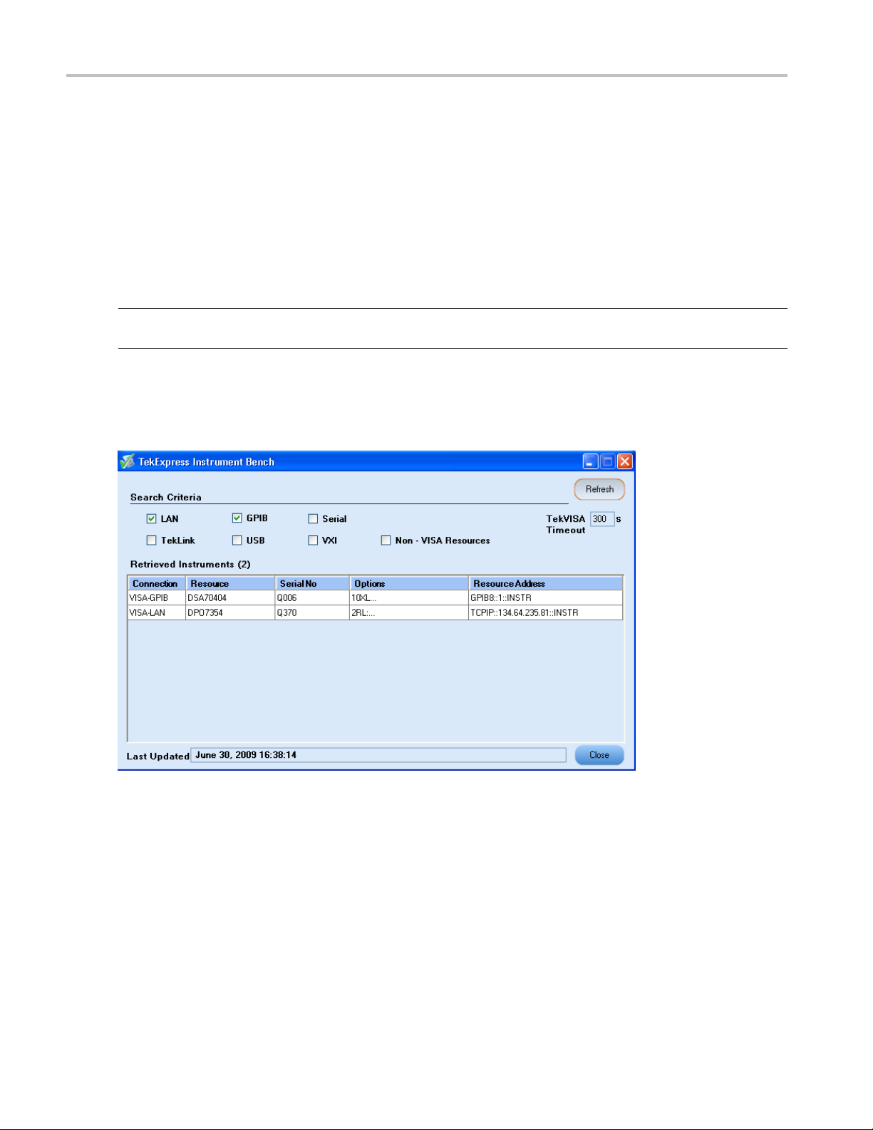
Instrument Bench
The Instrument Bench window shows the list of VISA and Non-VISA resources found on different
interfaces/connections. It serves two purposes at the launch of TekExpress:
Discovers the connected instruments.
Confirms the instrument connection setup.
When you click Tools > Instrument Bench, the following dialog box is displayed:
E-mail Settings
-mail Settings utility allows you to configure and set the e-mail options. The following fields are
The E
mandatory for receiving e-mail notification from TekExpress:
1. Rec
2. Sender's Address
3. SMTP Server address of the Mail server configured at client location
ipient Email Addres ses. For example, User@domain.com
16 TekExpress D-PHY Automated Solution
Page 29

Operating Basics Menus
If any of the above mentioned fields are left blank, the settings will not get saved and e-mail notification
will not be sent.
Check the option “ E-mail Test Results When Complete or on Error” to receive the e-mail. The attachment
list depends on the choice which is made while configuring the email setup.
NOTE. The Analysis Screenshot option in the Add Email Attachments pane is not yet functional.
Help Menu
Click Help on the application menu bar.
The Help menu has the following selections:
Menu Function
TekExpress Help
About TekExpress Displays the TekExpress s creen with the application title.
Activate License (see page 7) Displays the details of activating the application.
xxx
Displays TekExpress Help (F1).
Also displays the application details such as software name,
version number, and copyright.
TekExpress D-PHY Automated Solution 17
Page 30

Operating Basics Menus
18 TekExpress D-PHY Automated Solution
Page 31

How To Select Test(s)
Select Test(s)
The application supports the following D-PHY tests:
Group 1 tests that are Single-ended tests and available only in the Escape mode:
1.1.1 Data Lane LP-TX Thevenin Output High Level Voltage (VOH) (Single-ended only)
1.1.2 Data Lane LP-TX Thevenin Output Low Level
1.1.3DataLaneRiseTime(Single-endedonly)
1.1.4. Data Lane Fall Time (Single-ended only)
1.1.5. Data Lane LP-TX Slew Rate versus CLOAD (ōVō/tSR) (Single-ended only)
1.1.6. Data Lane LP-TX Pulse Width of Exclusive-OR Clock (TLP-PULSE-TX) (Single-ended only)
1.1.7. Data Lane LP-TX Period of Exclusive-OR Clock (TLP-PER-TX) (Single-ended only)
NOTE. Group 1 tests are supported on LP-HS waveforms although it is not recommended to use LP-HS
waveforms for these tests.
Group 2 tests that are Single-ended tests and available only in the Escape mode:
1.2.1 Clock Lane LP-TX Thevenin Output High Level Voltage (VOH) (Single-ended only)
1.2.2 Clock Lane LP-TX Thevenin Output Low Level Voltage (VOL) (Single-ended only)
1.2.3 C lock Lane Rise Time (S
1.2.4. Clock Lane Fall Time (Single-ended only)
1.2.5. Clock Lane LP-TX Slew Rate versus CLOAD (ōV/ōtSR) (Single-ended only)
ingle-ended only)
Voltage (VOL) (Single-ended only)
NOTE. Group 2 tests are supported on LP-HS waveforms although it is not recommended to use LP-HS
waveforms for these tests.
Group 3 tests:
The following Group 3 tests are single-ended and differential tests, except where indicated:
1.3.1 Data Lane HS Entry: Data Lane TLPX Value (Single-ended only)
NOTE. The Data Lane HS Entry: Data Lane TLPX Value test is supported on LP-HS waveforms although
it is not recommended to use LP-HS waveforms for this test.
1.3.2DataLaneHSEntry: THS-PREPAREValue
TekExpress D-PHY Automated Solution 19
Page 32

How To Select Test(s)
1.3.3DataLaneHSEntry: THS-PREPARE+THS-ZEROValue
1.3.4 Data
1.3.5 Data Lane HS-TX Differential Voltage Mismatch (ΔVOD)
1.3.6 Data Lane HS-TX Single-ended Output High Voltages (VOHHS(DP)), VOHHS(DN))
(Single-ended only)
1.3.7 Data Lane HS-TX Common Mode Voltages (VCMTX(1), VCMTX(0))
1.3.8 Data Lane HS-TX Common Mode Voltage Mismatch (ΔVCMTX(1,0))
1.3.9 Data Lane HS-TX Dynamic Common-Level Variations Between 50–450MHz (ΔVCMTX(HF))
1.3.10 Data Lane HS-TX Dynamic Common-Level Variations Above 450MHz (ΔVCMTX(HF))
1.3.11 Data Lane HS-TX 20%–80% Rise Time (tR)
1.3.12 Data Lane HS-TX 80%–20% Fall Time (tF)
1.3.13 Data Lane HS Exit: THS-TRAIL Value
1.3.14 Data Lane HS Exit 30%–80% POST-EoT Rise Time (TREOT)
1.3.15. Data Lane HS Exit: TEOT Value
1.3.16. DATA Lane HS Exit: THS-EXIT Value
Group 4 tests:
The following Group 4 tests are single-ended and differential tests, except where indicated:
Lane HS-TX Differential Voltages (VOD(0), VOD(1))
1.4.1 Clock Lane HS Entry: TLPX Value (Single-ended only)
1.4.2 Clock Lane HS Entry: TCLK-PREPARE Value (Single-ended only)
1.4.3 Clock Lane HS Entry: TCLK-PREPARE+ TZERO Value (Single-ended only)
1.4.4 Clock Lane HS-TX Differential Voltages (VOD(0), VOD(1))
1.4.5 Clock Lane HS-TX Differential Voltage Mismatch (ΔVOD)
1.4.6 Clock Lane HS-TX Single-ended Output High Voltages (VOHHS(DP)), VOHHS(DN))
(Single-ended only)
1.4.7 Clock Lane HS-TX Common Mode Voltages (VCMTX(1), VCMTX(0)) (Single-ended only)
1.4.8 Clock Lane HS-TX Common Mode Voltage Mismatch (ΔVCMTX(1,0)) (Single-ended only)
1.4.9 Clock Lane HS-TX Dynamic Common-Level Variations Between 50–450MHz (ΔVCMTX(LF))
(Single-ended only)
1.4.10 Clock Lane HS-TX Dynamic Common-Level Variations Above 450MHz (ΔVCMTX(HF))
(Single-ended only)
1.4.11 Clock Lane HS-TX 20%–80% Rise Time (tR)
1.4.12 Clock Lane HS-TX 80%–20% Fall Time (tF)
1.4.13 Clock Lane HS Exit: TCLK-TRAIL Value (Single-ended only)
20 TekExpress D-PHY Automated Solution
Page 33

How To Select Test(s)
1.4.14 Clock Lane HS Exit 30%–80% POST-EoT Rise Time (TREOT) (Single-ended only)
1.4.15. Clock Lane HS Exit: TEOT Value (Single-ended only)
1.4.16. Clock Lane HS Exit: THS-EXIT Value (Single-ended only)
1.4.17 Clock Lane HS Clock Instantaneous (UIINST) (Single-ended only)
Group 5 test
s:
The following Group 5 tests are single-ended and differential tests, except where indicated:
1.5.1 HS Entry: TCLK PRE Value
1.5.2 HS Entry: TCLK POST Value
1.5.3 HS Clock Rising Edge Alignment to First Payload Bit (Single-ended only)
1.5.4. Data-to-Clock Skew (TSKEW[TX])
NOTE. Group 5 tests are not available in the Clock Continuous mode.
The fol
Clock m
Normal Normal
Normal Escape
lowing table lists the tests (ids) that are supported in the clock and test modes:
ode
Test mo
de
s
Test id
e-ended tests: Group 3, Group 4, and Group 5.
Singl
Test ids: 1.3.1, 1.3.2, 1.3.3, 1.3.4, 1.3.5, 1.3.6, 1.3.7,
1.3.8, 1.3.9, 1.3.10, 1.3.11, 1.3.12, 1.3.13, 1.3.14, 1.3.15,
6.
1.3.1
Test ids: 1.4.1, 1.4.2, 1.4.3, 1.4.4, 1.4.5, 1.4.6, 1.4.7,
1.4.8, 1.4.9, 1.4.10, 1.4.11, 1.4.12, 1.4.13, 1.4.14, 1.4.15,
16, 1.4.17.
1.4.
Test ids: 1.5.1, 1.5.2, 1.5.3, 1.5.4.
Differential tests: Group 3, Group 4, and Group 5.
Test ids: 1.3.2, 1.3.3, 1.3.4, 1.3.5, 1.3.7, 1.3.8, 1.3.9,
.10, 1.3.11, 1.3.12, 1.3.13, 1.3.14, 1.3.15, 1.3.16.
1.3
Test ids: 1.4.4, 1.4.5, 1.4.11, 1.4.12, 1.4.17.
Test ids: 1.5.1, 1.5.2, 1.5.4.
Single-ended tests: Group 1, Group 2, and Group 3.
st ids: 1.1.1, 1.1.2, 1.1.3, 1.1.4, 1.1.5, 1.1.6, 1.1.7 Test
Te
ids: 1.2.1, 1.2.2, 1.2.3, 1.2.4, 1.2.5.
Test id: 1 .3.1
TekExpress D-PHY Automated Solution 21
Page 34

How To Select Test(s)
Clock mode Test mode Test ids
Continuous
xxx
Use the Sel
Normal
Single-ended
Test ids: 1.3.1, 1.3.2, 1.3.3, 1.3.4, 1.3.5, 1.3.6, 1.3.7,
1.3.8, 1.3.9, 1.3.10, 1.3.11, 1.3.12, 1.3.13, 1.3.14, 1.3.15,
1.3.16.
Test ids: 1.4.4, 1.4.5, 1.4.6, 1.4.7, 1.4.8, 1.4.9, 1.4.10,
1.4.11, 1.4.12, 1.4.17.
Differential tests: Group 3 and Group 4.
Test ids: 1.
1.3.10, 1.3.11, 1.3.12, 1.3.13, 1.3.14, 1.3.15, 1.3.16.
Test ids: 1.4.4, 1.4.5, 1.4.11, 1.4.12, 1.4.17.
ect panel to select configure, and run one or more groups of tests.
tests: Group 3 and Group 4.
3.2, 1.3.3, 1.3.4, 1.3.5, 1.3.7, 1.3.8, 1.3.9,
Select Device. Select the device type from the list: D-PHY CSI-2 or D-PHY DSI. The default value is
D-PHY-CSI-2. Enter the DUT ID for the device.
Select Clock Mode. Select the Clock Mode: Normal or Continuous. Select Continuous when the signal has
only the high speed region. Select Normal when the signal has both, the high speed and the low power
regions. The application uses Edge trigger for Continuous mode and Transition trigger for Normal mode.
The default Sample rate is 12.5 Gs/s and the default Record Length is 1M.
Select Clock Lane Probing. Select the probing method: D ifferential or Single-Ended. Based on this
selection, the application displays the single-ended and differential tes ts. If probing type is Single-ended
22 TekExpress D-PHY Automated Solution
Page 35

How To Configure and Run the Test(s)
then you will need four probes (Dp, Dn, Clkp, Clkn). If probing type is Differential, then you will need
three probes (Dp, Dn, Clkp-Clkn). Group 1 and Group 2 tests are not available for the Differential
probing metho
d
Select Lanes to Test. Select the lane to test. You can manually select the lanes to test, or you can select
Automate Lane Switching with RF switch. If you select multiple lanes without automation, a control
window is displayed when you need to switch the probing to the next lane. If you select automated lane
switching, the system automatically switches to the next lanes for you.
Select Test Mode. Select the test mode from the list: Normal or Escape. The default value is Normal.
Escape is available only when the Clock Mode is Normal. The application does not support Clock
continuous mode for Escape mode tests. As a result, the trigger is Transition trigger. When you select
Escape mode, you must connect a ULPS signal to the oscilloscope on which the measurements will be
done. However, the application can still perform the measurements on the LP-HS signals. The default
Sample r
ate is 12.5 Gs/s and the default Record Length is 1M.
Version. Select the Compliance Test Specification version, the default value is CTS 1.0. For the selected
CTS v ersion, select any particular test, or one or more test groups.
3: Select panel buttons
Table
n
Butto
xxx
Configure and Run the Test(s)
The configuration panel is used to view and edit the parameters associated with the acquisition and the
analysis of the selected test. Click here
Descr
Opens
Opens the schematic for the selected test. This is useful if
you w
Sele
Dese
for the options.
iption
the configuration panel for the selected test.
ant to verify the test setup before running the test.
cts all tests in the table.
lects all tests in the table.
TekExpress D-PHY Automated Solution 23
Page 36

How To Configure and Run the Test(s)
NOTE. If any of the test parameters are grayed, it means that these parameters are not editable.
The upper part of the Configuration Panel shows parameters and their values. These parameters are
common for a group of tests. Parameters specific to a select test are shown in the lower part of t he
Configuration Panel. Test-specific parameters include acquisition, analysis, and limit parameters.
ollowing table lists the common parameters and their values:
The f
Table 4: Common parameters and values
Parameter Value
Real Time Scope Select the oscilloscope to which to connect.
Measurement Method
Select the measurement method: Automatic or Manual. In the
Automatic mode, you perform a test without any intervention. In
the Manual mode, you will be prompted to place the cursors on the
acquired waveform before the application proceeds with the analysis.
NOTE. The Manual method is available only in the User Defined
mode.
24 TekExpress D-PHY Automated Solution
Page 37

How To Configure and Run the Test(s)
Table 4: Common parameters and values (cont.)
Parameter Value
Filter File 1 (for testing in Temperature Chamber) Select the filter file to use for temperature chamber testing. Click on
the browse button in the field and select a file.IfyouselectNone,no
filter file is used (testing in temperature chamber is not considered).
NOTE. Filter file selection is available only in the User Defined mode.
Filter File 2 (for testing in Temperature Chamber
with Differential Probing)
Select the filter file to use with differential probing for temperature
chamber testing. Click on the browse button in the field and select a
file. If you select None, no fi lter file is used (testing in temperature
chamber is not considered).
NOTE. Filter file selection is available only in the User Defined mode.
xxx
NOTE. If you change the channel selection for Data+ (DP), Data– (DN), Clock+ (CP), and Clock–
(CN) signals, make sure that you change the trigger source correspondingly in the Analyze tab for each
of the measurements. If you do not do this, the waveform might not trigger and the measurements might
not be completed.
For temperature chamber testing, a filter file with S4 parameters is used to compensate the factors
introduced due to length of the probe cable when testing the DUT in temperature chamber. You will need
one or two filter files based on the selected clock probing. If you select Single-ended probing, you must
specifyonlyonefilter file (Filter File 1). The application ignores the Filter File 2 even if you provide it. If
elect Differential probing, then you must specify both the filter files (Filter File 1 and Filter File 2).
you s
The following table lists the tabs and button controls for the tests:
Table 5: Configure panel buttons
Configure parameters Description
Acquire (see page 26) Shows the various parameters related to acquisition of a selected test.
Analyze (see page 28) Shows the various parameters r elated to analysis of a selected test.
These parameters can vary from one test to another test. For example,
Vertical scale, Vertical offset, Horizontal scale, and others.
Limits (see page 27) Applies to a specific version. It shows the measurement lower and
upper limits using different types of comparisons like EQ(==), NE(!=),
GT(>), LT(<), GE(>=), LE(<=), GTLT(> <), GELT(>= <), GTLE(> <=),
LTGT(< >), LEGE(<= >=), LEGT(<= >), LTGE(< G=), GELE(>= <=).
Some use unary operands and some use binary operands. For unary
operands, only value1 (on the left) is active.
Comments Specify a comment up to 256 characters long for selected test.
Restore
Save Saves and applies the configuration parameters that you have set.
Cancel
xxx
Restores the default values.
Dismisses the dialog box.
Click Run in the Select panel to run the selected tests.
TekExpress D-PHY Automated Solution 25
Page 38

How To Configure and Run the Test(s)
Refer to the following table for various test limit comparisons:
Table 6: Test limit comparisons
Comparison string Description
EQ(==)
NE(!=)
Equal to
Not equal to
GT(>) Greater than
LT(<)
Less than
GE(>=) Greater than or Equal to
LE(<=)
Less than or Equal to
GTLT(><) Greater than and Less than
GELT(>=<) Greater than or equal to and Less than
GTLE(><=) Greater than and Less or equal to
LTGT(<>) Less than and Greater than
LEGE(<= >=) Less than or equal to and Greater than or equal to
LEGT(<= >) Less than or equal to and Greater than
LTGE(< >=) Less than and Greater than or equal to
GELE(>= =<) Greater than or equal to and Less than or equal to
xxx
Configure Acquire Panel
26 TekExpress D-PHY Automated Solution
Page 39

How To Configure and Run the Test(s)
You have the following options:
Restore compliance mode values.
Change the parameters associated with analysis configuration.
Change the test limits in the U ser Defined mode.
Add comments
for the selected test that would appear in the Report panel.
ConfigureLimitsPanel
TekExpress D-PHY Automated Solution 27
Page 40

How To Typical Configuration Parameters
Configure Analyze Panel
Typical Configuration Parameters
The following table shows the typical or default configuration parameters for single-ended and differential
tests in the clock normal and clock continuous modes.
28 TekExpress D-PHY Automated Solution
Page 41

How To Typical Configuration Parameters
ests
Clock
lane
tests
Acquire
parameters
Vertical
Single-ended tests
(Clock Mode Normal)
Data
lane
tests
Clock
lane
tests
Single-ended
tests(ClockMode
Continuous)
Data
lane
tests
Clock
lane
tests
Differential tests
(Clock Mode Normal)
Data
lane
tests
Clock
lane
tests
Differential t
(Clock Mode
Continuous)
Data
lane
tests
200 200 200 200 200 200 200 200
Scale (mV)
Vertical Po
sition
–2.6 NA –2.6 NA –2.6 NA –2.6 NA
for Data (div)
Vertical Po
sition
NA –2.6 NA –2.6 NA 2.6 NA 2.6
for Clock (div)
Vertical
–2.6 –2.6 –2.6 –2.6 2.6 2.6 2.6 2.6
Position (div)
Vertical O ffset (V)
Horizontal Scale
00000000
88888888
(us)
Sample Rate
12.5 12.5 12.5 12.5 12.5 12.5 12.5 12.5
(GS/s)
Record Length 1000000 1000000 1000000 1000000 1000000 1000000 1000000 1000000
Analyze parameters
Trigge
rType
Transi
tion
Transi
tion
-
Transi
-
tion
Transi
tion
-
Edge Transi
-
tion
Transi
tion
-
Edge
Trigger Source Ch1 Ch3 Ch1 Ch3 Ch1 C h3 Ch1 Ch3
ger Upper
Trig
111NA111NA
Level (V)
ger Lower
Trig
0.05 0.05 0.05 0.05 0.05 0.05 0.05 0.05
Level (V)
Trigger Level for
NA NA NA 0.2 NA NA 0.2 0.2
Continuous Clock
e(V)
Mod
igger Time (ps)
Tr
Trigger Transition
Trigger Slope
Trigger If Violation Occurs Occurs Occurs
xxx
500 500 500 500 500 500 500 500
eater
Gr
Than
ositive,
P
Negative
eater
Gr
Than
ositive,
P
Negative
eater
Gr
Than
ositive,
P
Negative
NA
ositive,
P
Negative
A
N
eater
Gr
Than
ositive,
P
Negative
eater
Gr
Than
ositive,
P
Negative
eater
Gr
Than
ositive,
P
Negative
Occurs Occurs Occurs
NA
ositive,
P
Negative
A
N
TekExpress D-PHY Automated Solution 29
Page 42
How To View and Select Connected Instruments
View and Select Connected Instruments
Viewing Conne
The Tools > Instrume nt Bench menu item is used to discover connected instruments required for the
tests. The ap
the Instrument Bench dialog box resumes operation and lists the instrument-related details based on the
selected search criteria.
NOTE. When the TekVISA Instrument Manager checks for connected Instruments, the Instrument Bench
dialog box does not respond.
For example, if you select LAN and GPIB as the search criteria in the Instrument Bench dialog box and
click Refresh, the TekVISA Instrument Manager checks for the availability of instruments over LAN and
the details of the instruments are displayed under Retrieved Instruments table.
cted Instruments
plication uses TekVISA to discover the connected instruments. Once the operation is done,
ovide the time in the TekVISA Refresh Timeout (Seconds) field, within which if the TekVISA
Pr
Instrument Manager does not find the instruments, the TekExpress application resumes the operation. If
you choose Non-VISA resources, all the instruments supported by TekExpress but not communicating
over the VISA layer can be searched.
30 TekExpress D-PHY Automated Solution
Page 43

How To Acquire Live Waveform for Analysis
Selecting Connected Instruments
View the instruments connected in the Configuration panel. The upper half of the panel displays the
general param
from the drop-down list.
eters for the tests under the selected test suite. Select the Real Time Scope to connect to
NOTE. The list of instruments displayed is specific to the selected test suite. It does not show all the
connected instruments.
Acquire Live Waveform for Analysis
Select the Acquire tab to view the acquisition parameters. Select the Data (Dp and Dn) and Clock (Clkp
Clkn) sources. When you click Run, by default the application acquires live signals from the source.
and
Click the Acquire tab to see acquisition parameters, and acquisition status of the selected test suite. The
quire panel is specific to a suite and gets updated every time the selected test suite is changed. This
Ac
panel shows the acquisition details for the tests in the currently selected suite. The tests with common
acquisition parameters are grouped together and shown as a single acquisition.
TekExpress D-PHY Automated Solution 31
Page 44

How To Acquire Live Waveform for Analysis
This example shows the acquire panel with channel selections.
32 TekExpress D-PHY Automated Solution
Page 45

How To Use Prerecorded Waveforms for Analysis
Table 7: Controls on the Acquire panel
Selection Function
Data Source Lists the sources assigned for each data line (Dp and Dn).
Select the source (channel) for each data line (Dp and Dn).
Once you select a channel for Dp, you cannot select the
same channel for other lines (Dn, Clkp, and Clkn) and vice
versa).
Clock Source Lists the sources assigned for each clock line (Clkp and
Clkn). Select the source (channel) for each clock line (Dp
and Dn). Once you select a channel for Clkp, you cannot
select the same channel for other lines (Dn, Dn, and Clkn)
and vice versa).
If you have selected Differential Clock Lane Probing in
the Select panel, only one source selection is displayed
(differential probe clock needs only one channel as source).
Column Name
Test
Status Acquisition status of the running test at intervals. The
Acquisition
Acquire Option s
Use Pre-recorded Waveform Files When enabled, uses pre-recorded waveforms for the
Acquire Step By Step When enabled, displays the reference input waveform of
xxx
Displays the name of the selected test for performing
acquisitions. One or more tests can perform the same
acquisitions.
messages are passed only in live acquisition.
Updates the location of the acquisition name.
selected test.
the selected test. This helps you to compare the input
waveform with the reference waveform, allows you to
change the setup before acquiring the waveforms, and then
proceeds with the next selected test.
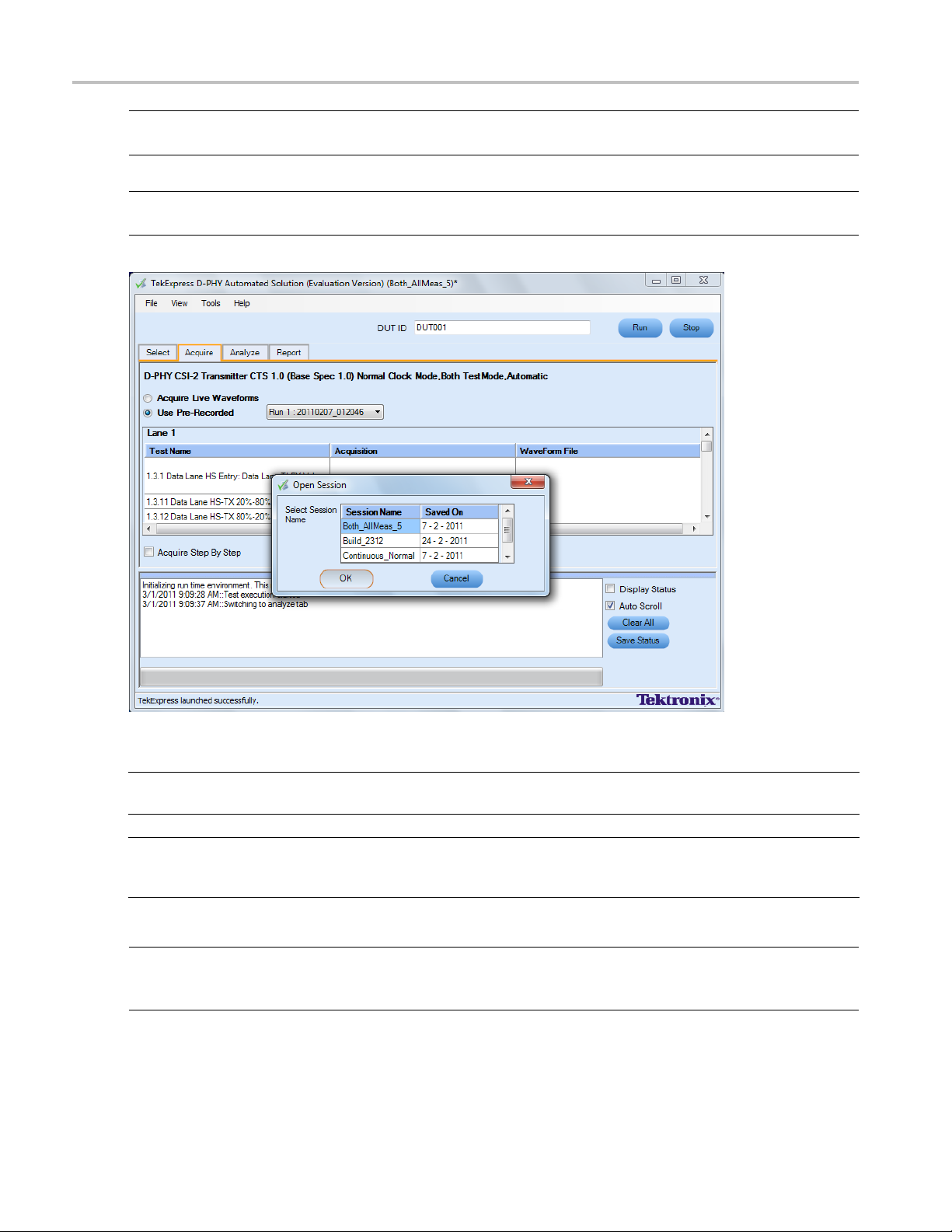
Use Prerecorded Waveforms for Analysis
Select the Acquire tab to see unique acquisitions, acquisition parameters, acquisition status, and
prerecorded waveform files of the selected test suite. The Acquire panel is specific to a group and gets
updated every time the selected test group is changed. This panel shows the acquisition details for the
tests in the currently selected g roup. The tests with the common acquisition parameters are grouped
together and shown as a single acquisition.
For pre-recorded testing, it is recommended that you capture the waveforms at 12.5 Gs/s sample rate.
However, if you capture the waveforms at a different sample rate, ensure that you change the Sample Rate
parameter in the Configure Panel appropriately for each of the selected tests.
TekExpress D-PHY Automated Solution 33
Page 46
How To Use Prerecorded Waveforms for Analysis
NOTE. You can only use saved sessions in which the tests have been run in Automatic mode for prerecorded
testing. You cannot use the sessions in which tests have been run in Manual mode for prerecorded testing.
NOTE. You cannot use the prerecorded waveform option for the 1.5.3 HS Clock Rising Edge Alignment to
First Payload Bit test.
Column name Function
Test N ame
Acquisition
Waveform File Prerecorded waveform files of unique acquisitions. You can select waveform
xxx
Name of the tests performing acquisitions. One or more tests can perform
the same acquisitions.
Test acquisition status of the running test passed at intervals.
files by clicking the hyperlink. This allows you to select any waveform file using
the standard file open window.
NOTE. To use the prerecorded option, it is recommended that you use a waveform file (.wfm) which has
been captured from a Tektronix oscilloscope. This eliminates the need to use an oscilloscope. You can
manually select waveforms and perform the tests with a click of the Run button.
34 TekExpress D-PHY Automated Solution
Page 47

How To View the Progress of Analysis
The following Acquire source options are available:
Use Pre-recorded Waveform Files: Enabling or disabling the option shows or hides the waveform
file column in the acquisition table.
Follow these steps to save a session and use the pre-recorded mode to run it:
a. Open a new session.
b. Select the tests.
c. Highlight a
each of the selected tests.
d. Save the se
e. In the Acquire panel, select Use Pre-recorded Waveform Files and then select the waveforms for
each of th
the data and clock waveforms. For example.....
Acquire
to the next one.
Show Ac
When you select “Use Pre-recorded”, the first column shows the Acquisition, the second column shows
st, and the next column shows the Waveform File for analysis.
the Te
test and click Configure. Change the sample rate parameter to the desired value for
ssion.
e tests. Make sure that the waveform names have a suffix DP, DN, CP, and CN indicating
Step by Step: Selecting this prompts you at the end of each acquisition before proceeding
quire Parameters: Selecting this shows the acquisition parameters.
ViewtheProgressofAnalysis
Click the Analyze tab to view the progress of the analysis. As the analysis of each test is complete, the
ult value is updated.
res
TekExpress D-PHY Automated Solution 35
Page 48

How To View the Progress of Analysis
Analyz
The Analyze table contains the following:
The tests that are not yet started are shown with a “To be Started” status. A summarized status of the
currently running test is shown in the Status Messages panel.
The Status Messages window time-stamps all ru
following:
eTable
The test name.
The status of the tests that are being run.
The low and high limit values, and margins, for the tests.
The measured values for the tests.
The pass/fail status of the tests.
n time messages and displays them. You can do the
Display Status: Enable/Disable status messages.
Auto Scroll: Scroll the status messages automatically.
Clear All: Clear all status messages in Status Window.
Save Status: Save all status messages in text file. Displays a standard save file window a nd saves the
status messages in the user specified file.
36 TekExpress D-PHY Automated Solution
Page 49
How To View the Report
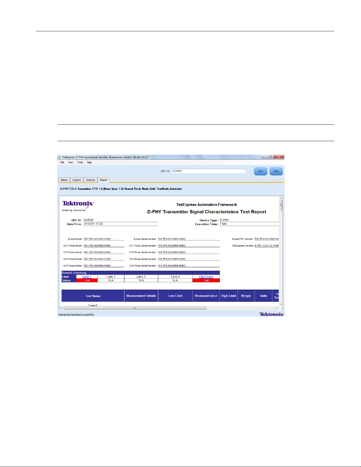
View the Report
After the analysis, a report is automatically generated and displayed in the report panel. The device
information such as oscilloscope model, serial number, firmware version of the oscilloscope, version
information
A t able shows the test name, measurement details, test result (pass/fail), compliance mode, and analysis
time. Save t
NOTE. If you use a secondary m onitor, verify that the screen resolution of the secondary monitor is the
same as that of the primary display. This ensures that captured images in the reports are of the same size.
of the TekExpress and the application, start time, and the execution time are displayed.
he report as an MHT file using the File > Save As option.
TekExpress D-PHY Automated Solution 37
Page 50

How To View Test Related Files
View Test Related Files
All the test related files for currently selected tests are always saved under: My Documents\My
TekExpress\D-PHY\SessionName
.
Case 1. An example image of data when the session is still not saved and is in the
path as “Untitled Session”,theDUTIDissettoDUT001, and the tests are performed twice (two
folders are created with the file naming convention
Case 2. An example image of data when the session is still not saved and is in the My TekExpress/D-PHY
path as “Untitl ed Session”,theDUT001 folder already present (tests are performed twice), and the
DUT ID is now set to
DUT002 (here the tests are performed once).
YYYYMMDD_HHMMSS (Date_Time).
My TekExpress/D–PHY
Case 3. An example image of data when the session is saved and is in the My TekExpress/D-PHY
has
pat
38 TekExpress D-PHY Automated Solution
“Test”.
Page 51

Application Examples View Test Related Files
TekExpress D-PHY Automated Solution 39
Page 52

Application Examples Connection Setup
Connection Setup
Youneedthefollowingequipment(seeCompatibility (see page 3)):
A supported Tektronix DPO oscilloscope
Single-ende
Differential probe
Device under test
Probing board
NOTE. If you have a partial setup, such as only Tx and no Rx, then the probing board should be connected
to the termination board, which provides proper termination for the LP and HS signals. If you have a full
setup, t
Make co
hen there is no need for the termination board.
For multilane testing, RF switch:
nnections as follows for single-ended tests:
dprobe
40 TekExpress D-PHY Automated Solution
Page 53
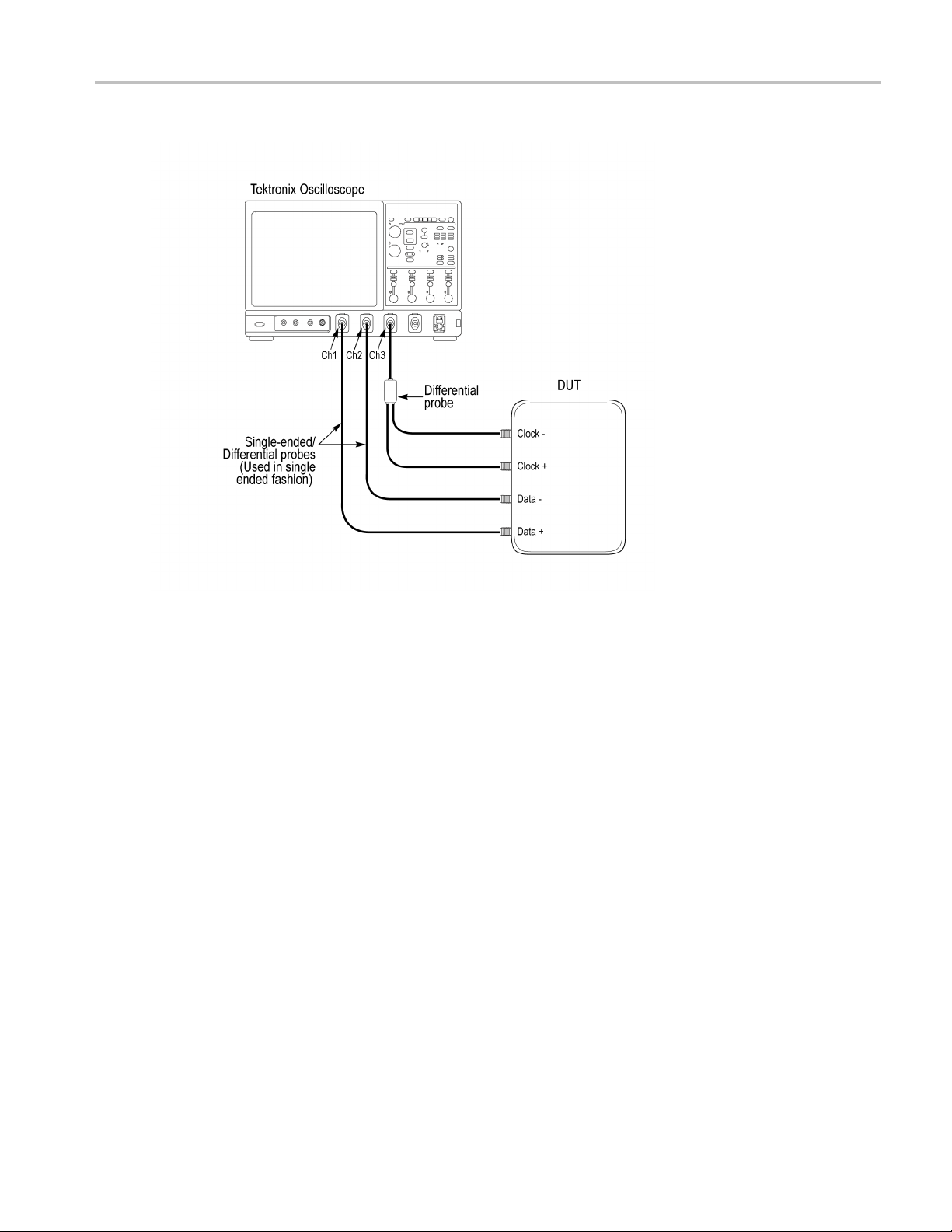
Application Examples Connection Setup
Make connections as follows for differential tests:
TekExpress D-PHY Automated Solution 41
Page 54
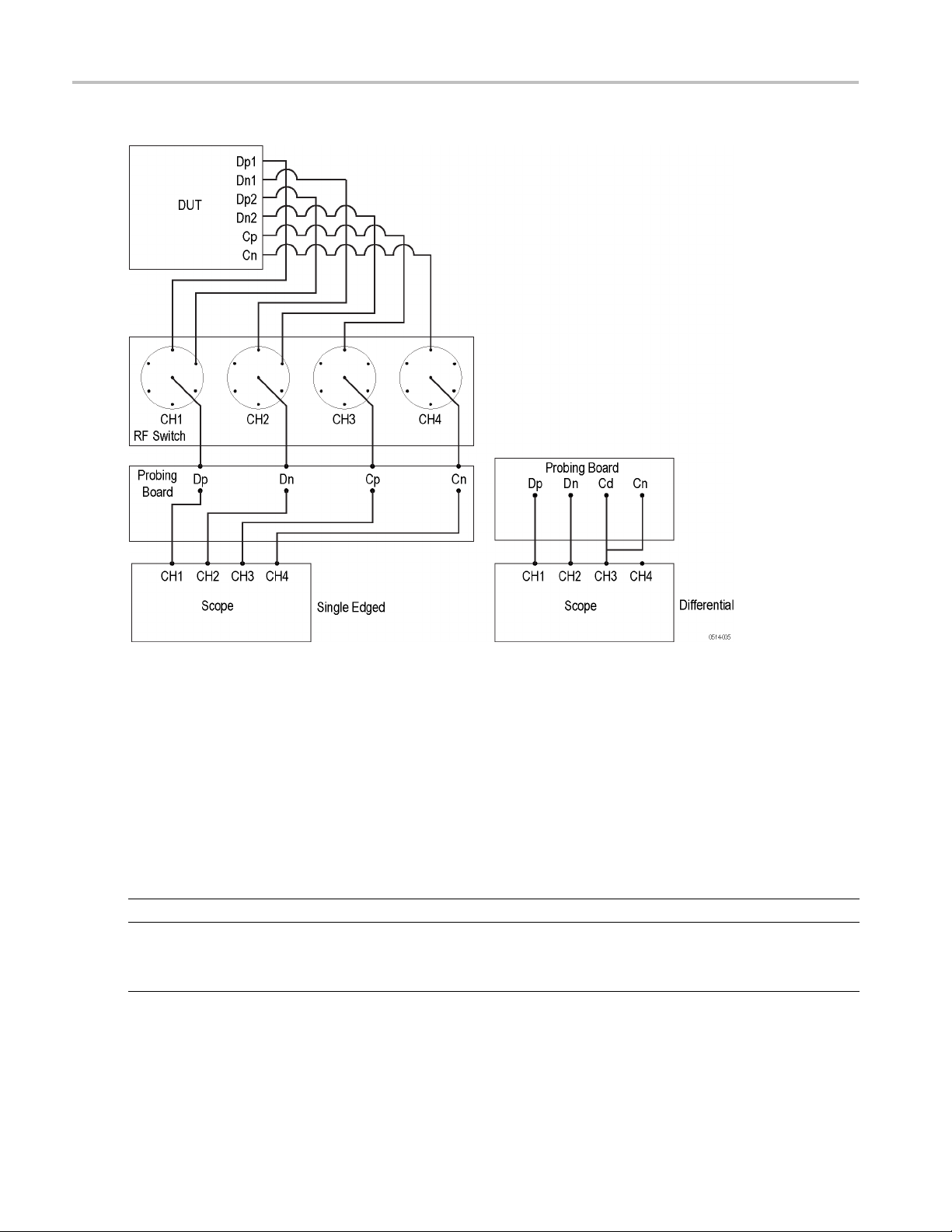
Application Examples Configuring Parameter Values
Make connections as follows when you are using an RF switch and probing board:
Config
42 TekExpress D-PHY Automated Solution
uring Parameter Values
To con
1. In the Select panel click Configure.
2. In the Configure panel, set the following general parameters that are common for all tests:
Parameter Value
Real Time Scope Select the oscilloscope to which to connect.
Mea
figure a test, do the following:
surement Method
Select the measurement method: Automatic or Manual.
NOTE. The Manual method is available only when in the User
fined mode.
De
Page 55

Application Examples Temperature Chamber Testing
Filter File 1 (f
Filter File 2 (
with Differential Probing)
or testing in temperature chamber)
for testing in temperature chamber
Select the filte
the browse button in the field and select a file.IfyouselectNone,no
filter file is used (testing in temperature chamber is not considered).
NOTE. Filter fi
Select the filt
chamber testing. Click on the browse button in the field and select a
file. If you select None, no fi lter file is used (testing in temperature
chamber is no
r file to use for temperature chamber testing. Click on
le selection is available only in the User Defined mode.
er file to use with differential probing for temperature
t considered).
NOTE. Filter file selection is available only in the User Defined mode.
xxx
The A utomatic measurement method mode, lets you perform a test without any intervention. You
must select one or more tests, configure the tests (or use the default values) and click Run to perform
the test. T
he application acquires and analyzes the data, and displays a report when complete.
If you select the Manual mode, select one or more tests, configure the tests (or use the default values)
and click
Run to perform the test. The application begins to acquire data. A window opens where
you are prompted to place the cursors on the acquired waveform a nd click OK. Go to the TekScope
application and zoom the waveform around the trigger point. Place the cursors on the waveform to
capture the values at those points and click OK in the window. The application completes the test
and displays the report.
For temperature chamber testing, a filter file with S4 parameters is used to compensate the factors
introduced due to length of the probe cable when testing the DUT in temperature chamber. You will
need one or two filter files based on the selected clock probing. If you select Single-ended probing,
you mu
st specify only one filter file (Filter File 1). The application ignores the Filter File 2 even if
you provide it. If you select Differential probing, then you must specify both the filter files (Filter
File 1 and Filter File 2).
NOTE. Other applications will display there windows in the background. The TekScope application takes
precedence over other applications. Use Alt+Tab to view the other application windows.
3. Select either Compliance M ode or User Defined Mode. In the User Defined Mode, you can modify
the test parameters but you will no longer be testing against the compliance standards.
Temperature Chamber Testing
The TekExpress D-PHY offers the temperature chamber testing which is done at system level when the
device is put in the oven and the connection points from the DUT are extended to the probe using a wire.
This wire is 60” (5 ft) long and the signal must be de-embedded for t he measurement. Filter files are
needed to offset the cable effects that are introduced in temperature chamber testing.
The setup shown below is expected to be done by the user. The DUT is ideally placed in an environment in
which t he temperature can be externally controlled, which we call the Temperature Oven. The DUT is
then connected to the setup using the above-mentioned long cables that come from within the oven to
TekExpress D-PHY Automated Solution 43
Page 56

Application Examples Temperature Chamber Testing
the Tektronix P7500 series probes that are then connected to the desired channels of the Tektronix real
time scope.
However, the P7500 probe does not support LP measurement but can support all measurements in normal
mode. All the measurements that can be performed using the LP-HS transition mode are supported in
Temper ature
The next specifies how to control this testing through the application once the setup is ready.
chamber mode.
Steps for Performing Temperature Chamber Testing
The a pplication provides a set of filter files. However, you have the option of selecting your own set of
filter files.
Temperature chamber testing is available only in the User Defined mode.
1. Select the test and click Configure.
2. Select the User Defined mode.
44 TekExpress D-PHY Automated Solution
Page 57

Application Examples Temperature Chamber Testing
3. Select Filter File1 by browsing to the folder.
4. Select Filter File 2 to use with differential probing for temperature chamber testing by browsing to
the folder.
Youwillneedoneortwofilter files based on the selected clock probing. If you select Single-ended
probing, you must specify only one filter file (Filter File 1). If you select Differential probing, then you
must specify both the filter files (Filter File 1 and Filter File 2).
The filter file for each of the combinations is listed in the table
Table 8: Filter file names
Selection Affected channels/Lanes File name
NORMAL CLOCK, SINGLE ENDED Dp, Dn,Cp,Cn Single ended filter for all lanes
NORMAL CLOCK, DIFFERENTIAL Dp, Dn,Cp-n Single ended for Data lane, Differential
filter for clock lane
CONTINUOUS CLOCK, SINGLE
ENDED
CONTINUOUS CLOCK,
DIFFERENTIAL
xxx
Dp, Dn,Cp, Cn Single ended filter for all lanes
Dp, Dn,Cp-n Single ended for Data lane, Differential
filter for clock lane
TekExpress D-PHY Automated Solution 45
Page 58
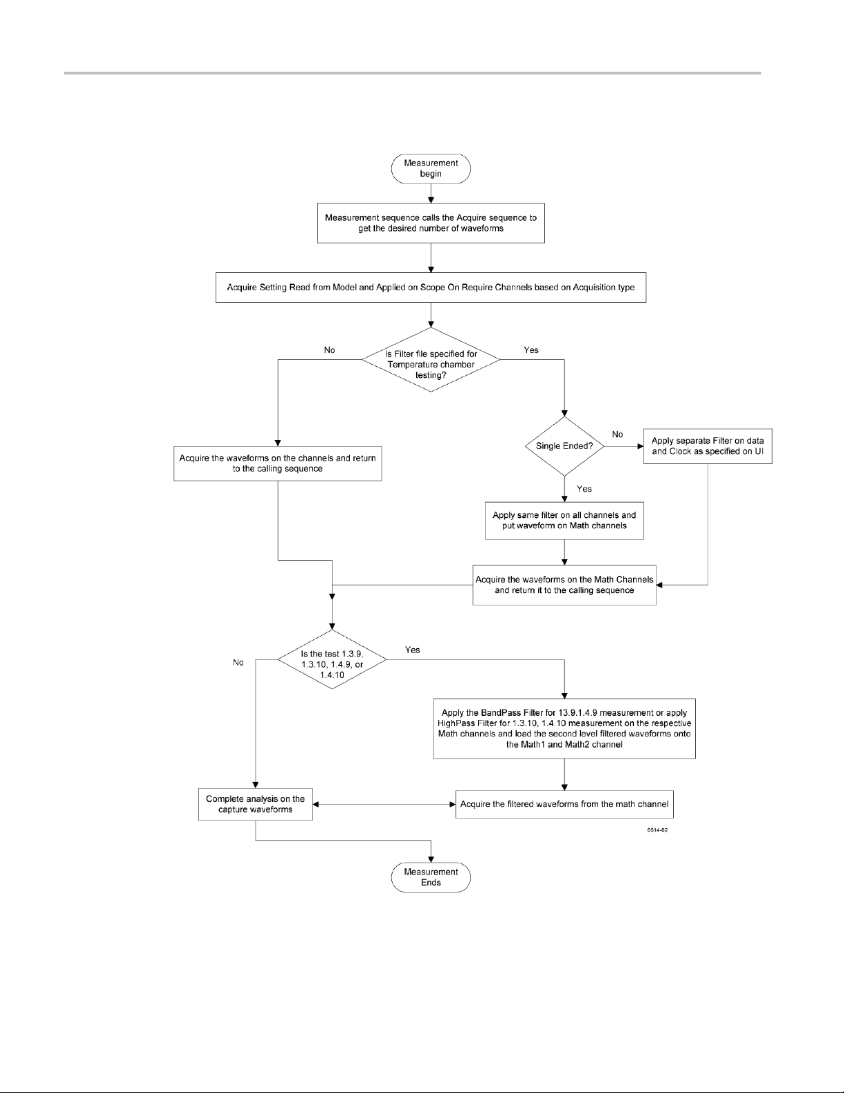
Application Examples Temperature Chamber Testing
Logic Flow of Temperature Chamber Testing in TekExpress D-PHY
46 TekExpress D-PHY Automated Solution
Page 59

Application Examples Multilane Testing with RF Switch
Multilane Testing with RF Switch
Multilane testing with an RF switch takes measurements on four lanes. The system can automatically
receive signals from all four lanes without user intervention, save the acquisitions, and then take
measurement
measurements are performed.
s on one lane, and then the signals from next lane are automatically selected and the
Without aut
omation you can select which lane (s) to test, and based on the selection, the application
acquires the desired signals and takes the selected measurements on those acquired waveforms. When
done with a lane, the software prompts you to change the connection over to the next lane.
After each acquisition the waveforms are saved, with proper naming convention for specific lanes,
analyzed, and the results for eac h lane updated in the analyze panel and the report panel.
Table 9: Required Equipment
Item Description
RF switch
Reference Termination Board
(otpional)
GPIB cable A GPIB cable is required when using an RF switch for multi-lane automation.
xxx
Keithley S46 series Microwave Switch System
D-PHY Reference Termination Board (RTB) available from University
of New Hampshire (UNH-IOL). This UNH RTB is orderable from,
http://www.iol.unh.edu/services/testing/mipi/MIPI_Test_Fixture_Order_Form.doc
Setting up Multilane Testing
Click here for information on connections for multilane testing. Perform the following steps to set up the
equipment for multilane testing:
1. Connect a GPIB cable between the oscilloscope and the RF switch.
2. Connect the input channels of the oscilloscope to the outputs of the Probing board.
3. Connect the inputs of the Probing board to the outputs of the RF switch.
4. Connect the Dp signals form each lane of the DUT to the inputs of channel 1 of the RF switch.
5. Connect the Dn signals from each lane of the DUT to the corresponding inputs of channel 2 of the
RF switch.
6. Connect the Cp signal to the input of channel 3 of the RF switch. The clock lane is connected through
the RF switch to ensure that there is no skew between the data and clock signals.
7. Connect the Cn signal to the input of channel 4 of the RF switch.
8. In the Select tab, select t he Automate Lane switching with RF switch check box
9. In the Acquire tab, select Acquire Live Waveforms.
10. Select RF Switch setup.
11. Map the lanes and input types to the location on the RF switch.
TekExpress D-PHY Automated Solution 47
Page 60
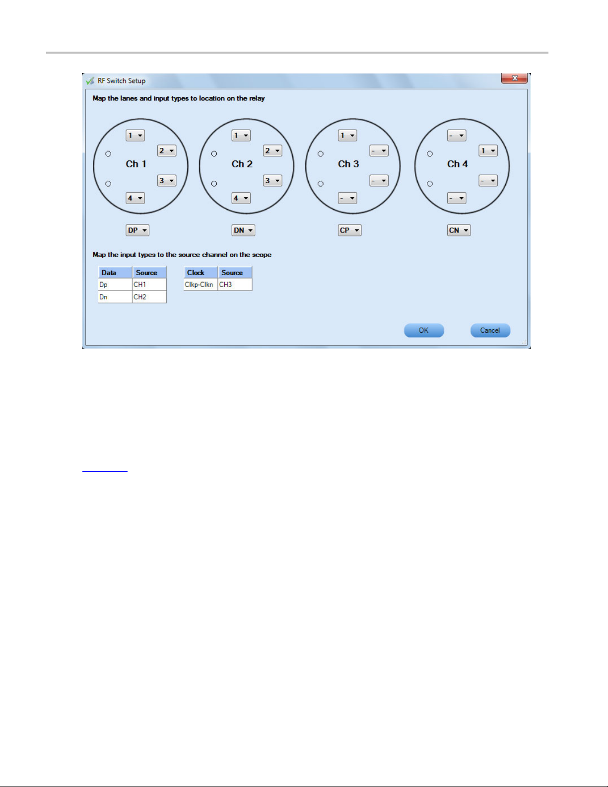
Application Examples Connections for Data Lane LP-TX Thevenin Output High Level Voltage (VOH)
Connect
(VOH)
Click h
(VOH) test.
Config
Volt
ure and Run Data Lane LP-TX Thevenin Output High Level
age (VOH)
1. In th
ions for Data Lane LP-TX Thevenin Output High Level Voltage
ere
for information on connections for the Data Lane LP-TX Thevenin Output High Level Voltage
e Select panel, select the Device.
48 TekExpress D-PHY Automated Solution
Page 61

Application Examples Configure and Run Data Lane LP-TX Thevenin Output High Level Voltage (VOH)
NOTE. The Data Lane LP-TX Thevenin Output High Level Voltage (VOH) test is not available when the
selected clock lane probing is Differential.
You can also perform Data Lane LP related measurements on a signal that has an LP-HS transition.
2. Select the Clock Mode as Normal.
3. Select Clock Lane Probing as Single-ended.
4. Select the Test Mode as Escape.
The Versio
n default value is CTS 1.0.
5. Select the test and click Configure.
6. In the Configuration Panel, set the following parameters for the acquire type (Data Lanes Acquisition
in Escape Mode with Data as Trigger). The following table lists the compliance mode values and the
permitt
ed range of values for the user-defined mode:
Table 10: Configuration parameters for Data Lane LP-TX Thevenin Output High Level Voltage (VOH)
Parameter Default User defined mode
Vertical Scale (mV)
Vertical P o sition for D ata (div)
Vertical Offset (V)
Horizontal Scale (us)
Sample Rate (GS/s)
Record Length 1000000 100000 to 10000000
xxx
7. Click Analyze. View and change the fol
200 100, 200, 300
–2.6 +3 to –3
0 Do not change
8 8, 10, 12
12.5 7.5, 10, 12.5
lowing analysis parameters:
Table 11: Analysis parameters for Data Lane LP-TX Thevenin Output High Level Voltage (VOH)
Parameter Default User defined mode
Trigger Type Transition Transition
Trigger Source Ch1 Ch1, Ch2, Ch3, Ch4
Trigger Upper Level (V)
Trigger Lower Level (V)
Trigger Time (pS)
Trigger Transition
Trigger Slope
Trigger If Violation Occurs Occurs, Logic
xxx
8. Click Limits to view and change the Data Lane LP-TX Thevenin Ou
1 Enter a value based on the test
0.05 0.05, 0.1, 1
500 250, 500
Greater Than Greater Than, Less Than
Positive Positive, Negative, Either
tput High Voltage DP and Data
Lane LP-TX Thevenin Output High Voltage DN values, and the compare string.
9. Click Comments to enter comments. The comments are shown in th
etestreport.
TekExpress D-PHY Automated Solution 49
Page 62

Application Examples Connections for Data Lane LP-TX Thevenin Output Low Level Voltage (VOL)
10. Click Save to accept the changes, o r click Cancel.
11. Click the Acquire tab to view the acquisition parameters. Select the Data (Dp and Dn) and Clock
(Clkp and Clkn) sources.
12. Click Run to start the test. The Acquire panel shows the progress and status of the test as it runs.
Connection
s for Data Lane LP-TX Thevenin Output Low Level Voltage
(VOL)
Click here f
(VOL) test.
or information on connections for the Data Lane LP-TX Thevenin Output Low Level Voltage
Configure and Run Data Lane LP-TX Thevenin Output Low Level Voltage
(VOL)
1. In the Select panel, select the Device.
NOTE. The Data Lane LP-TX Thevenin Output Low Level Voltage (VOL) test is not available when the
selected clock lane probing is Differential.
2. Select the Clock Mode as Normal.
3. Select Clock Lane Probing as Single-ended.
4. Select the Test Mode as Escape.
The Version default value is CTS 1.0.
5. Select the test and click Configure.
6. In the Configuration Panel, set the following parameters for the acquire type Data Lanes Acquisition
in Escape Mode with Data as Trigger. The following table lists the compliance mode values and the
permitted range of values for the user-defined mode:
Table 12: C onfiguration parameters for Data Lane LP-TX Thevenin Output Low Level Voltage (VOL)
Parameter Default User defined mode
Vertical Scale (mV)
Vertical Position for Data (div)
Vertical Offset (V)
Horizontal Scale (us)
50 TekExpress D-PHY Automated Solution
200 100, 200, 300
–2.6 +3 to –3
0 Do not change
8 8, 10, 12
Page 63

Application Examples ConnectionsforDataLaneRiseTime
Table 12: Configuration parameters for Data Lane LP-TX Thevenin Output Low Level Voltage (VOL) (cont.)
Parameter Default User defined mode
Sample Rate (GS/s)
Record Length 1000000 100000 to 10000000
xxx
12.5 7.5, 10, 12.5
7. Click Analyze. View and change the following analysis parameters:
Table 13:
Parameter Default User defined mode
Trigger T
Trigger
Trigge
Trigge
Trigg
Trigger Transition
Trig
gger If Violation
Tri
xxx
Analysis parameters for Data Lane LP-TX Thevenin Output Low Level Voltage (VOL)
ype
Source
r Upper Level (V)
r Lower Level (V)
er Time (pS)
ger Slope
on
Transiti
Ch1 Ch1, Ch2
1 Enter a value based on the test
0.05 0.05, 0.1, 1
500 250, 500
er Than
Great
Negative Positive, Negative, Either
urs
Occ
on
Transiti
, Ch3, Ch4
er Than, Less Than
Great
urs, Logic
Occ
8. Click Limits to view and change the Data Lane LP-TX Thevenin Output Low Voltage DP and Data
Lane LP-TX Thevenin Output Low Voltage DN values in mV, and the compare string.
9. Click Comments to enter comments. The comments are shown in the test report.
10. Click Save to effect the changes, or click Cancel.
lick the Acquire tab to view the acquisition parameters. Select the Data (Dp and Dn) and Clock
11.C
(Clkp and Clkn) sources.
12. Click Run to start the test. The Acquire panel shows the progress and status of the test as it runs.
Connections for Data Lane Rise Time
Click here for information on connections for the Data Lane Rise Time test.
ConfigureandRunDataLaneRiseTime
1. In the Select panel, select the Device.
TekExpress D-PHY Automated Solution 51
Page 64

Application Examples ConfigureandRunDataLaneRiseTime
NOTE. The Data Lane Rise Time test is not available when the selected clock lane probing is Differential.
2. Select the Clock Mode as Normal.
3. Select Clock Lane Probing as Single-ended.
4. Select the Test Mode as Escape.
The Version
default value is CTS 1.0.
5. Select the test and click Configure.
6. In the Configuration Panel, set the following parameters for the acquire type Data Lanes Acquisition
in Escape Mode with Data as Trigger. The following table lists the compliance mode values and the
permitte
d range of values for the user-defined mode:
Table 14: Configuration parameters for Data Lane Rise Time
Parameter Default User defined mode
Vertical Scale (mV)
Vertical Position (div)
Vertical Offset (V)
Horizontal Scale (us)
Sample Rate (GS/s)
Record Length 1000000 100000 to 10000000
xxx
200 100, 200, 300
–2.6 +3 to –3
0 Do not change
8 8, 10, 12
12.5 7.5, 10, 12.5
7. Click Analyze. View and change the following analysis parameters:
Table15: AnalysisparametersforDataLaneRiseTime
Parameter Default User defined mode
Trigger Type Transition Transition
Trigger Source Ch1 Ch1, Ch2, Ch3, Ch4
Trigger Upper Level (V)
Trigger Lower Level (V)
Trigger Time (pS)
Trigger Transition
Trigger Slope
Trigger If Violation Occurs Occurs, Logic
xxx
1 Enter a value based on the test
0.05 0.05, 0.1, 1
500 250, 500
Greater Than Greater Than, Less Than
Positive Positive, Negative, Either
8. Click Limits to view and change the Data Lane Rise Time DP and Data Lane Rise Time DN values in
nS, and the compare string.
9. Click Comments to enter comments. The comments are shown in the test report.
10. Click Save to effect the changes, or clickCancel.
52 TekExpress D-PHY Automated Solution
Page 65

Application Examples Connections for Data Lane Fall Time
11. Click the Acquire tab to view the acquisition parameters. Select the Data (Dp and Dn) and Clock
(Clkp and Clkn) sources.
12. Click Run to start the test. The Acquire panel shows the progress and status of the test as it runs.
Connections for Data Lane Fall Time
Click here for information on connections for the Data Lane Fall Time test.
ConfigureandRunDataLaneFallTime
1. In the Select panel, select the Device.
NOTE. The Data Lane Fall Time test is not available when the selected clock lane probing is Differential.
2. Select the Clock Mode as Normal.
3. Select
Clock Lane Probing as Single-ended.
4. Select the Test Mode as Escape.
The Version default value is CTS 1.0.
5. Select the test and click Configure.
6. In the Configuration Panel, set the following parameters for the acquire type Data Lanes Acquisition
in Escape Mode with Data as Trigger. The following table lists the compliance mode values and the
permitted range of values for the user-defined mode:
Table 16: Configuration parameters for Data Lane Fall Time
Parameter Default User defined mode
Vertical Scale (mV)
Vertical Position (div)
Vertical Offset (V)
Horizontal Scale (us)
Sample Rate (GS/s)
Record Length 1000000 100000 to 10000000
xxx
200 100, 200, 300
–2.6 +3 to –3
0 Do not change
8 8, 10, 12
12.5 7.5, 10, 12.5
7. Click Analyze. View and change the following analysis parameters:
TekExpress D-PHY Automated Solution 53
Page 66

Application Examples Connections for Data Lane LP-TX Slew Rate Versus CLOAD (ōVō/tSR)
Table 17: Analysis parameters for Data Lane Fall Time
Parameter Default User defined mod
Trigger Type Transition Transition
Trigger Source Ch1 Ch1, Ch2, Ch3, Ch4
Trigger Upper Level (V)
Trigger Lower Level (V)
Trigger Time (pS)
Trigger Transition
Trigger Slope
Trigger If Violation Occurs Occurs, Logic
xxx
8. Click Li
mits to view and change the Data Lane Fall Time DP and Data Lane Fall Time DN values in
1 Enter a value based on the test
0.05 0.05, 0.1, 1
500 250, 500
Greater Than Greater Than, Less Than
Negative Positive, Negative, Either
e
nS, and the compare string.
9. Click C
omments to enter comments. The comments are shown in the test report.
10. Click Save to effect the changes, or clickCancel.
11. Click the Acquire tab to view the acquisition parameters. Select the Data (Dp and Dn) and Clock
(Clkp and Clkn) sources.
12. Click Run to start the test. The Acquire panel shows the progress and status of the test as it runs.
Connections for Data Lane LP-TX Slew Rate Versus CLOAD (ōVō/tSR)
Click here for information on connections for the Data Lane LP-TX Slew Rate Versus CLOAD (ōVō/tSR)
test.
Configure and Run Data Lane LP-TX Slew Rate Versus CLOAD (ōVō/tSR)
1. In the Select panel, select the Device.
NOTE. The Data Lane Fall Time test is not available when the selected clock lane probing is Differential.
2. Select the Clock Mode as Normal.
3. Select Clock Lane Probing as Single-ended.
4. Select the Test Mode as Escape.
The Version default value is CTS 1.0.
5. Select the test and click Configure.
54 TekExpress D-PHY Automated Solution
Page 67

Application Examples Configure and Run Data Lane LP-TX Slew Rate Versus CLOAD (ōVō/tSR)
6. In the Configuration Panel, set the following parameters for the acquire type Data Lanes Acquisition
in Escape Mode with Data as Trigger. The following table lists the compliance mode values and the
permitted ran
ge of values for the user-defined mode:
Table 18: Configuration parameters for Data Lane Fall Time
Parameter Default User defined mode
Vertical Scale (mV)
Vertical Position (div)
Vertical Offset (V)
Horizontal Scale (us)
Sample Rate (GS/s)
200 100, 200, 300
–2.6 +3 to –3
0 Do not change
8 8, 10, 12
12.5 7.5, 10, 12.5
Record Length 1000000 100000 to 10000000
xxx
7. Click Analyze. View and change the following analysis parameters:
Table 19: Analysis parameters for Data Lane Fall Time
Parameter Default User defined mode
Trigger Type Transition Transition
Trigger Source Ch1 Ch1, Ch2, Ch3, Ch4
Trigger Upper Level (V)
Trigger Lower Level (V)
Trigger Time (pS)
gger Transition
Tri
Trigger Slope
1Ente
0.05 0.05
500 250
Greater Than Greater Than, Less Than
gative
Ne
r a value based on the test
,0.1,1
, 500
sitive, Negative, Either
Po
Trigger If Violation Occurs Occurs, Logic
xxx
8. Click Limits to view and change the Data Lane Fall Time DP and Data Lane Fall Time DN values in
nS, and the compare string.
9. Click Comments to enter comments. The comments are shown in the test report.
10. Click Save to effect the changes, or clickCancel.
11. Click the Acquire tab to view the acquisition parameters. Select the Data (Dp and Dn) and Clock
(Clkp and Clkn) sources.
12. Click Run to start the test. The Acquire panel shows the progress and status of the test as it runs.
TekExpress D-PHY Automated Solution 55
Page 68

Application Examples Connections for Data Lane LP-TX Pulse Width of Exclusive-OR Clock
Connections for D ata Lane LP-TX Pulse Width of Exclusive-OR Clock
Click here for information on connections for the Data Lane LP-TX Pulse Width of Exclusive-OR
Clock test.
Configure and Run Data Lane LP-TX Pulse Width of Exclusive-OR Clock
1. In the Select panel, select the Device.
NOTE. The Data Lane Fall Time test is not available when the selected clock lane probing is Differential.
2. Select the Clock Mode as Normal.
3. Select Clock Lane Probing as Single-ended.
4. Select the Test Mode as Escape.
The Version default value is CTS 1.0.
5. Select the test and click Configure.
6. In the Configuration Panel, set the following parameters for the acquire type Data Lanes Acquisition
in Escape Mode with Data as Trigger. The following table lists the compliance mode values and the
permitted range of values for the user-defined mode:
Table 20: Configuration parameters for Data Lane Fall Time
Parameter Default User defined mode
Vertical Scale (mV)
Vertical Position (div)
Vertical Offset (V)
Horizontal Scale (us)
Sample Rate (GS/s)
Record Length 1000000 100000 to 10000000
xxx
200 100, 200, 300
–2.6 +3 to –3
0 Do not change
8 8, 10, 12
12.5 7.5, 10, 12.5
7. Click Analyze. View and change the following analysis parameters:
Table 21: Analysis parameters for Data Lane Fall Time
Parameter Default User defined mode
Trigger Type Transition Transition
Trigger Source Ch1 Ch1, Ch2, Ch3, Ch4
Trigger Upper Level (V)
1 Enter a value based on the test
56 TekExpress D-PHY Automated Solution
Page 69

Application Examples Connections for Data Lane LP-TX Period of Exclusive-OR Clock
Table 21: Analysis parameters for Data Lane Fall Time (cont.)
Parameter Default User defined mode
Trigger Lower Level (V)
Trigger Time (pS)
Trigger Transition
Trigger Slope
Trigger If Violation Occurs Occurs, Logic
xxx
8. Click Limits to view and change the Data Lane Fall Time DP and Data Lane Fall Time DN values in
nS, and t
9. Click Comments to enter comments. The comments are shown in the test report.
10. Click Save to effect the changes, or clickCancel.
11. Click the Acquire tab to view the acquisition parameters. Select the Data (Dp and Dn) and Clock
(Clkp and Clkn) sources.
12. Click Run to start the test. The Acquire panel shows the progress and status of the test as it runs.
he compare string.
0.05 0.05, 0.1, 1
500 250, 500
Greater Than Greater Than, Less Than
Negative Positive, Negative, Either
nections for Data Lane LP-TX Period of Exclusive-OR Clock
Con
Cli
ck here
for information on connections for the Data Lane LP-TX Period of Exclusive-OR Clock test.
Configure and Run Data Lane LP-TX Period of Exclusive-OR Clock
1. In the Select panel, select the Device.
NOTE. The Data Lane Fall Time test is not available when the selected clock lane probing is Differential.
2. Select the Clock Mode as Normal.
3. Select Clock Lane Probing as Single-ended.
4. Select the Test Mode as Escape.
The Version default value is CTS 1.0.
5. Select the test and click Configure.
6. In the Configuration Panel, set the following parameters for the acquire type Data Lanes Acquisition
in Escape Mode with Data as Trigger. The following table lists the compliance mode values and the
permitted range of values for the user-defined mode:
TekExpress D-PHY Automated Solution 57
Page 70

Application Examples View Report for Group 1 Tests
Table 22: Configuration parameters for Data Lane Fall Time
Parameter Default User defined mod
Vertical Scal
Vertical Pos
Vertical Off
Horizontal
Sample Rat
Record Length 1000000 100000 to 10000000
xxx
7. Click Ana
e(mV)
ition (div)
set (V)
Scale (us)
e(GS/s)
lyze. View and change the following analysis parameters:
200 100, 200, 300
–2.6 +3 to –3
0 Do not change
8 8, 10, 12
12.5 7.5, 10, 12.5
e
Table 23: Analysis parameters for Data Lane Fall Time
Parameter Default User defined mode
Trigger Type Transition Transition
Trigger Source Ch1 Ch1, Ch2, Ch3, Ch4
Trigger Upper Level (V)
Trigger Lower Level (V)
Trigger Time (pS)
Trigger Transition
Trigger Slope
Trigger If Violation Occurs Occurs, Logic
x
xx
1 Enter a value based on the test
0.05 0.05, 0.1, 1
500 250, 500
Greater Than Greater Than, Less Than
Negative Positive, Negative, Either
8. Click Limits to view and change the Data Lane Fall Time DP and Data Lane Fall Time DN values in
S, and the compare string.
n
9. Click Comments to enter comments. The comments are shown in the test report.
10. Click Save to effect the changes, or clickCancel.
11. Click the Acquire tab to view the acquisition parameters. Select the Data (Dp and Dn) and Clock
(Clkp and Clkn) sources.
12. Click Run to start the test. The Acquire panel shows the progress and status of the test as it runs.
View Report for Group 1 Tests
The application automatically displays a report in the Report panel once the test is successfully completed.
A table shows the test name, measurement details, test result (pass/fail), compliance mode, and analysis
time. Save the report as an MHT file using the File > Save As option. The following screen shows
the results for Group 1 tests.
58 TekExpress D-PHY Automated Solution
Page 71

Application Examples Connections for Clock Lane LP-TX Thevenin Output High Level Voltage (VOH)
Connections for Clock Lane LP-TX Thevenin Output High Level Voltage
(VOH)
Click here for information on connections for the Clock Lane LP-TX Thevenin Output High Level Voltage
(VOH) test.
Configure and Run Clock Lane LP-TX Thevenin Output High Level
Voltage (VOH)
1. In the Select panel, select the Device.
2. Sel
3. Select Clock Lane Probing as Single-ended.
ect the Clock Mode as Normal.
TekExpress D-PHY Automated Solution 59
Page 72

Application Examples Configure and Run Clock Lane LP-TX Thevenin Output High Level Voltage (VOH)
NOTE. The Clock Lane LP-TX Thevenin Output High Level Voltage (VOH) test is not available when the
selected clock lane probing is Differential.
You can also perform Clock LP mode measurements using LP-HS transition.
4. Select the Test Mode as Escape.
The Version default value is CTS 1.0.
5. Select the test and click Configure.
6. In the Confi
guration Panel, set the following parameters for the acquire type Clock Lanes Acquisition
in Escape Mode with Clock as Trigger. The following table lists the compliance mode values and the
permitted range of values for the user-defined mode:
Table 24: Configuration parameters for Clock Lane LP-TX Thevenin Output High Level Voltage (VOH)
Parameter Default User defined mode
Vertical Scale (mV)
Vertical Position for Data (div)
Vertical Offset (V)
Horizontal Scale (us)
Sample Rate (GS/s)
Record Length 1000000 100000 to 10000000
xxx
200 100, 200, 300
–2.6 +3 to –3
0 Do not change
8 8, 10, 12
12.5 7.5, 10, 12.5
7. Click Analyze. View and change the following analysis parameters:
Table 25: Analysis parameters for Clock Lane LP-TX Thevenin Output High Level Voltage (VOH)
Parameter Default User defined mode
Trigger Type Transition Transition
Trigger Source Ch3 Ch1, Ch2, Ch3, Ch4
Trigger Upper Level (V)
Trigger Lower Level (V)
Trigger Level for Clock
Continuous Mode (V)
Trigger Time (pS)
Trigger Transition
Trigger Slope
Trigger If Violation Occurs Occurs, Logic
xxx
1 Enter a value based on the test
0.05 0.05, 0.1, 1
0.2 0.2, 0,05, 0.1
500 250, 500
Greater Than Greater Than, Less Than
Positive Positive, Negative, Either
8. Click Limits to view and change the Clock Lane LP-TX Thevenin Output High Voltage CP and Clock
Lane LP-TX Thevenin Output High Voltage CN values in mV, and the compare string.
9. Click Comments to enter comments. The comments are shown in the test report.
10. Click Save to effect the changes, or clickCancel.
60 TekExpress D-PHY Automated Solution
Page 73

Application Examples Connections for Clock Lane LP-TX Thevenin Output Low Level Voltage (VOL)
11. Click the Acquire tab to view the acquisition parameters. Select the Data (Dp and Dn) and Clock
(Clkp and Clkn) sources.
12. Click Run to start the test. The Acquire panel shows the progress and status of the test as it runs.
Connections for Clock Lane LP-TX Thevenin Output Low Level Voltage
(VOL)
Click here for information on connections for the Clock Lane LP-TX Thevenin Output Low Level Voltage
(VOL) test.
Configure and Run Clock Lane LP-TX Thevenin Output Low Level
Voltage (VOL)
1. In the Select panel, select the Device.
2. Select the Clock Mode as Normal.
3. Select Clock Lane Probing as Single-ended.
NOTE. The Clock Lane LP-TX Thevenin Output Low Level Voltage (VOL) test is not available when the
selected clock lane probing is Differential.
4. Select the Test Mode as Escape.
The Version default value is CTS 1.0.
5. Select the test and click Configure.
6. In the Configuration Panel, set the following parameters for the acquire type Clock Lanes Acquisition
in Escape Mode with Clock as Trigger. The following table lists the compliance mode values and the
permitted range of values for the user-defined mode:
Table 26: Configuration parameters for Clock Lane LP-TX Thevenin Output Low Level Voltage (VOL)
Parameter Default User defined mode
Vertical Scale (mV)
Vertical P o sition for D ata (div)
Vertical Offset (V)
Horizontal Scale (us)
Sample Rate (GS/s)
Record Length 1000000 100000 to 10000000
xxx
200 100, 200, 300
–2.6 +3 to –3
0 Do not change
8 8, 10, 12
12.5 7.5, 10, 12.5
TekExpress D-PHY Automated Solution 61
Page 74

Application Examples Connections for Clock Lane Rise Time
7. Click Analyze. View and change the following analysis parameters:
Table 27: Analysis parameters for Clock Lane LP-TX Thevenin Output Low Level Voltage (VOL)
Parameter Default User defined mode
Trigger Type Transition Transition
Trigger Source Ch3 Ch1, Ch2, Ch3, Ch4
Trigger Upper Level (V)
Trigger Lower Level (V)
Trigger Level for Clock
Continuous Mode (V)
Trigger Time (pS)
Trigger Transition
Trigger Slope
Trigger If Violation Occurs Occurs, Logic
xxx
1 Enter a value based on the test
0.05 0.05, 0.1, 1
0.2 0.2, 0.05, 0.1
500 250, 500
Greater Than Greater Than, Less Than
Positive Positive, Negative, Either
8. Click Limits to view and change the Clock Lane LP-TX Thevenin Output Low Voltage CP and Clock
Lane LP-TX Thevenin Output Low Voltage CN values, and the compare string.
9. Click Comments to enter comments. The comments are shown in the test report.
10. Click Save to effect the changes, or clickCancel.
11. Click the Acquire tab to view the acquisition parameters. Select the Data (Dp and Dn) and Clock
(Clkp and Clkn) sources.
12. Click Run to start the test. The Acquire panel shows the progress and status of the test as it runs.
Connections for Clock Lane Rise Time
Click here for information on connections for the Clock Lane Rise Time test.
Configure and Run Clock Lane Rise Time
1. In the Select panel, select the Device.
2. Select the Clock Mode as Normal.
3. Select Clock Lane Probing as Single-ended.
NOTE. The Clock Lane Rise Time test is not available when the selected clock lane probing is Differential.
4. Select the Test Mode as Escape.
62 TekExpress D-PHY Automated Solution
Page 75

Application Examples Configure and Run Clock Lane Rise Time
The Version default value is CTS 1.0.
5. Select the test and click Configure.
6. In the Configuration Panel, set the following parameters for the acquire type Clock Lanes Acquisition
in Escape Mode with Clock as Trigger. The following table lists the compliance mode values and the
permitted range of values for the user-defined mode:
Table 28: Configuration parameters for Cloc k Lane Rise Time
Parameter Default User defined mode
Vertical Scale (mV)
Vertical Position (div)
Vertical Offset (V)
Horizontal Scale (us)
Sample Rate (GS/s)
Record Length 1000000 100000 to 10000000
xxx
200 100, 200, 300
–2.6 +3 to –3
0 Do not change
8 8, 10, 12
12.5 7.5, 10, 12.5
7. Click Analyze. View and change the following analysis parameters:
Table 29: Analysis parameters for Clock Lane Rise Time
Parameter Default User defined mode
Trigger Type Transition Transition
Trigger Source Ch3 Ch1, Ch2, Ch3, Ch4
Trigger Upper Level (V)
Trigger Lower Level (V)
Trigger Level for Clock
Continuous Mode (V)
Trigger Time (pS)
Trigger Transition
Trigger Slope
Trigger If Violation Occurs Occurs, Logic
xxx
1 Enter a value based on the test
0.05 0.05, 0.1, 1
0.2 0.2, 0.05, 0.1
500 250, 500
Greater Than Greater Than, Less Than
Positive Positive, Negative, Either
8. Click Limits to view and change the Clock Lane Rise Time CP and Clock Lane Rise Time CN values
in nS, and the compare string.
9. Click Comments to enter comments. The comments are shown in the test report.
10. Click Save to effect the changes, or clickCancel.
11. Click the Acquire tab to view the acquisition parameters. Select the Data (Dp and Dn) and Clock
(Clkp and Clkn) sources.
12. In the Select panel, click Run to start the test. The Acquire panel shows the progress and status
ofthetestasitruns.
TekExpress D-PHY Automated Solution 63
Page 76

Application Examples Connections for Clock Lane Fall Time
Connections for Clock Lane Fall Time
Click here for information on connections for the Clock Lane Rise Time test.
Configure and Run Clock Lane Fall Time
1. In the Select panel, select the Device.
2. Select the Clock Mode as Normal.
3. Select Clock Lane Probing as Single-ended.
NOTE. The Clock Lane Fall Time test is not available when the selected clock lane probing is Differential.
4. Select the Test Mode as Escape.
The Version default value is CTS 1.0.
5. Select the test and click Configure.
6. In the Configuration Panel, set the following parameters for the acquire type Clock Lanes Acquisition
in Escape Mode with Clock as Trigger. The following table lists the compliance mode values and the
permitted range of values for the user-defined mode:
Table 30: Configuration parameters for Clock Lane Fall Time
Parameter Default User defined mode
Vertical Scale (mV)
Vertical Position (div)
Vertical Offset (V)
Horizontal Scale (us)
Sample Rate (GS/s)
Record Length 1000000 100000 to 10000000
xxx
200 100, 200, 300
–2.6 +3 to –3
0 Do not change
8 8, 10, 12
12.5 7.5, 10, 12.5
7. Click Analyze. View and change the following analysis parameters:
Table 31: Analysis parameters for Clock Lane Fall Time
Parameter Default User defined mode
Trigger Type Transition Transition
Trigger Source Ch3 Ch1, Ch2, Ch3, Ch4
Trigger Upper Level (V)
Trigger Lower Level (V)
1 Enter a value based on the test
0.05 0.05, 0.1, 1
64 TekExpress D-PHY Automated Solution
Page 77

Application Examples Connections for Clock Lane LP-TX Slew Rate Versus CLOAD (ōVō/tSR)
Table 31: Analysis parameters for Clock Lane Fall Time (cont.)
Parameter Default User defined mode
Trigger Level for Clock
Continuous Mode (V)
Trigger Time (pS)
Trigger Transition
Trigger Slope
Trigger If Violation Occurs Occurs, Logic
xxx
0.2 0.2, 0.05, 0.1
500 250, 500
Greater Than Greater Than, Less Than
Negative Positive, Negative, Either
8. Click Limits to view and change the Clock Lane Fall Time CP and Clock Lane Fall Time CN values
in nS, and the compare string.
9. Click Comments to enter comments. The comments are shown in the test report.
10. Click
Save to effect the changes, or clickCancel.
11. Click the Acquire tab to view the acquisition parameters. Select the Data (Dp and Dn) and Clock
p and Clkn) sources.
(Clk
12. Click Run to start the test. The Acquire panel shows the progress and status of the test as it runs.
Connections for C lock Lane LP-TX Slew Rate Versus CLOAD (ōVō/tSR)
Click here for information on connections for the Clock Lane LP-TX Slew Rate Versus CLOAD test.
Configure and Run Clock Lane LP-TX Slew Rate Versus CLOAD
(ōVō/tSR)
1. In the Select panel, select the Device.
2. Select the Clock Mode as Normal.
3. Select Clock Lane Probing as Single-ended.
NOTE. The Clock Lane Fall Time test is not available when the selected clock lane probing is Differential.
4. Select the Test Mode as Escape.
The Version default value is CTS 1.0.
5. Select the test and click Configure.
TekExpress D-PHY Automated Solution 65
Page 78

Application Examples Configure and Run Clock Lane LP-TX Slew Rate Versus CLOAD (ōVō/tSR)
6. In the Configuration Panel, set the following parameters for the acquire type Clock Lanes Acquisition
in Escape Mode with Clock as Trigger. The following table lists the compliance mode values and the
permitted ran
ge of values for the user-defined mode:
Table 32: Configuration parameters for Clock Lane Fall Time
Parameter Default User defined mode
Vertical Scale (mV)
Vertical Position (div)
Vertical Offset (V)
Horizontal Scale (us)
Sample Rate (GS/s)
200 100, 200, 300
–2.6 +3 to –3
0 Do not change
8 8, 10, 12
12.5 7.5, 10, 12.5
Record Length 1000000 100000 to 10000000
xxx
7. Click Analyze. View and change the following analysis parameters:
Table 33: Analysis parameters for Clock Lane Fall Time
Parameter Default User defined mode
Trigger Type Transition Transition
Trigger Source Ch3 Ch1, Ch2, Ch3, Ch4
Trigger Upper Level (V)
Trigger Lower Level (V)
Trigger Level for Clock
1 Ente
0.05 0.05
0.2 0.2
r a value based on the test
,0.1,1
, 0.05, 0.1
Continuous Mode (V)
Trigger Time (pS)
Trigger Transition
Trigger Slope
500 250, 500
Greater Than Greater Than, Less Than
Negative Positive, Negative, Either
Trigger If Violation Occurs Occurs, Logic
xxx
8. Click Limits to view and change the Clock Lane Fall Time CP and Clock Lane Fall Time CN values
in nS, and the compare string.
9. Click Comments to enter comments. The comments are shown in the test report.
10. Click Save to effect the changes, or clickCancel.
66 TekExpress D-PHY Automated Solution
Page 79
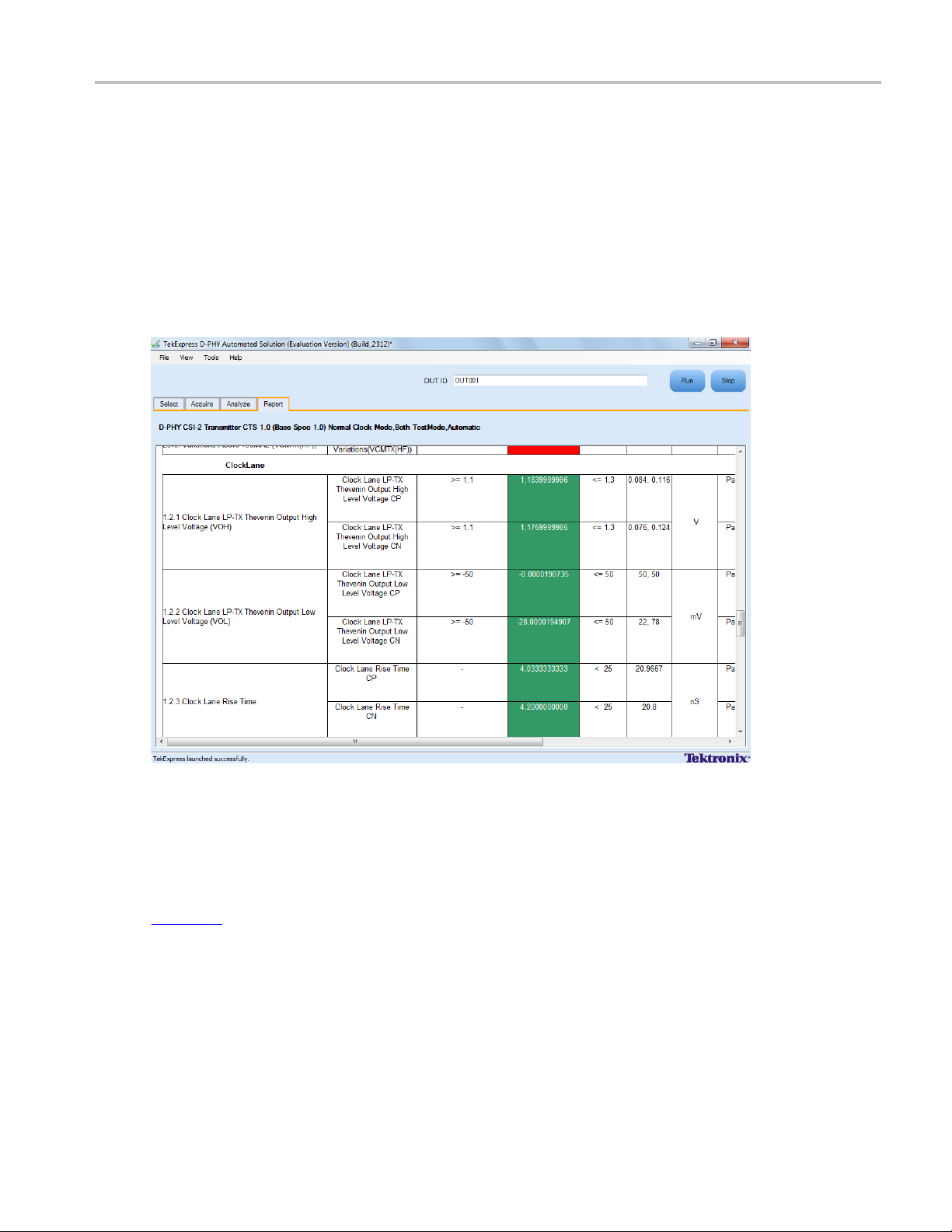
Application Examples View Report for Group 2 Tests
11. Click the Acquire tab to view the acquisition parameters. Select the Data (Dp and Dn) and Clock
(Clkp and Clkn) sources.
12. Click Run to start the test. The Acquire panel shows the progress and status of the test as it runs.
View Report for Group 2 Tests
The application automatically displays a report in the Report panel once the test is successfully completed.
A t able shows the test name, measurement details, test result (pass/fail), compliance mode, and analysis
time. Save the report as an MHT file using the File > Save As option. The following screen shows
the results for Group 2 tests.
Connections for Data Lane HS Entry: Data Lane TLPX Value
Click here for information on connections for the Data Lane HS Entry: Data Lane TLPX Value test.
Configure and Run Data Lane HS Entry: Data Lane TLPX Value
The Data Lane HS Entry: Data Lane TLPX Va lue test is supported on LP-HS waveforms although it is not
recommended to use LP-HS waveforms for this test.
TekExpress D-PHY Automated Solution 67
Page 80

Application Examples Configure and Run Data Lane HS Entry: Data Lane TLPX Value
1. In the Select panel, select the Device.
2. Select the Clock Mode as Normal or Continuous.
NOTE. The Clock mode Continuous is available only when the test mode is Normal.
3. Select Clock Lane Probing as Single-ended.
NOTE. The Data Lane HS Entry: Data Lane TLPX Value test is not available when the selected clock
lane probing is Differential.
4. Select the Test Mode as Escape or Normal.
The Version default value is CTS 1.0.
5. Select the test and click Configure.
6. In the Configuration Panel, set the following parameters for the test (Data and Clock Lanes Acquisition
with Data as Trigger). The following table lists the compliance mode values and the permitted range
of values for the user-defined mode:
Table 34: Configuration parameters for Data Lane HS Entry: Data Lane TLPX Value
Parameter Default User defined mode
Vertical Scale (mV)
Vertical Position for Data (div)
Vertical Position for C lock (div)
Vertical Offset (V)
Horizontal Scale (us)
Sample Rate (GS/s)
Record Length 1000000 100000 to 10000000
xxx
200 50, 100, 200
–2.6 +3 to –3
–2.6 +3 to –3
0 Do not change
8 8, 10, 12
12.5 7.5, 10, 12.5
7. Click Analyze. View and change the following analysis parameters:
Table 35: Analysis parameters for Data Lane HS Entry: Data Lane TLPX Value
Parameter Default User defined mode
Trigger Type Transition Transition
Trigger Source Ch1 Ch1, Ch2, Ch3, Ch4
Trigger Upper Level (V)
Trigger Lower Level V)
Trigger Time (pS)
Trigger Transition
1 Enter a value based on the test
0.05 0.05, 0.1, 1
500 250, 500
Greater Than Greater Than, Less Than
68 TekExpress D-PHY Automated Solution
Page 81

Application Examples Connections for Data Lane HS Entry: THS-PREPARE Value
Table 35: Analysis parameters for Data Lane HS Entry: Data Lane TLPX Value (cont.)
Parameter Default User defined mode
Trigger Slope
Trigger If Violation Occurs Occurs, Logic
xxx
Positive Positive, Negative, Either
8. Click Limits to view and change the Data Lane HS Entry DATA Lane TLP value and the compare
string.
9. Click Comments to enter comments. The comments are shown in the test report.
10. Click Save to effect the changes, or clickCancel.
11. Click the Acquire tab to view the acquisition parameters. Select the Data (Dp and Dn) and Clock
(Clkp and Clkn) sources.
12. Click Run to start the test. The Acquire panel shows the progress and status of the test as it runs.
Connections for Data Lane HS Entry: THS-PREPARE Value
Click here for information on connections for the Data Lane HS Entry: THS-PREPARE Value test.
Configure and Run Data Lane HS Entry: THS-PREPARE Value
1. In the Select panel, select the Device.
2. Select the Clock Mode as Normal or Continuous.
3. Select Clock Lane Probing as Single-ended or Differential.
4. Select the Test Mode as Normal.
The Version default value is CTS 1.0.
5. Select the test and click Configure.
6. In the Configuration Panel, set the following parameters for the test (Data and Clock Lanes Acquisition
with Data as Trigger). The following table lists the compliance mode values and the permitted range
of values for the user-defined mode:
Table 36: Configuration parameters for Data Lane HS Entry: THS-PREPARE Value
Parameter Default User defined mode
Vertical Scale (mV)
Vertical P o sition for D ata (div)
Vertical Position for Clock (div)
Single-ended probing
Differential probing
200 50, 100, 200
–2.6 +3 to –3
–2.6
+2.6
–3 to +3
+3 to –3
TekExpress D-PHY Automated Solution 69
Page 82

Application Examples Configure and Run Data Lane HS Entry: THS-PREPARE Value
Table 36: Configuration parameters for Data Lane HS Entry: THS-PREPARE Value (cont.)
Parameter Default User defined mode
Vertical Offset (V)
Horizontal Scale (us)
Sample Rate (GS/s)
0 Do not change
8 8, 10, 12
12.5 7.5, 10, 12.5
Record Length 1000000 100000 to 10000000
xxx
7. Click Analyze. View and change the following analysis parameters:
Table 37
: Analysis parameters for Data Lane HS Entry: THS-PREPARE Value
Parameter Default User defined mode
rType
Trigge
r Source
Trigge
er Upper Level (V)
Trigg
er Lower Level (V)
Trigg
ger Time (pS)
Trig
Trigger Transition
gger Slope
Tri
igger If Violation
Tr
xxx
tion
Transi
Ch1 Ch1, Ch
Transi
tion
2, Ch3, Ch4
1 Enter a value based on the test
0.05 0.05, 0.1, 1
500 250, 500
ater Than
Gre
ater Than, Less Than
Gre
Positive Positive, Negative, Either
Oc
curs
curs, Logic
Oc
8. Click Limits to view and c hange the Data Lane HS Entry: THS-PREPARE values in ns, and the
compare string.
9. Click Comments to enter comments. The comments are shown in the test report.
10. Click Save to effect the changes, or clickCancel.
11. Click the Acquire tab to view the acquisition parameters. Select the Data (Dp and Dn) and Clock
(Clkp and Clkn) sources.
12. Click Run to start the test. The Acquire panel shows the progress and status of the test as it runs.
70 TekExpress D-PHY Automated Solution
Page 83

Application Examples Connections for Data Lane HS Entry: THS-PREPARE + THS-ZERO Value
Connections for Data Lane HS Entry: THS-PREPARE + THS-ZERO Value
Click here for information on connections for the Data Lane HS Entry: THS-PREPARE + THS-ZERO
Value test.
ConfigureandRunDataLaneHSEntry:THS-PREPARE+THS-ZERO
Value
1. In the Select panel, select the Device.
2. Select the Clock Mode as Normal or Continuous.
3. Select Clock Lane Probing as Single-ended or Differential.
4. Select the Test Mode as Normal.
The Version default value is CTS 1.0.
5. Select the test and click Configure.
6. In the Configuration Panel, set the following parameters for the test (Data and Clock Lanes Acquisition
with Data as Trigger). The following table lists the compliance mode values and the permitted range
of values for the user-defined mode:
Table 38: Configuration parameters for Data Lane HS Entry: THS-PREPARE + THS-ZERO
Parameter Default User defined mode
Vertical Scale (mV)
Vertical P o sition for D ata (div)
Vertical Position for Clock (div)
Single-ended probing
Differential probing
Vertical Offset (V)
Horizontal Scale (us)
Sample Rate (GS/s)
Record Length 1000000 100000 to 10000000
xxx
200 50, 100, 200
–2.6 +3 to –3
–2.6
+2.6
0 Do not change
8 8, 10, 12
12.5 7.5, 10, 12.5
–3 to +3
–3 to –3
7. Click Analyze. View and change the following analysis parameters:
Table 39: Analysis parameters for Data Lane HS Entry: THS-PREPARE + THS-ZERO
Parameter Default User defined mode
Trigger Type Transition Transition
Trigger Source Ch1 Ch1, Ch2, Ch3, Ch4
Trigger Upper Level (V)
1 Enter a value based on the test
TekExpress D-PHY Automated Solution 71
Page 84

Application Examples Connections for Data Lane HS-TX Differential Voltages (VOD(0), VOD(1))
Table 39: Analysis parameters for Data Lane HS Entry: THS-PREPARE + THS-ZERO (cont.)
Parameter Default User defined mode
Trigger Lower Level (V)
Trigger Time (pS)
Trigger Transition
Trigger Slope
Trigger If Violation Occurs Occurs, Logic
xxx
8. Click Limits to view and change the Data Lane HS Entry: THS-PREPARE + THS-ZERO values in
ns, and t
9. Click Comments to enter comments. The comments are shown in the test report.
10. Click Save to effect the changes, or clickCancel.
11. Click the Acquire tab to view the acquisition parameters. Select the Data (Dp and Dn) and Clock
(Clkp and Clkn) sources.
12. Click Run to start the test. The Acquire panel shows the progress and status of the test as it runs.
he compare string.
0.05 0.05, 0.1, 1
500 250, 500
Greater Than Greater Than, Less Than
Positive Positive, Negative, Either
nections for D ata Lane HS-TX Differential Voltages (VOD(0), VOD(1))
Con
ck here
Cli
VOD(1)) Value test.
onfigure and Run Data Lane HS-TX Differential Voltages (VOD(0),
C
OD(1))
V
1.I
2. Select the Clock Mode as Normal or Continuous.
3. Select Clock Lane Probing as Single-ended or Differential.
4. Select the Test Mode as Normal.
The Version default value is CTS 1.0.
5. Select the test and click Configure.
6. In the Configuration Panel, set the following parameters for the test (Data and Clock Lanes Acquisition
with Data as Trigger). The following table lists the compliance mode values and the permitted range
of values for the user-defined mode:
for information on connections for the Data Lane HS-TX Differential Voltages (VOD(0),
n the Select panel, select the Device.
72 TekExpress D-PHY Automated Solution
Page 85

Application Examples Configure and Run Data Lane HS-TX Differential Voltages (VOD(0), VOD(1))
Table 40: Configuration parameters for Data Lane HS-TX Differential Voltages (VOD(0), VOD(1))
Parameter Default User defined mod
Vertical Scal
Vertical Pos
Vertical Pos
e(mV)
ition for Data (div)
ition for Clock (div)
Single-ended probing
Differential probing
Vertical Offset (V)
Horizontal Scale (us)
Sample Rate (GS/s)
200 50, 100, 200
–2.6 +3 to –3
–2.6
+2.6
+3 to –3
–3 to +3
0 Do not change
8 8, 10, 12
12.5 7.5, 10, 12.5
e
Record Length 1000000 100000 to 10000000
xxx
7. Click Analyze. View and change the following analysis parameters:
Table 41: Analysis parameters for Data Lane HS-TX Differential Voltages (VOD(0), VOD(1))
Parameter Default User defined mode
Trigger Type Transition Transition
Trigger Source Ch1 Ch1, Ch2, Ch3, Ch4
Trigger Upper Level (V)
Trigger Lower Level (V)
Trigger Time (pS)
Trigger Transition
Trigger Slope
1 Enter a value based on the test
0.05 0.05, 0.1, 1
500 250, 500
Greater Than Greater Than, Less Than
Positive Positive, Negative, Either
Trigger If Violation Occurs Occurs, Logic
xxx
8. Click Limits to view and change the VOD(1) and VOD(0) values in mV, and the compare string.
9. Click Comments to enter comments. The comments are shown in the test report.
10. Click Save to effect the changes, or clickCancel.
11. Click the Acquire tab to view the acquisition parameters. Select the Data (Dp and Dn) and Clock
(Clkp and Clkn) sources.
12. Click Run to start the test. The Acquire panel shows the progress and status of the test as it runs.
TekExpress D-PHY Automated Solution 73
Page 86

Application Examples Connections for Data Lane HS-TX Differential Voltage Mismatch (VOD)
Connections for Data Lane HS-TX Differential Voltage Mismatch (VOD)
Click here for information on connections for the Data Lane HS-TX Differential Voltage Mismatch
(VOD) Value test.
Configure and Run Data Lane HS-TX Differential Voltage Mismatch (VOD)
1. In the Select panel, select the Device.
2. Select the Clock Mode as Normal or Continuous.
3. Select Clock Lane Probing as Differential.
4. Select the Test Mode as Normal.
The Version default value is CTS 1.0.
5. Select the test and click Configure.
6. In the Configuration Panel, set the following parameters for the test (Data and Clock Lanes Acquisition
with Data as Trigger). The following table lists the compliance mode values and the permitted range
of values for the user-defined mode:
Table 42: Configuration parameters for D ata Lane HS-TX Differential Voltage Mismatch (V
Parameter Default User defined mode
Vertical Scale (mV)
Vertical Position for Data (div)
Vertical Position for C lock (div)
Single-ended probing
Differential probing
Vertical Offset (V)
Horizontal Scale (us)
Sample Rate (GS/s)
Record Length 1000000 100000 to 10000000
xxx
200 50, 100, 200
–2.6 +3 to –3
+2.6 –3 to +3
0 Do not change
8 8, 10, 12
12.5 7.5, 10, 12.5
OD)
7. Click Analyze. View and change the following analysis parameters:
Table 43: Analysis parameters for Data Lane HS-TX Differential Voltage Mismatch (VOD)
Parameter Default User defined mode
Trigger Type Transition Transition
Trigger Source Ch1 Ch1, Ch2, Ch3, Ch4
Trigger Upper Level (V)
Trigger Lower Level (V)
1 Enter a value based on the test
0.05 0.05, 0.1, 1
74 TekExpress D-PHY Automated Solution
Page 87

Application Examples Connections for Data Lane
HS-TX Single-E
Table 43: Analysis parameters for Data Lane HS-TX Differential Voltage Mismatch (VOD) (cont.)
Parameter Default User defined mode
Trigger Time (pS)
Trigger Transition
Trigger Slope
Trigger If Violation Occurs Occurs, Logic
xxx
8. Click Limits to view and change the VOD values in mV, and t he compare string.
9. Click Comments to enter comments. The comments are shown in the test report.
10. Click Save to effect the changes, or clickCancel.
11. Click the Acquire tab to view the acquisition parameters. Select the Data (Dp and Dn) and Clock
(Clkp and Clkn) sources.
12. Click Run to start the test. The Acquire panel shows the progress and status of the test as it runs.
500 250, 500
Greater Than Greater Than, Less Than
Positive Positive, Negative, Either
nded Output High Voltages ((VOHHS(DP), VOHHS(DN))
Connections for Data Lane HS-TX Single-Ended Output High Voltages
((VOHHS(DP), VOHHS(DN))
Click here for information on connections for the Data Lane HS-TX Single-Ended Output High Voltages
OHHS(DP), VOHHS(DN)) test.
((V
Configure and Run Data Lane HS-TX Single-Ended Output High Voltages
((VOHHS(DP), VOHHS(DN))
1. In the Select panel, select the Device.
2. Select the Clock Mode as Normal or Continuous.
3. Select Clock Lane Probing as Single-ended.
4. Select the Test Mode as Normal.
The Version default value is CTS 1.0.
5. Select the test and click Configure.
6. In the Configuration Panel, set the following parameters for the test (Data and Clock Lanes Acquisition
with Data as Trigger). The following table lists the compliance mode values and the permitted range
of values for the user-defined mode:
TekExpress D-PHY Automated Solution 75
Page 88

Application Examples Configure and Run Data Lane
HS-TX Single-E
nded Output High Voltages ((VOHHS(DP), VOHHS(DN))
Table 44: Configuration parameters for Data Lane HS-TX Single-Ended Output High Voltages ((VOHHS(DP),
VOHHS(DN))
Parameter Default User defined mode
Vertical Scale (mV)
Vertical Position for Data (div)
Vertical Position for C lock (div)
Vertical Offset (V)
Horizontal Scale (us)
Sample Rate (GS/s)
200 50, 100, 200
–2.6 +3 to –3
–2.6 +3 to –3
0 Do not change
8 8, 10, 12
12.5 7.5, 10, 12.5
Record Length 1000000 100000 to 10000000
xxx
7. Click Analyze. View and change the following analysis parameters:
Table 45: Analysis parameters for Data Lane HS-TX Single-Ended Output High Voltages ((VOHHS(DP),
VOHHS(DN))
Parameter Default User defined mode
Trigger Type Transition Transition
Trigger Source Ch1 Ch1, Ch2, Ch3, Ch4
Trigger Upper Level (V)
Trigger Lower Level (V)
Trigger Time (pS)
Trigger Transition
Trigger Slope
1 Enter a value based on the test
0.05 0.05, 0.1, 1
500 250, 500
Greater Than Greater Than, Less Than
Negative Positive, Negative, Either
Trigger If Violation Occurs Occurs, Logic
xxx
8. Click Limits to view and change the Data Lane HS-TX Single-Ended Output High Voltages DP
and DN values in mV, and the compare string.
9. Click Comments to enter comments. The comments are shown in the test report.
10. Click Save to effect the changes, or clickCancel.
11. Click the Acquire tab to view the acquisition parameters. Select the Data (Dp and Dn) and Clock
(Clkp and Clkn) sources.
12. Click Run to start the test. The Acquire panel shows the progress and status of the test as it runs.
76 TekExpress D-PHY Automated Solution
Page 89

Application Examples Connections for
Data Lane HS-TX
Static Common-Mode Voltages (VCMTX(1), VCMTX(0))
Connections for Data Lane HS-TX Static Common-Mode Voltages
(VCMTX(1), VCMTX(0))
Click here for information on connections for the Data Lane HS-TX Static Common-Mode Voltages
(VCMTX(1), VCMTX(0)) test.
Configure and Run Data Lane HS-TX Static Common-Mode Voltages
(VCMTX(1), VCMTX(0))
1. In the Select panel, select the Device.
2. Select the Clock Mode as Normal or Continuous.
3. Select Clock Lane Probing as Single-ended or Differential.
4. Select the Test Mode as Normal.
The Vers
ion default value is CTS 1.0.
5. Select the test and click Configure.
6. In the Configuration Panel, set the following parameters for the test (Data and Clock Lanes Acquisition
with Data as Trigger). The following table lists the compliance mode values and the permitted range
ues for the user-defined mode:
of val
Table 46: Configuration parameters for Data Lane HS-TX Static Common-Mode Voltages (VCMTX(1),
VCMTX(0))
meter
Para
tical Scale (mV)
Ver
tical Position for Data (div)
Ver
rtical Position for Clock (div)
Ve
Single-ended probing
Differential probing
Vertical Offset (V)
Horizontal Scale (us)
Sample Rate (GS/s)
Record Length 1000000 100000 to 10000000
xxx
ult
Defa
200 50, 100, 200
–2.6 +3 to –3
.6
–2
+2.6
0Do
88
12.5 7.5, 10, 12.5
defined mode
User
to –3
+3
–3 to +3
not change
, 10, 12
7. Click Analyze. View and change the following analysis parameters:
TekExpress D-PHY Automated Solution 77
Page 90

Application Examples Connections for Data Lane HS-TX Static Common-Mode Voltage Mismatch (VCMTX(1,0))
Table 47: Analysis parameters for Data Lane HS-TX Static Common-Mode Voltages (VCMTX(1), VCMTX(0))
Parameter Default User defined mod
Trigger Type Transition Transition
Trigger Source Ch1 Ch1, Ch2, Ch3, Ch4
Trigger Upper Level (V)
Trigger Lower Level (V)
Trigger Time (pS)
Trigger Transition
Trigger Slope
Trigger If Violation Occurs Occurs, Logic
xxx
8. Click Li
and the compare string.
9. Click C
10. Click Save to effect the changes, or clickCancel.
11. Click the Acquire tab to view the acquisition parameters. Select the Data (Dp and Dn) and Clock
(Clkp and Clkn) sources.
12. Click Run to start the test. The Acquire panel shows the progress and status of the test as it runs.
mits to view and change the Common Mode Voltages VTX(0) and VTX(1) values in mV,
omments to enter comments. The comments are shown in the test report.
1 Enter a value based on the test
0.05 0.05, 0.1, 1
500 250, 500
Greater Than Greater Than, Less Than
Negative Positive, Negative, Either
e
Connections for Data Lane HS-TX Static Common-Mode Voltage
Mismatch (VCMTX(1,0))
Click here for information on connections for the Data Lane HS-TX Static Common-Mode Voltage
Mismatch (VCMTX(1,0)) test
Configure and Run Data Lane HS-TX Static Common-Mode Voltage
Mismatch (VCMTX(1,0))
1. In the Select panel, select the Device.
2. Select the Clock Mode as Normal or Continuous.
3. Select Clock Lane Probing as Single-ended or Differential.
4. Select the Test Mode as Normal.
The Version default value is CTS 1.0.
5. Select the test and click Configure.
78 TekExpress D-PHY Automated Solution
Page 91

Application Examples Configure and Run
Data Lane HS-TX
Static Common-Mode Voltage Mismatch (VCMTX(1,0))
6. In the Configuration Panel, set the following parameters for the test (Data and Clock Lanes Acquisition
with Data as Trigger). The following table lists the compliance mode values and the permitted range
of values for t
he user-defined mode:
Table 48: Configuration parameters for Data Lane HS-TX Static Common-Mode Voltage Mismatch (VCMTX(1,0))
Parameter Default User defined mode
Vertical Scale (mV)
Vertical P o sition for D ata (div)
Vertical Position for Clock (div)
Single-ended probing
Differential probing
Vertical Offset (V)
Horizontal Scale (us)
Sample Rate (GS/s)
Record Length 1000000 100000 to 10000000
xxx
200 50, 100, 200
–2.6 +3 to –3
–2.6
+2.6
0 Do not change
8 8, 10, 12
12.5 7.5, 10, 12.5
+3 to –3
–3 to +3
7. Click Analyze. View and change the following analysis parameters:
49: Analysis parameters for Data Lane HS-TX Static Common-Mode Voltage Mismatch (VCMTX(1,0))
Table
Parameter Default User defined mode
ger Type
Trig
ger Source
Trig
gger Upper Level (V)
Tri
gger Lower Level (V)
Tri
igger Time (pS)
Tr
Trigger Transition
rigger Slope
T
Trigger If Violation Occurs Occurs, Logic
xxx
sition
Tran
Ch1 Ch1,
1 Enter a value based on the test
0.05 0.05, 0.1, 1
500 250, 500
reater Than
G
Negative Positive, Negative, Either
sition
Tran
Ch2, Ch3, Ch4
reater Than, Less Than
G
8. Click Limits to view and change the Common Mode Voltage Mismatch values in mV, and the
compare string.
9. Click Comments to enter comments. The comments are shown in the test report.
10. Click Save to effect the changes, or clickCancel.
11. Click the Acquire tab to view the acquisition parameters. Select the Data (Dp and Dn) and Clock
(Clkp and Clkn) sources.
12. Click Run to start the test. The Acquire panel shows the progress and status of the test as it runs.
TekExpress D-PHY Automated Solution 79
Page 92

Application Examples Connections for Data Lane
HS-TX Dynamic C
ommon-Level Variations Between 50-450MHz (VCMTX(LF))
Connections for Data Lane HS-TX Dynamic Common-Level Variations
Between 50-450MHz (VCMTX(LF))
Click here for information on connections for the Data Lane HS-TX Dynamic Common-Level Variations
Between 50-450MHz (VCMTX(LF)) test
Configure and Run Data Lane HS-TX Dynamic Common-Level Variations
Between 50-450MHz (VCMTX(LF))
The Data Lane HS-TX Dynamic Common-Level Variations Between 50-450MHz (VCMTX(LF)) test
uses a band pass filter. To perform the measurement, the appli
(unfiltered) and the filtered waveform as follows:
1. Acquires unfiltered waveforms from the oscilloscope channels. Typical waveform names
are like
Filter_Lane1_DN.wfm
BandPass Filter_Lane1_DP.wfm
Acq1_Data Lanes Acquisition with Data As Trigger and BandPass
and Acq1 _Data Lanes Acquisition with Data As Trigger and
.
cation uses both the original waveform
2. Applies a band pass filter on live channels and stores them on the Math channel. Typical filtered
waveform file name are like
Filter_DN.WFM
ter_DP.WFM
3. Saves both Live and Math waveforms to the disk.
4. Performs the measurement using both the Live
In the pre-recorded mode, it is enough if you to select the unfiltered waveforms. However, make sure
that the filtered waveforms are in the same folder as the unfiltered w aveforms for these measurements
to run correctly in pre-recorded mode. The filtered waveforms for the measurements must be the ones
saved by the TekExpress application. The measurements will not work as expected if any other filtered
waveforms are used. .
1. In the Select panel, select the Device.
2. Select the Clock Mode as Normal or Continuous.
3. Select Clock Lane Probing as Single-ended or Differential.
4. Select the Test Mode as Normal.
The Version default value is CTS 1.0.
5. Select the test and click Configure.
6. In the Configuration Panel, set the following parameters for the test (Data Lanes Acquisition with
Data as Trigger and BandPass Filter). The following table lists the compliance mode values and the
permitted range of values for the user-defined mode:
and Lane1_FilteredTwoChannelwithDataasTriggerAndBandPassFil-
.
Lane1_FilteredTwoChannelwithDataasTriggerAndBandPass-
and Math waveforms.
80 TekExpress D-PHY Automated Solution
Page 93

Application Examples Configure and Run Data Lane
HS-TX Dynamic C
ommon-Level Variations Between 50-450MHz (VCMTX(LF))
Table 50: Configuration parameters for Data Lane HS-TX Dynamic Common-Level Variations Between
50-450MHz (VCMTX(LF))
Parameter Default User defined mode
Vertical Scale (mV)
Vertical P o sition for D ata (div)
200 100, 200, 300
–2.6 +3 to –3
Vertical Position for Clock (div)
Single-ended probing
Differential probing
Vertical Offset (V)
Horizontal Scale (us)
Sample Rate (GS/s)
–2.6
+2.6
0 Do not change
8 8, 10, 12
12.5 7.5, 10, 12.5
+3 to –3
–3 to +3
Record Length 1000000 100000 to 10000000
xxx
7. Click Analyze. View and change the following analysis parameters:
Table 51: Analysis parameters for Data Lane HS-TX Dynamic Common-Level Variations Between 50-450MHz
(VCMTX(LF))
Parameter Default User defined mode
Trigger Type Transition Transition
Trigger Source Ch1 Ch1, Ch2, Ch3, Ch4
Trigger Upper Level (V)
Trigger Lower Level (V)
Trigger Time (pS)
Trigger Transition
Trigger Slope
1 Enter a value based on the test
0.05 0.05, 0.1, 1
500 250, 500
Greater Than Greater Than, Less Than
Negative Positive, Negative, Either
Trigger If Violation Occurs Occurs, Logic
xx
x
8. Click Limits to view and change the Data Lane HS-TX Dynamic Common-Level Variations value in
mV, and the compare string.
9. Click Comments to enter comments. The comments are shown in the test report.
10. Click Save to effect the changes, or clickCancel.
11. Click the Acquire tab to view the acquisition parameters. Select the Data (Dp and Dn) and Clock
(Clkp and Clkn) sources.
12. Click Run to start the test. The Acquire panel shows the progress and status of the test as it runs.
TekExpress D-PHY Automated Solution 81
Page 94

Application Examples Connections for Data Lane
HS-TX Dynamic C
ommon-Level Variations Above 450MHz (VCMTX(HF))
Connections for Data Lane HS-TX Dynamic Common-Level Variations
Above 450MHz (VCMTX(HF))
Click here for information on connections for the Data Lane HS-TX Dynamic Common-Level Variations
Above 450MHz (VCMTX(HF)) test
Configure and Run Data Lane HS-TX Dynamic Common-Level Variations
Above 450MHz (VCMTX(HF))
The Data Lane HS-TX Dynamic Common-Level Variations Above 450MHz (VCMTX(LF)) test uses a
high pass filter. To perform the measurement, the applicatio
and the filtered waveform as follows:
1. Acquires unfiltered waveforms from the oscilloscope channels. Typical waveform names
are like
Filter_Lane1_DN.wfm
HighPass Filter_Lane1_DP.wfm
Acq2_Data Lanes Acquisition with Data As Trigger and HighPass
and Acq2 _Data Lanes Acquisition with Data As Trigger and
.
n uses both the original waveform (unfiltered)
2. Applies a high pass filter on live channels and stores them on the Math channel. Typical filtered
waveform file names are like
PassFilter_DN.WFM
Filter_DP.WFM
3. Saves both Live and Math waveforms to the disk.
4. Performs the measurement using both the Live
In the pre-recorded mode, it is enough if you to select the unfiltered waveforms. However, make sure
that the filtered waveforms are in the same folder as the unfiltered w aveforms for these measurements
to run correctly in pre-recorded mode. The filtered waveforms for the measurements must be the ones
saved by the TekExpress application. The measurements will not work as expected if any other filtered
waveforms are used. .
1. In the Select panel, select the Device.
2. Select the Clock Mode as Normal or Continuous.
3. Select Clock Lane Probing as Single-ended or Differential.
4. Select the Test Mode as Normal.
The Version default value is CTS 1.0.
5. Select the test and click Configure.
6. In the Configuration Panel, set the following parameters for the test (Data Lanes Acquisition with
Data as Trigger and HighPass Filter). The following table lists the compliance mode values and the
permitted range of values for the user-defined mode:
.
Lane1_FilteredTwoChannelwithDataasTriggerAndHigh-
and Lan e1_FilteredTwoChannelwithDataasTriggerAndHighPass-
and Math waveforms.
82 TekExpress D-PHY Automated Solution
Page 95

Application Examples Configure and Run Data Lane
HS-TX Dynamic C
ommon-Level Variations Above 450MHz (VCMTX(HF))
Table 52: Configuration parameters for Data Lane HS-TX Dynamic Common-Level Variations Above 450MHz
(VCMTX(HF))
Parameter Default User defined mode
Vertical Scale (mV)
Vertical P o sition for D ata (div)
200 100, 200, 300
–2.6 +3 to –3
Vertical Position for Clock (div)
Single-ended probing
Differential probing
Vertical Offset (V)
Horizontal Scale (us)
Sample Rate (GS/s)
–2.6
+2.6
0 Do not change
8 8, 10, 12
12.5 7.5, 10, 12.5
+3 to –3
–3 to +3
Record Length 1000000 100000 to 10000000
xxx
7. Click Analyze. View and change the following analysis parameters:
Table 53: Analysis parameters for Data Lane HS-TX Dynamic Common-Level Variations Above 450MHz
(VCMTX(HF))
Parameter Default User defined mode
Trigger Type Transition Transition
Trigger Source Ch1 Ch1, Ch2, Ch3, Ch4
Trigger Upper Level (V)
Trigger Lower Level (V)
Trigger Time (pS)
Trigger Transition
Trigger Slope
1 Enter a value based on the test
0.05 0.05, 0.1, 1
500 250, 500
Greater Than Greater Than, Less Than
Negative Positive, Negative, Either
Trigger If Violation Occurs Occurs, Logic
xx
x
8. Click Limits to view and change the Data Lane HS-TX Dynamic Common-Level Variations value in
mV, and the compare string.
9. Click Comments to enter comments. The comments are shown in the test report.
10. Click Save to effect the changes, or clickCancel.
11. Click the Acquire tab to view the acquisition parameters. Select the Data (Dp and Dn) and Clock
(Clkp and Clkn) sources.
12. Click Run to start the test. The Acquire panel shows the progress and status of the test as it runs.
TekExpress D-PHY Automated Solution 83
Page 96

Application Examples Connections for Data Lane HS-TX 20%-80% Rise time (tR)
Connections for Data Lane HS-TX 20%-80% Rise time (tR)
Click here for information on connections for the Data Lane HS-TX 20%-80% Rise time (tR) test.
Configure and Run Data Lane HS-TX 20%-80% Rise time (tR)
1. In the Select panel, select the Device.
2. Select the Clock Mode as Normal or Continuous.
3. Select Clock Lane Probing as Single-ended or Differential.
4. Select the Test Mode as Normal.
The Version default value is CTS 1.0.
5. Select the test and click Configure.
6. In the Configuration Panel, set the following parameters for the test (Data and Clock Lanes Acquisition
with Data as Trigger). The following table lists the compliance mode values and the permitted range
of values for the user-defined mode:
Table 54: Co nfiguration parameters for Data LaneHS-TX20%-80%Risetime(tR)
Parameter Default User defined mode
Vertical Scale (mV)
Vertical Position for Data (div)
Vertical Position for C lock (div)
Single-ended probing
Differential probing
Vertical Offset (V)
Horizontal Scale (us)
Sample Rate (GS/s)
Record Length 1000000 100000 to 10000000
xxx
200 50, 100, 200
–2.6 +3 to –3
–2.6
+2.6
0 Do not change
8 8, 10, 12
12.5 7.5, 10, 12.5
+3 to –3
–3 to +3
7. Click Analyze. View and change the following analysis parameters:
Table 55: Analysis parameters for Data Lane HS-TX 20%-80% R ise time (tR)
Parameter Default User defined mode
Trigger Type Transition Transition
Trigger Source Ch1 Ch1, Ch2, Ch3, Ch4
Trigger Upper Level (V)
Trigger Lower Level (V)
Trigger Time (pS)
1 Enter a value based on the test
0.05 0.05, 0.1, 1
500 250, 500
84 TekExpress D-PHY Automated Solution
Page 97

Application Examples Connections for Data Lane HS-TX 80%-20% Fall time (tF)
Table 55: Analysis parameters for Data Lane HS-TX 20%-80% Rise time (tR) (cont.)
Parameter Default User defined mode
Trigger Transition
Trigger Slope
Trigger If Violation Occurs Occurs, Logic
xxx
Greater Than Greater Than, Less Than
Positive Positive, Negative, Either
8. Click Limits to view and change the tR value in pS, and the compare string.
9. Click Comments to enter comments. The comments are shown in the test report.
10. Click Save to effect the changes, or clickCancel.
11. Click the Acquire tab to view the acquisition parameters. Select the Data (Dp and Dn) and Clock
(Clkp and Clkn) sources.
12. Click Run to start the test. The Acquire panel shows the progress and status of the test as it runs.
Connections for Data Lane HS-TX 80%-20% Fall time (tF)
Click here for information on connections for the Data Lane HS-
TX 80%-20% Fall time (tF) test.
Configure and Run Data Lane HS-TX 80%-20% Fall time (tF)
1. In the Select panel, select the Device.
2. Select the Clock Mode as Normal or Continuous.
3. Select Clock Lane Probing as Single-ended or Differential.
4. Select the Test Mode as Normal.
The Version default value is CTS 1.0.
5. Select the test and click Configure.
6. In the Configuration Panel, set the following parameters for the test (Data and Clock Lanes Acquisition
with Data as Trigger). The following table lists the compliance mode values and the permitted range
of values for the user-defined mode:
Table 56: Configuration parameters for Data Lane HS-TX 80%-20% Fall time (tF)
Parameter Default User defined mode
Vertical Scale (mV)
Vertical P o sition for D ata (div)
Vertical Position for Clock (div)
Single-ended probing
Differential probing
200 50, 100, 200
–2.6 +3 to –3
–2.6
+2.6
+3 to –3
–3 to +3
TekExpress D-PHY Automated Solution 85
Page 98

Application Examples Connections for Data Lane HS Exit: THS-TRAIL Value
Table 56: Configuration parameters for Data Lane HS-TX 80%-20% Fall time (tF) (cont.)
Parameter Default User defined mode
Vertical Offset (V)
Horizontal Scale (us)
Sample Rate (GS/s)
Record Length 1000000 100000 to 10000000
xxx
0 Do not change
8 8, 10, 12
12.5 7.5, 10, 12.5
7. Click Analyze. View and change the following analysis parameters:
57: Analysis parameters for Data Lane HS-TX 80%-20% Fall time (tF)
Table
Parameter Default User defined mode
ger Type
Trig
ger Source
Trig
gger Upper Level (V)
Tri
gger Lower Level (V)
Tri
igger Time (pS)
Tr
Trigger Transition
rigger Slope
T
Trigger If Violation Occurs Occurs, Logic
xxx
sition
Tran
Ch1 Ch1,
1 Enter a value based on the test
0.05 0.05, 0.1, 1
500 250, 500
reater Than
G
Positive Positive, Negative, Either
sition
Tran
Ch2, Ch3, Ch4
reater Than, Less Than
G
8. Click Limits to view and change the tF values in pS, and the compare string.
9. Click Comments to enter comments. The comments are shown in the test report.
10. Click Save to effect the changes, or clickCancel.
11. Click the Acquire tab to view the acquisition parameters. Select the Data (Dp and Dn) and Clock
(Clkp and Clkn) sources.
12. Click Run to start the test. The Acquire panel shows the progress and status of the test as it runs.
Connections for Data Lane HS Exit: THS-TRAIL Value
Click here for information on connections for the Data Lane HS Exit: THS-TRAIL Value test.
Configure and Run Data Lane HS Exit: THS-TRAIL Value
1. In the Select panel, select the Device.
2. Select the Clock Mode as Normal or Continuous.
3. Select Clock Lane Probing as Single-ended or Differential.
86 TekExpress D-PHY Automated Solution
Page 99

Application Examples Configure and Run Data Lane HS Exit: THS-TRAIL Value
4. Select the Test Mode as Normal.
The Version default value is CTS 1.0.
5. Select the test and click Configure.
6. In the Configuration Panel, set the following parameters for the test (Data and Clock Lanes Acquisition
with Data as Trigger). The following table lists the compliance mode values and the permitted range
of values for the user-defined mode:
Table 58: Configuration parameters for Data Lane HS Exit: THS-TRAIL Value
Parameter Default User defined mode
Vertical Scale (mV)
Vertical P o sition for D ata (div)
Vertical Position for Clock (div)
Single-ended probing
Differential probing
Vertical Offset (V)
Horizontal Scale (us)
Sample Rate (GS/s)
Record Length 1000000 100000 to 10000000
xxx
200 50, 100, 200
–2.6 +3 to –3
–2.6
+2.6
0 Do not change
8 8, 10, 12
12.5 7.5, 10, 12.5
+3 to –3
–3 to +3
7. Click Analyze. View and change the following analysis parameters:
Table 59: Analysis parameters for Data Lane HS Exit: THS-TRAIL Value
Parameter Default User defined mode
Trigger Type Transition Transition
Trigger Source Ch1 Ch1, Ch2, Ch3, Ch4
Trigger Upper Level (V)
Trigger Lower Level (V)
Trigger Time (pS)
Trigger Transition
Trigger Slope
Trigger If Violation Occurs Occurs, Logic
xxx
1 Enter a value based on the test
0.05 0.05, 0.1, 1
500 250, 500
Greater Than Greater Than, Less Than
Positive Positive, Negative, Either
8. Click Limits to view and change the Data Lane THS-TRAIL values in nS, and the compare string.
9. Click Comments to enter comments. The comments are shown in the test report.
10. Click Save to effect the changes, or clickCancel.
11. Click the Acquire tab to view the acquisition parameters. Select the Data (Dp and Dn) and Clock
(Clkp and Clkn) sources.
12. Click Run to start the test. The Acquire panel shows the progress and status of the test as it runs.
TekExpress D-PHY Automated Solution 87
Page 100

Application Examples Connections for Data Lane HS Exit: 30%-80% Post-EOT Rise Test (TREOT)
Connections for Data Lane HS Exit: 30%-80% Post-EOT Rise Test
(TREOT)
Click here for information on connections for the Data Lane HS Exit: 30%–80% Post-EOT Rise Test
(TREOT) test.
Configure and Run Data Lane HS Exit: 30%-80% Post-EOT Rise Test
(TREOT)
1. In the Select panel, select the Device.
2. Select the Clock Mode as Normal or Continuous.
3. Select Clock Lane Probing as Single-ended or Differential.
4. Select the Test Mode as Normal.
The Version default value is CTS 1.0.
5. Select the test and click Configure.
6. In the Configuration Panel, set the following parameters for the test (Data and Clock Lanes Acquisition
with Data as Trigger). T
he following table lists the compliance mode values and the permitted range
of values for the user-defined mode:
Table 60: Configuration parameters for Data Lane HS Exit: 30%-80% Post-EOT Rise Test (TREOT)
Parameter Default User defined mode
Vertical Scale (mV)
Vertical Position fo
Vertical Position f
Single-ended probing
Differential probing
Vertical Offset (V)
Horizontal Scale (us)
Sample Rate (GS/s)
Record Length 1000000 100000 to 10000000
xxx
r Data (div)
or Clock (div)
200 50, 100, 200
–2.6 +3 to –3
–2.6
+2.6
0 Do not change
8 8, 10, 12
12.5 7.5, 10, 12.5
+3 to –3
–3 to +3
7. Click Analyze. View and change the following analysis parameters:
Table 61: Analysis parameters for Data Lane HS Exit: 30%-80% Post-EOT Rise Test (TREOT)
Parameter Default User defined mode
Trigger Type Transition Transition
Trigger Source Ch1 Ch1, Ch2, Ch3, Ch4
88 TekExpress D-PHY Automated Solution
 Loading...