

Page 1

TekExpress® DisplayPort 2.0
Automated Solution
Application Help
*P077170801*
077-1708-01
Page 2

Page 3

TekExpress® DisplayPort 2.0
Automated Solution
Application Help
Register now!
Click the following link to protect your product.
www.tek.com/register
*P077170801*
077-1708-01
Page 4

Copyright © Tektronix. All rights reserved. Licensed software products are owned by Tektronix or its subsidiaries or suppliers, and are
protected by national copyright laws and international treaty provisions. Tektronix products are covered by U.S. and foreign patents, issued
and pending. Information in this publication supersedes that in all previously published material. Specifications and price change privileges
reserved.
TEKTRONIX and TEK are registered trademarks of Tektronix, Inc.
Contacting Tektronix
Tektronix, Inc.
14150 SW Karl Braun Drive
P.O. Box 500
Beaverton, OR 97077
USA
For product information, sales, service, and technical support:
• In North America, call 1-800-833-9200.
• Worldwide, visit to www.tek.com find contacts in your area.
Page 5

Table of Contents
Table of Contents
Welcome....................................................................................................................................................................................... 8
Key features...........................................................................................................................................................................9
Getting help and support.............................................................................................................................................................10
Product documents.............................................................................................................................................................. 10
Conventions......................................................................................................................................................................... 10
Technical support................................................................................................................................................................. 11
Getting started.............................................................................................................................................................................12
Hardware requirements....................................................................................................................................................... 12
Compatibility................................................................................................................................................................. 12
Minimum system requirements.....................................................................................................................................12
Supported probes......................................................................................................................................................... 13
Software requirements.........................................................................................................................................................13
Downloading and installing the software.......................................................................................................................13
Activate the license.......................................................................................................................................................13
View software version and license key details..............................................................................................................14
Setting up the test environment.................................................................................................................................................. 15
About setting up tests.......................................................................................................................................................... 15
Equipment connection setup................................................................................................................................................16
Individual test configuration................................................................................................................................................. 18
About running tests.............................................................................................................................................................. 18
Before you click start............................................................................................................................................................18
Pre-Run checklist.................................................................................................................................................................20
Run a test in pre-recorded mode......................................................................................................................................... 20
Starting the application................................................................................................................................................................22
Application controls..............................................................................................................................................................23
Options menu functions....................................................................................................................................................... 25
Configure email settings............................................................................................................................................... 26
TekExpress instrument control settings........................................................................................................................ 27
Setup panel: Configure the test setup.........................................................................................................................................28
DUT: Set DUT settings.........................................................................................................................................................29
Test Selection: Select the tests............................................................................................................................................ 34
Acquisitions: Set waveform acquisition settings.................................................................................................................. 35
Set acquisition tab parameters..................................................................................................................................... 36
Use pre-recorded waveforms for analysis.................................................................................................................... 36
Running measurements using pre-recorded waveforms.............................................................................................. 37
Acquire live waveforms for analysis..............................................................................................................................38
Configuration: Set measurement limits for tests.................................................................................................................. 40
Preferences: Set the test run preferences........................................................................................................................... 42
Status panel: View the test execution status...............................................................................................................................44
View test execution status....................................................................................................................................................44
View test execution logs.......................................................................................................................................................45
Results panel: View summary of test results...............................................................................................................................47
Filter the test results.............................................................................................................................................................47
Reports panel: Configure report generation settings.................................................................................................................. 48
TekExpress® DisplayPort 2.0 Automated Solution 5
Page 6

Table of Contents
Select report generation options.......................................................................................................................................... 48
View a generated report.......................................................................................................................................................51
Saving and recalling test setup................................................................................................................................................... 52
Test setup files overview...................................................................................................................................................... 52
Save the configured test setup............................................................................................................................................ 52
Load a saved test setup.......................................................................................................................................................52
Select a pre-run session from the loaded test setup............................................................................................................52
Save the test setup with a different name............................................................................................................................53
SCPI Commands........................................................................................................................................................................ 54
About SCPI command......................................................................................................................................................... 54
Socket configuration for SCPI commands........................................................................................................................... 54
Set or query the device name of application........................................................................................................................60
Set or query the DUTID of application................................................................................................................................. 60
Set or query the suite name of the application.....................................................................................................................61
Set or query the test name of the application...................................................................................................................... 61
Set or query the version name of the application.................................................................................................................62
Set or query the general parameter values..........................................................................................................................63
Set or query the acquire parameter values..........................................................................................................................68
Set or query the analyze parameter values......................................................................................................................... 68
Query the available devices in the DUT panel of the application.........................................................................................69
Query the available suites for the selected device...............................................................................................................69
Query the list of available tests of the application................................................................................................................70
Query the available version names of the application......................................................................................................... 72
Query the list of available instruments based on the specified instrument type...................................................................72
Set or query the IP address of the instrument based on the specified instrument type.......................................................72
Query the information of the generated report file............................................................................................................... 73
Query the information of the generated waveform files....................................................................................................... 73
Query the information of the generated image files............................................................................................................. 74
Query the active TekExpress application name................................................................................................................... 74
Sets or query the acquire mode status................................................................................................................................ 74
Set or query the execution mode status.............................................................................................................................. 75
Generate the report for the current session......................................................................................................................... 75
Query the value of specified report header field in the report.............................................................................................. 75
Query the value of specified result detail available in report summary/details table............................................................76
Restore the setup to default settings................................................................................................................................... 77
Save the settings to a specified session.............................................................................................................................. 77
Open the setup from a specified session.............................................................................................................................77
Query the current setup file name........................................................................................................................................78
Run/stop/pause/resume the selected measurements execution in the application............................................................. 78
Query the current measurement execution status............................................................................................................... 78
Query whether the current setup is saved or not saved...................................................................................................... 79
Query the status of the previous command execution.........................................................................................................79
Query the last error occurred............................................................................................................................................... 79
Set or query the popup details............................................................................................................................................. 79
Set or query the View report after generating option status.................................................................................................80
Set or query the enable/disable status of Verbose function.................................................................................................81
Set or query the waveform file recalled for the specified test name and acquire type.........................................................81
Sets or query the limit values in the limits editor window.....................................................................................................82
Exit or close the application................................................................................................................................................. 82
TekExpress® DisplayPort 2.0 Automated Solution 6
Page 7

Table of Contents
Example............................................................................................................................................................................... 83
References..................................................................................................................................................................................87
Application directories..........................................................................................................................................................87
File name extensions........................................................................................................................................................... 88
View test-related files...........................................................................................................................................................88
Deskew channels.................................................................................................................................................................89
Appendix-A.......................................................................................................................................................................... 90
Index........................................................................................................................................................................................... 92
TekExpress® DisplayPort 2.0 Automated Solution 7
Page 8

Welcome
Welcome
The TekExpress DisplayPort 2.0 software supports specification 2.0 and performs the pre-compliance tests. It uses DPOJET (Jitter and
Eye Analysis tool), CIO plug-in, SDLA (Serial Data Link Layer Analysis), and DisplayPort Essential (DisplayPort measurement library) to
perform the pre-compliance tests. These tools are offered by Tektronix for characterization/debug tests and compliance tests of the silicon.
Figure 1: Setup panel with compliance view
Figure 2: Setup panel with advanced view
TekExpress® DisplayPort 2.0 Automated Solution 8
Page 9

Welcome
Key features
• Complete pre-compliance testing of data rates UHBR10, UHBR13.5, and UHBR20 for DP2.0 Source devices (Standard and Type-C
connectors)
• Supports P0 to P15 presets for signal test
• Supports both TP2 and TP3 EQ test point testing. Use SDLA for TP3 EQ test point analysis.
• Optimized algorithms to execute tests with improved accuracy
• Supports measurements that are not supported in CTS (SSC measurements, Unit Interval Measurements, LFUDJ Measurements)
• Support P7625 and P7633 differential probes
• Fixture De-embedding in differential and single-ended mode by creating a custom filter file using SDLA software to leverage the
channel modeling and receiver equalization functionality.
• Selective testing:
• Selection of specific or all data rates.
• Selection of tests individually or in groups.
• Selection of specific presets for individual measurements.
• Selection of SSC On, Off, or Both.
• Quick testing:
• Support for using saved setup for testing. Avoids overhead of doing the setup for every run.
• Support multi-lane testing on one go.
• Analyze multiple data rates and multiple presets on one go.
• Analyze TP2 and TP3 EQ test points on one go.
• One-click selection of multiple tests ensures faster testing.
• One-click report format change
• Avoids repeated testing through accurate and reliable results from a single run
• Supports multi-run feature for test repetition with the same setup
• Supports signal validation option to detect anomalies in the signal before analysis
• Supports offline analysis of the saved waveforms in Pre-Recorded mode
• Detailed test reporting:
• Exports available in .mht, .pdf and .csv formats for advanced data analysis
• Provides a Pass/Fail summary table
• Provides pre-compliance report
• Provides limits and margin details on each test
• Provides all results, grouped by features
• Provides a consolidated report for all tests
• DisplayPort 2.0 DPOJET plug-in solution provides the MOI and setup files for debugging and characterization.
TekExpress® DisplayPort 2.0 Automated Solution 9
Page 10

Getting help and support
Getting help and support
Product documents
Use the product documents for more information on the application functions, understand the theory of operation, how to remotely program
or operate the application, and do other tasks.
Table 1: TekExpress Application documents
To learn about Use this document
How to use the application
How to remotely control the instrument
TekExpress <Application Name> Help
PDF version of this document can be downloaded from www.tek.com/downloads
Compiled HTML (CHM) version is integrated with the application. Press F1 key from the
keyboard to start the help.
Tektronix Part Number: 077-xxxx-xx
Conventions
This application help uses the following conventions:
• The term "Application," and "Software" refers to the TekExpress Application.
• The term “DUT” is an abbreviation for Device Under Test.
• The term “select” is a generic term that applies to the two methods of choosing a screen item (button control, list item): using a mouse
or using the touch screen.
• A Note identifies important information.
Table 2: Icons used in the help
Icon Description
This icon identifies important information
This icon identifies conditions or practices that could result in loss of data.
This icon identifies additional information that will help you use the application more
efficiently.
TekExpress® DisplayPort 2.0 Automated Solution 10
Page 11

Getting help and support
Technical support
Tektronix values your feedback on our products. To help us serve you better, please send us your suggestions, ideas, or comments on
your application or oscilloscope. Contact Tektronix through mail, telephone, or the Web site. See Contacting Tektronix at the front of this
document for contact information.
When you contact Tektronix Technical Support, please include the following information (be as specific as possible):
General information
• All instrument model numbers
• Hardware options, if any
• Modules used
• Your name, company, mailing address, phone number, FAX number
• Please indicate if you would like to be contacted by Tektronix about your suggestion or comments.
Application specific information
• Software version number
• Description of the problem such that technical support can duplicate the problem
• If possible, save the setup files for all the instruments used and the application
• If possible, save the TekExpress setup files, log.xml, *.TekX (session files and folders), and status messages text file
TekExpress® DisplayPort 2.0 Automated Solution 11
Page 12

Getting started
Getting started
Hardware requirements
Compatibility
The TekExpress DisplayPort 2.0 application runs on the following Tektronix oscilloscopes:
• DPO/MSO72304DX/72504DX/73304DX Series Digital Oscilloscopes
• DPO72304SX, DPO73304SX, DPO75002SX, DPO75902SX, DPO77002SX, DPS75004SX, DPS75904SX, and DPS77004SX
See Also
Minimum system requirements
Minimum system requirements
The following table describes the minimum system requirements for the TekExpress Displayport 2.0 application.
Table 3: System requirements
Resources Supported models
DPO70000DX/SX series oscilloscopes with bandwidth ≥ 21 GHz for UHBR data rates in compliance
mode.
Oscilloscope
Processor Same as the oscilloscope
Operating System Same as the oscilloscope (Win 10)
Memory Same as the oscilloscope
Hard Disk Same as the oscilloscope
Display Same as the oscilloscope
Software • DPOJET, Jitter and Eye Diagram Analysis Tool, v10.3.0 or later
Probes TCA-SMA single-ended OR P76xx Tri-Mode probe with Probe tip: P76CA-292, P76CA-292C, P76CA-
Refer Compatibility for list of compatible oscilloscopes.
• Microsoft Internet Explorer 11.0 SP1 or later
• Microsoft Photo Editor 3.0 or equivalent software for viewing image files
• Adobe Reader 7.0 or equivalent software for viewing portable document format (PDF) files
• SDLA software v3.0.13 or later for performing equalization of CTLE indices.
SMP, and P76TA
Other Devices • Microsoft compatible mouse or compatible pointing device
• Four USB ports (two USB ports minimum)
Table continued…
TekExpress® DisplayPort 2.0 Automated Solution 12
Page 13

Resources Supported models
Getting started
Accessories
• Min 1x PMCABLE1M Phase matched cable pair, if you are using TCA-SMA probes.
• Min 2x SM8852 (Fairview Microwave) SMA to SMP adapter, if you are using TCA-SMA Probes.
See Also
Compatibility
Supported probes
The table provides the list of probes recommended for the DisplayPort 2.0 application.
Recommended Probe model
7625,7633 differential probe based input, which offers the most efficient test configuration, by offering inputs for all 4 differential
DisplayPort signals concurrently. This configuration precludes the testing of common mode and skew measurements..
TCA-based single-ended input (direct Tektronix oscilloscope inputs) supports both differential and single-ended tests.
Software requirements
Downloading and installing the software
Complete the following steps to download and install the latest TekExpress <Application Name> application.
1. Go to www.tek.com.
2. Click Downloads. In the Downloads menu, select DOWNLOAD TYPE as Software and enter the application name in the MODEL OR
KEYWORD field and click SEARCH.
3. Select the latest version of software and follow the instructions to download the software. Copy the executable file into the
oscilloscope.
4. Double-click the executable and follow the on-screen instructions.
The software is installed at C:\Program Files\Tektronix\TekExpress\TekExpress <Application
Name>.
5. Select Application > TekExpress <Application Name> from the Oscilloscope menu, to open the application.
Activate the license
Activate the license using the Option Installation wizard in the TekScope application:
1. In the TekScope application menu bar, click Utilities > Option Installation. The TekScope Option Installation wizard opens.
2. Push the F1 key on the oscilloscope keyboard to open the Option Installation help topic.
3. Follow the directions in the help topic to activate the license.
TekExpress® DisplayPort 2.0 Automated Solution 13
Page 14

View software version and license key details
To view version information of the application, click Options > About TekExpress.
Getting started
TekExpress® DisplayPort 2.0 Automated Solution 14
Page 15

Setting up the test environment
Setting up the test environment
About setting up tests
Setup the tests by using the tabs in the Setup panel: Configure the test setup on page 28. Settings in the DUT tab use a top-down,
left-to-right logic flow, so that any parameter that affects or acts as a filter for other parameters appears either to the top of or to the left of
the affected parameters.
Test options include two views, Compliance and Advanced (selected in the DUT tab of the Setup panel), with Compliance Mode (selected
in the Configuration Setup panel). The selected view determines where the test configuration settings are displayed. The level of user
intervention required depends on the DUT Automation setting and Acquisition parameters.
• Compliance View selected with Compliance Mode: View configuration options in the Test Selection tab of the Setup panel. Tests
will run automatically with little or no user intervention. You will not be able to change test parameters to anything that deviates from
the compliance standards. The only test configuration parameters that you can change in this mode are the Real Time Scope and the
Digital Filters (DSP), both under Global Settings.
• Advanced View selected with Compliance Mode: View configuration options in the Configuration tab of the Setup panel. Tests will
run automatically with little or no user intervention. You will not be able to change test parameters to anything that deviates from the
compliance standards. The only configuration parameters you can change in this mode are the selected Real Time Scope, Cable filters
for Eye diagram test, and the Digital Filters (DSP) under Global Settings.
Supported tests
• Eye Diagram Testing - An eye diagram is an indicator of quality in a serial bit stream. The display (which has symmetrical patterns
shaped similarly to eyes) represents the integrity and consistency of data streams by visualizing the transitions between 0 and 1 values
and comparing those transitions among the others in their stream.
• Data Dependent Jitter (DDJ) Measurement - DDJ is threshold-crossing time deviations correlated to the previous bits on the current
data bit.
• Random Jitter (RJ) Measurement - Random Jitter (RJ) is also called Gaussian jitter, is unpredictable electronic timing noise. Random
jitter typically follows a normal distribution.
• Total Jitter (TJ) Measurement - Total Jitter (TJ) is the sum of random and deterministic jitter and is calculated for a specific BER for the
system.
• Uncorrelated Jitter (UJ) Measurement - Jitter that is bounded and correlated to the data is "Data dependent jitter" (DDJ). Removing
DDJ from Deterministic Jitter is Uncorrelated Jitter.
• Uncorrelated Deterministic Jitter (UDJ) Measurement - Deterministic Jitter (DJ) is a type of clock or data signal jitter that is predictable
and reproducible. The peak-to-peak value of this jitter is bounded and the bounds can easily be observed and predicted. Deterministic
jitter has a known non-normal distribution. Deterministic jitter can either be correlated to the data stream (data-dependent jitter) or
uncorrelated to the data stream (bounded uncorrelated jitter).UDJ measures uncorrelated jitter which is Bounded in nature. The most
common cause of UDJ is crosstalk.
• Low Frequency Uncorrelated Deterministic Jitter (LFUDJ)Measurement - Low Frequency UDJ measurement calculates deterministic
jitter after removal of data dependent jitter on low frequency signal.
• SSC Down Spread Rate Measurement - SSC Down Spread measurement calculates computes the SSC modulating frequency.
• SSC Phase Deviation Measurement - This measurement calculates SSC phase deviation in Seconds, measured at each inflection
point in the modulation profile.
• SSC Slew Rate Measurement - This measurement calculates rate of change SSC frequency deviation in ppm (parts per million),
measured at each inflection point in the modulation profile. It is expressed in kppm/us.
• Unit Interval Measurement - Unit Interval measurement calculates period. For clock signals, the elapsed time between consecutive
crossings of the mid reference voltage level in the direction specified; one measurement is recorded per crossing pair.
TekExpress® DisplayPort 2.0 Automated Solution 15
Page 16

See Also
Before you click start
Deskew channels
About running tests
Equipment connection setup
To run tests, you need the following equipment (for details, see Minimum System Requirements):
• A supported Tektronix oscilloscope
• TCA-SMA or Differential Probes (for example, P7625)
• The device under test
• Test fixtures
The following diagrams show different setups.
DisplayPort 2.0 setup with Differential/Tri-Mode Probe
Setting up the test environment
TekExpress® DisplayPort 2.0 Automated Solution 16
Page 17

DisplayPort 2.0 setup with single ended TCA SMA
Setting up the test environment
See Also
About setting up tests
Pre-Run checklist
Deskew channels
TekExpress® DisplayPort 2.0 Automated Solution 17
Page 18

Individual test configuration
Setting up the test environment
In the Compliance mode the you can change a couple of test specific configurations.
• Preset selection
• Cable filters for Eye Diagram Measurement
About running tests
After selecting and configuring tests, review the pre-run checklist and then click Start to perform the tests. The application acquires and
analyzes the data, then displays a report when the tests are complete.
While the tests are running, other applications may display windows in the background. The TekScope application takes precedence over
other applications, but you can switch to other applications using the Alt+Tab key combination. To keep the TekExpress DisplayPort 2.0
application on top, select Keep On Top from the DisplayPort 2.0 application Options menu.
Waveforms generated during the test are automatically saved when you save the related test setup, so you can run tests in pre-recorded
mode.
See Also
Before you click start
About configuring tests
About setting up tests
Before you click start
Before you run tests for the first time, do the following:
1. Understand where your test files are stored on the instrument.
TekExpress® DisplayPort 2.0 Automated Solution 18
Page 19

Setting up the test environment
After you install and launch TekExpress DisplayPort 2.0, it creates the following folders on the oscilloscope:
• Windows 10: C:\Program Files\Tektronix\TekExpress\ TekExpress DisplayPortTx 2.0
• \My Documents\My TekExpress\ DisplayPort 2.0
• \My Documents\My TekExpress\DisplayPort 2.0\ Untitled Session
Every time you launch TekExpress DisplayPort 2.0, an Untitled Session folder is created in the DisplayPort 2.0
folder. The Untitled Session folder is automatically deleted when you exit the DisplayPort 2.0 application.
CAUTION:
Do not modify any of the session files or folders because this may result in lost data or corrupted session files. Each session
has multiple files associated with it. When you save a session, a .TekX file, and a folder named for the session and containing
the associated files, is created on the oscilloscope X: drive.
2. Map the shared My TekExpress folder as X: (X drive) on all the instruments used in test setups running Microsoft Windows Operating
System.
The My TekExpress folder has the share name format <domain><user ID>My TekExpress. Or, if the instrument is not connected
to a domain, then the share name format is <instrument name><user ID> My TekExpress. This shared folder is
used to save the waveform files and is used during other file transfer operations.
Note: If the X: drive is mapped to any other shared folder, the application will display a warning message asking you to
disconnect the X: drive manually.
3. Make sure that the My TekExpress folder has read and write access, and that the contents are not set to be encrypted:
a. Right-click the folder and select Properties.
b. Select the General tab and then click Advanced.
c. In the Advanced Attributes dialog box, make sure that the option Encrypt contents to secure data is NOT selected.
Example.
4. Refer the pre-run checklist before you run a test.
TekExpress® DisplayPort 2.0 Automated Solution 19
Page 20

Setting up the test environment
See Also
View test-related files on page 88
Application directories on page 87
File name extensions on page 88
Pre-Run checklist
Do the following before you click Start to run a test. If this is the first time you are running a test on a setup, refer to the information in
Before you click start.
1. Make sure that all the required instruments are properly warmed up (approximately 20 minutes).
2. Perform the Signal Path Compensation (SPC).
a. On the oscilloscope main menu, select the Utilities menu.
b. Select Instrument Calibration.
3. Deskew channels.
4. Make sure that the application is able to find the oscilloscope. If it cannot, Refer TekExpress instrument control settings on page 27 to
search for connected instruments.
a. Launch the DisplayPort 2.0 application.
b. Select the Setup panel and then click the Test Selection tab.
c. Select any test and then click Configure.
d. In the Configuration section, click Global Settings.
e. In the Instruments Detected section, click the drop-down arrow to the right of Real Time Scope and make sure that the correct
oscilloscope is listed.
See Also
Equipment connection setup
Run a test in pre-recorded mode
This option allows you to re-run a complete test using just the oscilloscope and the saved test setup files.
Running the test in pre-recorded mode does not replace the existing saved test results. Instead, if you save the test under
Note:
the same name, the results are saved in a session folder named for the date and time of the session.
1. Open the Save the configured test setup on page 52.
2. In the Setup panel, select the DUT tab and then select Use pre-recorded waveform files.
A Run session field displays, showing the session that ran for this test. If there is more than one session that contains test data (not an
empty session folder) these are available in the Run session drop-down list. Select the desired session from the drop-down list.
3. Select the Acquisitions tab.
4. In the Set acquisition tab parameters on page 36, look in the Waveform FileName column.
5. If no waveform files are listed, click the ellipsis button ( ) and then locate and select the desired waveform files. Skip to step 7.
6. If waveform files are listed, verify that the listed files are the ones you want to use. If they are not, or if you want to add a file, do any of
the following as needed:
• To remove a waveform file from the list, click the ellipsis button and select Remove Waveform File.
• To replace a waveform file, click the ellipsis button, select Replace Waveform File, then locate and select the desired file.
• To add a waveform file, click the ellipses button, select Select Waveform Files, then locate and select the waveform files.
TekExpress® DisplayPort 2.0 Automated Solution 20
Page 21

7. Click Start to run the test.
See Also
Before you click start on page 18
Set acquisition tab parameters on page 36
Setting up the test environment
TekExpress® DisplayPort 2.0 Automated Solution 21
Page 22

Starting the application
Starting the application
To start the TekExpress DisplayPort 2.0, select Applications > TekExpress DisplayPort 2.0 from the oscilloscope menu bar.
Figure 3: Setup panel with compliance view
Figure 4: Setup panel with advanced view
TekExpress® DisplayPort 2.0 Automated Solution 22
Page 23

Starting the application
During start, a "My TekExpress" folder is created in the Documents folder of the current user and gets mapped to "X" drive. When the
application is closed properly, the "X" drive gets unmapped. Session files are then stored inside the folder. If this file is not found, the
application runs an instrument discovery program to detect connected instruments before starting TekExpress DisplayPort 2.0.
To keep the TekExpress DisplayPort 2.0 application on top of any application, select Keep On Top from the options menu. If the
application goes behind the oscilloscope application, select Applications > TekExpress DisplayPort 2.0 to bring the application to the
front.
Application controls
This section describes the application controls.
Table 4: Application control description
Item Description
Options menu Menu to display global application controls.
Test panel Controls that open tabs for configuring test settings and options.
Start / Stop button
Pause / Continue button Use the Pause button to pause the acquisition. When a test is paused, this button changes
Clear button
Application window move icon
Minimize icon Minimizes the application.
Use the Start button to start the test run of the measurements in the selected order. If prior
acquired measurements are not cleared, then new measurements are added to the existing
set.
The button toggles to the Stop mode while tests are running. Use the Stop button to abort
the test.
as Continue.
Use the Clear button to clear all existing measurement results. Adding or deleting a
measurement, or changing a configuration parameter of an existing measurement, also
clears measurements. This is to prevent the accumulation of measurement statistics or
sets of statistics that are not coherent. This button is available only on Results panel: View
summary of test results on page 47.
Note: This button is visible only when there are results data on the panel.
Place the cursor over the top of the application window to move the application window to
the desired location
Table continued…
TekExpress® DisplayPort 2.0 Automated Solution 23
Page 24

Item Description
Close icon Close the application.
Starting the application
Mini view / Normal view
Toggles the application between mini view and normal view.
Mini view displays the run messages with the time stamp, progress bar,
Start / Stop button, and Pause / Continue button.
The application moves to mini view when you click the Start button.
TekExpress® DisplayPort 2.0 Automated Solution 24
Page 25

Options menu functions
To access the Options menu, click in the upper-right corner of the application. It has the following selections:
Options menu
Starting the application
Table 5: Options menu settings
Menu Function
Default Test Setup Opens a new test setup with default configurations.
Open Test Setup Opens a previously saved test setup. Displays the list of previously saved test setup file
names. Make the selection and click OK to open the test setup.
Save Test Setup Saves the current test configurations with the specified file name.
Save Test Setup As Saves the current test setup with a different file name or file type.
Open Recent Displays the recently opened test setup file names. Make the selection and click OK to
open the test setup.
Instrument Control Settings
Keep On Top
Email Settings Configures email options for test run and result notifications.
Deskew Loads oscilloscope channel deskew settings into the application.
Help Displays the TekExpress DisplayPort 2.0 help.
About TekExpress Displays the application name, version, and hyperlink to end the user license agreement.
Detects, lists, and refreshes the connected instruments found on the specified connections
(LAN, GPIB, USB, Serial, Non-VISA Resources, TekLink, and VXI).
Always keeps the TekExpress DisplayPort 2.0 application on top of all the applications.
TekExpress® DisplayPort 2.0 Automated Solution 25
Page 26

Starting the application
Configure email settings
Use the Email Settings utility to get notified by email when a measurement completes or produces any error condition. Follow the steps to
configure email settings:
Figure 5: Email settings window
1. Select Options > Email Settings to open the Email Settings dialog box.
2. (Required) For Recipient email Address(es), enter one or more recipient email addresses. To include multiple addresses, separate
the addresses with commas.
3. (Required) For Sender’s Address, enter the email address used by the instrument. This address consists of the instrument name,
followed by an underscore, followed by the instrument serial number, then the @ symbol, and the email server ID. For example:
user@yourcompany.com.
4. (Required) In the Server Configuration section, type the SMTP Server address of the Mail server configured at the client location,
and the SMTP Port number, in the corresponding fields.
If this server requires password authentication, enter a valid login name, password, and host name in the corresponding fields.
If any of the above required fields are left blank, the settings will not be saved, and email notifications will not be sent.
Note:
5. In the Email Attachments section, select from the following options:
• Reports: Select to receive the test report with the notification email.
• Status Log: Select to receive the test status log with the notification email. If you select this option, then also select whether you
want to receive the full log or just the last 20 lines.
6. In the Email Configuration section:
• Enter a maximum file size for the email message. Messages with attachments larger than this limit will not be sent. The default is
5 MB.
• Enter the number in the Number of Attempts to Send field, to limit the number of attempts that the system makes to send a
notification. The default is 1. You can also specify a timeout period.
7. Select the Email Test Results When complete or on error check box. Use this check box to quickly enable or disable email
notifications.
8. To test your email settings, click Test Email.
9. To apply your settings, click Apply.
10. Click Close when finished.
TekExpress® DisplayPort 2.0 Automated Solution 26
Page 27

Starting the application
TekExpress instrument control settings
Use the TekExpress Instrument Control Settings dialog box to search the instruments (resources) connected to the application. You
can use the Search Criteria options to search the connected instruments depending on the connection type. The details of the connected
instrument is displayed in the Retrieved Instruments window.
To access, click Options > Instrument Control Settings. Select USB and LAN as search criteria for TekExpress application and click
Refresh. The connected instruments displayed in the Retrieved Instruments window and can be selected for use under Global Settings in
the test configuration section.
Figure 6: TekExpress Instrument Control Settings window
See also
Options menu functions on page 25
TekExpress® DisplayPort 2.0 Automated Solution 27
Page 28

Setup panel: Configure the test setup
Setup panel: Configure the test setup
The Setup panel contains sequentially ordered tabs that help guide you through a typical test setup and execution process.
Figure 7: Setup panel with compliance view
Figure 8: Setup panel with advanced view
TekExpress® DisplayPort 2.0 Automated Solution 28
Page 29

Setup panel: Configure the test setup
By default the DUT, Test Selection, Acquisitions, and Preferences tabs are displayed. The Configuration tab is available only when you set
the View option as Advance in the DUT tab. Otherwise, configuration settings for tests selected in the Test Selection tab are available
from the Configure button on the Test Selection tab.
Options selected in a preceding tab affect options available in the next tab down. For example, Device Profile settings affect the list of tests
available for selection in the Test Selection tab. However, you can switch between the tabs in any order if you need to modify your test
parameters.
Refer also
About setting up Tests
DUT: Set DUT settings
Use the DUT tab to select parameters for the device under test. The settings are global and apply to all tests for the current session. The
DUT settings available and the options in the drop-down list depends on the selections made in the settings. DUT settings also affect the
list of available tests in the Test Selection tab.
Figure 9: Setup panel with compliance view
TekExpress® DisplayPort 2.0 Automated Solution 29
Page 30

Setup panel: Configure the test setup
Figure 10: Setup panel with advanced view
Click Setup > DUT to access the DUT parameters:
Table 6: DUT tab settings
Setting Description
DUT ID Adds an optional text label for the DUT to reports. The default value is DUT001. The
maximum number of characters is 32.
You cannot use the following characters in an ID name:
(.,..,...,\,/:?”<>|*).
Open a Comments dialog box which allows you to enter optional text to add to a report.
Comments icon (to the right of the
DUT ID field)
Help Open the help document with DUT page selected.
Acquire live waveforms Acquire active signals from the DUT for measurement and analysis.
Use prerecorded waveform files Run tests on a saved waveform. Refer Open (load) a saved test setup to save the test
You can enter a maximum number of 256 characters. Refer Select report options to enable
or disable comments which appear on the test report.
setup.
Table continued…
TekExpress® DisplayPort 2.0 Automated Solution 30
Page 31

Setup panel: Configure the test setup
Setting Description
View Set the view mode of the user interface for the test session.
Select the mode of view from the drop-down:
• Compliance
• Advanced
The Configuration tab is hidden in the Compliance mode and is only available when the
View mode is set to Advanced.
Version Displays the CTS version. DisplayPort 2.0 application supports only CTS 2.0 version.
Connector Set the type of connector used for the test from the drop-down:
• Standard
• Type C
Data Rates Select one or multiple data rates for waveform acquisition from the drop-down:
• UHBR10: Ultra High Bit Rate 10 (10 Gb/S)
• UHBR13.5: Ultra High Bit Rate 13.5 (13.5 Gb/S)
• UHBR20: Ultra High Bit Rate 20 (20 Gb/S)
Voltage Swing Set the voltage swing for the signal quality test. Only 800 mV is supported for DisplayPort
2.0.
Note: 400 mV, 600 mV, and 1200 mV settings are not available.
Presets Sixteen presets (P0 to P15) are supported for signal test for each data rate. Click Setup to
view the set of presets. For each data rate there are individual tabs for the preset selection.
Select All: Selects all the presets for current data rate tab.
Deselect All: Deselects all the presets for current data rate tab.
Cancel: Undo the changes and close the pop-up.
OK: Save the changes and close the pop-up.
Table continued…
TekExpress® DisplayPort 2.0 Automated Solution 31
Page 32

Setting Description
SSC
Lane Setup Set the lanes to be used for the acquisition of the signal.
Select the option for Spread Spectrum Clocking from the drop-down:
• SSC Enable: When selected, waveforms will be acquired with SSC.
• SSC Disable: When selected, waveforms will be acquired without SSC.
• Both: When selected, 2 sets of waveforms will be acquired for each acquire type. One
with and one without SSC.
Click Setup button and select the desired number of test lanes for the test session. The
Link Width determines the number of test lanes.
• 1 Lane: When selected, only one lane can be used.
• 2 Lanes: When selected, any one lane or two lanes can be used.
• 4 Lanes: When selected, only a lane or two lanes or four lanes can be used.
Setup panel: Configure the test setup
Filter Setup
DUT Automation DUT toggle automation is set to manual to configure the DUT manually during the test.
Signal Validation
Set the filter files for de-embedding the signal during acquisition.
Click Filters to browse and select the De-embed filters for acquisition on positive and
negative channels. The De-embed option is unchecked by default.
• Prompt if validation fails: When selected, user is prompted if pattern validation fails.
The user will be given the option to Reacquire, Use Anyway, Skip and Abort the
execution.
• Skip test if validation fails: When selected, it will skip the corresponding test(s) if
pattern validation fails.
• Skip validation: When selected, skips the validation for all the patterns.
• Validate pattern but use pattern as is: Select to validate the pattern. If the validation
fails, the application retries the link training for 3 times. If the validation fails even after 3
times, then it will use the pattern as is.
TekExpress® DisplayPort 2.0 Automated Solution 32
Page 33

See Also
Test Selection: Select the tests on page 34
About setting up tests on page 15
Use pre-recorded waveforms for analysis on page 36
Acquire live waveforms for analysis on page 38
Setup panel: Configure the test setup
TekExpress® DisplayPort 2.0 Automated Solution 33
Page 34

Setup panel: Configure the test setup
Test Selection: Select the tests
Use the Test Selection tab to select DisplayPort 2.0 tests. Listed tests depend on settings in the DUT tab.
Table 7: Test Selection tab settings
Setting Description
Deselect All, Select All Deselect or select all tests in the list.
Tests Click a test to select or deselect. Selecting a test also show details about the selected test
in the Test Description pane.
All required tests are selected in the Compliance test mode.
Schematic Displays equipment connection setup for the selected measurements. You need to select
at least a measurement before you click the Schematic button.
Show MOI Displays the MOI
See Also
Set acquisition tab parameters on page 36
About setting up tests on page 15
TekExpress® DisplayPort 2.0 Automated Solution 34
Page 35

Setup panel: Configure the test setup
Acquisitions: Set waveform acquisition settings
Use Acquisitions tab to view the test acquisition parameters. The contents displayed on this tab depends on the DUT type and the tests
selected.
Table 8: Acquisition tab settings
Settings Description
View Probes View the detected probe configuration. Click View Probes button to
view the connected probes.
Refresh sources Updates the list of available channel sources as used by the Source
fields in the Device list. Click Refresh Sources button if you want to
change the channel connections in the test setup.
Acquisition and Save options Save all waveforms When selected saves all the waveforms. When it executes, all
waveforms will be saved.
Delete all waveforms after
analysis
Show acquire parameters When enabled displays the parameter name.
TekExpress DisplayPort 2.0 saves all acquisition waveforms to files by default. Waveforms are saved in a unique folder for each session
(a session is started when you click the Start button). The folder path is X:\TekExpress DisplayPort 2.0\Untitled
Session\<dutid>\<date>_<time>. Images created for each analysis, XML files with result values, reports, and other
information specific to that particular execution are also saved in this folder. Saving a session moves the session file contents from the
Untitled Session folder to the specified folder name and changes the session name to the specified name.
Deletes all the waveforms as soon as the execution is over.
TekExpress® DisplayPort 2.0 Automated Solution 35
Page 36

Setup panel: Configure the test setup
Set acquisition tab parameters
Use the Acquisitions tab in the Setup panel to view and set acquisition parameters for selected tests. Options available in the Acquisition
tab are depend on the selection you are using; a live waveform or a pre-recorded waveform file.
1. In the Setup panel, click the Acquisitions tab.
2. When Use pre-recorded waveform file is selected, scroll to the Waveform FileName column in the Acquisitions table. For each
acquire type row, click the ellipsis button ( ) and select the desired waveform file or files.
3. When Acquire live waveforms is selected , the lane and channel selection tables are displayed near the top of the tab. The selections
displayed are based on the available probe setup.
• Click View Probes to verify which probes are connected to which channels.
• To refresh the probe configuration information displayed after changing any probes, click View Probes and then click Refresh in
the Probe Configuration dialog box.
• To change a lane source, click in the Source column and select a channel from the drop-down list.
4. Refer Acquisitions: Set waveform acquisition settings on page 35 to select any other desired acquisition options.
See Also
Configuration: Set measurement limits for tests on page 40
About setting up tests
Use pre-recorded waveforms for analysis
Use pre-recorded waveform files to run a saved tests or to run a new test using a saved waveform from another test.
Refer Run a test in pre-recorded mode to run a saved test or new test using a pre-recorded waveform file. .
1. Open a saved test setup or create a new one.
By using a saved test and if you do not want to overwrite the previous data, save this test setup using the Save As
Note:
option before proceeding.
2. In the Setup panel, select the DUT tab and then select Use pre-recorded waveform files. (This selection adds the Waveform
FileName column to the Acquisitions table in the Acquisitions tab.)
3. Change any other DUT parameters as desired.
4. In the Test Selection tab, select the desired test(s).
5. In the Acquisitions tab, locate the row for the desired test. In the Waveform FileName column, click the ellipsis button ( ) and then
select a single waveform file or multiple waveform files.
6. Perform any additional test needed, such as test configuration, and then click Start.
See Also
Before you click start
Pre-Run checklist
Set acquisition tab parameters on page 36
TekExpress® DisplayPort 2.0 Automated Solution 36
Page 37

Running measurements using pre-recorded waveforms
1. In the DUT panel, select the mode as Use pre-recorded waveform files.
Setup panel: Configure the test setup
2. Select the DUT settings based on waveforms available for running measurements. Ex: If only SSC waveforms are present then you
need to select SSC as SSC Enable.
3. Go to Test Selection panel, select desired tests which you want to run using pre-recorded waveforms.
4. Go to Acquisition panel and make sure the availability of all the desired tests.
5. Click on the icon present in ‘Waveform FileName’ column.
6. Make sure all the waveforms you have has proper naming convention. In case of differential signals, waveforms should have naming
convention; ‘ Lane0_UHBR10 PRBS15_UHBR10_P0_800_SSCEnable_40_100_Diff_Run1.wfm’ and in case of single ended signals,
waveforms should have naming convention; ‘Lane0_UHBR10 PRBS15_UHBR10_P0_800_SSCEnable_40_100_SE_Run1.wfm'. Refer
to Waveform naming convention.
7. Select all the waveforms required for running test (In order to understand what all waveforms you have to select for running each
measurement, load any existing session, and switch to pre-recorded mode then go to acquisition panel).
TekExpress® DisplayPort 2.0 Automated Solution 37
Page 38

Setup panel: Configure the test setup
8. Click Start button.
9. If any of the tests are failed to run completely and report is not generated then cross check whether you have selected the required
DUT parameters in order to run in compliance mode. In such case re-run the test by selecting appropriate DUT settings and
waveforms.
Figure 11: Waveform naming convention
<Run No.> is not applicable if Number of Runs is set to 1 in the Preference panel.
Note:
Acquire live waveforms for analysis
Follow the instructions to setup acquisition for a live waveform.
1. Load a saved test setup on page 52 or Saving and recalling test setup on page 52.
2. In the Setup panel, select the DUT tab, enter the desired DUT ID in the corresponding field and then select Acquire live waveforms.
3. Select other DUT parameters as desired.
4. In the Test Selection tab, select the desired test(s).
TekExpress® DisplayPort 2.0 Automated Solution 38
Page 39

5. In the Acquisitions tab, do any of the following that apply:
• Select the data sources for the lanes.
• Select other desired acquisitions parameters.
6. Configure the tests if you have not done so already, and then click Start to run the test.
See Also
Set acquisition tab parameters on page 36
Configuration: Set measurement limits for tests on page 40
Setup panel: Configure the test setup
TekExpress® DisplayPort 2.0 Automated Solution 39
Page 40

Setup panel: Configure the test setup
Configuration: Set measurement limits for tests
Use Configuration tab to view and configure the Global Settings and the measurement configurations. The measurement specific
configurations available in this tab depends on the selections made in the DUT panel and Test Selection panel.
Note: Configuration tab is available only when View is set to Advanced in the DUT panel.
Table 9: Configuration tab: Common parameters
Settings Description
Limits Editor Displays the upper and lower limits for the applicable measurement using different types of
comparisons.
Figure 12: Configuration tab: Global settings
TekExpress® DisplayPort 2.0 Automated Solution 40
Page 41

Setup panel: Configure the test setup
Table 10: Configuration tab: Global settings
Settings Description
Instruments Detected Displays the instruments connected to this application. Click on the instrument name to
open a list of available (detected) instruments.
Select Options > Instrument Control Settings and click Refresh to update the instrument
list.
Note: Verify that the LAN and GPIB search criteria (default setting) in the
Instrument Control Settings is selected when using TekExpress DisplayPort 2.0
application.
Digital Filter (DSP) Options
Enable Digital Filters (DSP) Allows you to restrict the bandwidth of the instrument (70 GHz).
Figure 13: Configuration tab: Measurement settings
Table 11: Configuration tab: Measurement settings
Settings Description
Measurements Displays the measurement groups, that are selected in the Test Selection tab. Select the
respective test group to view or modify the measurement configuration.
Scope settings
Record length Specifies the waveform record length.
Sample rate Specifies the oscilloscope's sample rate for all tests.
Table continued…
TekExpress® DisplayPort 2.0 Automated Solution 41
Page 42

Setup panel: Configure the test setup
Settings Description
Analyze
Mask file path Specifies the file which contains mask information.
Clock recovery
Clock recovery method Specifies the algorithm to use to recover the clock
PLL model Defines the order of PLL
Damping (m) Second parameter used for TYPE-II PLL
Loop BW (MHz) Loop bandwidth is the Bandwidth of the PLL
Ref levels Timing measurements are based on the state transition times. Edges occur when a
waveform crosses the specified reference voltage levels. Set the reference voltage levels,
that the application can identify state transitions on a waveform. By default, the application
automatically chooses reference voltage levels when necessary.
Mide level Sets the middle threshold level for the rising and falling edge of the source.
Hysteresis Hysteresis sets the threshold margin to the reference level. The voltage must cross to be
recognized as changing; the margin is the relative reference level plus or minus hysteresis,
use to filter out spurious events.
Ref levels autoset basetop Method Specifies the Base-Top method, used for all reference voltage levels when auto set occurs.
• Auto
• MINMAX
• FULLHISTOGRAM
• EYEHISTOGRAM
Preset Preset is defined as a Pair of Pre-shoot and De-emphasis values.
Note: The Absolute and Percentage settings in the Reference level are not available.
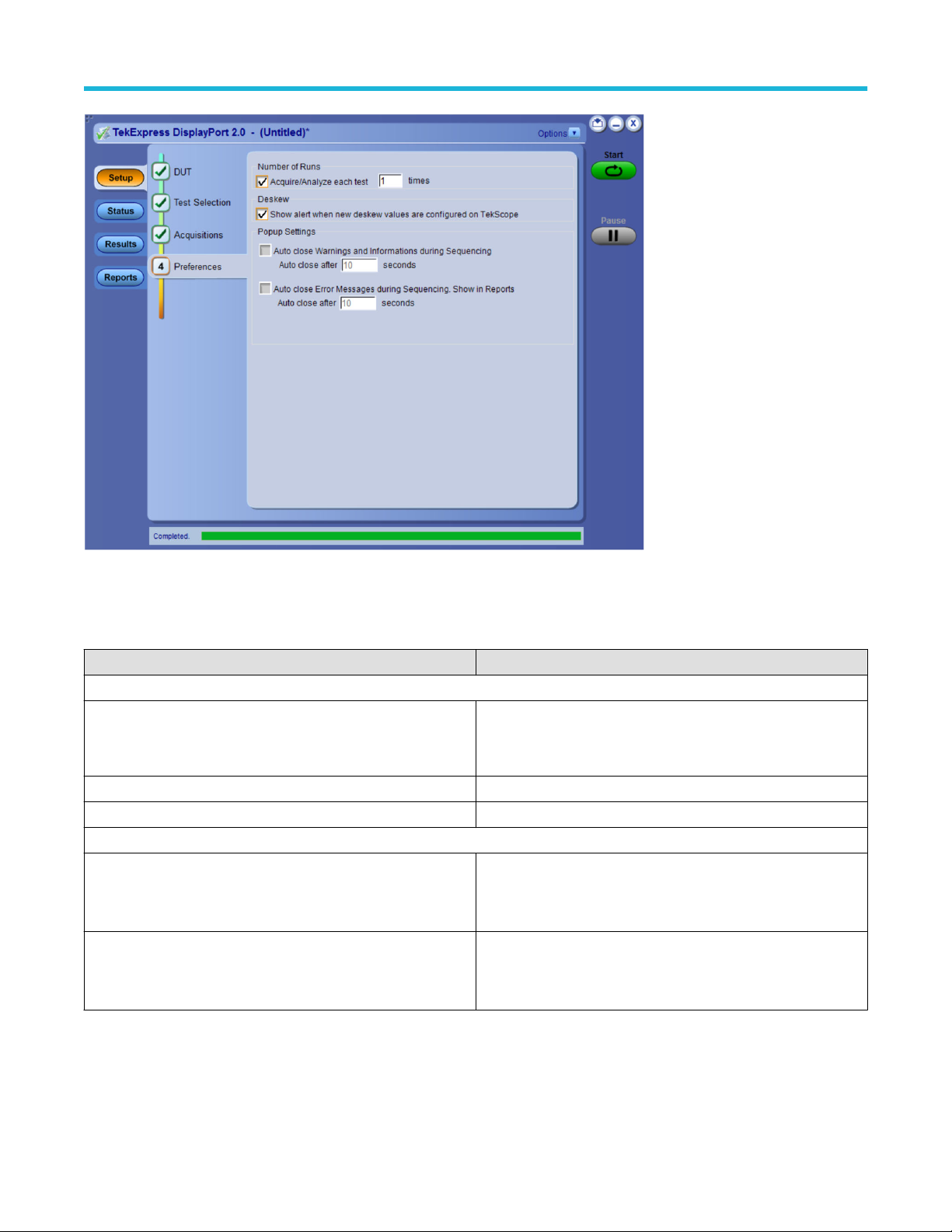
Preferences: Set the test run preferences
Use Preferences tab to set the application action on completion of a measurement. The Preferences tab has the feature to enable or
disable certain options related to the measurement execution.
TekExpress® DisplayPort 2.0 Automated Solution 42
Page 43
Setup panel: Configure the test setup
Figure 14: Preferences tab
Refer the below table for the options available in the Preferences tab:
Table 12: Preferences tab settings
Setting Description
Number of Runs
Acquire/Analyze each test <no> times (not applicable to Custom
Tests)
Deskew
Show alert when new deskew values are configured on TekScope
Popup Settings
Auto close Warnings and informations during Sequencing
Auto close after <no> seconds
Auto close Error Messages during Sequencing. Show in Reports
Auto close after <no> seconds
Select to repeat the test run by setting the number of times. By
default, check box is disabled. Upon enabling, the default value is
10.
Select to close the warnings and information window automatically
after the specified amount of time.
Specify the time in seconds using the edit box.
Select to close the error message window automatically after the
specified amount of time.
Specify the time in seconds using the edit box.
TekExpress® DisplayPort 2.0 Automated Solution 43
Page 44
Status panel: View the test execution status
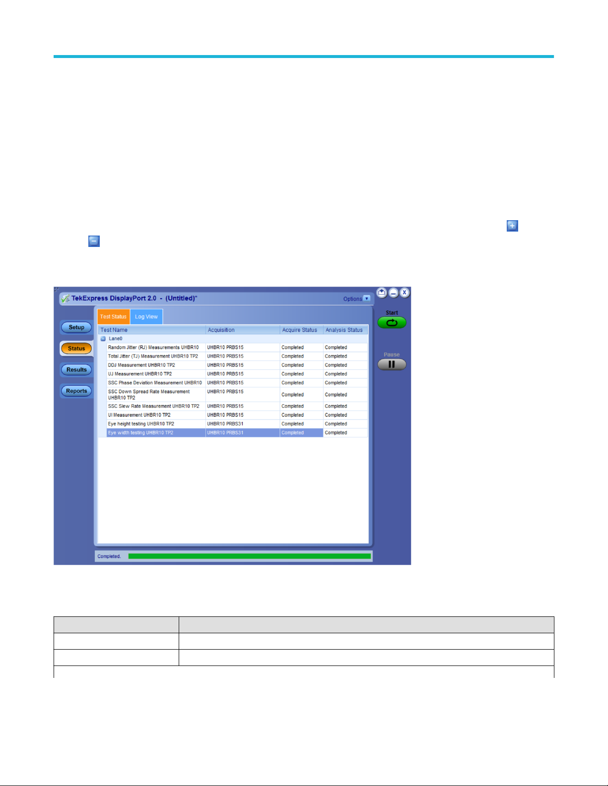
Status panel: View the test execution status
The Status panel contains the Test Status and Log View tabs, which provides status on the test acquisition and analysis (Test Status) and
listing of test tasks performed (Log View tab). The application opens the Test Status tab when you start to execute the test. Select the
Test Status or the Log View tab to view these items while the test execution is in progress.
View test execution status
The tests are grouped and displayed based on the Clock and Data lane. It displays the tests along with the acquisition type, acquire, and
analysis status of the tests. In pre-recorded mode, Acquire Status is not valid.
The Test Status tab presents a collapsible table with information about each test as it is running. Use the symbols to expand (
collapse ( ) the table rows.
) and
Figure 15: Test execution status view in Status panel
Table 13: Test execution status table headers
Table Header Description
Test Name Displays the measurement name.
Acquisition Describes the type of data being acquired.
Table continued…
TekExpress® DisplayPort 2.0 Automated Solution 44
Page 45

Status panel: View the test execution status
Table Header Description
Acquire Status Displays the progress state of the acquisition:
• To be started
• Started Acquisition
• Completed Acquisition
Analysis Status Displays the progress state of the analysis:
• To be started
• In Progress
• Completed
• Aborted
View test execution logs
The Test Status tab displays the detailed execution status of the tests. Also, displays each and every execution step in detail with its
timestamp information. The log details can be used to troubleshoot and resolve any issue/bug which is blocking the test execution process.
Figure 16: Log view in Status panel
Table 14: Status panel settings
Control Description
Message History Lists all the executed test operations and timestamp information.
Table continued…
TekExpress® DisplayPort 2.0 Automated Solution 45
Page 46

Control Description
Auto Scroll
Clear Log Clears all the messages from the log view.
Save
Enables automatic scrolling of the log view as information is added to the log during the test execution.
Saves the log file into a text file format. Use the standard Save File window to navigate to and specify
the folder and file name to save the log text.
Status panel: View the test execution status
TekExpress® DisplayPort 2.0 Automated Solution 46
Page 47

Results panel: View summary of test results
Results panel: View summary of test results
When a test execution is complete, the application automatically opens the Results panel to display a summary of test results.
In the Results table, each test result occupies a row. By default, results are displayed in summary format with the measurement details
collapsed and with the Pass/Fail column visible.
Figure 17: Results panel with measurement results
Click icon on each measurement in the row to expand and to display the minimum and maximum parameter values of the
measurement.
Filter the test results
Each column in the result table can be customized and displayed by enabling or disabling any column as per your requirement. You can
change the view in the following ways:
• To remove or restore the Pass/Fail column, select Preferences > Show Pass/Fail.
• To collapse all expanded tests, select Preferences > View Results Summary.
• To expand all the listed tests, select View Results Details from the Preferences menu in the upper right corner.
• To enable or disable the wordwrap feature, select Preferences > Enable Wordwrap.
• To view the results grouped by lane or test, select the corresponding item from the Preferences menu.
• To expand the width of a column, place the cursor over the vertical line that separates the column from the column to the right. When
the cursor changes to a double-ended arrow, hold down the mouse button and drag the column to the desired width.
• To clear all test results displayed, click Clear.
TekExpress® DisplayPort 2.0 Automated Solution 47
Page 48

Reports panel: Configure report generation settings
Reports panel: Configure report generation settings
Click Reports panel to configure the report generation settings and select the test result information to include in the report. You can use
the Reports panel to configure report generation settings, select test content to include in reports, generate the report, view the report,
browse for reports, name and save reports, and select report viewing options.
Select report generation options
This section describes the report generation settings you can configure in the Reports panel. Select report settings before running a test or
when creating and saving test setups. Report settings configured are included in saved test setups.
Figure 18: Reports panel
Report Update Mode Settings
Table 15: Report Update Mode Settings
Control Description
Generate new report Each time when you click Run and when the test execution
is complete, it will create a new report. The report can be in
either .mht, .pdf, or .csv file formats.
Append with previous run session Appends the latest test results to the end of the current test results
report. Each time when you click this option and run the tests, it will
run the previously failed tests and replace the failed test result with
the new pass test result in the same report.
Include header in appended reports Select to include header in appended reports.
Table continued…
TekExpress® DisplayPort 2.0 Automated Solution 48
Page 49

Reports panel: Configure report generation settings
Control Description
Replace current test in previous run session Replaces the previous test results with the latest test results.
Results from newly added tests are appended to the end of the
report.
In previous run, current session
In any run, any session Select to replace current test results in the report with the test
Report Creation Settings
Report name
Select to replace current test results in the report with the test
result(s) of previous run in the current session.
result(s) in the selected run session’s report. Click and select test
result of any other run session.
Displays the name and path of the <Application Name>
report. The default location is at \My Documents>\My
TekExpress\<Application Name>\Reports. The
report file in this folder gets overwritten each time you run a test
unless you specify a unique name or select to auto increment the
report name.
To change the report name or location, do one of the following:
Save as type
• In the Report Path field, type the current folder path and name.
• Double-click in the Report Path field and then make selections
from the popup keyboard and click Enter.
Be sure to include the entire folder path, the file name,
and the file extension. For example: C:\Documents
and Settings\your user name\My
Documents\My TekExpress\<Application
Name> \DUT001.mht.
Note: You cannot set the file location using the Browse
button.
Open an existing report
Click Browse, locate and select the report file and then click View
at the bottom of the panel.
Saves a report in the specified file type, selected from the dropdown list. The report is saved in .csv, .pdf, or .mht.
Note:
If you select a file type different from the default, be sure to
change the report file name extension in the Report Name
field to match.
Auto increment report name if duplicate
Create report automatically at the end of the run
Table continued…
TekExpress® DisplayPort 2.0 Automated Solution 49
Sets the application to automatically increment the name of the
report file if the application finds a file with the same name as the
one being generated. For example: DUT001, DUT002, DUT003.
This option is enabled by default.
Select to create the report with the settings configured, at the end of
run.
Page 50

Reports panel: Configure report generation settings
Control Description
Contents To Save Settings
Include pass/fail info in details table Select to include pass/fail information in the details table of the
report.
Include detailed results Select to include detailed results in the report.
Include plot images Select to include the plot images in the report.
Include setup configuration
Include complete application configuration Select to include the complete application configuration in the
Include user comments
Sets the application to include hardware and software information in
the summary box at the top of the report. Information includes: the
oscilloscope model and serial number, the oscilloscope firmware
version, and software versions for applications used in the
measurements.
report.
Select to include any comments about the test that you or another
user have added in the DUT tab of the Setup panel. Comments
appear in the Comments section, below the summary box at the
beginning of each report.
Include statics table
Include Informative Results Select to include results for informative tests.
Other settings in report panel
View report after generating
View Click to view the most current report.
Generate Report Generates a new report based on the current analysis results.
Save As Specify a name for the report.
Group Report By
Test Name Select to group the test results based on the test name in the report.
Test Result Select to group the test results based on the test result in the report.
Lane Name Select to group the test results based on the Lanes in the report
Data Rate Select to group the test results based on the Data Rate in the report
Images Select to group the test results based on the image in the report
Report Type
Compliance Select to include compliance results
All results Select to include all results.
Select to include test run statistics in the report. This is enabled
when you run any test for more than once. Set Acquire/Analyze
each test in the Preferences tab to more than one, to run any test
for multiple times.
Automatically opens the report in a Web browser when the test
execution is complete. This option is selected by default.
TekExpress® DisplayPort 2.0 Automated Solution 50
Page 51

View a generated report
Sample report and its contents
A report shows detailed results and plots, as set in the Reports panel.
Reports panel: Configure report generation settings
Figure 19: Report for DisplayPort2.0
Setup Information The summary box at the beginning of the report lists setup configuration information. This information
includes the oscilloscope model and serial number, optical module model and serial number, and software
version numbers of all associated applications.
Test Name Summary Table The test summary table lists all the tests which are executed with its result status.
Measurement The measurement table displays the measurement related details with its parameter value.
User comments If you had selected to include comments in the test report, any comments you added in the DUT tab are
shown at the top of the report.
Optimum CTLE Table The Optimum CTLE Table shows the details of the optimum CTLE for all TP3_EQ measurements.
TekExpress® DisplayPort 2.0 Automated Solution 51
Page 52

Saving and recalling test setup
Saving and recalling test setup
Test setup files overview
Saved test setup information (such as the selected oscilloscope, general parameters, acquisition parameters, measurement limits,
waveforms (if applicable), and other configuration settings) are saved under the setup name at X:\<Application Name>.
Use test setups to:
• Run a new session, acquire live waveforms, using a saved test configuration.
• Create a new test setup using an existing one.
• View all the information associated with a saved test, including the log file, the history of the test status as it executed, and the results
summary.
• Run a saved test using saved waveforms.
Save the configured test setup
You can save a test setup before or after running a test. You can create a test setup from already created test setup or using a default
test setup. When you save a setup, all the parameters, measurement limits, waveform files (if applicable), test selections, and other
configuration settings are saved under the setup name. When you select the default test setup, the parameters are set to the application’s
default value.
Select Options > Save Test Setup to save the opened setup.
Select Options > Save Test Setup As to save the setup with different name.
Load a saved test setup
To open (load) a saved test setup, do the following:
• Select Options > Open Test Setup.
• Select the setup from the list and click Open. Setup files are located at X:\<Application Name>.
Select a pre-run session from the loaded test setup
Complete the following steps to load a test setup from a pre-run session:
1. Select Options > Open Test Setup.
2. Select a setup from the list and then click Open. Setup files are located at X:\<Application Name>\.
3. Switch the mode to Pre-recorded waveform files in the DUT panel.
4. Select the required waveforms from the selected setup in the Acquisition tab and Run the required test.
TekExpress® DisplayPort 2.0 Automated Solution 52
Page 53

Save the test setup with a different name
To create a test setup with a different name, follow the steps:
1. Select Options > Open Test Setup.
2. Select a setup from the list and then click Open.
3. Click application setup and modify the parameters.
4. Click application reports and modify the report options.
5. Select Options > Save Test Setup As.
6. Enter the test setup name and click Save.
Saving and recalling test setup
TekExpress® DisplayPort 2.0 Automated Solution 53
Page 54
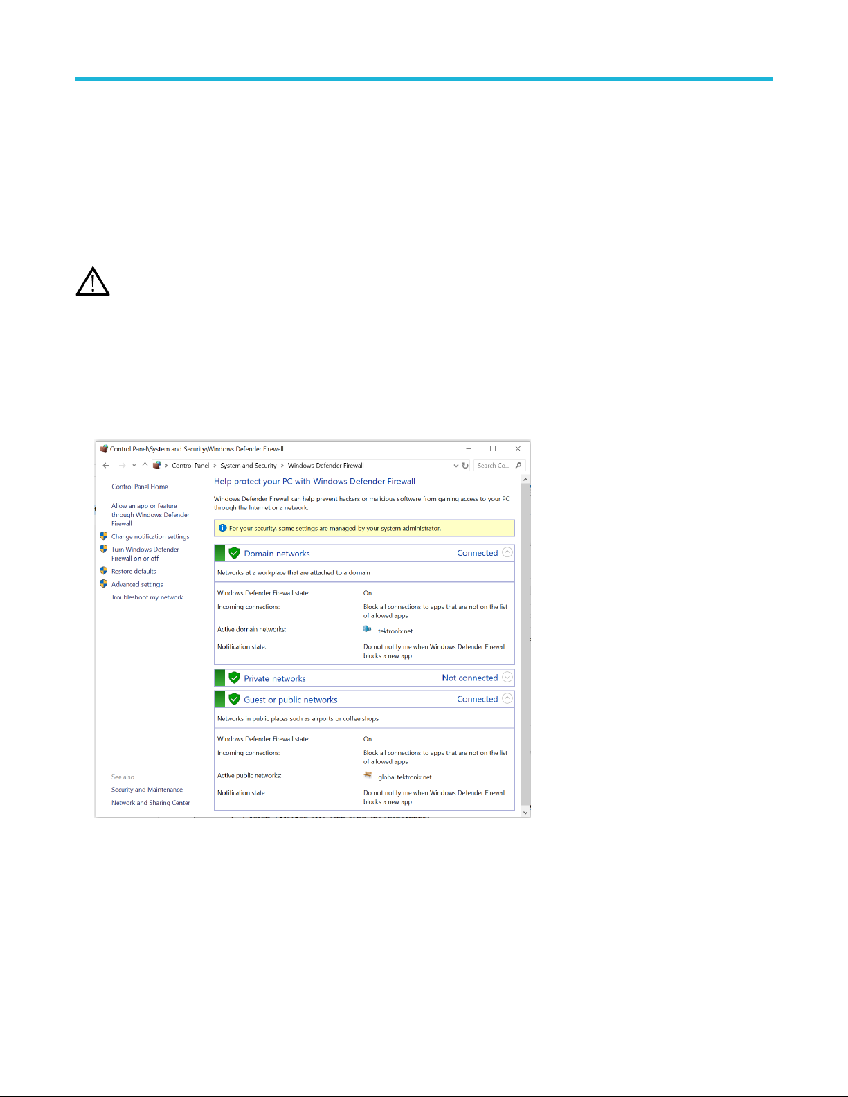
SCPI Commands
SCPI Commands
About SCPI command
You can use the Standard Commands for Programmable Instruments (SCPI) to communicate remotely with the TekExpress application.
Complete the TCPIP socket configuration and the TekVISA configuration in the oscilloscope or in the device where you are executing the
script.
Note: If you are using an external PC to execute the remote interface commands, then install TekVISA in the PC to make the
configurations.
Socket configuration for SCPI commands
This section describes the steps to configure the TCPIP socket configuration in your script execution device and the steps to configure the
TekVISA configuration in the oscilloscope to execute the SCPI commands.
TCPIP socket configuration
1. Click Start > Control Panel > System and Security > Windows Firewall > Advanced settings.
2. In Windows Firewall with Advanced Security menu, select Windows Firewall with Advanced Security on Local Computer >
Inbound Rules and click New Rule…
TekExpress® DisplayPort 2.0 Automated Solution 54
Page 55

3. In New Inbound Rule Wizard menu
a. Select Port and click Next.
SCPI Commands
b. Select TCP as rule apply, enter 5000 for Specific local ports and click Next.
TekExpress® DisplayPort 2.0 Automated Solution 55
Page 56

SCPI Commands
c. Select Allow the connection and click Next.
d. Select Domain, Private, Public checkbox and click Next.
TekExpress® DisplayPort 2.0 Automated Solution 56
Page 57

SCPI Commands
e. Enter Name, Description (optional), and click Finish.
4. Check whether the Rule name is displayed in Windows Firewall with Advanced Security menu > Inbound Rules.
TekExpress® DisplayPort 2.0 Automated Solution 57
Page 58

TekVISA configuration
1. Click Start > All Programs > TekVISA > OpenChoice Instrument Manager.
SCPI Commands
2. Click Search Criteria. In Search Criteria menu, click LAN to Turn-on. Select Socket from the drop-down list, enter the IP address of
the TekExpress device in Hostname and type Port as 5000. Click to configure the IP address with Port.
Enter the Hostname as 127.0.0.1 if the TekVISA and TekExpress application are in the same system, else enter the IP address of the
oscilloscope where the TekExpress application is running.
TekExpress® DisplayPort 2.0 Automated Solution 58
Page 59
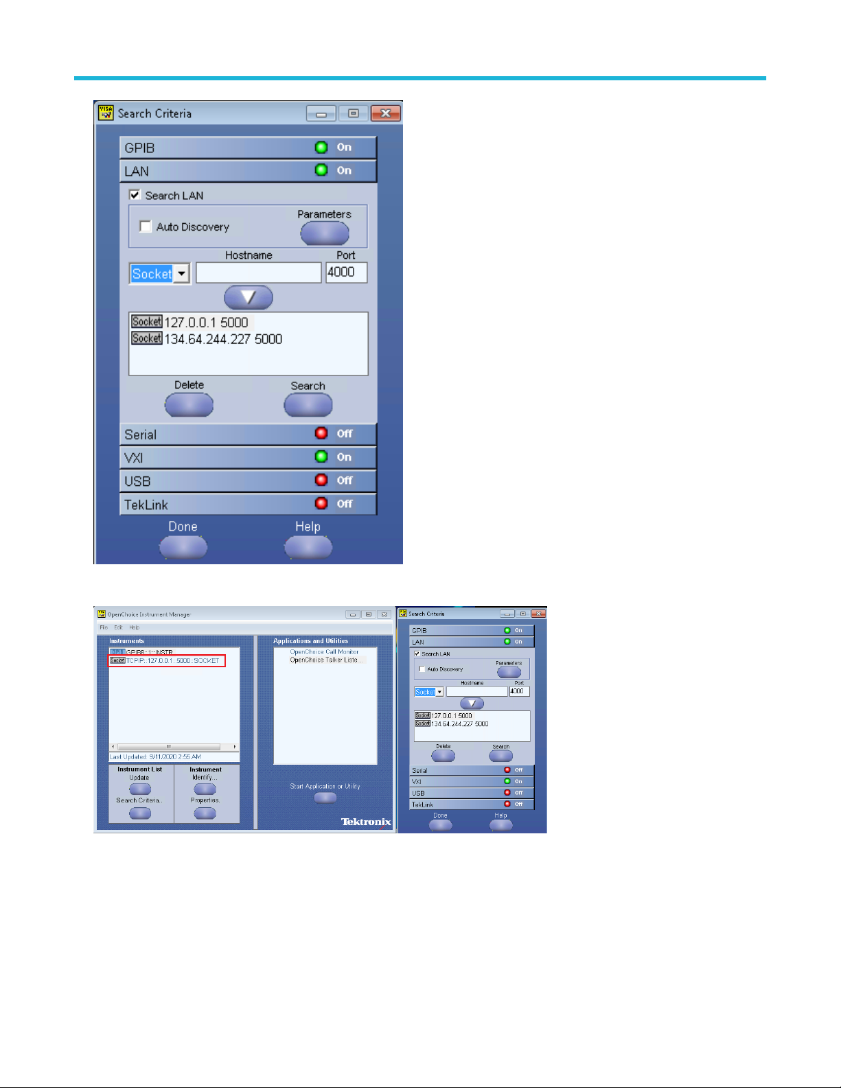
SCPI Commands
3. Click Search to setup the TCPIP connection with the host. Check whether the TCPIP host name is displayed in OpenChoice
Instrument Manager > Instruments.
4. Double-click OpenChoice Talker Listener and enter the Command *IDN? in command entry field and click Query. Check that the
Operation is successful and Talker Listener Readout displays the Command / Data.
TekExpress® DisplayPort 2.0 Automated Solution 59
Page 60

SCPI Commands
Set or query the device name of application
This command sets or queries the device name of the application.
Syntax
TEKEXP:SELECT DEVICE,"<DeviceName>" (Set)
TEKEXP:SELECT? DEVICE (Query)
Command arguments
Argument Name Argument Type
<DeviceName> <String>
Returns
<String>
Examples
TEKEXP:SELECT DEVICE,"<DUT001>" command sets the device name of the application to DUT001.
TEKEXP:SELECT? DEVICE command returns the selected device name of the application.
Set or query the DUTID of application
This command sets or queries the DUTID of the application.
Syntax
TEKEXP:VALUE DUTID,"<Value>" (Set)
TEKEXP:VALUE? DUTID (Query)
TekExpress® DisplayPort 2.0 Automated Solution 60
Page 61

Command arguments
Argument Name Argument Type
<Value> <String>
Returns
<String>
Examples
TEKEXP:VALUE DUTID,"DUT001" command sets the DUTID of the application to DUT001.
TEKEXP:VALUE? DUTID command returns the DUTID of the application.
Set or query the suite name of the application
This command sets or queries the suite name of the application.
Syntax
TEKEXP:SELECT SUITE,"<SuiteName>" (Set)
TEKEXP:SELECT? SUITE (Query)
SCPI Commands
Command arguments
Returns
<String>
Examples
TEKEXP:SELECT SUITE,"<SuiteName>" command sets the suite name of the application.
TEKEXP:SELECT? SUITE command returns the selected suite of the application.
Set or query the test name of the application
This command selects or deselects the specified test name of the application.
Syntax
TEKEXP:SELECT TEST,"<TestName>",<Value> (Set)
TEKEXP:SELECT TEST,"<ALL>" (Set)
TEKEXP:SELECT? TEST (Query)
TekExpress® DisplayPort 2.0 Automated Solution 61
Page 62

Command arguments
TestName Value
• Eye Diagram Testing
• Data Dependent Jitter (DDJ) Measurement
• Random Jitter (RJ) Measurement
• Total Jitter (TJ) Measurement
• Uncorrelated Jitter (UJ) Measurement
• Uncorrelated Deterministic Jitter (UDJ) Measurement
• Low Frequency Uncorrelated Deterministic Jitter
(LFUDJ)Measurement
• SSC Down Spread Rate Measurement
• SSC Phase Deviation Measurement
• SSC Slew Rate Measurement
• Unit Interval Measurement
{True | False} or {1 | 0}
It represents selected or unselected.
Where,
True or 1 - Selected
False or 0 - Unselected
Returns
SCPI Commands
{True | False} or {1 | 0}
Examples
TEKEXP:SELECT TEST,"<TestName>",1 command selects the specified test in the Test Panel.
TEKEXP:SELECT TEST,"<ALL>" command select all the tests in the Test Panel.
TEKEXP:SELECT? TEST command returns the list of selected tests.
Set or query the version name of the application
This command sets or queries the version name of the application.
Syntax
TEKEXP:SELECT VERSION,”<VersionName>” (Set)
TEKEXP:SELECT? VERSION (Query)
Command arguments
Argument Name Argument Type Valid Values
<VersionName> <String> It is the name of the version on the DUT panel of the application.
Returns
<String>
Examples
TEKEXP:SELECT VERSION,”<VersionName>” command sets the version name of application.
TEKEXP:SELECT? VERSION command returns the version name of application.
TekExpress® DisplayPort 2.0 Automated Solution 62
Page 63

Set or query the general parameter values
This command sets or queries the general parameter values of the application.
Syntax
TEKEXP:VALUE GENERAL,"<ParameterName>","<Value>" (Set)
TEKEXP:VALUE? GENERAL,"<ParameterName>" (Query)
Command arguments
Table 16: General command parameters
ParameterName Value
Connector
• Standard
• Type C
SCPI Commands
UHBR10
UHBR13.5
UHBR20
Voltage swing-800mV
SignalPreset_UHBR10
• Included
• Excluded
• Included
• Excluded
• Included
• Excluded
• Included
• Excluded
• P0
• P01
• P02
• P03
• P04
• P05
• P06
• P07
• P08
• P09
• P10
• P11
• P12
• P13
• P14
• P15
Table continued…
TekExpress® DisplayPort 2.0 Automated Solution 63
Page 64

ParameterName Value
SignalPreset_UHBR13.5
• P0
• P01
• P02
• P03
• P04
• P05
• P06
• P07
• P08
• P09
• P10
• P11
• P12
• P13
• P14
• P15
SCPI Commands
SignalPreset_UHBR20
SSC
• P0
• P01
• P02
• P03
• P04
• P05
• P06
• P07
• P08
• P09
• P10
• P11
• P12
• P13
• P14
• P15
• SSC Enable
• SSC Disable
• Both
Link Widths
Table continued…
TekExpress® DisplayPort 2.0 Automated Solution 64
• 1 Lane
• 2 Lanes
• 4 Lanes
Page 65

SCPI Commands
ParameterName Value
DUT control Manual
FilterfileDeEmbedPos C:\Users\Public\Tektronix\TekApplications\DisplayPort20\Filters\RF_
Cable_Deembed_POS.flt
FilterfileDeEmbedNeg C:\Users\Public\Tektronix\TekApplications\DisplayPort20\Filters\RF_
Cable_Deembed_Neg.flt
Signal Validation
Number of Runs 1 to 250
Timer Warning Info Message Popup
Timer Warning Info Message Popup Duration 1 to 60
Timer Error Message Popup
• Skip validation
• Skip test if validation fails
• Prompt if validation fails
• Validate pattern but use pattern as is
• TRUE
• FALSE
• TRUE
• FALSE
Timer Error Message Popup 1 to 60
Table 17: Report panel command parameters
<ParameterName> <Value>
Report Update Mode
Report Path
Save As Type
Auto increment report name if duplicate {True | False} or {1 | 0}
• New
• Append
• Replace
X:\<application name>\Reports\DUT001.mht
• Web Archive (*.mht;*.mhtml)
• PDF (*.pdf;)
• CSV (*.csv;)
It represents selected or unselected.
Where,
• True or 1 - Selected
• False or 0 - Unselected
Table continued…
TekExpress® DisplayPort 2.0 Automated Solution 65
Page 66

<ParameterName> <Value>
Create report at the end {True | False} or {1 | 0}
It represents selected or unselected.
Where,
• True or 1 - Selected
• False or 0 - Unselected
Include Pass/Fail Results Summary {True | False} or {1 | 0}
It represents selected or unselected.
Where,
• True or 1 - Selected
• False or 0 - Unselected
Include Detailed Results {True | False} or {1 | 0}
It represents selected or unselected.
Where,
• True or 1 - Selected
• False or 0 - Unselected
SCPI Commands
Include Plot Images {True | False} or {1 | 0}
It represents selected or unselected.
Where,
• True or 1 - Selected
• False or 0 - Unselected
Include Setup Configuration {True | False} or {1 | 0}
It represents selected or unselected.
Where,
• True or 1 - Selected
• False or 0 - Unselected
Include Complete Application Configuration {True | False} or {1 | 0}
It represents selected or unselected.
Where,
• True or 1 - Selected
• False or 0 - Unselected
Table continued…
TekExpress® DisplayPort 2.0 Automated Solution 66
Page 67

SCPI Commands
<ParameterName> <Value>
Include User Comments {True | False} or {1 | 0}
It represents selected or unselected.
Where,
• True or 1 - Selected
• False or 0 - Unselected
Returns
<NRf> or <String>
Examples
TEKEXP:VALUE GENERAL,"<ParameterName>","<Value>" command set the value for the specified general
parameter.
TEKEXP:VALUE? GENERAL,"<ParameterName>" command returns the value for the specified general parameter.
TekExpress® DisplayPort 2.0 Automated Solution 67
Page 68

SCPI Commands
Set or query the acquire parameter values
This command sets or queries the acquire parameter values of the application.
Syntax
TEKEXP:VALUE
ACQUIRE,”<TestName>",”<AcquireType>”,”<ParameterName>","<ParameterValue>" (Set)
TEKEXP:VALUE? ACQUIRE,”<TestName>",”<AcquireType>”,”<ParameterName>" (Query)
Command arguments
TestName AcquireType ParameterName ParameterValue
Eye Diagram Testing PRBS15 SignalPreset
Data Dependent Jitter (DDJ) Measurement
Random Jitter (RJ) Measurement
Total Jitter (TJ) Measurement
Uncorrelated Jitter (UJ) Measurement
Uncorrelated Deterministic Jitter (UDJ) Measurement
Low Frequency Uncorrelated Deterministic Jitter (LFUDJ)
Measurement
SSC Down Spread Rate Measurement
SSC Phase Deviation Measurement
SSC Slew Rate Measurement
Unit Interval Measurement
• P0
• P01
• P02
• P03
• P04
• P05
• P06
• P07
• P08
• P09
• P10
• P11
• P12
• P13
• P14
• P15
Returns
<Nrf>
Examples
TEKEXP:VALUE
ACQUIRE,”<TestName>",”<AcquireType>”,"<ParameterName>","<ParameterValue>" command sets
the value for the specified test and its acquire parameter.
TEKEXP:VALUE? ACQUIRE,”<TestName>",”<AcquireType>”,"<ParameterName>" command returns the
value for the specified test and its acquire parameter.
Set or query the analyze parameter values
This command sets or queries the analyze parameter values of the application.
TekExpress® DisplayPort 2.0 Automated Solution 68
Page 69

SCPI Commands
Syntax
TEKEXP:VALUE ANALYZE,”<TestName>","<ParameterName>","<ParameterValue>" (Set)
TEKEXP:VALUE? ANALYZE,”<TestName>","<ParameterName>" (Query)
Command arguments
TestName ParameterName ParameterValue
Eye Diagram Testing Cable filter file File Path
Returns
<Nrf>
Examples
TEKEXP:VALUE ANALYZE,”<TestName>","<ParameterName>","<ParameterValue>" command set the
value for the specified test and its analyze parameter.
TEKEXP:VALUE? ANALYZE,”<TestName>","<ParameterName>" command returns the value for the specified test
and its analyze parameter.
Query the available devices in the DUT panel of the application
This command queries the list of available devices on the DUT panel as comma separated values.
Syntax
TEKEXP:LIST? DEVICE (Query)
Command arguments
Device Device Type and value Description
<Device>
<String>
It is the name of the device on the DUT panel of the application.
Returns
<String>
Examples
TEKEXP:LIST? DEVICE command returns the list of available devices.
Query the available suites for the selected device
This command queries the list of available suites for the selected device as comma separated values.
Syntax
TEKEXP:LIST? SUITE (Query)
TekExpress® DisplayPort 2.0 Automated Solution 69
Page 70

Returns
<String>
Examples
TEKEXP:LIST? SUITE command returns the list of available suites for the selected device.
Query the list of available tests of the application
This command queries the list of available tests of the application for the selected device as comma separated values.
Syntax
TEKEXP:LIST? TEST (Query)
Command arguments
NA
TestName String
Eye height testing Eye height testing UHBR10 TP2
Eye height testing UHBR10 TP3
Eye height testing UHBR13.5 TP2
Eye height testing UHBR13.5 TP3
Eye height testing UHBR20 TP2
Eye height testing UHBR20 TP3
Eye width testing Eye width testing UHBR10 TP2
Eye width testing UHBR10 TP3
Eye width testing UHBR13.5 TP2
Eye width testing UHBR13.5 TP3
Eye width testing UHBR20 TP2
Eye width testing UHBR20 TP3
Data Dependent Jitter (DDJ) Measurement Data Dependent Jitter (DDJ) Measurement UHBR10 TP2
Data Dependent Jitter (DDJ) Measurement UHBR10 TP3
Data Dependent Jitter (DDJ) Measurement UHBR13.5 TP2
Data Dependent Jitter (DDJ) Measurement UHBR13.5 TP3
Data Dependent Jitter (DDJ) Measurement UHBR20 TP2
Data Dependent Jitter (DDJ) Measurement UHBR20 TP3
Random Jitter (RJ) Measurement Random Jitter (RJ) Measurement UHBR10 TP2
Random Jitter (RJ) Measurement UHBR10 TP3
Random Jitter (RJ) Measurement UHBR13.5 TP2
Random Jitter (RJ) Measurement UHBR13.5 TP3
Random Jitter (RJ) Measurement UHBR20 TP2
Random Jitter (RJ) Measurement UHBR20 TP3
Table continued…
SCPI Commands
TekExpress® DisplayPort 2.0 Automated Solution 70
Page 71

TestName String
Total Jitter (TJ) Measurement Total Jitter (TJ) Measurement UHBR10 TP2
Total Jitter (TJ) Measurement UHBR10 TP3
Total Jitter (TJ) Measurement UHBR13.5 TP2
Total Jitter (TJ) Measurement UHBR13.5 TP3
Total Jitter (TJ) Measurement UHBR20 TP2
Total Jitter (TJ) Measurement UHBR20 TP3
Uncorrelated Jitter (UJ) Measurement Uncorrelated Jitter (UJ) Measurement UHBR10 TP2
Uncorrelated Jitter (UJ) Measurement UHBR10 TP3
Uncorrelated Jitter (UJ) Measurement UHBR13.5 TP2
Uncorrelated Jitter (UJ) Measurement UHBR13.5 TP3
Uncorrelated Jitter (UJ) Measurement UHBR20 TP2
Uncorrelated Jitter (UJ) Measurement UHBR20 TP3
Uncorrelated Deterministic Jitter (UDJ)
Measurement
Low Frequency Uncorrelated Deterministic
Jitter (LFUDJ)Measurement
SSC Down Spread Rate Measurement SSC Down Spread Rate Measurement UHBR10 TP2
SSC Phase Deviation Measurement SSC Phase Deviation Measurement UHBR10 TP2
SSC Slew Rate Measurement SSC Slew Rate Measurement UHBR10 TP2
Unit Interval Measurement Unit Interval Measurement UHBR10 TP2
Uncorrelated Deterministic Jitter (UDJ) Measurement UHBR10 TP2
Uncorrelated Deterministic Jitter (UDJ) Measurement UHBR10 TP3
Uncorrelated Deterministic Jitter (UDJ) Measurement UHBR13.5 TP2
Uncorrelated Deterministic Jitter (UDJ) Measurement UHBR13.5 TP3
Uncorrelated Deterministic Jitter (UDJ) Measurement UHBR20 TP2
Uncorrelated Deterministic Jitter (UDJ) Measurement UHBR20 TP3
Low Frequency Uncorrelated Deterministic Jitter (LFUDJ)Measurement UHBR10 TP2
Low Frequency Uncorrelated Deterministic Jitter (LFUDJ)Measurement UHBR13.5 TP2
Low Frequency Uncorrelated Deterministic Jitter (LFUDJ)Measurement UHBR20 TP2
SSC Down Spread Rate Measurement UHBR13.5 TP2
SSC Down Spread Rate Measurement UHBR20 TP2
SSC Phase Deviation Measurement UHBR13.5 TP2
SSC Phase Deviation Measurement UHBR20 TP2
SSC Slew Rate Measurement UHBR13.5 TP2
SSC Slew Rate Measurement UHBR20 TP2
Unit Interval Measurement UHBR13.5 TP2
Unit Interval Measurement UHBR20 TP2
SCPI Commands
Returns
<String>
TekExpress® DisplayPort 2.0 Automated Solution 71
Page 72

SCPI Commands
Examples
TEKEXP:LIST? TEST command returns the list of available tests for the selected device.
Query the available version names of the application
This command queries the list of available version names of the application for the selected device as comma separated values.
Syntax
TEKEXP:LIST? VERSION (Query)
Returns
<String>
Examples
TEKEXP:LIST? VERSION command returns the list of version names for the selected device.
Query the list of available instruments based on the specified instrument type
This command queries the list of available instruments based on the specified instrument type.
Syntax
TEKEXP:LIST? INSTRUMENT,"<InstrumentType>" (Query)
Command argument
Argument Name Argument value
<InstrumentType> <String>
Returns
<String>
Examples
TEKEXP:LIST? INSTRUMENT,"Real Time Scope" command returns the list of available instruments based on the real
time scope type.
Set or query the IP address of the instrument based on the specified instrument type
This command sets or queries the IP address of the instrument based on the specified instrument type.
Syntax
TEKEXP:INSTRUMENT? "<InstrumentType>" (Query)
TEKEXP:INSTRUMENT, "<InstrumentType>","<Value>" (Set)
Command argument
Argument Name Argument Type
<InstrumentType> <String>
Table continued…
TekExpress® DisplayPort 2.0 Automated Solution 72
Page 73

SCPI Commands
Argument Name Argument Type
<Value> <String>
TCPIP::XXX.XX.XXX.XXX::INSTR
Returns
<String>
Examples
TEKEXP:INSTRUMENT? "<InstrumentType>" command returns the IP address of the oscilloscope.
TEKEXP:INSTRUMENT, "<InstrumentType>","<value>" command sets the oscilloscope to the specified IP address.
Query the information of the generated report file
This command queries the information of the generated report file in the format "<FileSize>","<FileName>".
Pre‐requisite
A session should be run earlier and the report should be generated to get the information of the report.
Syntax
TEKEXP:INFO? REPORT (Query)
Returns
<FileSize>:: <String>
<FileName>:: <String>
Examples
TEKEXP:INFO? REPORT command returns the information of the generated report in the format ("1215”,"DUT001.mht”).
Query the information of the generated waveform files
This command queries the information of the generated waveform files in the format.
<File1Size,"File1Name”>.
If there are more than one waveform, the waveform file names are displayed with the comma separated values in the format
<File1Size,"File1Name">,<File2Size,"File2Name">.
Syntax
TEKEXP:INFO? WFM (Query)
Returns
<FileSize>:: <String>
<FileName>:: <String>
Examples
TEKEXP:INFO? WFM command returns the information of the generated waveform in the format (20000858,"X:\<Application
Name>\Untitled Session\DUT001\20200916_041609\Iter1_Short Record‐length for SCOPE Period_NoSSC_DIFF.wfm”).
TekExpress® DisplayPort 2.0 Automated Solution 73
Page 74

Query the information of the generated image files
This command queries the information of the generated image files in the format.
<File1Size,"File1Name”>.
If there are more than one image, the image file names are displayed with the comma separated values in the format
<File1Size,"File1Name">,<File2Size,"File2Name">.
Syntax
TEKEXP:INFO? IMAGE (Query)
Returns
<FileSize>:: <String>
<FileName>:: <String>
Examples
TEKEXP:INFO? IMAGE command returns the information of the generated image
in the format (109058, "X:\<Application Name>\Untitled Session\DUT001\20200916_041609\Iter1_Short
Record‐length for SCOPE Period_NoSSC_DIFF.png";22794,"X:\<Application Name>\UntitledSession\DUT001\20
200916_041609\ScopePeriodPlot_Iteration1WithCursor.png").
SCPI Commands
Query the active TekExpress application name
This command queries the active TekExpress application name running on the oscilloscope.
Syntax
TEKEXP:*IDN? (Query)
Returns
<String>
Examples
TEKEXP:*IDN? command returns the active TekExpress application name running on the oscilloscope.
Sets or query the acquire mode status
This command sets or queries the acquire mode status.
Syntax
TEKEXP:ACQUIRE_MODE <Mode> (Set)
TEKEXP:ACQUIRE_MODE? (Query)
Command arguments
Argument Name Argument value
<Mode>
• LIVE
• PRE‐RECORDED
TekExpress® DisplayPort 2.0 Automated Solution 74
Page 75

Returns
LIVE | PRE‐RECORDED
Examples
TEKEXP:ACQUIRE_MODE LIVE command sets the acquire mode to the Live mode.
TEKEXP:ACQUIRE_MODE? command returns the current acquire mode.
Set or query the execution mode status
This command sets or queries the execution mode status.
Syntax
TEKEXP:MODE <Mode> (Set)
TEKEXP:MODE? (Query)
Command arguments
Argument Name Argument value
<Mode>
• COMPLIANCE
• USER‐DEFINED
SCPI Commands
Returns
COMPLIANCE | USER‐DEFINED
Examples
TEKEXP:MODE COMPLIANCE command sets the execution mode to the compliance mode.
TEKEXP:MODE? command returns the current execution mode.
Generate the report for the current session
This command generates the report for the current session.
Syntax
TEKEXP:REPORT GENERATE(Set)
Arguments
N/A
Examples
TEKEXP:REPORT GENERATE command generates the report for the current session.
Query the value of specified report header field in the report
This command queries the value of specified report header field in the report.
Syntax
TEKEXP:REPORT? ”<Device Field>” (Query)
TekExpress® DisplayPort 2.0 Automated Solution 75
Page 76

Command arguments
Argument Name Argument Type
<Device Field>
Device field is the header name of each field in the setup
information section of the report.
<String>
Returns
<String>
Examples
TEKEXP:REPORT? "DUT ID" command returns the value of DUT ID field in the report.
SCPI Commands
Query the value of specified result detail available in report summary/details table
This command queries the value of specified result detail available in report summary/details table.
Syntax
TEKEXP:RESULT? "<TestName>" (Query)
TEKEXP:RESULT? "<TestName>","<ColumnName>" (Query)
TEKEXP:RESULT? "<TestName>","<ColumnName>",<RowNumber> (Query)
Command arguments
Argument Name Argument Type
<TestName>
It is the test name of which the details are required in the report.
<ColumnName>
It is the column header name of which the details are required in the
report.
<RowNumber>
It is the row number of which the details are required in the report.
<String>
<String>
<String>
Returns
<String>
Examples
TEKEXP:RESULT? "<TestName>" will return the pass fail status of test.
TekExpress® DisplayPort 2.0 Automated Solution 76
Page 77

SCPI Commands
TEKEXP:RESULT? "<TestName>","<ColumnName>" will return all the row values of specific column for the test with
comma separated values.
TEKEXP:RESULT? "<TestName>","<ColumnName>",<RowNumber> will return the column value of specified row
number.
Restore the setup to default settings
This command restores the setup to default settings.
Syntax
TEKEXP:SETUP Default (Set)
Arguments
N/A
Examples
TEKEXP:SETUP Default command restores the setup to default settings.
Save the settings to a specified session
This command saves the settings to a specified session.
Syntax
TEKEXP:SETUP Save,"<SessionName>"
Command arguments
Argument Name Argument value
<SessionName> <String>
Examples
TEKEXP:SETUP Save,"<SessionName>" command saves the settings to a specified session.
Open the setup from a specified session
This command opens the setup from a specified session.
Syntax
TEKEXP:SETUP Open,"<SessionName>" (Set)
Command arguments
Argument Name Argument value
<SessionName> <String>
Examples
TEKEXP:SETUP Open,"<SessionName>" command opens the setup from a specified session.
TekExpress® DisplayPort 2.0 Automated Solution 77
Page 78

SCPI Commands
Query the current setup file name
This command queries the current setup file name.
Syntax
TEKEXP:SETUP? CURRENT (Query)
Returns
<String>
Examples
TEKEXP:SETUP? CURRENT command returns the current setup file name.
Run/stop/pause/resume the selected measurements execution in the application
This command run/stop/pause/resume the selected measurements execution in the application.
Syntax
TEKEXP:STATE <operation mode> (Set)
Command arguments
Argument Name Argument value
<operation mode>
• RUN
• STOP
• PAUSE
• RESUME
Returns
RUN | STOP | PAUSE | RESUME
Examples
TEKEXP:STATE RUN command runs the execution for the selected measurements.
Query the current measurement execution status
This command queries the current measurement execution status.
Syntax
TEKEXP:STATE? (Query)
Returns
RUNNING | PAUSED | WAIT | ERROR | READY
Examples
TEKEXP:STATE? command returns the current measurement execution status.
TekExpress® DisplayPort 2.0 Automated Solution 78
Page 79

Query whether the current setup is saved or not saved
This command queries whether the current setup is saved or not saved.
Syntax
TEKEXP:STATE? SETUP (Query)
Returns
Saved or Not‐Saved
Examples
TEKEXP:STATE? SETUP command returns whether the current setup is saved or not saved.
Query the status of the previous command execution
This command queries whether the previous command execution is completed successfully.
Syntax
TEKEXP:*OPC? (Query)
Returns
SCPI Commands
{0 | 1} or {True | False}
1 or True indicates that command execution is successful.
0 or False indicates that command execution is failed.
Examples
TEKEXP:*OPC? command returns whether the previous command operation is completed successfully.
Query the last error occurred
This command queries the last error occurred.
Syntax
TEKEXP:LASTERROR? (Query)
Returns
<String>
Examples
TEKEXP:LASTERROR? command returns the last error occurred.
Set or query the popup details
This command sets or queries the popup details.
Syntax
TEKEXP:POPUP? (Query)
TEKEXP:POPUP "<PopupResponse>" (Set)
TekExpress® DisplayPort 2.0 Automated Solution 79
Page 80

SCPI Commands
Command arguments
Argument Name Argument value
<PopupResponse>
• Yes
• No
Returns
The pop‐up details return in the following format:
"<Tittle>","<message>","<response1>,<response2>".
Where,
<Tittle> :: <String>
<message> :: <String>
<response1>,<response2> :: <String>
Examples
TEKEXP:POPUP? command returns the popup details in following format ": "Do you really want to exit TekExpress?";Responses: "Yes,
No".
TEKEXP:POPUP "Yes" command sets the popup response to Yes.
Set or query the View report after generating option status
This command sets or queries the enable/disable status of the View report after generating function.
Syntax
TEKEXP:VALUE? GENERAL,"View Report After Generating" (Query)
TEKEXP:VALUE GENERAL,"View Report After Generating",<value> (Set)
Arguments
Argument Name Argument value
<Value> {True | False} or {1 | 0}
It represents enabled or disabled.
Where,
• True or 1 - enabled
• False or 0 - disabled
Returns
{True | False} or {0 | 1}
Examples
TEKEXP:VALUE? GENERAL,"View Report After Generating" command returns the enable or disable status of
view report after generating option.
TekExpress® DisplayPort 2.0 Automated Solution 80
Page 81

SCPI Commands
TEKEXP:VALUE GENERAL,"View Report After Generating",<value> command enable or disable the view
report after generating option.
Set or query the enable/disable status of Verbose function
This command sets or queries the enable/disable status of Verbose function.
Syntax
TEKEXP:VALUE VERBOSE,"<Value>" (Set)
TEKEXP:VALUE? VERBOSE (Query)
Arguments
Argument Name Argument value
<Value> {True | False} or {1 | 0}
It represents enabled or disabled.
Where,
• True or 1 - enabled
• False or 0 - disabled
Returns
{True | False} or {0 | 1}
Examples
TEKEXP:VALUE VERBOSE,"<Value>" command enable or disable the Verbose function.
TEKEXP:VALUE? VERBOSE command returns the enable or disable status of Verbose function.
Set or query the waveform file recalled for the specified test name and acquire type
This command set or queries the waveform file recalled for the specified test name and acquire type.
If there are more than one waveform, the waveform file names are displayed with the symbol "$" separated values in the format
<WaveformFileName1$ WaveformFileName2>.
Syntax
TEKEXP:VALUE WFMFILE,<TestName>,<AcquireType>,<WaveformFileName> (Set)
TEKEXP:VALUE? WFMFILE,<TestName>,<AquireType> (Query)
Returns
<String>
Examples
TEKEXP:VALUE WFMFILE,<TestName>,<AquireType>,<WaveformFileName> command recalls the sepcified
waveform file for the specified testname and acquire type.
TekExpress® DisplayPort 2.0 Automated Solution 81
Page 82

SCPI Commands
TEKEXP:VALUE? WFMFILE,<TestName>,<AquireType> command returns the waveform file name recalled for the
specified testname and acquire type.
Sets or query the limit values in the limits editor window
This command sets or queries the limit values in the limits editor window.
Syntax
TEKEXP:VALUE LIMIT,<TestName>,<LimitHeader>,<Value1>,<CompareString>,<Value2>(Set)
TEKEXP:VALUE? LIMIT,<TestName>,<LimitHeader> (Query)
Returns
<String> or <NRf>
Examples
TEKEXP:VALUE LIMIT,<TestName>,<LimitHeader>,<Value1>,<CompareString>,<Value2> command
sets the limits value for the specified testname and limit header.
TEKEXP:VALUE? LIMIT,<TestName>,<LimitHeader> command returns the limits value for the specified testname and
limit header.
Exit or close the application
The command exits or close the application
Syntax
TEKEXP:EXIT(Set)
Examples
TEKEXP:EXIT command close the application.
TekExpress® DisplayPort 2.0 Automated Solution 82
Page 83

Example
import socket
import time
#Create Socket
skt= socket.socket(socket.AF_INET,socket.SOCK_STREAM)
skt.connect(("localhost",5000))
#Measurement for execution
measurement = "Random Jitter (RJ) Measurements UHBR10 TP2"
#Setting the Mode to LIVE
skt.sendall("TEKEXP:ACQUIRE_MODE LIVE\n")
#setting the device
skt.sendall("TEKEXP:SELECT DEVICE,\"DisplayPort\"\n")
time.sleep (2)
skt.sendall("TEKEXP:SELECT? DEVICE\n")
SCPI Commands
time.sleep (2)
status=str(skt.recv(1024))
print "The selected device is : "+status
# Select the Suite
skt.sendall("TEKEXP:SELECT SUITE,\"Transmitter\"\n")
skt.sendall("TEKEXP:SELECT? SUITE\n")
time.sleep (5)
status=str(skt.recv(1024))
print "The selected Suite is : "+status
#GENERAL Parameters SCPI Commands
print "Started setting the GENERAL parameters"
#Set DUT ID
dutid = "DemoDUTID"
skt.sendall("TEKEXP:VALUE DUTID,"+dutid+"\n")
time.sleep(2)
skt.sendall("TEKEXP:VALUE? DUTID\n")
time.sleep (5)
status=str(skt.recv(1024))
print "After setting the DUT Id :"+status
#Exclude UHBR13.5 and UHBR20
TekExpress® DisplayPort 2.0 Automated Solution 83
Page 84

skt.sendall("TEKEXP:VALUE GENERAL,UHBR13.5,\"Excluded\"\n")
time.sleep (2)
skt.sendall("TEKEXP:VALUE GENERAL,UHBR20,\"Excluded\"\n")
time.sleep (2)
skt.sendall('TEKEXP:SELECT GENERAL,SignalPreset_UHBR10,P0_\n')
time.sleep(5)
skt.sendall('TEKEXP:SELECT GENERAL,SSC,SSC_Enable\n')
time.sleep(5)
skt.sendall("TEKEXP:VALUE? GENERAL,UHBR10\n")
time.sleep (5)
#Select singlepreset
print "The selected Measurement is : "+measurement
status=str(skt.recv(1024))
print "Unselecting the UHBR135 and UHBR20 datarates :"+status
SCPI Commands
# Deselect All
skt.sendall('TEKEXP:SELECT TEST,ALL,FALSE'+'\n')
# Select Measurement
print "Select Measurement : "+measurement
skt.sendall('TEKEXP:SELECT TEST,'+'Random Jitter (RJ) Measurements UHBR10 TP2,'+'TRUE'+'\n')
time.sleep(5)
print "The selected Measurement is : "+measurement
# For de-selecting measurement use - skt.sendall("TEKEXP:SELECT TEST,"+""measurement""+"FALSE\n")
#Start running the selected Test
print "Starting Run"
skt.sendall("TEKEXP:STATE RUN\n")
print "Clicked start button."
time.sleep(5)
skt.sendall("TEKEXP:POPUP \"OK\"\n")
time.sleep(10)
skt.sendall("TEKEXP:STATE?\n")
time.sleep(5)
status = str(skt.recv(1024))
print "Hi"
status=status.strip()
TekExpress® DisplayPort 2.0 Automated Solution 84
Page 85

while (status == "RUNNING" or status == "ERROR" or status=="WAIT"):
print "Running..."
skt.sendall("TEKEXP:STATE?\n")
time.sleep(2)
status = str(skt.recv(1024))
status = status.strip()
if status == "ERROR\n" or status=="WAIT\n":
skt.sendall("TEKEXP:POPUP?\n")
status = str(skt.recv(1024))
print status
popupResponse = raw_input("Enter popup response:")
skt.sendall("TEKEXP:POPUP "+"\""+popupResponse+"\""+"\n")
status = str(skt.recv(1024))
print "Measurement execution completed."
SCPI Commands
#Transfer the reports
print "Getting the info of Report file..."
skt.sendall("TEKEXP:INFO? REPORT\n")
status = str(skt.recv(1024))
print "ReportFile Info: "+status
fileInfo= status.split(',')
fileLength = long(fileInfo[0])
destinationPath = "C:\\"
print "Exporting report file to client location "+destinationPath+" ..."
skt.sendall("TEKEXP:EXPORT REPORT\n")
while(len(status) < fileLength):
received = skt.recv(fileLength)
status = status + received
fileName = fileInfo[1].strip()
fileName = fileName.strip('\"')
time.sleep(15)
f= open(destinationPath+fileName,'wb')
f.write(status)
f.close()
print "Export completed for "+fileName
TekExpress® DisplayPort 2.0 Automated Solution 85
Page 86

#Saving Session
sessionName = 'PI_Session1'
skt.sendall("TEKEXP:SETUP SAVE,"+sessionName+"\n")
time.sleep (3)
print "Querying the result of ..."
skt.sendall("TEKEXP:RESULT? \"Test 3.1_Eye diagram testing\"\n")
time.sleep(5)
status = str(skt.recv(1024))
status=status.strip()
print "The result of"+measurement+"is"+status
skt.close()
SCPI Commands
TekExpress® DisplayPort 2.0 Automated Solution 86
Page 87

References
References
Application directories
You can find the application files at C:\Program Files\Tektronix\<Application Name>. The application directory and associated files are
organized as follows:
The following table lists the default directory names and their usage:
Table 18: Application directories and usage
Directory names Usage
Bin Contains application libraries
Compliance Suites Contains test suite specific files
Examples Contains various support files
ICP Contains instrument and application specific interface libraries
Images Contains images of the application
Lib Contains utility files specific to the application
Licenses Contains all the license files
Report Generator Contains style sheets for report generation
Tools Contains instrument and application specific files
TekExpress® DisplayPort 2.0 Automated Solution 87
Page 88

File name extensions
The TekExpress <Application Name> software uses the following file name extensions:
Table 19: File name extension
File name extension Description
*.TekX Application session files (the extensions may not be displayed)
*.py Python sequence file.
*.xml
Test-specific configuration information (encrypted) files.
Application log files
References
*.csv
*.mht
*.pdf
*.xslt Style sheet used to generate reports
*.png Captured images
Test result reports
Plot data
Test result reports (default)
Test reports can also be saved in HTML format
Test result reports
Application help document
View test-related files
Files related to tests are stored in My Documents\<Application Name>\Untitled session folder. Each test setup in this folder has both a test
setup file and a test setup folder, both with the test setup name. The test setup file is preceded by the TekExpress icon.
Inside the test setup folder is another folder named for the DUT ID used in the test sessions. The default is DUT001.
Inside the DUT001 folder are the session folders and files. Each session also has a folder and file pair, both named for the test session
using the naming convention (date)_(time). Each session file is stored outside its matching session folder:
Each session folder contains image files of any plots generated from running the test session. If you selected to save all waveforms or ran
tests using prerecorded waveform files, these are included here.
TekExpress® DisplayPort 2.0 Automated Solution 88
Page 89

References
The first time you run a new, unsaved session, the session files are stored in the Untitled Session folder located at X: \<Application Name>.
When you name and save the session, the files are placed in a folder with the name that you specify. A copy of the test files stay in the
Untitled Session folder until you run a new test or until you close the application.
Deskew channels
If skew is present between positive and negative channels, then the channels need to be deskewed before being used for waveform
measurements. TekExpress DisplayPort 2.0 solution provides support for channel deskew using the following method:
1. Determine what the skew is for each channel.
2. From the TekScope menu, click Vertical and select Deskew.
3. In the Deskew/Attenuation window, click the channel (1 – 4) button for the first channel to be deskewed.
4. Click in the Ch(x) Deskew Time entry field and enter the skew. The skew can be +ve or –ve.
5. Click the channel button for the next channel and repeat step 4, above.
6. After entering the skew for all the channels that require it, from the Options menu in TekExpress DisplayPort 2.0, select Deskew.
7. In the Deskew dialog box, select the desired level:
• Less than 100 mV signal amplitude: Select this if the signal amplitude is such that the oscilloscope’s vertical setting is less than
100 mV/division.
• 100 mV or greater signal amplitude: Select this if the signal amplitude is such that the oscilloscope’s vertical setting is greater than
100 mV/division.
8. Click Read Deskew/Attn.
9. When finished, click Close.
Each input channel has its own deskew settings. Deskew compensates individual channels for probes or cables of different lengths. The
instrument applies the delay values after each completed acquisition. The deskew values are saved as part of the instrument setup. The
deskew values for the selected channel are retained until you change the probe, you restore a saved setup, or you recall the factory setup.
See Also
Pre-Run checklist
TekExpress® DisplayPort 2.0 Automated Solution 89
Page 90

Appendix-A
Following are the compliance parameters for all DisplayPort 2.0 measurements
Table 20: Compliance Parameters list for all DisplayPort 2.0 measurements
Test Name Data Rate Preset Voltage Swing SSC Test Point
Eye Diagram Testing
Data Dependent
Jitter (DDJ)
Measurement
Random Jitter (RJ)
Measurement
Total Jitter (TJ)
Measurement
Uncorrelated Jitter
(UJ) Measurement
Uncorrelated
Deterministic Jitter
(UDJ) Measurement
• UHBR10
• UHBR13.5
• UHBR20
• P0
• P01
• P02
• P03
• P04
• P05
• P06
• P07
• P08
• P09
• P10
• P11
• P12
• P13
• P14
• P15
800 mV
• SSC Enabled
• SSC Disabled
• Both
• TP2
• TP3_EQ
References
Low Frequency
Uncorrelated
Deterministic Jitter
(LFUDJ)
Measurement
Unit Interval
Measurement
Table continued…
• UHBR10
• UHBR13.5
• UHBR20
• P0
• P01
• P02
• P03
• P04
• P05
• P06
• P07
• P08
• P09
• P10
• P11
• P12
• P13
• P14
• P15
800 mV
• SSC Enabled
• SSC Disabled
• Both
TP2
TekExpress® DisplayPort 2.0 Automated Solution 90
Page 91

Test Name Data Rate Preset Voltage Swing SSC Test Point
SSC Down Spread
Rate Measurement
SSC Phase Deviation
Measurement
SSC Slew Rate
Measurement
• UHBR10
• UHBR13.5
• UHBR20
• P0
• P01
• P02
• P03
• P04
• P05
• P06
• P07
• P08
• P09
• P10
• P11
• P12
• P13
• P14
• P15
800 mV SSC Enabled TP2
References
TekExpress® DisplayPort 2.0 Automated Solution 91
Page 92

Index
A
About SCPI command 54
Acquisitions
selecting 35
Activate the license
license 13
Advanced View 31
Application directories 87
C
Channel deskew 89
Comments
adding to reports 30
Compliance Mode 15
Compliance View 15, 31
Connected instruments
searching for 27
Connection requirements 16
Contacting Tektronix 11
Conventions 10
CTS version 31
D
Deselect All (tests) 34
Deskewing channels 89
Downloading and installing the software
Download the software
Install the software 13
DUT Automation 32
DUT ID 30
DUT settings 30
H
Hardware requirements
Hardware 12
I
Icons used
symbols 10
Instruments
discovering connected 27
K
Key features 9
L
LAN 27
Lane source 35
Lanes 35
Launch the application 22
license key 14
Live waveforms 38
load the saved test setup
load the test setup 52
Log view 45
Log View 44
M
My TekExpress folder 18
N
E
Email notification and setup 26
Equipment setup 16
Example 83
F
File name extensions 88
Filter the test results 47
G
Getting help and support 10
Getting started 12
GPIB 27
|
Non-VISA 27
O
Options menu
Instrument control settings 27
Options menu functions 25
Oscilloscopes supported 12
P
Panels
Setup 29
Pre-recorded Mode 20
Pre-recorded waveform files 20, 36
Pre-run checklist 18
Page 93

Preferences menu 47
Preferences tab
Preferences 42
Probe configuration 35
Product documents
TekExpress Application documents 10
R
recalling test setup 52
References 87
Remote commands 54
report generation 48
report generation options 48
report generation settings
Configure report generation settings 48
Reports
receiving in email notifications 26
Reports panel 48
Results panel 47
S
Save the configured test setup
Save the test setup 52
Save the test setup 53
Save the test setup with a different name 53
Saving test setup 52
Schematic button 34
SCPI command 54
SCPI Commands
SCPI 54
Select a loaded test setup 52
Select a pre-run session loaded test setup 52
Select All (tests) 34
Setting up the test environment
test environment 15
Setup Panel 29
Signal Path Compensation (SPC) 20
Socket configuration for SCPI commands
Socket configuration 54
Software requirements
Softwares 13
software version 14
Start the application 22
Status panel 44
Support 11
System requirements 12
T
Technical support 11
Tek Link 27
TEKEXP:*IDN? 74
TEKEXP:*OPC? 79
TEKEXP:ACQUIRE_MODE LIVE
TEKEXP:ACQUIRE_MODE? 74
TEKEXP:EXIT 82
TEKEXP:INFO? IMAGE 74
TEKEXP:INFO? REPORT 73
TEKEXP:INFO? WFM 73
TEKEXP:INSTRUMENT, "<InstrumentType>","<value>" 72
TEKEXP:INSTRUMENT? "<InstrumentType>" 72
TEKEXP:LASTERROR? 79
TEKEXP:LIST? DEVICE 69
TEKEXP:LIST? INSTRUMENT,"<Real Time Scope>" 72
TEKEXP:LIST? SUITE 69
TEKEXP:LIST? TEST 70
TEKEXP:LIST? VERSION 72
TEKEXP:MODE COMPLIANCE 75
TEKEXP:MODE? 75
TEKEXP:POPUP "Yes" 79
TEKEXP:POPUP? 79
TEKEXP:REPORT GENERATE 75
TEKEXP:REPORT? "<Device Field>" 75
TEKEXP:RESULT? "<TestName>" 76
TEKEXP:RESULT? "<TestName>","<ColumnName>" 76
TEKEXP:RESULT? "<TestName>","<ColumnName>",<RowNumber>
74
76
TEKEXP:SELECT DEVICE,"DeviceName" 60
TEKEXP:SELECT SUITE,"<SuiteName>" 61
TEKEXP:SELECT TEST,"<ALL>" 61
TEKEXP:SELECT TEST,"<TestName>",1 61
TEKEXP:SELECT VERSION,”<VersionName>” 62
TEKEXP:SELECT? DEVICE 60
TEKEXP:SELECT? SUITE 61
TEKEXP:SELECT? TEST 61
TEKEXP:SELECT? VERSION 62
TEKEXP:SETUP Default 77
TEKEXP:SETUP Open,"<SessionName>" 77
TEKEXP:SETUP Save,"<SessionName>" 77
TEKEXP:SETUP? CURRENT 78
TEKEXP:STATE RUN 78
TEKEXP:STATE? 78
TEKEXP:STATE? SETUP 79
TEKEXP:VALUE
ACQUIRE,”<TestName>",”<AcquireType>”,"<ParameterName>","<Para
meterValue>" 68
TEKEXP:VALUE
ANALYZE,”<TestName>","<ParameterName>","<ParameterValue>" 68
TEKEXP:VALUE DUTID,"Value" 60
TEKEXP:VALUE GENERAL,"<ParameterName>","<Value>" 63
TEKEXP:VALUE GENERAL,"View Report After Generating",<value>
80
TEKEXP:VALUE
LIMIT,<TestName>,<LimitHeader>,<Value1>,<CompareString>,<Value
2> 82
TEKEXP:VALUE VERBOSE,"<Value>" 81
TEKEXP:VALUE
WFMFILE,<TestName>,<AquireType>,<WaveformFileName> 81
|
Page 94

TEKEXP:VALUE?
ACQUIRE,”<TestName>">",”<AcquireType>”,"<ParameterName>" 68
TEKEXP:VALUE? ANALYZE,”<TestName>","<ParameterName>" 68
TEKEXP:VALUE? DUTID 60
TEKEXP:VALUE? GENERAL,"<ParameterName>" 63
TEKEXP:VALUE? GENERAL,"View Report After Generating" 80
TEKEXP:VALUE? LIMIT,<TestName>,<LimitHeader> 82
TEKEXP:VALUE? VERBOSE 81
TEKEXP:VALUE? WFMFILE,<TestName>,<AquireType> 81
test execution status 44
Test Lanes 32
Test results
send by email 26
test run preferences 42
Test selection controls 34
Test setup files overview
Test setup files 52
Test Status 44
Tests
running 18
running prerecorded 20
selecting 34
setting up 15
U
Untitled Session folder 18
V
View a report 51
View option 31
View summary of test results
summary of test results 47
View test execution logs 45
View the test execution status 44
W
Waveform files
using pre-recorded 36
Waveforms
acquiring live 38
|
 Loading...