

Page 1

TekExpress Automotive Ethernet
Compliance Analysis Solution for DPO/MSO5000B, DPO7000C,
DPO/MSO70000C series Oscilloscopes
Printable Application Help
*P077088108*
077-0881-08
Page 2

Page 3

TekExpress Automotive Ethernet
Compliance Analysis Solution for DPO/MSO5000B, DPO7000C,
DPO/MSO70000C series Oscilloscopes
Printable Application Help
www.tek.com
077-0881-08
Page 4

Copyright © Tektronix. All rights reserved. Licensed software products are owned by Tektronix or its subsidiaries
or suppliers, and are protected by national copyright laws and international treaty provisions. Tektronix products
are covered by U.S. and foreign patents, issued and pending. Information in this publication supersedes that in all
previously published material. Specifications and price change privileges reserved.
TEKTRONIX and TEK are registered trademarks of Tektronix, Inc.
Contacting Tektronix
Tektronix, Inc.
14150 SW Karl Braun Drive
P.O. Box 500
Beaverton, OR 97077
USA
For product information, sales, service, and technical support:
■
In North America, call 1-800-833-9200.
■
Worldwide, visit www.tek.com to find contacts in your area.
Page 5

Table of Contents
Welcome .............................................................................................................................................. v
Getting help and support
Conventions .................................................................................................................................... 1
Related documentation ................................................................................................................... 2
Technical support ........................................................................................................................... 3
Getting started
Minimum system requirements ...................................................................................................... 5
Instruments and accessories required ............................................................................................. 7
Install the software .......................................................................................................................... 8
Activate the license ......................................................................................................................... 8
View version and license information ............................................................................................ 9
Application directories and usage ................................................................................................... 9
File name extensions .................................................................................................................... 11
Operating basics
Start the application ...................................................................................................................... 13
Application basics ......................................................................................................................... 14
Global application controls ........................................................................................................... 15
Application controls ................................................................................................................ 15
Options menu .......................................................................................................................... 18
Instrument configuration using TekVISA ............................................................................... 19
TekExpress instrument control settings .................................................................................. 20
Configure email notification ................................................................................................... 22
Setup panel ................................................................................................................................... 24
Setup panel overview .............................................................................................................. 24
Set DUT tab parameters .......................................................................................................... 25
Selecting tests .......................................................................................................................... 26
Selecting acquisition tab parameters ....................................................................................... 27
Setting configuration tab parameters ....................................................................................... 38
Set preferences tab parameters ................................................................................................ 50
Status panel overview ................................................................................................................... 51
Results panel ................................................................................................................................. 53
Viewing test results: the Results panel .................................................................................... 53
TekExpress Automotive Ethernet i
Page 6

Table of Contents
View test-related Files ............................................................................................................. 54
Plots panel ..................................................................................................................................... 55
Viewing plots .......................................................................................................................... 55
Reports panel ................................................................................................................................ 69
Reports panel overview ........................................................................................................... 69
Report contents ........................................................................................................................ 69
Select report options ................................................................................................................ 73
View a report ........................................................................................................................... 75
Running tests
Automate AWG/AFG signal generation ...................................................................................... 77
Before you click start .................................................................................................................... 79
Pre-run check list .......................................................................................................................... 81
Running the tests and viewing their progress: the Status panel ................................................... 82
Saving and recalling test setups
About saving and recalling test setups ......................................................................................... 85
Saving a test setup ........................................................................................................................ 86
Recalling a saved test setup .......................................................................................................... 86
Creating a new test setup based on an existing one ...................................................................... 87
Deleting a test setup ...................................................................................................................... 87
Automotive Ethernet measurements
Transmitter clock frequency ......................................................................................................... 89
Transmitter timing Jitter-MDI Jitter ............................................................................................. 92
Transmitter timing jitter - Master Jitter and Slave Jitter .............................................................. 94
Transmitter power spectral density ............................................................................................. 100
Transmitter output droop ............................................................................................................ 105
Transmitter peak differential output ........................................................................................... 108
Transmitter distortion ................................................................................................................. 112
Return loss measurement ............................................................................................................ 129
SCPI Commands
About SCPI command ................................................................................................................ 137
Socket configuration for SCPI commands ................................................................................. 137
TEKEXP:*IDN? ......................................................................................................................... 145
TEKEXP:*OPC? ........................................................................................................................ 145
ii TekExpress Automotive Ethernet
Page 7

TEKEXP:ACQUIRE_MODE .................................................................................................... 146
TEKEXP:ACQUIRE_MODE? .................................................................................................. 146
TEKEXP:EXPORT .................................................................................................................... 147
TEKEXP:INFO? ......................................................................................................................... 147
TEKEXP:INSTRUMENT .......................................................................................................... 148
TEKEXP:INSTRUMENT? ........................................................................................................ 148
TEKEXP:LASTERROR? ........................................................................................................... 149
TEKEXP:LIST? .......................................................................................................................... 149
TEKEXP:MODE ........................................................................................................................ 150
TEKEXP:MODE? ...................................................................................................................... 150
TEKEXP:POPUP ....................................................................................................................... 151
TEKEXP:POPUP? ...................................................................................................................... 151
TEKEXP:REPORT .................................................................................................................... 152
TEKEXP:REPORT? ................................................................................................................... 152
TEKEXP:RESULT? ................................................................................................................... 153
TEKEXP:SELECT ..................................................................................................................... 154
TEKEXP:SELECT? ................................................................................................................... 154
TEKEXP:SETUP ........................................................................................................................ 155
TEKEXP:STATE ....................................................................................................................... 155
TEKEXP:STATE? ...................................................................................................................... 156
TEKEXP:VALUE ...................................................................................................................... 156
TEKEXP:VALUE? .................................................................................................................... 157
Command parameters ................................................................................................................. 158
Examples .................................................................................................................................... 161
Table of Contents
References
Measurement error messages ...................................................................................................... 163
Measurement algorithms ............................................................................................................ 166
Return loss ............................................................................................................................. 166
Transmitter clock frequency .................................................................................................. 167
Transmitter distortion ............................................................................................................ 168
Transmitter output droop ....................................................................................................... 168
Transmitter power spectral density ....................................................................................... 169
Transmitter timing jitter master and slave ............................................................................. 170
Transmitter timing jitter-MDI jitter ....................................................................................... 171
How to load the setup file into AFG31000 for Return Loss measurement (100 BASE-T1) ..... 171
Measurement results in CSV file ................................................................................................ 172
TekExpress Automotive Ethernet iii
Page 8

Table of Contents
iv TekExpress Automotive Ethernet
Page 9

Welcome
The TekExpress Automotive Ethernet (100/1000Base-T1) is a compliance test
solution for performing Transmitter electrical specification tests and MDI
electrical specification Return Loss test of the transmitter as per OPEN Alliance
BroadR-Reach (OABR) specification version 3.2. and IEEE P802.3bw
D3.3 for 100 Base-T1 and IEEE P802.3bpTM for 1000Base-T1. These
specifications have a stated objective to provide electrical interoperability for
100/1000 Mbps client and the same electrical test requirements to the Physical
Medium Attachment (PMA) transmitter electrical specifications.
The Automotive Ethernet (100/1000Base-T1) is an Ethernet-based point-to-point
technology for automotive applications.
TM
Key features
■
Fully automated application with setup wizard, to perform compliance testing
as per the Automotive Ethernet 1000Base-T1TM (802.3bp) and IEEE
P802.3bwTM (100Base-T1) standards.
■
Compliance testing to perform signal qualification
■
Automated report generation with Pass/Fail results along with screenshot of
the waveform(s).
■
The 100/1000Base-T1 specification defines Return Loss measurement that
requires a Vector Network Analyzer (VNA). TekExpress Automotive
Ethernet application offers you a patented Return Loss measurement, which
allows you to perform the measurement without using a VNA.
■
Transmitter Timing Jitter-MDI Jitter measurement for 1000Base-T1
TekExpress Automotive Ethernet v
Page 10

Welcome
■
Transmit distortion measurement without need of external hardware clock
divider unit, using software signal correction method.
■
Run the measurement(s) for the user specified number of iterations.
vi TekExpress Automotive Ethernet
Page 11

Getting help and support
Conventions
Help uses the following conventions:
■
The term "Application" and "Software" refers to the TekExpress Automotive
Ethernet Solution application.
■
The term “DUT” is an abbreviation for Device Under Test.
■
The term “select” is a generic term that applies to the different methods of
choosing a screen item (button, control, list item): using a mouse or using the
touch screen.
Table 1: Icon descriptions
Icon Meaning
This icon identifies important information.
This icon identifies conditions or practices that could result in loss
of data.
This icon identifies additional information that will help you use
the application more efficiently.
TekExpress Automotive Ethernet 1
Page 12

Getting help and support
Related documentation
The following documentation is available as part of the TekExpress® Automotive
Ethernet Solution application.
Table 2: Product documentation
Item Purpose Location
Help Application operation
and User Interface help
PDF of the help Printable version of the
compiled help
PDF file that ships with Automotive Ethernet
Solution software distribution (TekExpress
Automotive-Ethernet-Automated-Test-SolutionSoftware-Printable-Help-EN-US.pdf).
You can download the PDF version of the
manual from the Tektronix website.
www.tek.com
Automotive Ethernet Return Loss MeasurementVNA.pdf (MOI)
The PDF file contains method of implementation
for return loss measurement using a vector
network analyzer.
You can access this file at C:\Program Files
\Tektronix\TekExpress\TekExpress AutomotiveEthernet\
See also:
Technical support
2 TekExpress Automotive Ethernet
Page 13

Getting help and support
Technical support
Tektronix values your feedback on our products. To help us serve you better,
please send us your suggestions, ideas, or comments on your application or
oscilloscope. Contact Tektronix through mail, telephone, or the website.
When you contact Tektronix Technical Support, please include the following
information (be as specific as possible):
■
General information
All instrument model numbers
■
Hardware options, if any
■
Probes used
■
Your name, company, mailing address, phone number, FAX number
■
Please indicate if you would like to be contacted by Tektronix about your
suggestion or comments.
Application specific
information
■
Software version number
■
Description of the problem such that technical support can duplicate the
problem
■
If possible, save the setup files for all the instruments used and the
application
■
If possible, save the TekExpress setup files, log.xml, *.TekX (session files
and folders), and status messages text file
■
If possible, save the waveform on which you are performing the
measurement as a .wfm file
TekExpress Automotive Ethernet 3
Page 14

Getting help and support
4 TekExpress Automotive Ethernet
Page 15

Getting started
Minimum system requirements
The following table shows the minimum system requirements to install and run
the TekExpress Automotive Ethernet application.
Component Description
Oscilloscope Supported Oscilloscopes
■
DPO5104, DPO5204
■
DPO5104B, DPO5204B, MSO5104B, MSO5204B
■
DPO7104C, DPO7254C, DPO7354C
■
DPO70404C, DPO70604C, DPO70804C, DPO71254C,
DPO71604C, DPO72004C
■
DPO/DSA 70KD series
■
DPO72504DX, DPO73304DX, DPO72304DX,
DPO72504DX, DPO73304DX
■
DPO71304SX, DPO71604SX, DPO72304SX,
DPO73304SX
Signal Generators AFG3022C, AFG3052C,
AFG3102, AFG3252/C,
AFG31102, AFG31152,
AFG31252
AWG5002B/C, AWG5012B/C,
AWG5014, AWG50B,
AWG5202, AWG5204,
AWG7082/B/C, AWG7102
(Option 2), AWG7122B/C
AFG3152C, AFG3252C,
AFG3252, AFG31152,
AFG31252
AWG5202, AWG5204,
AWG5208
Processor Same as the oscilloscope
Operating System Windows 10 and Windows 7
Memory Same as the oscilloscope
Hard Disk Same as the oscilloscope
100Base-T1
1000Base-T1
TekExpress Automotive Ethernet 5
Page 16

Getting started
Component Description
Display Super VGA resolution or higher video adapter (800 x
600 minimum video resolution for small fonts or 1024 x
768 minimum video resolution for large fonts). The application is
best viewed at 96 dpi display settings
NOTE. If TekExpress is running on an instrument that has a
video resolution less than 800x600, connect and configure a
second monitor to the instrument.
Firmware
Software
Other Devices
■
TekScope 10.10.1 and above
■
IronPython 2.7.3 installed
■
PyVisa 1.0.0.25 installed
■
Microsoft .NET 4.0 Framework
■
Microsoft Internet Explorer 7.0 SP1 or greater, or other Web
browser for viewing reports
■
Adobe Reader software 7.0 or greater for viewing portable
document format (PDF) files
■
Microsoft compatible mouse or compatible pointing device.
■
Two USB ports (four USB ports recommended).
NOTE.
■
Use AWG automation for Return Loss and Transmitter Distortion with
Disturbing Signal measurements.
■
Return Loss measurement is supported only on AWG5202, AWG5204, and
AWG5208 with High Power option (AWG5200-2HV/AWG5200-4HV: High
Amplitude DC coupled outputs) for AWG5200 S/N B020000 and above.
■
For 1000Base-T1, use the Signal Generator, which can generate the
1.8 Volts Peak-to-peak.
See also
Instruments and accessories required
6 TekExpress Automotive Ethernet
Page 17

Getting started
Instruments and accessories required
Table 3: Instruments and accessories required
Instrument/
Model / Accessories
Accessories
Probes 100Base-T1 TDP1500, P6248, P6247 and TDP3500
differential probes.
TDP7700 (TDP7704/6/8) Series TriMode™ with
P77STCABL and P77C292MM
1
adapter for
MSO6 series oscilloscopes.
1000Base-T1 TDP3500 ±15 V DC + pk AC input voltage
differential probe.
TDP7700 (TDP7704/6/8) Series TriMode™ with
P77STCABL and P77C292MM1 adapter for
MSO6 series oscilloscopes.
Test fixtures: TF-XGbT Not applicable
Frequency divider 100Base-T1
The TF-BRR-CFD test fixture allows to phase lock frequency between
DUT Transmitter Clock, oscilloscope, and AWG/AFG sources.
Converts DUT Transmitter Clock from 66.666 MHz to 10 MHz.
1000Base-T1
The TF-BRR-CFD fixtures allows to phase lock frequency between DUT
Transmitter Clock, oscilloscope, and AWG/AFG sources.
Converts DUT Transmitter Clock from 125 MHz to 10 MHz.
Cables 100Base-T1
Six same length BNC cables/SMA cables with BNC to SMA connectors:
one TCA-BNC or TCA-SMA
1000Base-T1
Six same length BNC cables/SMA cables with BNC to SMA connectors:
one TCA-BNC or TCA-SMA
Instrument/Accessories Model / Accessories
Other devices Adaptor TCA-VPI50 and TDP3500 for DPO/
DSA/MSO 70K Series Oscilloscopes
1
P77C292MM supports all tests except Transmitter Distortion and Return Loss.
2
If TekExpress is installed on a Tektronix oscilloscope, the virtual GPIB port will be used by TekExpress for communicating with oscilloscope
applications. If external GPIB communication devices such as USB-GPIB-HS or equivalent are used for instrument connectivity, ensure that the Talker
Listener utility is enabled in the DPO/DSA Oscilloscope's GPIB menu. For ease of use, connect to an external (secondary) monitor.
2
TekExpress Automotive Ethernet 7
Page 18

Getting started
See also
Install the software
Minimum system requirements
Complete the following steps to download and install the latest TekExpress
Automotive Ethernet application. See Minimum system requirements for
compatibility.
1. Close all applications (including the TekScope application).
2. Go to the www.tek.com.
3. Click Downloads. In the Download menu, select DOWNLOAD TYPE as
Software and enter TekExpress Automotive Ethernet in the MODEL OR
KEYWORD field and click SEARCH
4. Select the latest version of software and follow the instructions to download.
Copy the executable file to the oscilloscope
5. Double-click the executable and follow the on-screen instructions. The
software is installed at C:\Program Files\Tektronix\TekExpress\TekExpress
Automotive-Ethernet\
6. Select Application>TekExpress Automotive Ethernet from the TekScope
menu to launch the application.
Activate the license
See also
Minimum System Requirements
Activate the license using the Option Installation wizard in the TekScope
application:
1. In the TekScope application menu bar, click Utilities > Option Installation.
The TekScope Option Installation wizard opens.
2. Push the F1 key on the oscilloscope keyboard to open the Option Installation
help topic.
3. Follow the directions in the help topic to activate the license.
See also
View Version and License Information
8 TekExpress Automotive Ethernet
Page 19

Getting started
View version and license information
Use the following instructions to view application version information and
license information for the application modules such as the Programmatic
Interface and the Programmatic Interface Client.
To view version information, click in the TekExpress application and select
About TekExpress.
See also
Activate the license
Options menu
Application directories and usage
The TekExpress Automotive Ethernet application files are installed at the
following location:
C:\Program Files\Tektronix\TekExpress\TekExpress Automotive-Ethernet\.
TekExpress Automotive Ethernet 9
Page 20

Getting started
The following table lists the default directory names and their usage.
Table 4: Application directories and usage
Directory names Application specific information
AWG Waveforms It contains AWG waveforms (AWG 5K, 7K and
AFG waveforms) that get used in return loss and
distortion with disturbing signal .
Bin It contains miscellaneous TekExpress
Automotive-Ethernet libraries.
Compliance Suites It contains compliance-specific files and filter
files.
Examples It contains various support files.
Filters Filters that are applicable for 100 and
1000Base-T1 Jitter and Power Spectral Density
measurements.
ICP It contains instrument and TekExpress
Automotive-Ethernet-specific interface libraries.
Images It contains images required for the application.
Lib It contains utility files specific to the TekExpress
Automotive-Ethernet.
Report Generator It contains style sheets for report generation.
Tools It contains instrument and TekExpress
Automotive-Ethernet-specific files.
See also
View test-related files
10 TekExpress Automotive Ethernet
Page 21

Getting started
File name extensions
The TekExpress Automotive Ethernet software uses the following file name
extensions:
Table 5: File name extensions
File name extension Description
.TekX Session files are saved in this format but the
extensions may not be displayed
.py The test sequence file
.xml The encrypted XML file that contains the test-
specific configuration information
The log file extension is also xml
.wfm The test waveform file
.mht
.pdf
.csv
.cal Calibration file used with transmitter tests
Test result reports are saved in MHTML format
by default. Test reports can also be saved in
CSV and PDF format.
Test result reports are saved in MHTML format
by default. Test reports can also be saved in
MHTML format and .pdf.
See also
Application directories and usage
TekExpress Automotive Ethernet 11
Page 22

Getting started
12 TekExpress Automotive Ethernet
Page 23

Operating basics
Start the application
To launch the TekExpress Automotive Ethernet application, select Analyze >
TekExpress Automotive Ethernet from the TekScope menu.
The oscilloscope opens the TekExpress Automotive Ethernet application:
When you run the application for the first time after installation, the application
checks for Resources.xml located in the C:\Users\<username>\Documents\My
TekExpress\TekExpress Automotive-Ethernet\ folder. The Resources.xml file
gets mapped to the X: drive when the application launches. Session files are then
stored inside the X:\TekExpress Automotive-Ethernet\ folder. The Resources.xml
file contains information about available network-connected instruments. If the
application does not find the file, it runs an instrument discovery program to
detect connected instruments before launching TekExpress Automotive Ethernet.
To keep the TekExpress Automotive Ethernet application window on top, select
Keep On Top from the Options menu. If the application goes behind the
oscilloscope application, click Analyze > TekExpress Automotive Ethernet to
bring the application to the front.
TekExpress Automotive Ethernet 13
Page 24

Operating basics
See also
Application basics
Application controls
TekExpress Automotive Ethernet uses panels to group related configuration, test,
and results settings. You can open any panel by clicking on it. A panel may have
one or more tabs that lists all the options applicable. Options in a panel can
change depending on the settings made in that panel or another panel.
14 TekExpress Automotive Ethernet
Page 25

Operating basics
Table 6: Application panels overview
Panel Name Purpose
Setup The Setup panel shows the test setup controls. Click the Setup button to
open this panel.
Use this panel to:
■
Set DUT tab parameters.
■
Selecting tests.
■
Selecting acquisition tab parameters for selected tests.
■
Set preferences tab.
Status View the progress and analysis status of the selected tests, and view test
logs.
Results View a summary of test results and select result viewing preferences.
Reports Browse for reports, save reports as specific file types, specify report
naming conventions, select report content to include (such as summary
information, detailed information, user comments, setup configuration,
application configuration) and select report viewing options.
Plots View a summary of plot generated during run.
See also
Application controls
Global application controls
Application controls
TekExpress Automotive Ethernet 15
Page 26

Operating basics
Table 7: Application controls descriptions
Item Description
Options menu
Test Panel buttons
Menu to display global application controls.
Controls that open panels for configuring test settings and options.
Start / Stop button
Pause / Continue button
Use the Start button to start the test run of the measurements in the selected order. If prior
acquired measurements have not been cleared, the new measurements are added to the
existing set.
The button toggles to the Stop mode while tests are running. Use the Stop button to abort
the test.
Use the Pause button to temporarily interrupt the current acquisition. When a test is
paused, the button name changes to “Continue.”
16 TekExpress Automotive Ethernet
Page 27

Operating basics
Item Description
Clear button
Application window move icon
Minimize button
Use the Clear button to clear all existing measurement results. Adding or deleting a
measurement, or changing a configuration parameter of an existing measurement, also
clears measurements. This is to prevent the accumulation of measurement statistics or sets
of statistics that are not coherent. This button is available only on the Results panel.
Place the cursor over the three-dot pattern in the upper left corner of the application
window. When the cursor changes to a hand, drag the window to the desired location.
Minimizes the application.
Close button
Mini view / Normal view
Closes the application.
Toggles the application between mini view and normal view.
Mini view displays the run messages with the time stamp, progress bar, Start / Stop button,
and Pause / Continue button.
The application automatically moves to the mini view when you click the Start button.
See also
Options menu
TekExpress Automotive Ethernet 17
Page 28

Operating basics
Options menu
Options menu. The Options menu is located in the upper right corner of the
application.
It has the following selections:
Table 8: Options menu
Menu Function
Default Test Setup Opens an untitled test setup with defaults selected.
Open Test Setup Opens a saved test setup.
Save Test Setup Saves the current test setup selections.
Save Test Setup As Creates a new test setup based on an existing one.
Open Recent It displays a menu of recently opened test setups to select from.
Instrument Control Settings It shows the list of instruments connected to the test setup and
allows you to locate and refresh connections to connected
instruments.
Keep On Top It keeps the TekExpress Automotive Ethernet application on top
of other open windows on the desktop.
Email settings It configures email options for test run and results notifications.
Help It displays TekExpress Help.
About TekExpress
■
It displays application details such as software name,
version number, and copyright.
■
It provides access to license information for your
TekExpress Automotive Ethernet application installation.
■
It provides a link to the Tektronix Website.
18 TekExpress Automotive Ethernet
Page 29

Operating basics
Instrument configuration
using TekVISA
To configure the instrument using TekVISA, use the following steps.
1. Select oscilloscope window menu and click OpenChoice Instrument
Manager.
2. Click the Update button and wait to update the list. The AWG which is
connected to LAN displays the Instruments connected list. If the list is not
displayed follow the steps.
■
Click Search Criteria and select LAN.
■
Turn it ON, if the LAN is Off.
■
Enter the AWG IP address in Hostname field and Press
■
Click Search button and wait for your AWG instrument to discover and
button.
display the list.
■
Click Done.
TekExpress Automotive Ethernet 19
Page 30

Operating basics
■
Click Update. It refreshes the instruments discovered and displays the
list.
TekExpress instrument
control settings
Use the Instrument Control Settings dialog box to view or search for connected
instruments required for the tests. The application uses TekVISA to discover the
connected instruments.
Figure 1: Instrument Control Settings
20 TekExpress Automotive Ethernet
Page 31

Operating basics
To refresh the list of connected instruments:
1. From the Options menu, select Instrument Control Setting.
2. In the Search Criteria section of the Instrument Control Settings dialog box,
select the connection types of the instruments to search.
Instrument search is based on the VISA layer but different connected cables
determine the resource type, such as LAN, GPIB, USB. For example, if you
choose LAN, you can search for all the instruments supported by TekExpress
that are communicating over the LAN. If the search does not find any
instruments that match a selected resource type, a message appears telling
you that no such instruments were found. Click OK to close the message
window.
NOTE. Ensure that the GPIB option is enabled to detect the real time
oscilloscope in the Global Settings tab.
3. Click Refresh.
TekExpress searches for connected instruments.
4. After discovery, the dialog box lists the instrument-related details based on
the search criteria you selected. For example, if you have selected LAN and
GPIB as the search criteria, the application checks for the availability of
instruments over LAN, then GPIB.
The details of the instruments are displayed in the Retrieved Instruments
table. The time and date of instrument refresh is displayed in the Last
Updated field.
TekExpress Automotive Ethernet 21
Page 32
Operating basics
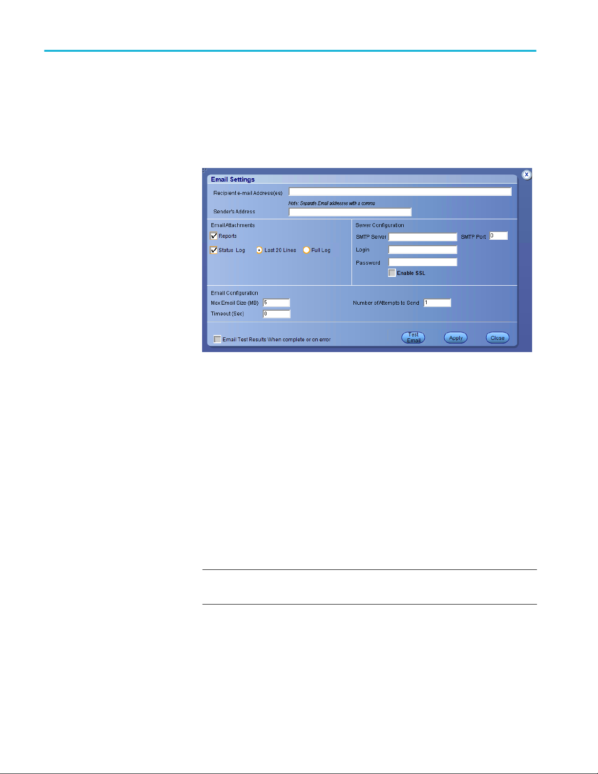
Configure email
notification
Set up these email settings if you want the application to notify you by email
when a test completes or produces an error. Configure email from the Options
menu.
1. From the Options menu in the upper right corner, select Email Settings to
open the Email Settings dialog box, or click the Preferences tab on the Setup
panel.
Figure 2: Email Settings dialog box
2. (Required) For Recipient email Address(es), enter your email address. You
can include multiple addresses as long as you separate the addresses with
commas.
3. (Required) For Sender's Address, enter the email address used by the
instrument. This address consists of the instrument name, followed by an
underscore, followed by the instrument serial number, the @ symbol, and the
email server used. For example: DPO72004C_B130099@yourcompany.com.
4. (Required) In the Server Configuration section, type the SMTP Server
address of the Mail server configured at the client location, and the SMTP
Port number, in the corresponding fields.
If this server requires password authentication, enter a valid login name,
password, and host name in the corresponding fields.
NOTE. If any of the above required fields are left blank, the settings will not
be saved and email notifications will not be sent.
5. In the Email Attachments section, select from the following options:
■
Reports: Select to receive the test report with the notification email.
22 TekExpress Automotive Ethernet
Page 33

Operating basics
■
Status Log: Select to receive the test status log with the notification
email. If you select this option, then also select whether you want to
receive the full log or just the last 20 lines.
NOTE. The ScoreCard and Analysis Screenshot options are not available
in Automotive Ethernet.
6. In the Email Configuration section, select as desired:
■
Enter a maximum file size for the email message. Messages with
attachments larger than this limit will not be sent. The default is 5 MB.
■
To limit the number of attempts the system makes to send a notification,
enter the number in the Number of Attempts to send field. The default is
1. You can also specify a timeout.
7. Select the Email Test Results when complete or on error check box. Use
this check box to quickly enable or disable email notifications.
8. To test your email settings, click Test Email.
9. To apply your settings, click Apply button.
10. Click Close button to exit the Email Settings dialog box.
See also. Before you click start
Pre-run check list
Running the tests and viewing their progress
TekExpress Automotive Ethernet 23
Page 34

Operating basics
Setup panel
Setup panel overview
The Setup panel contains sequentially ordered tabs that help you guide through
the test setup and execution process.
Figure 3: Setup panel
See also. Saving a test setup
Running the tests and viewing their progress in the Status Panel
Viewing test results in the Results Panel
24 TekExpress Automotive Ethernet
Page 35
Operating basics
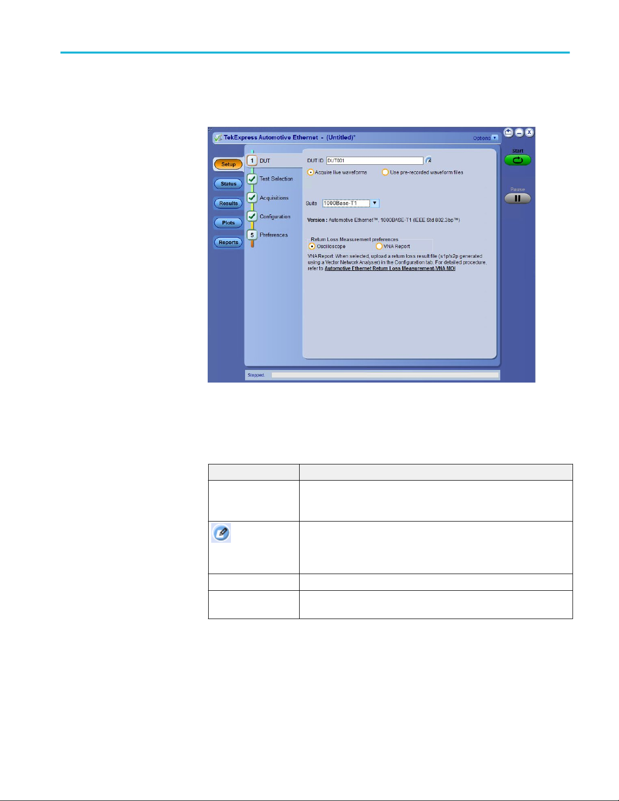
Set DUT tab parameters
Use the DUT tab to select parameters for the device under test. These settings are
global and apply to all tests for the current session. DUT settings also affect the
list of available tests in the Test Selection tab.
Figure 4: Setup panel
Click Setup > DUT to access the DUT parameters:
Table 9: DUT tab settings
Setting Description
DUT ID Adds an optional text label for the DUT to reports. The default value is
DUT001. The maximum number of characters is 32.
You cannot use the following characters in an ID name: (.,..,...,\,/:?”<>|*)
Opens a Comments dialog box in which you can enter optional text to
Comments icon
(to the right of the DUT
ID field)
Acquire live waveforms Perform analysis on live waveforms.
Use pre-recorded
waveform files
add to a report. Maximum size is 256 characters. To enable or disable
comments appearing on the test report. See Select report options for
details.
Perform analysis on pre-recorded waveforms.
TekExpress Automotive Ethernet 25
Page 36

Operating basics
Setting Description
Suite
■
1000Base-T1
■
100Base-T1
Selecting tests
Return Loss
measurement
preferences
■
Oscilloscope: Fully automated oscilloscope based method
■
VNA Report: Select to run the return loss measurement with a VNA
report file (S-Parameter). For steps to run the return loss
measurement by VNA Report file method, click here.
Only available, when Return Loss measurement is selected in the Test
Selection tab.
See also. Setup panel overview
Selecting tests
Setting configuration tab parameters
Use the Test Selection tab to select one or all the tests. The tests that you select
here impact the parameters available in the Acquisitions tab.
Figure 5: Test Selection tab
26 TekExpress Automotive Ethernet
Page 37

Operating basics
Table 10: Test selection tab settings
Setting Description
Tests Click on a test to select or unselect. Highlight a test to show
details in the Test Description pane.
Test Description Shows a brief description of the highlighted test in the test field.
Select All Click to select all the tests in the list.
Deselect All Click to deselect all the tests in the list.
Schematic Click to view the connection diagram for the selected test.
See also. Setup panel
Configuration tab
Status panel
Selecting acquisition tab
parameters
Use the Acquisitions tab to view test acquisition parameters. The contents
displayed on this tab depend on the pre-recorded or live mode selected.
TekExpress Automotive Ethernet 27
Page 38

Operating basics
Table 11: Acquisition tab settings
Setting Description
Probe<X> Select the channel connected to the probe.
Refresh Sources Click to refresh the selected resources.
Show Acquire
Parameters
Signal Validation Select the signal validation type
Select to view the acquisition parameters.
■
Prompt me if Signal Validation Fails
■
Skip test if Signal Validation Fails
■
Use signal as is - Don't Validate
TekExpress Automotive Ethernet saves all acquisition waveforms to files by
default. Waveforms are saved in a unique folder for each session (a session starts
when you click the Start button). The folder path is X:\Automotive-Ethernet
\Untitled Session \<dutid>\<date>_<time>. Images created for each analysis,
CSV files with result values, reports and other information specific to that
particular execution are also saved in this folder.
Saving a session moves the session file contents from the Untitled Session folder
to the specified folder name, and changes the session name to the specified name.
28 TekExpress Automotive Ethernet
Page 39

Operating basics
Acquire live waveforms for analysis. Select Acquire Live Waveforms on the
DUT tab, to perform live acquisitions.
Figure 6: Acquisitions tab with Acquire live waveforms selected
Table 12: Acquisitions tab settings for Acquire Live Waveforms
Column name Description
Probe<x> Select the probe source channel for each listed signal in the
Probe selection drop-down menu.
Refresh Sources Click to refresh the sources.
Show Acquire Parameters Select to view the acquisition parameters for the selected tests in
the results table.
TekExpress Automotive Ethernet 29
Page 40

Operating basics
Column name Description
Signal validation
■
Prompt me if signal fails: Select to prompt if signal fails.
■
Use Anyway: Click to Run the test on the current
acquired signal in spite of failed signal.
■
Skip Test: Click to skip the current test after signal
validation fails.
■
Reacquire: Click to reacquire the signal for the test
being Run.
■
Use signal as is-Don't check: Select to perform the test
without signal validation.
■
Skip test if signal fails:Select to skip the test for which
signal validation fails.
See also. Selecting configuration tab parameters
Use pre-recorded waveforms for analysis
30 TekExpress Automotive Ethernet
Page 41

Operating basics
Use pre-recorded waveforms for analysis. Select Use pre-recorded waveform
files on the DUT tab, to use pre-recorded waveforms for analysis. Click for
the selected measurement and select the waveform file (.wfm).
Figure 7: Acquisitions tab with Use pre-recorded waveform files selected
Table 13: Acquisitions tab settings for Use pre-recorded waveform files
Column name Description
Refresh Sources Click to refresh the sources.
Show Acquire Parameters Select to view the acquisition parameters for the selected tests in
the results table.
NOTE. Tektronix recommends to use a Tektronix oscilloscope to capture the
waveform files.
See also. Acquire live waveforms for analysis
TekExpress Automotive Ethernet 31
Page 42
Operating basics
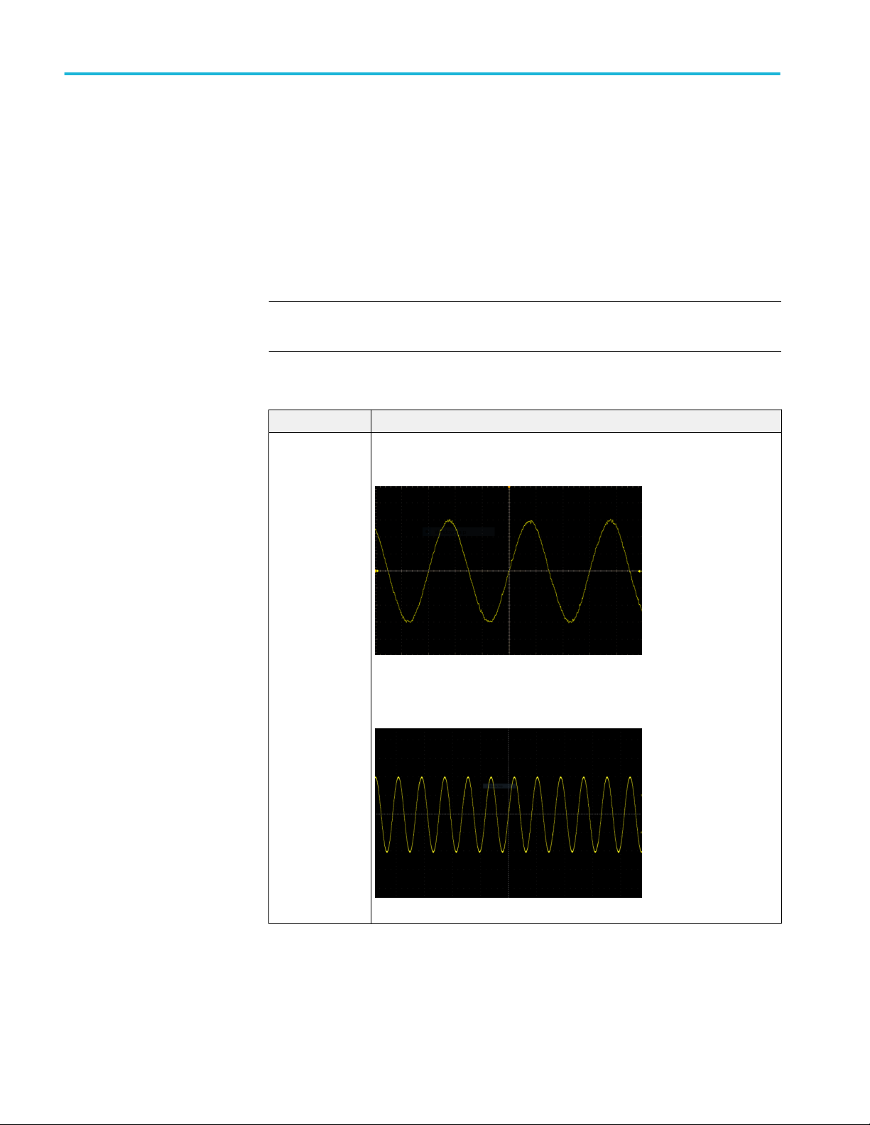
Acquire step by step. The Acquire Step By Step option is available in the
Acquisitions panel. This is a global parameter that is applied to all tests when
selected. By default, this option is deselected.
When selected, this parameter allows for display of the reference input waveform
of the selected measurement. This helps to compare the input waveform coming
from DUT with the typical reference waveform (snap shot), allowing you to
change the setup before acquiring the waveforms. The following table gives
different reference waveform snap shots that appear for different tests.
NOTE. When using prerecorded waveform files, the Acquire Step By Step option is not available.
Table 14: Reference waveforms
Test name Reference waveform
Transmit Timing
Jitter – Master
Jitter
100Base-T1
1000Base-T1
32 TekExpress Automotive Ethernet
Page 43

Operating basics
Test name Reference waveform
Transmit Timing
Jitter – Slave Jitter
100Base-T1
1000Base-T1
Transmit Timing
Jitter – MDI Jitter
1000Base-T1
TekExpress Automotive Ethernet 33
Page 44

Operating basics
Test name Reference waveform
Transmitter Output
Droop
100Base-T1
1000Base-T1
34 TekExpress Automotive Ethernet
Page 45

Operating basics
Test name Reference waveform
Transmit Clock
Frequency
100Base-T1
1000Base-T1
TekExpress Automotive Ethernet 35
Page 46

Operating basics
Test name Reference waveform
Transmitter
Distortion
100Base-T1
1000Base-T1
Transmitter Power
Spectral Density
100Base-T1
1000Base-T1
36 TekExpress Automotive Ethernet
Page 47

Operating basics
Test name Reference waveform
Transmitter Peak
Differential Output
100Base-T1
1000Base-T1
Return Loss 100Base-T1
1000Base-T1
TekExpress Automotive Ethernet 37
Page 48

Operating basics
Setting configuration tab
parameters
Use the Configuration tab to view the instruments detected, set measurement
parameters and perform calibration for the measurements.
Figure 8: Configure tab settings for 1000Base-T1
Figure 9: Configure tab settings for 100Base-T1
38 TekExpress Automotive Ethernet
Page 49

Operating basics
Table 15: Configuration tab settings
Setting Description
Compliance Mode Select to use Compliance Mode values. You cannot change any test
parameters in Compliance Mode, but you can view the compliance
parameters. By default Compliance Mode is selected.
User Defined Mode Select to run tests using custom parameters.
Limits Editor Shows the upper and lower limits for the applicable measurement using
different types of comparisons.
In Compliance Mode, use the Limits Editor to view the measurement high
and low limits used for selected tests.
In User Defined Mode, use the Limits Editor to edit the limit settings.
To edit a value, click that field and either select from the displayed list or
enter a new value. Use the bottom scroll bar to view all available fields.
Global Settings
Instruments Detected Displays the instruments connected to this application. Click on the
instrument name to open a list of available (detected) instruments.
Select Options > Instrument Control Settings and click Refresh to
update the instrument list.
NOTE. Verify that the GPIB/LAN search criteria (default setting) in the
Instrument Control Settings is selected when using TekExpress
Automotive Ethernet application.
VNA Result File Click Browse. Navigate to the folder path and select a return loss result
file (s1p/s2p) generated using a Vector Network Analyser.
Only available, when Return Loss measurement is selected in the Test
Selection tab.
Apply Band-pass Filter
for Jitter Measurements
Select to apply the Band pass filter for the selected jitter measurements.
Only available, either when one among Transmitter Timing Jitter - MDI
Jitter, Transmitter Timing Jitter - Master Jitter or Transmitter Timing
Jitter - Slave Jitter measurements or all these measurements are
selected in the Test Selection tab.
NOTE. Band pass filter is applicable only for 1000Base-T1 Jitter
Measurements and it is disabled for 100Base-T1.
The Configuration screen shows Global parameters, which are common for all
tests, and Measurement parameters, which are specific to selected tests, including
acquisition, analysis, and limit parameters.
TekExpress Automotive Ethernet 39
Page 50

Operating basics
NOTE. You cannot change the Test parameters that are greyed out.
See Also. Setup panel overview
Set DUT tab
Selecting tests
Selecting configuration tab
About saving and recalling test setups
40 TekExpress Automotive Ethernet
Page 51

Operating basics
Measurement parameter descriptions. You can view or change the measurement
parameters in the Configuration tab of the Setup panel. Configuration parameters
are displayed for the measurement selected, in the Test Selection tab. The
parameters listed are enabled based on the measurement selected and if the
measurements are running tests in User Defined Mode. You cannot change the
parameters in Compliance Mode.
1000Base-T1
Figure 10: Measurements tab
Table 16: 1000Base-T1 measurement configurations
Name Unit Range/
Allowable
values
Record Length M Samples 1 to 20 2.75 Sets the record
Default Description Applies to
Transmit Clock
length to use.
13 Transmitter
Frequency
Timing JitterMDI
Transmitter
Timing Jitter
(Master Jitter)
Transmitter
Timing Jitter
(Slave Jitter)
TekExpress Automotive Ethernet 41
Page 52

Operating basics
Name Unit Range/
Allowable
values
Averages NA 2 to 100 2 Sets the
2 to 1000 500 Return Loss
No of
Acquisitions
Hardware
Clock Divider
Software
Signal
Correction
None NA NA NA Select to check
NA 1 to 100 5 Sets the
NA NA Hardware
NA NA NA When Software
Default Description Applies to
number of
averages
(number of
acquisitions)
for average
mode
acquisition.
number of
acquisitions
Select to use
Clock Divider
the external
hardware clock
divider unit
(125 MHz
Tx_CLK to
10 MHz) to
synchronize
the DUT,
disturber signal
source (AWG/
AFG), and the
oscilloscope.
Signal
correction
method is
selected, the
software
computes Tx
distortion for
TM4 signal
with disturber
source without
using hardware
CDU
synchronizatio
n.
the behavior of
the DUT
without any Ref
clock (External
or Internal).
Transmitter
Output Droop
Transmitter
Peak
Differential
Output
Transmitter
Distortion
Transmitter
Distortion
Transmitter
Distortion
42 TekExpress Automotive Ethernet
Page 53

Operating basics
Name Unit Range/
Allowable
values
Unit of
Measurement
■
dBm
■
dBm/Hz
Edge
■
Falling
■
Rising
Hysteresis % 1 to 10 5 Sets the
Smooth NA 0 to 10 7 Sets the
NA NA dBm Selects the unit
NA NA Rising Used to select
Default Description Applies to
of
measurement
on which
Transmitter
Power Spectral
Density will be
displayed.
the type of
edges on
which RMS
Jitter and
Peak-to-Peak
Jitter will be
calculated.
hysteresis in
percentage
that gets used
during edge
finding.
number of
samples that
will be used
while
smoothing the
return loss
waveform; sets
the averaging
filter length.
Transmitter
Power Spectral
Density and
Power Level
Transmitter
Timing JitterMDI Jitter
Transmitter
Timing Jitter
(Master Jitter)
Transmitter
Timing Jitter
(Slave Jitter)
Transmitter
Timing Jitter
(Master Jitter)
Transmitter
Timing Jitter
(Slave Jitter)
Transmitter
Timing Jitter MDI Jitter
Return Loss
100Base-T1
TekExpress Automotive Ethernet 43
Page 54

Operating basics
Table 17: 100Base-T1 measurement configurations
Name Unit Range/
Allowable
values
Record Length M Samples 1 to 20 0.5 Sets the record
Averages NA 2 to 100 16 Sets the
2 to 1000 500
Spectral
Average
NA 2 to 256 2 Sets the
Default Description Applies to
length to use.
12.5 Transmitter
number of
averages
(number of
acquisitions)
for average
mode
acquisition.
number of
spectral
averages
Transmit Clock
Frequency
Timing Jitter
(Master Jitter)
Transmitter
Timing Jitter
(Slave Jitter)
Transmitter
Output Droop
Return Loss
Transmitter
Power Spectral
Density
44 TekExpress Automotive Ethernet
Page 55

Operating basics
Name Unit Range/
Allowable
values
Hardware
Clock Divider
Software
Signal
Correction
None NA NA NA Select to check
Edge
■
Falling
■
Rising
Hysteresis % 1 to 10 5 Sets the
NA NA NA Select to use
NA NA NA When Software
NA NA Rising Used to select
Default Description Applies to
the external
hardware clock
divider unit
(66.66 MHz
Tx_CLK to
10 MHz) to
synchronize
the DUT,
disturber signal
source (AWG/
AFG), and the
oscilloscope.
Signal
correction
method is
selected, the
software
computes Tx
distortion for
TM4 signal
with disturber
source without
using hardware
CDU
synchronizatio
n.
the behavior of
the DUT
without any Ref
clock (External
or Internal).
the type of
edges on
which RMS
jitter will be
calculated.
hysteresis in
percentage
that gets used
during edge
finding.
Transmitter
Distortion
Transmitter
Distortion
Transmitter
Distortion
Transmitter
Timing Jitter
(Master Jitter)
Transmitter
Timing Jitter
(Slave Jitter)
Transmitter
Timing Jitter
(Master Jitter)
Transmitter
Timing Jitter
(Slave Jitter)
TekExpress Automotive Ethernet 45
Page 56

Operating basics
Name Unit Range/
Allowable
values
RBW KHz 1 to 100 10 Sets the
Center
Frequency
Frequency
Span
Unit of
Measurement
■
dBm
■
dBm/Hz
Smooth NA 0 to 10 7 Sets the
MHz 50 to 500 100.5 Sets the center
MHz 100 to 500 201 Sets the range
NA NA dBm Selects the unit
Default Description Applies to
resolution
bandwidth.
This controls
the bandwidth
of the spectral
analyzer filters.
of the
frequency span
over which
spectral
analysis is
done.
of frequencies
over which
spectral
analysis is
done
of
measurement
on which
Transmitter
Power Spectral
Density will be
displayed.
number of
samples that
will be used
while
smoothing the
return loss
waveform; sets
the averaging
filter length.
Transmitter
Power Spectral
Density
Transmitter
Power Spectral
Density
Transmitter
Power Spectral
Density
Transmitter
Power Spectral
Density
Return Loss
See also. Setting configuration tab parameters
46 TekExpress Automotive Ethernet
Page 57

Operating basics
Calibration. Calibration step is done to calibrate the disturber signal source
amplitude and frequency. It measures the DUT signal level at defined PIN points
on the test fixture. You can perform calibration on live DUT signal and disturber
source signal connected as mentioned in the calibration connection diagram.
NOTE. It is recommended to do calibration of the waveforms for Transmitter
Distortion and Return Loss measurements.
Calibration for transmitter distortion measurement
Figure 11: Calibration tab for 1000Base-T1 transmitter distortion measurement
TekExpress Automotive Ethernet 47
Page 58

Operating basics
Figure 12: Calibration tab for 100Base-T1 transmitter distortion measurement
Calibration for return loss measurement
Figure 13: Calibration tab for return loss measurement
48 TekExpress Automotive Ethernet
Page 59

Operating basics
Table 18: Calibration settings
Parameter Description
Live Calibration Sets the live calibration process. The live Calibration files are
saved in X:\Automotive Ethernet\Calibration folder.
Use Pre-recorded Calibration Sets the calibration process with prerecorded calibrated
waveforms and allows you to browse and select the calibrated
waveforms. The path for selecting the calibrated waveforms is C:
\Users\Public\Tektronix\TekApplications\Automotive-Ethernet.
Channel drop down Allows you to select relevant channel and probes.
NOTE. when you change the input sources (Channel) other than
calibrated sources, you need to re-calibrate with latest sources.
Cal Type Displays the type of calibration: Load, Open, and Short.
Cal Status Displays the status of the calibration: Pending, Done.
Cal Time Displays the previous calibration time: Date, Month, and Year.
Schematic Click to view the schematic.
Plot Click to view the plot.
Apply Click to apply the configured parameters to calibration.
Run Click to run the process of calibration.
Default button Click to perform calibration by using default values.
NOTE. This button is applicable only for Transmitter distortion.
The expected and measured values for Transmitter distortion on
Calibration tab will be initially empty, when you launch the
application for the first time and they get populated once you
click the Default button.
To manually set up signal
source: Click here and copy
files to USB drive and recall on
connected signal source.
In case of manual signal source (AFG/AWG) setup, click the link
and copy the relevant folder and recall the setup on connected
signal source.
Compliance mode or User defined mode. From the Configuration screen, you will
have the option to select either Compliance Mode or User Defined Mode.
■
Compliance Mode: Select to use Compliance Mode values. You cannot
change any test parameters in Compliance Mode, but you can view the
compliance parameters.
■
User Defined Mode: Select to run tests using custom parameters. You may
change parameters that are not grayed out.
TekExpress Automotive Ethernet 49
Page 60

Operating basics
Set preferences tab
parameters
Use the Preferences tab to set the application action on completion of a
measurement.
Table 19: Preferences tab settings
Setting Description
Number of Runs
Acquire/Analyze each test Select to run the same selected test(s), specified number of
times. Minimum is two. Maximum is 30.
Actions on Test Measurement Failure
On Test Failure, stop and notify
me of the failure
Logging Options
Enable Logging Select to enable/disable the logging feature. When enabled the
Select to stop the test run on Test Failure, and to get notified via
email. By default, it is unselected.
Click Email Settings to configure.
application records the actions of the user. By default, it is
selected.
50 TekExpress Automotive Ethernet
Page 61

Operating basics
Setting Description
Hide schematic popup while
running the test (for single test
selection only)
When selected the schematic popup is displayed.
NOTE. When more than one test is selected, a warning message
will be displayed and the enabled check box will be ignored. The
schematics will be displayed for the selected measurements.
Does not apply for exceptions, VISA-connection timeout pop-ups.
Status panel overview
The Status button accesses the Test Status and Log View tabs, which provide
status on test acquisition and analysis (Test Status tab) and a listing of test tasks
performed (Log View tab). The application opens the Test Status tab when you
start a test run. You can select the Test Status or the Log View tab to view these
items while tests are running.
Test status view
TekExpress Automotive Ethernet 51
Page 62

Operating basics
Log view
Table 20: Status panel Log View controls
Control Description
Message History Lists all executed test operations and timestamp
information.
Auto Scroll Enables automatic scrolling of the log view as
information is added to the log during the test.
Clear Log Clears all messages from the log view.
Save Saves the log file to a text file. Use the standard
Save File window, to navigate and specify the
folder and file name and then save the log file.
52 TekExpress Automotive Ethernet
Page 63

Operating basics
Results panel
Viewing test results: the
Results panel
When a test completes running, the application switches to the Results Panel.
Set result viewing preferences from the Preferences menu in the upper right
corner.
Each test result occupies a row in the Results table. By default, results are
displayed in summary format, with the measurement details collapsed, and with
the Pass/Fail column visible. You can change the display view.
■
To expand all test rows listed, from the Preferences menu in the upper right
corner, select View Results Details.
■
To expand a collapsed test row, click the plus button (
) to the left of the
test row.
■
To collapse all expanded test rows, select Preferences > View Results
Summary.
■
To collapse a single expanded test row, click the minus button (
) to the left
of the test row.
■
To remove or restore the Pass/Fail column, select Preferences > Show Pass/
Fail.
■
To enable or disable the wordwrap feature, select Preferences > Enable
Wordwrap.
■
To expand the width of a column, place the cursor over the vertical line that
separates the column from the one to the right. When the cursor changes to a
double-ended arrow, hold down the mouse button and drag the column to the
desired width.
■
To sort the test information by column, click the column head. When sorted
in ascending order, a small up arrow is displayed. When sorted in descending
order, a small down arrow is displayed.
■
To clear all test results displayed, click Clear
button.
TekExpress Automotive Ethernet 53
Page 64

Operating basics
Results preferences
View test-related Files
Figure 14: Results preferences
See also. Setup panel
Running tests and viewing their progress: the Status panel
Files related to TekExpress Automotive Ethernet tests are stored in the X:
\Automotive Ethernet\Untitled Session shared folder. In the Automotive Ethernet
folder, each test setup has a test setup file and a test setup folder, both with the
test setup name. The test setup file is preceded by the Automotive Ethernet icon
and usually has no file extension displayed.
Inside the test setup folder is another folder named for the DUT ID used in the
test sessions (the default is DUT001).
Inside the DUT001 folder are the session folders and files. Each session has a
folder and file pair, both named for the test session using the naming convention
(date)_(time). Each session file is stored outside of its matching session folder.
Each session folder contains image files of any plots generated by the test session
and any waveform files if prerecorded waveform files were used during the
session.
54 TekExpress Automotive Ethernet
Page 65

Plots panel
Operating basics
The first time you run a new, unsaved session, the session files are stored in the
X:\Automotive Ethernet\Untitled Session folder. Once you name and save the
session, the Untitled Session folder name is changed to the one you specified.
NOTE. By default, test report files are saved in the session folder. You can change
the report file location for a specific test.
See also. File name extensions
Viewing plots
The Plots panel displays a summary of plot generated during run. The plots have
zoom, cursors, save, dock/undock, and select test features.
Types of plots
Following are different plots generated during run, based on the measurement(s)
selected.
Transmit Clock Frequency
Figure 15: Transmit Clock Frequency - 1000Base-T1 Histogram Plot
TekExpress Automotive Ethernet 55
Page 66

Operating basics
Figure 16: Transmit Clock Frequency - 1000Base-T1
Figure 17: Transmit Clock Frequency - 100Base-T1
56 TekExpress Automotive Ethernet
Page 67

Operating basics
Transmitter Timing Jitter (Master and Slave)
Figure 18: Master Jitter - 1000Base-T1 Histogram plot
Figure 19: Master Jitter - 1000Base-T1
TekExpress Automotive Ethernet 57
Page 68

Operating basics
Figure 20: Master Jitter - 100Base-T1
Figure 21: Slave Jitter - 1000Base-T1 Slave Histogram plot
58 TekExpress Automotive Ethernet
Page 69

Operating basics
Figure 22: Slave Jitter - 1000Base-T1
Figure 23: Slave Jitter - 100Base-T1
TekExpress Automotive Ethernet 59
Page 70

Operating basics
Transmitter Output Droop
Figure 24: Transmitter Output Droop - 1000Base-T1: Positive
Figure 25: Transmitter Output Droop - 1000Base-T1: Negative
60 TekExpress Automotive Ethernet
Page 71

Operating basics
Figure 26: Transmitter Output Droop - 100Base-T1: Positive
Figure 27: Transmitter Output Droop - 100Base-T1: Negative
TekExpress Automotive Ethernet 61
Page 72

Operating basics
Transmitter Power Spectral Density
Figure 28: Transmitter Power Spectral Density and Power Level - 1000Base-T1
Figure 29: Transmitter Power Spectral Density - 100Base-T1
62 TekExpress Automotive Ethernet
Page 73

Operating basics
Transmitter Distortion
Figure 30: Error Value - 1000Base-T1
Figure 31: Error Value - 100Base-T1
TekExpress Automotive Ethernet 63
Page 74

Operating basics
Figure 32: Peak Distortion - 1000Base-T1
Figure 33: Peak Distortion - 100Base-T1
64 TekExpress Automotive Ethernet
Page 75

Operating basics
Return Loss
Figure 34: Return Loss - 1000Base-T1
Figure 35: Return Loss - 100Base-T1
TekExpress Automotive Ethernet 65
Page 76

Operating basics
Figure 36: 100Base-T1 Return Loss Load Calibration
Figure 37: 100Base-T1 Return Loss Short Calibration
66 TekExpress Automotive Ethernet
Page 77

Operating basics
Figure 38: 100Base-T1 Return Loss Open Calibration
Figure 39: 1000Base-T1 Return Loss Load Calibration
TekExpress Automotive Ethernet 67
Page 78

Operating basics
Figure 40: 1000Base-T1 Return Loss Short Calibration
Figure 41: 1000Base-T1 Return Loss Open Calibration
See also. Known limitations
68 TekExpress Automotive Ethernet
Page 79

Operating basics
Reports panel
Reports panel overview
Use the Reports panel to browse for reports, name and save reports, select test
content to include in reports, and select report viewing options.
Report contents
Figure 42: Reports panel
For information on setting up reports, see Select report options. For information
on viewing reports, see View a report.
A report shows detailed results and plots, as set in the Reports panel.
TekExpress Automotive Ethernet 69
Page 80

Operating basics
Figure 43: Example report for single run
70 TekExpress Automotive Ethernet
Page 81

Operating basics
TekExpress Automotive Ethernet 71
Page 82

Operating basics
Figure 44: Example report for multi-run
Setup configuration information
The summary box at the beginning of the report lists setup configuration
information. This information includes the oscilloscope model and serial number,
optical module model and serial number, and software version numbers of all
associated applications.
To exclude this information from a report, clear the Include Setup
Configuration check box in the Reports panel before running the test.
User comments
If you selected to include comments in the test report, any comments you added
in the DUT tab are shown at the top of the report.
72 TekExpress Automotive Ethernet
Page 83

Operating basics
See also. Results panel
View test-related files
Select report options
Click the Reports button and use the Reports panel controls to select which test
result information to include in the report, and the naming conventions to use for
the report. For example, always give the report a unique name or select to have
the same name increment each time you run a particular test.
Select report options before running a test or when creating and saving test
setups. Report settings are included in saved test setups.
In the Reports panel, select from the following report options:
Table 21: Report options
Setting Description
Report Update Mode
Generate new report Creates a new report. The report can be in
either .mht or .pdf or .csv file formats.
Append with previous run session Appends the latest test results to the end of the
current test results report.
Replace current test in previous run session Replaces the previous test results with the latest
test results. Results from newly added tests are
appended to the end of the report.
Report Creation Settings
TekExpress Automotive Ethernet 73
Page 84

Operating basics
Setting Description
Report name Displays the name and location from which to
open a Ethernet Tx report. The default location
is at \My TekExpress\Automotive Ethernet
\Untitled Session. The report file in this folder
gets overwritten each time you run a test unless
you specify a unique name or select to auto
increment the report name.
Change the report name or location.
Do one of the following:
■
In the Report Path field, type over the
current folder path and name.
■
Double-click in the Report Path field and
then make selections from the popup
keyboard and click the Enter button.
Be sure to include the entire folder path, the file
name, and the file extension. For example: C:
\Documents and Settings\your user name\My
Documents\My TekExpress\Automotive Ethernet
\DUT001.mht.
NOTE. You cannot set the file location using the
Browse button.
Open an existing report.
Click Browse, locate and select the report file
and then click View at the bottom of the panel.
Save as type Saves a report in the specified file type, selected
from the drop-down list.
NOTE. If you select a file type different from the
default, be sure to change the report file name
extension in the Report Name field to match.
Auto increment report name if duplicate Sets the application to automatically increment
the name of the report file if the application finds
a file with the same name as the one being
generated. For example: DUT001, DUT002,
DUT003. This option is enabled by default.
Create report automatically at the end of the run Creates report at the end of the run.
Contents To Save
Include pass/fail info in details table Includes pass/fail info in the details table of the
report.
Include detailed results Includes detailed results in the report.
Include plot images Includes plot images in the report.
74 TekExpress Automotive Ethernet
Page 85

Setting Description
Include setup configuration Sets the application to include hardware and
software information in the summary box at the
top of the report. Information includes: the
oscilloscope model and serial number, the
oscilloscope firmware version, and software
versions for applications used in the
measurements.
Include complete application configuration Includes complete application configuration in
the report.
Include user comments Select to include any comments about the test
that you or another user added in the DUT tab of
the Setup panel. Comments appear in the
Comments section, under the summary box at
the beginning of each report.
Group Report By
Test Name Select to group the tests in the report by test
name.
Test Result Select to group the tests in the report by test
results
View report after generating Automatically opens the report in a Web browser
when the test completes. This option is selected
by default.
View Click to view the most current report.
Generate Report Generates a new report based on the current
analysis results.
Save As Specify a name for the report.
Operating basics
View a report
The application automatically generates a report when test analysis is completed
and displays the report in your default Web browser (unless you cleared the View
Report After Generating check box in the Reports panel before running the
test). If you cleared this check box, or to view a different test report, do the
following:
1. Click the Reports button.
2. Click the Browse button and locate and select the report file to view.
3. In the Reports panel, click View.
For information on changing the file type, file name, and other report options, see
Select report options.
TekExpress Automotive Ethernet 75
Page 86

Operating basics
76 TekExpress Automotive Ethernet
Page 87

Running tests
Automate AWG/AFG signal generation
The TekExpress Automotive Ethernet application allows you to automatically
load the pattern files in AWG/AFG and generate the signals. Ensure that the
GPIB/LAN/USB connection between the oscilloscope and AWG/AFG is
established, before you automate the signal generation. The AWG/AFG
automation is supported for the following measurements:
■
Transmitter Distortion with disturbing signal: AWG/AFG is used to transmit
a disturbing signal. CH1 and CH1_inverted are used.
■
Return Loss measurement and calibration: AWG/AFG is used to transmit a
wide band signal. CH1 and CH1_inverted are used for transmission of the
signal. A marker signal has to be connected to the auxiliary channel of the
oscilloscope (used as trigger source).
How to automate AWG/AFG signal generation
Complete the following steps in the TekExpress application to automate the
signal generation from AWG/AFG:
1. Click in the upper right corner of the application and select Instrument
Control Settings.
2. Select Search Criteria as USB and click Refresh; when the Retrieved
Instruments table is uploaded with the connected instruments list, click
Close.
Figure 45: Instrument Control Settings
TekExpress Automotive Ethernet 77
Page 88

Running tests
3. Once the AWG/AFG is listed as shown above, go to the Global Settings tab
from the Configuration menu of the Tests. If the AWG/AFG is supported, it
will be listed as a drop-down menu option next to the Automate with AWG/
AFG label. By default, the application will consider the connected AWG to
be used for automation.
Figure 46: Test Selection tab
NOTE. If Automate with AWG/AFG is set as Do not use, you must manually copy
the AWG/AFG waveforms from the oscilloscope to the AWG/AFG. Waveforms
are located at C:\Program Files\Tektronix\TekExpress\TekExpress AutomotiveEthernet\AWG Waveforms\.
78 TekExpress Automotive Ethernet
Page 89

Running tests
Before you click start
Before running a test for the first time
Before you run a test for the first time, review these steps:
1. Understand where your test files are stored on the instrument.
After you install and launch TekExpress Automotive Ethernet, it creates the
following folders on the Oscilloscope:
■
\Program Files\Tektronix\TekExpress\TekExpress Automotive-Ethernet
■
\My Documents\My TekExpress\Automotive Ethernet
■
\My Documents\My TekExpress\Automotive Ethernet\Untitled Session
Every time you launch TekExpress Automotive Ethernet.exe, an Untitled
Session folder is created in the Automotive Ethernet folder. The Untitled
Session folder is automatically deleted when you exit the Automotive
Ethernet application.
CAUTION. Do not modify any of the session files or folders because this may
result in loss of data or corrupted session files. Each session has multiple files
associated with it. When you save a session, a .TekX file, and a folder named for
the session that contains the associated files, is created on the oscilloscope X:
drive.
2.
Ensure that the My TekExpress folder has read and write access, and that
the contents are not set to be encrypted:
a. Right-click the folder and select Properties.
b. Select the General tab, and then click Advanced.
c. In the Advanced Attributes dialog box, ensure that the option Encrypt
contents to secure data is NOT selected.
TekExpress Automotive Ethernet 79
Page 90

Running tests
Example:
Figure 47: Advanced Attributes dialog box
Before running any test
1. Review the Pre-run check list.
2. Configure the Email notification options if you want the application to notify
you by email when a test completes or produces an error. Access the email
options either from the Options menu in the upper right corner, or from the
Preferences tab on the Setup panel.
3. Select the Report options.
See Also
Pre-run check list
80 TekExpress Automotive Ethernet
Page 91

Running tests
Pre-run check list
Do the following before you click Start to run a test. If this is the first time you
are running a test on a setup, then refer also to the guidelines above.
1. Ensure that all the required instruments are properly warmed up (about
20 minutes).
2. Perform the Signal Path Compensation (SPC).
a. On the oscilloscope main menu, select the Utilities menu.
b. Select Instrument Calibration.
3. Deskew any cables.
4. Ensure that the application is able to find the DUT. If it cannot, perform a
search for connected instruments.
To find the DUT:
a. Launch the TekExpress Automotive Ethernet application.
b. Select the Setup panel and then click the DUT tab.
See also
c. Click the Test Selection tab. Select any test, and then click Configure
button.
d. In the Configuration section, click Global Settings.
e. In the Instruments Detected section, click in the shaded area opposite Real
Time Scope and ensure that the oscilloscope with the (GPIB8::1::INSTR)
designation is in the drop-down list.
Before you click start
Configure email notification
Running the tests and viewing their progress
TekExpress Automotive Ethernet 81
Page 92

Running tests
Running the tests and viewing their progress: the Status panel
Once you have configured the tests and gone through the Pre-run check list, from
any screen, click the green Start button. The application acquires and analyzes
the data, then displays a report when the tests are completed.
While the tests are running, other applications may display windows in the
background. The TekScope application takes precedence over other applications,
but you can switch to other applications using the Alt+Tab key combination. To
keep the TekExpress Automotive Ethernet application on top, select the Keep On
Top from the Options menu in the upper right corner.
Viewing the progress of
analysis
The Status panel displays a record of the test as it is executed. By default, the
application switches to this panel after you click the Start button to run a test.
You can choose from the following two views by selecting the named tab, even
while a test is in progress:
Test Status tab
Figure 48: Test status tab
The Test Status tab presents a collapsible table with information about each test
as it is running. To collapse and expand the table rows, click the expand ( )/( )
collapse button.
82 TekExpress Automotive Ethernet
Page 93

Running tests
Table 22: Test Status table headers
Column Description
Test Name Name of the test
Acquisition Describes the type of data being acquired
Acquire Status Progress of the acquisition:
■
To be started
■
Started Acquisition
■
Completed Acquisition
Analysis Status Progress state of the analysis:
■
To be started
■
In Progress
■
Completed
■
Aborted
Log View tab
■
Skipped
Figure 49: Log view
The Log View tab provides a list of actions that happen as the test executes. You
can use this tab to review or troubleshoot tests.
TekExpress Automotive Ethernet 83
Page 94

Running tests
Table 23: Log view options
Item Description
Message History This window time-stamps and displays all run
messages.
Auto Scroll Select this check box to have the program
automatically scroll down as information is
added to the log during test execution.
Clear Log Click this button to clear all messages in the
Message History area.
Save Use to save the log file as a text file for
examination. Displays a standard Save File
window and saves the status messages file that
you specify.
See also
Before you click start
Pre-run check list
Configure email notification
84 TekExpress Automotive Ethernet
Page 95

Saving and recalling test setups
About saving and recalling test setups
TekExpress Automotive Ethernet application opens with the default test setup
selected. Any time you want to create a new test setup, you can select the default
test setup to clear the previous test setup selections and take the settings back to
their defaults.
You can run a test before or after saving a setup. When you save a setup, the
selected oscilloscope, general parameters, acquisition parameters, measurement
limits, prerecorded waveform files (if applicable), test, and other configuration
settings are all saved under the setup name. You can open a setup and click Start
button without having to do any other setting up except ensuring that the
oscilloscope is detected and ready. For details, see Before you click start.
See Also
Save a test setup
Recall a saved test setup
Create a new test setup based on an existing one
Delete a test setup
Setup panel overview
TekExpress Automotive Ethernet 85
Page 96

Saving and recalling test setups
Saving a test setup
Save a test setup before or after running a test using the parameters you want to
be saved. You can create a new setup from any setup you have open or from the
default setup. When you select the default test setup, all parameters are returned
to their defaults. The following instructions start from the default setup:
1. From the Options menu, select Default Test Setup.
2. Select the desired options in the Setup panel.
3. Select the desired report options.
4. If desired, run the test to ensure that it captures the information you want. If it
does not, edit the parameters.
5. From the Options menu, select Save Test Setup.
6. Name the test and, then click Save button.
See Also
About test setups
Recall a saved test setup
Create a new test setup based on an existing one
Delete a test setup
Recalling a saved test setup
These instructions are for recalling saved test setups.
1. From the Options menu, select Open Test Setup.
2. In the File Open dialog box, select the desired setup from the list, and then
click Open button.
See also
About test setups
Save a test setup
Create a new test setup based on an existing one
Delete a test setup
86 TekExpress Automotive Ethernet
Page 97

Creating a new test setup based on an existing one
Use this method to create a variation on a test setup without having to create the
setup from the beginning.
1. From the Options menu, select Open Test Setup.
2. In the File Open dialog box, select the desired setup from the list, and then
click Open.
3. Modify the parameters as desired.
4. From the Options menu, select Save Test Setup As.
5. In the File Save As dialog box, enter a test setup name, and then click Save.
See also
About test setups
Save a test setup
Recall a saved test setup
Saving and recalling test setups
Deleting a test setup
Delete a test setup
If you no longer need a test setup, delete it from the test setup list in the Options
menu using these instructions.
Each saved test setup consists of two main parts, the test setup file and the test
setup folder, both named for the test session.
1. Ensure the setup you want to delete is not currently selected in TekExpress
Automotive Ethernet.
2. Navigate to the Automotive Ethernet folder where test setup files are stored.
For example, X:\Automotive Ethernet\(test setup name).
3. Locate the test setup file, and then delete it.
This removes the setup from the list in the Options menu.
4. Locate the test setup folder. If you want to keep any of the session files,
move them out of the test setup folder and then delete the test setup folder.
See also
About test setups
Save a test setup
Recall a saved test setup
Create a new test setup based on an existing one
TekExpress Automotive Ethernet 87
Page 98

Saving and recalling test setups
88 TekExpress Automotive Ethernet
Page 99

Automotive Ethernet measurements
Transmitter clock frequency
This measurement verifies that the frequency of the transmit clock is within the
conformance limits.
Suite Description
1000Base-T1 Physical Layer Specifications (IEEE Std
100Base-T1 BroadR-Reach Physical Layer Transceiver
802.3bp™-2016) a parameter for 1 Gb/s
Operation over a Single Twisted-Pair Copper
Cable section 97.5.3.6 Transmitter clock
frequency test.
Specification for Automotive Applications,
version 3.2, section 5.1.3 or IEEE P802d3bw
(100 Base T1) section 96.5.4.5 transmitter
specifications
BroadR-Reach Physical Media Attachment Test
Suite version 2.0, section 5.5
TM
Required test equipment
In addition to the DUT and oscilloscope, you need the following:
■
One supported differential probe
■
Short automotive cable.
■
TF-XGbT test fixture
TekExpress Automotive Ethernet 89
Page 100

Automotive Ethernet measurements
Figure 50: Connection diagram
NOTE. Ensure that the probe tip (+) is connected to the on the text fixture
board.
Test setup procedure
1. Make the connection as shown in the above connection diagram.
2. Select the Suite type on the DUT panel.
90 TekExpress Automotive Ethernet
 Loading...