

Page 1

User Manual
CSA7404 & CSA7154
Communications Signal Analyzers,
TDS7404, TDS7254, TDS7154, TDS7104, & TDS7054
Digital Phosphor Oscilloscopes, &
TDS6604 & TDS6404 Digital Storage Oscilloscopes
071-7010-02
This document supports firmware version 2.3.0
and above.
www.tektronix.com
Page 2

Copyright © Tektronix, Inc. All rights reserved.
Tektronix products are covered by U.S. and foreign patents, issued and pending. Information in this publication supercedes
that in all previously published material. Specifications and price change privileges reserved.
Tektronix, Inc., P.O. Box 500, Beaverton, OR 97077-0001
TEKTRONIX and TEK are registered trademarks of Tektronix, Inc.
TekConnect, TekVISA, FastFrame, and VocalLink are registered trademarks of Tektronix, Inc.
Page 3

WARRANTY
Tektronix warrants that the products that it manufactures and sells will be free from defects in materials and
workmanship for a period of one (1) year from the date of shipment. If this product proves defective during its
warranty period, Tektronix, at its option, will either repair the defective product without charge for parts and labor,
or provide a replacement in exchange for the defective product.
This warranty applies only to products returned to the designated Tektronix depot or the Tektronix authorized
representative from which the product was originally purchased. For products returned to other locations,
Customer will be assessed an applicable service charge. The preceding limitation shall not apply within the
European Economic Area, where products may be returned for warranty service to the nearest designated service
depot regardless of the place of purchase.
In order to obtain service under this warranty, Customer must provide the applicable office of Tektronix or its
authorized representative with notice of the defect before the expira tion of the warranty period and make suitable
arrangements for the performance of service. Customer shall be responsible for packaging and shipping the
defective product to the service center designated by Tektronix or its representative, with shipping charges
prepaid. Tektronix or its representative shall pay for the return of the product to Customer. Customer shall be
responsible for paying any associated taxes or duties.
This warranty shall not apply to any defect, failure or damage caused by improper use or improper or inadequate
maintenance and care. Tektronix shall not be obligated to furnish service under this warranty:
a) to repair damage resulting from attempts by personnel other than Tektronix representatives to install, repair or
service the product;
b) to repair damage resulting from improper use or connection to incompatible equipment;
c) to repair any damage or malfunction caused by the use of non-Tektronix supplies or consumables;
d) to repair a product that has been modified or integrated with other products when the effect of such
modification or integration increases the time or difficulty of servicing the product; or
e) to repair damage or malfunction resulting from failure to perform user maintenance and cleaning at the
frequency and as prescribed in the user manual (if applicable).
THE ABOVE WARRANTIES ARE GIVEN BY TEKTRONIX WITH RESPECT TO THIS PRODUCT IN LIEU OF
ANY OTHER WARRANTIES, EXPRESS OR IMPLIED. TEKTRONIX AND ITS VENDORS DISCLAIM ANY
IMPLIED WARRANTIES OF MERCHANTABILITY OR FITNESS FOR A PARTICULAR PURPOSE. TEKTRONIX’
RESPONSIBILITY TO REPAIR OR REPLACE DEFECTIVE PRODUCTS IS THE SOLE AND EXCLUSIVE
REMEDY PROVIDED TO THE CUSTOMER FOR BREACH OF THIS WARRANTY. TEKTRONIX AND ITS
VENDORS WILL NOT BE LIABLE FOR ANY INDIRECT, SPECIAL, INCIDENTAL, OR CONSEQUENTIAL
DAMAGES IRRESPECTIVE OF WHETHER TEKTRONIX OR THE VENDOR HAS ADVANCE NOTICE OF THE
POSSIBILITY OF SUCH DAMAGES.
Page 4

Page 5

Table of Contents
Getting Started
General Safety Summary xiii...................................
Preface xv...................................................
About This Manual xv...............................................
Related Manuals and Online Documents xvi..............................
Contacting Tektronix xvii.............................................
Product Description 1--1........................................
Models 1--1........................................................
Key Features 1--2....................................................
Product Software 1--3................................................
Software Upgrade 1--4................................................
Installation 1--5...............................................
Unpacking 1--6......................................................
Checking the Environment Requirements 1--7.............................
Connecting Peripherals 1--7............................................
Powering On the Instrument 1--9........................................
Shutting Down the Instrument 1--10......................................
Creating an Emergency Startup Disk 1--11.................................
Backing Up User Files 1--11............................................
Installing Software 1--12...............................................
Enabling Your LAN and Connecting to a Network 1--15......................
Setting up a Dual Display 1--17..........................................
Incoming Inspection 1--21.......................................
Assemble Equipment 1--21.............................................
Self Tests 1--22.......................................................
Functional Tests 1--23.................................................
Check Vertical Operation 1--24......................................
Check Horizontal Operation 1--28....................................
Check Trigger Operation 1--30.......................................
Check File System 1--32............................................
Perform the Extended Diagnostics 1--35...................................
Accessories & Options 1--37......................................
Options 1--37........................................................
Accessories 1--39.....................................................
CSA7000 Series, TDS7000 Series, & TDS6000 Series Instruments User Manual
i
Page 6

Table of Contents
Operating Basics
Reference
Operational Maps 2--1.........................................
Documentation Map 2--2.......................................
System Overview Maps 2--4.....................................
Functional Model Map 2--4............................................
Process Overview Map 2--6............................................
User Interface Map -- Complete Control and Display 2--7............
Front-Panel Map -- Quick Access to Most Often Used Features 2--8....
Display Map -- Single Graticule 2--9..............................
Front Panel I/O Map 2--10.......................................
Rear Panel I/O Map 2--11.......................................
Overview 3--1.................................................
Acquiring Waveforms 3--7......................................
Signal Connection and Conditioning 3--8.................................
Connecting and Conditioning Your Signals 3--10........................
To Set Up Signal Input 3--13........................................
To Autoset the Instrument 3--17......................................
To Reset the Instrument 3--18........................................
To Get More Help 3--19............................................
Input Conditioning Background 3--19.................................
Setting Acquisition Controls 3--26.......................................
Using the Acquisition Controls 3--28..................................
To Set Acquisition Modes 3--34......................................
To Start and Stop Acquisition 3--37...................................
To Set Roll Mode 3--38............................................
Acquisition Control Background 3--39....................................
Acquisition Hardware 3--40.........................................
Sampling Process 3--40.............................................
Acquisition Modes 3--41............................................
Waveform Record 3--41............................................
Real-Time Sampling 3--42..........................................
Equivalent-Time Sampling 3--43.....................................
Interpolation 3--45................................................
Interleaving 3--46.................................................
Using Fast Acquisition Mode 3--47.......................................
Using Fast Acquisitions 3--48........................................
To Turn Fast Acquisitions On and Off 3--50............................
To Set Display Format 3--54.........................................
ii
CSA7000 Series, TDS7000 Series, & TDS6000 Series Instruments User Manual
Page 7

Table of Contents
Using FastFrame 3--56.................................................
Using FastFrame Acquisitions 3--57..................................
To Set FastFrame Mode 3--58.......................................
Time Stamping Frames 3--60........................................
O/E Converter 3--63...................................................
Connecting Optical Signals 3--63.....................................
Attenuating Optical Signals 3--64....................................
Front Panel Connectors 3--64...........................................
Optical Input Connector 3--64.......................................
Output Connectors 3--64............................................
O/E Electrical Out-to-Ch1 Input Adapter 3--65..........................
O/E-to-SMA Adapter 3--66.........................................
Cleaning Optical Connectors 3--66...................................
Optical Dark Compensation 3--67....................................
Compensation 3--67...............................................
Wavelength, Filter, and Bandwidth Selection 3--67..........................
Optical Bandwidth 3--68...............................................
Bandwidth for Unfiltered Settings 3--70...............................
Bandwidth for Reference Receiver settings 3--70........................
Triggering 3--71................................................
Triggering Concepts 3--72..............................................
The Trigger Event 3--73............................................
Trigger Sources 3--73..............................................
Trigger Types 3--73................................................
Trigger Modes 3--74...............................................
Trigger Holdoff 3--75..............................................
Trigger Coupling 3--76.............................................
Horizontal Position 3--77...........................................
Slope and Level 3--77..............................................
Delayed Trigger System 3--78.......................................
Triggering from the Front Panel 3--78.....................................
Access Procedures 3-- 78............................................
To Check Trigger Status 3--82.......................................
Additional Trigger Parameters 3--83......................................
Advanced Triggering 3--88.............................................
To Trigger on a Glitch 3--94.........................................
To Trigger on a Runt Pulse 3--96.....................................
Trigger Based on Pulse Width 3--99...................................
To Trigger Based on Transition Time 3--101.............................
Trigger Based on Pulse Timeout 3--104.................................
Trigger on a Pattern 3--105...........................................
To Trigger on a State 3--109..........................................
To Trigger on Setup/Hold Time Violations 3--110.........................
CSA7000 Series, TDS7000 Series, & TDS6000 Series Instruments User Manual
iii
Page 8

Table of Contents
Sequential Triggering 3--113.............................................
Using Sequential Triggering 3--114....................................
To Trigger on a Sequence 3--118......................................
Comm Triggering 3--122................................................
Serial Pattern Triggering 3--122..........................................
Displaying Waveforms 3--123......................................
Using the Waveform Display 3--124.......................................
Using the Display 3--125............................................
To Display Waveforms in the Main Graticule 3--129......................
Setting MultiView Zoom Controls 3--131...................................
Using with Waveforms 3-- 132........................................
To Zoom Waveforms 3--132..........................................
Customizing the Display 3--138..........................................
Using Display Controls 3--138........................................
Set Display Styles 3--141............................................
Customize Graticule and Waveforms 3--144.............................
Measuring Waveforms 3--147.....................................
Taking Automatic Measurements 3--148....................................
Using Automatic Measurements 3--150.................................
To Take Automatic Measurements 3--153...............................
To Localize a Measurement 3--159....................................
Taking Cursor Measurements 3--160.......................................
Using Cursors 3--162...............................................
To Set the Cursor Sources 3--165......................................
Taking Histograms 3--168...............................................
Using Histograms 3--169............................................
To Start and Reset Histogram Counting 3--169...........................
Histogram Measurements 3-- 171......................................
Optimizing Measurement Accuracy 3--171..................................
To Compensate the Instrument 3--172..................................
To Connect the Probe Calibration Fixture 3--173.........................
To Calibrate Probes 3--177...........................................
To Compensate Passive Probes 3--180..................................
To Deskew Channels 3--181..........................................
Serial Mask Testing 3--184..............................................
Creating and Using Math Waveforms 3--185.........................
Defining Math Waveforms 3--186.........................................
Using Math 3--188.................................................
To Define a Math Waveform 3--194....................................
Operations on Math Waveforms 3--197.....................................
Using Math Waveforms 3--197........................................
To Use Math Waveforms 3--198.......................................
iv
CSA7000 Series, TDS7000 Series, & TDS6000 Series Instruments User Manual
Page 9

Table of Contents
Defining Spectral Math Waveforms 3--202..................................
Using Spectral Math Controls 3--203...................................
Recognizing Aliasing 3--227.........................................
To Select a Predefined Spectral Math Waveform 3--230....................
To Define a Spectral Math Waveform 3--231............................
Spectral Math Example 3--239........................................
Data Input/Output 3--245.........................................
Saving and Recalling a Setup 3-- 245.......................................
Using Auto-Increment File Name 3--247................................
To Save Your Setup 3--248...........................................
To Recall Your Setup 3--251..........................................
Saving and Recalling Waveforms 3--253...................................
To Save Your Waveform 3--254.......................................
To Recall Your Waveform 3--257......................................
To Clear References 3--260..........................................
Exporting and Copying Waveforms 3--262..................................
To Export Your Waveform 3--263.....................................
To Use an Exported Waveform 3--271..................................
To Copy Your Waveform 3--273......................................
Printing Waveforms 3--277..............................................
To Print from Front Panel 3--277......................................
To Print from Menu Bar 3--277.......................................
To Set Up the Page 3--278...........................................
To Preview the Page 3--279..........................................
To Print Using Print Screen 3--280.....................................
To Date/Time Stamp Hardcopies 3--281................................
Remote Communication 3--282...........................................
Accessing Online Help 3--283......................................
How to Use Online Help 3--284..........................................
Appendices
Appendix A: Specifications A--1..................................
Product and Feature Description A--2....................................
Acquisition Features A--2..........................................
Signal Processing Features A--3.....................................
Display Features A--3.............................................
Measurement Features A--4.........................................
Trigger Features A--4..............................................
Convenience Features A--5.........................................
Specification Tables A--6..............................................
Appendix B: Automatic Measurements Supported B--1..............
Levels Used in Taking Amplitude, Timing, and Area Measurements B--5........
CSA7000 Series, TDS7000 Series, & TDS6000 Series Instruments User Manual
v
Page 10

Table of Contents
Levels Used in Taking Eye Measurements
(Optional on TDS7000 Series & TDS6000 Series) B--6..................
P Values B--7....................................................
T1 Values B--8...................................................
T2 Values B--8...................................................
DCD Values B--8.................................................
Measurements Annotations B--9........................................
Appendix C: Menu Bar Commands C--1..........................
File Commands C--1..................................................
Edit Commands C--3.................................................
Vertical Commands C--4..............................................
Horizontal and Acquisition Commands C--5...............................
Trigger Commands C--7...............................................
Display Commands C--9...............................................
Cursors Commands C--11...............................................
Measure Commands C--11..............................................
Masks Commands C--13................................................
Math Commands C--14.................................................
Utilities Commands C--15..............................................
Help Commands C--16.................................................
Appendix D: Cleaning D--1......................................
Exterior Cleaning D--1................................................
Flat Panel Display Cleaning D--2........................................
Glossary
Index
vi
CSA7000 Series, TDS7000 Series, & TDS6000 Series Instruments User Manual
Page 11

List of Figures
Table of Contents
Figure 1--1: Locations of peripheral connectors on rear panel 1--8.....
Figure 1--2: Powering on the instrument 1--10.......................
Figure 1--3: Enabling your LAN and connecting to a network 1--15.....
Figure 1--4: Setting up a dual display 1-- 17.........................
Figure 1--5: Drag area for Windows task bar 1--19...................
Figure 1--6: Moving Windows desktop icons to the external
monitor 1--19...............................................
Figure 1--7: Universal test hookup for functional tests -- CH 1
shown 1--25................................................
Figure 1--8: Channel button location 1--26..........................
Figure 1--9: Setup for time base test 1--28...........................
Figure 1--10: Setup for trigger test 1--31............................
Figure 1--11: Setup for the file system test 1--33......................
Figure 3--1: Input and Acquisition Systems and Controls 3--9.........
Figure 3--2: Setting vertical range and position of input
channels 3--22..............................................
Figure 3--3: Varying offset moves the vertical acquisition window
on the waveform 3--23.......................................
Figure 3--4: Horizontal Acquisition window definition 3--24...........
Figure 3--5: Common trigger, record length, and acquisition rate
for all channels 3--26........................................
Figure 3--6: Roll mode 3--32......................................
Figure 3--7: Aliasing 3-- 33........................................
Figure 3--8: Digitizer configuration 3--40...........................
Figure 3--9: Digital acquisition — sampling and digitizing 3--40........
Figure 3--10: The waveform record and its defining parameters 3--42...
Figure 3--11: Real-time sampling 3--42.............................
Figure 3--12: Equivalent-time sampling 3--45.......................
Figure 3--13: Normal DSO Acquisition and Display mode versus
Fast Acquisition mode 3--49..................................
CSA7000 Series, TDS7000 Series, & TDS6000 Series Instruments User Manual
vii
Page 12

Table of Contents
Figure 3--14: Normal DSO and Fast Acquisition displays 3--50.........
Figure 3--15: Fast Acquisition XY display 3--54......................
Figure 3--16: FastFrame 3--56....................................
Figure 3--17: FastFrame time stamp 3--62..........................
Figure 3--18: Optical-to-Electrical converter and recovered clock
and data connectors 3--64....................................
Figure 3--19: Using the O/E Electrical Out-to-Ch1 Input
adapter 3--65...............................................
Figure 3--20: Vertical setup menu with optical controls 3--68...........
Figure 3--21: Triggered versus untriggered displays 3--72.............
Figure 3--22: Triggered versus untriggered displays 3--75.............
Figure 3--23: Holdoff adjustment can prevent false triggers 3--76.......
Figure 3--24: Slope and level controls help define the trigger 3--77......
Figure 3--25: Example advanced trigger readout 3--89................
Figure 3--26: Violation zones for Setup/Hold triggering 3--93..........
Figure 3--27: Triggering on a Setup/Hold time violation 3--113..........
Figure 3--28: Triggering with Horizontal Delay off 3--115..............
Figure 3--29: Triggering with Horizontal Delay on 3--116..............
Figure 3--30: Trigger and Horizontal Delay summary 3--117............
Figure 3--31: Display elements 3--124...............................
Figure 3--32: Horizontal Position includes time to
Horizontal Reference 3--128....................................
Figure 3--33: Graticule, Cursor, and Automatic measurements 3--148....
Figure 3--34: Annotated display 3--149..............................
Figure 3--35: High/Low tracking methods 3--151......................
Figure 3--36: Reference-level calculation methods 3--152...............
Figure 3--37: Horizontal cursors measure amplitudes 3--162............
Figure 3--38: Components determining Time cursor
readout values 3--164.........................................
Figure 3--39: Horizontal histogram view and measurement
data 3--168..................................................
Figure 3--40: Pass/Fail mask testing 3--184...........................
Figure 3--41: Spectral analysis of an impulse 3--186...................
viii
CSA7000 Series, TDS7000 Series, & TDS6000 Series Instruments User Manual
Page 13

Table of Contents
Figure 3--42: Functional transformation of an acquired
waveform 3--186.............................................
Figure 3--43: Derivative math waveform 3--191.......................
Figure 3--44: Peak-peak amplitude measurement of a
derivative waveform 3--192....................................
Figure 3--45: Duration and resolution control effects 3--205.............
Figure 3--46: Definition of gate parameters 3--206.....................
Figure 3--47: Effects of frequency domain control adjustments 3--209....
Figure 3--48: Effects of adjusting the reference level 3--211.............
Figure 3--49: Effects of adjusting the reference level offset
control 3--211................................................
Figure 3--50: Example of the effects of setting the phase
suppression threshold 3--213...................................
Figure 3--51: Windowing the time domain record 3--215...............
Figure 3--52: Example of scallop loss for a
Hanning window without zero fill 3--217.........................
Figure 3--53: Time and frequency graphs for the
Gaussian window 3--219......................................
Figure 3--54: Time and frequency domain graphs for the
Rectangular window 3--220....................................
Figure 3--55: Time and frequency graphs of the
Hamming window 3--221......................................
Figure 3--56: Time and frequency graphs for the
Hanning window 3--222.......................................
Figure 3--57: Time and frequency graphs for the
Kaiser-Bessel window 3--223...................................
Figure 3--58: Time and frequency graphs of the
Blackman-Harris window 3--224...............................
Figure 3--59: Time and frequency domain graphs for the
Flattop2 window 3--225.......................................
Figure 3--60: Tek Exponential window in the time and the
frequency domains 3--226.....................................
Figure 3--61: How aliased frequencies appear in a spectral
waveform 3--228.............................................
Figure 3--62: Auto-increment file name feature 3--247.................
CSA7000 Series, TDS7000 Series, & TDS6000 Series Instruments User Manual
ix
Page 14

Table of Contents
Figure 3--63: Print window 3--277..................................
Figure 3--64: Hardcopy formats 3--278..............................
Figure 3--65: Page setup window 3--279.............................
Figure 3--66: Print preview window 3--280...........................
Figure B--1: Levels used to determine measurements B--5............
Figure B--2: Eye-diagram and optical values B--7...................
x
CSA7000 Series, TDS7000 Series, & TDS6000 Series Instruments User Manual
Page 15

List of Tables
Table of Contents
Table 1--1: Additional accessory connection information 1--9.........
Table 1--2: Line fuses 1--9......................................
Table 1--3: Vertical settings 1--26.................................
Table 1--4: Options 1--37........................................
T able 1--5: Standard accessories 1--39.............................
Table 1--6: Optional accessories 1--41..............................
Table 3--1: Additional resolution bits 3--29.........................
Table 3--2: Sampling mode selection 3--44..........................
Table 3--3: How interleaving affects sample rate 3--46................
Table 3--4: XY and XYZ format assignments 3--55..................
Table 3--5: Pattern and state logic 3--91............................
Table 3--6: Defining and displaying waveforms 3--126.................
Table 3--7: Operations performed based on the waveform type 3--126...
Table 3--8: Customizable display elements 3--138.....................
Table 3--9: Cursor functions (types) 3--161..........................
Table 3--10: Cursor units 3--165...................................
Table 3--11: Math expressions and the math waveforms produced 3--188.
T able 3--12: Spectral analyzer controls 3--203........................
Table 3--13: Window characteristics 3--216..........................
Table A--1: Instrument models A--2..............................
Table A--2: Channel input and vertical specifications A--6...........
T able A--3: Horizontal and acquisition system specifications A--18.....
Table A--4: Trigger specifications A--24............................
Table A--5: Display specifications A--30............................
Table A--6: Input/output port specifications A--31...................
Table A--7: O/E converter (CSA7000 Series only) A--34...............
Table A--8: Data storage specifications A--36........................
Table A--9: Power source specifications A--37.......................
CSA7000 Series, TDS7000 Series, & TDS6000 Series Instruments User Manual
xi
Page 16

Table of Contents
T able A--10: Mechanical specifications A--37........................
Table A--11: Environmental specifications A--38.....................
Table A--12: Certifications and compliances A--39...................
Table B--1: Supported measurements and their definition B--1........
Table B--2: Supported measurements and their definition B--9........
Table C--1: File menu commands C--1............................
Table C--2: Edit menu commands C --3............................
Table C--3: Vertical menu commands C--4.........................
T able C--4: Horiz/Acq menu commands C--5.......................
Table C--5: Trig menu commands C--7............................
Table C--6: Display menu commands C-- 9.........................
Table C--7: Cursor menu commands C--11.........................
Table C--8: Measure menu commands C--11........................
Table C--9: Masks menu commands C --13..........................
T able C--10: Math menu commands C--14..........................
Table C--11: Utilities menu commands C--15........................
Table C--12: Help menu commands C-- 16..........................
xii
CSA7000 Series, TDS7000 Series, & TDS6000 Series Instruments User Manual
Page 17

General Safety Summary
Review the following safety precautions to avoid injury and prevent damage to
this product or any products connected to it. To avoid potential hazards, use this
product only as specified.
Only qualified personnel should perform service procedures.
While using this product, you may need to access other parts of the system. Read
the General Safety Summary in other system manuals for warnings and cautions
related to operating the system.
ToAvoidFireor
Personal Injury
Use Proper Power Cord. Use only the power cord specified for this product and
certified for the country of use.
Connect and Disconnect Properly. Do not connect or disconnect probes or test
leads while they are connected to a voltage source.
Ground the Product. This product is grounded through the grounding conductor
of the power cord. To avoid electric shock, the grounding conductor must be
connected to earth ground. Before making connections to the input or output
terminals of the product, ensure that the product is properly grounded.
Observe All Terminal Ratings. To avoid fire or shock hazard, observe all ratings
and markings on the product. Consult the product manual for further ratings
information before making connections to the product.
Do Not Operate Without Covers. Do not operate this product with covers or panels
removed.
Use Proper Fuse. Use only the fuse type and rating specified for this product.
Avoid Exposed Circuitry. Do not touch exposed connections and components
when power is present.
Wear Eye Protection. Wear eye protection if exposure to high-intensity rays or
laser radiation exists.
Do Not Operate With Suspected Failures. If you suspect there is damage to this
product, have it inspected by qualified service personnel.
Do Not Operate in Wet/Damp Conditions.
Do Not Operate in an Explosive Atmosphere.
Keep Product Surfaces Clean and Dry.
Provide Proper Ventilation. Refer to the manual’s installation instructions for
details on installing the product so it has proper ventilation.
CSA7000 Series, TDS7000 Series, & TDS6000 Series Instruments User Manual
xiii
Page 18
General Safety Summary
Symbols and Terms
Terms in this Manual. These terms may appear in this manual:
WARNING. Warning statements identify conditions or practices that could result
in injury or loss of life.
CAUTION. Caution statements identify conditions or practices that could result in
damage to this product or other property.
Terms on the Product. These terms may appear on the product:
DANGER indicates an injury hazard immediately accessible as you read the
marking.
WARNING indicates an injury hazard not immediately accessible as you read the
marking.
CAUTION indicates a hazard to property including the product.
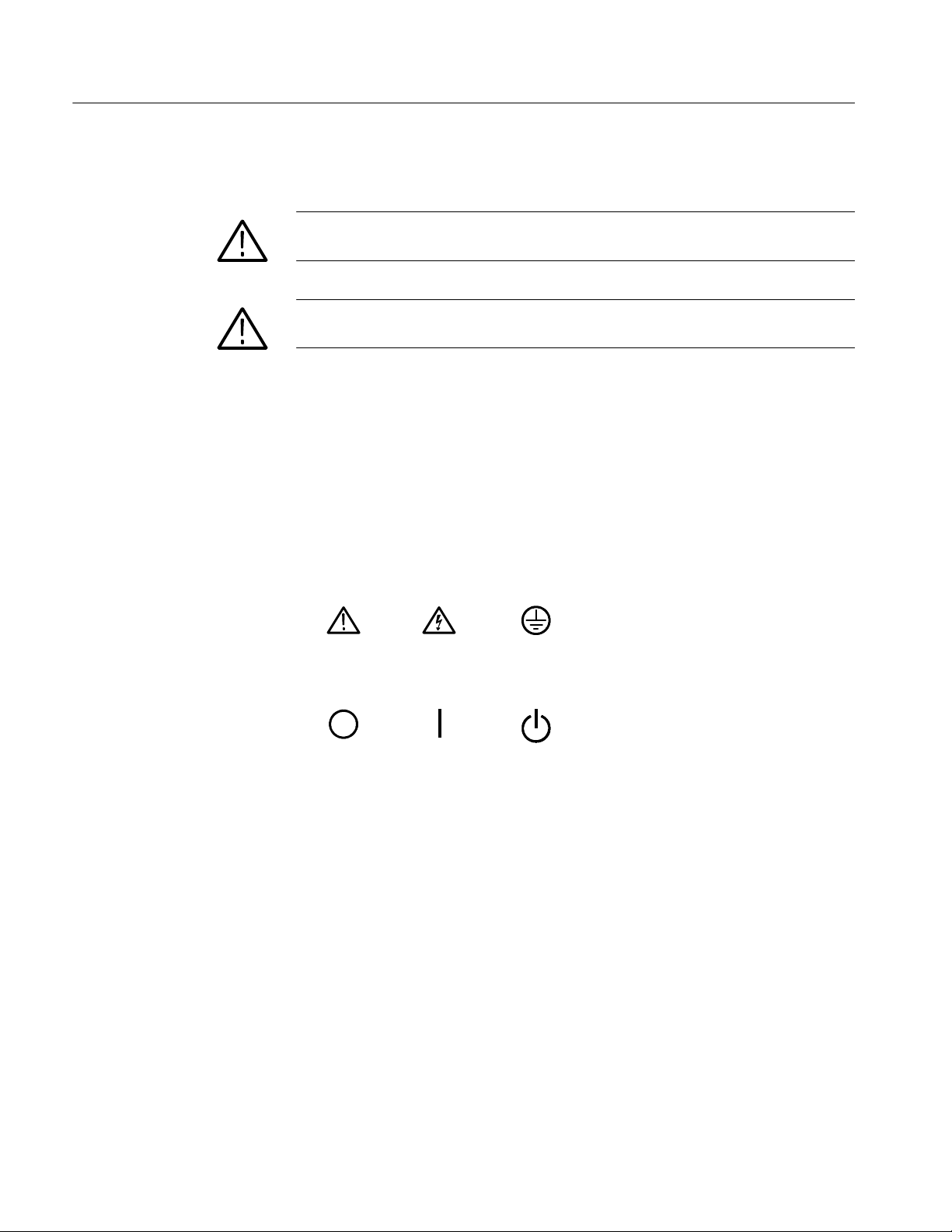
Symbols on the Product. The following symbols may appear on the product:
CAUTION
Refer to Manual
Mains Disconnected
OFF (Power)
WARNING
High Voltage
Mains Connected
ON (Power)
Protective Ground
(Earth) Terminal
Standby
xiv
CSA7000 Series, TDS7000 Series, & TDS6000 Series Instruments User Manual
Page 19

Preface
About This Manual
This user manual covers the following information:
H Describes the capabilities of the instrument, how to install it and how to
reinstall its software
H Explains how to operate the instrument: how to control acquisition of,
processing of, and input/output of information
H Lists specifications and accessories of the instrument
This manual is composed of the following chapters:
H Getting Started shows you how to configure and install your instrument and
provides an incoming inspection procedure.
H Operating Basics uses maps to describe the various interfaces for controlling
the instrument, including the front panel and the software user interface.
These maps provide overviews of the product and its functions from several
viewpoints.
H Reference comprises an encyclopedia of topics (see Overview on page 3--1)
that describe the instrument interface and features, and gives background and
basic information on how to use them. (The online help onboard the
instrument application describes the interface, features, and their usage;
detailed descriptions of all programming commands are found in the
Programmer Online Guide.)
H Appendices provides additional information including the specifications,
measurements, and cleaning information.
CSA7000 Series, TDS7000 Series, & TDS6000 Series Instruments User Manual
xv
Page 20

Preface
Related Manuals and Online Documents
This manual is part of a document set of standard-accessory manuals and online
documentation; this manual mainly focuses on installation, background, and user
information needed to use the product features. See the following list for other
documents supporting instrument operation and service. (Manual part numbers
are listed in Accessories & Options on page 1--37.)
Document name Description
Online Help An online help system, integrated with the User Interface appl ication that ships with this
product. The help is preinstalled in the instrument.
Reference A quick reference to major features of the instrument and how they operate.
Programmer Online Guide An alphabetical listing of the programming commands and other information related to
controlling the instrument over the GPIB
help program and as a PDF manual.
Service Manual Describes how to service the instrument to the module level. This optional manual must
be ordered separately.
Option SM Serial Mask Testing
Option ST Serial Pattern Trigger User Manual
1 Located on the Product Software CD. See CD instructions for installation instructions.
Describes how to use serial mask testing and serial pattern triggers.
1
. This document is available as both an online
For more information on how the product documentation relates to the instrument operating interfaces and features, see Documentation Map on page 2--2.
xvi
CSA7000 Series, TDS7000 Series, & TDS6000 Series Instruments User Manual
Page 21

Contacting Tektronix
Preface
Phone 1-800-833-9200*
Address Tektronix, Inc.
Department or name (if known)
14200 SW Karl Braun Drive
P.O. Box 500
Beaverton, OR 97077
USA
Web site www.tektronix.com
Sales support 1-800-833-9200, select option 1*
Service support 1-800-833-9200, select option 2*
Technical support Email: techsupport@tektronix.com
1-800-833-9200, select option 3*
6:00 a.m. -- 5:00 p.m. Pacific time
* This phone number is toll free in North America. After office hours, please leave a
voice mail message.
Outside North America, contact a Tektronix sales office or distributor; see the
Tektronix web site for a list of offices.
CSA7000 Series, TDS7000 Series, & TDS6000 Series Instruments User Manual
xvii
Page 22

Preface
xviii
CSA7000 Series, TDS7000 Series, & TDS6000 Series Instruments User Manual
Page 23

Product Description
This chapter describes the CSA7000 Series Communications Signal Analyzers,
the TDS7000 Series Digital Phosphor Oscilloscopes, and the TDS6000 Series
Digital Storage Oscilloscopes and their options. Following this description are
three sections:
H Installation shows you how to configure and install the instrument, as well
as how to reinstall the system software included with the product.
H Incoming Inspection provides a procedure for verifying basic operation and
functionality.
H Accessories & Options lists the standard and optional accessories for this
product.
Models
This manual supports the following instruments:
H CSA7404 Communications Signal Analyzer
H CSA7154 Communications Signal Analyzer
H TDS7404 Digital Phosphor Oscilloscope
H TDS7254 Digital Phosphor Oscilloscope
H TDS7154 Digital Phosphor Oscilloscope
H TDS7054 Digital Phosphor Oscilloscope
H TDS7104 Digital Phosphor Oscilloscope
H TDS6604 Digital Storage Oscilloscope
H TDS6404 Digital Storage Oscilloscope
Differences between the instruments will be called out when necessary.
Otherwise, the material applies to all instruments. The word “instrument” refers
to all products.
CSA7000 Series, TDS7000 Series, & TDS6000 Series Instruments User Manual
1- 1
Page 24

Product Description
Key Features
CSA7000 Series, TDS7000 Series, and TDS6000 Series instruments are high
performance solutions for verifying, debugging, and characterizing sophisticated
electronic designs. The series features exceptional signal acquisition performance, operational simplicity, and open connectivity to the design environment.
Classic analog-style controls, a large touch-sensitive display, and graphical
menus provide intuitive control. Open access to the Windows operating system
enables unprecedented customization and extensibility. Key features include:
H Up to 6 GHz bandwidth and 20 GS/s real time sampling rate, depending on
the model
H Record lengths up to 32,000,000 samples, depending on model and option
H Fast acquisition at up to 400,000 acquisitions per second for analog
instrument emulation and isolation of data-dependent failures during
conformance/performance testing and for examination of very low-level
signals in pseudo-random bit streams
H CSA7000 Series: Communication signal analysis, serial mask testing, serial
pattern triggering, and triggering on communications signals. Use of these
features is described in the Option SM Serial Mask Testing and Option ST
Serial Pattern Trigger User Manual
H CSA7000 Series: Optical-to-Electrical converter, optical reference receiver,
and clock recovery provides single-connection convenience, protects
integrity of system calibration, and increases versatility
H Up to 1% DC vertical gain accuracy, depending on the model
H Four input channels (each with 8-bit resolution), CH 3 signal output, and
auxiliary trigger input and output
H Sample, envelope, peak-detect, high-resolution, waveform database, and
average acquisition modes
H Full programmability, with an extensive GPIB-command set and a message-
based interface
1- 2
CSA7000 Series, TDS7000 Series, & TDS6000 Series Instruments User Manual
Page 25

Product Description
H Trigger modes include edge, logic, pulse, serial (CSA7000 Series, optional
on TDS7000 Series and TDS6000 Series, and not available on TDS7104 and
TDS7054), communication (CSA7000 Series and optional on TDS7000
Series and TDS6000 Series), and sequence at up to 4 GHz bandwidth,
depending on the model
H Powerful built-in measurement capability, including histograms, automatic
measurements, eye pattern measurements (CSA7000 Series and optional on
TDS7000 Series and TDS6000 Series), and measurement statistics
H A large 10.4 inch (264.2 mm) color display that supports color grading of
waveform data to show sample density
H MultiView Zoom to view and compare up to four zoom areas at a time. Lock
and manually or automatically scroll up to four zoom areas.
H An intuitive, graphical user interface (UI), with online help that is built in
and available on screen
H Internal, removable disk storage
Product Software
H Wide array of probing solutions
The instrument includes the following software:
H System Software, which includes a specially configured version of
Windows 2000, comes preinstalled on the instrument. Windows 2000 is the
operating system on which the user-interface application of this product runs,
and provides an open desktop for you to install other compatible applications. Do not attempt to substitute any version of Windows that is not
specifically provided by Tektronix for use with your instrument.
H Product Software. Comes preinstalled on the instrument. This software,
running on Windows 2000, is the instrument application. This software starts
automatically when the instrument is powered on, and provides the user
interface (UI) and all other instrument control functions. You can also
minimize the instrument application.
CSA7000 Series, TDS7000 Series, & TDS6000 Series Instruments User Manual
1- 3
Page 26

Product Description
H Support Software. Not preinstalled on the instrument. The compact discs,
included with the instrument, contain additional software and files that may
be useful to you:
H Readme file. This file contains release notes and updates that could not
be included in other product documentation.
H GPIB Programmer Online Help software. This software, in an online
help format, contains the information that you need to program the
instrument through its GPIB interface. A printable PDF file of this
information is also available on the compact disc.
H Performance Verification Procedures. The compact disc contains
instructions to perform a performance verification.
See the instructions for the compact discs for information about installing the
support software.
Occasionally new versions of software for your instrument may become
available at our web site. See Contacting Tektronix on page xvii in Preface.
Software Upgrade
Tektronix may offer software upgrade kits for the instrument. Contact your
Tektronix service representative for more information (see Contacting Tektronix
on page xvii).
1- 4
CSA7000 Series, TDS7000 Series, & TDS6000 Series Instruments User Manual
Page 27

Installation
This chapter covers installation of the instrument, addressing the following
topics:
H Unpacking on page 1--6
H Checking the Environment Requirements on page 1--7
H Connecting Peripherals on page 1--7
H Powering On the Instrument on page 1--9
H Shutting Down the Instrument on page 1--10
H Creating an Emergency Startup Disk on page 1--11
H Backing Up User Files on page 1--11
H Installing Software on page 1--12
H Enabling Your LAN and Connecting to a Network on page 1--15
H Setting up a Dual Display on page 1--17
CAUTION. Be sure to create your emergency startup disk as described on
page 1--11. You may need that disk if you ever need to reinstall Windows 2000
from the instrument hard drive.
CSA7000 Series, TDS7000 Series, & TDS6000 Series Instruments User Manual
1- 5
Page 28

Installation
Unpacking
Verify that you have received all of the parts of your instrument. The graphical
packing list shows the standard accessories that you should find in the shipping
carton (probes depend on the option you ordered.) You should also verify that
you have:
H The correct power cord for your geographical area.
H The compact discs that include copies of the software installed on the
instrument and additional support software that may be useful to you: the
Operating System Restore, Product Software, and Optional Applications
Software. Store the product software in a safe location where you can easily
retrieve it.
NOTE. The certificate of authenticity (Windows 2000 licence agreement) is
attached to the rear of your instrument. This certificate proves your ownership of
the Windows operating system in your instrument. Without this certificate, you
might have to purchase a new Windows license if the hard disk in your instrument ever needs rebuilding or replacement.
H All the standard and optional accessories that you ordered.
Fill out and send in the customer registration card.
1- 6
CSA7000 Series, TDS7000 Series, & TDS6000 Series Instruments User Manual
Page 29
Checking the Environment Requirements
Read this section before attempting any installation procedures. This section
describes site considerations, power requirements, and ground connections for
your instrument.
Installation
Site Considerations
Operating Requirements
Connecting Peripherals
The instrument is designed to operate on a bench or on a cart in the normal
position (on the bottom feet). For proper cooling, at least three inches (7.62 cm)
of clearance is required on both sides of the instrument, and the bottom requires
the clearance provided by the instrument feet.
If you operate the instrument while it is resting on the rear feet, make sure that
you properly route any cables coming out of the rear of the instrument to avoid
damaging them.
CAUTION. To prevent damage to the instrument, keep the bottom and sides of the
instrument clear of obstructions for proper cooling.
The Specifications in Appendix A list the operating requirements for the
instrument. Power source, temperature, humidity, and altitude are listed.
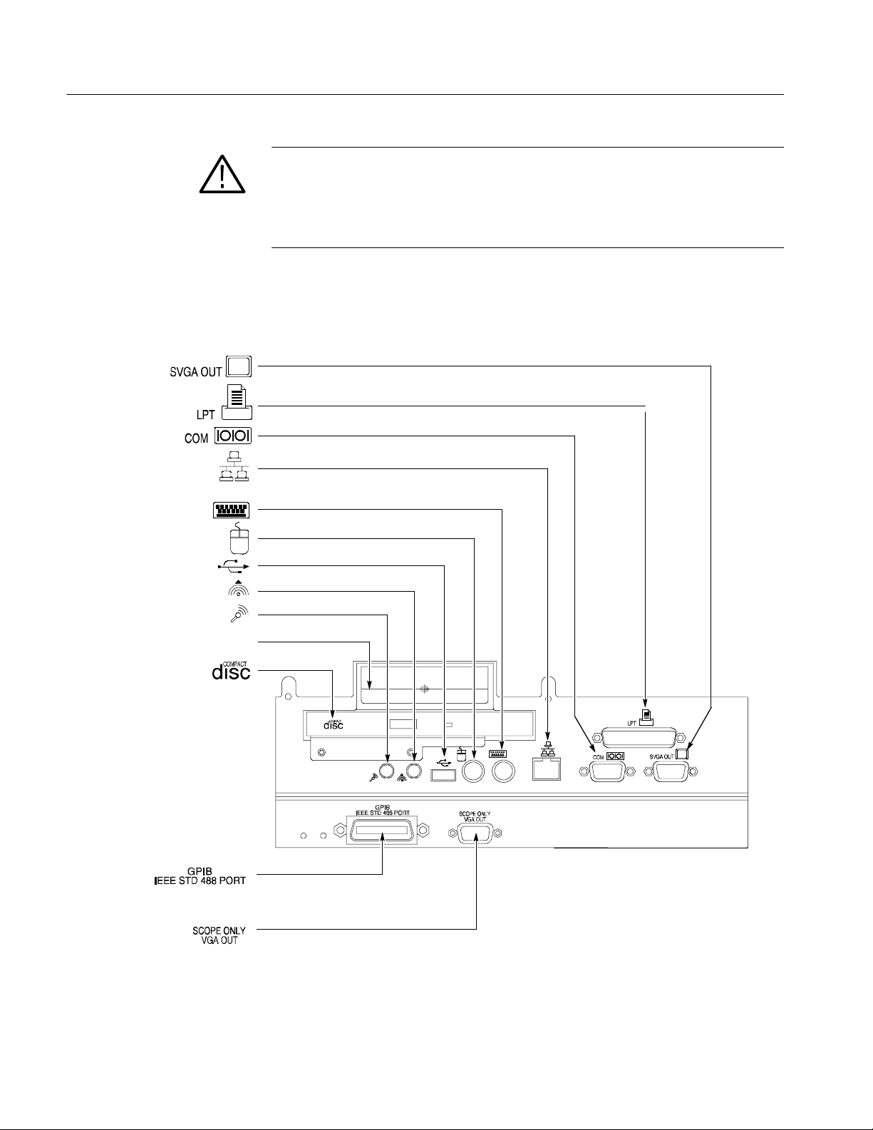
The peripheral connections are the same as those you would make on a personal
computer. The connection points are shown in Figure 1--1. See Table 1--1 on
page 1--9 for additional connection information.
CSA7000 Series, TDS7000 Series, & TDS6000 Series Instruments User Manual
1- 7
Page 30
Installation
CAUTION. To avoid product damage, either power off the instrument or place the
instrument in Standby power mode before installing any accessories except a
USB mouse or keyboard to the instrument connectors. (You can connect and
disconnect USB devices with the power on.) See Shutting Down the Instrument
on page 1--10.
Description Icon/Label Locations
Monitor (PC only, for
dual display
operation) ......
Printer.............
RS-232..........
Network................
Keyboard ................
Mouse.................
USB..................
Audio line out......... ....
Audio line in .............
Removableharddrive...........
Compactdiskdrive.......
GPIB........
Instrument monitor
(large-screen instrument
display)...........
CardSlot......
Figure 1- 1: Locations of peripheral connectors on rear panel
1- 8
CSA7000 Series, TDS7000 Series, & TDS6000 Series Instruments User Manual
Page 31
Installation
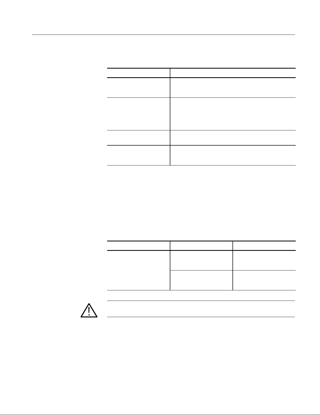
Table 1- 1: Additional accessory connection information
Item Description
Monitor If you use a nonstandard monitor, you may need to change the
Windows 2000 display settings to achieve the proper resolution
for your monitor. To set up a dual display, see page 1--17.
Printer Connect the printer to the EPP (enhanced parallel port)
connector directly. If your printer has a DB-25 connector, use
the adapter cable that came with your printer to connect to the
EPP connector. For information on printer usage, see Printing
Waveforms on page 3--277.
Rackmount Refer to the Rackmount Installation Instructions for information
on installing the rackmount kit.
Other Refer to the Readme file on the Product Software CD for
possible additional accessory installation information not
covered in this manual.
Powering On the Instrument
Follow these steps to power on the instrument for the first time.
Either one of the following fuse sizes can be used, each size requires a different
fuse cap. Both fuses must be the same type. See Table 1--2 and Figure 1--2.
Table 1- 2: Line fuses
Line voltage Description Part number
100 V to 250 V operation UL198G and CSA C22.2, No.
CAUTION. Connect the keyboard, mouse, and other accessories before applying
power to the product.
59, fast acting: 8 A, 250 V
IEC127, sheet 1, fast acting
“F”, high breaking capacity:
6.3 A, 250 V
Tektronix 159-0046-00
Bussman ABC-8
Littelfuse 314008
Tektronix 159-0381-00
Bussman GDA-6.3
Littelfuse 21606.3
CSA7000 Series, TDS7000 Series, & TDS6000 Series Instruments User Manual
1- 9
Page 32

Installation
Rear panel Front panel
3
Turn on
the power.
Check the
fuses.
Figure 1- 2: Powering on the instrument
Shutting Down the Instrument
When you push the front-panel On/Standby switch, the instrument starts a
shutdown process (including a Windows shutdown) to preserve settings and then
removes power from most circuitry in the instrument. Avoid using the rear-panel
power switch or disconnecting the line cord to power off the instrument.
NOTE. If you do not use the On/Standby switch to shut down the instrument
before powering off the instrument, the instrument will be in the factory Default
Setup when powered on the next time.
To completely remove power to the instrument, perform the shutdown just
described, set the power switch on the rear panel to off, and then remove the
power cord from the instrument.
21
Connect the
power cord.
4
If needed, push the On/Standby
switch to power on the instrument.
1- 10
CSA7000 Series, TDS7000 Series, & TDS6000 Series Instruments User Manual
Page 33

Creating an Emergency Startup Disk
Now that you have completed the basic installation process, you should create an
emergency startup disk that you can use to restart your instrument in case of a
major hardware or software failure. Store this disk in a safe place.
CAUTION. Create this disk and store it in a safe place. It may allow you to
recover your Windows 2000 installation without rebuilding the entire instrument
hard disk.
The emergency startup disk contains basic files to restart your instrument. It also
contains files to check and format the hard disk.
Follow these steps to create the emergency startup disk:
1. Minimize the instrument application by selecting Minimize in the File
menu.
2. Click the Windows Start button, point to Programs, Accessories, System
Tools, and click Backup.
Installation
Backing Up User Files
3. On the Tools menu, click Create an Emergency Repair Disk.
4. Insert a floppy disk into the disk drive and follow the on-screen instructions
to create the startup disk.
You should always back up your user files on a regular basis. Use the Back Up
tool to back up files stored on the hard disk. The Back Up tool is located in the
System Tools folder in the Accessories folder.
1. Minimize the instrument application by selecting Minimize in the File
menu.
2. Click the Windows Start button.
3. Select Programs, Accessories, System Tools, Backup in the Start menu.
CSA7000 Series, TDS7000 Series, & TDS6000 Series Instruments User Manual
1- 11
Page 34

Installation
Installing Software
4. Use the backup tool that displays to select your backup media and to select
the files and folders that you want to back up. Use the Windows online help
for information on using the Backup tool. You can back up to the floppy
drive or to a third-party storage device over the printer port (rear panel).
The instrument system and application software is preinstalled at the factory. If
you have to reinstall the software for any reason, refer to the instructions that
accompany the CDs that are shipped with the instrument. If you need to restore
the operating system, you also need the Windows licence information from the
Certificate of Authenticity that is shipped with the instrument.
Software Release Notes
Accessory Software
Read the software release notes README.TXT ASCII file on the product-software CD before performing installation procedures. This file contains additional
installation and operation information that supercedes other product documentation.
To view the README.TXT file, open the Notepad Windows accessory. Then
open the file on the Product Software CD.
The Product Software CD also contains accessory software and files that you can
choose to install in the instrument or in another computer. Refer to the instructions that accompany the CD for installation information.
GPIB Programmer Online Help Software. You can install the GPIB Programmer
online help on the instrument, but it may be more convenient to install it on the
PC that is functioning as the GPIB system controller. From the system controller,
you can copy and paste commands from the help directly into your test programs. The programmer information contains the following content:
H GPIB configuration information for the instrument
H Lists of the command groups and the commands they contain
1- 12
CSA7000 Series, TDS7000 Series, & TDS6000 Series Instruments User Manual
Page 35

Installation
H Detailed command descriptions including syntax and examples
H Status and error messages
H Programming examples
The CD also contains a printable version of the programmer information in the
form of a PDF file.
Semi-Automated Performance Verification Procedure. This software (TDS7104,
TDS7054, and TDS6000 Series Only) provides a semiautomated method to
verify the oscilloscope performance. The installer installs the software and a PDF
file that provides instructions to perform the procedure. The PDF file also lists
the specific test equipment required to perform the procedure.
You should not install this software on the oscilloscope, but rather on the PC you
plan to use as a GPIB controller. The GPIB controller must be equipped with a
National Instruments GPIB Controller card and software.
Manual Performance Verification Procedure. This is a printable PDF file that
describes how to verify the instrument performance using generic test equipment.
User manual. This is a PDF file of this user manual.
Serial Mask User Manual. This is a PDF file that describes how to use the serial
mask features of the instrument.
Optional Accessory Software. The Optional Applications Software CD contains
programs that you can install and run five times per application. You can then
purchase an upgrade from Tektronix if you decide that you want to continue to
use the application. Refer to the instructions that accompany the CD for
installation information.
CSA7000 Series, TDS7000 Series, & TDS6000 Series Instruments User Manual
1- 13
Page 36

Installation
Desktop Applications
You can install desktop application software on the instrument. The instrument
has been tested with the following software products installed:
H Microsoft Office 2000 (including Word, Excel, Powerpoint, and Access)
H MathCad
H MATLAB
Other software products may be compatible but have not been tested by
Tektronix. If the instrument malfunctions after you install software, you should
uninstall the software, and then reinstall the instrument application to restore
proper operation.
Exiting the Instrument Application. Before installing other desktop applications,
you should exit the instrument application. Follow these steps to exit the
instrument application:
NOTE. If you are not using a USB keyboard and mouse, you must power on the
instrument after attaching your keyboard and mouse.
1. Connect a keyboard and mouse to the instrument.
Options
2. While holding down the CTRL and ALT keys, press the DELETE key.
3. Select Task Manager.
4. In the Applications tab, select TekScope.exe, and then select End Process to
stop the instrument application.
The instrument application will restart after you restart the entire system,
following the installation of the desktop application software.
Some options contain software that must be installed and/or enabled. To do the
installation, follow the specific instructions that come with the option.
Tektronix provides a key that you must enter (one time) to enable all the options
that you have purchased for your instrument. To enter the key, select Option
Installation in the Utilities menu, and then follow the on-screen instructions.
1- 14
CSA7000 Series, TDS7000 Series, & TDS6000 Series Instruments User Manual
Page 37

Enabling Your LAN and Connecting to a Network
You can connect the instrument to a network to enable printing, file sharing,
internet access, and other communications functions. Before you make the
connection, do the following steps to enable network access to the instrument:
1
Power
down
Installation
Rear panelFront panel
3
Connect a keyboard
and mouse
2
Power
on
Figure 1- 3: Enabling your LAN and connecting to a network
4. As the instrument begins to boot, press the F2 key on the keyboard
repeatedly until the message “Entering SETUP” (“Loading SETUP” on
some instruments) appears.
CSA7000 Series, TDS7000 Series, & TDS6000 Series Instruments User Manual
1- 15
Page 38

Installation
5. In the BIOS Setup Utility, use the right-arrow key on the keyboard to
highlight the Advanced menu at the top of the screen.
6. Use the arrow down key to highlight PCI Configuration (Peripheral
Configuration on some instruments) in the Advanced screen, and then press
Enter.
7. Use the arrow down key to highlight Embedded Ethernet Controller (LAN
Device on some instruments) in the Peripheral Configuration screen, and
then press Enter.
8. Use the arrow up or down key to highlight Enabled, and then press Enter.
9. Press the F10 key to save and exit. Confirm the Save of Configuration
changes when you are prompted on screen.
10. Use the Windows network setup utility to define the instrument as a network
client and configure it for your network. You can find the network setup
utility in the Windows Start menu if you select Settings > Control Panel
and then double click Network. You should consult your network administrator for specific instructions to make these settings.
NOTE. If you want to disable network access for the instrument, perform the
above procedure except substitute Disabled for the command listed in step 8. The
instrument will boot faster with network access disabled.
1- 16
CSA7000 Series, TDS7000 Series, & TDS6000 Series Instruments User Manual
Page 39

Setting up a Dual Display
Use the following steps to set up the instrument for dual display operation. You
can operate the instrument while having full use of Windows and other applications on the external monitor.
1
Use the On/Standby switch to power down.
2
Connect a
keyboard and
mouse.
3
Connect an
external monitor.
Installation
4
Power on.
Figure 1- 4: Setting up a dual display
CSA7000 Series, TDS7000 Series, & TDS6000 Series Instruments User Manual
5
Power on.
1- 17
Page 40

Installation
6. Watch for a message on the external monitor telling you that Windows has
successfully initialized the display adapter.
7. The instrument should detect that the new monitor was connected. Follow
the instructions on the instrument display to install new drivers for the
monitor.
8. Type a Control-M to minimize the instrument application.
9. In the Windows desktop, right-click the mouse, and then select Properties to
display the Display Properties dialog box.
10. Select the Settings tab, and click the grayed-out monitor in the display box.
11. Click yes when you are prompted to enable the new monitor.
12. Set the resolution that you want to use on the external monitor.
13. Click on the external monitor in the display box, and drag it to the correct
orientation.
CAUTION. Do not change the resolution or color settings for the internal LCD
monitor. The internal resolution must be 640 x 480 and the color setting must be
High Color (24 bit).
14. Click OK to apply the settings. The new monitor will display additional
desktop area.
To make the best use of the new display area, do these additional steps to move
the Windows controls to the external monitor:
1. Click (and hold) on the Windows task bar in the area shown in Figure 1--5,
and then drag it upwards and toward the external monitor. The task bar will
first go to the side of the internal monitor, then to the side of the external
monitor, and finally to the bottom of the external monitor.
1- 18
CSA7000 Series, TDS7000 Series, & TDS6000 Series Instruments User Manual
Page 41

Figure 1- 5: Drag area for Windows task bar
2. Release the mouse when the task bar is where you want it to be.
Installation
Click here to drag task bar.
Select all
3
Internal monitor
Drag
Drop
External monitor
Figure 1- 6: Moving Windows desktop icons to the external monitor
4. If you use the instrument help system, you can drag the help windows to the
external monitor so that you can read them while you operate the instrument.
5. When you open any Windows application, drag the windows from the
application to the external monitor.
CSA7000 Series, TDS7000 Series, & TDS6000 Series Instruments User Manual
1- 19
Page 42

Installation
1- 20
CSA7000 Series, TDS7000 Series, & TDS6000 Series Instruments User Manual
Page 43

Incoming Inspection
This chapter contains instructions for performing the Incoming Inspection
Procedure. This procedure verifies that the instrument is operating correctly after
shipment, but does not check product specifications. This procedure contains the
following parts:
H Self Tests on page 1--22 provides instructions for performing the internal
self tests.
H Functional Tests on page 1--23 measures the time- and amplitude-reference
signals at the PROBE COMPENSATION connector.
H Perform the Extended Diagnostics on page 1--35 provides instructions for
performing internal self calibration and the extended diagnostics.
If the instrument fails any test within this section, it may need service. To contact
Tektronix for service, see Contacting Tektronix on page xvii.
Make sure you have put the instrument into service as detailed in Installation
starting on page 1--5. Then assemble the following test equipment and proceed
with the procedures that follow.
Assemble Equipment
Self tests do not require any test equipment. The functional tests require the
following test equipment:
H One BNC cable, such as Tektronix part number 012-0076-xx
H One1.44Mbyte,3.5inchformatteddisktocheckthefilesystem
The functional tests for the CSA7000 Series, TDS6000 Series, TDS7404,
TDS7254, and TDS7154 instrument require the following additional test
equipment:
H A P7240 probe (P7260 probe with TDS6604)
H A probe calibration and deskew fixture, Tektronix part number 067-0405-xx
(067-0848-xx for TDS6604)
CSA7000 Series, TDS7000 Series, & TDS6000 Series Instruments User Manual
1- 21
Page 44

Incoming Inspection
Self Tests
H One TCA-BNC TekConnect adapter, or one TCA-SMA TekConnect adapter
and one SMA male-to-BNC female adapter, such as Tektronix part number
015-1018-xx
This procedure uses internal routines to verify that the instrument functions and
was adjusted properly. No test equipment or hookups are required.
Equipment
required
Prerequisites Power on the instrument and allow a 20 minute warm-up before doing
1. Verify that internal diagnostics pass: Do the following substeps to verify
passing of internal diagnostics.
a. Display the System diagnostics menu:
H If the instrument is in tool-bar mode, click the MENU button to put
the instrument into menu bar mode.
H From the Utilities menu, select Instrument Diagnostics . . . . This
displays the diagnostics control window.
b. Run the System Diagnostics:
H First disconnect any input signals and probes from all four channels.
H Click the Run button in the diagnostics control window.
c. Wait: The internal diagnostics do an exhaustive verification of proper
instrument function. This verification will take five to fifteen minutes.
When the verification is finished, the resulting status will appear in the
diagnostics control window.
None
this procedure.
1- 22
d. Verify that no failures are found and reported on-screen. All tests should
pass.
CSA7000 Series, TDS7000 Series, & TDS6000 Series Instruments User Manual
Page 45

Functional Tests
Incoming Inspection
e. Run the signal-path compensation routine:
H From the Utilities menu, select Instrument Calibration . . . . This
displays the instrument calibration control window.
H If required because the instrument is in service mode, select the
Signal Path button under Calibration Area.
H Touch the Calibrate button to start the routine.
f. Wait: Signal-path compensation may take five to ten minutes to run.
g. Confirm signal-path compensation returns passed status: Verify that the
word Pass appears in the instrument calibration control window.
2. Return to regular service: C lick the Close button to exit the instrument
calibration control window.
The purpose of these procedures is to confirm that the instrument functions
properly. A list of required test equipment is shown on page 1--21.
NOTE. These procedures verify that the instrument features operate. They do not
verify that they operate within limits.
Therefore, when the instructions in the functional tests that follow call for you to
verify that a signal appears on-screen “that is about five divisions in amplitude”
or “has a period of about six horizontal divisions,” and so forth, do not
interpret the quantities given as limits.
CSA7000 Series, TDS7000 Series, & TDS6000 Series Instruments User Manual
1- 23
Page 46

Incoming Inspection
NOTE. Do not make changes to the front-panel settings that are not called out in
the procedures. Each verification procedure will require you to set the instrument
to certain default settings before verifying functions. If you make changes to
these settings, other than those called out in the procedure, you may obtain
invalid results. In this case, redo the procedure from step 1.
When you are instructed to push a front-panel button or screen button, the button
may already be selected (its label will be highlighted). If this is the case, it is not
necessary to push the button.
Check Vertical Operation
Equipment
required
Prerequisites None
One BNC cable
CSA7404, CSA7154, TDS7404, TDS7254, TDS7154, TDS6604, &
TDS6404:
One P7240 probe (P7260 probe for TDS6604)
One probe calibration and deskew fixture
1. Initialize the instrument: Push the front-panel DEFAULT SETUP button.
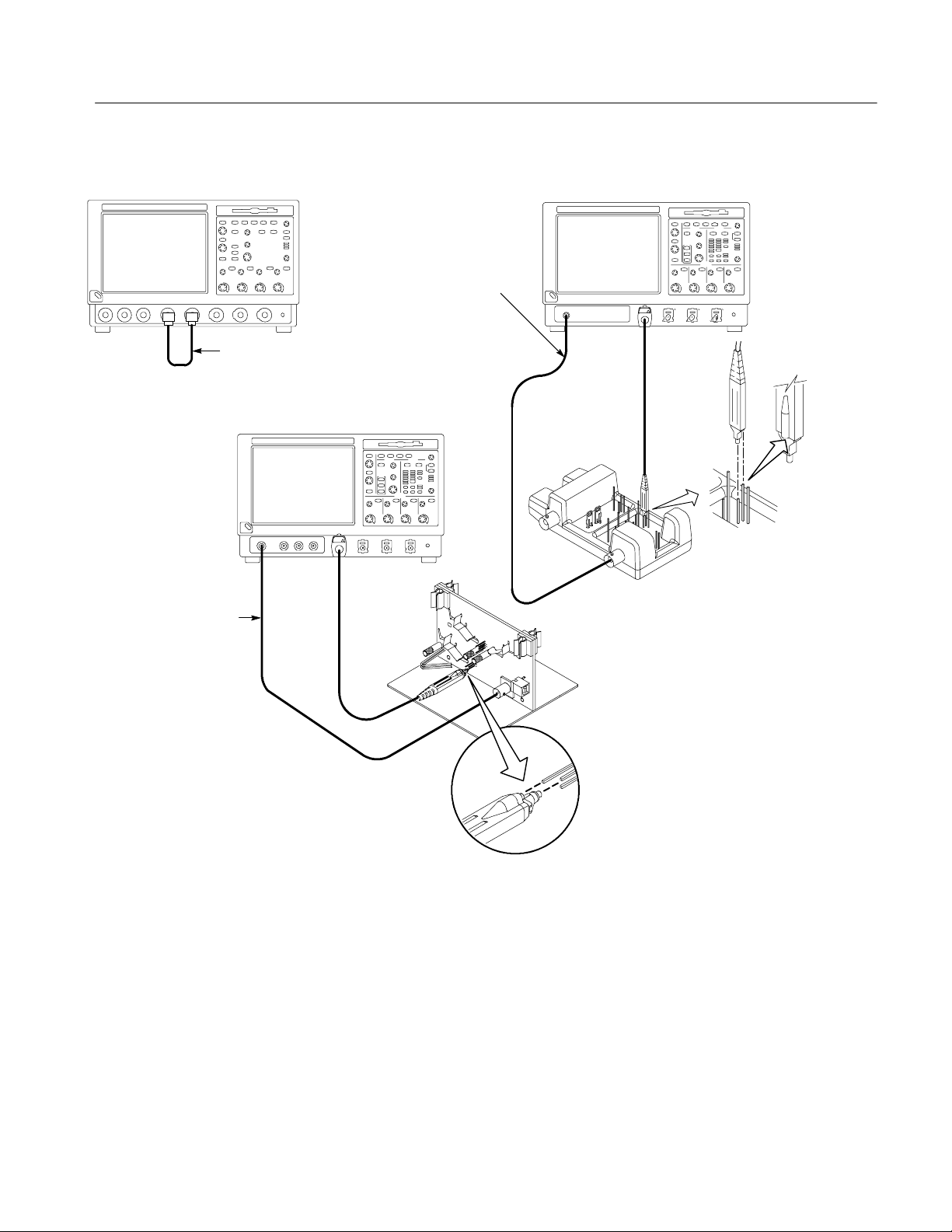
2. Hook up the signal source: Connect the equipment as shown in Figure 1--7
to the channel input you want to test (beginning with CH 1).
3. Turn off all channels: If any of the front-panel channel buttons are lighted,
push those buttons to turn off the displayed channels. See Figure 1--8.
4. Select the channel to test: Push the channel button for the channel you are
currently testing. The button lights and the channel display comes on.
1- 24
CSA7000 Series, TDS7000 Series, & TDS6000 Series Instruments User Manual
Page 47
Incoming Inspection
TDS7104 & TDS7054
BNC cable from the
PROBE COMPENSATION
output to the GAIN CAL
SIG input on the fixture.
BNC cable from PROBE
COMPENSATION output
to channel input
TDS6604
BNC cable from PROBE
COMPENSATION output to
the A input of the Probe
Calibration and Deskew
Fixture
CSA7404, CSA7154, TDS7404,
TDS7254, TDS7154, & TDS6404
A
Remove
the jumper
Connect the probe tip to
the short pin and the
probe ground to the long
pin as shown.
NOTE. If a P7240 probe is
not available, connect the
probe compensation output
to the channel input using a
BNC cable and adapters.
GAIN CAL connections
Figure 1- 7: Universal test hookup for functional tests - CH 1 shown
CSA7000 Series, TDS7000 Series, & TDS6000 Series Instruments User Manual
1- 25
Page 48

Incoming Inspection
TDS
&
Channel buttons
Figure 1- 8: Channel button location
5. Set up the instrument:
H Push the front-panel AUTOSET button. This sets the horizontal and
vertical scale and vertical offset for a usable display and sets the trigger
source to the channel that you are testing.
H Touch the Vert button and then touch Offset. Confirm that the Ch1
Offset is 1.8 V (0.0 V if not using a probe).
6. Verify that the channel is operational: Confirm that the following statements
are true.
H Verify that the vertical scale readout and the waveform amplitude for the
channel under test are as shown in Table 1--3.
Table 1- 3: Vertical settings
CSA7404, CSA7154, TDS7404, TDS7254,
TDS7154, TDS6604, & TDS6404
Setting
Scale 100 mV 500 mV 500 mV
Waveform amplitude 4 divisions 0.5 divisions 2 divisions
With P7240 or P7260
Without P7240
7104
TDS7054
1- 26
CSA7000 Series, TDS7000 Series, & TDS6000 Series Instruments User Manual
Page 49

Incoming Inspection
H The front-panel vertical POSITION knob (for the channel you are
testing) moves the signal up and down the screen when rotated.
H Turning the vertical SCALE knob counterclockwise (for the channel you
are testing) decreases the amplitude of the waveform on-screen, turning
the knob clockwise increases the amplitude, and returning the knob to
the original scale setting returns the amplitude to that shown in
Table 1--3 for that scale setting.
7. Verify that the channel acquires in all acquisition modes: From the
Horiz/Acq menu, select Horizontal/Acquisition Setup . . . . Click the
Acquisition tab in the control window that displays. Click each of the
acquisition modes and confirm that the following statements are true (see
Using the Acquisition Controls on page 3--28 for more information):
H Sample mode displays an actively acquiring waveform on-screen. (Note
that there is a small amount of noise present on the square wave).
H Peak Detect mode displays an actively acquiring waveform on-screen
with the noise present in Sample mode “peak detected.”
H Hi Res mode displays an actively acquiring waveform on-screen with the
noise that was present in Sample mode reduced.
H Average mode displays an actively acquiring waveform on-screen with
the noise reduced.
H Envelope mode displays an actively acquiring waveform on-screen with
the noise displayed.
H Waveform Database mode displays an actively acquiring waveform
on-screen that is the accumulation of several acquisitions.
8. Test all channels: Repeat steps 2 through 7 until all four input channels are
verified.
9. Remove the test hookup: Disconnect the equipment from the channel input
and the probe compensation output.
CSA7000 Series, TDS7000 Series, & TDS6000 Series Instruments User Manual
1- 27
Page 50

Incoming Inspection
Check Horizontal
Operation
Equipment
required
Prerequisites None
One BNC cable
CSA7404, CSA7154, TDS7404, TDS7254, TDS7154, TDS6604, &
TDS6404:
One TekConnect adapter
1. Initialize the instrument:Push the front-panel DEFAULT SETUP button.
2. Hook up the signal source: Connect the equipment to the CH 1 input as
shown in Figure 1--9.
TDS7104 & TDS7054
BNC cable from PROBE
COMPENSATION
output to CH 1 input
CSA7404, CSA7154, TDS7404, TDS7254,
TDS7154, TDS6604, & TDS6404
BNC cable from PROBE
COMPENSATION output
to CH 1 input
Figure 1- 9: Setup for time base test
3. Set up the instrument: Push the front-panel AUTOSET button.
4. CSA7404, CSA7154, TDS7404, TDS7254, TDS7154, TDS6604, &
TDS6404:
Touch the Vert button and then touch Offset. Adjust the Ch1 Offset to 0.8 V
using the multipurpose knob.
5. CSA7404, CSA7154, TDS7404, TDS7254, TDS7154, TDS6604, &
TDS6404:
Set the Vertical SCALE to 100 mV per division.
6. Set the time base: Set the horizontal SCALE to 200 s/div. The time-base
readout is displayed at the bottom of the graticule.
1- 28
CSA7000 Series, TDS7000 Series, & TDS6000 Series Instruments User Manual
Page 51

Incoming Inspection
7. Verify that the time base operates: Confirm the following statements.
H One period of the square-wave probe-compensation signal is about five
horizontal divisions on-screen for the 200 s/div horizontal scale setting.
H Rotating the horizontal SCALE knob clockwise expands the waveform
on-screen (more horizontal divisions per waveform period), counterclockwise rotation contracts it, and returning the horizontal scale to
200 s/div returns the period to about five divisions.
H The horizontal POSITION knob positions the signal left and right
on-screen when rotated.
8. Verify horizontal delay:
a. Center a rising edge on screen:
H Set the horizontal POSITION knob so that the rising edge where the
waveform is triggered is lined up with the center horizontal
graticule.
H Change the horizontal SCALE to 20 s/div. The rising edge of the
waveform should remain near the center graticule and the falling
edge should be off screen.
b. Turn on and set horizontal delay:
H From the Horiz/Acq menu, select Horizontal/Acquisition
Setup....
H Click the Horizontal tab in the control window that displays.
H Click the Delay Mode button to turn delay on.
H Double click the Horiz Delay control in the control window to
display the pop-up keypad. Click the keypad buttons to set the
horizontal delay to 500 s, and then click the ENTER key.
c. Verify the waveform: Verify that a falling edge of the waveform is within
a few divisions of center screen.
CSA7000 Series, TDS7000 Series, & TDS6000 Series Instruments User Manual
1- 29
Page 52

Incoming Inspection
d. Adjust the horizontal delay: Rotate the upper multipurpose knob to
change the horizontal delay setting. Verify that the falling edge shifts
horizontally. Rotate the front-panel horizontal POSITION knob. Verify
that this knob has the same effect (it also adjusts delay, but only when
delay mode is on).
e. Verify the delay toggle function:
H Rotate the front-panel horizontal POSITION knob to center the
falling edge horizontally on the screen.
H Change the horizontal SCALE to 40 ns/div. The falling edge of the
waveform should remain near the center graticule. If not, readjust the
delay setting to center the falling edge.
H Push the front-panel DELAY button several times to toggle delay off
and on and back off again. Verify that the display switches quickly
between two different points in time (the rising and falling edges of
this signal).
Check Trigger Operation
9. Remove the test hookup: Disconnect the equipment from the channel input
and the probe compensation output.
Equipment
required
Prerequisites None
One BNC cable
CSA7404, CSA7154, TDS7404, TDS7254, TDS7154
TDS6404
One TCA-BNC TekConnect adapter
, TDS6604, &
1. Initialize the instrument: Push the front-panel DEFAULT SETUP button.
2. Hook up the signal source: Connect the equipment to the CH 1 input as
shown in Figure 1--10.
3. Set up the instrument: Push the front-panel AUTOSET button.
1- 30
CSA7000 Series, TDS7000 Series, & TDS6000 Series Instruments User Manual
Page 53

Incoming Inspection
TDS7104 & TDS7054
BNC cable from PROBE
COMPENSATION
output to CH 1 input
CSA7404, CSA7154, TDS7404, TDS7254,
TDS7154, TDS6604, & TDS6404
BNC cable from PROBE
COMPENSATION output
to CH 1 input
Figure 1- 10: Setup for trigger test
4. CSA7404, CSA7154, TDS7404, TDS7254, TDS7154, TDS6604, &
TDS6404:
Touch the Vert button and then touch Offset. Adjust the Ch1 Offset to 0.8 V
using the multipurpose knob.
5. CSA7404, CSA7154, TDS7404, TDS7254, TDS7154, TDS6604, &
TDS6404:
Set the Vertical SCALE to 100 mV per division.
6. Verify that the main trigger system operates: Confirm that the following
statements are true.
H The trigger level readout for the A (main) trigger system changes with
the trigger-LEVEL knob.
H The trigger-LEVEL knob can trigger and untrigger the square-wave
signal as you rotate it. (Leave the signal untriggered).
H Pushing the front-panel trigger LEVEL knob sets the trigger level to the
50% amplitude point of the signal and triggers the signal that you just
left untriggered. (Leave the signal triggered.)
CSA7000 Series, TDS7000 Series, & TDS6000 Series Instruments User Manual
1- 31
Page 54

Incoming Inspection
7. Verify that the delayed trigger system operates:
a. Set up the delayed trigger:
H From the Trig menu, select A→B Sequence . . . . This displays the
A→B Sequence tab of the trigger setup control window.
H Click the Trig After Time button under A Then B.
H Click the B Trig Level control in the control window.
b. Confirm that the following statements are true:
H The trigger-level readout for the B trigger system changes as you
turn the lower multipurpose knob.
H As you rotate the lower multipurpose knob, the square-wave
probe-compensation signal can become triggered and untriggered.
(Leave the signal triggered.)
c. Verify the delayed trigger counter:
Check File System
H Double click the Trig Delay control to pop up a numeric keypad for
that control.
H Click on the keypad to enter a trigger delay time of 1 second,and
then click Enter.
H Verify that the trigger READY indicator on the front panel flashes
about once every second as the waveform is updated on-screen.
8. Remove the test hookup: Disconnect the equipment from the channel input
and the Probe Compensation output.
Equipment
required
Prerequisites None
One BNC cable
One 1.44 Mbyte, 3.5 inch DOS-compatible formatted disk.
CSA7404, CSA7154, TDS7404, TDS7254, TDS7154, TDS6604, &
TDS6404:
One TCA-BNC TekConnect adapter
1- 32
CSA7000 Series, TDS7000 Series, & TDS6000 Series Instruments User Manual
Page 55

Incoming Inspection
1. Initialize the instrument: Push the front-panel DEFAULT SETUP button.
2. Hook up the signal source: Connect the equipment to the CH 1 input as
shown in Figure 1--11.
TDS7104 & TDS7054
BNC cable from PROBE
COMPENSATION
output to CH 1 input
CSA7404, CSA7154, TDS7404, TDS7254,
TDS7154, TDS6604, & TDS6404
BNC cable from PROBE
COMPENSATION output
to CH 1 input
Figure 1- 11: Setup for the file system test
3. Insert the test disk: Insert the floppy disk in the floppy disk drive at the top
of the front panel.
4. Set up the instrument: Push the front-panel AUTOSET button.
5. CSA7404, CSA7154, TDS7404, TDS7254, TDS7154, TDS6604, &
TDS6404:
Touch the Vert button and then touch Offset. Adjust the Ch1 Offset to 0.8 V
using the multipurpose knob.
6. CSA7404, CSA7154, TDS7404, TDS7254, TDS7154, TDS6604, &
TDS6404:
Set the Vertical SCALE to 100 mV per division.
7. Set the time base: Set the horizontal SCALE to 1ms/div. The time-base
readout is displayed at the bottom of the graticule.
8. Save the settings:
a. Pull down the File menu to select Instrument Setup . . . . This displays
the instrument setups control window.
CSA7000 Series, TDS7000 Series, & TDS6000 Series Instruments User Manual
1- 33
Page 56

Incoming Inspection
b. Click the Save button under Save settings to file in the control window.
This displays a familiar Windows dialog box for choosing a destination
directory naming the file.
c. In the Save Instrument Setup As dialog box, select the 3
1
/2Floppy (A:)
icon in the Save in: drop-down list to set the save destination to the
floppy disk.
d. Note the default file name, and then click the Save buttontosavethe
setup to the default file name.
9. Change the settings again: Set the horizontal SCALE to 200 s/div.
10. Verify the file system works:
a. Click the Recall Setups tab in the control window.
b. Click the Recall button under Recall settings from file in the control
window. This displays a familiar Windows dialog box for locating the
settings file that you want to recall.
1
c. In the Recall Instrument Setup dialog box, select the 3
/2Floppy (A:)
icon in the Look in: drop-down list.
d. Locate and double click in the dialog box on the setup file that you
previously stored.
e. Verify that the instrument retrieved the saved setup from the disk. Do
this by noticing the horizontal SCALE is again 1 ms and the waveform
shows ten cycles just as it did when you saved the setup.
1- 34
11. Remove the test hookup:
a. Disconnect the equipment from the channel input and the probe
compensation output.
b. Remove the floppy disk from the floppy disk drive.
CSA7000 Series, TDS7000 Series, & TDS6000 Series Instruments User Manual
Page 57

Perform the Extended Diagnostics
Extended diagnostics and self calibration perform a more detailed functionality
check than the incoming inspection and Power-on diagnostics.
NOTE. Allow a 20-minute warm-up before running the self calibration.
Disconnect any attached probes from the instrument. Then select the Utilities
menu. Run the self calibration followed by the extended diagnostics by first
selecting the Instrument Calibration (see page 3-- 171 for additional information
on signal path compensation) and then the Instrument Diagnostics tabs. Results
of the tests display on their property pages.
Incoming Inspection
Checking the Underlying
System (Optional)
To check the hardware and Windows software underlying the instrument UI (user
interface), run the CheckIt Utilities from the Windows Start menu:
1. Exit the instrument application before running the external diagnostics.
a. Display the Task Manager by pressing CTRL, ALT,andDelete,and
then touch Task Manager.
b. Select TekScope and then touch End Task.
2. Click Start, then click Programs in the Start Menu. Finally, click CheckIt
Utilities.
3. From the Go To menu, select and run the tests you want to perform.
4. Check test results. All tests except the Modem and CD-ROM tests should
pass. The CD-ROM test requires data from the CheckIt Utilities CD.
5. Dismiss the CheckIt Utilities: Select Exit in the File menu.
6. Restart your instrument UI software: Click Start, then click Programs in the
Start Menu. Finally, click Tektronix Oscilloscope and then TekScope.
CSA7000 Series, TDS7000 Series, & TDS6000 Series Instruments User Manual
1- 35
Page 58

Incoming Inspection
1- 36
CSA7000 Series, TDS7000 Series, & TDS6000 Series Instruments User Manual
Page 59
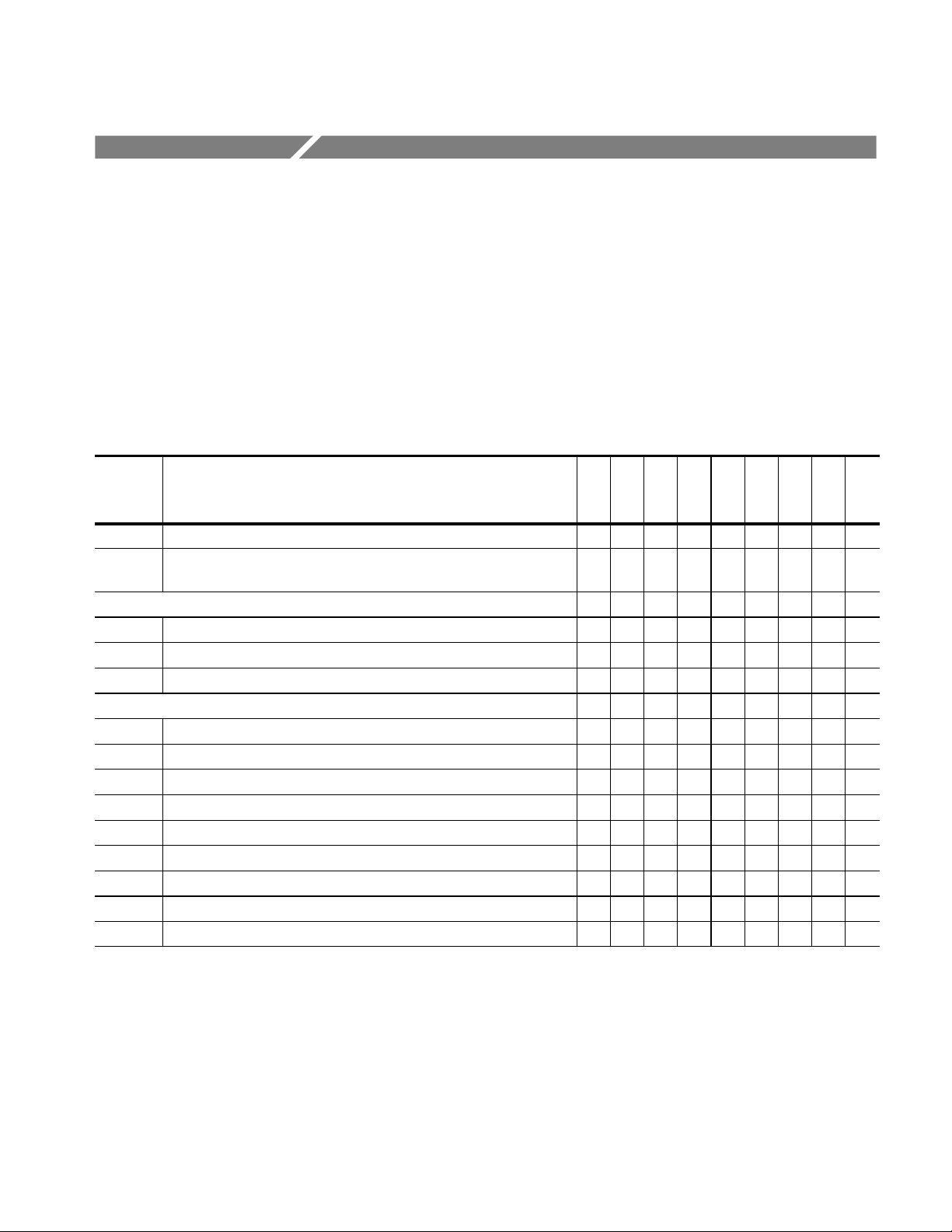
Accessories & Options
This section lists the standard and optional accessories available for the
instrument, as well as the product options.
Options
The following options can be ordered for the instrument:
Table 1- 4: Options
CSA7154
CSA7404
Option Description
1K K4000 Instrument Cart n n n n n n n n n
1R Rack Mount Kit (includes: hardware and instructions for converting to
rackmount configuration)
Acquisition memory
2M Long record length: 2 Ms per channel, 8 Ms maximum n n n n n n n
3M Long record length: 4 Ms per channel, 16 Ms maximum n n n n n n n
4M Long record length: 8 M per channel, 32 Ms maximum n n n n n
Probes
30 No probes n n
33 Add one P6158, 3 GHz, low capacitance, 20x divider probe n n
34 Add one P6247, 1 GHz differential probe n n
35 Add one P6243, 1 GHz active probe n n
36 Add one P6139A, 500 MHz passive probe n n
37 Add one P6245, 1 GHz Active Probe n n n n
39 Add one P6248, 1.7 GHz Differential Probe n n n n
51 Add one P7240, 4 GHz, active probe n n n
52 Add one P7330, 3 GHz, differential probe n n n n n
n n n n n n n n n
TDS7404
TDS7154
TDS7254
TDS7104
TDS7054
TDS6604
TDS6404
CSA7000 Series, TDS7000 Series, & TDS6000 Series Instruments User Manual
1- 37
Page 60

Accessories & Options
Table 1- 4: Options (Cont.)
CSA7154
CSA7404
TDS7254
TDS7404
TDS7154
TDS7104
TDS6604
TDS7054
TDS6404
Option
Power cords
A1 Universal European 230 V, 50 Hz power cord n n n n n n n n n
A2 United Kingdom 230 V, 50 Hz power cord n n n n n n n n n
A3 Australian 230 V, 50 Hz power cord n n n n n n n n n
A5 Switzerland 230 V, 50 Hz power cord n n n n n n n n n
AC China 230 V, 50 Hz power cord n n n n n n n n n
A99 No power cord n n n n n n n n n
Software applications
J1 TDSJIT2 Jitter Analysis application n n n n n n n n n
J2 TDSDDM2 Disk Drive Measurements application n n n n n n n
JT3 TDSJIT3 Advanced Jitter Analysis application with random and
CP2 TDSCPM2 Compliance Testing for ITU-T G.703 and ANSI T1.102
USB USB2 Compliance Testing Software for USB1.0/USB2.0 standards
SM Serial Communications Mask Testing (Standard on CSA7000 Series) n n n n n n n
ST Serial Pattern Triggering (Standard on CSA7000 Series) n n n n n n n
TC1 Add (1) TCA--1MEG TekConnect high--impedance buffer amplifier n n n
Field upgrades
CSA7UP Many are available. Contact Tektronix (see page xvii) for a complete
TDS7UP Many are available. Contact Tektronix (see page xvii) for a complete
TDS6UP Many are available. Contact Tektronix (see page xvii) for a complete
Description
n n n n n n n n n
deterministic jitter analysis
n n n n n n n
communications standards (Requires Option SM)
n n n n n n n n n
(requires TDSUSBF USB test fixture)
n n
list of available CSA7UP options
n n n n n
list of available TDS7UP options
n n
list of available TDS6UP options
1- 38
CSA7000 Series, TDS7000 Series, & TDS6000 Series Instruments User Manual
Page 61

Table 1- 4: Options (Cont.)
CSA7154
CSA7404
TDS7254
TDS7404
Accessories & Options
TDS7154
TDS7104
TDS6604
TDS7054
TDS6404
Option
Service offerings
C3 Calibration services extended to cover three years n n n n n n n n n
C5 Calibration services extended to cover five years n n n n n n n n n
D1 Calibration data report n n n n n n n n n
D3 Test Data for calibration services in Opt. C3 n n n n n n n n n
D5 Test Data for calibration services in Opt. C5 n n n n n n n n n
R3 Repair warranty extended to cover three years n n n n n n n n n
R5 Repair warranty extended to cover five years n n n n n n n n n
Description
Accessories
This section lists the standard and optional accessories available for this
instrument.
Standard
The following accessories are shipped with the instrument:
Table 1- 5: Standard accessories
Accessory Part number
Graphical Packing List
CSA7404 & CSA7154
TDS7404, TDS7254, & TDS7154
TDS7104 & TDS7054
TDS6604 & TDS6404
User Manual 071-7010-xx
Reference Kit 020-2404-xx
CSA7000 Series, TDS7000 Series, & TDS6000 Series Instruments User Manual
071-1045-xx
071-0890-xx
071-0710-xx
071-1061-xx
1- 39
Page 62

Accessories & Options
p
,
/pp()
Table 1- 5: Standard accessories (Cont.)
Accessory Part number
Product Software CD
CSA7404, CSA7154, TDS7404, TDS7254, & TDS7154
TDS7104 & TDS7054
TDS6604 & TDS6404
Operating System Restore CD 020-2498-xx
Optional Applications Software CD and Documentation Kit 020-2450-xx
Oscilloscope Analysis and Connectivity Made Easy Kit 020-2449--xx
Option SM and ST User Manual 071-1035-xx
Online Help (part of the application software) ——
Performance Verification (a pdf file on the Product Software CD) ——
Programmer Online Guide (files on the Product Software CD) ——
NIST, Z540-1, and ISO9000 Calibration Certificate ——
063-3461-xx
063-3376-xx
063-3541-xx
Four TekConnect-to-SMA adapters, CSA7404, TDS7404, TDS6604, &
TDS6404
Four TekConnect-to-BNC adapters, CSA7154, TDS7254, &
TCA-SMA
TCA-BNC
TDS7154
Adapters, CSA7404 & CSA7154 020-2423-xx
O/E Electrical Out-to-CH1 Input adapter (013-0327-xx)
O/E-to-SMA adapter (013-0326-xx)
U.S. Power Cord 161-0104-00
Mouse 119-6298-xx
Front Cover
CSA7404, CSA7154, TDS7404, TDS7254, TDS7154,
TDS6604, & TDS6404
TDS7104 TDS7054
Accessory Pouch 016-1441-xx
200-4653-xx
200-4519-xx
1- 40
CSA7000 Series, TDS7000 Series, & TDS6000 Series Instruments User Manual
Page 63
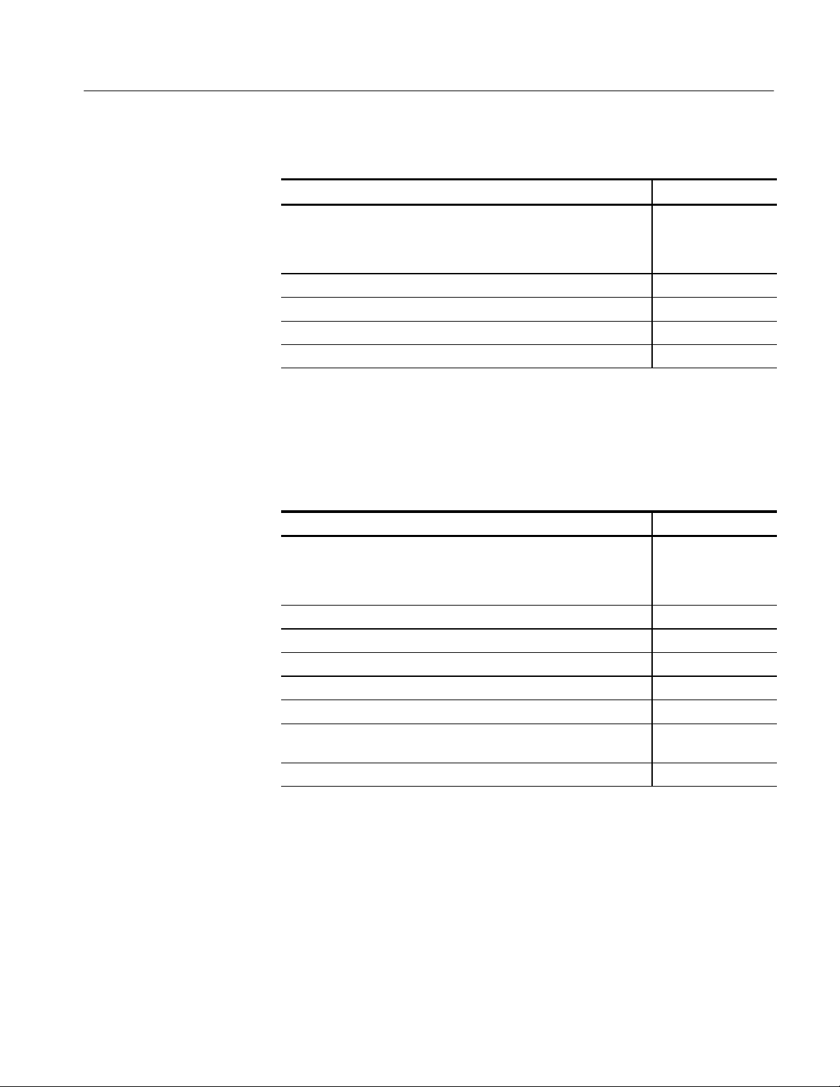
Accessories & Options
Table 1- 5: Standard accessories (Cont.)
Accessory Part number
Probe Calibration and Deskew Fixture, with instructions
CSA7404, CSA7154, TDS7404, TDS7254, TDS7154,
TDS7104 TDS7054 & TDS6404
TDS6604
Four P6139A Probes (with TDS7054 only) P6139A
Fiber cleaning kit, CSA7404 & CSA7154 020-2357-xx
FC/PC UCI adapter, installed, CSA7404 & CSA7154 119-4516-xx
Click’N Burn Software CD 063-3575-xx
067-0405-xx
067-0484-xx
Optional
The accessories in Table 1--6 are orderable for use with the instrument at the time
this manual was originally published. Consult a current Tektronix catalog for
additions, changes, and details.
Table 1- 6: Optional accessories
Accessory Part number
Service Manual
CSA7404, CSA7154, TDS7404, TDS7254, & TDS7154
TDS7104 & TDS7054
TDS6604 & TDS6404
Transit Case 016-1522-xx
Scope Cart K4000 (Option 1K)
P6158 20x 1 kΩ low capacitance voltage divider probe
P6245 1.5 GHz high speed active probe
P6248 1.5 GHz differential probe
P7240 active 4 GHz probe, CSA7404, CSA7154, TDS7404, TDS7254,
TDS7154, TDS6604 & TDS6404
P7260 active 6 GHz probe, TDS6604 & TDS6404 P7260
1
1
1
071-7011-xx
071-0711-xx
071-7021-xx
P6158
P6245
P6248
P7240
CSA7000 Series, TDS7000 Series, & TDS6000 Series Instruments User Manual
1- 41
Page 64

Accessories & Options
Table 1- 6: Optional accessories (Cont.)
Accessory Part number
P7330 differential 3.5 GHz probe, CSA7404, CSA7154, TDS7404,
TDS7254, TDS7154, TDS6604 & TDS6404
P6139A 500 MHz passive 10x probe
P6243 1 GHz high speed active probe
P6246 400 MHz differential probe
P6247 1 GHz differential probe
P6249 4 GHz differential probe
P6330 differential 3 GHz probe
TCP202 DC to 50 MHz current probe
P5205 high voltage differential probe
P5210 high voltage differential probe
P6015A high voltage probe
1
ADA400A differential preamplifier
CT6 high frequency current probe
AM503S DC/AC current measurement system
1
1
1
1
1
1
1
1
1
1
1
1
P7330
P6139A
P6243
P6246
P6247
P6249
P6330
TCP202
P5205
P5210
P6015A
ADA400A
CT6
AM503S
P7260 6 GHz 5X/25X active probe, CSA7404, CSA7154, TDS7404,
P7260
TDS7254, TDS7154, TDS6604 & TDS6404
P6150 9 GHz/3 GHz low capacitance divider probe
P6701B optical/electrical converter (500 to 950 nm)
P6703B optical/electrical converter (1100 to 1650 nm)
AFTDS Telecomm differential electrical interface adapter (for line rates
<8 Mb/s; requires TCA--BNC adapter)
1
1
1
1
P6150
P6701A/B
P6703A/B
AFTDS
TDSUSBF USB test fixture; used with Option USB TDSUBF
AMT75 1 GHz 75-ohm adapter
TekConnect-to-SMA adapter, CSA7404, CSA7154, TDS7404,
1
AMT75
TCA-SMA
TDS7254, TDS7154, TDS6604 & TDS6404
1- 42
CSA7000 Series, TDS7000 Series, & TDS6000 Series Instruments User Manual
Page 65
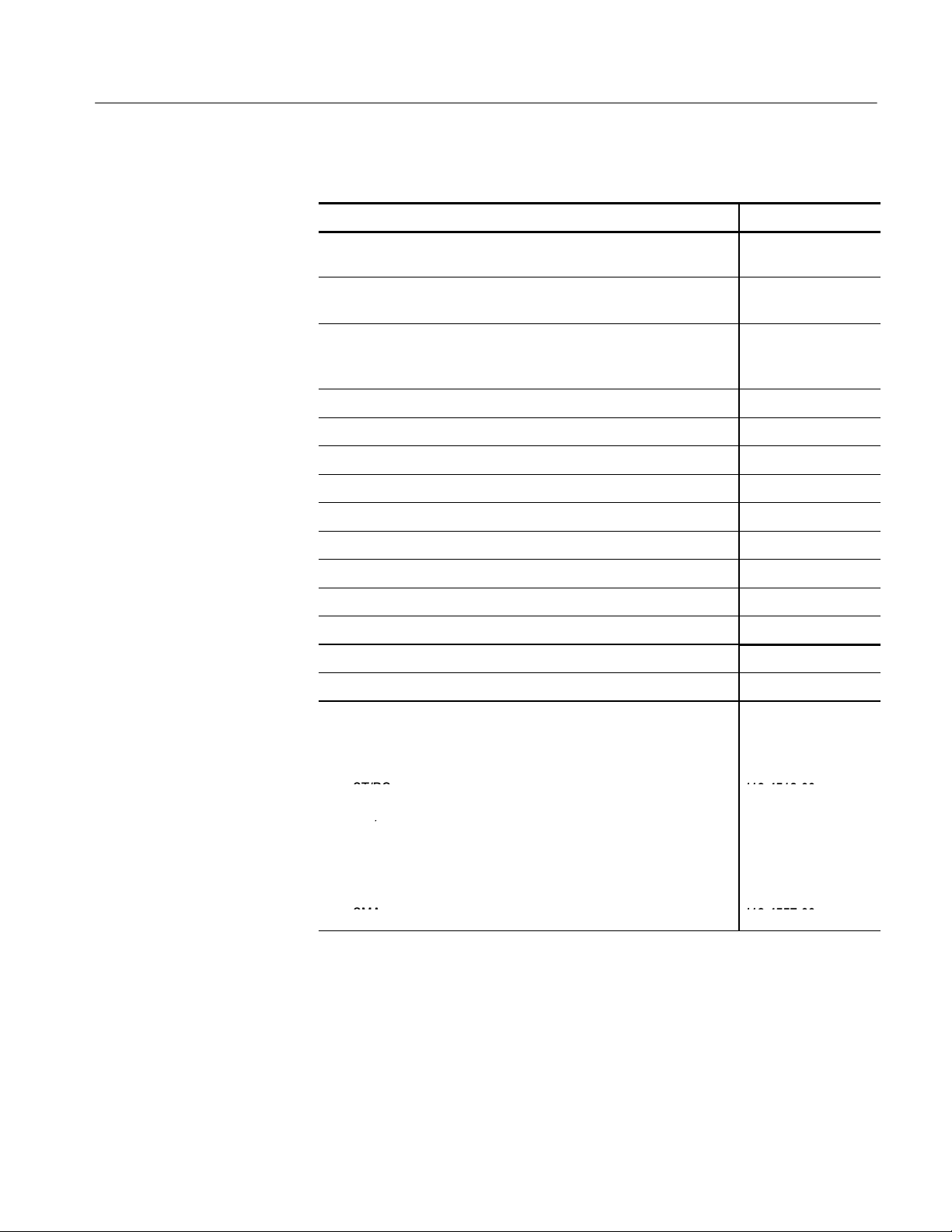
Accessories & Options
c
a
a
p
OpticalConnectorAdapter
s,CSA7404&CSA7154
FC/PC11
9-511
5-00SC/PC
/
Diamond
2.511945560
0
Diamond
3.511
9-455
8-00SMA
A
Table 1- 6: Optional accessories (Cont.)
Accessory Part number
TekConnect-to-BNC adapter, CSA7404, CSA7154, TDS7404,
TDS7254, TDS7154, TDS6604 & TDS6404
TekConnect-to-N adapter, CSA7404, CSA7154, TDS7404, TDS7254,
TDS7154, TDS6604 & TDS6404
TekConnect high impedance buffer amplifier, 500 MHz 1 MΩ BNC-toTekConnect adapter (includes one P6139A probe), CSA7404,
CSA7154, TDS7404, TDS7254, TDS7154, TDS6604 & TDS6404
VocalLink Pro Voice Controlled Software VCLNKP
VocalLink Basic Voice Controlled Software VCLNKB
Wavewriter: AWG and waveform creation software S3FT400
WSTRO WaveStar Software WSTRO
GPIBcable(1m) 012-0991-01
GPIBcable(2m) 012-0991-00
RS-232 cable 012-1298-xx
PS-2 keyboard 118-9402-00
USB Keyboard 119-6633-xx
Centronics cable 012-1214-xx
Replacement hard disk 650-4271-xx-
TCA-BNC
TCA-N
TCA-1MEG
Opti
l ConnectorAd
ST/PC 119-4513-00
DIN/PC 47256 119-4546-00
Diamond 2.5 119-4556-00
2.5
SM
ters,CSA7404 & CSA7154
119-5116-00
119-4517-00
119-4557-00
-
-
-
-
CSA7000 Series, TDS7000 Series, & TDS6000 Series Instruments User Manual
1- 43
Page 66

Accessories & Options
Table 1- 6: Optional accessories (Cont.)
Accessory Part number
Dust cap, optical, CSA7404 & CSA7154 200-4104-00
1
Requires TCA-BNC TekConnect BNC adapter on CSA7404, CSA7154, TDS7404,
TDS7254, TDS7154, TDS6604 & TDS6404
NOTE. The P6339A probe is not supported by this instrument.
1- 44
CSA7000 Series, TDS7000 Series, & TDS6000 Series Instruments User Manual
Page 67

Operational Maps
This chapter acquaints you with how the instrument functions and operates. It
consists of several maps that describe the system, its operation, and its documentation:
H Documentation Map, on page 2--2, lists the documentation that supports the
H System Overview Maps on page 2--4, describe the high-level operating blocks
H User-Interface Map, on page 2--7, describes the elements of the User
H Front-Panel Map, on page 2--8, describes the elements of the instrument
H Display Map, on page 2--9, describes elements and operation of single-grati-
H Front Panel I/O Map, on page 2--10, describes inputs, outputs, and
instrument.
and operating cycle of the instrument.
Interface (UI) application, which provides complete control of the instrument.
front panel and cross references information relevant to each element.
cule and multiple-graticule displays.
peripherals.
H Rear Panel I/O Map, on page 2--11, describes input/output ports and
peripherals.
Tutorial (How to?) procedures are available online, as part of the online help.
For information on configuring and installing your instrument, refer to Chapter 1, Getting Started.
CSA7000 Series, TDS7000 Series, & TDS6000 Series Instruments User Manual
2- 1
Page 68

Documentation Map
This instrument ships with documents individually tailored to address different
aspects or parts of the product features and interface. The table below cross
references each document to the instrument features and interfaces it supports.
To read about… Refer to these documents: Description
Installation, Specification, &
Operation (overviews)
In Depth Operation and UI Help Online Help System
GPIB Commands
<NR3><Space>
?
User Manual
Reference Manual
Online Programmers Guide
Read the Reference for a quick overview of
instrument features and their usage.
Read the User Manual for general information about your instrument—procedures on
how to put it into service, specifications of
its performance, maps of its user interface
controls, overviews and background on its
features.
For more usage information, see Online
Help System below.
Access online help from the instrument for
context-sensitive information on virtually all
controls and elements on screen.
Online help includes procedures for using
instrument functions. See Accessing Online
Help on page 3--283.
Quickly find the syntax of a command, and
copy the command if desired. Read about
communication, error handling, and other
information on GPIB usage. This guide is
on the product software CD.
Analysis and Connectivity Tools
2- 2
Oscilloscope Analysis and Connectivity
Made Easy
TekVISA Programming Manual
VXIplug&play Driver Help
TekVISA Excel Toolbar Help
These documents consists of various
connectivity and analysis tools that you can
install and configure for your instrument.
For more information, see the Analysis and
Connectivity Support topic in the instrument
online help.
CSA7000 Series, TDS7000 Series, & TDS6000 Series Instruments User Manual
Page 69

Documentation Map
You may also want to obtain the optional service manual for this product if you
self-service or performance test this instrument. S ee Accessories & Options on
page 1--37.
CSA7000 Series, TDS7000 Series, & TDS6000 Series Instruments User Manual
2- 3
Page 70

System Overview Maps
The instrument is a highly capable waveform acquisition, test, and measurement
system. The following model provides background information on its operation,
which, in turn, may provide you insight on how the instrument can be used.
Functional Model Map
CH 1-- 4
Recovered clock output
Recovered data output
Electrical output
Optical input
Digital Signal Acquisition
Input channels
Acquisition
Amplitude
scaling
page 3--20
Trigger
system
page 3--71
Optical-to-electrical
converter
CSA7000 Series
page 3--26
system
Timebase
system
pages
3--124,
3--185
Signal Processing
& T ransformation
DSP
pages
3--147,
3--185,
Output &
Storage
CH 1-- 4
Ref 1--4
Math 1 --4
Display & UI
Page 3--123
2- 4
The model comprises four high-level subsystems or processes (embodying a
variety of hardware and software functions) and the data that connects them:
H Digital Signal Acquisition System. Acquires a waveform record from each
signal that you input to each channel using the following subsystems:
H Input Channels. Conditions the input signal, primarily through the use
of analog hardware, before the signal is converted to digital form.
CSA7000 Series, TDS7000 Series, & TDS6000 Series Instruments User Manual
Page 71

System Overview Maps
H Trigger System. Recognizes a specific event of interest on the input trigger
signal and informs the Timebase of the occurrence of the event. Also
provides recovered clock and data signals (optional on TDS 7000 Seriesand
TDS6000 Series instruments).
H Timebase System. Tells the Acquisition system to start an acquisition
cycle (that is, to convert from analog to digital). In more general terms,
synchronizes the capturing of digital samples in the Acquisition system
to the trigger events generated from the Trigger system.
H Acquisition System. Performs the actual A/D conversion and storing of
digital samples.
H Optical-to-Electrical Converter. CSA7000 Series: Converts optical
signals to electrical signals.
H DSP Transformation System. Performs a variety of transformations or
operations, beginning with the most fundamental data element(s) in the
system, the Channel Waveform(s). Waveform math operations, automatic
measurements, spectral waveforms, and histogram generation are examples.
H Input/Output Systems. Provides output (and sometimes input) of instru-
ment-data elements in a form suitable to the user and also provides user
input control.
The process overview that follows describes each step in the top-level cycle of
instrument operation.
CSA7000 Series, TDS7000 Series, & TDS6000 Series Instruments User Manual
2- 5
Page 72

System Overview Maps
Yes
Process Overview Map
Process Overview
Yes
Stop condition?
No
Implement
pretrigger points
No
Idling...
setup
Acquire
Trigger
accepted
Yes
Reset
Abort
Power on
Power down
Arm
Process Block Description
1. The instrument starts in the idle state; it enters this state
upon power up, upon receiving most control setting changes,
or upon finishing acquisition tasks.
2. Control settings are implemented as they are requested.
When you toggle the RUN/STOP control to RUN, the
instrument starts the hardware.
3. The instrument acquires samples until the pretrigger portion
of the waveform record (channel) being acquired is filled.
4. The instrument then begins waiting for a trigger. Acquiring
continues to take place, keeping the pretrigger points current,
until triggering criteria are met or a trigger is forced (Auto
trigger mode only) and the instrument accepts a trigger.
2- 6
No
Acquire
posttrigger
points
5. The instrument acquires samples until the posttrigger portion
of the waveform record (channel) being acquired is filled.
6. If averaging, enveloping, or waveform database is on, the
record becomes part of the multi-acquisition record that these
Waveform
record
complete?
Yes
modes produce. The process loops back to step 3 above to
acquire additional records until the number of acquisitions
required for the acquisition mode currently set are processed,
and then processing continues to step 7 below.
7. At this point the acquisition record is in DSP memory and is
Waveform
available
available to the instrument for measurement of its
parameters, display, and so on.
The instrument then checks for a user-specified stop
condition and either returns to its idle state or continues at
step 3, according to what it finds.
CSA7000 Series, TDS7000 Series, & TDS6000 Series Instruments User Manual
Page 73

User Interface Map -- Complete Control and Display
Menu Bar: Access to data I/O,
printing, online help system, and
instrument functions here
Status Bar: Display of
acquisition status, mode, and
number of acquisitions; trigger
status; warnings; date; and time
Buttons/Menu. Touch to
toggle between tool-bar
and menu-bar modes
Multipurpose Knob
Readouts. Adjust
parameters controlled by
Display: Live, reference, & math
waveforms display here, along
with cursors
Waveform Handle: Touch and drag
to change vertical position of
waveform. Touch the handle and
change the position and scale using
the multipurpose knobs
Controls Status: Quick reference to
vertical, horizontal, and trigger
selections, scale, and parameters
multipurpose knobs
Readouts: Display
cursor readouts and
measurement
readouts in this area,
selectable from the
menu bar or tool bar
If a control menu is
displayed, these
readouts move to the
graticule area
CSA7000 Series, TDS7000 Series, & TDS6000 Series Instruments User Manual
2- 7
Page 74
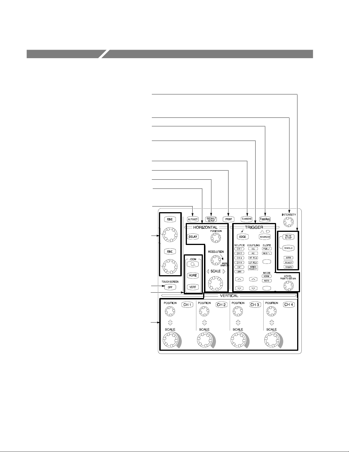
Front-Panel Map -- Quick Access to Most Often Used Features
Use these buttons to start and stop acquisition or start a single
acquisition sequence. The ARM, READY, and TRIG’D lights
Turn knob to adjust waveform intensity. Page 3--53.
Push button to turn Fast Acquisition on or off (7000 Series only).
Use these knobs and buttons to set the trigger parameters. Push
ADVANCED to display additional trigger functions. Pages 3--71
Push to return settings to default values. Page 3 --18.
Horizontally scale, position, delay, and set record length
show the acquisition status. Page 3 --82.
Page 3--47.
and 3--88.
Push to turn cursors on or off. Page 3 --160.
Push to make a hard copy. Page 3--277.
(resolution) of selected waveform. Page 3--23.
Push to automatically set up the vertical, horizontal, and trigger
Turn the multipurpose knobs to adjust parameters selected from
Push ZOOM to add a magnified graticule to the display. Push
Turn channel displays on and off. Vertically scale or position the
waveform. Change the input termination (TDS7104 & TDS7054).
controls based on selected channels. Page 3--17.
the screen interface. Push a Fine button to toggle between
normal and fine adjustment with its multipurpose knob.
Page 3--165.
Push to turn the touch screen on and off. Page 3 --129.
HORIZ or VERT to select the axis to magnify. Page 3--131.
Page 3--8.
2- 8
CSA7000 Series, TDS7000 Series, & TDS6000 Series Instruments User Manual
Page 75
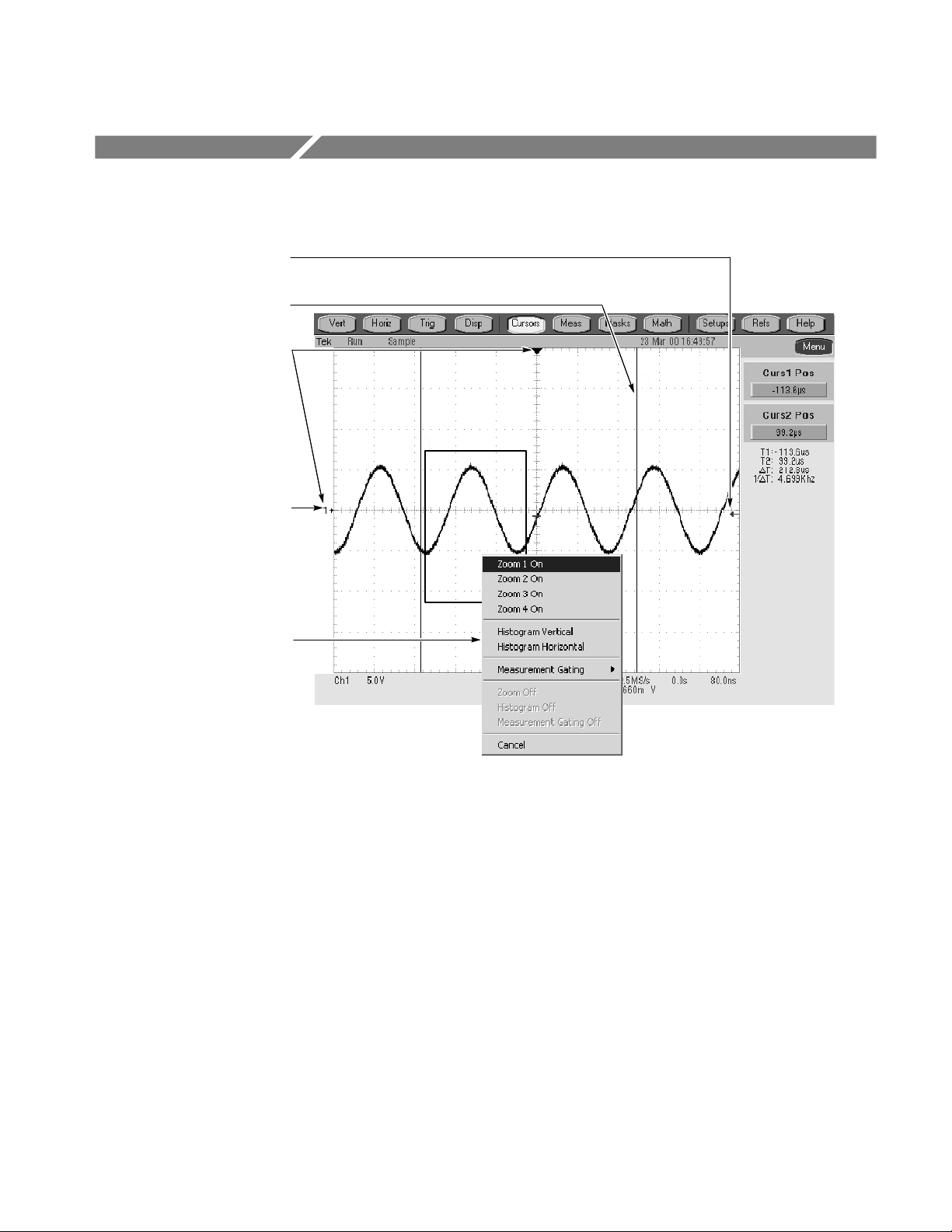
Display Map -- Single Graticule
Drag icon to change the trigger
level
Drag cursors to measure
waveforms on screen
Drag the position icons to
reposition a waveform
Click icon to assign multipurpose
knobs to waveform vertical
position and scale
Drag across the waveform area to
zoom the boxed waveform segment.
Also enable/disable histograms and
measurement gating
CSA7000 Series, TDS7000 Series, & TDS6000 Series Instruments User Manual
2- 9
Page 76

Front Panel I/O Map
CSA7000 Series
Floppy disk drive
Probe compensation
output
Recovered clock output
Recovered data output
O/E converter electrical output
Probe compensation
output
Auxiliary trigger input
CH 3 SIGNAL OUTPUT; scale and
offset controlled by CH3 controls
Optical input
Channel
inputs
TDS7404, TDS7254, TDS7154, TDS6604, & TDS6404
Auxiliary trigger output
Channel
inputs
TDS7104 & TDS7054
Ground terminal
Ground terminal
Auxiliary trigger input
Auxiliary trigger output
CH 3 SIGNAL OUTPUT; scale and
offset controlled by CH3 controls
2- 10
Ground terminal
Probe
compensation
output
Channel
inputs
CSA7000 Series, TDS7000 Series, & TDS6000 Series Instruments User Manual
Page 77
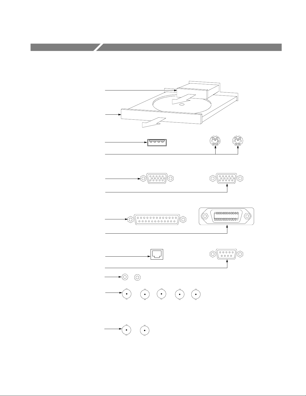
Rear Panel I/O Map
Removable hard disk drive to provide
individual environment for each user or to
secure data. Press to release
CDROM-RW drive accessible from
Windows. Press to open
USB connector for mouse or
keyboard and mouse
PS-2 connectors for mouse and keyboard
Upper VGA port to connect a
monitor for side-by-side display
Lower VGA port to connect a
monitor for instrument display
Parallel port (Centronics) to
connect printer or other device
GPIB port to connect to controller
RJ-45 connector to connect to network
COM1 serial port
Connectors for speaker and microphone
CSA7000 Series: Auxiliary (external
trigger) input. Auxiliary (trigger) output
signal. Analog (CH 3) signal output; scale
and offset controlled by CH3 controls.
External reference input and internal
reference output
PCMCIA slots for two type-1 cards,
TDS7000 Series & TDS6000 Series:
two type-2 cards, or one type-3 card
External reference input and internal
reference output
CSA7000 Series, TDS7000 Series, & TDS6000 Series Instruments User Manual
2- 11
Page 78

Rear Panel I/O Map
2- 12
CSA7000 Series, TDS7000 Series, & TDS6000 Series Instruments User Manual
Page 79

Overview
This chapter describes in depth how the many features of the instrument operate.
Please note the following points on using this chapter:
H Each section in this chapter provides background information needed to
operate your instrument effectively as well as the higher-level procedures for
accessing and using the features. These procedures emphasize using the front
panel when possible.
H Lower-level, detailed usage procedures are in the online help system.
The table that follows on page 3--2 lists operating tasks and the sections in this
chapter that document those tasks.
CSA7000 Series, TDS7000 Series, & TDS6000 Series Instruments User Manual
3- 1
Page 80

Overview
Tasks or topics
Signal Input Acquiring waveforms Acquiring Waveforms Overview of section contents 3--7
Subtasks or subtopics Section title Contents Page no.
Signal Connection and
Conditioning
To Set Up Signal Input Setting up signal input 3--13
To Autose t the
Instrument
To Reset the Instrument Resetting the instrument 3--18
To Get More Help Accessing the online help 3--19
Input Conditioning
Background
Setting Acquisition
Controls
To Set Acquisition Modes Set up of the acquisition system 3--34
To Start and Stop
Acquisition
To Set Roll Mode Setting up roll mode 3--38
Acquisition Control
Background
Overview of signal connection and
conditioning techniques and setups
Automatic setup of the acquisition,
triggering systems and input channels
Background information on input signal
conditioning
Background and setup of acquisition
controls and roll mode
Starting and stopping acquisitions 3--37
Background information on acquisition
controls
3--8
3--17
3--19
3--26
3--39
Using Fast Acquisition
Mode
To Turn Fast Acquisitions
On and Off
Using FastFrame Overview and setup of FastFrame 3--56
To Set FastFrame Mode Setting up FastFrame mode 3--58
Time Stamping Frames Setting up FastFrame time stamps 3--60
O/E Converter
CSA7000 Series only
Front Panel Connectors
CSA7000 Series only
Wavelength, Filter, and
Bandwidth Selection
CSA7000 Series only
Optical bandwidth
CSA7000 Series only
Overview and setup of Fast Acquisition
mode
Turning fast acquisitions on and off 3--50
Overview and reference to documentation
on using optical signals and the O/E
Converter
Overview of O/E Converter front-panel
connectors
Overview of optical controls 3--67
Overview of optical bandwidth 3--68
3--47
3--63
3--64
3- 2
CSA7000 Series, TDS7000 Series, & TDS6000 Series Instruments User Manual
Page 81

Overview
Tasks or topics
Signal Input Triggering waveforms Triggering Background on basic trigger operation 3--71
Triggering Concepts Background on triggering concepts 3--72
Triggering From the Front
Panel
Access Procedures Setting up triggers with front-panel
To Check Trigger Status Checking trigger status 3--82
Additional Trigger
Parameters
Advanced Triggering Overview and setup for triggering on
To Trigger on a Glitch Setting up glitch triggering 3--94
To Trigger on a Runt Pulse Setting up runt pulse triggering 3--96
Trigger Based on Pulse
Width
To Trigger Based on
Transition Time
Trigger Based on Pulse
Timeout
Using the front-panel edge trigger controls 3--78
controls
Using additional trigger controls 3--83
specific pulse and logic conditions
Setting up pulse width triggering 3--99
Setting up transition time triggering 3--101
Setting up pulse timeout triggering 3--104
Page no.ContentsSection titleSubtasks or subtopics
3--78
3--88
Trigger on a Pattern Setting up pattern triggering 3--105
To Trigger on a State Setting up state triggering 3--109
To Trigger on Setup/Hold
Time Violations
Sequential Triggering Overview and setup f or triggering after
To Trigger on a Sequence Setting up triggering on a sequence 3--118
Comm Triggering
(optional on TDS7000
Series)
Serial Pattern Triggering
(optional on TDS7000
Series)
Setting up setup/hold time violation
triggering
time delay and triggering on events
Overview and reference to documentation
on using communications triggering
Overview and reference to documentarian
on using serial pattern triggering
3--110
3--113
3--122
3--122
CSA7000 Series, TDS7000 Series, & TDS6000 Series Instruments User Manual
3- 3
Page 82

Overview
Tasks or topics
Display Features Using the Display Displaying Waveforms Using display features and customizing
the display
Data Processing
(Calculation)
Using the Waveform
Display
To Display Waveforms in
theMainGraticule
Setting Zoom Controls Overview and use of Zoom 3--131
To Zoom Waveforms Setup to zoom a waveform 3--132
Customizing the Display Customizing display elements 3--138
Set Display Styles Overview of display adjustments you can
Customize Graticule and
Waveforms
Taking Measurements Measuring Waveforms Setup for measuring parameters 3--147
Taking Automatic
Measurements
To Take Autom a t i c
Measurements
To Localize a
Measurement
Overview of display features and setup of
the display
Display adjustments you can make 3--129
make
Overview of graticule and waveform
adjustments you can make
Overview and setup for taking automatic
measurements
Set for automatic measurements 3--153
Setup to measure a segment of a
waveform
Page no.ContentsSection titleSubtasks or subtopics
3--123
3--124
3--141
3--144
3--148
3--159
Taking Cursor Measurements
To Set the Cursor Sources Selecting the cursor sources 3--165
Taking Histograms Overview and setup for taking Histograms 3--168
To Start and Reset
Histogram Counting
Optimizing Measurement
Accuracy
To Compensate the
Instrument
Overview and setup for taking cursor
measurements
Setup for histogram counting 3--169
Increase accuracy by compensating the
instrument and adjusting deskew
Setup to compensate the instrument 3--172
3--160
3--171
3- 4
CSA7000 Series, TDS7000 Series, & TDS6000 Series Instruments User Manual
Page 83

Overview
A
,
A
,
ATan,
,
ASi
n,ACo
s,ATa
n,Sin
h
E
xp,M
agnitude,Rea
l
Tasks or topics
Data Processing
(Calculation)
(Cont.)
Taking Measurements
(Cont.)
Math (+. --, /, *, Chs, Exx,
≡,,≠,,>,<,
Intg, Diff, Fabs,Sin,Cos,
Tan, Min, Max, Ceil, Floor,
Sin
Cos
Cosh, Tanh, Average,
Invert, Sqrt, Log 10, Log e,
Phase, and Imag)
Spectral Math operations Defining Spectral Math
Sinh
To Connect the Probe
Calibration Fixture
To Calibrate Probes Improving measurement accuracy by
To Compensate Passive
Probes
To Deskew Channels Adjusting delay between channels 3--181
Serial Mask Testing Pointer to mask testing information 3--184
Creating and Using Math
Waveforms
Defining Math Waveforms Overview of performing math operation on
,
ToDefineaMath
Waveform
,
Operations on Math
Waveforms
To Use Math Waveforms Example setups for measuring and
Waveforms
Page no.ContentsSection titleSubtasks or subtopics
Connecting the probe calibration and
deskew fixture to the instrument
calibrating your probes
Compensating passive probes 3--180
Functions for processing waveforms,
extracting segments of waveforms, etc.
waveforms
Defining math waveforms 3--194
Overview of measuring and adjusting
math waveforms
adjusting math waveforms
Functions for frequency domain analysis
of your waveforms.
3--173
3--177
3--185
3--186
3--197
3--198
3--202
Optimizing
Measurement
Accuracy
Instrument compensation
and compensation or
calibration of probes
To Select a Predefined
Spectral Math Waveform
To Define A Spectral Math
Waveform
Spectral Math Example An example of performing spectral
Optimizing Measurement
Accuracy
Selecting a predefined spectral math
waveform
Setup to define a spectral math waveform 3 --231
analysis of a signal
Procedures for compensating the instrument, compensating passive probes, and
calibrating active, voltage probes
3--230
3--239
3--171
CSA7000 Series, TDS7000 Series, & TDS6000 Series Instruments User Manual
3- 5
Page 84

Overview
,
Tasks or topics
Data Input and
Output
All uploading and downloading of waveforms,
calculation results, and
other data
Page no.ContentsSection titleSubtasks or subtopics
Data Input/Output Primary reference for uploading and
downloading of any data to or from the
instrument
Saving and Recalling a
Setup
To Save Your Setup Savi ng an instrument setup 3--248
To Recall Your Setup Recalling an instrument setup 3--251
Saving and Recalling
Waveforms
To Save Your Waveform Saving a waveform 3--254
To Recall Your Waveform Recalling a saved waveform 3--257
To Clear References Setup to clear references 3--260
Exporting and Copying
Waveforms
To Export Your Waveform Exporting a waveform to a file 3--263
To Use an Exported
Waveform
To Copy Your Waveform Copying a waveform to the clipboard 3 --273
Background and setup for saving and
recalling setups
Background and setup for saving and
recalling waveforms
Background and setup for exporting
waveforms and using exported waveforms
Using an exported waveform in Excel 3--271
3--245
3--245
3--253
3--262
Printing Waveforms Background and setup for printing
waveforms
To Date/Time Stamp
Hardcopies
Remote Communication
Help Using Online Help Accessing Online Help Information on accessing the information
GPIB Remote Communication Information on programming the
How to Use Online Help Using the online help 3--284
Background and setup to display the date
and time
instrument over the GPIB
in the online help
3--277
3--281
3--282
3--283
3- 6
CSA7000 Series, TDS7000 Series, & TDS6000 Series Instruments User Manual
Page 85

Acquiring Waveforms
Before you can do anything (display, print, measure, analyze, or otherwise
process) to a waveform, you must acquire the signal. This instrument comes
equipped with the features that you need for capturing your waveforms before
further processing them according to your requirements. The following topics
cover capturing signals and digitizing them into waveform records:
H Signal Connection and Conditioning: How to connect waveforms to the
instrument channels; how to scale and position the channels and timebase for
acquiring waveforms.
H Setting Acquisition Controls: How to choose the appropriate acquisition mode
for acquiring your waveforms; how to start and stop acquisition.
H Acquisition Control Background: Background information on the data
sampling and acquisition process.
H Using Fast Acquisition Mode (CSA7000 Series & TDS7000 Series): Using
Fast Acquisition mode to capture and display transient events, such as
glitches or runt pulses, often missed during longer dead times that accompany normal DSO operation.
H Using FastFrame (CSA7000 Series & TDS7000 Series): Using FastFrame to
capture many records in a larger record, and then view and measure each
record individually.
H O/E Converter (CSA7000 Series): Using the Optical-to-Electrical Converter
to test optical signals.
CSA7000 Series, TDS7000 Series, & TDS6000 Series Instruments User Manual
3- 7
Page 86

Acquiring Waveforms
Storage
Channel
inputs
Auxiliary
trigger input
Input Display
Trigger
Acquisition
system
Waveform
transform
system
Horizontal
time base
NOTE. This section describes how the vertical and horizontal controls define the
acquisition of live waveforms. These controls also define how all waveforms are
displayed, both live and derived waveforms (math waveforms, reference
waveforms, and so on). The sections that follow cover display-related usage:
H Displaying Waveforms on page 3--123.
H Creating and Using Math Waveforms on page 3--185.
Signal Connection and Conditioning
This section presents overviews of the instrument features related to setting up
the input signal for digitizing and acquisition. It addresses the following topics:
H How to turn on channels and adjust vertical scale, position, and offset
H How to set horizontal scale, position, and access record-length and trigger-
position controls
H How to get a basic trigger on your waveform
3- 8
CSA7000 Series, TDS7000 Series, & TDS6000 Series Instruments User Manual
Page 87

NOTE. Terminology: This manual uses the terms vertical acquisition window and
horizontal acquisition window throughout this section and elsewhere. These
terms refer to the vertical and horizontal range of the segment of the input signal
that the acquisition system acquires. The terms do not refer to any windows or
display windows on screen.
Figure 3--1 shows the model for each input channel.
CSA7000 Series, TDS7404, TDS7254, TDS7154, TDS6604, & TDS6404
Scale = K1 * K2 * K3
Coupling
+
---
Vertica l
offset
Σ
K1 K2 K3
External
attenuation
Probe
Input
termination
50 Ω
Vertica l
scale
+
+
Vertica l
position
Acquiring Waveforms
To the
Σ
Bandwidth
limit
remainder
of the
acquisition
system
TDS7104 & TDS7054
Scale = K1 * K2 * K3
Coupling
+
---
Vertica l
offset
Σ
K1
External
attenuation
K2
Probe
Input
termination
Figure 3- 1: Input and Acquisition Systems and Controls
Use input conditioning to ensure the instrument acquires the data that you want
to display, measure, or otherwise process. To ensure the best possible data for
displaying and further processing, do the following:
H Set the vertical scale to control the size of the vertical acquisition window
for each channel to capture part or all of the vertical amplitude of the input
signal. When vertical scaling is set to capture only a fraction of the input
signal range (for increased detail), the vertical offset control may be used to
determine which portion of the input signal is captured by the vertical
acquisition window.
50 Ω
K3
Vertica l
scale
+
+
Vertica l
position
To the
Σ
Bandwidth
limit
remainder
of the
acquisition
CSA7000 Series, TDS7000 Series, & TDS6000 Series Instruments User Manual
3- 9
Page 88

Acquiring Waveforms
H Set horizontal scale to control the size of the horizontal acquisition window
to capture as much as you want of the input signal(s). Set the horizontal
position to delay the window relative to a trigger and to control where in the
input signal (data stream) that the horizontal acquisition window acquires.
For more background on acquisition window concepts, see Input Conditioning
Background on page 3--19.
The instrument can automatically obtain and display a stable waveform of usable
size. Pushing the Autoset button automatically sets up the instrument controls
based on the characteristics of the input signal. Autoset is much faster and easier
than a manual control-by-control setup.
The instrument can also be reset to its factory default settings.
Usage of some input conditioning controls or features may be limited when other
control settings are in effect. Voltage offset is incompatible with reference
waveforms because offset is an acquisition control.
Connecting and
Conditioning Your Signals
Read the following topics related to waveform acquisition; they provide details
that can make it easier to set up and acquire your waveforms.
Probes and Signal Connection. Select the probe or cable that brings the signal into
the instrument. Choose the probe or cable that best fits your acquisition task,
whether it is connecting an active probe to test a digital circuit, or connecting to
a test fixture through SMA cables to characterize a device. The connection to the
instrument depends on your application.
Tektronix provides a variety of probes and cables for this product. For a list of
probes available for use, see Accessories and Options on page 1--37. You can
also check your Tektronix catalog for connection accessories that may support
your application. More information about your probes can be found in the user
manual for your probes.
Four acquisition channels are available. Each channel can be displayed as a
waveform or can contribute waveform data to other waveforms (math and
reference waveforms for example).
3- 10
CSA7000 Series, TDS7000 Series, & TDS6000 Series Instruments User Manual
Page 89

Acquiring Waveforms
Coupling. All instruments and probes specify a maximum signal level. (See
Specifications in your user manuals for exact limits.) Exceeding the limit, even
momentarily, may damage the input channel. Use external attenuators, if
necessary, to prevent exceeding the limits.
Coupling determines whether an input signal is directly connected to the input
channel, connected through a DC blocking capacitor (TDS7104 & TDS7054), or
not connected at all. These three choices are refereed to as DC coupling, AC
coupling, and GND coupling.
The input resistance of each input channel is either 50 Ω or you can select 50 Ω
or 1 MΩ, depending on the model. To properly terminate signals in other
impedance environments, use an adapter.
All probes expect a specific coupling and input termination. Both coupling and
input termination resistance are displayed on screen.
Scaling and Positioning. These key controls determine the portion of the input
signal presented to the acquisition system:
H Set vertical scaling, positioning, and DC offsets to display the features of
interest on your waveform and avoid clipping. (See Note that follows.)
Vertical Acquisition Window Considerations on page 3--20 describes the
vertical acquisition window.
Clipped
Acquired waveform Displayed waveform
CSA7000 Series, TDS7000 Series, & TDS6000 Series Instruments User Manual
3- 11
Page 90

Acquiring Waveforms
H Set horizontal scale, position, and resolution (record length) so that the
acquired waveform record includes the waveform attributes of interest with
good sampling density on the waveform. The settings that you make define
the horizontal acquisition window (see Horizontal Acquisition Window
Considerations on page 3--23).
NOTE. Waveform data outside the vertical acquisition window is clipped; that is,
the data is limited to the minimum or maximum boundaries of the vertical
acquisition window. This limiting causes inaccuracies in amplitude-related
measurements. Note that the acquisition window also includes 1 division above
and below the displayed graticule area. See Vertical Acquisition Window
Considerations on page 3--20.
Trigger and Display. Set basic trigger controls to gate waveform acquisition, and
use the display to interactively scale, position, and offset waveforms. See the
sections Triggering on page 3--71 and Displaying Waveforms on page 3--123.
Flexible Control Access. This manual focuses on basic setup through the front
panel, and then through use of the User Interface (UI) Application displayed on
screen. The online help system also documents the UI.
3- 12
CSA7000 Series, TDS7000 Series, & TDS6000 Series Instruments User Manual
Page 91

Acquiring Waveforms
To Set Up Signal Input
Use the procedure that follows when setting up the instrument to scale and
position input signals for acquisition. For more information, display online help
while performing the procedure.
Overview To set up si gnal input Related control elements and resources
Prerequisites
Connect input
signal
1. The acquisition system should be set to run
continuously.
See page 3--34 for acquisition setup and
page 3--71 for trigger setup.
2. Connect to the signal to be acquired using proper
probing and connecting techniques.
Note. For more details on control over input setup, push
the Vert button to display the Vertical control window,
and then touch the HELP button.
Select the
input signal
channel
3. Push a channel button (CH 1--CH 4) to select the
signal channel.
A channel button lights when its channel is on.
CSA7000 Series, TDS7000 Series, & TDS6000 Series Instruments User Manual
3- 13
Page 92

Acquiring Waveforms
Overview Related control elements and resourcesTo set up signal input (Cont.)
Select input
termination
Select input
coupling
TDS7104 and TDS7054 only:
4. Push an input termination button to toggle between
1MΩ and 50 Ω input termination.
Hint. Some probes force the instrument to set the
termination that the probe requires.
5. Touch Vert to display the Vertical control window. To
change the input coupling, select the channel tab and
then select from:
H DC to couple both the AC and DC components of
an input signal
H TDS7104 and TDS7054: AC to couple only the AC
components of an input signal
H GND to disconnect the input signal from the
acquisition
Touch Close to close the window.
Note. CSA7000 Series: If the O/E Electrical Out--to-CH1 adapter is installed, the Termination, Coupling, and
Bandwidth selections are replaced with Wavelength and
Dark Level selections.
3- 14
CSA7000 Series, TDS7000 Series, & TDS6000 Series Instruments User Manual
Page 93
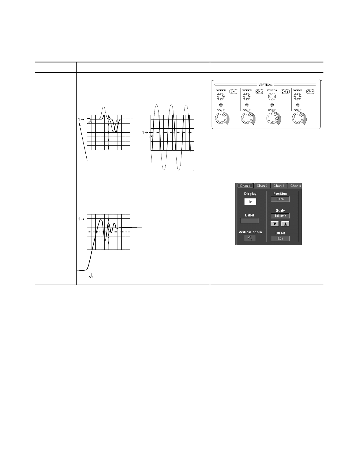
Overview Related control elements and resourcesTo set up signal input (Cont.)
Acquiring Waveforms
Set vertical
acquisition
window
6. Use the vertical knobs to scale and position the
waveform on screen.
Positioned vertically Scaled vertically
Dragging the waveform
handle also positions the
waveform.
7. Touch Vert to display the Vertical control window.
To change the offset, touch the Offset control and
turn the multipurpose knob to adjust the offset.
CSA7000 Series, TDS7000 Series, & TDS6000 Series Instruments User Manual
3- 15
Page 94
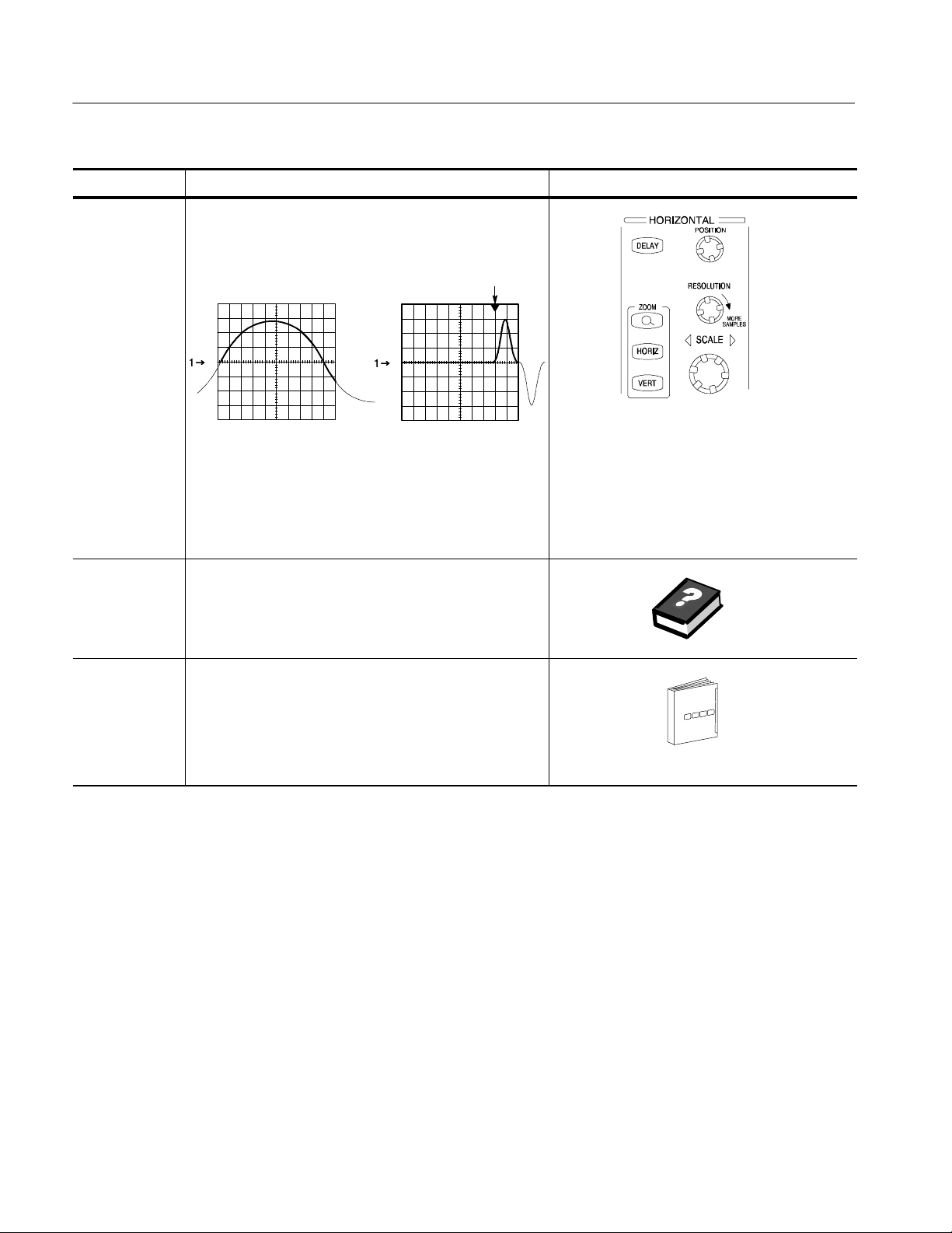
Acquiring Waveforms
Overview Related control elements and resourcesTo set up signal input (Cont.)
Set horizontal
acquisition
window
For help
8. Use horizontal knobs to scale and position the waveform
on screen and to set record length.
Dragging the reference icon
also positions the waveform.
Positioned horizontallyScaled horizontally
The Resolution knob sets the record length. (See
discussion on page 3--24.)
If required to stabilize the display, push LEVEL to set the
trigger level to 50%.
9. For more information on the controls described in this
procedure, push the Vert or Horiz button. Touch the
HELP button in the toolbar.
Continue with
acquisition
setup
10. To finish acquisition setup, you must set the
acquisition mode and start the acquisition.
See To Set Acquisition Modes on page 3--34.
3- 16
CSA7000 Series, TDS7000 Series, & TDS6000 Series Instruments User Manual
Page 95
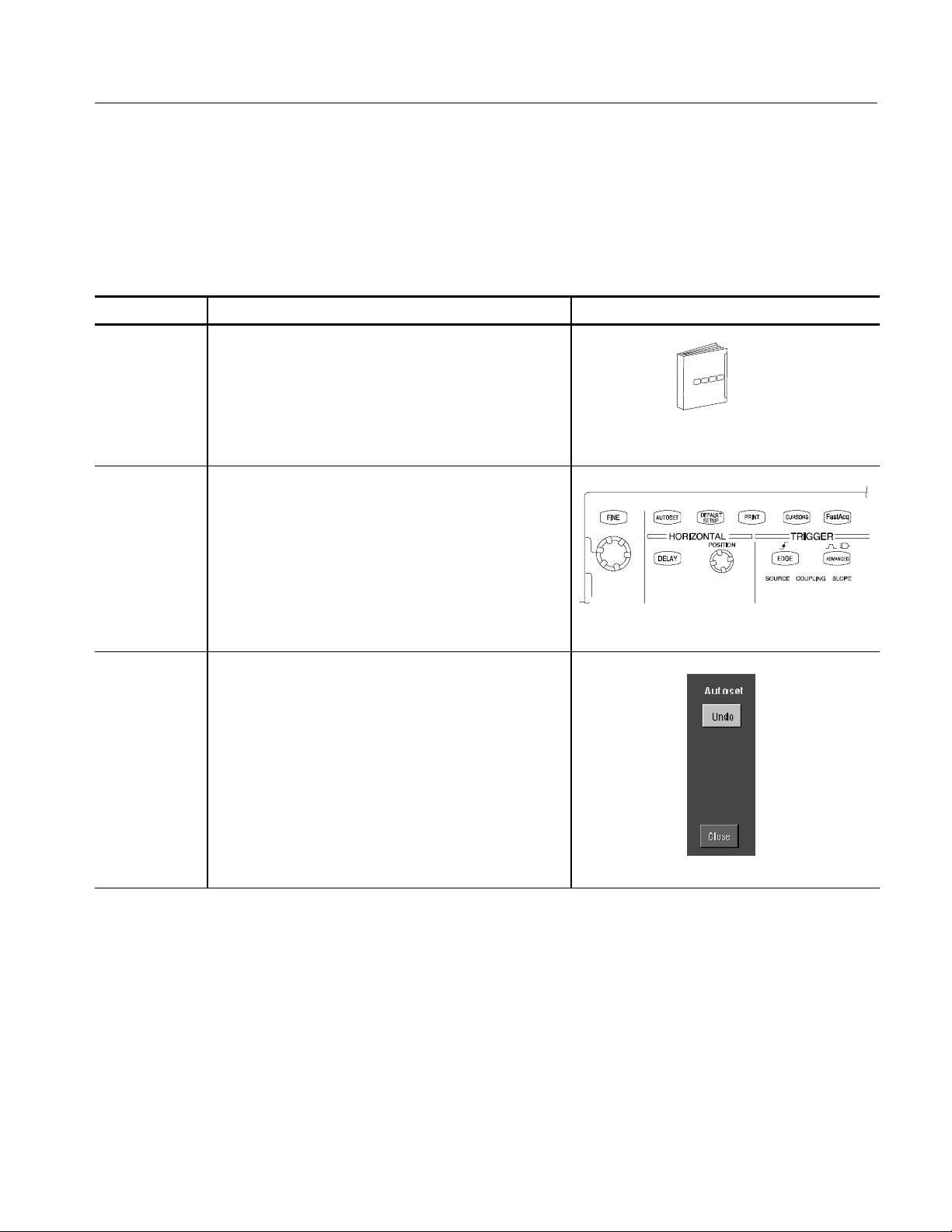
Acquiring Waveforms
To Autoset the Instrument
Autoset automatically sets up the instrument controls (acquisition, display,
horizontal, trigger, and vertical) based on the characteristics of the input signal.
Autoset is much faster and easier than a manual control-by-control setup. When
the input signal is connected, do an autoset to automatically set up the instrument:
Overview To autoset the instrument Control elements and resources
Prerequisites
Execute
1. Signals must be connected to channels. A triggering
source must be provided.
See page 3--71 in this manual for trigger setup
information.
2. Push the Autoset button to execute an Autoset.
If you use Autoset when one or more channels are
displayed, the instrument selects the lowest numbered
channel for horizontal scaling and triggering. All
channels in use are individually vertically scaled.
If you use Autoset when no channels are displayed, the
instrument turns on channel one (CH 1) and scales it.
Execute
Autoset Undo
3. The Autoset Undo control window opens automatically
after an Autoset operation. Click Undo if you want to
undo the last Autoset.
Only the parameters that were set by the last Autoset
are undone. Parameters that you changed that are not
controlled by Autoset retain their settings.
If you don’t want this window to appear, set the
Utilities/User Preferences/Autoset Undo button to Off.
You can still do an Autoset Undo using the Horiz/Acq
menu.
CSA7000 Series, TDS7000 Series, & TDS6000 Series Instruments User Manual
3- 17
Page 96

Acquiring Waveforms
Overview Control elements and resourcesTo autoset the instrument (Cont.)
Prompt
Done
4. Select User Preferences in the Utilities menu to display
the Prompt Before Action window. Touch Autoset to
toggle between ON and OFF:
H OFF to set up for performing an autoset when t he
AUTOSET button is pushed
H ON to set up for displaying a prompt before
performing an autoset when the AUTOSET button
is pushed
Touch Close to save your prompt selection.
To Reset the Instrument
NOTE. Autoset may change the vertical position to position the waveform
appropriately. It sets vertical offset to 0 V unless an offsetable probe is attached.
If you are not using an offsetable probe and your signal contains offset (such as
the probe compensation signal), you may need to adjust the Vertical Offset and
SCALE to display the signal.
You may want to revert to the factory default setup; if so, reset the
instrument:
Overview To reset the instrument Control elements and resources
Prerequisites
Execute
1. The instrument is powered up and running.
See Powering On the Instrument on page 1--9.
2. Push the DEFAULT SETUP button.
3- 18
CSA7000 Series, TDS7000 Series, & TDS6000 Series Instruments User Manual
Page 97

Acquiring Waveforms
To Get More Help
You can get help on the vertical and acquisition controls by accessing online
help:
Overview To get more help Control elements and resources
Prerequisites
Access
vertical set up
1. Instrument powered up and running.
2. Touch the Help button in toolbar mode or select Help on
Window from the Help menu in menu bar mode.
help
3. You can also select topics related to the vertical controls
from the online help Contents/Index/Find window: select
Contents and Index in the Help menu, as shown at right.
See Powering On the Instrument on page 1--9.
Input Conditioning
Background
This section contains background information that can help you more effectively
set up the acquisition window of each channel.
Input. This instrument samples in real-time or random equivalent-time; both
sampling systems provide pretrigger information by using the trigger to stop an
already running acquisition. Both sampling systems also sample the input after it
is scaled, providing improved input protection and dynamic range.
CAUTION. To prevent damage to the acquisition system, do not overdrive the
inputs and observe static-safe procedures
CSA7000 Series, TDS7000 Series, & TDS6000 Series Instruments User Manual
3- 19
Page 98

Acquiring Waveforms
Autoset Considerations. Autoset acquires samples from the input signal and
attempts to take the following actions based on the input data:
H Evaluate the amplitude range of the input signals and set the size and vertical
offset of the vertical acquisition window to acquire the signal with good
resolution, but without clipping.
H Set the trigger to the approximate midlevel of the signal being autoset and
switches to edge trigger mode.
H Evaluate the signal transitions and set the horizontal scale to produce a
waveform display of 2 or 3 cycles of the input signal.
Sometimes Autoset cannot produce a correct display due to the nature of the
input signal; if so, you may have to adjust the scale, trigger, and acquisition
controls manually. Some conditions that can cause Autoset to fail are:
H No signal present
H Signals with extreme or variable duty cycles
H Signals with multiple or unstable signal periods
H Signals with too low amplitude
H No recognizable trigger signal
H Signals with a frequency <20 Hz
H Signals with a frequency above the bandwidth of the instrument
H Signals with high offset and low peak-to-peak variations
Vertical Acquisition Window Considerations. You can set the vertical size,
position, and offset of each channel independently of other channels. Vertical
scale and offset specify the vertical acquisition window for each channel. Parts of
the signal amplitude that fall within the vertical window are acquired; parts
outside (if any) are not.
The offset control subtracts a constant DC level from the input signal before the
vertical scale factor is applied, and the vertical position control adds a constant
number of divisions of signal after the scale factor is applied to the resulting
difference.
3- 20
CSA7000 Series, TDS7000 Series, & TDS6000 Series Instruments User Manual
Page 99

Acquiring Waveforms
The vertical scale and position controls have the following effects on the vertical
acquisition window and the displayed waveform:
H The vertical volts per division that you set determines the vertical size of the
acquisition window, allowing you to scale it to contain all of a waveform
amplitude or only part. Figure 3--2 on page 3--22 shows two vertical
acquisition windows that contain the entire waveform, but only one window
contains the entire waveform in the graticule on screen.
NOTE. Amplitude-related automatic measurements (for example, peak-to-peak
and RMS) will be accurate for vertical windows like those shown in Figure 3--2a
and b because neither waveform is clipped (that is, both waveforms are
acquired). But if signal amplitude were to extend outside the vertical acquisition
window, the data acquired is clipped. Clipped data causes inaccurate results if
used in amplitude-related automatic measurements. Clipping also causes
inaccurate amplitude values in waveforms that are stored or exported for use in
other programs.
If the scale of a math waveform is changed so that the math waveform is clipped,
it will not affect amplitude measurements on that math waveform.
H The vertical position adjusts the acquisition, and therefore the display, of the
acquired waveform relative to the vertical acquisition window. Figure 3--2b
shows how vertical position moves the acquired waveform vertically in the
acquisition window to place the acquired waveform in the graticule display.
H As you vary the vertical position, the vertical acquisition window moves up
and down (±5 divisions) on the waveform. With input signals that are
smaller than the window, it appears the waveform moves in the window.
Actually, the position moves the vertical acquisition window up and down
on the input signal.
CSA7000 Series, TDS7000 Series, & TDS6000 Series Instruments User Manual
3- 21
Page 100

Acquiring Waveforms
a. SCALE setting determines
the vertical acquisition
window size; here
100 mV/div x 10 divisions
(8 graticule divisions and
ᐔ1 division of position)
b. Vertical offset and position
can change the location of
the acquired waveform
within the acquisition
window, repositioning it so
its waveform appears in the
graticule
Vertica l
window
Channel
reference
indicator
Vertica l
window
Channel
reference
Indicator
1
1
Figure 3- 2: Setting vertical range and position of input channels
+0.5 Volt
+0.4 Volt
Graticule
--0.4 Volt
--0.5 Volt
+1.0 Volt
+0.7 Volt
Graticule
--0.1 Volt
--1.0 Volt
The vertical offset control affects the vertical acquisition window and the
displayed waveform as follows:
H The vertical range (window) is always centered around the offset value. It is
the voltage level at the middle of the vertical acquisition window. With no
(zero) offset, as shown in Figure 3--2 a and b, that voltage level is zero
(ground).
H As you vary vertical offset, the middle voltage level moves relative to zero.
This moves the vertical acquisition window up and down on the waveform.
With input signals that are smaller than the window, it appears the waveform
moves in the window. Actually, a larger signal shows what really happens:
the offset moves the middle of the vertical acquisition window up and down
on the input signal. Figure 3--3 shows how offset moves the acquisition
window to control the portion of the waveform amplitude the window
captures.
3- 22
CSA7000 Series, TDS7000 Series, & TDS6000 Series Instruments User Manual
 Loading...