


Reference
TDS 500D, TDS 600C & TDS 700D
Digitizing Oscilloscopes
071-0504-00
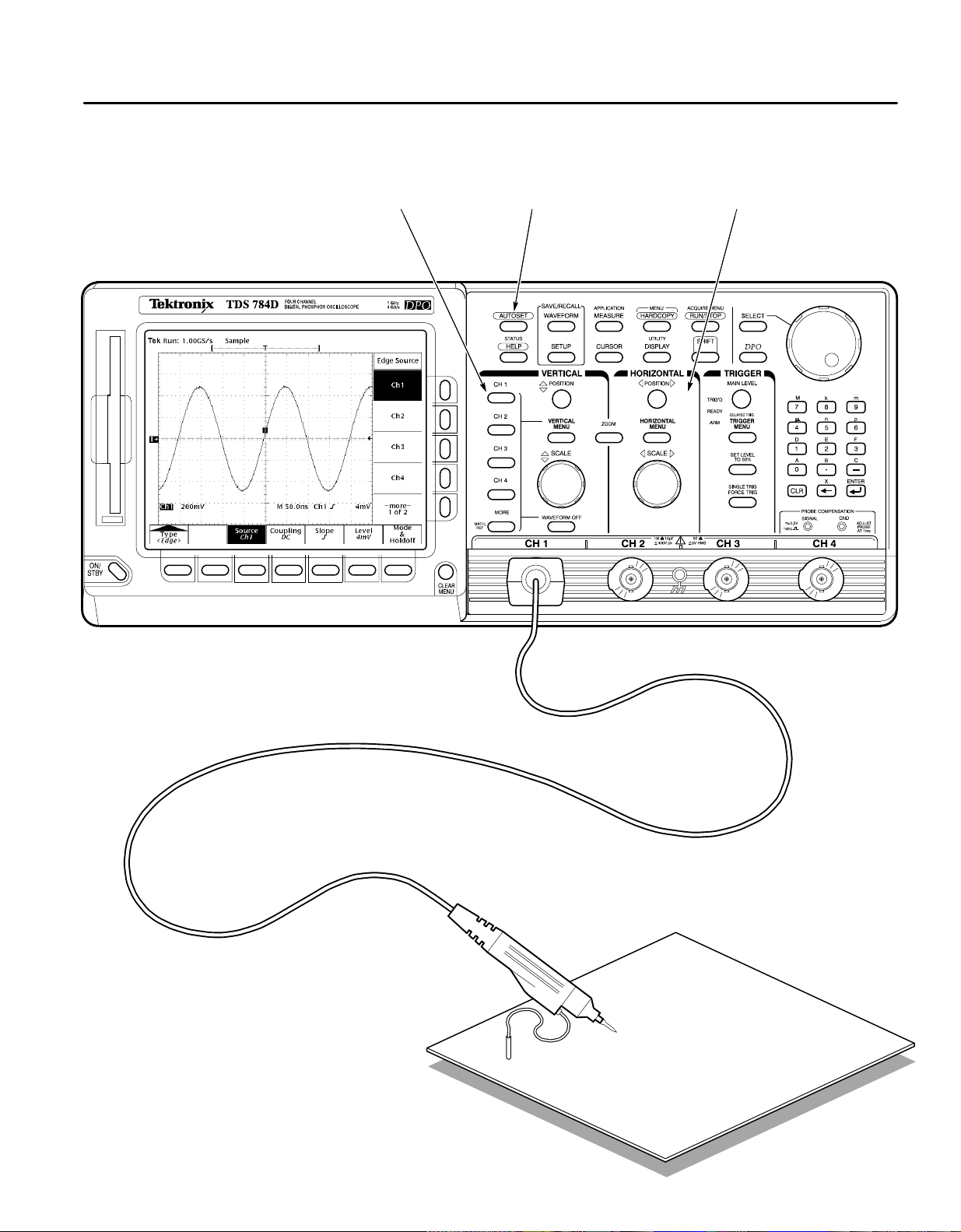
To Display a Waveform:
1234
Attach a probe to CH 1
and hook the probe to your
signal.
Press
CH 1.
Press
AUTOSET.
Adjust VERTICAL and HORIZONTAL
POSITION and SCALE.
Copyright E Tektronix, Inc., 1998. Printed in U.S.A.
Device under test

To Set Up Using a Menu:
1
Press any of the front panel menu buttons.
2
Select an item from the main (bottom) menu.
Use SHIFT for
the alternate
(blue) menus.
3
Select an item from the side menu, if displayed.
4
Adjust menu item values using the general purpose
knob or by entering numbers on the keypad.
The readout indicates the
value that you can adjust
with the general purpose
knob or keypad.
Adjustable menu item value
General purpose knob
Keypad
End your entry by
pressing ENTER ( ).

To Select a Trigger:
1
Press TRIGGER MENU.
2
Select a trigger type or parameter from the
main menu.
This symbol
indicates a
pop-up menu
Set TRIGGER MAIN LEVEL.
3
Trigger Selections
TYPE
<Edge>
Select any one of
Ch 1 thru Ch 4,
Line, or DC Aux
Positive
Negative
Define levels High,
Low, or Don’t Care
for Ch 1 thru Ch 4
(On some models, Ax 1 & Ax 2 replace Ch 3 & Ch 4)
TYPE
<Logic>
CLASS
<Pattern>
AND
OR
NAND
NOR
CLASS
<State>
Define levels High,
Low, or Don’t Care
for Ch 1 thru Ch 3
Select edge for the
clock (always Ch 4)
AND
OR
NAND
NOR
CLASS
<Setup/Hold>
Select one of
Ch 1 thru Ch 4 as
the data source
Do not select the
same channel used
as the clock source
Select one of
Ch 1 thru Ch 4 as
the clock source
Select the clock
Clock Source
edge
Do not select the
same channel used
as the data source
“T” shows the
trigger position
Press to display the pop-up menus
Press again to make a selection
A pop-up selection changes the other main
menu items
Arrow shows
the trigger level
Title of the
side menu
Removes the
menus from
the screen
Level
Level Slope Source
Set level or select
preset level based
on TTL or ECL logic
DC
Coupling
AC
HF
Reject
LF
Reject
Noise Rej (DC
Low Sensitivity)
Set a threshold
level for each of
Ch 1 thru Ch 4
Set Thresholds Define Logic Define InputsTrigger When
Goes TRUE
Goes FALSE
TRUE for
less than
TRUE for
more than
1
Qualification by time
Set a threshold
level for each of
the pattern
channels, Ch 1
thru Ch 3, and
the clock, Ch 4.
Goes TRUE
Trigger When Set Thresholds Define Logic Define Inputs
Goes FALSE
1
1
Clock
Levels Data SourceSetup/Hold Times
Data
Set levels or select
preset levels based
on TTL or ECL logic
Select and set the
Setup Time
Select and set the
Hold Time

CLASS
<Glitch>
CLASS
<Runt>
TYPE
<Pulse>
CLASS
<Width>
CLASS
<Slew Rate>
CLASS
<Time Out>
TYPE
<Video>
(Optional)
TYPE
<Comm>
(Optional)
Select any one of
Ch 1 thru Ch 4
Source
Positive
Negative
Polarity & Width
Either
Select any one of
Ch 1 thru Ch 4
SourceTrigger When
Positive
Polarity
Negative
Either
Width
Level Level
Runt
Upper
Thresholds
Runt
Lower
Select any one of
Ch 1 thru Ch 4
Positive
Polarity Source
Negative
Select any one of
Ch 1 thru Ch 4
SourceTrigger When
Positive
Polarity
Negative
Either
High
Thresholds
Low
Select any one of
Ch 1 thru Ch 4
Stays
High
Polarity
Stays
Low
Either
Level
Level SourceTime
Select any one of
Ch 1 thru Ch 4
Source
Negative Sync
Positive Sync
Sync Polarity
Set video field
and line number
Select any one of
Ch 1 thru Ch 4
Source
AMI
CMI
NRZ
Level
High
Low
Set level or select
preset level based
on TTL or ECL logic
Accept
OFF
Glitch
ON
Reject
Glitch
Glitch (Filter) Level
Set levels or select
preset levels based
on TTL or ECL logic
Select trigger
when any runt
occurs or ...
Select triggering
when a runt wider than specified
2
occurs
2
Qualification by width
Set level or select
preset level based
on TTL or ECL logic
Within
Limits
Out of
Trigger When Level
Limits
Set Lower and
Upper Limits
Set levels or select
preset levels based
on TTL or ECL logic
Faster
Slower
Delta
Time
Select faster than
or slower than and
set delta time
The oscilloscope
computes the slew
rate readout from
the delta time and
thresholds settings
Set level or select
preset level based
on TTL or ECL logic
Select and set
the Timeout Time
NTSC
Standard Field/Line
PAL
HDTV
FlexFmt
Set level or select
preset levels
DS<x>
E<x>
Standard Level/Threshold Code
FC<x>
OC<x>
STS-<x>
STM<x>
FDDI
4:2:2
4fsc NTSC
<x>Base-T
Gigabit
Ethernet
Custom

To Choose an Acquisition Mode:
1
Press SHIFT, and then press ACQUIRE MENU.
Press Mode in the main menu.
2
3
From the side menu, select an acquisition mode that will
serve your application.

How the Acquisition Modes Work:
Incoming
signal
Samples acquired for
each waveform data
point interval
Acquisition mode
processes samples
Sample
Uses first sample in interval
Displayed
data point
Waveform
drawn on CRT
Use for fastest acquisition rate.
Sample is the default mode.
Use to reveal aliasing and for
glitch detection.
Single
waveform
acquisition
Multiple
waveform
acquisitions
Peak Detect
Uses highest and lowest
samples in interval
Not Available on TDS 600C
Hi Res
Calculates average of
samples in interval
Envelope
Uses highest and lowest
samples over many acquisitions
Average
Peak Detect provides the
benefits of enveloping with
speed of single acquisition.
Use to reduce apparent noise.
Hi Res provides the benefits of
averaging with the speed of
single acquisition.
Use to reveal the noise band
around the signal.
Use to reduce apparent noise in
a repetitive signal.
Calculates average value
over many acquisitions

To Display Help On Screen:
1
Press HELP.
2
To Take Measurements With Cursors:
Now turn any knob or press any button and read a
description of it on the display . Press HELP again to
exit help.
Press CURSOR. Press Function in the main menu.
12
Move the cursor with the general purpose knob. Press
Select from the side menu.
3
Measures voltage
Measures time
Measures voltage at time
4
SELECT to switch between the cursors. Press SHIFT
to speed up/slow down the cursor movement.

To Take Measurements Automatically:
12
Press MEASURE.
34
Select up to four measurements.
Press Select Measrmnt or Snapshot in the main menu.
Press CLEAR MENU to move the measurement
readouts away from the graticule.
Automated Measurement Selections
Period
Frequency
Positive
Width
Negative
Width
—more—
1 of 8
Rise Time
Fall Time
Positive
Duty Cycle
Negative
Duty Cycle
—more—
2 of 8
Delay
Phase
Burst Width
—more—
3 of 8
High
Low
Max
Min
—more—
4 of 8
Select
Measurement
Amplitude
Overshoot
Overshoot
Pk–Pk
Positive
Negative
—more—
5 of 8
Mean
Cycle Mean
RMS
Cycle RMS
—more—
6 of 8
Area
Cycle Area
—more—
7 of 8
Extinction
Ratio
Extinction %
(FDDI)
Extinction dB
(SONET)
Mean dBm
(Average
Optical
Power)
—more—
8 of 8

To Save a Hardcopy to the File System:
12
Press SHIFT, and then press HARDCOPY.
34
Press Port in the main menu, press File in the side
menu, and then press CLEAR MENU.
Disk drive
Press Format in the main menu, and select a hardcopy
format from the side menu.
Press HARDCOPY anytime to save a copy of the current
screen to a unique file in the oscilloscope file system.
To Perform Other File System Operations:
H Press SA VE/RECALL WAVEFORM, and use the menu buttons to save a waveform to a file or recall it from a file.
H Press SA VE/RECALL SETUP, and use the menu buttons to save a setup to a file or recall it from a file.
H Press File Utilities in the Save/Recall Waveform, Save/Recall Setup, or Hardcopy menus to access utilities that create
directories, copy files, and do other operations in the oscilloscope file system.

To Preview a Waveform:
1
Press ZOOM.
2
Press Mode in the main menu. Then press Preview in the side menu to turn on Dual Window Zoom.
Upper graticule zooms the boxed area
on the selected waveform.
Lower graticule displays the selected waveform
unzoomed with the zoomed area in box.
3
Use the Selected Graticule menu to select the upper or lower waveform. Use the vertical and horizontal knobs
to adjust the waveform in the graticule you select.
To Capture Infrequent Events (TDS 500D & 700D Models):
Press DPO to toggle between DPO and Normal waveform capture
rates.
When in DPO mode:
H Waveforms displayed are updated thousands of times
faster than normal.
H Very brief changes in waveforms are captured.
H Certain features, such as Limit Testing, Math Waveforms, Zoom, and
record lengths longer than 500 points, are not available.
 Loading...