

Page 1

Instructions
TDS6UP, TDS7UP, and CSA7UP Option CPU
Upgrade Kit
071-1244-01
Warning
The servicing instructions are for use by qualified
personnel only. To avoid personal injury, do not
perform any servicing unless you are qualified to
do so. Refer to all safety summaries prior to
performing service.
www.tektronix.com
*P071124401*
071124401
Page 2

Copyright © Tektronix, Inc. All rights reserved.
Tektronix products are covered by U.S. and foreign patents, issued and pending. Information in this publication supercedes
that in all previously published material. Specifications and price change privileges reserved.
Tektronix, Inc., P.O. Box 500, Beaverton, OR 97077
TEKTRONIX and TEK are registered tradem arks of Tektronix, Inc.
Page 3

Service Safety Summary
Only qualified personnel should perform service procedures. Read this Service
Safety Summary and the General Safety Summary in the product service manual
or the instruction manual.
Do Not Service Alone. Do not perform internal service or adjustments of this
product unless another person capable of rendering first aid and resuscitation is
present.
Disconnect Power. To avoid electric shock, switch off the instrument power, then
disconnect the power cord from the mains power.
Use Care When Servicing With Power On. Dangerous voltages or currents may
exist in this product. Disconnect power, remove battery (if applicable), and
disconnect test leads before removing protective panels, soldering, or replacing
components.
To avoid electric shock, do not touch exposed connections.
TDS6UP, TDS7UP, and CSA7UP Option CPU Upgrade Kit
1
Page 4

Service Safety Summary
2
TDS6UP, TDS7UP, and CSA7UP Option CPU Upgrade Kit
Page 5

Kit Description
This document supports upgrading the NLX CPU board and microprocessor. To
upgrade your NLX CPU board and microprocessor perform each of the
following procedures in order.
Products
TDS6000 Series All serial numbers
TDS7000 Series All serial numbers
CSA7000 Series All serial numbers
Minimum Tool and Equipment List
Table 1: Equipment list
Required tools and equipment Part number
Screwdriver handle 620-440
T-20 Torx tip 640-250
T-15 Torx tip 640-247
1
/
inch flat-bladed screwdriver
8
#0 Phillips screwdriver Standard tool
3
/
inch open-end wrench
16
Standard tool
Standard tool
TDS6UP, TDS7UP, and CSA7UP Option CPU Upgrade Kit
3
Page 6

Kit Description
Kit Parts List
Circuit/figure
number
1 1ea 650--4562--00 COMPONENT KIT;MOTHERBOARD/
2 1ea 407--4880--01 BRACKET; CD--ROM, REAR DRIVE BAY
1
Quantity Part number Description
MICROPROCESSOR UPGRADE;TDS6/7UP
OPTION CPU
CHASSIS, 0.035 CRS
1ea 020--2349--XX SOFTWARE KIT; LICENSE CERTIFICATE,O/S
EASY RESTORE,CERTIFICATE AUTHENTICITY,WIN98 RESTORE CD
1ea 063-3645-01 SOFTWARE; BIOS UPDATE CD
Figure 1: CPU upgrade kit parts
2
4
TDS6UP, TDS7UP, and CSA7UP Option CPU Upgrade Kit
Page 7

Installation Instructions
This section contains all procedures needed to install TDS6UP, TDS7UP, or
CSA7UP Option CPU in the TDS6000, TDS7000, and CSA7000 Series
instruments.
These instructions are for personnel who are familiar with servicing the product.
If you need further details for disassembling or reassembling the product, refer to
the appropriate product manual. Contact your nearest Tektronix Service Center
or Tektronix Factory Service for installation assistance.
CAUTION. To prevent static discharge damage, service the product only in a
static-free environment. Observe standard handling precautions for static-sensitive devices while installing this kit. Always wear a grounded wrist strap,
grounded foot strap, and static resistant apparel while installing this kit.
Remove
Preparation
This section contains procedures for removal and installation of all mechanical
and electrical modules.
H Line Cord
H Trim (all)
H Bottom cover
H Left and Right covers
H NLX board
H Rear chassis
H CD drive bracket
WARNING. Before doing this or any other procedure in this manual, read the
Safety Summary found at the beginning of this manual.
TDS6UP, TDS7UP, and CSA7UP Option CPU Upgrade Kit
5
Page 8
Installation Instructions
This subsection contains the following items:
H This preparatory information that you need to properly do the procedures
that follow.
H List of tools required to remove and disassemble all modules.
H Procedures for removal and reinstallation of the electrical and mechanical
modules.
WARNING. Before doing any procedure in this subsection, disconnect the pow er
cord from the line voltage source. Failure to do so could cause serious injury or
death.
NOTE. Read Equipment list for a list of the tools needed to remove and install
modules in this instrument. See Table 1, on page 3.
Equipment Required. Most modules in the TDS6000, TDS7000, and CSA7000
Series Instruments can be removed with a screwdriver handle mounted with a
size T-15, Torx screwdriver tip. Use this tool whenever a procedure step instructs
you to remove or install a screw unless a different size screwdriver is specified in
that step. All equipment required to remove and reinstall each module is listed in
the first step of the procedure.
Procedures for External Modules
The following procedures are found here and are listed in the order presented.
H Line Cord
H Trim (all)
H Bottom cover
H Left and Right covers
6
TDS6UP, TDS7UP, and CSA7UP Option CPU Upgrade Kit
Page 9

Installation Instructions
Line Cord
1. Assemble equipment and locate modules to be removed: Locate the power
switch and AC power cord connector in Figure 2 on page 7.
2. The instrument has a built-in soft power-off function that safely powers off
the instrument when you press the On/Standby switch.
3. Power off the rear panel power switch before servicing the power cord.
4. Orient the instrument: Set the instrument so that the bottom is down on the
work surface and the rear is facing you.
5. Remove line cord: Find the line cord on the rear cover. Pull the line cord
away to remove from the AC power connector.
6. Reinstallation: Do in reverse step 5 to reinstall the line cord.
Power
switch
Line fuses
Figure 2: Line cord removal
TDS6UP, TDS7UP, and CSA7UP Option CPU Upgrade Kit
AC power cord
connector
AC power
cord
Line fuse
holder
7
Page 10

Installation Instructions
Trim and Carrying Handle
1. Locate module to be removed: Locate the Trim in the locator diagram. See
Figure3,onpage9.
2. Remove the front panel trim: Use F igure 3 on page 9 as a guide.
a. To prevent the power button from falling out of the front panel trim,
place a piece of tape over the button.
b. Grasp the trim ring by the top edge and pull toward you to detach the
three plastic snaps. (Alternatively, you can use a flat-bladed screwdriver
or other small prying tool to help you detach the snaps.)
c. Swing the bottom of the ring upward and off the front panel.
3. Remove the acquisition trim: Use Figure 3 on page 9 as a guide.
a. Remove the three T-15 Torx screws that secure the acquisition trim to
the instrument.
b. Remove the acquisition trim from the instrument.
4. Remove the top cover trim: Use Figure 3 on page 9 as a guide.
a. Remove the accessory pouch; it snaps off.
b. Remove the four T-15 Torx screws that secure the top cover trim to the
instrument. The T-15 Torx screws also secure the snap studs to the top
cover.
c. Remove the top cover trim from the instrument.
5. Remove the carrying handle and the right/left side trim panels: Use Figure 3
on page 9 as a guide.
a. Remove the T-20 Torx screws that secure the handle to the instrument.
Remove the handle from the instrument.
b. Slide the side trim panels towards the rear of the instrument allowing the
tabs to clear the cover openings, and then pull out to remove the panels
from the instrument.
6. Reinstallation: Do in reverse steps 2 through 5 to reinstall the appropriate
trim.
8
TDS6UP, TDS7UP, and CSA7UP Option CPU Upgrade Kit
Page 11

Left side trim
Installation Instructions
Snap stud (4)
T-15 Torx screw (4)
Top cover trim
Right side trim
Front panel trim
Figure 3: Trim removal
Acquisition trim
T-15 Torx
screw (3)
Soldering aid
To remove the trim ring, slide the flat
end of a soldering aid into the side
slot on the trim ring. Press in, and
then lift up to hook it underneath.
Then pry it up.
Carrying handle
T-20 Torx screw (2)
TDS6UP, TDS7UP, and CSA7UP Option CPU Upgrade Kit
9
Page 12

Installation Instructions
Bottom Cover
1. Remove the bottom cover: See Figure 4 on page 10.
2. Orient the instrument: Set the instrument so the top is down on the work
surface and the bottom is facing you.
a. Remove the four T-15 Torx screws that secure the bottom cover to the
instrument.
b. Remove the bottom cover from the instrument.
3. Reinstallation: Do steps a and b in reverse to reinstall the bottom cover.
10
Bottom cover
T-15 Torx
screw (4)
Figure 4: Bottom cover removal
TDS6UP, TDS7UP, and CSA7UP Option CPU Upgrade Kit
Page 13

Installation Instructions
Covers
1. Remove the left and right covers: See Figures 5 and 6 on pages 12 and 13.
H Trim (all)
H Bottom cover
2. Orient the instrument: Set the instrument so that its rear is on the work
surface and the front of the instrument is facing you.
NOTE. All mounting screw holes are indicated by a star etched around the
mounting hole.
a. Remove the eleven T-15 Torx screws that secure the covers to the top
and both sides of the chassis.
b. Remove the seven T-15 Torx screws that secure the covers to the bottom
of the chassis.
c. Pull the bottom-right cover down and slide to the right to remove from
the instrument. Pull the top-left cover upward and slide to the left to
remove from the instrument.
CAUTION. Take care not to bind or snag the covers on the internal cabling of the
instrument as you remove or install.
3. Reinstallation: Do in reverse steps a through c to reinstall the cabinet covers.
TDS6UP, TDS7UP, and CSA7UP Option CPU Upgrade Kit
11
Page 14

Installation Instructions
All left and right cover
mounting holes are
indicated as shown.
Left side cover
T-15 Torx
screw (11)
Right side cover
Figure 5: Cover removal
12
TDS6UP, TDS7UP, and CSA7UP Option CPU Upgrade Kit
Page 15

Installation Instructions
Left side cover
Right side cover
T-15 Torx screw
(7)
Figure 6: Cover removal
TDS6UP, TDS7UP, and CSA7UP Option CPU Upgrade Kit
13
Page 16

Installation Instructions
Procedures for Internal Modules
The following procedures are found here and are listed in the order presented.
H NLX board
H CD drive bracket
NLX Board
1. Locate module to be removed: Locate the NLX Board in the locator diagram
Internal Modules, Figure 7, on page 15. Additional modules to be removed:
WARNING. Remove the line cord before removing the covers from the instrument.
H Trim (all)
H Bottom cover
H Left and Right covers
14
TDS6UP, TDS7UP, and CSA7UP Option CPU Upgrade Kit
Page 17

Fan assembly
Installation Instructions
Hard drive
CD drive
CD drive Interface
board
Microprocessor,
fan and heat sink
NLX board
Riser board
Floppy disk drive
Display adapter board
Power flex circuit
Display module assembly
Figure 7: Internal modules
Power PC (PPC)
board
Low-voltage power
supply assembly
Acquisition board
Front panel
Front panel
assembly
board
Front panel
keypad
distribution
Front
distribution
board
Rear
board
PA bus
board
2. Remove the NLX Board assembly: See Figure 8 on page 17.
3. Orient the instrument: Set the instrument so that the bottom is down on the
work surface and the top panel is facing you.
a. Remove the two T-15 Torx screws that secure the floppy disk drive
assembly into the front chassis.
TDS6UP, TDS7UP, and CSA7UP Option CPU Upgrade Kit
15
Page 18

Installation Instructions
b. Slide the floppy drive assembly, with cable attached, out toward the rear
of the instrument. Place floppy drive assembly on top of the hard/CD
drive bracket.
c. Remove the five T-15 Torx screws that secure NLX board assembly to
the chassis.
d. Remove the five T-15 Torx screws that secure NLX board assembly to
the rear chassis.
e. Grasp the front edge of the NLX board assembly and pull up on the
assembly to disconnect the Riser Adapter from the Processor board edge
connector.
f. Remove the NLX board assembly from the instrument.
16
TDS6UP, TDS7UP, and CSA7UP Option CPU Upgrade Kit
Page 19

Place floppy drive assembly on
top of hard/CD drive bracket
NLX board
assembly
Riser adapter
Leave floppy drive
cable attached
Installation Instructions
Hard/CD drive
bracket
board
Remove floppy
drive assembly
from front chassis
Processor board
edge connector
Figure 8: NLX assembly removal
4. Remove the Riser Adapter and NLX Boards: See Figure 9 on page 18.
a. Remove the screws that secure the hard/CD drive bracket to the NLX
board assembly.
b. Remove the two T-15 Torx screws that secure Riser Adapter board to the
NLX support bracket.
c. Disconnect the ribbon cable connectors from the floppy drive, hard
drive, and CD drive.
TDS6UP, TDS7UP, and CSA7UP Option CPU Upgrade Kit
17
Page 20
Installation Instructions
d. Remove the floppy drive assembly from the NLX board assembly.
e. Grasp the Riser board and pull it straight out to disconnect J510 edge
card connector from the NLX board. Remove the Riser Adapter board
from the NLX board assembly.
f. Remove the CD drive from the NLX board assembly. Discard the NLX
board assembly.
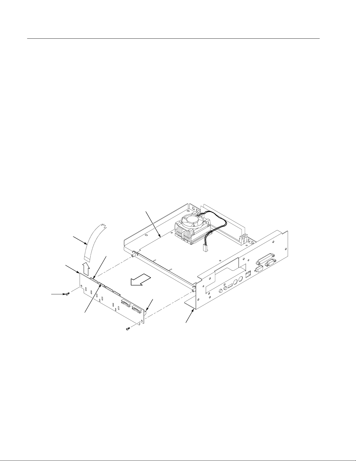
5. Remove the CD Drive bracket and Rom interface board: SeeFigure10on
page 19.
a. Remove the four #0 Phillips screws that secure the bracket to the CD
Drive. Remove the CD Drive from the bracket.
b. Replace the CD Drive bracket with the one that came in your kit.
6. Reinstallation: Do in reverse steps 3 and 4 to reinstall the NLX board
assembly.
NLX board
Floppy drive
cable
Riser adapter
board
T--15 Torx
screw (2)
CD drive cable
connector
Hard drive
cable
connector
Figure 9: Riser adapter and NLX board removal
J510
NLX support
bracket
18
TDS6UP, TDS7UP, and CSA7UP Option CPU Upgrade Kit
Page 21

Disconnect
J230 CD drive
ribbon cable
CD drive
interface board
CD drive
ribbon cable
Installation Instructions
CD drive
#0 Phillips
screw (4)
CD drive bracket
T--15 Torxdrive
screw (2)
Figure 10: CD drive and bracket removal
Install
Reassemble and Install
TDS6UP, TDS7UP, and CSA7UP Option CPU Upgrade Kit
This section provides instructions for reassembly of the instrument and
reinstalling the operating software.
1. Reinstall the CD drive, riser adapter, and NLX board assembly (refer to page
18).
2. Reinstall left and right covers (refer to page 11).
3. Reinstall the bottom cover (refer to page 10).
19
Page 22

Installation Instructions
4. Reinstall the trim and carrying handle (refer to page 8). Make sure that the
interlock tabs and the standby power button are correctly positioned when
installing the trim.
5. Reinstall the line cord (refer to page 7).
Install the Operating
System Software
Verify Operation
After you install the NLX board assembly, you need to reinstall the operating
software provided in this kit.
Use the following procedure to install the software:
1. Install the new Windows 2000 Operating system CD. Follow the instructions
provided with the Windows 2000 Operating system CD.
2. To update the instrument BIOS, follow the instructions in the
Instructions.txt file on the BIOS Update CD.
3. Install the TDS6000 or TDS7000 Series Product software CD. Follow the
instructions provided with the Product software CD.
4. Install the Applications software CD. Follow the instructions provided with
the Applications software CD.
This section contains instructions to check that the additional memory that you
installed is functioning.
1. Connect the power cord to the rear panel of the instrument and then to the
mains power.
20
2. Switch the power button to the On position.
3. Push the Standby/On button to power on the instrument.
4. After the instrument application opens, select Minimize from the File menu
to minimize the application.
5. Right--click the My Computer icon.
6. Select Properties from the pop-up menu.
7. Select the Performance tab in the Properties dialog box.
8. Check that Memory lists the correct amount of RAM.
9. Click the TekScope button on the Windows toolbar to display the instrument
application.
This completes the verification of the NLX board assembly in your instrument.
g End of document g
TDS6UP, TDS7UP, and CSA7UP Option CPU Upgrade Kit
 Loading...