

Tektronix TDS7054, TDS7254, TDS7404, TDS7104, TDS6604 Reference manual
...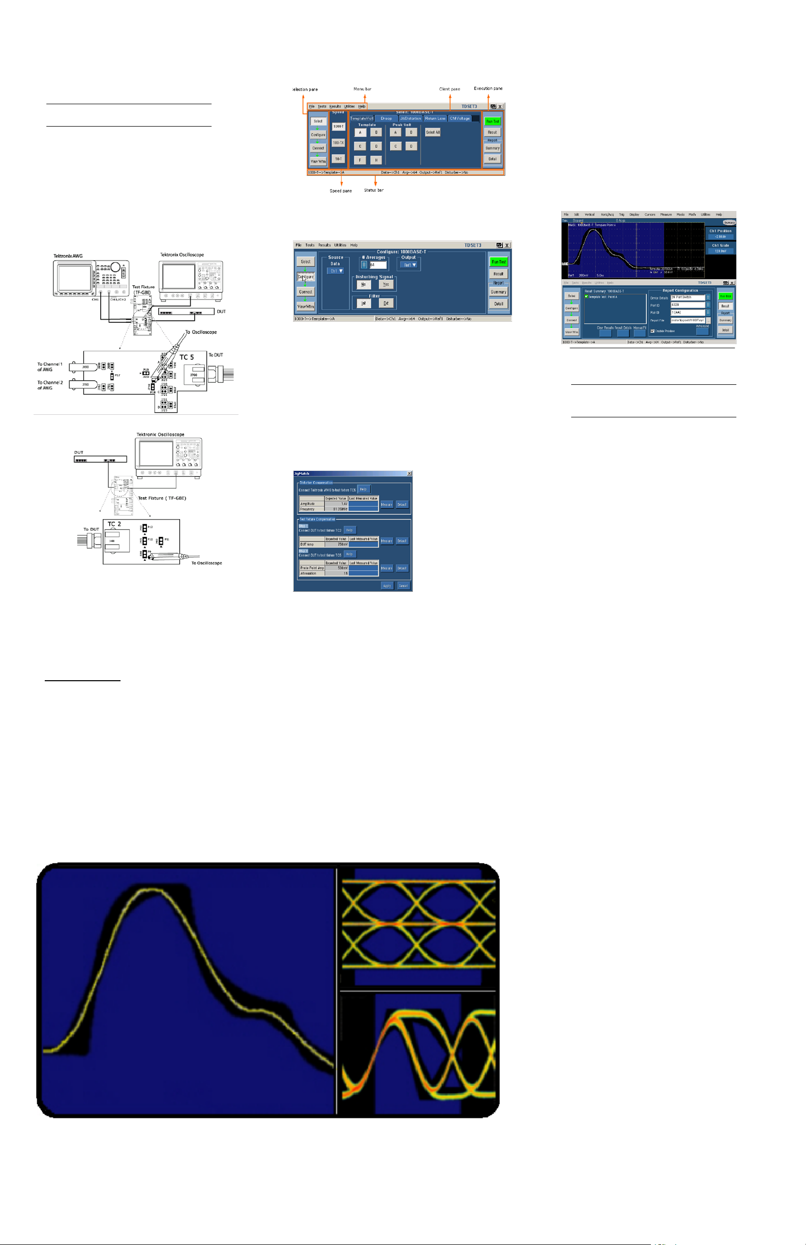
Getting Started with TDSET3
You can use this side of the Quick Reference Card to get
started with testing the Ethernet’s physical layerfor
1000Base-T Templates. The other side contains a complete
menu tree for the TDSET3 application.
NOTE. For complete operating instructions,
refer to the application Online Help.
TDSET3 Ethernet Compliance Test Software enables
unprecendented efficiencyby providing a comprehensive
rangeoftests, including Return Loss.
Testing 1000Base-T Templates
Follow these steps:
1. Connectthe probes to the Device Under Test (DUT).
For example, the testsetup for 1000Base-T Template is
shown below.
WithDisturbingSignal
3. Click1000-T in the Speed pane or select Tests > Select
> 1000BASE-T fromthemenu bar.
4. From the Template/Volt tab, click Select All. You can
also select one template at a time to test.
5. ClicktheConfigure button from the Selection pane, or
select Tests > Configurefrom the menu bar tochange
the configuration settings.
9. To measure the disturbing signal, connect the Tektronix
AWG to the TC5 area ofthe test fixture and click
Measure.
10. To compensate for non-linearities in the test fixture,
connect the DUT to the TC2 area of the test fixture and
click Measure. This measures the DUT Amplitude.
11. Next,tomeasure theProbe Point Amplitudeand
Attenuation, connect the DUT to the TC5 area of the test
fixture, and click Measure. Click Apply.
12. Click View Wfm from the Selection pane. If the
acquired waveformlookssimilarto the one displayed by
TDSET3, continue to step 13. If thewaveforms do not
match, check the connection and the configuration.
Ensure that the first pulse is rising.
13. Click Run Test in the Execution pane. The application
displays the resulting waveform and the results.
WithoutDisturbingSignal
2. Select File > Run Application > Ethernet Compliance
TestSoftware in the oscilloscope menu bar.
6. Select the data source, number of averages, filter, and the
reference waveform to store the processed waveform.
7. To test Te mplates with Disturbing Signal, select
Disturbing Signal as Yes.TheTektronix AWG
waveform files are available at
C:\TekApplication\TDSET3\AWG Waveforms. To test
Templateswithoutdisturbing signal, selectDisturbing
Signalas No and skip steps8 through 11.
8. Click Connect from the Selection pane and click the
JigMatch button. Select Help and connect accordingly.
To compensate for non-linearities in the disturbing
signaland the testfixture, useJigMatch (steps 9 through
11).Otherwisegotostep12.
14. Click Result in the Execution pane to view the result
summary and details.
NOTE. To manually fit thewaveform intothe
mask, select Result in the Execution pane and
click theManualFit button.
15. ClickResult from theExecution pane to configure the
report. Enter the Device Details, Port ID, Pair ID, and
the Report File. You can specify that you want to
automatically preview the report.
16. Select Summary from the Execution pane to generate
and save a brief .csv report at
C:\TekApplications\TDSET3\ReportGenerator\Reports.
17. Click Detail from the Execution pane to generate and
save a detailed .rpt report at
C:\TekApplications\TDSET3\ReportGenerator\Reports.
18. If you wantto customize the report format, select
Utilities > Report Generator. In the Generate Report tab,
select the template and click the Generate button to post
the test data to the template.
For up-to-date information on Tektronix oscilloscope
solutions for Ethernet Compliance TestSoftware, access
the www.tektronix.com
TDSET3 OrderingInformation
This application supports theTDS5000B,TDS6000/B,
TDS/CSA7000B, and TDS/CSA7000Series of
oscilloscopes. Refer to the Optional Applications Software
on Windows-Based Oscilloscopes Installation Manual for a
listofspecificmodels. The applications CD includes a PDF
file of the installation manual.
Web page.
If you orderOption ET3 along with TDS5000B,
TDS6000/B, TDS/CSA7000B,and TDS/CSA7000:
H Ethernet Compliance Test Software is installed and
enabled
To orderan upgradeforan existing oscilloscope:
H Order TDS5BUP -- Opt. ET3
H OrderTDS6UP -- Opt. ET3
H Order TDS6BUP -- Opt. ET3
H Order TDS7BUP -- Opt. ET3
H OrderTDS7UP -- Opt. ET3
H Order CSA7BUP -- Opt. ET3
H OrderCSA7UP -- Opt. ET3
Recommended Accessories
H Ethernet Test Fixture from Crescent Heart Software
(www.c--h--s.com)
TDSET3
Ethernet Compliance Test Software
Reference
www.tektronix.com
*P071139602*
071139603
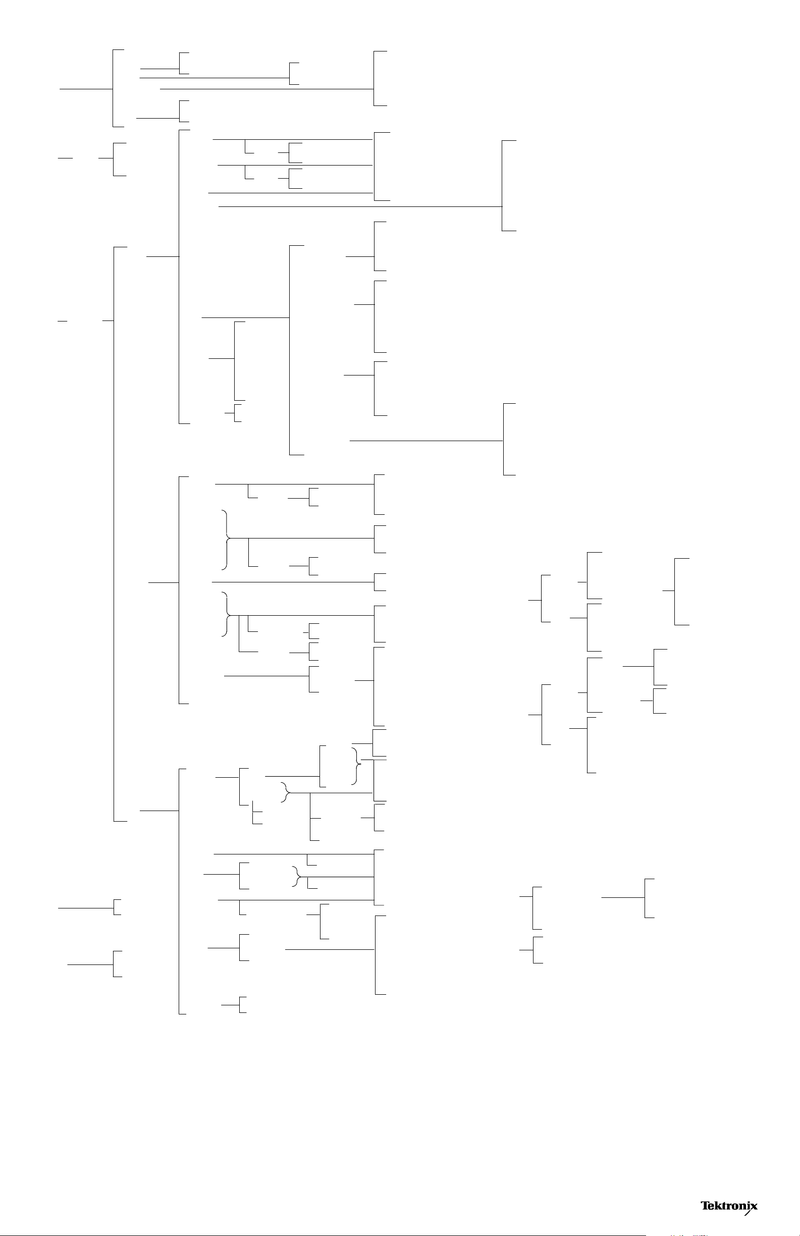
TDSET3 Menu Tree
File
Recall Default
Recall
Save
Preferences
Minimize
Hide
Exit
File Browser
Open | Cancel
Restore Oscilloscope Settings
Yes | No| Cancel
File Browser
Save | Cancel
Show Ref Overwrite Warning
Show Math Overwrite Warning
Show 10Base-T Template User Control
Show 1000Base-T Distortion User Control
Show 10Base-T Jitter User Control
Tes ts
Tes ts
Select
Configure
1000BaseT
100 BaseTX
10BaseT
1000-T
Tem plate
Peak Volt
Droop
Distortion
Jitter
Return
Loss
CM Voltage
Filter
Filter
Probe:P1
Probe:P2
Pair ID
Load
# Averages
Smooth(0-10)
Output Wfm
AWG Series
Source
Int
Ext
Int
Ext
Master Filtered
Master Unfiltered
Slave Filtered
Slave Unfiltered
Source
# Averages
Output
Disturbing Signal
Source
Hysteresis
Clock Edge
TX_TCLK
Record Length
Source
Hysteresis
Clock Edge
TX_TCLK
Meas Type
Record Length
Source
Hysteresis
Clock Edge
TX_TCLK
Record Length
Source
# Averages
Output
TX_TCLK
Disturbing Signal
Hi Resolution
Low Pass Filter
Source
Hysteresis
Clock Edge
TX_TCLK
Meas Type
Record Length
100-TX
10-T
Tem plate
Output Volt
Amp Sym
Distortion
Overshoot
Jitter
Rise Time
Fall Time
R/F Sym
Return Loss
Tem plate
Polarity
Polarity
Pattern
Pulse Width
Polarity
MAU
TP_IDL
Link Pulse
Sequence
Test Options
Both|Pos|Neg
Both|Pos|Neg
Random| 0101
16ns | 80ns
Both|Pos|Neg
Transmitter
Receiver
Both
Normal
Inverted
Acquisition
Source
Mask Scale
Mask Setup
Source
Acquisition
Source
Source
AWG Series
Acquisition
Probe:P1
Probe:P1
Probe:P2
Probe:P2
Pair ID
Pair ID
Load
Load
# Averages
# Averages
Smooth(0-10)
Smooth(0-10)
Output Wfm
Output Wfm
AWG Series
MAU Selection
Source
Mask Setup
Sample
Average
Reports
Connect
Summary
Details
JigMatch
Return
Loss
Clear Results Result
Details
Manual Fit
Report Configuration
Locate Hits
Flash Hits
Show Seg
Close
Disturber
Compensation
Tes t Fi xture
Compensation
Open
Short
Load
New Cal
Apply Cal
Device Details
Port ID
Pair ID
Report File
Enable Preview
Advanced
Amp
Freq
Phase
Amp DUT + Probe Amp
Atten
Tes ts
Results
View Wfm
Summary
Details
Diff Volt
Jitter
Harmonic
Return
Loss
CM Voltage
with Cable
without Cable
Harmonic Ones
Transmitter
Receiver
Source
100 Ωw/oTPM, Load1w/oTPM, Load2w/oTPM, 100 Ωw/TPM, Load1w/TPM, Load2w/TPM
Peak
MAU Selection
Output
# Averages
Time/Scale
Source
Acquisition
Probe:P1
Probe:P1
Probe:P2
Probe:P2
Pair ID
Pair ID
Load
Load
# Averages
# Averages
Smooth(0-10)
Smooth(0-10)
Output Wfm
Output Wfm
AWG Series
Utilities
Help
Report Generator
Enable Remote GPIB
Automate AWG
Help Topics
About Ethernet Compliance Test Software
Define Test Template
Define Report Layout
Generate Report
Copyright Tektronix,Inc.
 Loading...