

Page 1

Reference
TDS6000 Series
Digital Storage Oscilloscopes
071-7013-01
*P071701301*
071701301
Page 2
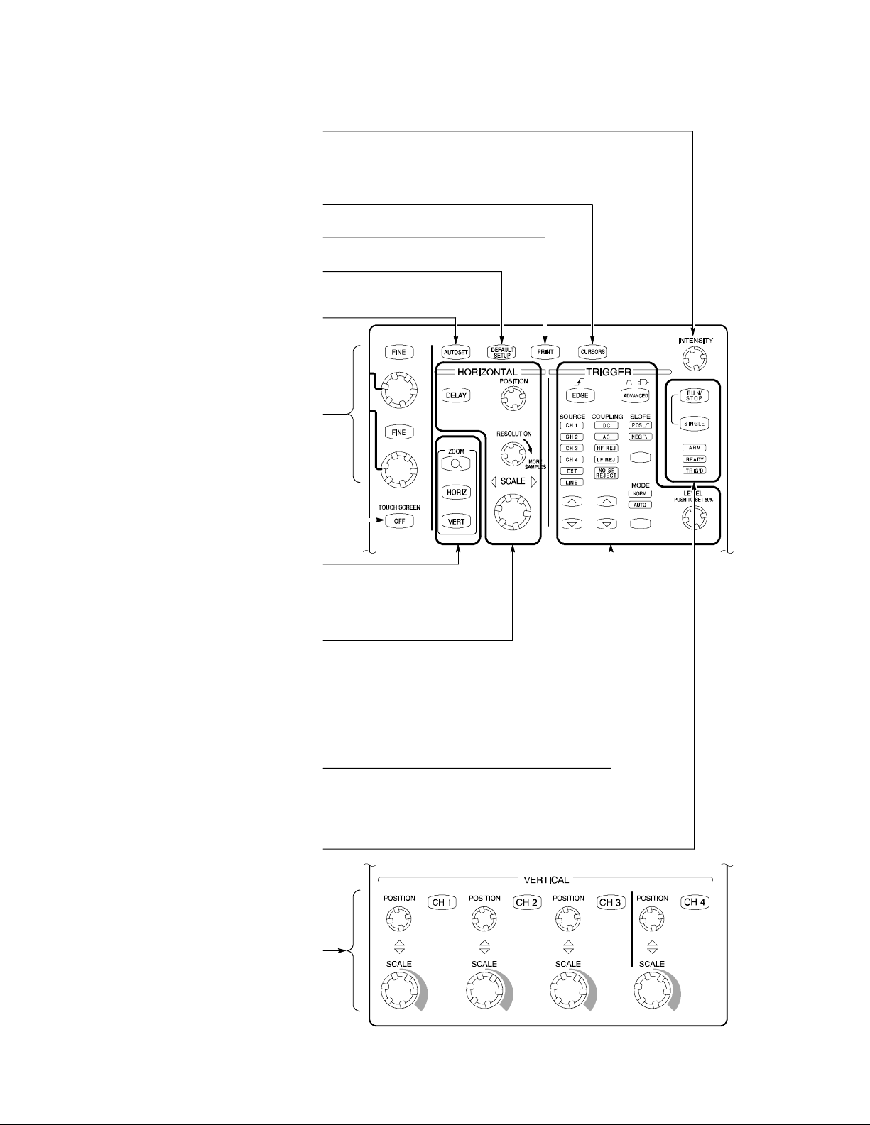
To Use the Front Panel
You can use the dedicated, front-panel knobs and buttons to do the most commonly performed operations.
Turn INTENSIT Y to adjust waveform intensity.
Push CURSORS to turn cursors on and off.
PRINT to make a hard copy.
Push
Push
DEFAULT SETUP to return settings to the
default values.
Push
AUTOSET to quickly set the vertical,
horizontal, and trigger controls for a
Use the multipurpose knobs to control
parameters selected from the screen interface.
FINE button to make small changes with
Push a
usable display.
a multipurpose knob.
Push to turn the touch screen on and off.
ZOOM to add a magnified graticule to the
Push
display. Push the HORIZ or VERT button to
select the axis that you want to magnify.
Use these knobs and buttons to set horizontal
SCALE and POSITION for the waveforms. Push
DELAY to turn on horizontal delay, and then
use POSITION to set the delay time. Adjust
RESOLUTION to change the number of
acquired points in the waveform.
Use these knobs and buttons to set the basic
trigger parameters. Push
ADVANCED to
display a menu of additional trigger functions.
Use these buttons to start and stop
acquisition or start a single acquisition
sequence. The ARM, READY, and TRIG’D
lights show the acquisition status.
Turn channel displays on and off, and adjust the
channel
POSITION and SCALE using dedicated
knobs and buttons.
Copyright E Tektronix, Inc. Beaverton, OR 97077
www.tektronix.com
Page 3
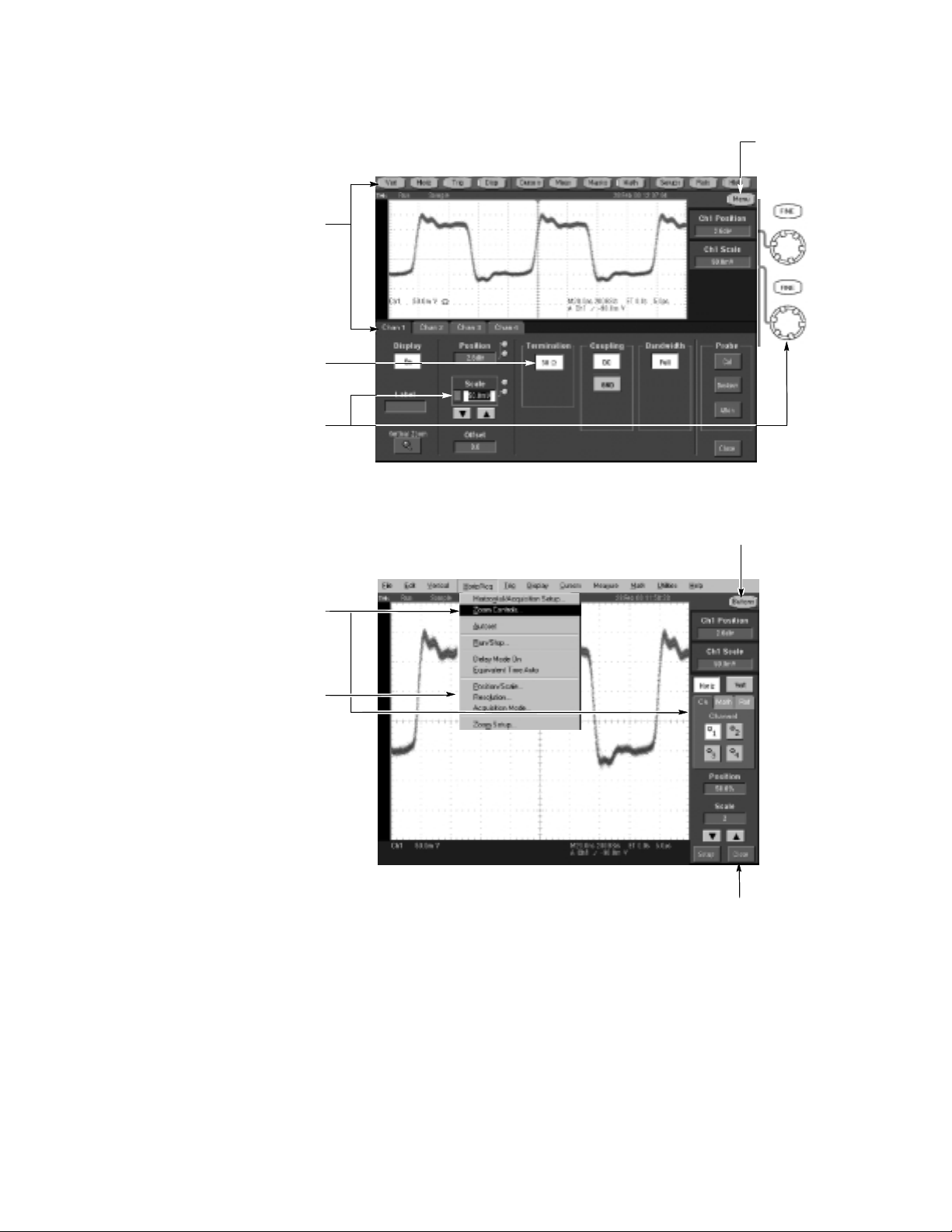
To Use the Screen Interface
You can control all oscilloscope functions except the power switch using only the screen interface.
Choose the Toolbar
Touch a button in the toolbar to display a
control window at the bottom of the displ ay.
Touch a screen control to change a setting.
Touch a numerical control to assign that control
to a multipurpose knob. Turn the mul tipurpose
knob to adjust the parameter value.
Touch here to
change to menu-bar
operation.
Touch here to change to
toolbar operation.
Or Choose the Menu Bar
Use some menu items to
display a control window at the
bottom or side of the display.
Use some menu items to
directly change settings.
Touch here to close a
control window.
More Operating Tips:
H Use the touch screen to control the oscilloscope when bench space is
unavailable, such as on a cart or in an equipment rack.
H Plug in a mouse and keyboard if you have the bench space to use them. You can
plug in a USB mouse or keyboard anytime, even while the oscilloscope is
running.
H Use the menu bar to access PC-related functions, such as Page Setup, Export,
and Copy.
Page 4
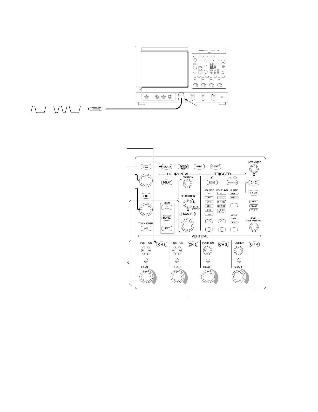
To Display a Waveform
Attach a probe to CH 1 and connect the probe
to your signal.
Push CH 1 if channel 1 is not
already displayed.
Push AUTOSET.
1
CH 1
2
3
Adjust VERTICAL and HORIZONTAL
POSITION
Adjust RESOLUTION to change the record
length and sample rate. You can acquire
more samples in the waveform to see more
detail or acquire fewer samples with a
and SCALE if necessary to
optimize the display.
faster update rate.
4
5 6
Adjust INTENSITY to change the
brightness, vector fill, and display
persistence of acquired points.
Page 5
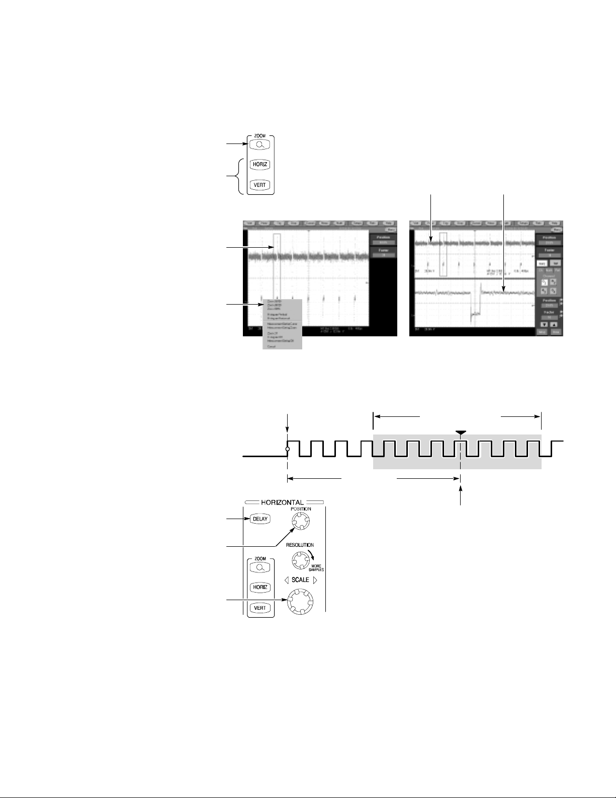
To See More Waveform Detail
Use Zoom
Push the ZOOM button to display a
zoom graticule.
Push the HORIZ button or the VERT button to
select the axis you want to magnify in the zoom
graticule. Use the multipurpose knobs to adjust
the zoomed waveform’s position and
magnification factor.
You can also set up a zoom graticule
from the screen interface. First touch and
drag across the segment of the waveform
that you want to see in greater det ail.
Then select a zoom graticule mode from the
drop-down list to magnify the highlighted
waveform segment.
Use Horizontal Delay
Use the Zoom function to magnify an acquisition vertically, horizontally, or in both
display dimensions.
graticule affect only the zoom display, not the actual acquired waveform.
POSITION or FACTOR changes that you make to the Zoom
1
2
Main graticule Zoom graticule
3
4
Use horizontal
the trigger location by a significant interval of time.
DELAY to acquire waveform detail in a region that is separated from
Push the front-panel DELAY button.
Adjust the delay time with the horizontal
POSITION control, or enter the delay time
in the control window.
Adjust the horizontal SCALE to acquire
the detail you need around the delay
expansion point.
Trigger point
Delay time
1
Acquired waveform
Expansion point
2
3
More Operating Tips:
H You can use Zoom and Horizontal Delay together to magnify a delayed
acquisition.
H Toggle Horizontal Delay on and off to quickly compare signal details at two
different areas of interest, one near the trigger location and the other centered at
the delay time.
Page 6
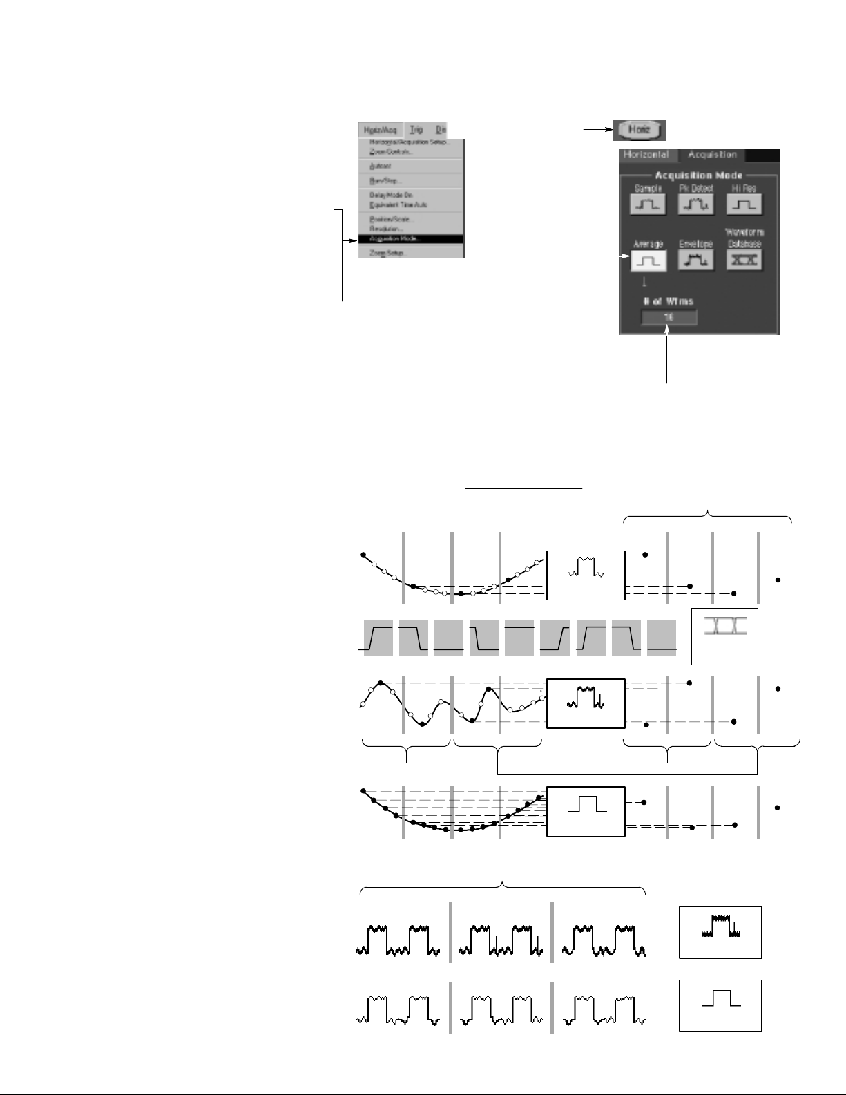
To Choose an Acquisition Mode
Select Acquisition Mode... in the
Horiz/Acq menu.
Or touch the
Horiz button, and then
select an acquisition mode in the
horizontal/acquisition control window.
For Average or Envelope acquisition modes,
touch the
#ofWfmscontrol and then set the
number of waveforms with the multipurpose
knob. You can also double-touch the control
and use the pop-up keypad.
How the Acquisition
Modes Work
Sample mode retains one sampled point from
each acquisition interval.
1
2
acquisition interval =
Interval 1 2 3 4 Interval 1 2 3 4
record duration
number of points in record
Sample
Displayed record points (at
maximum horizontal magnification)
Waveform Data Base mode takes an ensemble
of acquisitions that is best for accurate eye
pattern measurements.
Peak Detect mode uses the highest and
lowest of all the samples contained in two
consecutive acquisition intervals.
Hi Res mode calculates the average of all
the samples for each acquisition interval.
Envelope mode finds highest and lowest record
points over many acquisitions. Envelope uses
Peak Detect for each individual acquisition.
Average mode calculates the average value for
each record point over many acquisitions.
Average uses Sample mode for each individual
acquisition.
Peak Detect
Hi Res
Three acquisitions from one source
Acquisition 1 2 3
Max
WfmDB
Max
MinMin
Envelope
Average
Page 7
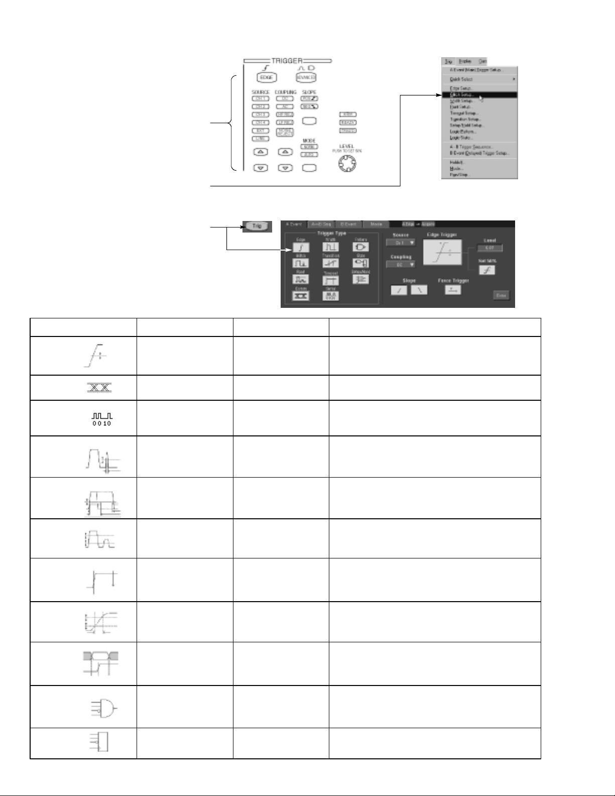
To Select a Trigger
Select the EDGE trigger type and then set the
source, coupling, slope and mode with these
front-panel controls. Push
one of the other trigger types.
You can also select a trigger type in the
ADVANCED to select
Trigger menu.
Or touch the
Trig button and then select a
trigger type in the trigger control window
that is displayed.
Trigger Selections
Trigger type Levels Trigger conditions
Edge
Comm
Serial
Glitch
Width
Single level
Depends on Coding Trigger on telecom signals.None
Single level plus clock
and bit pattern
Single level
Single level
Timers
None
None
One to specify glitch
width
Two to specify minimum
and maximum pulse
widths
Trigger on rising or falling edge, as defined by slope
control. Coupling choices are DC, AC, AC LF Reject, AC
HF Reject, and Noise Reject.
Trigger on serial pattern data.
Trigger on glitches narrower than the specified width or
ignore glitches narrower than the specified width.
Trigger on pulses that have widths between the range of
the two timers or outside the range of the two timers.
Runt
Timeout
Transition
Setup/Hold
Pattern
State
Two levels to define the
logic transition region
Single level
Two levels to define the
logic transition region
Independent levels for
Data and Clock
Independent levels for
each channel
Independent levels for
each channel
Onetospecifyan
optional minimum
runt-pulse duration
One to specify time-out
time
One to specify transition
time
One to specify setup
time and one to specify
hold time
One to specify pattern
duration
None
Trigger on a pulse that enters the transition region from
one side but does not leave the region from the other side.
Trigger when a signal does not make a transition for a
specified length of time.
Trigger when a logic signal spends more time or less time
in the transition region than a specified amount of time.
Trigger on violations of setup or hold time between a Data
signal and a Clock signal. The specified setup and hold
times can be positive or negative values.
Trigger when a Boolean combination of up to four
channels becomes true. Trigger immediately or only after
the combination is true for a specified time duration.
Trigger on transition of one channel when a Boolean
combination of up to three other channels is true.
Page 8

To Use the A (Main) and B (Delayed) Triggers
You can use the A Event (Main) trigger alone or combine it with the B Event (Delayed) trigger to capture more complex signals.
Set the A trigger type and source in
the A Event (Main) tab of the trigger
control window.
Choose a function in the A→ B Sequence tab of
the trigger control window.
Set the trigger delay time or the number
of B events, as appropriate.
Set the B trigger characteristics in the B Event
(Delayed) tab of the trigger control window.
Trigger on B Event
1
2
3
4
Posttrigger
record
A trigger point
Pretrigger
record
Acquired waveform record
The A trigger arms the oscilloscope.
Posttrigger acquisition starts on nth B event.
B Trigger After Delay Time
The A trigger arms the oscilloscope.
Posttrigger acquisition starts on the first B
edge after the trigger delay time.
A trigger
source
B trigger
source
A trigger
source
B trigger
source
Waiting for nth
event (Where n=5)
A trigger point
Trigger
delay time
B trigger point
B trigger point
More Operating Tips:
H B-trigger delay time and horizontal delay time are independent functions. When
you establish a trigger condition using either the A trigger alone or the A and B
triggers together, you can al so use horizontal delay to delay the acquisition by an
additional amount.
H When using the B trigger, the A trigger can be any of the following types: Edge,
Glitch, Width, or Timeout. The B trigger type is always Edge type.
Page 9

To Perform Mask Testing
Select Mask Setup in the mask menu.
Choose a mask type.
Choose a mask standard.
Select Autoset to automatically set up the
controls based on the input signal.
Optionally select Autofit to align each
acquired signal with the mask to minimize the
number of hits.
Use the Source tab to select the source of
your signal.
1
2
3
4
5
Use the Tolerance tab to increase or decrease
the mask margin used in mask testing.
Page 10

To Setup Mask Pass/Fail Testing and View Results
Use the Pass/Fail Setup tab to setup Pass/Fail
testing.
Use the Pass/Fail controls to start, stop, or
continuously run a mask test.
Use the Polarity controls to select testing the
positive, negative, or both the positive and
negative pulses.
Enter the number of waveforms to acquire and
use in your mask test.
Enter the number of waveforms that must fail to
consider the test a failure.
Enter the time that the instrument delays before
starting the mask test.
1
2
3
4
When using masks that enable the Waveform Database mode, the
# of Wfms field changes to # of Sampl es field.
5
6
Use the Pass/Fail Test Notification controls
to select how you want to be notified when
Use the Pass/Fail Results tab to view the
a failure occurs and when the
mask test completes.
results of your mask testing.
Page 11

To Take Automated Measurements
Touch the Meas button, and then select up to
eight measurements using the measurement
Use the tabs to access measurements by
control window.
category.
Or choose a measurement for the selected
waveform directly in the
Measure menu.
Automated Measurement Selections
Amplitude Time More Histogram
Amplitude
High
Low
Max
Min
Pk-- Pk
Rise Time
Fall Time
Positive
Duty Cycle
Positive
Width
Negative
Width
Negative
Duty Cycle
Area
Cycle Area
Phase
Wfm
Count
Hits in
Box
Peak
Hits
Max
Min
Pk-- Pk
ExtRatio
Ext Ratio %
Ext Ratio (dB)
Comm
Eye Height
Eye Width
Crossing %
Eye Top
Eye Base
RMS
Positive
Overshoot
Negative
Overshoot
Cycle
RMS
Mean
Cycle
Mean
Period
Frequency
Delay
Burst
Width
Median
Std Deviation
± 1σ
Mean
± 2σ
± 3σ
Jitter P-P
Jitter RMS
Jitter 6σ
Noise P-P
Noise RMS
S/N Ratio
Cyc Distortion
Q-Factor
Page 12

To Customize an Automated Measurement
Use Gating to confine the measurement
to a certain portion of the waveform.
Turn on measurement statistics to
characterize the stability of the measurement.
Adjust the measurement reference levels to
different relative or different fi xed values.
Select snapshot to see a one-time view of
all valid Normal or Comm measurements.
To Set Up a Histogram
Touch and drag across the segment of the
waveform that you want the histogram to cover.
To set up a horizontal histogram, for example,
make the box wider than it is tall.
Select Histogram Horizontal from the
drop-down list.
View the histogram at the top or edge of
the graticule.
If you need to make any adjustments
to the histogram, use the histogram
setup control window.
1
2
3
4
Take automated measurements on histogram
data. See previous page for information.
5
Page 13

To Take Measurements With Cursors
Push the front-panel CURSORS button.
Select the waveform you want to measure and
a cursor type in the cursor control window.
Or you can activate cursors on the selected
waveform directly in the
Place cursors with the multipurpose knobs
or enter the cursor locations numerically.
Cursor menu.
1
2
3
If you choose split cursors to take
measurements between waveforms,
select the source for each cursor.
Read cursor measurement
results in the display.
4
T1: 356.4 ms
T2: 352.5 ms
∆T: 3.92 ms
1/∆T: 255 Hz
V1: 5.120 V
V2: 4.886 V
∆V: 234 mV
∆V/∆T: 59.7 V/s
5
Other Cursor Measurement Tips:
H You can set the cursors to move together in tandem if you choose the Tracking
cursor mode. The cursors move independently if you choose the Independent
cursor mode.
H If you use the zoom graticule, you can place a cursor directly on a specific
waveform point to take precision measurements.
H You can also move cursors by touching or clicking them and then dragging them
to a new position.
Page 14

To Use Math Waveforms
Select
Math Setup in the Math menu.
1
Choose one of the predefined math equations.
Or touch Editor to define a more advanced
math waveform. Then build the waveform
expression using sources, operators, constants,
measurements, and functions.
To Use Spectral Analysis
Choose Spectral Analysis to define FFT
magnitude and phase waveforms. When an
FFT waveform is selected, you can use the
multipurpose knobs to adjust the FFT waveform
just as you would using a spectrum analyzer.
2
Adjust FFT center
frequency
You can view time-domain and
frequency-domain waveforms
simultaneously. You can also use
gating to select only a portion of the
time-domain waveform for spectral
analysis.
Adjust FFT span
Page 15

To Store Information
To Save and Recall Waveforms
To save or recall waveforms, select
Reference Waveforms and then Save Wfm... or
Recall Wfm... in the File menu.
1
Or touch the
Use the reference setup control window to copy
a live waveform into one of four nonvolatile
reference waveform storage locations. You can
also display these waveforms as reference
Select Save Wfm to File to store the live
waveform as a file on a disk drive. You can
recall a waveform stored on disk int o one
of the internal reference waveform
locations for display.
Refs button.
waveforms.
To Save and Recall Instrument
Setups
To save an instrument setup, select
Instrument Setup in the File menu.
Or touch the
Setups button.
2
3
1
Use the settings control window to save the
current setup into one of ten internal storage
locations. Use the pop-up keyboard to label the
setups for easy identification.
Or select
current setup on a disk drive. You can recall any
setup stored on disk and then save it in an
To restore the oscilloscope to a known initial state,
push the front-panel
Or select
Save Settings to File to store the
internal setup storage location for
quicker access.
DEFAULT SETUP button.
Recall Default Setup in the File menu.
2
3
Page 16

To Print a Hard Copy
To print a hard copy to an attached printer or a
network printer, push the front -panel
PRINT
button.
Or select
you can make changes to the page orientation
Print in the File menu. If necessary,
in the Page Setup dialog box.
The Page Setup dialog box also includes
selectors for the print palette and a feature
called Ink Saver. Ink Saver optimizes the
display colors and shades for printing hard
copies on white paper.
To Copy or Export Your Results
You can use the Windows clipboard to
copy information. Simply select the item
to copy, copy it, and then paste it into
another Windows application.
You can export waveform data into a comma-
separated ACSII file for use in a spreadsheet or
data analysis program. Select
File menu to set the output content and format
for images, waveforms, or measurements.
Export Setup in the
Page 17

To Run Application Software
You can install and run optional application software on your oscilloscope. These software packages provide advanced capability
supporting many applications. Two examples are shown below; additional packages may be available. Contact your Tektronix
representative for more information.
Use
TDSJIT3 Jitter Analysis Software to
characterize timing performance. Analyze
jitter on contiguous clock cycles using
single-shot acquisitions.
Use
TDSUSB2 Software to measure USB
standards.
Follow the instructions provided with the
application software to install it. To run
the software, select the application in the
File / Run Application menu.
Page 18

To Connect to a Network
Like any other Windows computer, you can
connect the oscilloscope to a network to enable
printing, file sharing, internet access, and other
communications functions.
To make a network connection, consult with
your network administrator, and then use the
standard Windows utilities to configure the
oscilloscope for compatibility with your network.
Network
To Use a Dual Monitor
Connect a keyboard, mouse, and monitor to
the oscilloscope and configure Windows for
dual-monitor mode. You can operate t he
oscilloscope while having full use of
Windows and other installed applications on
the external monitor.
Connect the monitor to the upper SVGA port
on the oscilloscope rear panel. Use the
Settings tab in the Windows Display
Properties dialog box to set up a
dual-monitor configuration.
Page 19

To Access the Help System
Touch the HELP button or select Help on
Window
context-sensitive help on the current setup.
Contents and Index in the Help menu to
Select
access any topic in the help system. Select the
topic, and then touch the
in the Help menu to receive
Display buttoninthe
dialog box.
Touch an outlined control shown in the help
window to receive more specific information
Touch a tab in a help window to navigate
between the Overview and specific topics.
Touch the Minimize button in a help window
to move help out of the way so you can
operate the oscilloscope. Touch the
Help
button to see the last help topic again.
about the control.
Restore
Page 20

Front Panel Inputs and Outputs
Floppy disk drive accessible
from Windows
Probe compensator output to compensate
and deskew probes
Auxiliary input to provide an external
trigger input
Auxiliary output to provide trigger
output signal
Analog signal output from the CH 3 input
Channel inputs
Rear Panel Inputs and Outputs
Removable hard disk drive to provide
individual environment for each user or to
secure data; press cover to release the disk
CD-RW drive accessible from Windows;
press cover to open the drive
USB connector for mouse, keyboard, or other
peripherals
Ground terminal
PS-2 connectors for mouse and keyboard
Upper SVGA port to connect a monitor for
dual-monitor operation
Lower VGA port to replicate the oscilloscope
display on an external monitor
Parallel port (Centronics) to
connect printer or other device
GPIB port to connect to controller
RJ-45 connector to connect to network
COM1 serial port
Connectors for speaker and microphone
External reference input and
internal reference output
Page 21

Recommended Probes and Accessories
P7240 4 GHz Active Probe for
general-purpose applications
P7330 Differential Probe for differentialsignal and low-noise applications
TCA-SMA, TCA-BNC 50Ω, and TCA-N
adapters for your probes and cables
P7260 6 GHz 5x/25x Active
Probe
TCA-1MEG Buffer Amplifier to connect
1MΩ accessories
 Loading...