

Page 1

TDSHT3
HDMI Compliance Test Software
Quick Start User Manual
www.tektronix.com
071−1565−01
Page 2

Copyright © Tektronix, Inc. All rights reserved. Licensed software products are owned by Tektronix or its suppliers and are protected by
United States copyright laws and international treaty provisions.
Use, duplication, or disclosure by the Government is subject to restrictions as set forth in subparagraph (c)(1)(ii) of the Rights in Technical
Data and Computer Software clause at DFARS 252.227−7013, or subparagraphs (c)(1) and (2) of the Commercial Computer Software −
Restricted Rights clause at FAR 52.227−19, as applicable.
Tektronix products are covered by U.S. and foreign patents, issued and pending. Information in this publication supercedes that in all
previously published material. Specifications and price change privileges reserved.
Tektronix, Inc., P.O. Box 500, Beaverton, OR 97077
TEKTRONIX and TEK are registered trademarks of Tektronix, Inc.
Page 3

WARRANTY 9(b)
Tektronix warrants that the media on which this software product is furnished and the encoding of the programs on the media will be free
from defects in materials and workmanship for a period of three (3) months from the date of shipment. If any such medium or encoding
proves defective during the warranty period, Tektronix will provide a replacement in exchange for the defective medium. Except as to the
media on which this software product is furnished, this software product is provided as is" without warranty of any kind, either express or
implied. Tektronix does not warrant that the functions contained in this software product will meet Customer’s requirements or that the
operation of the programs will be uninterrupted or error−free.
In order to obtain service under this warranty, Customer must notify Tektronix of the defect before the expiration of the warranty period. If
Tektronix is unable to provide a replacement that is free from defects in materials and workmanship within a reasonable time thereafter,
Customer may terminate the license for this software product and return this software product and any associated materials for credit or
refund.
THIS WARRANTY IS GIVEN BY TEKTRONIX WITH RESPECT TO THE PRODUCT IN LIEU OF ANY OTHER WARRANTIES,
EXPRESS OR IMPLIED. TEKTRONIX AND ITS VENDORS DISCLAIM ANY IMPLIED WARRANTIES OF MERCHANTABILITY OR
FITNESS FOR A PARTICULAR PURPOSE. TEKTRONIX’ RESPONSIBILITY TO REPLACE DEFECTIVE MEDIA OR REFUND
CUSTOMER’S PAYMENT IS THE SOLE AND EXCLUSIVE REMEDY PROVIDED TO THE CUSTOMER FOR BREACH OF THIS
WARRANTY. TEKTRONIX AND ITS VENDORS WILL NOT BE LIABLE FOR ANY INDIRECT, SPECIAL, INCIDENTAL, OR
CONSEQUENTIAL DAMAGES IRRESPECTIVE OF WHETHER TEKTRONIX OR THE VENDOR HAS ADVANCE NOTICE OF THE
POSSIBILITY OF SUCH DAMAGES.
Page 4

Page 5

Table of Contents
General Safety Summary ii. . . . . . . . . . . . . . . . . . . . . . . . . . . . . . . . . . . . . . . . . . . . . . . . . . . . . . . . . . . . . . . . . . . . .
Preface iii. . . . . . . . . . . . . . . . . . . . . . . . . . . . . . . . . . . . . . . . . . . . . . . . . . . . . . . . . . . . . . . . . . . . . . . . . . . . . . . . . .
Key Features iii. . . . . . . . . . . . . . . . . . . . . . . . . . . . . . . . . . . . . . . . . . . . . . . . . . . . . . . . . . . . . . . . . . . . . . . . . .
Documentation iii. . . . . . . . . . . . . . . . . . . . . . . . . . . . . . . . . . . . . . . . . . . . . . . . . . . . . . . . . . . . . . . . . . . . . . . . .
Software Upgrades iv. . . . . . . . . . . . . . . . . . . . . . . . . . . . . . . . . . . . . . . . . . . . . . . . . . . . . . . . . . . . . . . . . . . . . .
Contacting Tektronix iv. . . . . . . . . . . . . . . . . . . . . . . . . . . . . . . . . . . . . . . . . . . . . . . . . . . . . . . . . . . . . . . . . . . . .
Install the Software 1. . . . . . . . . . . . . . . . . . . . . . . . . . . . . . . . . . . . . . . . . . . . . . . . . . . . . . . . . . . . . . . . . . . . . . . . .
Before Installation 1. . . . . . . . . . . . . . . . . . . . . . . . . . . . . . . . . . . . . . . . . . . . . . . . . . . . . . . . . . . . . . . . . . . . . . .
Installation 1. . . . . . . . . . . . . . . . . . . . . . . . . . . . . . . . . . . . . . . . . . . . . . . . . . . . . . . . . . . . . . . . . . . . . . . . . . . .
Connect to the Oscilloscope 1. . . . . . . . . . . . . . . . . . . . . . . . . . . . . . . . . . . . . . . . . . . . . . . . . . . . . . . . . . . . . . .
Start the Software 2. . . . . . . . . . . . . . . . . . . . . . . . . . . . . . . . . . . . . . . . . . . . . . . . . . . . . . . . . . . . . . . . . . . . . . .
Close the Software 4. . . . . . . . . . . . . . . . . . . . . . . . . . . . . . . . . . . . . . . . . . . . . . . . . . . . . . . . . . . . . . . . . . . . . .
Get Acquainted with the Software 5. . . . . . . . . . . . . . . . . . . . . . . . . . . . . . . . . . . . . . . . . . . . . . . . . . . . . . . . . . . . . . .
Use the Interface 5. . . . . . . . . . . . . . . . . . . . . . . . . . . . . . . . . . . . . . . . . . . . . . . . . . . . . . . . . . . . . . . . . . . . . . .
Virtual Keyboard 5. . . . . . . . . . . . . . . . . . . . . . . . . . . . . . . . . . . . . . . . . . . . . . . . . . . . . . . . . . . . . . . . . . . .
Virtual Keypad 6. . . . . . . . . . . . . . . . . . . . . . . . . . . . . . . . . . . . . . . . . . . . . . . . . . . . . . . . . . . . . . . . . . . . . .
General Purpose Knob 7. . . . . . . . . . . . . . . . . . . . . . . . . . . . . . . . . . . . . . . . . . . . . . . . . . . . . . . . . . . . . . . .
Set Preferences 7. . . . . . . . . . . . . . . . . . . . . . . . . . . . . . . . . . . . . . . . . . . . . . . . . . . . . . . . . . . . . . . . . . . . . . . .
Hide and Return the TDSHT3 Software 8. . . . . . . . . . . . . . . . . . . . . . . . . . . . . . . . . . . . . . . . . . . . . . . . . . . . . . .
Use the TDSHT3 Software 9. . . . . . . . . . . . . . . . . . . . . . . . . . . . . . . . . . . . . . . . . . . . . . . . . . . . . . . . . . . . . . . . . . . .
Tests: Process Flow 9. . . . . . . . . . . . . . . . . . . . . . . . . . . . . . . . . . . . . . . . . . . . . . . . . . . . . . . . . . . . . . . . . . . . .
Select a Test 9. . . . . . . . . . . . . . . . . . . . . . . . . . . . . . . . . . . . . . . . . . . . . . . . . . . . . . . . . . . . . . . . . . . . . . . . . .
Configure the Test Parameters 10. . . . . . . . . . . . . . . . . . . . . . . . . . . . . . . . . . . . . . . . . . . . . . . . . . . . . . . . . . . . . .
Connect and Configure the Equipment 10. . . . . . . . . . . . . . . . . . . . . . . . . . . . . . . . . . . . . . . . . . . . . . . . . . . . . . . .
View the Waveform 11. . . . . . . . . . . . . . . . . . . . . . . . . . . . . . . . . . . . . . . . . . . . . . . . . . . . . . . . . . . . . . . . . . . . . .
Run the Test 11. . . . . . . . . . . . . . . . . . . . . . . . . . . . . . . . . . . . . . . . . . . . . . . . . . . . . . . . . . . . . . . . . . . . . . . . . . .
Interpret the Test Result 12. . . . . . . . . . . . . . . . . . . . . . . . . . . . . . . . . . . . . . . . . . . . . . . . . . . . . . . . . . . . . . . . . .
Generate and Print a Report 14. . . . . . . . . . . . . . . . . . . . . . . . . . . . . . . . . . . . . . . . . . . . . . . . . . . . . . . . . . . . . . .
Summary 14. . . . . . . . . . . . . . . . . . . . . . . . . . . . . . . . . . . . . . . . . . . . . . . . . . . . . . . . . . . . . . . . . . . . . . . . .
Detail 15. . . . . . . . . . . . . . . . . . . . . . . . . . . . . . . . . . . . . . . . . . . . . . . . . . . . . . . . . . . . . . . . . . . . . . . . . . . .
Application Examples 18. . . . . . . . . . . . . . . . . . . . . . . . . . . . . . . . . . . . . . . . . . . . . . . . . . . . . . . . . . . . . . . . . . . . . . . .
Source: Select All (Clock−Data Tests) 18. . . . . . . . . . . . . . . . . . . . . . . . . . . . . . . . . . . . . . . . . . . . . . . . . . . . . . . . .
Source: Inter−Pair Skew (Data−Data Tests) 21. . . . . . . . . . . . . . . . . . . . . . . . . . . . . . . . . . . . . . . . . . . . . . . . . . . . .
Sink: Min−Diff Sensitivity Test 24. . . . . . . . . . . . . . . . . . . . . . . . . . . . . . . . . . . . . . . . . . . . . . . . . . . . . . . . . . . . . . .
Sink: Jitter Tolerance Test 26. . . . . . . . . . . . . . . . . . . . . . . . . . . . . . . . . . . . . . . . . . . . . . . . . . . . . . . . . . . . . . . . .
Cable: Eye Diagram Test 29. . . . . . . . . . . . . . . . . . . . . . . . . . . . . . . . . . . . . . . . . . . . . . . . . . . . . . . . . . . . . . . . . .
Enable Remote Control of Test Equipment 32. . . . . . . . . . . . . . . . . . . . . . . . . . . . . . . . . . . . . . . . . . . . . . . . . . . . .
Install NI − 488.2 for Windows 32. . . . . . . . . . . . . . . . . . . . . . . . . . . . . . . . . . . . . . . . . . . . . . . . . . . . . . . . . . .
Connect the Equipment 33. . . . . . . . . . . . . . . . . . . . . . . . . . . . . . . . . . . . . . . . . . . . . . . . . . . . . . . . . . . . . . .
Verify the Equipment Connections 33. . . . . . . . . . . . . . . . . . . . . . . . . . . . . . . . . . . . . . . . . . . . . . . . . . . . . . . .
Set the GPIB Bus Timing 34. . . . . . . . . . . . . . . . . . . . . . . . . . . . . . . . . . . . . . . . . . . . . . . . . . . . . . . . . . . . . .
Configure the GPIB Address 34. . . . . . . . . . . . . . . . . . . . . . . . . . . . . . . . . . . . . . . . . . . . . . . . . . . . . . . . . . . .
Index 36. . . . . . . . . . . . . . . . . . . . . . . . . . . . . . . . . . . . . . . . . . . . . . . . . . . . . . . . . . . . . . . . . . . . . . . . . . . . . . . . . . .
Table of Contents
TDSHT3 HDMI Compliance Test Software Quick Start User Manual
i
Page 6

General Safety Summary
General Safety Summary
Review the following safety precautions to avoid injury and prevent damage to this product or any products connected to it.
To avoid potential hazards, use this product only as specified.
Only qualified personnel should perform service procedures.
While using this product, you may need to access other parts of the system. Read the General Safety Summary in other
system manuals for warnings and cautions related to operating the system.
To Avoid Fire or Personal Injury
Connect and Disconnect Properly. Connect the probe output to the measurement instrument before connecting the
probe to the circuit under test. Disconnect the probe input and the probe ground from the circuit under test before
disconnecting the probe from the measurement instrument.
Observe All Terminal Ratings. To avoid fire or shock hazard, observe all ratings and markings on the product. Consult
the product manual for further ratings information before making connections to the product.
Do not apply a potential to any terminal, including the common terminal, that exceeds the maximum rating of that terminal.
Avoid Exposed Circuitry. Do not touch exposed connections and components when power is present.
Do Not Operate With Suspected Failures. If you suspect there is damage to this product, have it inspected by
qualified service personnel.
Do Not Operate in Wet/Damp Conditions.
Do Note Operate in an Explosive Atmosphere.
Keep Product Surfaces Clean and Dry.
ii
TDSHT3 HDMI Compliance Test Software Quick Start User Manual
Page 7

Preface
+
(Documents folder)
The TDSHT3 HDMI Compliance Test Software is a High Definition Multimedia Interface (HDMI) Compliance Test Solution,
which runs on a Tektronix oscilloscope. This software helps you perform HDMI physical layer validation and compliance
testing.
Key Features
H Conformance to HDMI 1.0 standards and test specifications (CTS version 1.1) ensures reliable results
H Complete validation to standards with wide range of tests for source, sink, and cable devices
H Accurate source tests using precise measurement techniques
H Dependable sink tests with closed−loop measurements that eliminate nonlinearities in test setup
H Automated sink and cable tests with remote control of signal sources
H Automatic mask fit, measurements, and pass or fail notification
H In−depth analysis with statistical analysis and mask margins
H One−button selection of multiple tests
Preface
H One−button csv−format summary and reports
H Complete compliance solution with an elaborate test fixture, signal sources, and TDR
Documentation
This manual describes the installation and basic operation of the TSDHT3 software. For more detailed information, see the
online help. The following information is available for this product:
TDSHT3 Online Help
TDSHT3 Online Help (PDF)
TDSHT3 Quick Start User Manual, English (PDF)
TDSHT3 Quick Start User Manual, Japanese (PDF)
TDSHT3 Quick Reference Card, Source Test (PDF)
TDSHT3 Quick Reference Card, Sink Test (PDF)
Installation Manual: Optional Application Software on
Windows−Based Oscilloscopes
?
Start > Programs > TekApplications > TDSHT3 > Help
C:\TekApplications\TDSHT3\Manuals
www.Tektronix.com
TDSHT3 HDMI Compliance Test Software Quick Start User Manual
iii
Page 8

Preface
Software Upgrades
Periodic software upgrades may become available. Note that the software is only operational if you have a valid option key
for the specific oscilloscope model and serial number.
To check for upgrades:
1. Go to the Tektronix Web site (www.tektronix.com).
2. Select Software and Drivers.
3. Enter the product name (TDSHT3).
Contact Tektronix
Phone 1−800−833−9200
1
Address Tektronix, Inc.
14200 SW Karl Braun Drive
P.O. Box 500
Beaverton, OR 97077
USA
Web site www.tektronix.com
Sales support 1−800−833−9200, select option 1
Service support 1−800−833−9200, select option 2
1
1
Technical support Email: techsupport@tektronix.com
1−800−833−9200, select option 3
1
6:00 a.m. − 5:00 p.m. Pacific time
1
This phone number is toll free in North America. After office hours, please leave a voice mail message.
Outside North America, contact a Tektronix sales office or distributor; see the Tektronix Web site for a list of offices.
iv
TDSHT3 HDMI Compliance Test Software Quick Start User Manual
Page 9

Install the Software
The TDSHT3 software must be installed on a Tektronix oscilloscope. The following models are supported:
H TDS7704B
H TDS7404/B
H CSA7404/B
H TDS7254/B
H TDS6604B
H TDS6804B
H TDS6124C
H TDS6154C
Before Installation
H TekVisa must be installed on the oscilloscope. If you do not have TekVisa, you can download it from the Tektronix Web
site, in the same location as for Software Upgrades (see page iv).
Install the Software
H Please read the Readme.txt file on the product software CD before you install the software.
Installation
1. Close all applications.
2. Insert the product software CD into the CD drive of the oscilloscope.
3. The installation wizard will guide you through the installation. If this is a version upgrade, the existing software will be
automatically removed before the new version is installed.
4. The software files will be installed at C:\Program Files\TekApplications\TDSHT3.
Connect to the Oscilloscope
The various tests require specific equipment setups and specific test adapters. Click More within the connect pane to see
how to connect the device under test and test equipment to your oscilloscope. The following test adapters are required:
H Tektronix HDMI TPA−P−DI (for Differential Source tests)
H Tektronix HDMI TPA−P−SE (for Single−Ended Source tests)
H Tektronix HDMI TPA−P−TDR (for TDR tests)
H Tektronix HDMI TPA−R−DI (for Cable tests and Sink tests)
H Tektronix HDMI TPA−R−SE (for Cable tests and Sink tests)
H Tektronix HDMI TPA−R−TDR (for TDR tests and Sink tests)
TDSHT3 HDMI Compliance Test Software Quick Start User Manual
1
Page 10
Install the Software
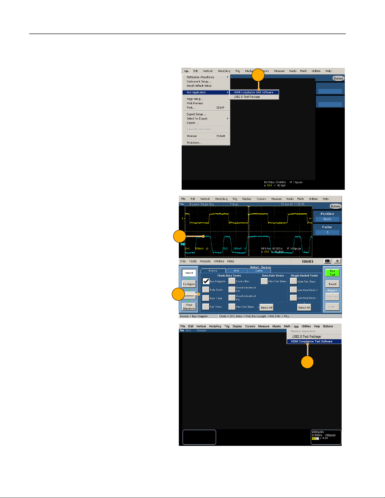
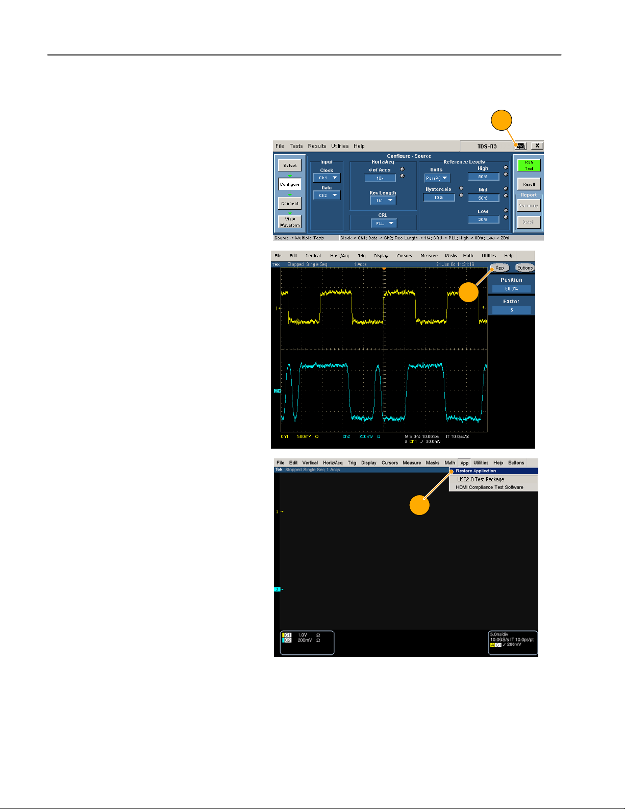
Start the Software
To start supported 7000−series oscillo−
scopes:
1. From the oscilloscope menu, select
File > Run application > HDMI Com−
pliance Test Software.
2. The oscilloscope display resizes to fit
in the upper part of the screen.
3. The software displays in the lower part
of the screen.
4. Proceed to step 5.
1
2
3
To start supported B/C−series oscillo−
scopes:
1. Select App > HDMI Compliance Test
Software.
1
<<Replace with B−series start menu>>
2
TDSHT3 HDMI Compliance Test Software Quick Start User Manual
Page 11

2. The oscilloscope display resizes to fit
in the upper part of the screen.
3. The software displays in the lower part
of the screen.
4. Proceed to step 5.
2
3
NOTE. To ensure accurate results, calibrate the probes and the oscilloscope before you run tests.
Install the Software
5. Click Utilities > Instrument Calibra−
tion to begin calibrating the oscillo−
scope for signal path compensation.
6. Click Calibrate.
5
6
TDSHT3 HDMI Compliance Test Software Quick Start User Manual
3
Page 12
Install the Software
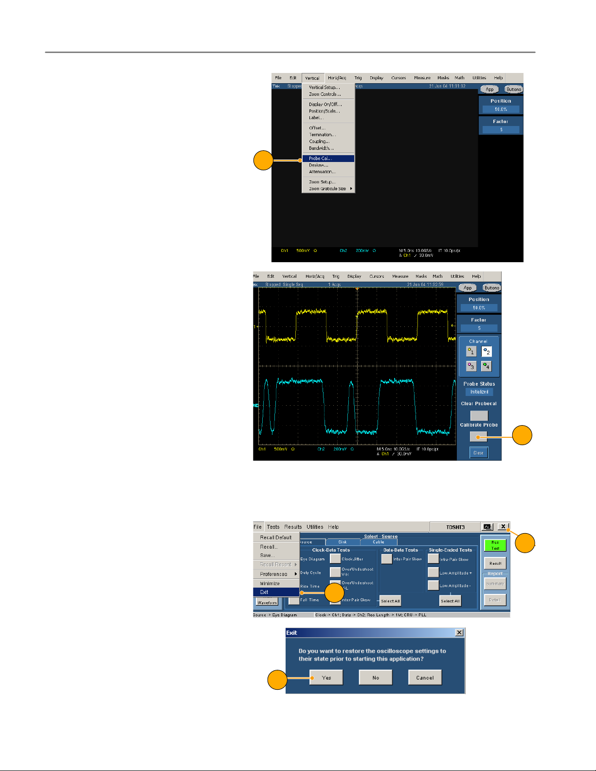
7. Select Vertical > Probe Cal to begin
calibrating the probes.
8. Connect the probe calibration signal to
the probe.
9. Click Calibrate Probe.
8
Close the Software
1. Select File > Exit.
2. You can also click the exit icon.
Using other methods to exit the software
will result in abnormal termination.
3. When you exit the software, you can
restore the oscilloscope to the settings
that were in place before the TDSHT3
software changed them.
9
2
1
3
4
TDSHT3 HDMI Compliance Test Software Quick Start User Manual
Page 13
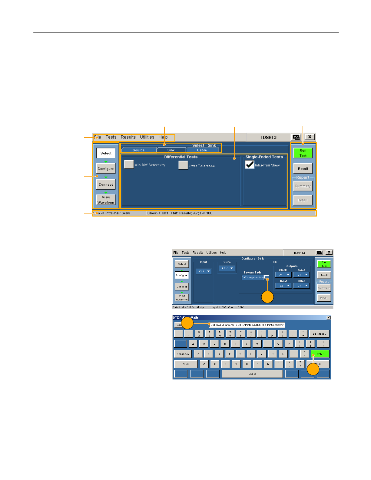
Get Acquainted with the Software
Use the Interface
Use a keyboard, mouse, or touchscreen to make selections in the TDSHT3 software.
Use menus, check boxes, and on−screen buttons to control the software functions. Use Microsoft Windows techniques to
navigate menus and select or clear check boxes.
Get Acquainted with the Software
Menu bar
Selection pane
Status bar
Virtual Keyboard
1. Click a keyboard icon.
Device under test (DUT) type
Client pane
Execution pane
1
2. Clear the existing text and type the
new text.
3. Click Enter to confirm your selection.
NOTE. You must click Enter on the virtual keyboard; otherwise your selections are not valid.
TDSHT3 HDMI Compliance Test Software Quick Start User Manual
2
3
5
Page 14
Get Acquainted with the Software
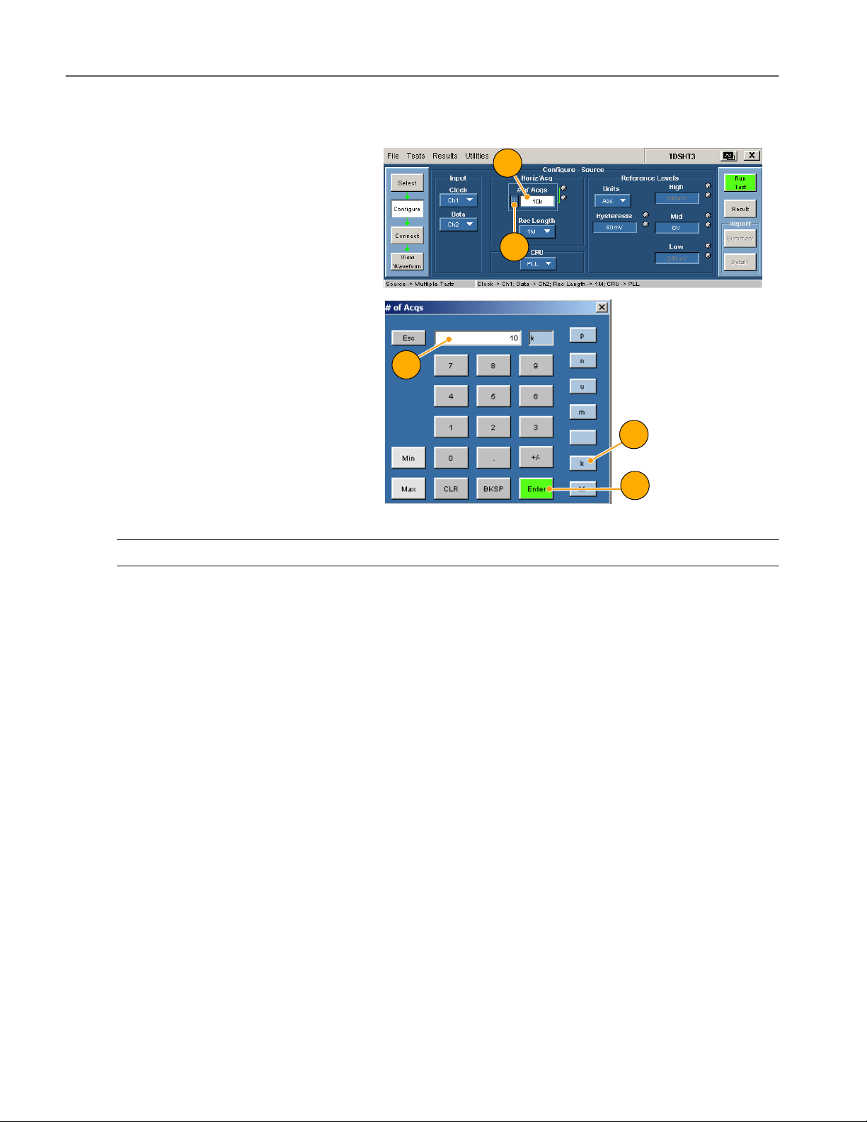
Virtual Keypad
1. Click any number box.
2. Click the keypad icon.
1
2
3. Clear existing value and enter the de−
sired value.
4. Select a unit of measure.
3
5. Click Enter to confirm your selection.
NOTE. You must click Enter on the virtual keypad; otherwise your selections are not valid.
4
5
6
TDSHT3 HDMI Compliance Test Software Quick Start User Manual
Page 15

General Purpose Knob
1. Click any number box to display the
connection to one of the general pur−
pose knobs.
2. Turn the corresponding knob on the
oscilloscope front panel to adjust the
value for the selected parameter.
3. For better resolution, press the FINE
button.
Get Acquainted with the Software
1
2
3
Set Preferences
1. From the TDSHT3 software menu bar,
click File > Preferences, and then se−
lect an option.
2. Click the option again to clear the
selection.
Option Description
Position Eye Mask in Center Selected: Positions the mask at the center of the eye diagram.
Acquisition Alert Message Selected: An alert prompts you to specify oscilloscope settings with
Trigger
Rise/Fall Time or Over/Undershoot
(Available for B/C−series oscilloscopes only)
Cleared: Positions the mask to the left of the eye diagram.
which to run the test.
Cleared: TDSHT3 software selects oscilloscope settings.
These tests can be run with a width trigger or an edge trigger
(default). If the signal has very high intersymbol interference (ISI),
use the width trigger.
TDSHT3 HDMI Compliance Test Software Quick Start User Manual
7
Page 16
Get Acquainted with the Software
Hide and Return the TDSHT3 Software
1. Click the hide icon to minimize the
TDSHT3 software and enlarge the os−
cilloscope display.
To return to the TDSHT3 software:
2. For 7000−series oscilloscopes, select
the APP button.
1
2
3. For 6000B/C and 7000/B−series oscillo−
scopes, select App > Restore Ap−
plication.
3
8
TDSHT3 HDMI Compliance Test Software Quick Start User Manual
Page 17
Use the TDSHT3 Software
Tests: Process Flow
When you make a test, follow the sequence of actions indicated in steps 1 through 6. Details for each of these actions are
given on the following pages.
Use the HDMI Software
1. Select a test.
2. Configure the test parameters.
3. Connect and configure the equipment.
4. View the waveform to verify test signal.
5. Run the test.
6. Interpret the test result.
7. Generate a report.
NOTE. For accurate test results, calibrate the oscilloscope and probes before you begin the tests. See page 3.
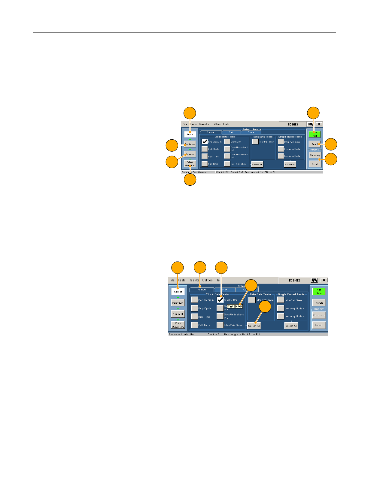
Select a Test
1. Click Select.
2. Click the Source, Sink, or Cable tab.
1
2
3
5
6
7
4
2
41
3. Move the mouse near a test name until
the test ID appears. This ID corre−
sponds to the Test ID in the HDMI
Compliance Test Specifications.
4. Select the test that you want to run.
You can select multiple tests, but they
must all be of the same type.
5. To select all tests of a certain type,
click Select All.
TDSHT3 HDMI Compliance Test Software Quick Start User Manual
3
5
9
Page 18

Use the HDMI Software
Configure the Test Parameters
1. Click Configure.
2. Use the virtual keyboard or the general
purpose knob on the oscilloscope front
panel to change the values if neces−
sary.
You can also use the File menu to
restore factory defaults or save and
recall your own configuration settings.
1
Connect and Configure the Equipment
NOTE. If your test uses remote control, the setup diagram in the online help shows how to connect the test equipment by
using an E−net connection. You can either use this method or you can use the GPIB− B connection described on
pages 32 through 35 of this document. Example tests are shown in the Application Examples section, starting on page 18.
1. Click Connect.
2. Follow the on−screen instructions to
connect and configure the device un−
der test and the test equipment.
3. Click More to view the online help for
the selected test, which contains a set−
up diagram. Connect the test equip−
ment as shown in the diagram.
1
2
3
4
10
4. If the AWG and DTG are used for the
selected test, select Signal Sources
and configure the test equipment. For
more information, see the remote con−
trol procedure on pages 32 through 35
of this document, or refer to the online
help.
TDSHT3 HDMI Compliance Test Software Quick Start User Manual
Page 19

View the Waveform
1. Click View Waveform (not applicable
for all tests).
2. Verify that the waveform in the upper
part of display is similar to the wave−
form that is displayed in the TDSHT3
software.
If the displays are not similar, check
your configuration and connections.
Use the HDMI Software
Run the Test
1. Click Run Test.
2. The test will run, displaying a progress
indicator.
1
2
1
2
TDSHT3 HDMI Compliance Test Software Quick Start User Manual
11
Page 20

Use the HDMI Software
Interpret the Test Result
1. When the test completes, the Result
Summary appears. Check to see if the
device passed the test.
means Pass
means Fail
means Error
If the device did not pass the test, use
steps 2 through 8 to solve the problem,
and then rerun the test.
2. Click Result Details for a spreadsheet
with details about the test result.
1
2
3. Check the Remarks column. If any er−
ror codes are present, see the online
help for error code descriptions.
NOTE. The parameters in the Result Details dialog box may change depending on the test that you run.
3
12
TDSHT3 HDMI Compliance Test Software Quick Start User Manual
Page 21
Use the HDMI Software
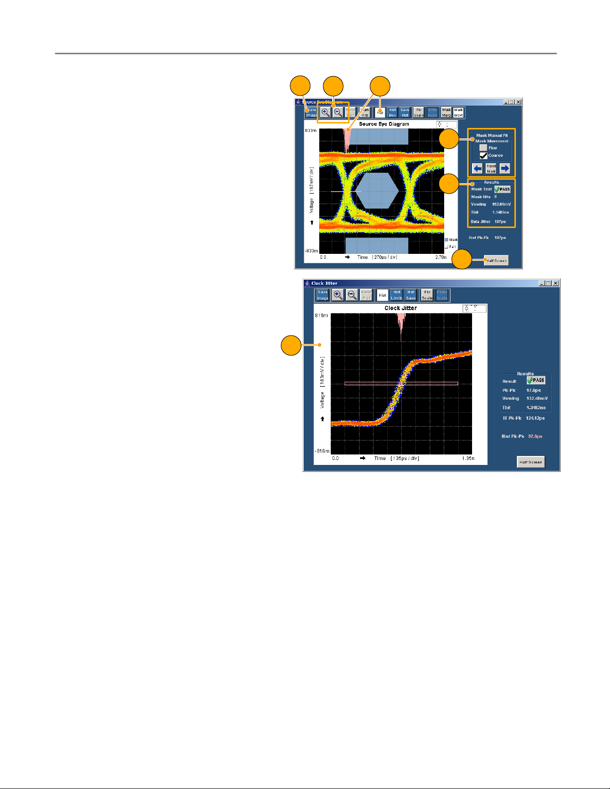
If you ran an eye diagram test, a plot
appears. You can do the following:
4. Save the image to
C:\TekApplications\TDSHT3\Images
(you can also change this path).
5. Zoom in and out.
6. View the histogram.
7. Move the mask to see the margin of
error.
8. View statistics.
9. Change the plot to half screen size
(which returns the Result Summary).
10. A plot also appears if you ran the clock
jitter test. In this plot, you will find the
peak−to−peak jitter of the clock.
10
4
5 6
7
8
9
TDSHT3 HDMI Compliance Test Software Quick Start User Manual
13
Page 22
Use the HDMI Software
Generate and Print a Report
You can generate and print a summary or detailed report as described here.
You can also use the Report Generator to create and print customized reports. You can save files as RTF, or in custom file
formats such as RGT, RPL, and RPT. For more information about the Report Generator, see online help.
Summary
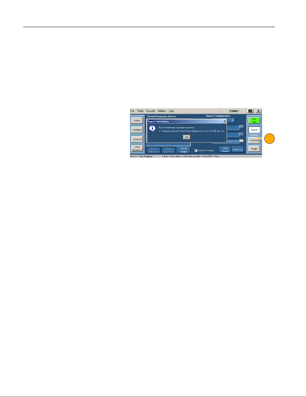
After you have successfully run a test or tests, you can generate a report summary as a .csv file.
1. Click Summary in the execution pane.
2. A message indicates where the report
summary is saved.
3. Open the file and print the report.
1
14
TDSHT3 HDMI Compliance Test Software Quick Start User Manual
Page 23

Use the HDMI Software
Detail
After you run a test, you can generate a report that contains default information or information that you configure.
1. Click Result to begin configuring the
report (or skip to step 14 for defaults).
2. Select the input on which you con−
ducted the test.
3. Enter the resolution at which you con−
ducted the test (such as 40 Hz, 43 Hz,
57 Hz, or 60 Hz).
4. Enter the refresh rate at which you
conducted the test (such as VGA,
SVGA, XGA, or SXGA).
2
3
4
5
1
5. Note the location where the report will
be saved; you can change the location
if desired.
6. Select Enable Preview to view the re−
port on screen when the report is gen−
erated.
7. Click Clear Report to clear all reports.
Reports generated between this and
the next successful test run will have
no values.
8. Click Advanced.
6
7 8
TDSHT3 HDMI Compliance Test Software Quick Start User Manual
15
Page 24
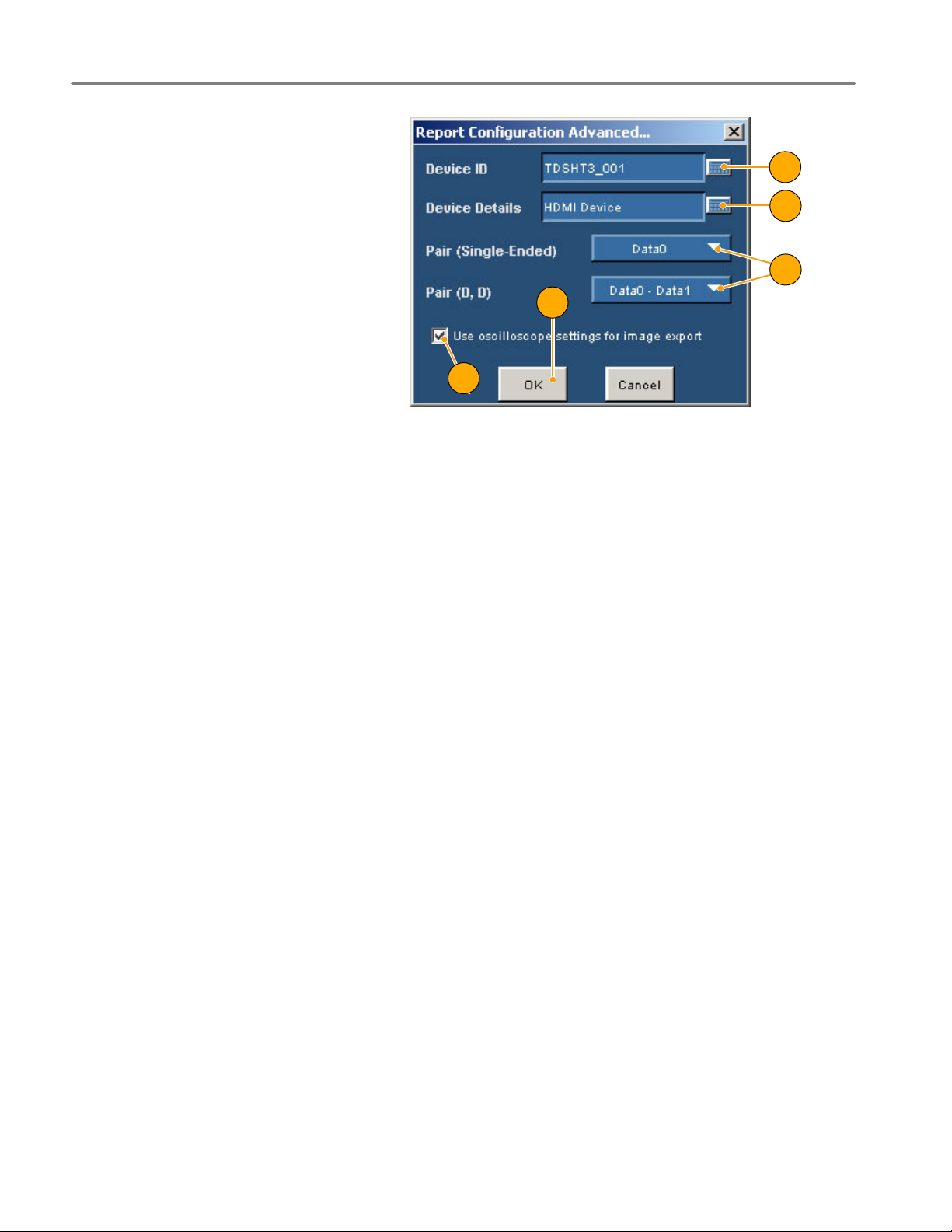
Use the HDMI Software
9. Enter the DUT ID (serial number).
10. Enter the DUT details (product type).
11. Enter the pair(s) that you are using for
single−ended and differential tests.
These entries correspond to the con−
nectors on the HDMI adapter; see the
setup diagrams.
12. When this check box is cleared, the
TDSHT3 software configures the oscil−
loscope to display jpeg images in re−
ports.
If you want to change the default
image export settings, change the
settings in the oscilloscope image
export setup and check this check box.
13. Click OK.
9
10
11
13
12
16
TDSHT3 HDMI Compliance Test Software Quick Start User Manual
Page 25

Use the HDMI Software
14. Click Detail in the report pane to gen−
erate the report.
H If Enable Preview is selected, the
Report Viewer utility displays the
report. Otherwise, a dialog box
displays the location where the
report was saved.
H For an eye diagram or clock jitter
test, a plot is also displayed.
H You can use the Report Viewer
Edit menu to edit the report, if
desired.
H Use the Report Viewer File menu
to print the report or export the
report to an RTF file.
NOTE. The report details are real time and no history is maintained. Save the report details before making another test.
TDSHT3 HDMI Compliance Test Software Quick Start User Manual
17
Page 26

Application Examples
Application Examples
Source: Select All (Clock−Data Tests)
This selection runs a set of tests simultaneously.
Required equipment
2 differential probes; Ground lead Tektronix P7330 or later; Tektronix 196−3469−00
1 DC power supply, set to 3.3 V Kenwood PW18−1.8AQ
1 EDID emulator Silicon Image TE9100
1 input adapter Tektronix TPA−P−DI
Probe Calibration and Deskew fixture Tektronix 067−1478−xx
1. Click Select.
2. Click the Source tab.
3. Click Select All.
Example
1 2
3
18
4. Click Configure. Change these values
if needed. (You can generally use the
default values.)
5. Click Connect.
4
5
TDSHT3 HDMI Compliance Test Software Quick Start User Manual
Page 27

Application Examples
6. Connect and configure the equipment:
H Connect the test equipment as
shown in the setup diagram.
H Configure the source DUT to
output the first supported video
format.
H Configure the EDID Emulator for
the required resolution (refer to the
EDID Emulator user manual).
Digital Oscilloscope
CLOCK
DATA0
DATA1
EDID Emulator
J30
J10
Power Supply
Source DUT
7. Click View Waveform.
Verify that the oscilloscope displays a
similar waveform to the one displayed
by the TDSHT3 software. If the
displays are not similar, check your
configuration and connections.
DATA2
TPA−P−DI
7
TDSHT3 HDMI Compliance Test Software Quick Start User Manual
19
Page 28

Application Examples
To ensure accurate results, deskew the
probes before you run a test.
8. Click Connect.
9. Click Deskew.
10. Set the parameters as follows:
H Select Internal source for this
example.
H Verify that the From channel is set
to Ch1 (reference point).
H Verify that the To channel is set to
Ch2 (channel to be deskewed).
11. Click Run Test to deskew the probes.
12. When deskew completes, click Run
Test to run the test.
13. When the test completes, check the
test results. For more information, see
Interpret the Test Result on page 12.
14. To generate reports based on the tests
that you ran, see Generate and Print a
Report on page 14.
8
13
10
9
11
12
15. After you test the Data0 input pair,
move the probe from Data0 to Data1
and repeat the test. Repeat for Data2.
16. Configure the EDID Emulator for the
next pixel clock rate (VGA, SVGA, and
so on), and test for all three data input
pairs. Only one video format is re−
quired per pixel clock rate.
17. Repeat step 16 for all supported pixel
clock rates.
20
TDSHT3 HDMI Compliance Test Software Quick Start User Manual
Page 29

Source: Inter−Pair Skew (Data−Data Tests)
This test verifies that the skew between the differential pairs in the TMDS portion of the HDMI link is within the limits
stated in the HDMI Specifications.
Required equipment Example
2 differential probes; Ground lead Tektronix P7330 or later; Tektronix 196−3469−00
1 DC power supply, set to 3.3 V Kenwood PW18−1.8AQ
1 EDID emulator Silicon Image TE9100
1 input adapter Tektronix TPA−P−DI
Application Examples
1. Click Select.
2. Click the Source tab.
3. Select Inter−Pair Skew.
4. Click Configure. Change these values
if needed. (You can generally use the
default values.)
5. Click Connect.
1
2
3
4
5
TDSHT3 HDMI Compliance Test Software Quick Start User Manual
21
Page 30

Application Examples
6. Connect and configure the equipment:
H Connect the test equipment as
shown in the setup diagram.
H Configure the source DUT to
output a video format with the
highest supported pixel clock
frequency.
H Configure the EDID Emulator for
the required resolution (refer to the
EDID Emulator user manual).
Digital Oscilloscope
CLOCK
DATA0
DATA1
EDID Emulator
J30
J10
Power Supply
Source DUT
7. Click View Waveform.
Verify that the oscilloscope displays a
similar waveform to the one displayed
by the TDSHT3 software. If the
displays are not similar, check your
configuration and connections.
DATA2
TPA−P−DI
7
22
TDSHT3 HDMI Compliance Test Software Quick Start User Manual
Page 31

Application Examples
Recalculate the Tbit value:
8. Click Configure again.
9. Check that the software is set (default)
to recalculate the Tbit value.
10. If your signal has too much jitter and
noise, increase the value in this box
(default = 100).
11. Click Run Test and then click Contin−
ue to run the test with the new Tbit val−
ue.
12. When the test completes, check the
test results. For more information, see
Interpret the Test Result on page 12.
13. To generate reports based on the tests
that you ran, see Generate and Print a
Report on page 14.
11
8
9
10
12
TDSHT3 HDMI Compliance Test Software Quick Start User Manual
23
Page 32

Application Examples
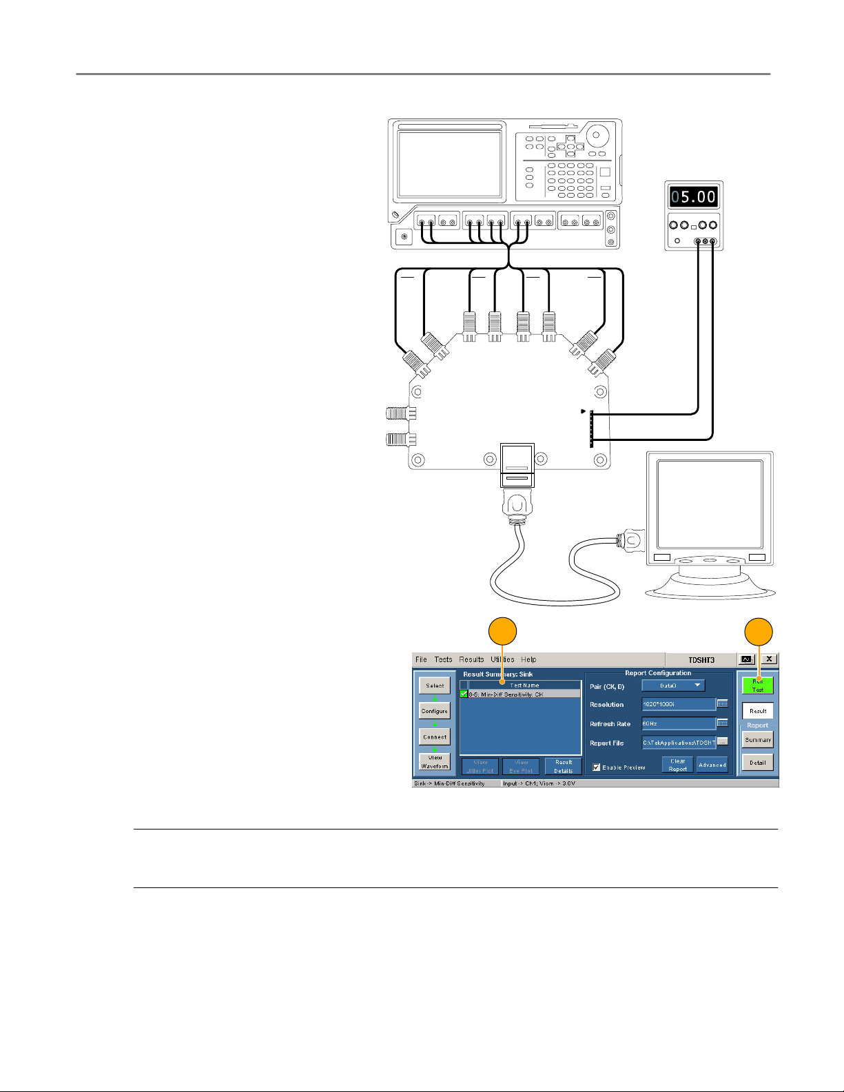
Sink: Min−Diff Sensitivity Test
This test verifies that the sink device properly supports TMDS differential voltages at minimum levels.
Required equipment Example
Digital Timing Generator Tektronix DTG5274 with DTM30 output module
8 SMA cables Tektronix 174−1341−00 1 meter or
1 DC power supply, set to 5.0 V Kenwood PW18−1.8AQ
1 input adapter Tektronix TPA−R−TDR
Tektronix 174−1428−00 1.5 meters
1. Click Select.
2. Click the Sink tab.
3. Select Min−Diff Sensitivity.
4. Click Configure. Change these values
if needed. (You can generally use the
default values.)
5. Click Connect.
21 3
4
24
5
TDSHT3 HDMI Compliance Test Software Quick Start User Manual
Page 33
Application Examples
6. Connect and configure the equipment:
H Connect the test equipment as
shown in the diagram.
H Connect the DTG and oscilloscope
according to the Enable Remote
Control of Test Equipment
procedure on pages 32 through 35.
C1
C1
DATA2_N
DTG5274
DATA1_N
DATA2_P
HDMI TPA−R−TDR
DATA1_P
DATA0_N
B1B1B2B2
DATA0+
A1
CLK_N
CLK_P
Power Supply
A1
Sink DUT
Cable Emulator
7. Click Run Test.
9
8. Follow the series of on−screen mes−
sages.
9. When the test completes, check the
test results. For more information, see
Interpret the Test Result on page 12.
10. To generate reports based on the tests
that you ran, see Generate and Print a
Report on page 14.
NOTE. When you run sink or cable tests, a warning about GPIB Bus Timing appears. If you are sure that the bus timing
parameter is set to 2 msec, click OK to continue. Otherwise, click Cancel and change the bus timing parameter according
to the procedure on page 34.
7
TDSHT3 HDMI Compliance Test Software Quick Start User Manual
25
Page 34
Application Examples
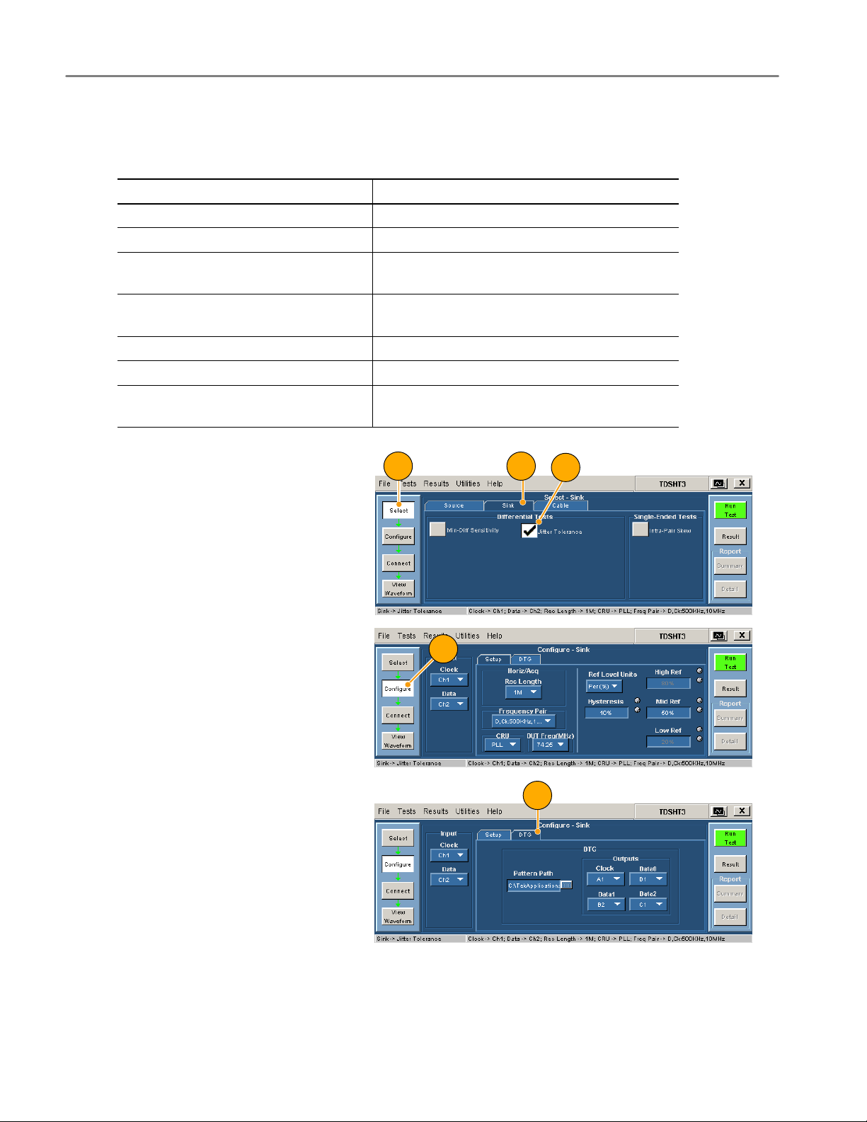
Sink: Jitter Tolerance Test
This test verifies that your device supports the maximum allowed TMDS clock jitter.
Required equipment Example
Digital Timing Generator Tektronix DTG5274 with DTM30 output module
Arbitrary Waveform Generator Tektronix AWG710 or AWG710B
12 SMA cables Tektronix 174−1341−00 1 meter or
1 cable emulator JAE DC1P19ST02700AA for 27 MHz tests
2 bias tees Mini−circuits ZFBT−4R2GW
1 DC power supply, set to 5 V Kenwood PW18−1.8AQ
2 input adapters Tektronix TPA−R−TDR
Tektronix 174−1428−00 1.5 meters
JAE DC1P19ST07425AA for 74.25 MHz tests
Tektronix TPA−R−DI
1. Click Select.
2. Click the Sink tab.
3. Select Jitter Tolerance.
4. Click Configure. Change these values
if needed. (You can generally use the
default values.)
5. Click the DTG tab and configure which
DTG outputs will provide the clock and
data input signals.
1 2
4
3
5
26
TDSHT3 HDMI Compliance Test Software Quick Start User Manual
Page 35
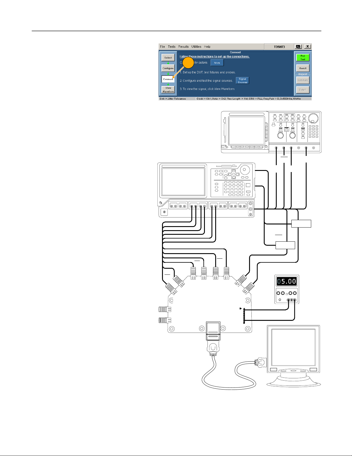
6. Click Connect.
Application Examples
6
7. Connect and configure the equipment:
H Connect the test equipment as
shown in the setup diagram.
H When connecting the test fixture to
the DUT, use a cable emulator
specified for the pixel clock rate
being tested.
H Connect the DTG, AWG, and
oscilloscope according to the
Enable Remote Control of Test
Equipment procedure on pages 32
through 35.
H Configure the DUT to receive the
HDMI input signal.
C1
C1
DATA2_N
DATA2_P
B2
DATA1_N
DTG
B2
DATA1_P
B1
DATA0_N
B1
DATA0+
CLK_N
CLK_P
M1
M2
AWG
CH1
CH1 M1
CH1
Bias Tee
Power Supply
M2
CH1
Bias Tee
TDSHT3 HDMI Compliance Test Software Quick Start User Manual
HDMI TPA−R−TDR
Sink DUT
Cable Emulator
27
Page 36

Application Examples
8. Click Run Test.
9. Follow the series of on−screen mes−
sages.
10. When the test completes, check the
test results. For more information, see
Interpret the Test Result on page 12.
11. To generate reports based on the tests
that you ran, see Generate and Print a
Report on page 14.
NOTE. When you run sink or cable tests, a warning about GPIB Bus Timing appears. If you are sure that the bus timing
parameter is set to 2 msec, click OK to continue. Otherwise, click Cancel and change the bus timing parameter according
to the procedure on page 34.
810
28
TDSHT3 HDMI Compliance Test Software Quick Start User Manual
Page 37
Cable: Eye Diagram Test
This test verifies that the cable assembly outputs a compliant data eye.
Required equipment Example
Digital Timing Generator Tektronix DTG5274 with DTM30 output module
2 differential probes; Ground lead Tektronix P7330 or later; Tektronix 196−3469−00
8 SMA cables Tektronix 174−1341−00 1 meter or
1 DC power supply, set to 3.3 V Kenwood PW18−1.8AQ
2 input adapters Tektronix TPA−P−DI
Application Examples
Tektronix 174−1428−00 1.5 meters
Tektronix TPA−R−DI
Tektronix TPA−P−TDR
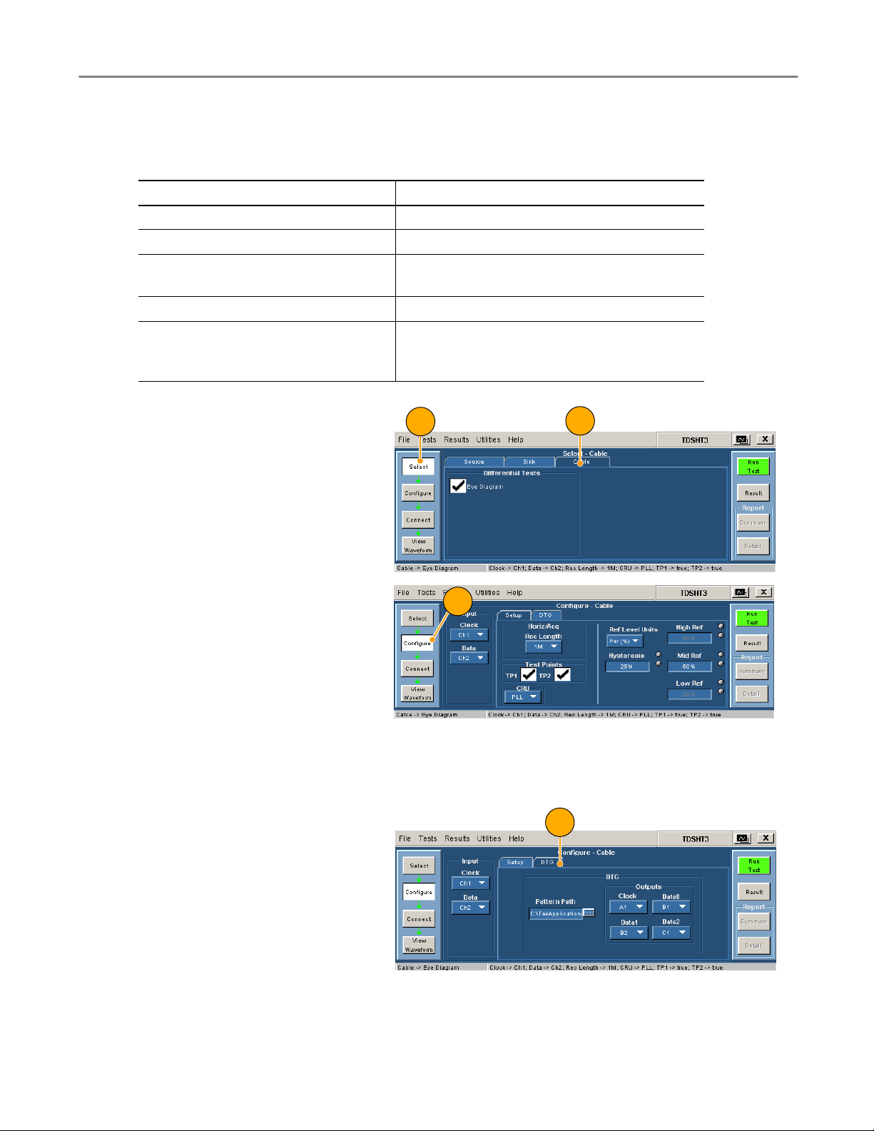
1. Click Select.
2. Click the Cable tab.
3. Click Configure. Change the values if
needed. (You can generally use the de−
fault values.)
H Test Points. For the first cable that
you test, select TP1 and TP2 to
verify both the input test signal
(TP1) and the output of the cable
(TP2). For successive cable tests,
clear TP1.
H CRU. Ensure that PLL (default) is
selected for compliance testing.
4. Click the DTG tab. Configure which
DTG outputs will provide the clock and
data test signals.
1
2
3
4
TDSHT3 HDMI Compliance Test Software Quick Start User Manual
29
Page 38

Application Examples
5. Click Connect.
5
6. Connect and configure the equipment
to verify the test signal input:
H Connect the test equipment as
shown in the TP1 setup diagram.
H Connect the DTG and oscilloscope
according to the Enable Remote
Control of Test Equipment
procedure on pages 32 through 35.
Power Supply
CLOCK
DATA0
DATA1
TPA−P−DI
DATA2
Digital Oscilloscope
A1
J30
J10
CLK_N
CLK_P
DATA0_N
DATA0_P
DATA1_N
DATA1_P
DATA2_N
DATA2_P
DTG
A1
B1
B1
B2
B2
C1
C1
30
NOTE. When you run sink or cable tests, a warning about GPIB Bus Timing appears. If you are sure that the bus timing
parameter is set to 2 msec, click OK to continue. Otherwise, click Cancel and change the bus timing parameter according
to the procedure on page 34.
TDSHT3 HDMI Compliance Test Software Quick Start User Manual
Page 39
Application Examples
7. Click Run Test.
8. Follow the series of on−screen mes−
sages.
9. When the test completes, check the
test results. These results confirm that
the test signal input is compliant. For
more information, see Interpret the
Test Result on page 12.
10. Remove the TPA−P−DI adapter and add
the TPA−R−DI adapter as shown in the
diagram.
11. Add the cable DUT between the
TPA−R−TDR and TPA−R−DI adapters.
12. Click Run Test.
13. When the test completes, check the
test results. Pass indicates HDMI com−
pliance of the cable DUT. For more in−
formation, see Interpret the Test Result
on page 12.
14. Click Configure and set the test point
to TP2.
15. Replace the cable with another cable
DUT and click Run Test.
16. To generate reports based on the tests
that you ran, see Generate and Print a
Report on page 14.
Digital Oscilloscope
TPA−R− DI
J21
DATA2
J23
J22
DATA1
J24
DATA0
CLOCK
7
8
TPA−R− TDR
DATA2_N
DATA2_P
J50
J51
J20
11
J55 J56
DATA1_N
DATA1_P
DATA0_N
DATA0_P
CLOCK_N
CLOCK_P
Power Supply
HOT_PLUG
P_5V
P_GHD
J30
DDC_DATA
DDC_CLOCK
RESERVED
CEC
J10
SND
C1
C1
B2
B2
B1
B1
A1
A1
TDSHT3 HDMI Compliance Test Software Quick Start User Manual
DTG
31
Page 40
Application Examples
Enable Remote Control of Test Equipment
If you are using the specified Tektronix DTG and AWG models, the TDSHT3 software can configure the connected test
equipment automatically as you run tests. If you are using another DTG or AWG, you must configure the test equipment
manually.
Use this procedure to:
H Connect the AWG and DTG for remote control
H Configure the GPIB address for remote control
You will need:
H Tektronix DTG5274, Tektronix AWG710
H Tektronix 7000 series digital oscilloscope
H National Instruments GPIB−USB−B with the included software, NI−488.2 for Windows
Install NI−488.2 for Windows
NOTE. If you already have NI−488.2 installed on your oscilloscope, ensure that you have the version and installation
parameters that are described in step 1. If you do not, then uninstall NI−488.2, and install it according to step 1.
1. Install NI−488.2 for Windows (ver−
sion 2.1 or later).
During installation:
2. Do not install NI−VISA.
3. Install the Measurement & Automation
Explorer.
4. When prompted, enable the GPIB−
USB interface.
5. Restart the oscilloscope.
1
2
3
32
TDSHT3 HDMI Compliance Test Software Quick Start User Manual
Page 41
Connect the Equipment
Application Examples
6. Connect the USB−GPIB controller to
the oscilloscope USB port. The oscillo−
scope operating system detects the
USB−GPIB controller and installs the
driver for it.
7. Using GPIB cables, connect (stack) the
DTG and AWG GPIB connectors to the
GPIB port of the GPIB controller.
If your test does not use the AWG,
connect the GPIB−USB−B between the
oscilloscope and the DTG, omitting the
stacked connector from the AWG.
Verify the Equipment Connections
AWG
DTG
7
GPIB
Oscilloscope
GPIB (Stacked
connectors)
GPIB−USB−B
6
USB
7
8. Open the Measurement & Automation
Explorer that was installed with the
NI−488.2 software.
9. In the Configuration pane, under De−
vices and Interfaces, right−click the
GPIB device.
10. Click Scan for Instruments.
11. Note the GPIB Instrument Number and
the Primary Address.
12. Right−click the instrument and click
Communicate with Instrument.
13. Click Query and check that *IDN? de−
scribes the correct equipment.
10
12
11
9
TDSHT3 HDMI Compliance Test Software Quick Start User Manual
33
Page 42

Application Examples
Set the GPIB Bus Timing
14. Right−click the GPIB device and click
Properties.
15. Click the Advanced tab.
16. In the Bus Timing list, select 2msec.
14
17. Click OK. (Be sure that you complete
the procedure through step 28, where
you will exit the software and restart
the oscilloscope.)
Configure the GPIB Address
18. Start the TDSHT3 software.
19. Click Select.
20. Click the Sink tab.
15
16
17
19
34
21. Select a Differential test, such as Jitter
Tolerance.
20
TDSHT3 HDMI Compliance Test Software Quick Start User Manual
21
Page 43

22. Click Connect.
23. Click Signal Sources.
For the Tektronix DTG5274 generator:
Application Examples
23
22
24. Click the DTG tab.
25. Click GPIB.
26. Click the AWG tab and repeat.
27. Click Test Conn and look for a mes−
sage that the connection is successful.
28. Exit the TDSHT3 software and restart
the oscilloscope.
24
25
26
27
TDSHT3 HDMI Compliance Test Software Quick Start User Manual
35
Page 44

Index
Index
A
Acquisition, 7
Address, Tektronix, iv
Advanced, 15
APP button, 8
Application examples, 18
Cable tests, Eye Diagram, 29
Sink tests
Jitter Tolerance, 26
Min− Diff Sensitivity, 24
Source tests
Inter− Pair Skew, 21
Select All, 18
AWG setup, 32
B
Buttons, 5
C
Cable, Eye Diagram test, 29
Cable emulator, 27
Calibrate probes, 3
Clear report, 15
Client pane, 5
Close the application, 4
Configure, 10
Configure button, 9
Configure test equipment, 32
Configure the GPIB address, 34
Connect, 10
Connect button, 9
Connect test equipment, 32
Connections, 1
Contact Tektronix, iv
CSV file, 14
D
Deskew, 20
Detail, 17
Detailed report, 15
Device under test type, 5
Documentation, iii
DTG setup, 32
DTG5274, 35
DUT Details, 16
DUT ID, 16
DUT type, 5
E
Edge trigger, 7
EDID emulator, 20
Enable Preview, 15, 17
Error codes, 12
Execution pane, 5
Exit button, 4
Exit the software, 4
F
Factory defaults, 10
File
Exit, 4
Preferences, 7
Run application, 2
Fine button, 7
G
General purpose knob, 7, 10
Generate a report, 14
Generator setup, 32
Get acquainted with the application, 5
GPIB, 35
GPIB address, 34
GPIB bus timing, 34
H
Half Screen, 13
HDMI standards conformance, iii
Hide icon, 8
Hide the application, 8
How to
Install your software, 1
Make tests, 9
Operate the Application, 9
I
Installation, 1
Inter− Pair Skew test, 21
Interface, 5
Intersymbol interference, 7
J
Jitter Tolerance test, 26
K
Key features, iii
Keyboard, 5
Knob, 7, 10
M
Make tests, 9
Menu bar, 5
Menus, 5
Min−Diff Sensitivity test, 24
Mouse, 5
Multiple tests, 9
N
NI− 488.2 for Windows, 32
O
Oscilloscope general purpose knob, 10
P
Pair, 15
Pixel clock rates, 20
Position eye mask in center, 7
Preferences, 7
Print a report, 14
Product description, iii
Product support, iv
R
Recalculate Tbit value, 23
Refresh Rate, 15
Related documentation, iii
Remote control, 32
Report File, 15
Report file formats, 14
Report summary, 14
Resolution, 15
Restore application, 8
Result Details, 12
Results, 12
Results button, 9
Return to the application, 8
RGT format, 14
RPL format, 14
36
TDSHT3 HDMI Compliance Test Software Quick Start User Manual
Page 45

Index
RPT format, 14
RTF format, 14
Run Test, 11
Run Test button, 9
S
Select button, 9
Select All, 9, 18
Select multiple tests, 9
Selection pane, 5
Service support, contact information, iv
Set preferences, 7
Signal Sources, 35
Sink, Differential
Jitter Tolerance test, 26
Min− Diff Sensitivity test, 24
Software upgrades, iv
Source, Data−Data, Inter −Pair Skew
test, 21
Source tab, 9
Source tests, Select All, 18
Start the application, 2
Status bar, 5
SVGA, 20
T
Tbit value, 23
Technical support, iv
Tektronix, contact, iv
TekVisa, 1
Test Conn, 35
Test equipment, 32, 33
Connect, 10
Setups, 1
Test ID, 9
Test ID 5− 3, 29
Test ID 8− 5, 24
Test ID 8− 7, 26
Test parameters, Configure, 10
Test results, 12
Tests, Process flow, 9
Touch screen, 5
TPA− P −DI, 1
TPA− P −SE, 1
TPA− R −DI, 1
TPA− R −SE, 1
TPA− R −TDR, 1
Trigger, 7
U
Use oscilloscope settings for image
export, 16
Use the interface, 5
V
VGA, 20
View test results, 12
View Waveform, 11
View Waveform button, 9
Virtual keyboard, 5, 10
Virtual keypad, 6
W
Web site address, Tektronix, iv
Width trigger, 7
TDSHT3 HDMI Compliance Test Software Quick Start User Manual
37
Page 46

 Loading...