


Service Manual
TDS6000B & TDS6000C Series
Digital Storage Oscilloscope
071-1798-00
This document applies to firmware version 4.00
and above.
Warning
The servicing instructions are for use by qualified
personnel only. To avoid personal injury, do not
perform any servicing unless you are qualified to
do so. Refer to all safety summaries prior to
performing service.
www.tektronix.com

Copyright © Tektronix, Inc. All rights reserved. Licensed software products are owned by Tektronix or its subsidiaries or
suppliers, and are protected by national copyright laws and international treaty provisions.
Tektronix products are covered by U.S. and foreign patents, issued and pending. Information in this publication supercedes
that in all previously published material. Specifica tions and price change privileges reserved.
TEKTRONIX and TEK are registered trademarks of Tektronix, Inc.
Contacting Tektronix
Tektronix, Inc.
14200 SW Karl Braun Drive
P.O. Box 500
Beaverton, OR 97077
USA
For product information, sales, service, and techni cal support:
H In North America, call 1-800-833-9200.
H Worldwide, visit www.tektronix.com to find contacts in your area.

Warranty 2
Tektronix warrants that this product will be free from defects in materials and workmanship for a period of one (1)
year from the date of shipment. If any such product proves defective during this warranty period, Tektronix, at its
option, either will repair the defective product without charge for parts and labor, or will provide a replacement in
exchange for the defective product. Parts, modules and replacement products used by Tektronix for warranty work
may be new or reconditioned to like new performance. All replaced parts, modules and products become the
property of Tektronix.
In order to obtain service under this warranty, Customer must notify Tektronix of t he defect before the expiration
of the warranty period and make suitable arrangements for the performance of service. Customer shall be
responsible for packaging and shipping the defective product to the service center designated by Tektronix, with
shipping charges prepaid. Tektronix shall pay for the return of the product to Customer if the shipment is to a
location within the country in which the Tektronix service center is locat ed. Customer shall be responsible for
paying all shipping charges, duties, taxes, and any other charges for produc ts returned to any other locations.
This warranty shall not apply to any defect, failure or damage caused by improper use or improper or inadequate
maintenance and care. Tektronix shall not be obligated to furnish service under this warranty a) to repair damage
resulting from attempts by personnel other than Tektronix representatives to install, repair or service the product;
b) to repair damage resulting from improper use or connection to incompatible equipment; c) to repair any
damage or malfunction caused by the use of non-Tektronix supplies; or d) to service a product that has been
modified or integrated with other products when the effect of such modification or integration increases the time
or difficulty of servicing the product.
THIS WARRANTY IS GIVEN BY TEKTRONIX WITH RESPECT TO THE PRODUCT IN LIEU OF ANY
OTHER WARRANTIES, EXPRESS OR IMPLIED. TEKTRONIX AND ITS VENDORS DISCLAIM ANY
IMPLIED WARRANTIES OF MERCHANTABILITY OR FITNESS FOR A P ARTICULAR PURPOSE.
TEKTRONIX’ RESPONSIBILITY TO REPAIR OR REPLACE DEFECTIVE PRODUCTS IS THE SOLE AND
EXCLUSIVE REMEDY PROVIDED TO THE CUSTOMER FOR BREACH OF THIS WARRANTY.
TEKTRONIX AND ITS VENDORS WILL NOT BE LIABLE FOR ANY INDIRECT, SPECIAL, INCIDENTAL,
OR CONSEQUENTIAL DAMAGES IRRESPECTIVE OF WHETHER TEKTRONIX OR THE VENDOR HAS
ADVANCE NOTICE OF THE POSSIBILITY OF SUCH DAMAGES.


Table of Contents
Operating Information
Theory of Operation
Figures iii...................................................
Tables iv...................................................
General Safety Summary v...................................
Service Safety Summary vii....................................
Environmental Considerations ix...............................
Preface xi...................................................
Manual Conventions xi..............................................
Installation and Operating Information 1--1...............................
Module Overviews 2--1...............................................
General 2--1....................................................
Input Signal Path 2--1.............................................
Display Panel 2--1................................................
Front Panel 2--2..................................................
Rear Panel 2--2..................................................
Low Voltage Power Supply 2--2.....................................
Fans 2--3.......................................................
Block diagram 2--3..................................................
Adjustment Procedure
Maintenance
Preventing ESD 4--1.................................................
Inspection and Cleaning 4--2...........................................
General Care 4--2................................................
Flat Panel Display Cleaning 4--2....................................
Interior Cleaning 4--3.............................................
Exterior Cleaning 4--3............................................
Inspection 4--3..................................................
Removal and Installation Procedures 4--7.........................
Preparation 4--7.....................................................
Trim, Cabinet, and Module Removal 4--9.................................
TDS6000B & TDS6000C Series Service Manual
i

Table of Contents
Removal Procedures 4--13..............................................
Acquisition Module 4--13...........................................
MicroATX Module 4--13...........................................
Bridge Module 4--14...............................................
PowerPC (PPC) Module 4--14.......................................
CD--ROM Drive 4--15.............................................
Display 4--15.....................................................
Side Fans 4--15...................................................
Internal Fans 4--15................................................
Front Panel 4--16..................................................
USB Module 4--16................................................
Hard Disk Drive 4--16.............................................
Troubleshooting 4--17...........................................
Service Level 4--17...................................................
Check for Common Problems 4--17......................................
Equipment Required 4--19..............................................
Fault Isolation Procedure 4--19..........................................
Checking the Power Supply Voltages 4--21.............................
If the Oscilloscope Will Not Boot 4--24................................
Booting Into Windows 4--24.........................................
If the Oscilloscope Application Does Not Work 4--24....................
PPC and MicroATX PC Diagnostics 4--25.................................
Power--on diagnostics 4--25.........................................
Checkit Utilities 4--27..............................................
Diagnostics 4--28.................................................
Software Updates 4--28................................................
After Repair 4--29....................................................
BIOS Error Messages 4--29.............................................
BIOS Beep Codes 4--31................................................
DIP Switch Controls 4 --31..............................................
Diagnostic LED 4--32.................................................
Troubleshooting Using Reset Circuits 4--34................................
Update/Restore the MicroATX Board CMOS 4--36..........................
Installing an Authorization Key 4--37.....................................
Repackaging Instructions 4--39...................................
Packaging 4--39......................................................
Shipping to the Service Center 4--39......................................
Mechanical Parts List
ii
Parts Ordering Information 5--1.........................................
Module Servicing 5--1............................................
Using the Replaceable Parts List 5--2....................................
Abbreviations 5--2...............................................
Mfr. Code to Manufacturer Cross Index 5--2...........................
TDS6000B & TDS6000C Series Service Manual

List of Figures
Table of Contents
Figure 2--1: TDS6000B and TDS6000C series block diagram 2--3......
Figure 4--1: Locator for trim and cabinet removal 4--11...............
Figure 4--2: Locator for internal modules 4--12......................
Figure 4--3: Primary troubleshooting tree 4--20......................
Figure 4--4: Low voltage power supply LED locations 4--21...........
Figure 4--5: Location of power--on and overcurrent LEDs 4--22........
Figure 4--6: Connectors J1, J2, and J3 4--23........................
Figure 4--7: The three PCI busses 4--34............................
Figure 4--8: PCI and MicroATX video connectors 4--35...............
Figure 4--9: Switch, jumper, and reset button locations 4--36...........
Figure 5--1: External parts 5--7..................................
Figure 5--2: Front panel and drives 5--10...........................
Figure 5--3: Front panel and drives (cont.) 5--12.....................
Figure 5--4: Power supply 5 --14...................................
Figure 5--5: ATX module detail 5--16..............................
Figure 5--6: Accessories 5--17.....................................
TDS6000B & TDS6000C Series Service Manual
iii

Table of Contents
List of Tables
T able 4--1: External inspection check list 4--3......................
Table 4--2: Tools required for module removal 4--8.................
Table 4--3: Column legend for Table 4--5 4--9......................
Table 4--4: Accessing modules 4--9...............................
Table 4--5: Failure symptoms and possible causes 4--17...............
Table 4--6: LVPS LED descriptions 4--21...........................
Table 4--7: Power supply voltages 4--23............................
Table 4--8: Power--on diagnostic tests 4--25.........................
Table 4--9: Action required for module replacement 4--29.............
Table 4--10: BIOS error messages 4--30............................
T able 4--11: Beep codes 4--31.....................................
Table 4--12: DIP switch functions 4--32.............................
Table 4--13: Diagnostic LED 4--33.................................
iv
TDS6000B & TDS6000C Series Service Manual

General Safety Summary
Review the following safety precautions to avoid injury and prevent damage to
this product or any products connected to it.
To avoid potential hazards, use this product only as specified.
Only qualified personnel should perform service procedures.
While using this product, you may need to access other parts of a larger system.
Read the safety sections of the other component manuals for warnings and
cautions related to operating the system.
ToAvoidFireor
Personal Injury
Use Proper Power Cord. Use only the power cord specified for this product and
certified for the country of use.
Connect and Disconnect Properly. Do not connect or disconnect probes or test
leads while they are connected to a voltage source.
Ground the Product. This product is grounded through the grounding conductor
of the power cord. To avoid electric shock, the grounding conductor must be
connected to earth ground. Before making connections to the input or output
terminals of the product, ensure that the product is properly grounded.
Observe All Terminal Ratings. To avoid fire or shock hazard, observe all ratings
and markings on the product. Consult the product manual for further ratings
information before making connections to the product.
The inputs are not rated for connection to mains or Category II, III, or IV
circuits.
Connect the probe reference lead to earth ground only.
Do not apply a potential to any terminal, including the common terminal, that
exceeds the maximum rating of that terminal.
Power Disconnect. The power cord disconnects the product from the power
source. Do not block the power cord; it must remain accessible to the user at all
times.
Do Not Operate Without Covers. Do not operate this product with covers or panels
removed.
Do Not Operate With Suspected Failures. If you suspect there is damage to this
product, have it inspected by qualified service personnel.
Avoid Exposed Circuitry. Do not touch exposed connections and components
when power is present.
Use Proper Fuse. Use only the fuse type and rating specified for this product.
TDS6000B & TDS6000C Series Service Manual
v

General Safety Summary
Wear Eye Protection. Wear eye protection if exposure to high-intensity rays or
laser radiation exists.
Do Not Operate in Wet/Damp Conditions.
Do Not Operate in an Explosive Atmosphere.
Keep Product Surfaces Clean and Dry.
Provide Proper Ventilation. Refer to the manual’s installation instructions for
details on installing the product so it has proper ventilation.
Terms in this Manual
Symbols and Terms
on the Product
These terms may appear in this manual:
WARNING. Warning statements identify conditions or practices that could result
in injury or loss of life.
CAUTION. Caution statements identify conditions or practices that could result in
damage to this product or other property.
These terms may appear on the product:
H DANGER indicates an injury hazard immediately accessible as you read the
marking.
H WARNING indicates an injury hazard not immediately accessible as you
read the marking.
H CAUTION indicates a hazard to property including the product.
The following symbols may appear on the product:
CAUTION
Refer to Manual
WARNING
High Voltage
vi
Protective Ground
(Earth) Terminal
TDS6000B & TDS6000C Series Service Manual
Earth Terminal
Standby

Service Safety Summary
Only qualified personnel should perform service procedures. Read this Service
Safety Summary and the General Safety Summary before performing any service
procedures.
Do Not Service Alone. Do not perform internal service or adjustments of this
product unless another person capable of rendering first aid and resuscitation is
present.
Disconnect Power. To avoid electric shock, switch off the instrument power, then
disconnect the power cord from the mains power.
Use Care When Servicing With Power On. Dangerous voltages or currents may
exist in this product. Disconnect power, remove battery (if applicable), and
disconnect test leads before removing protective panels, soldering, or replacing
components.
To avoid electric shock, do not touch exposed connections.
TDS6000B & TDS6000C Series Service Manual
vii

Service Safety Summary
viii
TDS6000B & TDS6000C Series Service Manual
Environmental Considerations
This section provides information about the environmental impact of the
product.
Product End-of-Life
Handling
Observe the following guidelines when recycling an instrument or component:
Equipment Recycling. Production of this equipment required the extraction and
use of natural resources. The equipment may contain substances that could be
harmful to the environment or human health if improperly handled at the
product’s end of life. In order to avoid release of such substances into the
environment and to reduce the use of natural resources, we encourage you to
recycle this product in an appropriate system that will ensure that most of the
materials are reused or recycled appropriately.
The symbol shown to the left indicates that this product
complies with the European Union’s requirements
according to Directive 2002/96/EC on waste electrical and
electronic equipment (WEEE). For information about
recycling options, check the Support/Service section of the
Tektronix Web site (www.tektronix.com).
Mercury Notification. This product uses an LCD backlight lamp that contains
mercury. Disposal may be regulated due to environmental considerations. Please
contact your local authorities or, within the United States, the Electronics
Industries Alliance (www.eiae.org) for disposal or recycling information.
Restriction of Hazardous
Substances
TDS6000B & TDS6000C Series Service Manual
This product has been classified as Monitoring and Control equipment, and is
outside the scope of the 2002/95/EC RoHS Directive. This product is known to
contain lead, cadmium, mercury, and hexavalent chromium.
ix

Environmental Considerations
x
TDS6000B & TDS6000C Series Service Manual

Preface
Manual Conventions
This is the service manual for the TDS6000B & TDS6000C Digital Storage
Oscilloscope products. Read this preface to learn how this manual is structured,
what conventions it uses, and where you can find other information related to
servicing this product. Read the safety summaries preceding this preface for
safety and other important background information needed before using this
manual to service this product.
This manual uses certain conventions that you should become familiar with
before attempting service.
Replaceable Parts
Safety
This manual refers to any field-replaceable assembly or mechanical part
specifically by its name or generically as a replaceable part or module. In
general, a replaceable part is any circuit board or assembly, such as the hard disk
drive, or a mechanical part, such as the I/O port connectors, that is listed in the
replaceable parts list.
Symbols and terms related to safety appear in the Service Safety Summary found
at the beginning of this manual.
TDS6000B & TDS6000C Series Service Manual
xi

Preface
xii
TDS6000B & TDS6000C Series Service Manual

Operating Information


Operating Information
For information on installing and operating your TDS6000B or TDS6000C
Series Digital Storage Oscilloscope, refer to the TDS6000B & TDS6000C Series
Digital Storage Oscilloscopes Quick Start User Manual. This manual is
available on the Web at www.tektronix.com.
TDS6000B & TDS6000C Series Service Manual
1- 1

Operating Information
1- 2
TDS6000B & TDS6000C Series Service Manual

Theory of Operation


Theory of Operation
This section describes the electrical operation of the oscilloscope. Figure 2--1 on
page 2--3 shows the module interconnections.
Module Overviews
Module overviews describe the basic operation of each functional circuit block
asshowninFigure2--1onpage2--3.
General
Input Signal Path
A dual-processor system controls the oscilloscope. The oscilloscope features an
XGA resolution flat-panel display, a transparent touch screen, and a front-panel
with direct access to commonly used oscilloscope functions. You can also use
the oscilloscope with a mouse pointing device or keyboard.
A signal enters the oscilloscope through a direct coaxial connection to the input
connector, or a probe connected to the front panel.
Acquisition Board. The acquisition board conditions the input signals, samples
them, converts them to digital signals, and controls the acquisition process under
direction of the processor system. The acquisition system includes the multisource trigger, acquisition timebase, and acquisition mode generation and control
circuitry. The acquisition board is located in the bottom compartment of the
oscilloscope. Four vertical channels are accommodated. All channels feature a
TekConnectr interface for additional front-end signal conditioning functions.
Processor System. The processor system contains two processor boards with
microprocessors that control the entire oscilloscope.
Display Panel
TDS6000B & TDS6000C Series Service Manual
Waveforms and menus are displayed on a 10.4 inch, color, active-matrix LCD
display with touch panel.
Display System. Text and waveforms are processed by different parts of the
display circuitry. The display system (display adapter board and inverter board)
sends the text and waveform information to the display panel.
Touch Panel. The display board sends information from the touch panel to the
processor. Any changes in settings are reported to the processor system.
2- 1

Theory of Operation
Front Panel
The MicroATX board reads the front-panel switches and encoders. Any changes
in their settings are reported to the processor system. The MicroATX board also
turns the LEDs on and off.
Menu Switches. Front-panel menu switches are also read by the MicroATX board.
The touch screen processor sends any changes in menu selections to the
MicroATX processor system. The ON/STBY switch passes through the display
adapter board to the MicroATX board. The MicroATX board creates the signal
sent to the power supply to toggle power.
PowerPC Board. The PowerPC (PPC) board provides fast access to the Acquisition board and the display system. The MicroATX board reads the front-panel
switches and encoders and implements any changes requested by their settings.
The PPC board provides a GPIB interface through a rear panel connector.
MicroATX Board. The MicroATX board provides standard Windows functionality
and I/O port interfaces to the rear panel.
Micro ATX Bridge Board. Both processor systems, CDROM-RW drive, and hard
disk drive are connected together by, and communicate through, the bridge
board.
Rear Panel
Low Voltage Power Supply
The hard disk drive and CDROM-drive provide access to stored waveform data
and software to customize your oscilloscope with your measurement needs. The
GPIB allows for external control of the oscilloscope.
You can make hardcopies via the USB and parallel ports.
The MicroATX board has four USB ports and one serial port on the rear panel.
The MicroATX board also provides a front panel USB port. The MicroATX has
one serial port, which is routed to the rear panel. A microphone input and
earphone output exist on the MicroATX rear panel. Ethernet connector is RJ-45.
Keyboard and mouse are both PS/2.
The low voltage power supply is a switching power converter with active power
factor control. It supplies power to all of the circuitry in the oscilloscope.
The ON/STBY switch, located on the front panel, also controls all of the power
to the oscilloscope except for part of the circuitry in the standby power supply.
The power supply sends a power fail (~PF) warning to the processor and
acquisition systems if the power is going down.
Power is distributed throughout the oscilloscope through the front and rear power
distribution bus boards.
2- 2
TDS6000B & TDS6000C Series Service Manual
Theory of Operation
Block Diagram
Touch
panel
ON/STANDBY
Display
panel
Fans
Display
adapter
board
Two fan assemblies (six on the Side Fan Assembly and four on the Internal Fan
Assembly) provide forced air cooling for the oscilloscope. The fans are
controlled by the PPC.
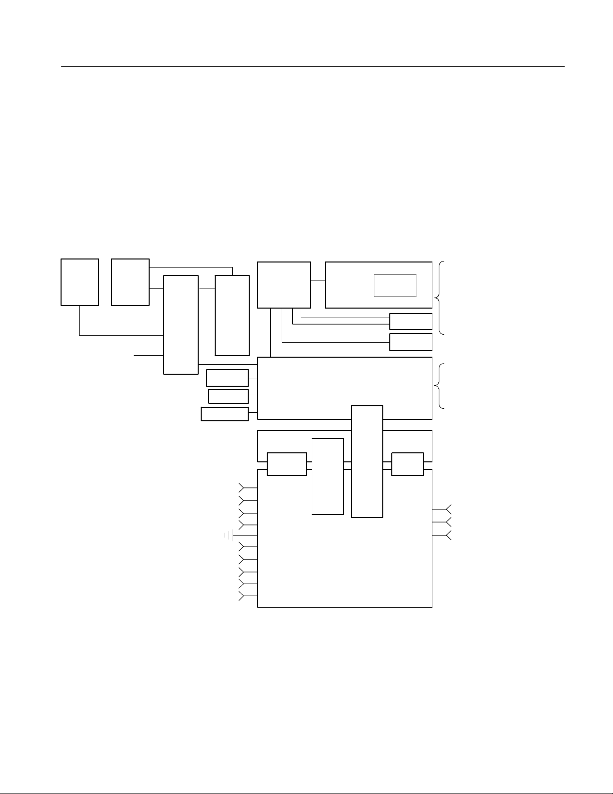
This section contains the block diagram of the TDS6000B and TDS6000C
Digital Storage Oscilloscopes and modules, showing the major circuit blocks or
modules. The block diagram is shown in Figure 2--1, below.
SVGA
USB
Sound
Serial
Parallel
Ethernet
Mouse
Keyboard
GPIB
SCOPE
XGA OUT
Inverter
board
Front panel
Side fans
Internal fans
Bridge
MicroATX board
board
Power PC Processor board
Processor
CD ROM
Hard drive
LVPS board
AUX bus PA bus
Ch1
Ch2
Ch3
Ch4
AUX TRIG OUT
DC PROBE CAL
RECOVERED DATA
RECOVERED CLOCK
FAST EDGE
Figure 2- 1: TDS6000B and TDS6000C series block diagram
Power
bus
(front)
Power
bus
(rear)
REF
AUX IN
AUX IN
Acquisition
board
TDS6000B & TDS6000C Series Service Manual
2- 3

Theory of Operation
2- 4
TDS6000B & TDS6000C Series Service Manual

Adjustment Procedures


Adjustment Procedures
There are no user adjustment procedures for the TDS6000B and TDS6000C
Digital Storage Oscilloscopes. Adjustment of these instruments must be
performed by a Tektronix Service Center.
TDS6000B & TDS6000C Series Service Manual
3- 1

Adjustment Procedures
3- 2
TDS6000B & TDS6000C Series Service Manual

Maintenance


Maintenance
This section contains the information needed to do periodic and corrective
maintenance on the oscilloscope. The following subsections are included:
H Preventing ESD — General information on preventing damage by electros-
tatic discharge.
H Inspection and Cleaning — Information and procedures for inspecting the
oscilloscope and cleaning its external and internal modules.
H Removal and Installation Procedures — Procedures for the removal of
defective modules and replacement of new or repaired modules. Also
included is a procedure for disassembly of the oscilloscope for cleaning.
H Troubleshooting — Information for isolating failed modules. Included are
instructions for operating the oscilloscope diagnostic routines and troubleshooting trees. Most of the trees make use of the internal diagnostic routines
to speed fault isolation to a module.
H Repackaging Instructions — Information on returning an oscilloscope for
service.
Preventing ESD
Before servicing this product, read the safety summary and Introduction at the
front of the manual and the ESD information below.
CAUTION. Static discharge can damage any semiconductor component in this
oscilloscope.
When performing any service which requires internal access to the oscilloscope,
adhere to the following precautions to avoid damaging internal modules and their
components due to electrostatic discharge (ESD).
1. Minimize handling of static-sensitive circuit boards and components.
2. Transport and store static-sensitive modules in their static protected
containers or on a metal rail. Label any package that contains static-sensitive
boards.
3. Discharge the static voltage from your body by wearing a grounded antistatic
wrist strap while handling these modules. Do service of static-sensitive
modules only at a static-free work station.
TDS6000B & TDS6000C Series Service Manual
4- 1

Maintenance
4. Nothing capable of generating or holding a static charge should be allowed
5. Handle circuit boards by the edges when possible.
6. Do not slide the circuit boards over any surface.
7. Avoid handling circuit boards in areas that have a floor or work-surface
Inspection and Cleaning
Inspection and Cleaning describes how to inspect for dirt and damage. It also
describes how to clean the exterior and interior of the oscilloscope. Inspection
and cleaning are done as preventive maintenance. Preventive maintenance, when
done regularly, may prevent oscilloscope malfunction and enhance its reliability.
Preventive maintenance consists of visually inspecting and cleaning the
oscilloscope and using general care when operating it.
on the work station surface.
covering capable of generating a static charge.
General Care
Flat Panel Display
Cleaning
How often to do maintenance depends on the severity of the environment in
which the oscilloscope is used. A proper time to perform preventive maintenance
is just before oscilloscope adjustment.
The cabinet helps keep dust out of the oscilloscope and should normally be in
place when operating the oscilloscope.
The display is a soft plastic display and must be treated with care during
cleaning.
CAUTION. Improper cleaning agents or methods can damage the flat panel
display.
Avoid using abrasive cleaners or commercial glass cleaners to clean the display
surface.
Avoid spraying liquids directly on the display surface.
Avoid scrubbing the display with excessive force.
Clean the flat panel display surface by gently rubbing the display with a
clean-room wipe (such as Wypall Medium Duty Wipes, #05701, available from
Kimberly-Clark Corporation).
4- 2
TDS6000B & TDS6000C Series Service Manual

Maintenance
Interior Cleaning
Exterior Cleaning
Use a dry, low-velocity stream of air to clean the interior of the chassis. Use a
soft-bristle, non-static-producing brush for cleaning around components. If you
must use a liquid for minor interior cleaning, use a 75% isopropyl alcohol
solution and rinse with deionized water.
WARNING. Before performing any procedure that follows, power down the
instrument and disconnect it from line voltage.
Clean the exterior surfaces of the chassis with a dry lint-free cloth or a softbristle brush. If any dirt remains, use a cloth or swab dipped in a 75% isopropyl
alcohol solution. Use a swab to clean narrow spaces around controls and
connectors. Do not use abrasive compounds on any part of the chassis that may
damage the chassis.
Clean the On/Standby switch using a dampened cleaning towel. Do not spray or
wet the switch directly.
CAUTION. Avoid the use of chemical cleaning agents which might damage the
plastics used in this oscilloscope. Use only deionized water when cleaning the
menu buttons or front-panel buttons. Use a 75% isopropyl alcohol solution as a
cleaner and rinse with deionized water. Before using any other type of cleaner,
consult your Tektr onix Service Center or representative.
Lubrication. There is no periodic lubrication required for this oscilloscope.
Inspection
Inspection — Exterior. Inspect the outside of the oscilloscope for damage, wear,
and missing parts, using Table 4--1 as a guide. Immediately repair defects that
could cause personal injury or lead to further damage to the oscilloscope.
Table 4- 1: External inspection check list
Item Inspect for Repair action
Cabinet, front panel,
and cover
Front-panel knobs Missing, damaged, or loose
Connectors Broken shells, cracked insulation,
TDS6000B & TDS6000C Series Service Manual
Cracks, scratches, deformations,
damaged hardware
knobs
and deformed contacts. Dirt in
connectors
Repair or replace defective
module
Repair or replace missing or
defective knobs
Repair or replace defective
modules. Clear or wash out dirt
4- 3

Maintenance
Table 4- 1: External inspection check list (Cont.)
Item Repair actionInspect for
Carrying handle, and
cabinet feet
Correct operation Repair or replace defective
module
Accessories Missing items or parts of items,
bent pins, broken or frayed
cables, and damaged connectors
Repair or replace damaged or
missing items, frayed cables, and
defective modules
If the display is very dirty, moisten the wipe with distilled water or a 75%
isopropyl alcohol solution and gently rub the display surface. Avoid using excess
force or you may damage the plastic display surface.
CAUTION. To prevent getting moisture inside the oscilloscope during external
cleaning, use only enough liquid to dampen the cloth or applicator.
Inspection — Interior. To access the inside of the oscilloscope for inspection and
cleaning, refer to the Removal and Installation Procedures in this section.
Inspect the internal portions of the oscilloscope for damage and wear. Defects
found should be repaired immediately.
If any circuit board is replaced, check Table 4--9in the Troubleshooting portion of
this Section to see if it is necessary to adjust the oscilloscope.
4- 4
CAUTION. To prevent damage from electrical arcing, ensure that circuit boards
and components are dry before applying power to the oscilloscope.
Cleaning Procedure — Interior. To clean the oscilloscope interior, do the following
steps:
1. Blow off dust with dry, low-pressure, deionized air (approximately 9 psi).
2. Remove any remaining dust with a lint-free cloth dampened in isopropyl
alcohol (75% solution) and rinse with warm deionized water. (A cottontipped applicator is useful for cleaning in narrow spaces and on circuit
boards.)
STOP. If, after doing steps 1 and 2, a module is clean upon inspection, skip the
remaining steps.
TDS6000B & TDS6000C Series Service Manual

Maintenance
3. If steps 1 and 2 do not remove all the dust or dirt, the oscilloscope may be
spray washed using a solution of 75% isopropyl alcohol by doing steps 4
through 8.
4. Gain access to the parts to be cleaned by removing easily accessible shields
and panels (see Removal and Installation Procedures).
5. Spray wash dirty parts with the isopropyl alcohol and wait 60 seconds for the
majority of the alcohol to evaporate.
6. Use hot (120_ F to 140_ F) deionized water to thoroughly rinse them.
7. Dry all parts with low-pressure, deionized air.
8. Dry all components and assemblies in an oven or drying compartment using
low-temperature (125_ F to 150_ F) circulating air.
TDS6000B & TDS6000C Series Service Manual
4- 5

Maintenance
4- 6
TDS6000B & TDS6000C Series Service Manual

Removal and Installation Procedures
This subsection contains procedures for removal and installation of all mechanical and electrical modules.
Preparation
WARNING. Before doing this or any other procedure in this manual, read the
Safety Summary found at the beginning of this manual. Also, to prevent possible
injury to service personnel or damage to the oscilloscope components, read
Installation in the TDS6000B & TDS6000C Series Digital Storage Oscilloscopes
Quick Start User Manual, available on the Web at www.tektronix.com, and
Preventing ESD in this section.
This subsection contains the following items:
H This preparatory information that you need to properly do the procedures
that follow.
H List of tools required to remove all modules.
H Procedures for removal and reinstallation of the electrical and mechanical
modules.
WARNING. Before doing any procedure in this subsection, disconnect the power
cord from the line voltage source. Failure to do so could cause serious injury or
death.
NOTE.ReadEquipment Required for a list of the tools needed to remove and
install modules in this oscilloscope. See Table 4--2, on page 4--8.
Read the cleaning procedure before disassembling the oscilloscope for cleaning.
Equipment Required. Most modules in the TDS6000B & TDS6000C Digital
Storage Oscilloscopes can be removed with a screwdriver handle mounted with a
size T-15, TorxR screwdriver tip. Other tools needed for complete disassembly
are listed in Table 4--2, on page 4--8.
TDS6000B & TDS6000C Series Service Manual
4- 7

Removal and Installation Procedures
Table 4- 2: Tools required for module removal
Item
no.
Name Description
General tool
number
1 Screwdriver handle Accepts Torx-driver bits 620-440
2 T-10 Torx tip Used for removing the electrical or
640-235
optical module chassis. Torx-driver
bit for T-10 size screw heads
3 T-15 Torx tip Used for removing most oscilloscope
640-247
screws. Torx-driver bit for T-15 size
screw heads
4
5 #0 phillips screwdriver Screwdriver for removing small
1
/8inch flat-bladed screw-
driver
Screwdriver for unlocking cable
connectors
Standard tool
Standard tool
phillips screws, CD & hard drive
6 Angle-Tip Tweezers Used to remove front panel knobs Standard tool
7
8
3
/
inch open-end wrench
16
3
/
inch nutdriver
or
16
9
/
inch open-end wrench
32
9
/32inch nutdriver
or
Used to remove the rear panel nut
posts
Used to remove the rear panel nut
posts
Standard tool
Standard tool
9 MA-800G Soldering Aid Used to remove the front panel trim Standard tool
4- 8
TDS6000B & TDS6000C Series Service Manual

Removal and Installation Procedures
Trim, Cabinet, and Module Removal
Table 4- 3: Column legend for Table 4 - 5
A -- Front cover (if installed) H -- Front panel assembly O -- Bridge board
B -- Front panel trim I -- 12V Aux distribution board P -- # of T15 Torx tip screws to remove
C -- Pouch (if installed) J -- Distribution board, front Q -- Number of connectors to unplug
D -- Cabinet, bottom K -- Distribution board, rear R -- Page reference
E -- Cabinet, top L -- PA Bus board assembly S -- Figure number reference
F -- Cover, LH side/top M -- MicroATX
G -- Cover, RH side, bottom N -- Connector bracket, CD--ROM drive
Table 4- 4: Accessing modules
A B C D E F G H I J K L M N O P Q R S
Assembly to
replace
Comment(s) / additional
assemblies to remove
Acquisition 5--15 5--4 Acquisition bd. is not field
serviceable. Contact service
depot.
MicroATX n n n n n n 11 1 5--15 5--4 Unfasten CD--ROM mounting
bracket to enable rotation of
MicroATX.
Bridge n n n n n n n n 10 5--15 5--4 Remove 10 T15 screws secur-
ing Power PC processor.
Remove 2 hex--head jack
screws securing Bridge connector to rear of unit.
SlidePPCforwardtoclear
Bridge connector.
Lift Bridge from slot on PPC.
CD-ROM drive n 2 5--13 5--3 Remove CD--ROM bezel.
Pull out CD--ROM drive.
CD--ROM drive
connector
Power PC (PCC)
processor
Display n n n n n 4 2 5--11 5--2
Display adapter 3 4 5--11 5--2 Remove display assy.
Display touch-screen
Distribution
board -- 12V AUX
n n n n n n 1 2 5--13 5--3 Remove CD--ROM drive.
Remove CD--ROM connector.
n n n n n n n n n 10 2 5--13
5--15
2 5--11 5--2 Remove display assy.
n n n n n 5--13 5--3
5--3
5--4
Remove MicroATX board, hard
drive, CDROM--RW, Bridge
board
Remove display adaptor
Remove touch--screen.
TDS6000B & TDS6000C Series Service Manual
4- 9

Removal and Installation Procedures
Table 4- 4: Accessing modules (Cont.)
Assembly to
replace
SRQPONMLKJIHGFEDCBA
Comment(s) / additional
assemblies to remove
Distribution
board -- front
Distribution
board -- rear
Distribution
board -- PA bus
Fans, side n n n n n 2 2 5--13 5--3 Unplug 2 fan connectors.
Fans, internal n n n n n 2 2 5--13 5--3 Unplug 2 fan connectors.
Front panel n n n n 4 1 5--11 5--2
Front panel interface
Front panel keypad
Hard disk drive
(HDD)
Hard disk drive
connector
Low voltage power supply (LVPS)
USB port (front
panel)
n n n n n 5--13 5--3
n n n n n 2 5--13 5--3
n n n n n 5--13 5--3
Unsnap 2 cable clamps.
Remove 2 screws from top of
fan assembly.
Lift fan assembly out.
Remove 2 screws from RH
side of fan assembly.
Slide fan assembly out to
right.
n 8 5--11 5--2 Remove front panel knobs
n 5--11 5--2 Remove front panel knobs,
front panel interface
2 5--13 5--3 Loosen 2 thumbscrews.
Pull out HDD.
n n n 1 2 5--13 5--3 Remove HDD.
Remove HDD connector.
n n n n n n n n n 5 2 5--15 5--4 Remove all four
distribution boards.
n n n 1 1 5--11 5--2
4- 10
TDS6000B & TDS6000C Series Service Manual
Left side / top
cover
Removal and Installation Procedures
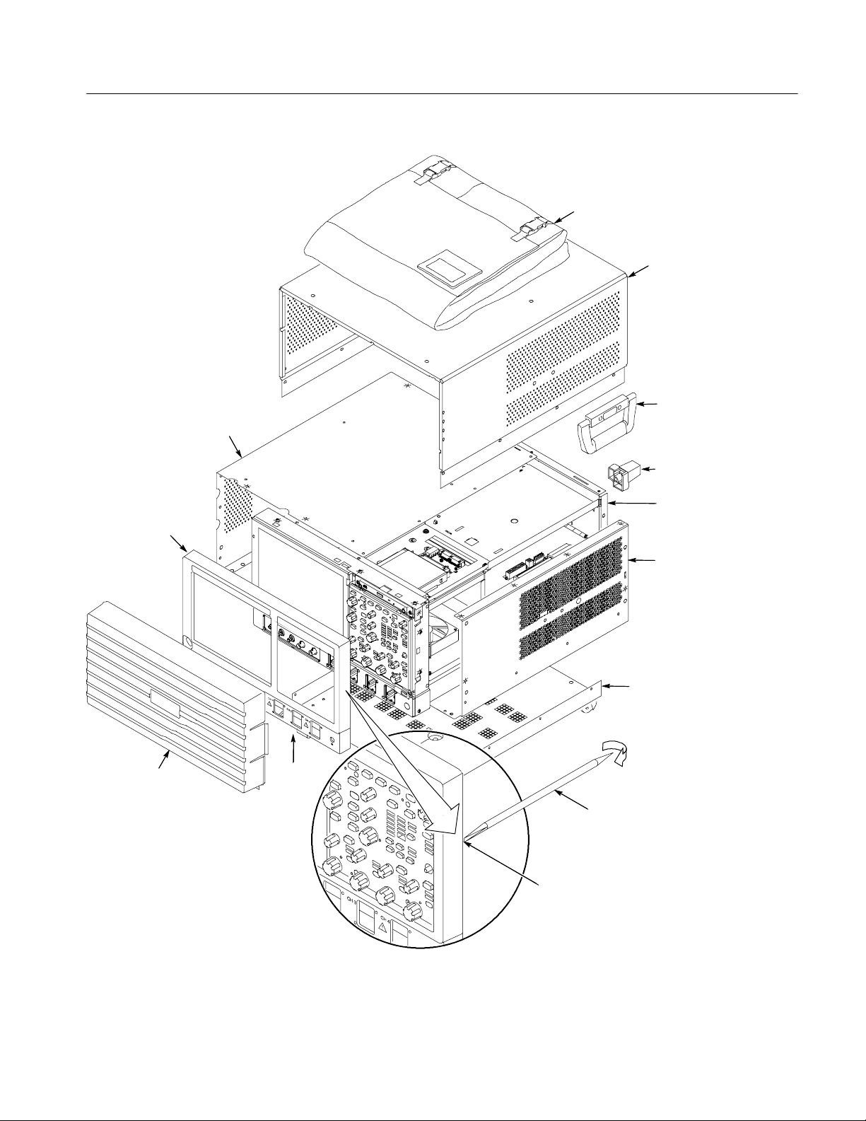
Pouch
Top
cabinet
Carrying
handle
Rear foot
Front
panel trim
Front panel
cover
Chassis
Right side /
bottom cover
Bottom
cabinet
Acquisition
trim
Soldering aid
To remove the trim ring, slide the flat
end of a soldering aid into the side
slot on the trim ring. Press in, lift up
to hook it underneath, then pry out.
Figure 4- 1: Locator for tr im and cabinet removal
TDS6000B & TDS6000C Series Service Manual
4- 11
Removal and Installation Procedures
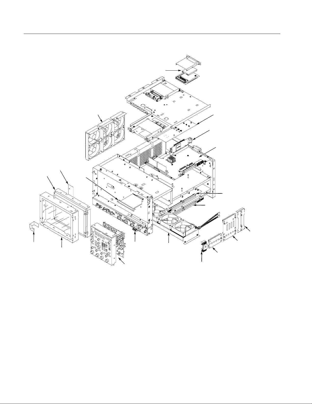
Side fan
assembly
Display
adapter
Display
assembly
board
CD--ROM
drive
Hard disk drive (HDD)
MicroATX board
Bridge board
Power PC (PPC)
processor
Low-voltage
power supply
assembly
Acquisition
board
Power
flex circuit
Touch--
screen
assembly
Figure 4- 2: Locator for internal modules
USB
adapter
Front panel
assembly
Internal fan
assembly
12V AUX
distribution
board
Front
distribution
board
PA bus
board
Rear
distribution
board
4- 12
TDS6000B & TDS6000C Series Service Manual
Removal Procedures
Removal and Installation Procedures
NOTE. Unless directed otherwise, installation is the reverse of the removal
procedure.
These procedures assume you have access to the module you are removing.
Refer to Table 4--4, page 4--9, to determine which trim and/or modules to
remove to gain access, and to direct you to the appropriate exploded drawing.
Figures 4--1 and 4--2, pages 4--11 and 4--12, are also provided as a quick
reference for trim and module locations.
CAUTION. When removing or installing the keypad, make sure you do not touch
the switch contacts with your fingers. The oils in your fingers will degrade or
damage the switch contacts. To help prevent damage to the keypad use cotton
gloves when removing or installing the keyboard pad.
Acquisition Module
MicroATX module
CAUTION. To avoid damage to the front panel Standby/On switch assembly, do
not set the Display module assembly on a work surface. Sliding the oscilloscope
over the edge of the work surface could break off the On/Standby switch
assembly.
The Acquisition module is not field serviceable. Contact the Tektronix service
depot for assistance.
Follow these steps to remove the MicroATX module.
1. Remove the four securing screws from the rear-panel and the three screws
from the side of the MicroATX module.
2. Disconnect the 12V Power Supply cable from J510 on the Power PC (PPC )
module.
3. Disconnect the Power Supply cable from J410 on the PPC module.
4. Gently lift up on the MicroΑΤΧ chassis until the Bridge module disconnects
from the MicroATX module PCI connector.
5. Raise the MicroATX chassis on its hinge, unsnap the prop, and insert the
prop into the retaining slot in the Main chassis side bar.
6. Disconnect the MicroATX cable from J9G1 on the MicroATX module.
TDS6000B & TDS6000C Series Service Manual
4- 13

Removal and Installation Procedures
7. Disconnect the Drive Power cable from J180 on the PPC module.
8. Disconnect the USB cable from J9F2 on the MicroATX module.
9. Raise the MicroATX chassis and snap the prop back into place.
10. Move the MicroATX chassis toward the back of the instrument, to disengage
the hinge, and lift it away from the Main chassis.
Bridge Module
Power PC (PPC)
Follow these steps to remove the Bridge module.
1. Raise the MicroATX module, as described in the previous step.
2. Remove the 10 screws securing the PPC module to the Main chassis.
3. Remove the two jack screws securing the XGA OUT connector to the rear
panel.
4. Remove the two jack screws securing the GPIB connector to the rear panel.
5. Slide the PPC module slightly toward the front of the oscilloscope, until the
XGA OUT connector is clear.
6. Unplug the Bridge module from J870 on the PPC module and lift it out.
Follow these steps to remove the Power PC (PPC) module.
1. Raise the MicroATX module, as described previously.
2. Disconnect and remove the Rear Power Distribution module.
3. Disconnect and remove the PA Bus module.
4. Disconnect the Wide Display cable from J290 on the PPC module.
4- 14
5. Disconnect the Narrow Display cable from J205 on the PPC module.
6. Disconnect the Fan Extender cables from J291 and J390 on the PPC module.
7. Remove the 10 screws securing the PPC module to the Main chassis.
8. Remove the two jack screws securing the XGA OUT connector to the rear
panel.
9. Remove the two jack screws securing the GPIB connector to the rear panel.
10. Slide the PPC module slightly toward the front of the oscilloscope, until the
XGA OUT connector is clear, then lift the PPC and Bridge modules out as a
unit.
TDS6000B & TDS6000C Series Service Manual
Removal and Installation Procedures
CD- ROM Drive
Display
Follow these steps to remove the CD--ROM drive.
1. Remove the two screws securing the CD--ROM bezel, and remove the bezel.
2. Pull the CD--ROM drive out from the Main chassis.
3. Remove the four screws securing the CD--ROM drive and Adapter board to
the CD--ROM drive bracket.
4. Separate the CD--ROM drive and the Adapter board.
Follow these steps to remove the Display module.
1. Remove the four screws securing the display to the Main chassis; two on the
top and two on the left side.
2. Gently remove the Display module from the Main chassis.
3. Disconnect the smaller Display cable from J3 on the Display Adapter board.
4. Disconnect the larger Display cable from J2 on the Display Adapter board.
CAUTION. Be careful when removing and reinstalling the Display module cables.
If the connectors have bent pins or are installed incorrectly the Display may be
destroyed.
Side Fans
Internal Fans
Follow these steps to remove the side fan assembly.
1. Disconnect the fan cables from the fan cable extenders.
2. Unsnap the cable clamps controlling the fan cables.
3. Remove the two screws securing the fan assembly to the Main chassis.
4. Lift the fan assembly up off the tabs on the Main chassis.
Follow these steps to remove the Internal Fan assembly.
1. Remove the two screws securing the internal fan assembly to the Main
chassis.
2. Slide the fan assembly out of the Main chassis.
3. Disconnect the two fan cables.
TDS6000B & TDS6000C Series Service Manual
4- 15

Removal and Installation Procedures
Front Panel
USB Module
Hard Disk Drive
Follow these steps to remove the Front Panel.
1. Remove the six screws that secure the Front Panel to the Main chassis; two
on the top, two on the right side, and two on the bottom.
2. Pull the Front Panel away from the Main chassis.
3. Disconnect the Front Panel cable from P1 on the Front Panel module.
Follow these steps to remove the USB module.
1. Disconnect the USB cable from J1 on the USB module.
2. Remove the one screw securing the USB module to the Main chassis.
3. Lift the USB module from its guide post.
Follow these steps to remove the hard disk drive.
1. Loosen the thumbscrews securing the hard drive to the rear panel.
2. Grasp the hard disk drive assembly by the thumb screws and pull until the
handle is exposed. Grasp the handle and pull the hard drive assembly straight
out of the instrument.
3. Pry the detents retaining the top cover apart, and remove the top cover.
4. Remove the four screws securing the hard drive to the bottom cover.
5. Separate the hard disk drive from the HDD Adapter board.
To replace the hard drive.
1. Connect the hard drive to the HDD Adapter board.
2. Attach the hard drive to the bottom cover with the four screws removed
above.
3. Snap the top cover onto the bottom cover.
4. Leaving the cover/handle extended, push the hard drive assembly into place
until it stops, ensuring that it is straight. Push the hard drive assembly firmly
to ensure that the connector is seated properly.
5. Slide the cover/handle in until it stops. It will be alsmost flush with the back
panel.
6. Finger tighten the two thumb screws to ensure that the removeable hard
drive is properly seated.
4- 16
TDS6000B & TDS6000C Series Service Manual

Troubleshooting
Service Level
WARNING. Before performing this or any other procedure in this manual, read
the General Safety Summary and Service Safety Summary found at the
beginning of this manual.
T o prevent possible injury to service personnel or damage to electrical components, please read Preventing ESD on page 4--1.
This section contains information and procedures designed to help you isolate
faults to a module.
This section assumes that service personnel have the prerequisite skills required
to work on this oscilloscope, including PC troubleshooting and Windows
operating system skills. Details of PC and Windows operation and service are
not in this manual.
For assistance, contact your local Tektronix Service Center.
This subsection contains information and procedures designed to help you isolate
faulty modules in the oscilloscope. If a module needs to be replaced, follow the
Removal and Installation Procedures located in this section.
Check for Common Problems
Use Table 4--5 to quickly isolate possible failures. The table lists problems and
possible causes. The list is not exhaustive, but it may help you eliminate a
problem that is quick to fix, such as a blown fuse or loose cable.
Table 4- 5: Failure symptoms and possible causes
Symptom Possible cause(s)
Oscilloscope will not power on H Power cord not plugged in
Front panel light comes on
(oscilloscope powers on), but
one or more fans will not
operate
H Faulty power supply
H Faulty fan cable
H Defective fan assembly
H Faulty power supply
TDS6000B & TDS6000C Series Service Manual
4- 17

Troubleshooting
Table 4- 5: Failure symptoms and possible causes (Cont.)
Symptom Possible cause(s)
PPC appears “dead”; power
light comes on, but monitor
screen(s) is (are) blank,
oscilloscope emits no beeps
H SO DIMMs incorrectly installed or missing. Missing DIMMs
will cause a POST fault and MicroATX will beep
H Defective Power PC (PPC) board
H Hold down on-standby button on the PPC, if system boots,
replace the power supply
Hard disk drive related
symptoms
CD-ROM related symptoms H Defective CD-ROM
H Improperly seated hard disk drive assembly
H Defective hard disk drive
H Incorrect hard disk type selected in the BIOS setup
H Replaceable hard disk drive not installed
H Power supply failure
H Corrupted BIOS module f irmware, reinstall firmware
H Hard disk drive not configured as bootable (slave) master
hard disk drive
H Loose cable
H Faulty bridge board
H Faulty PPC board
H Defective CD-ROM drive cable
H Defective CD-ROM board
H Incorrect CD-ROM configuration in the BIOS setup
4- 18
TDS6000B & TDS6000C Series Service Manual

Troubleshooting
Table 4- 5: Failure symptoms and possible causes (Cont.)
Symptom Possible cause(s)
Flat panel display blank H Display selection jum per set incorrectly on front panel
board (there are no jumpers on the board when the
oscilloscope is shipped from the factory; this i s the correct
default setting)
H Video adapter set to Integrated (connect monitor to
MicroATX VIDEO port, enter BIOS, set Video Adapter =
PCI)
H BIOS setting not Advance > Video Configuration > Primary
Video Adapter = PCI
H Defective cable from front panel board to display adapter
board
H Defective cable from inverter board to display adapter
board
H Defective cable from inverter board to backlighting display
lamp
H Defective backlighting display lamp
H Faulty display
H Faulty controller board
H Faulty inverter board
H Faulty display adapter board
BIOS error messages H Refer to the BIOS error m essage tabl es starti ng on
Equipment Required
You will need a digital voltmeter to check power supply voltages, as described
on page 4--22.
Testing might also be required to correct some faults. Under those circumstances,
you will need the test equipment listed in the TDS6000B & TDS6000C
Specifications and Performance Verification Technical Reference, available on
the documentation CD--ROM supplied with your instrument, or on the Web at
www.tektronix.com.
Fault Isolation Procedure
Follow the primary troubleshooting tree in Figure 4--3 for fault isolation. This
tree calls for you to run the diagnostics programs, and check for BIOS errors.
page 4--30
TDS6000B & TDS6000C Series Service Manual
4- 19

Troubleshooting
Start
Turn on power
Oscilloscope
powers on
(fans run)?
Yes
Oscilloscope appears
“dead” (dead screen)?
No
Flat-panel
display OK?
Yes
External
monitor
blank, if
present?
No
Possible cause:
1 Oscilloscope power
cord is not plugged in
No
2DoChecking Power
Yes
Beeps
Supply Voltages on
page 4--21
No
Install XGA
No
monitor to
XGA port
XGA OK.
No
Bad PPC, DA, bridge, or
inverter board. Loose
connections
Bad MicroATX, PPC, or bridge board
Yes
Possible cause:
1 Monitor cable defective or not
connected to oscilloscope
2 External monitor controls
turned down
3 Defective monitor
Possible cause:
1 SO DIMMs incorrectly
Yes
Yes
installed or missing
2 Defective controller
board
3 Check beep codes on
page 4--31
Move monitor
to VIDEO
BIOS setting, bad
PPC or bridge
XGA OK.
port.
board
Yes
No
Windows
Boots?
No
Yes
Run CheckIt Utilities
(see CheckIt Utilities
on page 4--27)
Passes all
tests?
No
Yes
Run oscilloscope diagnostics (see
page 4--28 for instructions)
Passes all
tests?
No
Yes
If the oscilloscope Application is not
already running, start it from the
Start menu.
Oscilloscope
Application
starts?
No
Yes
Done
1 See If the Oscilloscope
Will Not Boot on
page 4--24.
2 See Booting Into
Windows on page 4--24.
3 Boot to Safe Mode and
restore the registry.
4 Consult the
troubleshooting section
of your Microsoft
Windows manual
5 See Troubleshooting
Using Reset Circuits on
page 4--34.
Note: It is normal for
CheckIt Utilities to report
an audio failure.
Repair/replace failed part
identified by CheckIt
Utilities
1
Acquisition board
defective
Reinstall oscilloscope
software (see user
manual)
Do If the Oscilloscope
Application Does Not
Work on page 4--24
BIOS error
message?
Yes
See BIOS error
code, Table 4--10
on page 4--30
No
Figure 4- 3: Primary troubleshooting tree
4- 20
1
If only error is error code 512, run SPC after
warmup and then re--run diagnostics.
TDS6000B & TDS6000C Series Service Manual

Troubleshooting
Checking the Power
Supply Voltages
First, make a visual check. As viewed from the right side of the oscilloscope,
there are 11 LEDs on the power supply, which can be seen through the side panel
(see Figure 4--4). DS10 and DS11 are the Global Power indicators, DS3 is the
Standby indicator. When mains power is applied DS10 and DS11 will be on
(green). When the oscilloscope is in standby mode, DS3 will be on (red). When
the oscilloscope is switched to Operate mode, the red standby light will go off
and the remaining LEDs should turn on (green). If DS3 (red) comes on while the
oscilloscope is on, it indicates an overcurrent condition. Table 4--6 shows what is
indicated by the other LEDs.
DS7 DS6 DS1 DS8 DS9 DS4 DS2 DS5
Figure 4- 4: Low voltage power supply LED locations
Table 4- 6: LVPS LED descriptions
LED Voltage LED Indicates
DS1 -- 5 V Good to ACQ board
DS2 +3.3 V Good to PPC, ATX, and ACQ boards
DS4 +5 V Good to PPC, ATX, and ACQ boards
TDS6000B & TDS6000C Series Service Manual
DS10 DS11 DS3
4- 21

Troubleshooting
Table 4- 6: LVPS LED descriptions (Cont.)
LED LED IndicatesVoltage
DS5 +12 V Good to PPC and ATX boards
DS6 +12 V Aux 1 Good to ACQ bd. regulators
DS7 +12 V Aux 2 Good to ACQ bd. regulators
DS8 +15 V Good to ACQ board
DS9 -- 1 5 V Good to ACQ board
1
Becomes +2.6 V Demux supply.
1
1
4- 22
Low voltage power supply LEDs are near the
center of the power supply. A glow from them
is visible while looking through the side of the
Oscilloscope
Figure 4- 5: Location of power-on and over current LEDs
To check the power supply voltages, power on the oscilloscope and connect the
reference lead of a digital voltmeter to chassis ground.
Attach a 0.025 inch square pin to the probe tip of the other lead and insert it into
a pin on one of the connectors. The pins that should be carrying voltages are
listed in Table 4--7. The location of the J1 and J2 connectors is shown in
Figure 4--6 on page 4--23.
Measure the power supply voltages with the voltmeter and compare each reading
to the values listed in the tables. If the voltages are within about 5% of the
nominal voltages, your power supply is functional.
TDS6000B & TDS6000C Series Service Manual

Table 4- 7: Power supply voltages
Auxiliary power
distribution
board (P3) and
Power supply
(J3)
Voltage
Front power distribution board
(P2) and Power
supply (J2)
Voltage
Troubleshooting
Rear power distribution board
(P1) and Power
supply (J1)
Voltage
Pins A/B/C1, 2, 3,
9, 10, 11
+12 V Pins A/B/C1, 2, 3,
4, 7, 8, 11, 12, 13,
+5 V Pins A/B/C9, 10,11+12 V
14
Pins D1. 11 +6 V Pins A/B/C16, 17,
18, 21, 22, 23, 26,
-- 5 V Pins A/B/C14, 15,
16, 19, 20, 21, 22
27, 28, 29
PinsD2,3,9,10 +12 V Pins A31, 32 +15 V Pins A/B/C25, 26,
27, 30, 31, 32
Pins E1, 11 +3 V Pins C31, 32 -- 1 5 V
PinsE2,3,9,10 +12 V
J1 and P1
+3 V
+5 V
Figure 4- 6: Connectors J1, J2, and J3
TDS6000B & TDS6000C Series Service Manual
J2 and P2
PA bus
circuit board
Rear distribution
board
Front distribution
board
12VAUX
distribution board
4- 23

Troubleshooting
If the Oscilloscope Will
Not Boot
Booting Into Windows
If there is a display on the XGA port, but not on the LCD, the oscilloscope may
be in safe mode. Reboot the oscilloscope to clear this condition. If this does not
fix the problem, then replace the display assembly (LCD, lamps, and cable).
At boot time, and while using an external monitor connected to the MicroATX
external video port, press F2 to enter the BIOS setup. The Advanced Video
Configuration menu lets you select PCI (LCD) or Integrated (the MicroATX
VIDEO port on the rear panel). The lower XGA port on the rear panel is the PCI
video port (driven by the same video controller as the LCD).
If the oscilloscope will not boot, run the CMOS restore utility (see Update/Restore the MicroATX Board CMOS on page 4--36).
If booting starts, finds the hard disk, but hangs displaying the Windows splash
screen:
1. Select the Integrated video port using the setup menu.
2. Disable the busses and disconnect the PPC board by installing J114 and J115
(see Figure 4--9, page 4--36).
3. If the system boots (It will only boot to Windows, the oscilloscope application will not run) to the external MicroATX video port, replace the PPC
bridge board.
If the Oscilloscope
Application Does Not
Work
If the oscilloscope boots into Windows, but the oscilloscope application does not
work (the initial splash screen is displayed), check the following:
1. The application software.
2. The Acquisition board.
3. The PPC board.
4. Did someone exit the application using the Task Manager and then try to
reenter the application without rebooting?
5. Check the desktop properties (right click on the desktop and select Properties). On the Settings tab, 16 bit is required. Video merge will not work with
other settings. If you change the setting, reboot.
6. On the Settings tab of the desktop properties, select Advanced and then the
Performance tab. Hardware Acceleration must be set to Full for video merge
to work. If you change the setting, reboot.
4- 24
TDS6000B & TDS6000C Series Service Manual

PPC and MicroATX PC Diagnostics
y
The primary diagnostics for the oscilloscope are the power-on diagnostics, the
CheckIt Utilities diagnostics, and the oscilloscope diagnostics. Procedures for
running these diagnostics are described next.
Troubleshooting
Power-on Diagnostics
The power-on diagnostics check the basic functionality of the oscilloscope at
every power on. If any failures occur at power on, the screen displays the
calibration and diagnostics property page. Table 4--8 lists a subset of the power
on tests. Use the results of the tests to help you isolate problems to system
modules.
The power on tests ensure that hardware is installed and can be accessed by the
software. The tests provide limited diagnostic information, but do not provide
any performance information. The oscilloscope diagnostics provide more
extensive tests than the power-on diagnostics.
The power on tests check the generic hardware including the keyboard, mouse,
memory, CPU, and associated peripherals. The interrupt lines and trigger lines
are also checked.
If there are no failures, you can view the results of the tests in the Instrument
Diagnostics page under the Utilities menu.
Table 4- 8: Power-on diagnostic tests
Component Group&test Error Codes Power on Extended
Mainframe VTC Reset Test n
VTC Walk1 Test n
ADG Register Test n
ADG VXI Addr Test n
ADG VXI Data Test n
System Interrupt Lines n n
Trigger Lines n n
Processor Memory 111 DRAMWalk1
112 DRAMCell
113 DRAMMarch
114 NVRAM
n
PCI Bus 121 Scan Test n
TDS6000B & TDS6000C Series Service Manual
4- 25

Troubleshooting
Table 4- 8: Power-on diagnostic tests (Cont.)
Component ExtendedPower onError CodesGroup&test
RegAccess Ch1 Serial 211 AtoD
212 DAC
213 Preamp
Ch2 Serial 221 AtoD
222 DAC
223 Preamp
Ch3 Serial 231 AtoD
232 DAC
233 Preamp
Ch4 Serial 241 AtoD
242 DAC
243 Preamp
Direct R/W 251 Demux
252 DSY
253 SBTL
254 SGTL
IIC 261 AckIdle
262 Pogo_U1
263 U1350
Relays 271 Interrupt
272 Overloads
273 ShiftLoop
Serial 281 PA_unique
282 PLL
283 TH_IDs
284 TH_unique
285 Trigger DAC
286 U1500
287 U2000
n
n
n
n
n
n
n
n
4- 26
TDS6000B & TDS6000C Series Service Manual

Table 4- 8: Power-on diagnostic tests (Cont.)
Component ExtendedPower onError CodesGroup&test
Troubleshooting
Acquisition DemuxMem 311 MemData
312 MemAddr
313 DMA Read
314 DMA Write
315 FIR
Demux 321 RunAB
322 AcqDone
323 Xfer
324 ICD Bus
325 Intrlv
326 XYtest
327 FIR
Vertical 331 ADC Connects n
Interrupt 341 Bit Tests n
HF Step 351 PhaseCal n n
PLL 361 Clock Freq n
Acq Modes 371 HiRes
372 Peak Detect
373 SubSample
Memory 381 DataFormat
382 MemSpeed
Trigger Inputs 411LineStarted
412 CH1 started
413 CH2 started
414 CH3 started
415 CH4 started
416 Events
417 Comm
n
n
n
n
n
Internals 421 BTrig
Nibble 471 Bus n
Misc Cal Integrity 511 Factory Cal
GPIB 521 Interface n
CheckIt Utilities
If the oscilloscope passes all the BIOS tests and Windows boots, the primary tree
calls for you to run CheckIt Utilities diagnostics software. CheckIt Utilities is a
comprehensive diagnostic software application to check and verify the operation
of the PC hardware in the oscilloscope.
TDS6000B & TDS6000C Series Service Manual
n
422 BTrigEvents
423 TimeInterp
424 Holdoff
425 TrigInfo
n
512 SPC (run SPC)
4- 27

Troubleshooting
CheckIt Utilities. To run the CheckIt Utilities, you must have either a working
keyboard, a pointing device (mouse), and WindowsXP must be running. Before
starting the utilities install a test floppy disk in the floppy disk drive and a test
CD in the CD-ROM drive. Refer to the CheckIt Utilities online help for
additional information on running the utilities. Repair or replace any failed
component identified by the CheckIt Utilities.
Oscilloscope Diagnostics. If the oscilloscope passes all the CheckIt Utilities tests,
the primary tree calls for you to run the oscilloscope extended diagnostics. The
oscilloscope Diagnostics are a comprehensive software test that checks the
functionality of the oscilloscope. If the oscilloscope Diagnostics test fails, the
oscilloscope is defective.
Diagnostics
Software Updates
The oscilloscope has two levels of internal diagnostics that focus on verifying,
adjusting, and if need be, isolating faulty modules.
Both levels of internal diagnostics report any defective modules. If a defective
module is found, replace the module.
The two levels of diagnostics are the short confidence set and the extended set
that tests the oscilloscope circuitry in depth and takes more time. At power on,
the oscilloscope automatically executes the short set. The extended set is
optional and is executed by using the following procedure:
Prerequisites: Power on the oscilloscope and allow a 20 minute warm-up before
doing this procedure.
1. Turn off all other applications.
2. From the menu bar, touch Utilities and then select Instrument Diagnostics.
Software updates are easy to do. Simply install the firmware CD in your
oscilloscope and follow the displayed instructions or the instructions that
accompany the CD.
4- 28
Firmware updates are available for download at no charge from the Tektronix
web site. To find available software updates for your oscilloscope, go to
www.tektronix.com/software and enter your oscilloscope’s model number as
keyword. Updates are also available on CD. If you want to order a software
update on CD, contact your Tektronix service center.
TDS6000B & TDS6000C Series Service Manual

After Repair
Troubleshooting
After removal and replacement of a module due to electrical failure, you must
perform the adjustment or software update as indicated in Table 4--9.
Table 4- 9: Action required for m odule replaced
Adjustment
Module replaced
Front panel assembly No None
Acquisition board Yes
PPC Processor board No
MicroATX processor assembly
Same version
Updated
Display panel or display system No None
Power supply Yes None
Interconnect boards No None
Fans No None
Hard drive
New
Spare
1
Adjustment must be performed by Tektronix.
2
Replacement of this board must be performed by Tektronix.
3
Run SPC after the oscilloscope warms up.
required
No
No
No
No
1
2
3
Software update required
None
Installation by Tektronix is
required
None
Windows,
oscilloscope application
Windows,
oscilloscope application,
optional software applications,
run SPC after warmup
Run SPC after warmup
BIOS Error Messages
When the MicroATX board powers-on, the BIOS runs power-on-self-tests
(POST) to check the board. The BIOS writes error codes to location 80h and
tries to write the codes to the display. If the error is fatal, then the POST code
indicates the last successful checkpoint reached. Table 4--10 lists the error
messages displayed by the BIOS.
Once the display is enabled, errors are written to the display as text messages.
These messages are always displayed unless the board is configured for silent
boot or headless (no keyboard, mouse, or display) operation.
TDS6000B & TDS6000C Series Service Manual
4- 29

Troubleshooting
Table 4- 10: BIOS Error messages
Error message Description
GA20 Error Error when switching to protected mode during the memory test.
Pri Master HDD Error, Pri Slave HDD Error
Sec Master HDD Error, Sec Slave HDD Error
Pri Master Drive -- ATAPI Incompatible
PRI Slave Drive -- ATAPI Incompatible
Sec Master Drive -- ATAPI Incompatible
Sec Slave Drive -- ATAPI Incompatible
A: Drive Error No response from drive.
Cache Memory Bad Memory may be bad.
CMOS Battery Low Replace battery.
CMOS Display Type Wrong Check Setup to make sure type is correct.
CMOS Checksup Bad Run Setup to reset values.
CMOS Settings Wrong Settings corrupted or the battery has failed.
CMOS Date/Time Not Set Run Setup to correct values.
DMA Error Error during read/write test of controller.
FDC Failure Error while trying to access controller.
HDC Failure Error while trying to access controller.
CheckingNVRAM.... NVRAM is being checked.
Update OK! Invalid NVRAM has been updated.
Updated Failed Unable to update invalid NVRAM.
Keyboard Error Make sure keyboard is connected properly.
KB/Interface Error Keyboard test failed.
Memory Size Decreased If no memory was removed, the memory may be bad.
Memory Size Increased If no memory was added, system may have a problem.
Memory Size Changed If no memory was added or removed, the memory may be bad.
No Boot Device Available Boot device not found.
Off Board Parity Error Parity error occurred on an off-board card.
On Board Parity Error Parity error occurred in on-board memory.
Parity Error Error occurred in on-board memory at an unknown address.
NVRAM/CMOS/PASSWORD cleared by Jumper Turn off power and remove the jumper.
<CTRL_N> Pressed CMOS is ignored and NVRAM is cleared. Enter Setup.
Could not read sector.
Drive not an ATAPI device. Run Setup, and maker sure device is
set up correctly.
4- 30
TDS6000B & TDS6000C Series Service Manual

BIOS Beep Codes
Troubleshooting
When the MicroATX board powers-on a number of the BIOS checkpoints
generate an audible ‘beep’ code on failure using the standard PC speaker (also
routed through the board audio system). The beep codes are listed in Table 4--11.
Codes are also written to I/O port 80h and the video adapters. External ROM
modules may issue a series of tones on error detection.
The BIOS generates one short beep if the power up self tests complete without
error.
If your instrument does not contain a speaker, attach a speaker to the displayadapter board square pins to hear the codes.
Table 4- 11: Beep codes
Beep code Error message
1 Refresh failure
DIP Switch Controls
2 Cannot reset parity
3 Memory failure, first 64 KB
4 Timer failure
5 Not used
6 Cannot toggle 8042 GateA20
7 Exception interrupt error
8 Display memory R/W error
9 Not used
10 CMOS Shutdown register test error
11 Invalid BIOS
1 long, 1 short Video configuration failure, or external ROM module checksum error
DIP switches (see Figure 4--9 on page 4--36) are used to direct program flow
during power on self test (POST) of the power PC (PPC). A switch set to ON is
closed and presents a low state (0 V) to the switch buffer. This is the default
switch position. A switch set to OFF is open and presents a high state (3.3 V) to
the switch buffer. This is the ‘set’ position. Table 4--12 describes the switch
functions.
TDS6000B & TDS6000C Series Service Manual
4- 31

Troubleshooting
Table 4- 12: DIP switch functions
Test option
Switch
1 1 Meg RAM test 32 Meg RAM test POST cannot determine how much
2 Enable phase 2 POST Disable phase 2 POST Use to disable phase 2 of POST.
3 Do not loop on phase 2 POST Loop on entire phase 2 POST This switch is checked at every loop
4 Allow debug output Suppress debug output Used by the console. Checked at every
5 Loop on failing test Continue past failing test If a test fails (except DRAM march test)
6 Stop on failing test Continue past failing test If set and a test fails, the program
7 Do not cycle application diagnostics Application diagnostic cycle If set, the power-on diagnostics cycle,
Default
Set Description
DRAM is installed in the board.
iteration, so it is possible to break out
of this loop by moving switch 3 to the
default position. You cannot loop on a
single passing test.
write operation.
and switch 6 is set, this switch is
checked. You can break out of the loop
by moving switch 5 to the set position,
removing the fault, or by setting switch
6 to the default position.
checks switch 5. If not set, the program
will stop on a failure by branching to a
loop. To exit the loop, reset the power
PC.
which prevents completion of the boot
sequence.
8 Do not force power-up diagnostics Forces power-up diagnostics At power-on this switch is checked, and
if set, power-up diagnostics will run.
Diagnostic LED
Table 4--13 lists the actions performed at power-up of the power pc (PPC) and
the associated display on the diagnostic LED. See Figure 4--9 on page 4--36 for
the location of the Diagnostic LED (DS320). Until the MPC106 is initialized the
LED is not active. RESET forces the display to 8. H, L, P, and a blinking -indicate where the program is in the power-up sequence. As tests occur, the
associated number is displayed on the LED. A failing test displays a decimal
point and the test number.
4- 32
TDS6000B & TDS6000C Series Service Manual

Table 4- 13: Diagnostic LED
Diagnostic status
Troubleshooting
LED
8. MPC740 initialization,
0 MPC740 initialization,
1 First PCI access test and
2 PC87560 walking-one PC87560 configuration Request vendor/device identifier. Data 0x0face560 is written to
Passed test
MPC106 walking one test, or
MPC106 configuration test
UART initialize
Testing Test method
Walk a one through configuration register. Use addresses
MPC106 walking one test, or
MPC106 configuration test
First PCI access test and
UART initialize
PC87560 walking-one Walk a one through the configuration register. Walk a one
FEC00000 and FEE00000. A one is walked through the lower
data bus.
Requests the vendor identifier. Use addresses FEC00000 and
FEE00000. Vendor identifier data is presented on the lower
data bus. Data 0x0face106 is written to the MPC740 register
gpr2 if the correct vendor identifier is returned. If the incorrect
identifier is returned, data 0x01bad106 is written to the
register.
This is not a pass/fail test, only an attempt to read the PCI
bus. Read the configuration space of the SIO. The SIO should
return the vendor/device identifier (0x00021057), within
MPC740 gpr2 register. No data comparison or fault
determination occurs. DIP switches are not checked.
Set UART to 9600, n, 8, 1. No testing or fault reporting is
performed. Once completed, console is usable. Dip switches
are not checked.
through the AD bus.
MPC740 register gpr6 if correct identifier is returned. If
incorrect identifier is returned, data 0x01bad560 is written to
MPC740 register gpr6.
3 PC87560 configuration DEC21554 configuration Request vendor/device identifier. Data 0x0face215 is written to
MPC740 register gpr6 if correct identifier is returned. If
incorrect identifier is returned, data 0x01bad215 is written to
MPC740 register gpr6.
4 DEC21554 configuration RS232 interface test Send UUUUUUUU (55hex, 1010101 binary) to console.
5 RS232 interface test ROM checksum Calculate device checksum and compare with checksum in
ROM.
6 ROM checksum DRAM cell test with cache Test address lines. Write patterns to address range set by
switch 1. From start address (000000000) to end address,
write hex pattern aaaaaaaa. Repeat for hex patterns cccccccc
and f0f0f0f0.
7 DRAM cell test with cache DRAM march test without
cache
8 DRAM march test without
cache
9 DRAM march test with cache DRAM walking one Test data lines. Walk a one through DRAM memory location.
A DRAM walking one NVRAM walking one Walk a one through NVRAM memory location. Cache is
H POST passed
DRAM march test with cache Test data lines. Write to address range set by switch 1.
DRAM march test. Test data lines. Write to address range set
by switch 1. Cache is disabled.
Cache is disabled. Walk a one through buss MEM_DL.
disabled. Walk a one through bus XPC_ISA_D.
TDS6000B & TDS6000C Series Service Manual
4- 33
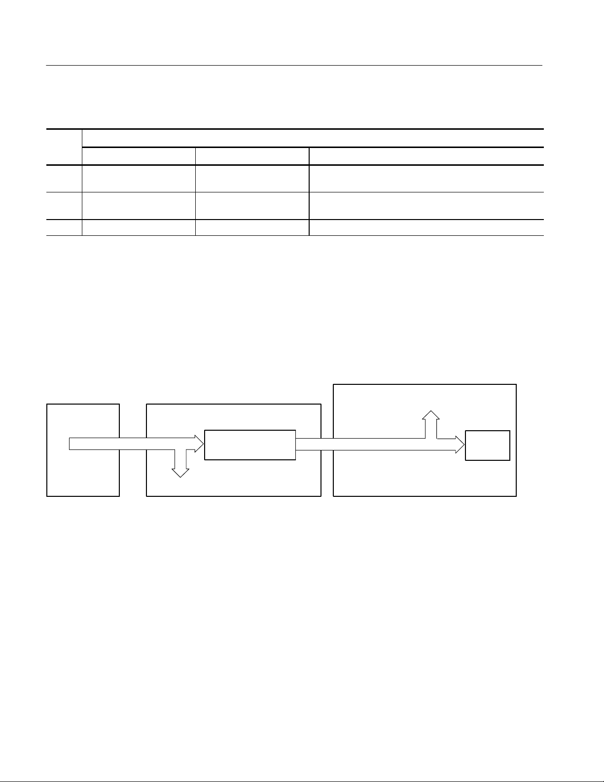
Troubleshooting
Table 4- 13: Diagnostic LED (Cont.)
Diagnostic status
LED
LED
L Boot parameters loaded and
waiting for host
P Loading files from host Program has connected to host and is loading oscilloscope
— Load process complete Files have completed loading.
Test methodTestingPassed test
Program has loaded boot parameters and is waiting to
connect to host.
files.
Troubleshooting Using Reset Circuits
The Power PC (PPC) board uses a combination of removable jumpers and
surface mount resistors to manipulate circuit reset for troubleshooting.
There are three PCI busses on the PPC board, the MicroATX primary PCI bus,
L2 PCI bus, and the embedded PPC PCI bus. A hardware fault on any of these
busses can prevent Windows from starting properly.
PPC (Oscilloscope)
MicroATX
(Windows)
MicroATX Primary PCI Bus
Bus 0
Bridge
J115
J114
Transparent Bridge
Bus 1
Drawbridge
Tvia Video Adapter
Figure 4- 7: The three PCI busses
4- 34
Using jumpers J114 and J115 (see Figure 4--9 on page 4--36) you can selectively
remove components from the MicroATX primary PCI bus. This is useful when
Windows will not start. The Bridge board components on the MicroATX primary
PCI bus are the Intel 21152 transparent bridge, and the Tvia CP5202 video
adapter.
Installing J114 forces the transparent bridge, all components on the L2 PCI bus,
and all components on the PPC PCI bus into reset. If this allows Windows to
start, you will need to eliminate the PPC PCI bus. The easiest way to force the
PPC PCI bus into reset is to press and hold the PPC reset button, S100. So,
adding jumper J114, and holding the reset button, determine if the instrument
will boot to Windows.
TDS6000B & TDS6000C Series Service Manual

Troubleshooting
Installing J115 removes the Tvia video adapter from the Windows side. Note,
neither the Bridge board XGA port or the LCD will function if J115 is installed.
Use the MicroATX VIDEO port (see Figure 4--8).
NOTE. The Tvia video adapter located on the Bridge board is the primary video
adapter. A second video adapter is located on the MicroATX board. The second
adapter is an Integrated MicroATX video adapter and the Tvia video adapter is
a PCI bus video adapter. The Tvia adapter is made the primary video adapter
because it can drive LCD panels. Tektronix forces the Tvia adapter to be the
primary video adapter via BIOS setting Advance→ Video C onfiguration→
Primary Video Adapter = PCI.
Oscilloscope video
from Bridge board.
Same as LCD
Figure 4- 8: PCI and MicroATX video connect ors
MicroATX VIDEO
(Windows only)
TDS6000B & TDS6000C Series Service Manual
4- 35

Troubleshooting
Reset
button
J115
DIP switches
S210
J114
On/Stdby
debug button
Diagnostic LED
DS320
Figure 4- 9: Switch, jumper, and reset button locations
Update/Restore the MicroATX Board CMOS
If the CMOS parameters become corrupted, restore the CMOS memory using
one of the following procedures:
CAUTION. Install only CMOS parameters from Tektronix. CMOS parameters
from other manufacturers may make your oscilloscope inoperable.
If you cannot restore the CMOS memory, replace the battery.
Restore the CMOS as follows:
1. Press the F2 key during reboot to enter the BIOS SETUP UTILITY.
2. In the BIOS SETUP UTILITY, press the F9 key.
3. Press the Enter key to Load Optimal Defaults.
4. In the BIOS SETUP UTILITY, press the F10 key.
5. Press the Enter key to Save configuration changes and exit.
4- 36
TDS6000B & TDS6000C Series Service Manual

Installing an Authorization Key
If you replace your PPC board you will need to reinstall the authorization key
(keycode) to return the previous configuration. The keycode for the current
configuraiton is printed on the rear panel label for reference.
If you purchase new options, you will receive a new keycode to activate the new
configuration.
Install the authorization key using the following procedure:
1. From the oscilloscope menu bar, touch the Utilities menu, select Option
Installation, and then touch Continue.
2. Enter the new key using an attached keyboard.
3. Touch Continue.
Troubleshooting
TDS6000B & TDS6000C Series Service Manual
4- 37

Troubleshooting
4- 38
TDS6000B & TDS6000C Series Service Manual

Repackaging Instructions
This section contains the information needed to repackage the oscilloscope for
shipment or storage.
Packaging
When repacking the oscilloscope for shipment, use the original packaging. If the
packaging is unavailable or unfit for use, contact your local Tektronix representative to obtain new packaging.
Seal the shipping carton with an industrial stapler or strapping tape.
Shipping to the Service Center
Contact the Service Center to get an RMA (return material authorization)
number, and any return or shipping information you may need.
If the oscilloscope is being shipped to a Tektronix Service Center, enclose the
following information:
H The RMA number.
H The owner’s address.
H Name and phone number of a contact person.
H Type and serial number of the oscilloscope.
H Reason for returning.
H A complete description of the service required.
Mark the address of the Tektronix Service Center and the return address on the
shipping carton in two prominent locations.
TDS6000B & TDS6000C Series Service Manual
4- 39

Repackaging Instructions
4- 40
TDS6000B & TDS6000C Series Service Manual

Replaceable Mechanical Parts


Mechanical Parts List
This section contains a list of the replaceable modules for the oscilloscope. Use
this list to identify and order replacement parts.
Parts Ordering Information
Replacement parts are available through your local Tektronix field office or
representative.
Changes to Tektronix instruments are sometimes made to accommodate
improved components as they become available and to give you the benefit of
the latest circuit improvements. Therefore, when ordering parts, it is important to
include the following information in your order.
H Part number
H Instrument type or model number
H Instrument serial number
H Instrument modification number, if applicable
Module Servicing
If you order a part that has been replaced with a different or improved part, your
local Tektronix field office or representative will contact you concerning any
change in part number.
Modules can be serviced by selecting one of the following three options. Contact
your local Tektronix service center or representative for repair assistance.
Module Exchange. In some cases you may exchange your module for a remanufactured module. These modules cost significantly less than new modules and
meet the same factory specifications. For more information about the module
exchange program, call 1-800-833-9200, select option 2.
Module Repair and Return. You may ship your module to us for repair, after which
we will return it to you.
New Modules. You may purchase replacement modules in the same way as other
replacement parts.
TDS6000B & TDS6000C Series Service Manual
5- 1

Mechanical Parts List
Using the Replaceable Parts List
This section contains a list of the mechanical and/or electrical components that
are replaceable for the oscilloscope. Use this list to identify and order replacement parts. The following table describes each column in the parts list.
Parts list column descriptions
Column Column name Description
1 Figure & Index Number Items in this section are referenced by component number.
2 Tektronix Part Number Use this part number when ordering replacement parts from Tektronix.
3 and 4 Serial Number Column three indicates the serial number at which the part was first effective. Column four
indicates the serial number at which the part was discontinued. No entries indicates the part is
good for all serial numbers.
5 Qty This indicates the quantity of parts used.
6 Name & Description An item name is separated from the description by a colon (:). Because of space limitations, an
item name may sometimes appear as incomplete. Use the U.S. Federal Catalog handbook
H6-1 for further item name identification.
7 Mfr. Code This indicates the code of the actual manufacturer of the part. (Code to name and address cross
reference is located after this page.)
8 Mfr. Part Number This indicates the actual manufacturer’s or vendor’s part number.
Abbreviations
Mfr. Code to Manufacturer
Cross Index
Abbreviations conform to American National Standard ANSI Y1.1--1972.
The following table cross indexes codes, names, and addresses of manufacturers
or vendors of components listed in the parts list.
Manufacturers cross index
Mfr.
code
00779 AMP INC. CUSTOMER SERVICE DEPT
01295 TEXAS INSTRUMENTS INC SEMICONDUCTOR GROUP
01KV9 MERIX CORP 1521 POPLAR LANE
01963 CHERRY ELECTRICAL PRODUCTS CO 3600 SUNSET AVENUE WAUKEGAN, IL 60087-- 3214
03ZT7 MOBILE PLANET 9175 DEERING AVE CHATSWORTH, CA 91311
04713 MOTOROLA INC SEMICONDUCTOR PRODUCTS SECTOR
049S6 FUJITSU COMPUTER PRODUCTS OF
Manufacturer Address City, state, zip code
HARRISBURG, PA 17105--3608
PO BOX 3608
DALLAS, TX 75272--5303
13500 N CENTRAL EXPRESSWAY
PO BOX 655303
FOREST GROVE, OR 97116
PO BOX 3000
PHOENIX, AZ 85008--4229
5005 E MCDOWELL ROAD
2904 ORCHARD PARKWAY SAN JOSE, CA 95134--2009
AMERICA INC
5- 2
TDS6000B & TDS6000C Series Service Manual

Mechanical Parts List
Manufacturers cross index (cont.)
Mfr.
code
05791 LYN--TRON INC SOUTH 6001 THOMAS MALLEN RD SPOKANE, WA 99204
060D9 UNITREK CORPORATION 3000 COLUMBIA HOUSE BLVD, SUITE 1
20
06666 GENERAL DEVICES PO BOX 39100 INDIANAPOLIS, IN 46239
06915 RICHCO 5825 N TRIPP AVE
P.O. BOX 804238
07416 NELSON NAME PLATE COMPANY 3191 CASITAS AVENUE LOS ANGELES, CA 90039--2410
0ADN8 DELTA PRODUCTS CORP--DPZ 4405 CUSHING PARKWAY FREMONT, CA 94538
0B0A9 DALLAS SEMICONDUCTOR 4350 BELTWOOD PKWY S DALLAS, TX 75244
0GZV8 HUBER & SUHNER INC 19 THOMPSON DRIVE ESSEX JUNCTION, VT 05452--3408
0J9P9 GEROME MFG CO INC PO BOX 737
403 NORTH MAIN
0KB01 STAUFFER SUPPLY CO 810 SE SHERMAN PORTLAND, OR 97214--4657
0KB05 NORTH STAR NAMEPLATE INC 5750 NE MOORE COURT HILLSBORO, OR 97124-- 6474
0KBZ5 Q & D PLASTICS INC 1812 -- 16TH AVENUE
PO BOX 487
12136 PHC INDUSTRIES INC 1643 HADDON AVE
PO BOX 1448
16179 M/A COM INC 1011 PAWTUCKER BLVD.
PO BOX 3295
1AW87 LEWIS SCREW CO. 4300 SOUTH RACINE AVENUE CHICAGO, IL 60609
1DM20 PARLEX CORP 7 INDUSTRIAL WAY SALEM, NH 03079
20944 ANRITSU COMPANY 685 JARVIS DRIVE MORGAN HILLS, CA 95037
22526 FCI/BERG ELECTRONICS INC 825 OLD TRAIL ROAD ETTERS, PA 17319--9769
22670 GM NAMEPLATE INCORPORATED 2040 15TH AVE WEST SEATTLE, WA 98119-- 2783
24931 FCI/BERG ELECTRONICS INC RF/COAXIAL DIV
2100 EARLYWOOD DR
PO BOX 547
26003 MARTEK POWER MDI 4115 SPENCER STREET TORRANCE, CA 90503--2489
26805 M/A COM OMNI SPECTRA INC MICROWAVE CONNECTOR DIV
140 4TH AVE
2K262 BOYD CORPORATION 6136 NE 87TH AVENUE PORTLAND, OR 97220
2W733 BELDEN WIRE & CABLE COMPANY 2200 US HWY 27 SOUTH
PO BOX 1980
32559 BIVAR INC 4 THOMAS ST IRVINE, CA 92718
34649 INTEL CORPORATION 3065 BOWERS
PO BOX 58130
3M099 PORTLAND SCREW COMPANY 6520 N BASIN AVE PORTLAND, OR 97217
46628 LOGITECH INC 6505 KAISER DR FREMONT, CA 94555
50356 TEAC AMERICA INC 7733 TELEGRAPH RD
PO BOX 750
5Y400 TRIAX METAL PRODUCTS INC 1880 SW MERLO DRIVE BEAVERTON, OR 97006
City, state, zip codeAddressManufacturer
VANCOUVER, WA 98661
CHICAGO, IL 60646
NEWBERG, OR 97132
FOREST GROVE, OR 97116--0487
CAMDEN, NJ 08103
LOWELL, MA 01853--3295
FRANKLIN, IN 46131
WALTHAM, MA 02254
RICHMOND, IN 47374
SANTA CLARA, CA 95051-- 8130
MONTEBELLO, CA 90640--6537
TDS6000B & TDS6000C Series Service Manual
5- 3

Mechanical Parts List
Manufacturers cross index (cont.)
Mfr.
code
61058 MATSUSHITA ELECTRIC CORP OF AMERICA PANASONIC INDUSTRIAL CO DIV
TWO PANASONIC WAY
64537 KDI/TRIANGLE CORPORATION 60 S JEFFERSON RD WHIPPANY, NJ 07981
6Y440 MICRON SEMICONDUCTOR PRODUCTS INC 8000 S FEDERAL WAY
PO BOX 6
71400 BUSSMANN DIVISION COOPER INDUSTRIES INC
PO BOX 14460
74594 COMPONENT RESOURCES INC BUSSMAN PARTS
C/O CASEY LAKEY
14525 SW WALKER ROAD
75915 LITTELFUSE INC 800 E NORTHWEST HWY DES PLAINES, IL 60016 --3049
76096 ELMA ELECTRONICS INC 41440 CHRISTY ST FREMONT, CA 94538
78189 SHAKEPROOF DIVISION OF ILLINOIS TOOL WORK
ST. CHARLES ROAD
7X318 KASO PLASTICS INC 5720--C NE 121ST AVE, STE 110 VANCOUVER, WA 98682
80009 TEKTRONIX INC 14150 SW KARL BRAUN DR
PO BOX 500
86928 SEASTROM MFG CO INC 456 SEASTROM STREET TWIN FALLS, ID 83301
8X345 NORTHWEST SPRING MFG CO 5858 WILLOW LANE LAKE OSWEGO, OR 97035
93907 CAMCAR DIV OF TEXTRON INC ATTN: ALICIA SANFORD
516 18TH AVE
94222 SOUTHCO, INC. 210 N BRINTON LAKE RD CONCORDVILLE, PA 19331
99144205BEIJING MINGDAR TECHNOLOGY INC RM 213 LUIPU BLDG, NO 5 XIAGUANGLI,
CHAOYANG DISTRICT
S5769 NEC CORPORATION NEC BUILDING
7--1, SHIBA 5 CHOME
MINATO-- KU
TK0588 UNIVERSAL PRECISION PRODUCT 1775 NW CORNELIUS PASS RD HILLSBORO, OR 97124
TK1163 POLYCAST INC 14140 SW 72ND AVE
SUITE 100
TK1943 NEILSEN MANUFACTURING INC 3501 PORTLAND RD NE SALEM, OR 97303
TK2172 WYLE ELECTRONICS INC 10300 SW NIMBUS AVE
BLDG P, SUITE B
TK2250 ARROW ELECTRONICS INC. 9500 SW NIMBUS AVE, BLDG E BEAVERTON, OR 97008--7163
TK2376 CONDUCTIVE RUBBER TECH 22125 17TH AVE SE, SUITE 117 BOTHELL, WA 98021
TK2491 RIFOCS CORPORATION 1340 FLYNN RD CAMARILLO, CA 93012
TK2548 XEROX CORPOR ATION 14181 SW MILLIKAN WAY BEAVERTON, OR 97005
TK2563 REVTEK INC 4288 SE INTERNATIONAL WAY PORTLAND, OR 97222
TK2582 TUFF CAT USA LLC 814 N HAYDEN MEADOWS DRIVE PORTLAND, OR 97217
TK2601 MAXTEK COMPONENTS CORPORATION 13335 SW TERMAN RD
PO BOX 428
TK2647 INSTRUMENT SPECIALTIES CO IN C. C/O TEMCO NW
1336 SE 51ST STREET
City, state, zip codeAddressManufacturer
SECAUCUS, NJ 07094
BOISE, ID 83707--0006
ST LOUIS, MO 63178
BEAVERTON, OR 97006
ELGIN, IL 60120
BEAVERTON, OR 97077--0001
ROCKFORD, IL 611045181
BEIJING, CN
TOKYO, JP 108
TIGARD, OR 97224
PORTLAND, OR 97223
BEAVERTON, OR 97075--0428
HILLSBORO, OR 97123
5- 4
TDS6000B & TDS6000C Series Service Manual

Mechanical Parts List
Manufacturers cross index (cont.)
Mfr.
code
TK6173 MULTI-- FINELINE ELECTRONIX INC (MFLEX) DBA: MFLEX
1301 N DYNAMICS STREET
TK6181 IMC PLASTICS INC 19400 SW TETON AVE TUALATIN, OR 97062
TK6253 VOLEX INTERCONNECT INC 646 CARRIBEAN DR SUNNYVALE, CA 94089-- 1108
City, state, zip codeAddressManufacturer
ANAHEIM, CA 92806
TDS6000B & TDS6000C Series Service Manual
5- 5

Mechanical Parts List
Replaceable Parts List
Fig. &
index
number
5--1 External Parts
--1 211-- 1050-- 00 35 SCREW, MACHINE; 6-- 32 X 0.312 L, PNH, STL CAD PLT, T15 78189 60--060845--OX
--2 355--0298-- 00 4 STUD. SNAP; 0.570 DIA,0.165 THK, STAINLESS STEEL TK0588 355-- 0298-- 00
--3 016--1441-- 00 1 POUCH; BLACK CORDURA TK6106 016--1441--00
--4 200--4854-- 00 1 COVER, SKIN; OUTER TUCK UNDER, 1WNW6200--4854--00
Tektronix part
number
Serial no.
effective
Serial no.
discont’d
Qty Name & description
Mfr.
code
Mfr. part number
--5 367--0528-- 00 1 HANDLE, CARRYING; DUAL DUROMETER MOLDED,
POLYPROPYLENE,
--6 407--4887-- 00 1 BRACKET; HANDLE BASE, PC/ABS ALLOY, BAYER
BAYBLEND FR--110, TEK BLUE,
--7 212--0232-- 00 2 SCREW, MACHINE; 8--32 X 1.125L, PNH, STL, BLACK ZINK
SPEC #ASTM B633 TYPE II, T20
--8 211-- 0720-- 00 4 SCR, ASSEM WSHR; 6-- 32 X 0.500, PNH, STL, CDPL, T-- 15
TORX DR,MACHINE
--9 348--1648-- 00 4 FOOT; REAR W/CORD WRAP, THERMO PLASTIC 7X318 348--1648--00
--10 161--0104-- 00 1 CABLE ASSY, PW R; 3, 18 AWG, 98.0 L, 125V/10AMP, RIGHT
ANGLE, IEC320, NEMA 15--5P,
--11 200--4941-- 00 1 COVER,BOTTOM; RIGHT,AL,
(TDS6124C/TDS6154C ONLY)
200--4838--00 1 COVER,BOTTOM; RIGHT,AL
(TDS6604B/TDS6804B ONLY)
--12 348--1515-- 00 1 FEET, CABINET; BLACK, GLASS--FIBRE REINFORCED
PLASTIC, SET OF 4 FEET, 4 RUBBER INSERTS,
--13 200--4855-- 00 1 COVER; BLACK, 0.05 AL, VINYL CLAD
(TDS6604B/TDS6804B ONLY)
200--4942--00 1 COVER; BLACK,0.05 AL,VINYL CLAD
(TDS6124C/TDS6154C ONLY)
--14 101--0168-- 00 1 TRIM RING, FRONT 80009 101016800
--15 101--0159-- 00 1 TRIM,INPUT; PLASTIC,BLACK,ABS, TK2565 101-- 0159--00
--16 200--4653-- 00 1 COVER, FRONT; PROTECTIVE, FR110, TEK BLUE 7X318 200-- 4653--00
--17 335--1046-- 00 1 MARKER,IDENT; LABEL,FRONT BNC INPUT, 0KB05 335104600
--18 260--2783-- 00 1 SWITCH, KEYPAD; ELASTOMERIC, FRONT PANEL,
PUSHBUTTON,
--19 335--1305-- 00 1 LABEL;IDENT, TDS6124C
(TDS6124C ONLY)
335--1311--00 1 LABEL;IDENT; TDS6154C
(TDS6154C ONLY)
335--1044--00 1 MARKER,IDENT; LABEL,INDENTIFICATION
(TDS6804B ONLY)
335--1045--00 1 MARKER,IDENT; LABEL,IDENTIFICATION
(TDS6604B ONLY)
--20 200--4839-- 00 1 COVER, TOP; LEFT, AL TK1943 200--4839--00
12136 367--0528--00
TK2565 407--4887--00
0KB01 212023200
78189 60--060845--OX
TK6121 3572WV88.2GI
TK6621 200494100
TK1943 200--4838--00
76096 63--526
1WNW6200--4855--00
80009 200--4942--00
22670 260--2783--00
0KB05 335130500
0KB05 335131100
0KB05 335104400
0KB05 335104500
5- 6
TDS6000B & TDS6000C Series Service Manual

Mechanical Parts List
1
2
3
4
5
6
7
8
9
16
17
19
20
18
10
1
11
14
15
1
1
1
13
Figure 5- 1: External parts
TDS6000B & TDS6000C Series Service Manual
12
5- 7

Mechanical Parts List
Replaceable Parts List
Fig. &
index
number
5--2 Front panel and drives
--1 211-- 1050-- 00 15 SCREW, MACHINE; 6-- 32 X 0.312 L, PNH, STL CAD PLT, T15 0KB01 211105000
--2 679--5705-- 00 1 IDE1 ADAPTER BOARD
--3 441--2320-- 00 1 CHASSIS; DRI VE FRAME,BOTTOM,GAL-- XC,STEEL 80009 441--2320--00
--4 343--1682-- 00 1 CLAMP, HINGED FLAT CABLE (ARROWHEAD BASE), NYLON HFCC-- A-- 8--01
--5 174--4321-- 00 1 CABLE ASSY; FLAT FLEX, 26POS, 10.440L, FRONT PANEL
--6 679--5660-- 00 1 CIRCUIT BD ASSY; USB FRONT PANEL, WIRED 389345000
--7 614--1028-- 00 1 MODULAR ASSY, FRONT PANEL 80009 614-- 1028-- 00
--8 679--5795-- 00 1 CKT BD SUBASSY; FRONT PANEL,W/INTEGRATED
--9 260--2760-- 00 1 SW ITCH,KEYPAD; ELASTOMERIC,FRONT PANEL,PUSH
--10 366--0821-- 00 7 KNOB, CAP; 0.650 D, SOFT FEEL COATING, PC/ABS
--11 366--0819-- 00 1 KNOB,EPS; PUSH BUTTON ENCODER, SOFT FEEL
--12 366--0820-- 00 7 KNOB, CAP; 0.425 DIA,SOFT FEEL COATING, PC/ABS,BAY-
--13 333--4491-- 00 1 PAN EL ASSEMBLY; FRONT SUBPANEL,W/BRACKET
--14 650--4623-- 00 1 TOUCH SCREEN ASSEMBLY; TDS6000C; CSA6000C
--15 259--0155-- 01 1 FLEX CIRCUIT; POWER SWITCH, W/LED
--16 650--4632-- 00 1 DISPLAY ASSEMBLY 80009 650--4632--00
--17 174--4791-- 00 1 CA ASSY; DISPLAY ADAPTER TO XGA DISPLAY, SAFETY
--18 679--5497-- 00 1 DISPLAY ADAPTER; TDS6000C
--19 174--4794-- 00 1 CA ASSY; DISPLAY ADAPTER TO INVERTOR, SAFETY
--20 211--0720--00 2 SCR,ASSEM WSHR; 6--32 X 0.500,PNH,STL,CDPL,T --15
--21 200--4829-- 01 1 COVER; CD 80009 200--4829--01
Tektronix part
number
366--0837--00 7 KNOB,CAP;0.650 DIAMETER,SOFT FEEL COATING
366--0835--00 1 KNOB,EPS;PUSH BUTTON ENCODER, SOFT FEEL
366--0836--00 7 KNOB,CAP;0.650 DIAMETER,SOFT FEEL COATING
Serial no.
effective
Serial no.
discont’d
Qty Name & description
(Connects between J1 on Front Panel and J150 on Power PC
Processor)
ENCODERS,4 CH
BUTTON
BAYBLEND, FR110, TEK SILVER GRAY (TDS6000B Only)
(TDS6000C Only)
COATING, PC/ABS BAYBLEND, FR110, TEK SILVER GRAY
(TDS6000B Only)
(TDS6000C Only)
BLEND, FR110,TEK SILVER GRAY (TDS6000B Only)
(TDS6000C Only)
ASSEMBLY,BEZEL & LABEL
(Connects to J7 on Display Adapter Board)
CONTROLLED
(Connects between J8 on Display Adapter Board and 20--pin
connector on Display)
CONTROLLED
Connects between J5 on Display Adapter Board and CN1 on
ALPS Inverter Board, also on back of Display Assembly)
TORX DR,MACHINE
Mfr.
code
1DM20 174--4321--00
80009 679--5795--00
80009 260--2760--00
22670 366--0821--00
80009 366--0837--00
22670 366--0819--00
80009 366--0835--00
22670 366--0820--00
80009 366--0836--00
80009 333--4491--00
22670 259--0155--01
060D9 174--4791--00
060D9 174--4794--00
80009 211-- 0720-- 00
Mfr. part number
5- 8
TDS6000B & TDS6000C Series Service Manual

Mechanical Parts List
Replaceable Parts List (Cont.)
Fig. &
index
number
--22 119--6839--00 1 DISK DRIVE; OPTICAL, CD-- RW, 5.25 SLIM, IDE, 24X, 24X,
--23 679--5653-- 00 1 CDRW ADAPTER BD; 389--3445-- 00
--24 407--4943-- 00 1 BRACKET; CD--ROM; EG STEEL 1WNW6407--4943--00
--25 211--0950--00 4 SCREW, MACHINE; M2X.4X3L,PHL, PNH, STL NI PL 0KB01 0310248--0
Tektronix part
number
Serial no.
effective
Serial no.
discont’d
Name & descriptionQty
10X, 650/700MB, 110MS; SAFETY CONTROLLED
Mfr.
code
50356 CD-- W224E--A93
Mfr. part number
TDS6000B & TDS6000C Series Service Manual
5- 9

Mechanical Parts List
23
P2
P1
1
J1
P3
2
3
14
P7 to J7
(Display
adapter
board)
15
20
13
21
22
17
16
18
19
24
(top and bottom)
25
Access notches
CH 1
P1
Finger
relief
P2
P5
J5
J6
J4
P1
4
J7
1
1
12
11
10
1
Figure 5- 2: Front panel and drives
5- 10
8
9
7
Black stripe toward
connector
Screwdriver
5
P150 to J150 (Power
PC processor board)
1
6
J1
TDS6000B & TDS6000C Series Service Manual

Mechanical Parts List
Replaceable Parts List
Fig. &
index
number
5--3 Front panel and drives (cont.)
--1 650--4685-- 00 1 MODULAR KIT, REMOVABLE DISK DRIVE ASSEMBLY
--2 200--4829-- 00 1 COVER; CD 80009 200-- 4829-- 00
--3 211-- 1081-- 00 2 SCREW,MACHINE; M3 X 0.5 X 3.5MM,FLAT WAFER HD
--4 407--4945-- 00 1 BRKT SUPPORT, REMOVABLE HD: TOP, GAL--XC; STEEL 1WNW6407--4945--00
Tektronix part
number
650--4759--00 1 REMOVABLE DISK DRIVE ASSEMBLY
Serial no.
effective
Serial no.
discont’d
Qty Name & description
(TDS6804B/TDS6604B Only)
(TDS6000C Only)
W/SERRATIONS STRESS RELIEVED,PHL,0.0002 STL ZI PLT
Mfr.
code
80009 650--4685--00
80009 650--4759--00
80009 211-- 1081-- 00
Mfr. part number
--5 119-- 6832-- 00 1 HARD DISK DRIVE, 40 GB, 2.5 IN, IDE0ATAPI--6, 4200 RPM,
SAFETY CONTROLLED
--6 679--5654-- 00 1 HDD ADAPTER
--7 211-- 1050-- 00 6 SCREW, MACHINE; 6-- 32 X 0.312 L, PNH, STL CAD PLT, T15 0KB01 211-- 1050-- 00
--8 407--4943-- 00 1 BRACKET; CD--ROM; EG STEEL 1WNW6407--4943--00
--9 407--4944-- 00 1 BRACKET; REMOVABLE HD BOTTOM; GAL--XC; STEEL 1WNW6407--4944--00
--10 211--1081--00 4 SCREW, MACHINE; M3 X 0.5 X 3.5MM, F6LAT WAFER HD
W/SERRATIONS, PHL, 0.0002 STL ZI PLT
--11 679--5722-- 00 1 DIAG PA BUS CONNECTOR 80009 679-- 5722--00
--12 679--5723-- 00 1 DIAGNOSTIC REAR POWER DISTRIBUTION, MINUS P11
AND P101; TESTED,389--3045-- 00 WIRED;TDS7000 SERIES
--13 679--5724-- 00 1 CKT BD SUBASSY; 678--1092--00,GPIB INTERFACE 80009 679-- 5724--00
--14 361--1762-- 00 8 SPAC ER,SUPPORT; 0.250 X 0.171 X 0.375,CIRCUIT
BOARD,NYLON CPST--4-- 01
--15 679--5695-- 00 1 CIRCUIT BD ASSY; AUX POWER, WIRED 389347900
--16 174--4871-- 00 2 CABLE ASSY; EXTENSION, SAFETY CONTROLLED 80009 174--4871--00
--17 358--0161-- 05 1 BSHG,STRAIN RLF; U/W 0.29 DIA CABLE,STRAIGHT 80009 1147 SR-- 5P--4
--18 437--0510-- 00 1 TRAY, FAN; FOUR 119--5935--00 FANS; SAFETY CONT-ROLLED
--19 174--4267-- 00 2 CA ASSY; DESCRETE, IDC, FAN TRAY EXTENDER
(Connects between fans and J390 & J291 on Power PC
Processor)
--20 343--1681-- 00 1 CABLE, CLAMP; FLAT; NYLON 80009 343--1681--00
--21 437--0846-- 01 1 FAN ASSEMBLY; 6 FANS (119--5935--00), ASSEMBLED TO
FAN TRAY (436--0373-- 01)W/NYLON RIVETS (210--0164--00),
12.00 X 7.65 X 1.75, SAFETY CONTROLLED
80009 119-- 6832-- 00
0KB01 211--1081--00
80009 679--5723--00
06915 CPST-- 4-- 01
80009 437--0510--00
060D9 174--4267--00
80009 437--0846--01
TDS6000B & TDS6000C Series Service Manual
5- 11

Mechanical Parts List
2
Pry detents (4)
3
7
20
7
19
21
P2
7
J2
5
6
8
9
10
J291
P291
4
1
J390
P390
18
17
Figure 5- 3: Front panel and drives (cont.)
5- 12
13
16
15
14
7
12
11
TDS6000B & TDS6000C Series Service Manual

Mechanical Parts List
Replaceable Parts List
Fig. &
index
number
5--4 Power supply
--1 211-- 1050-- 00 8 SCREW, MACHINE; 6-- 32 X 0.312 L, PNH, STL CAD PLT, T155 0KB01 211--1050-- 00
--2 679--5705-- 00 1 IDE ADAPTER BOARD, HARD DI SK DRIVE
--3 441--2368-- 00 1 CHASSIS ASSY; ATX, SAFETY CONTROLLED 1WNW6441236800
Tektronix
part number
Serial no.
effective
Serial no.
discont’d
Qty Name & description
Mfr.
code
Mfr. part number
--4 214--3903-- 00 2 SCREW, JACK; 4--40 X 0. 312 LONG, 0.188 H HEX HEAD
STAND OFF, 4--40 INT THD, X 0.312 THD EXT 4--40
--5 213--1061-- 00 2 SCREW; JACK; 6--32 X 0.320 EXT THD, M3.5 X 0.6--6 INT
THD X 0.215L, GPIB, BLACK OXIDE
--6 671--5814-- 00 1 CIRCUIT BD ASSY; PROCESSOR,TESTED,389339000 WIRED
(REQUIRES PROGRAMMING AT A TEKTRONIX SERVICE
CENTER)
--7 131--1315-- 01 3 CONN, RF JACK; BNC,PNL, 50 OHM, FEMALE, STR,
0.375--32 THD
--8 650--4604-- 02 1 MODULAR ASSY; POWER SUPPLY 80009 650--4604--02
--9 210--0465-- 00 1 NUT, PLAIN, HEX; 0.25-- 32 X 0.375, BRS CD PL 0KB01 210--0465--00
--10 210--0046-- 00 1 WASHER, LOCK; 0.261 ID, INTL, 0.018 THK 78189 1214--05--00--0541C
--11 136--0140-- 00 1 JACK, TIP; BANANA, CHARCOAL GRAY TK6065 136--0140--00
--12 343--1682-- 00 1 CLAMP, HINGED FLAT CABLE (ARROWHEAD BASE), NYLON HFCC --A--8 --01
--13 174--4792-- 00 1 CA ASSY; DISPLAY ADAPTER TO PPC, SAFETY CONTROLLED
(Connects between J290 on Power PC Processor and J2 on
Display Adapter)
--14 174--4793-- 00 1 CA ASSY; DISPLAY ADAPTER TO BRIDGE, SAFETY
CONTROLLED
(Connects between J205 on Bridge Board and J3 on Display
Adapter)
--15 174--4806-- 00 1 CA ASSY; ATX DRIVE POWER, 24.0 L,4 CONDUCTORS,
SAFETY CONTROLLED
(Connects between J180 on Power PC Processor, P3 on IDE
Adapter -- Hard Disk Drive and P3 on IDE Adapter -- CD-- ROM.
NOTE: All 3 plugs are the same. One is labeled MB, one is
labeled P1 and one is labeled P3.
55566 4750--3--12 (+LOCK-
WASHER)
00779 554043--3
80009 671--5814--00
TK6592 28JR306--1
060D9 174--4792--00
060D9 174--4793--00
80009 174--4806--00
TDS6000B & TDS6000C Series Service Manual
5- 13

Mechanical Parts List
P3
J3
J2
P2
See Figure 5--5
for ATX module
detail
P1
P3
P290
15
13
12
1
P205
14
2
J3
P3
3
4
J205
5
1
6
7
J290
Figure 5- 4: Power supply
5- 14
J180
P180
8
11
9
10
1
TDS6000B & TDS6000C Series Service Manual

Mechanical Parts List
Replaceable Parts List
Fig. &
index
number
5--5 ATX module detail
--1 119-- 7150-- 00 1 PROCESSOR; PENTIUM 4,2.8 GHZ INTERNAL
--2 156--9442-- 00 2 IC, MEMORY; CMOS, D DR SDRAM; 64MEG X 664, 512MEG,
--3 174--4797-- 00 1 CA ASSY; 20 PIN ATX POWER, SAFETY CONTROLLED
--4 174--4975-- 00 1 CABLE, UDMA, ROUND, RIBBON,18 INCHES LONG, SAFETY
--5 174--4906-- 00 1 CA ASSY, UDMA; FLAT ROUND, 7 IN, PRIMARY IDE SAFETY
--6 174--4808-- 00 1 CA ASSY; USB 2.0,DUAL HEAD,16. 0 L
--7 174--4807-- 00 1 CA ASSY; ATX USB, PLUS MISC. TO DISPLAY, SAFETY
--8 146--0096-- 00 1 BATTERY,DRY:3.0V,LITHIUM MANGANESE DIOXIDE,
--9 343--1683-- 00 1 CLAMP, VERTICAL WIRE SADDLE, NYLON 6/6, VWS4274 06383 VWS4274-- C
--10 211--1050--00 12 SCREW, MACHINE; 6--32 X 0.312 L, PNH, STL CAD PLT, T15 0KB01 211105000
--11 131--6417-- 00 4 CONTACT,ELEC ; GROUNDING,0.600 L X 0.250 W X 0.220
--12 174--4798-- 00 1 CA ASSY; 4 PIN P4 POWER
--13 650--4691-- 01 1 AT X MOTHERBOARD W/XP PREP INSTALL;
Tektronix
part number
Serial no.
effective
Serial no.
discont’d
Qty Name & description
CLOCK;2A;,0.13 MICRON,512KB L2 CACHE,400MHZ
BUS;RK80532PE072512,FCBGA 478
266MHZ, CL=2.5, PC2100; DIMM184
(Connects between J3J1 on ATX Board and J410 on Power PC
Processor)
CONTROLLED
(Secondary IDE cable, connects between J6J1 on ATX Board
and P1 on CD-- ROM drive)
CONTROLLED
(Primary IDE cable, connects between J6J2 on ATX board and
P1 on Hard Disk Drive)
(Connects between J9H1 on ATX board, J182 on Power PC
Processor and J1 on Front jPanel USB connector)
CONTROLLED
(Connects between J9J1 on ATX board and J183 on Power PC
Processor)
210MAH,20 X 3.2MM COINCELL,CR2032
D,ELECTROLESS NICKEL PLATE
(Connects between J5B1 on ATX board and J510 on Power PC
Processor)
TDS6804B;TDS6604B
Mfr.
code
6Y440 MT16VDDT6464AG
060D9 174--4797--00
060D9 174--4975--00
060D9 174--4906--00
80009 174--4808--00
060D9 174--4807--00
61058 CR2032
99144205131--6417--00
060D9 174--4798--00
Mfr. part number
RK80532PE072512
--265C4
TDS6000B & TDS6000C Series Service Manual
5- 15

Mechanical Parts List
P1
P3
P1
J1
J510
P510
P410
2
3
P581
P651
6
P941
8
J410
P581
1
12
J581
13
PJ31
P941
10
11
9
P1
P931
4
5
P652
J1
P182
7
P931
J931
10
Figure 5- 5: ATX module detail
5- 16
J182
ATX
moduleATX module rotated
180 degrees
TDS6000B & TDS6000C Series Service Manual

1 2 3 4 5
Figure 5- 6: Accessories
Replaceable Parts List
Fig. &
index
number
5--6 Accessories
--1 161--0104-- 05 1 CA ASSY,PWR:3,1.0MM SQ,250V/10A,2.5 M
--2 161--0104-- 06 1 CA ASSY,PWR:3,1.0MM SQ,250V/10A,2.5 M
--3 161--0104-- 07 1 CA ASSY,PWR:3,1.0MM SQ,240V/10A,2.5 M
--4 161--0167-- 00 1 CA ASSY,PWR:3,0.75MM SQ,250V/10A,2.5 M
--5 161--0306-- 00 1 CA ASSY,PWR:3,1.0MM SQ,250V/10A,2.5 M
Tektronix
part number
------ -- -- -- -- -- 1 CABLE ASSY,PWER,:3,18 AWG,92 L
---- -- ---- -- -- -- 1 POUCH, PLASTIC (SEE FIG 5--1--3) TK2582 TK1441 BLACK
020--2569--xx 1 SOFTWARE KIT, O/S EASY RESTORE,WINXP RESTORE CD 80009 020--2569--01
067--1586--00 1 DESKEW FIXTURE; WITH INSTRUCTIONS 80009 067--0484-- 00
020--2513--xx 1 ACCESSORY KIT; BASIC CONCEPTS MANUAL & SOFTWARE
071--1658--xx 1 MANUAL,TECH; USER;TDS6000B,TDS6000C TK2548 071--1658--xx
071--1643--xx 1 MANUAL,TECH; QUICK START USER;TDS6000B,TDS6000C TK2548 071--1643--xx
119--7083--00 1 KEYBOARD; USB W/ 2-- PORT HUB; MINI (69 KEYS) 01963 G81-- 3505--LAAUS
119--7054--00 1 MOUSE,MICROSOFT OPTICAL WHEELED,USB AND PS2 80009 119-- 7054--00
------ -- -- -- -- -- 4 TEKCONNECT--TO SMA ADPATERS 80009 TCA-SMA
Serial no.
effective
Serial no.
discont’d
Qty Name & description
STANDARD ACCESSORIES
(OPTION A3 -- AUSTRALIAN)
(OPTION A1 -- EUROPEAN)
(OPTIONA2--UNITEDKINGDOM)
(OPTION A5 -- SWITZERLAND)
(OPTION AC -- CHINA)
(STANDARD CABLE -- SEE FIG 5-- 1--10)
DEVELOPEMENT KIT; OPEN CHOICE SOLUTIONS
Mechanical Parts List
Mfr.
code
S3109 198--010
S3109 198--010
S3109 209010
S3109 ORDER BY DESC
TK6253 92--2637--250BKH
80009 020--2513--00
Mfr. part number
CORDURA
TDS6000B & TDS6000C Series Service Manual
5- 17

Mechanical Parts List
Replaceable Parts List (Cont.)
Fig. &
index
number
Tektronix
part number
071--1798--xx MANUAL,TECH:SERVICE TK2548 071--7021--xx
016--1951--00 KIT:RACKMOUNT (OPTION 1R) 80009 016--1951--00
119--6297--00 KEYBOARD; USB;G81--3505--LAAUS, FULL SIZE 80009 119--6297-- 00
Serial no.
effective
Serial no.
discont’d
Name & descriptionQty
OPTIONAL ACCESSORIES
Mfr.
code
Mfr. part number
5- 18
TDS6000B & TDS6000C Series Service Manual
 Loading...