

Tektronix TDS6604, TDS6404 User Manual

User Manual
TDS6000 Series
Digital Storage Oscilloscopes
071-7012-01
This document supports firmware version 2.0.0
and above.
www.tektronix.com

Copyright © Tektronix, Inc. All rights reserved.
Tektronix products are covered by U.S. and foreign patents, issued and pending. Information in this publication supercedes
that in all previously published material. Specifications and price change privileges reserved.
Tektronix, Inc., P.O. Box 500, Beaverton, OR 97077-0001
TEKTRONIX and TEK are registered trademarks of Tektronix, Inc.
TekConnect is a trademark of Tektronix, Inc.

WARRANTY
Tektronix warrants that the products that it manufactures and sells will be free from defects in materials and
workmanship for a period of one (1) year from the date of shipment. If this product proves defective during its
warranty period, Tektronix, at its option, will either repair the defective product without charge for parts and labor,
or provide a replacement in exchange for the defective product.
This warranty applies only to products returned to the designated Tektronix depot or the Tektronix authorized
representative from which the product was originally purchased. For products returned to other locations,
Customer will be assessed an applicable service charge. The preceding limitation shall not apply within the
European Economic Area, where products may be returned for warranty service to the nearest designated service
depot regardless of the place of purchase.
In order to obtain service under this warranty, Customer must provide the applicable office of Tektronix or its
authorized representative with notice of the defect before the expiration of the warranty period and make suitable
arrangements for the performance of service. Customer shall be responsible for packaging and shipping the
defective product to the service center designated by Tektronix or its representative, with shipping charges
prepaid. Tektronix or its representative shall pay for the return of the product to Customer. Customer shall be
responsible for paying any associated taxes or duties.
This warranty shall not apply to any defect, failure or damage caused by improper use or improper or inadequate
maintenance and care. Tektronix shall not be obligated to furnish service under this warranty:
a) to repair damage resulting from attempts by personnel other than Tektronix representatives to install, repair or
service the product;
b) to repair damage resulting from improper use or connection to incompatible equipment;
c) to repair any damage or malfunction caused by the use of non-Tektronix supplies or consumables;
d) to repair a product that has been modified or integrated with other products when the effect of such
modification or integration increases the time or difficulty of servicing the product; or
e) to repair damage or malfunction resulting from failure to perform user maintenance and cleaning at the
frequency and as prescribed in the user manual (if applicable).
THE ABOVE WARRANTIES ARE GIVEN BY TEKTRONIX WITH RESPECT TO THIS PRODUCT IN LIEU OF
ANY OTHER WARRANTIES, EXPRESS OR IMPLIED. TEKTRONIX AND ITS VENDORS DISCLAIM ANY
IMPLIED WARRANTIES OF MERCHANTABILITY OR FITNESS FOR A PARTICULAR PURPOSE. TEKTRONIX’
RESPONSIBILITY TO REPAIR OR REPLACE DEFECTIVE PRODUCTS IS THE SOLE AND EXCLUSIVE
REMEDY PROVIDED TO THE CUSTOMER FOR BREACH OF THIS WARRANTY. TEKTRONIX AND ITS
VENDORS WILL NOT BE LIABLE FOR ANY INDIRECT, SPECIAL, INCIDENTAL, OR CONSEQUENTIAL
DAMAGES IRRESPECTIVE OF WHETHER TEKTRONIX OR THE VENDOR HAS ADVANCE NOTICE OF THE
POSSIBILITY OF SUCH DAMAGES.


Table of Contents
Getting Started
General Safety Summary i...................................
To Avoid Fire or Personal Injury i.................................
Symbols and Terms ii...........................................
Preface iii...................................................
About This Manual iii...............................................
Related Manuals and Online Documents iv..............................
Contacting Tektronix v.............................................
Product Description 1--1........................................
Key Features 1--1....................................................
Product Software 1--2................................................
Software Upgrade 1--3................................................
Installation 1--5...............................................
Unpacking 1--5......................................................
Checking the Environment Requirements 1--6.............................
Connecting Peripherals 1--6............................................
Powering On the Oscilloscope 1--8......................................
Powering Off the Oscilloscope 1--9......................................
Creating an Emergency Startup Disk 1--10.................................
Backing Up User Files 1--10............................................
Installing Software 1--11...............................................
Connecting to a Network 1--13..........................................
Setting up a Dual Display 1--14..........................................
Incoming Inspection 1--17.......................................
Assemble Equipment 1--17.............................................
Self Tests 1--17.......................................................
Functional Tests 1--19.................................................
Perform the Extended Diagnostics 1--27...................................
Accessories & Options 1--29......................................
Accessories 1--29.....................................................
Options 1--31........................................................
Operating Basics
TDS6000 Series User Manual
Documentation Map 2--2.......................................
System Overview Maps 2--3.....................................
Functional Model Map 2--3............................................
Process Overview Map 2--5............................................
User Interface Map -- Complete Control and Display 2--6............
Front Panel Map -- Quick Access to Most Often Used Features 2--7....
Display Map -- Single Graticule 2--8..............................
Front Panel I/O Map 2--9.......................................
Rear Panel I/O Map 2--10.......................................
i

Table of Contents
Reference
Overview 3--1.................................................
Acquiring Waveforms 3--3......................................
Signal Connection and Conditioning 3--4.................................
Connecting and Conditioning Your Signals 3--5........................
To Set Up Signal Input 3--7........................................
To Autoset the Oscilloscope 3--10....................................
To Reset the Oscilloscope 3--11......................................
To Get More Help 3--12............................................
Input Conditioning Background 3--12.................................
Setting Acquisition Controls 3--19.......................................
Using the Acquisition Controls 3-- 20..................................
To Set Acquisition Modes 3--23......................................
To Start and Stop Acquisition 3--26...................................
Acquisition Control Background 3--27....................................
Acquisition Hardware 3--27.........................................
Sampling Process 3--27.............................................
Sampling Modes 3--28.............................................
Waveform Record 3--28............................................
Real-time Sampling 3--29...........................................
Equivalent-time Sampling 3--29......................................
Interpolation 3--31................................................
Interleaving 3--32.................................................
Triggering 3--33................................................
Triggering Concepts 3--34..............................................
The Trigger Event 3--34............................................
Trigger Sources 3--34..............................................
Trigger Types 3--35................................................
Trigger Modes 3--35...............................................
Trigger Holdoff 3--36..............................................
Trigger Coupling 3--36.............................................
Horizontal Position 3--37...........................................
Slope and Level 3--37..............................................
Delayed Trigger System 3--37.......................................
Triggering from the Front Panel 3--38.....................................
Access Procedures 3--38............................................
To Check Trigger Status 3--41.......................................
Additional Trigger Parameters 3--43......................................
Advanced Triggering 3--47.............................................
To Trigger on a Glitch 3--52.........................................
To Trigger on a Runt Pulse 3--54.....................................
Trigger Based on Pulse Width 3--55...................................
To Trigger Based on Transition Time 3--58.............................
Trigger Based on Pulse Timeout 3--61.................................
Trigger on a Pattern 3-- 63...........................................
To Trigger on a State 3--66..........................................
To Trigger on Setup/Hold Time Violations 3--67.........................
Sequential Triggering 3--71.............................................
ii
TDS6000 Series User Manual

Table of Contents
Using Sequential Triggering 3--71....................................
To Trigger on a Sequence 3--75......................................
Displaying Waveforms 3--79......................................
Using the Waveform Display 3--80.......................................
Using the Display 3--81............................................
To Display Waveforms in the Main Graticule 3--85......................
Setting Zoom Controls 3--87............................................
Using with Waveforms 3--87........................................
To Zoom Waveforms 3--87..........................................
Customizing the Display 3--91..........................................
Using Display Controls 3--91........................................
Set Display Styles 3--95............................................
Customize Graticule and Waveforms 3--96.............................
Measuring Waveforms 3--99.....................................
Taking Automatic Measurements 3--100....................................
Using Automatic Measurements 3--101.................................
To Take Automatic Measurements 3--104...............................
To Localize a Measurement 3--107....................................
Taking Cursor Measurements 3--109.......................................
Using Cursors 3--110...............................................
To Set the Cursor Sources 3--113......................................
Taking Histograms 3--115...............................................
Using Histograms 3--116............................................
To Start and Reset Histogram Counting 3--117...........................
Histogram Measurements 3--118......................................
Optimizing Measurement Accuracy 3--118..................................
To Compensate the Oscilloscope 3--119................................
To Connect the Probe to the Deskew Fixture 3--120......................
To Calibrate Probes 3--122...........................................
Creating and Using Math Waveforms 3--127.........................
Defining Math Waveforms 3--128.........................................
Using Math 3--129.................................................
To Define a Math Waveform 3--134....................................
Operations on Math Waveforms 3--137.....................................
Using Math Waveforms 3--138........................................
To Use Math Waveforms 3--138.......................................
Defining Spectral Math Waveforms 3--142..................................
Using Spectral Math Controls 3--143...................................
Recognizing Aliasing 3--163.........................................
To Select a Predefined Spectral Math Waveform 3--165....................
To Define a Spectral Math Waveform 3--165............................
Data Input/Output 3--173.........................................
Saving and Recalling a Setup 3--173.......................................
To Save Your Setup 3--175...........................................
To Recall Your Setup 3-- 178..........................................
Saving and Recalling Waveforms 3--180...................................
To Save Your Waveform 3--181.......................................
To Recall Your Waveform 3-- 183......................................
To Clear References 3--186..........................................
Exporting and Copying Waveforms 3--188..................................
TDS6000 Series User Manual
iii

Table of Contents
Appendices
To Export Your Waveform 3--189.....................................
To Use an Exported Waveform 3--194..................................
To Copy Your Waveform 3--196......................................
Printing Waveforms 3--200..............................................
To Print from Front Panel 3--200......................................
To Print from Menu Bar 3--200.......................................
To Set Up the Page 3--200...........................................
To Preview the Page 3--202..........................................
To Print Using
Print Screen 3--202..........................................
To Date/Time Stamp Hardcopies 3--203................................
Remote Communication 3--204...........................................
Accessing Online Help 3--205......................................
How to Use Online Help 3--205..........................................
Appendix A: Specifications A--1..................................
Product and Feature Description A--1....................................
Acquisition Features A-- 2..........................................
Signal Processing Features A--2.....................................
Display Features A--2.............................................
Measurement Features A--3.........................................
Trigger Features A-- 3..............................................
Convenience Features A--3.........................................
Specification Tables A--4..............................................
Appendix B: Automatic Measurements Supported B--1..............
Appendix C: Cleaning C--1......................................
Exterior Cleaning C--1............................................
Flat Panel Display Cleaning C--1....................................
Appendix D: Menu Bar Commands D--1..........................
File Commands D--1..................................................
Edit Commands D--3.................................................
Vertical Commands D--3..............................................
Horizontal and Acquisition Commands D--4...............................
Trigger Commands D--5...............................................
Display Commands D--6...............................................
Cursors Commands D--7...............................................
Measure Commands D--8..............................................
Math Commands D--9.................................................
Utilities Commands D--9..............................................
Help Commands D--10.................................................
Glossary
Index
iv
TDS6000 Series User Manual

List of Figures
Table of Contents
Figure 1--1: Locations of peripheral connectors on rear panel 1--7.....
Figure 1--2: Line fuse and power cord connector
locations, rear panel 1--8....................................
Figure 1--3: On/Standby switch location 1--9.......................
Figure 1--4: Drag area for Windows task bar 1--15...................
Figure 1--5: Universal test hookup for functional
tests (CH 1) shown 1--20......................................
Figure 1--6: Channel button location 1--20..........................
Figure 1--7: Setup for time base test 1--22...........................
Figure 1--8: Setup for trigger test 1--24.............................
Figure 1--9: Setup for the file system test 1--26.......................
Figure 3--1: Input and Acquisition Systems and Controls 3--4.........
Figure 3--2: Setting vertical range and position of input channels 3--15..
Figure 3--3: Varying offset moves the vertical acquisition
window on the waveform 3--16................................
Figure 3--4: Horizontal Acquisition window definition 3--17...........
Figure 3--5: Common trigger, record length, and acquisition
rate for all channels 3--19.....................................
Figure 3--6: Aliasing 3--22........................................
Figure 3--7: Digitizer configuration 3--27...........................
Figure 3--8: Digital acquisition — sampling and digitizing 3--28........
Figure 3--9: The waveform record and its defining parameters 3--29....
Figure 3--10: Real-time sampling 3--29.............................
Figure 3--11: Equivalent-time sampling 3--31........................
Figure 3--12: Triggered versus untriggered displays 3--34.............
Figure 3--13: Triggered versus untriggered displays 3--35.............
Figure 3--14: Holdoff adjustment can prevent false triggers 3--36.......
Figure 3--15: Slope and level controls help define the trigger 3--37......
Figure 3--16: Example advanced trigger readout 3--47................
Figure 3--17: Violation zones for Setup/Hold triggering 3--51..........
Figure 3--18: Triggering on a Setup/Hold time violation 3--70..........
Figure 3--19: Triggering with Horizontal Delay off 3--72..............
Figure 3--20: Triggering with Horizontal Delay on 3--73..............
Figure 3--21: Trigger and Horizontal Delay summary 3--74............
Figure 3--22: Display elements 3--80...............................
TDS6000 Series User Manual
v

Table of Contents
Figure 3--23: Horizontal Position includes time to
Horizontal Reference 3--84....................................
Figure 3--24: Graticule, Cursor, and Automatic measurements 3--99....
Figure 3--25: Annotated display 3--100..............................
Figure 3--26: High/Low tracking methods 3--102......................
Figure 3--27: Reference-level calculation methods 3--103...............
Figure 3--28: Horizontal cursors measure amplitudes 3--110............
Figure 3--29: Components determining Time cursor readout values 3--111
Figure 3--30: Horizontal histogram view and measurement data 3 --115...
Figure 3--31: Spectral analysis of an impulse 3--128...................
Figure 3--32: Functional transformation of an acquired waveform 3--128.
Figure 3--33: Derivative math waveform 3--132.......................
Figure 3--34: Peak-peak amplitude measurement of a
derivative waveform 3--133....................................
Figure 3--35: Duration and resolution control effects 3--144.............
Figure 3--36: Definition of gate parameters 3--145.....................
Figure 3--37: Affects of frequency domain control adjustments 3--147....
Figure 3--38: Effects of adjusting the reference level 3--148.............
Figure 3--39: Effects of adjusting the reference level offset control 3--149.
Figure 3--40: Example of the effects of setting the
phase suppression threshold 3--150.............................
Figure 3--41: Windowing the time domain record 3--152...............
Figure 3--42: Example of scallop loss for a
Hanning window without zero fill 3--154.........................
Figure 3--43: Time and frequency graphs for the
Gaussian window 3--155......................................
Figure 3--44: Time and frequency domain graphs for
the Rectangular window 3--156.................................
Figure 3--45: Time and frequency graphs of the
Hamming window 3--157......................................
Figure 3--46: Time and frequency graphs for the
Hanning window 3--158.......................................
Figure 3--47: Time and frequency graphs for the
Kaiser-Bessel window 3--159...................................
Figure 3--48: Time and frequency graphs of the
Blackman-Harris window 3--160...............................
Figure 3--49: Time and frequency domain graphs for the
Flattop2 window 3--161.......................................
Figure 3--50: Tek Exponential window in the time and the
frequency domains 3--162.....................................
vi
TDS6000 Series User Manual

Table of Contents
Figure 3--51: How aliased frequencies appear
in a spectral waveform 3--164..................................
Figure 3--52: Print window 3--200..................................
Figure 3--53: Hardcopy formats 3--201..............................
Figure 3--54: Page setup window 3--201.............................
Figure 3--55: Print preview window 3--202...........................
Figure B--1: Levels used to determine measurements B--3............
TDS6000 Series User Manual
vii

Table of Contents
List of Tables
Table 1--1: Additional accessory connection information 1--8.........
Table 1--2: Line fuses 1--8......................................
T able 1--3: Standard accessories 1--29.............................
Table 1--4: Optional accessories 1--30..............................
Table 3--1: Additional resolution bits 3--20.........................
Table 3--2: Sampling mode selection 3--30..........................
Table 3--3: How interleaving affects sample rate 3--32................
Table 3--4: Pattern and state logic 3--49............................
Table 3--5: Defining and displaying waveforms 3--82.................
Table 3--6: Operations performed based on the waveform type 3--82...
Table 3--7: Customizable display elements 3--92.....................
Table 3--8: Cursor functions (types) 3--109..........................
Table 3--9: Cursor units 3--112....................................
Table 3--10: Math expressions and the math waveforms produced 3--130.
T able 3--11: Spectral analyzer controls 3--143........................
Table 3--12: Window characteristics 3--152..........................
Table A--1: TDS6000 Series A--1.................................
Table A--2: Channel input and vertical specifications A--4...........
T able A--3: Horizontal and acquisition system specifications A--8.....
Table A--4: Trigger specifications A--9............................
Table A--5: Serial Trigger specifications (Option ST Only) A--13.......
Table A--6: Display specifications A--14............................
Table A--7: Input/output port specifications A--14...................
Table A--8: Data storage specifications A--16........................
Table A--9: Power source specifications A--16.......................
T able A--10: Mechanical specifications A--17........................
Table A--11: Environmental specifications A--18.....................
Table A--12: Certifications and compliances A--19...................
Table B--1: Supported measurements and their definition B--1........
Table D--1: File menu commands D--1............................
Table D--2: Edit menu commands D--3............................
Table D--3: Vertical menu commands D--3.........................
viii
TDS6000 Series User Manual

Table of Contents
T able D--4: Horiz/Acq menu commands D--4.......................
Table D--5: Trig menu commands D--5............................
Table D--6: Display menu commands D--6.........................
Table D--7: Cursor menu commands D--7.........................
Table D--8: Measure menu commands D--8........................
T able D--9: Math menu commands D--9...........................
Table D--10: Utilities menu commands D--9........................
Table D--11: Help menu commands D--10..........................
TDS6000 Series User Manual
ix

Table of Contents
x
TDS6000 Series User Manual

General Safety Summary
Review the following safety precautions to avoid injury and prevent damage to
this product or any products connected to it. To avoid potential hazards, use this
product only as specified.
Only qualified personnel should perform service procedures.
While using this product, you may need to access other parts of the system. Read
the General Safety Summary in other system manuals for warnings and cautions
related to operating the system.
ToAvoidFireor
Personal Injury
Use Proper Power Cord. Use only the power cord specified for this product and
certified for the country of use.
Connect and Disconnect Properly. Do not connect or disconnect probes or test
leads while they are connected to a voltage source.
Ground the Product. This product is grounded through the grounding conductor
of the power cord. To avoid electric shock, the grounding conductor must be
connected to earth ground. Before making connections to the input or output
terminals of the product, ensure that the product is properly grounded.
Observe All Terminal Ratings. To avoid fire or shock hazard, observe all ratings
and markings on the product. Consult the product manual for further ratings
information before making connections to the product.
Do Not Operate Without Covers. Do not operate this product with covers or panels
removed.
Use Proper Fuse. Use only the fuse type and rating specified for this product.
Avoid Exposed Circuitry. Do not touch exposed connections and components
when power is present.
Wear Eye Protection. Wear eye protection if exposure to high-intensity rays or
laser radiation exists.
TDS6000 Series User Manual
Do Not Operate With Suspected Failures. If you suspect there is damage to this
product, have it inspected by qualified service personnel.
Do Not Operate in Wet/Damp Conditions.
Do Not Operate in an Explosive Atmosphere.
Keep Product Surfaces Clean and Dry.
Provide Proper Ventilation. Refer to the manual’s installation instructions for
details on installing the product so it has proper ventilation.
xi
General Safety Summary
Symbols and Terms
Terms in this Manual. These terms may appear in this manual:
WARNING. Warning statements identify conditions or practices that could result
in injury or loss of life.
CAUTION. Caution statements identify conditions or practices that could result in
damage to this product or other property.
Terms on the Product. These terms may appear on the product:
DANGER indicates an injury hazard immediately accessible as you read the
marking.
WARNING indicates an injury hazard not immediately accessible as you read the
marking.
CAUTION indicates a hazard to property including the product.
Symbols on the Product. The following symbols may appear on the product:
CAUTION
Refer to Manual
WARNING
High Voltage
Protective Ground
(Earth) Terminal
xii
TDS6000 Series User Manual

Preface
About This Manual
This is the user manual for the TDS6000 Series oscilloscopes. It covers the
following information:
H Describes the capabilities of the oscilloscope, how to install it, and how to
reinstall its software
H Explains how to operate the oscilloscope: how to control acquisition of,
processing of, and input/output of information
H Lists the specifications and accessories of the oscilloscope
Unless specifically noted, the information in this manual applies to all TDS6000
Series oscilloscopes.
This manual is composed of the following chapters:
H Getting Started shows you how to configure and install your oscilloscope
and provides an incoming inspection procedure.
H Operating Basics uses maps to describe the various interfaces for controlling
the oscilloscope, including the front panel and the software user interface.
These maps provide overviews of the product and its functions from several
viewpoints.
H Reference comprises an encyclopedia of topics (see Overview on page 3--1)
that describe the oscilloscope interface and features, and gives background
and basic information on how to use them. (The online help onboard the
oscilloscope application describes the interface, features, and their usage;
detailed descriptions of all programming commands are found in the
TDS6000 Series Programmer Online Guide manual.)
H Appendices provides additional information including the specifications,
measurements, and cleaning information.
TDS6000 Series User Manual
xiii

Preface
Related Manuals and Online Documents
This manual is part of a document set of standard-accessory manuals and online
documentation; this manual mainly focuses on installation, background, and user
information needed to use the product features. See the following list for other
documents supporting oscilloscope operation and service. (Manual part numbers
are listed in Accessories & Options on page 1--29.)
Manual name Description
TDS6000 Series Online Help An online help system, integrated with the User Interface application that ships with this
product. The help is preinstalled in the oscilloscope.
TDS6000 Series Quick Reference A quick reference to major features of the oscilloscope and how they operate
TDS6000 Series Programmer Online Guide An alphabetical listing of the programming commands and other information related to
controlling the oscilloscope over the GPIB
online help program (accessible through the Help menu) and as a PDF manual on the
CD-ROM.
TDS6000 Series Service Manual Describes how to service the oscilloscope to the module level. This optional manual
must be ordered separately.
1 Located on the TDS6000 Series Product Software CD. See CD instructions for installation instructions.
1
. This document is available as both an
For more information on how the product documentation relates to the
oscilloscope operating interfaces and features, see Documentation Map on
page 2--2.
xiv
TDS6000 Series User Manual

Contacting Tektronix
Preface
Phone 1-800-833-9200*
Address Tektronix, Inc.
Department or name (if known)
14200 SW Karl Braun Drive
P.O. Box 500
Beaverton, OR 97077
USA
Web site www.tektronix.com
Sales support 1-800-833-9200, select option 1*
Service support 1-800-833-9200, select option 2*
Technical support Email: techsupport@tektronix.com
1-800-833-9200, select option 3*
6:00 a.m. -- 5:00 p.m. Pacific time
* This phone number is toll free in North America. After office hours, please leave a
voice mail message.
Outside North America, contact a Tektronix sales office or distributor; see the
Tektronix web site for a list of offices.
TDS6000 Series User Manual
xv

Preface
xvi
TDS6000 Series User Manual

Product Description
This chapter describes the TDS6000 Series and their options. Following this
description are three sections:
H Installation shows you how to configure and install the oscilloscope, as well
as how to reinstall the system software included with the product.
H Incoming Inspection provides a procedure for verifying basic operation and
functionality.
H Accessories lists the standard and optional accessories for this product.
Key Features
The TDS6000 Series oscilloscope provide a high performance solution for
verifying, debugging, and characterizing sophisticated electronic designs. The
oscilloscope features exceptional signal acquisition performance, operational
simplicity, and open connectivity to the design environment. Classic analog-style
controls, a large touch-sensitive display, and graphical menus provide intuitive
control. Open access to the Windows operating system enables unprecedented
customization and extensibility. Key features include:
H Up to 4GHz (TDS6404) or 6 GHz (TDS6604) bandwidth and 20 GS/s real
time sampling rate
H Record lengths up to 250,000 samples
H 2.5% DC vertical gain accuracy
H Four input channels (each with 8-bit resolution), CH 3 signal output, and
auxiliary trigger input and output
H Sample, envelope, peak-detect, high-resolution, and average acquisition
modes
H Full programmability, with an extensive GPIB-command set and a message-
based interface
H Trigger modes include edge, logic, pulse, and sequence at up to 3 GHz
bandwidth
H Powerful built-in measurement capability, including histograms, automatic
measurements, and measurement statistics
H A large 10.4 inch (264.2 mm) color display that supports color grading of
waveform data to show sample density
TDS6000 Series User Manual
1- 1

Product Description
Product Software
H An intuitive, graphical user interface (UI), with online help that is built in
and available on screen
H Internal, removable disk storage
H Wide array of probing solutions
The oscilloscope includes the following software:
H System Software, which includes a specially configured version of
Windows 98, comes preinstalled on the oscilloscope. Windows 98 is the
operating system on which the user-interface application of this product runs,
and provides an open desktop for you to install other compatible applica-
tions. Do not attempt to substitute any version of Windows that is not
specifically provided by Tektronix for use with your oscilloscope.
H TDS6000 Product Software comes preinstalled on the oscilloscope. This
software, running on Windows 98, is the oscilloscope application. The
software starts automatically when the oscilloscope is powered on, and
provides the user interface (UI) and all other oscilloscope control functions.
You can minimize the oscilloscope application.
H Support Software is not preinstalled on the oscilloscope. The Product
Software compact disc, included with the oscilloscope, contains the
following software and files that may be useful to you:
H Readme file. This PDF file contains release notes and updates that could
not be included in other product documentation.
H GPIB Programmer Online Help software. This software, in an online
help format, contains the information you need to program the oscilloscope through its GPIB interface. A printable PDF file of this information is also available on the compact disc.
H Performance Verification Procedures. The compact disc contains
software and instructions to perform a semi-automated performance
verification as well as instructions to perform a manual performance
verification.
See the instructions included with the Product Software compact disc for
information about installing the support software.
Occasionally new versions of software for your oscilloscope may become
available at our web site. See Contacting Tektronix on page xv in Preface.
1- 2
TDS6000 Series User Manual

Software Upgrade
Product Description
Tektronix may offer software upgrade kits for the oscilloscope. Contact your
Tektronix service representative for more information (see Contacting Tektronix
on page xv).
TDS6000 Series User Manual
1- 3

Product Description
1- 4
TDS6000 Series User Manual

Installation
This chapter covers installation of the oscilloscope, addressing the following
topics:
H Unpacking on page 1--5
H Checking the Environment Requirements on page 1--6
H Connecting Peripherals on page 1--6
H Powering On the Oscilloscope on page 1--8
H Powering Off the Oscilloscope on page 1--9
H Creating an Emergency Startup Disk on page 1--10
H Backing Up User Files on page 1--10
H Installing Software on page 1--11
H ConnectingtoaNetworkon page 1--13
CAUTION. Be sure to create your emergency startup disk as described on
page 1--10. You may need that disk if you ever need to reinstall Windows 98 from
the oscilloscope hard drive.
Unpacking
TDS6000 Series User Manual
Verify that you have received all of the parts of your oscilloscope. The graphical
packing list shows the standard accessories that you should find in the shipping
carton (probes depend on the option you ordered.) You should also verify that
you have:
H The correct power cord for your geographical area.
H The compact discs that include copies of the software installed on the
oscilloscope and additional support software that may be useful to you: the
Operating System Restore, Product Software, and Optional Applications
Software. Store the product software in a safe location where you can easily
retrieve it.
1- 5

Installation
NOTE. Store the certificate of authenticity (Windows 98 licence agreement) that
accompanies the compact discs in a safe location. This certificate proves your
ownership of the Windows operating system in your oscilloscope. If you lose or
misplace this certificate, you might have to purchase a new Windows license if
the hard disk in your oscilloscope ever needs rebuilding or replacement.
H All the standard and optional accessories that you ordered.
Remember to fill out and send in the customer registration card. The registration
card is packaged with this manual.
Checking the Environment Requirements
Read this section before attempting any installation procedures. This section
describes site considerations, power requirements, and ground connections for
your oscilloscope.
Site Considerations
Operating Requirements
Connecting Peripherals
The oscilloscope is designed to operate on a bench or on a cart in the normal
position (on the bottom feet). For proper cooling, at least three inches (7.62 cm)
of clearance is required on both sides of the oscilloscope, and the bottom
requires the clearance provided by the oscilloscope feet.
If you operate the oscilloscope while it is resting on the rear feet, make sure that
you properly route any cables coming out of the rear of the oscilloscope to avoid
damaging them.
CAUTION. To prevent damage to the oscilloscope, ensure proper cooling by
keeping the bottom and sides of the oscilloscope clear of obstructions.
The Specifications in Appendix A list the operating requirements for the
oscilloscope. Power source, temperature, humidity, and altitude are listed.
The peripheral connections are the same as those you would make on a personal
computer. The connection points are shown in Figure 1--1. See Table 1--1 on
page 1--8 for additional connection information.
1- 6
TDS6000 Series User Manual

CAUTION. To avoid product damage, power off the oscilloscope before installing
any accessories except a USB mouse or keyboard to the oscilloscope connectors.
(You can connect and disconnect USB devices with the power on.) See Powering
Off the Oscilloscope on page 1--9.
Description Icon/Label Locations
Monitor (PC only, for
dual display
operation) ......
Printer.............
RS-232..........
Network................
Mouse..................
Installation
Keyboard ..............
USB..................
Audio line out...............
Audio line in .............
Removableharddrive...........
CDROM-RW drive ..........
GPIB........
Oscilloscope monitor
(large-screen
oscilloscope display). . .
CardSlot......
Figure 1- 1: Locations of peripheral connectors on rear panel
TDS6000 Series User Manual
1- 7
Installation
Table 1- 1: Additional accessory connection information
Item Description
Monitor If you use a nonstandard moni tor, you may need to change t he
Windows 98 display settings to the proper resolution for your
monitor.
Printer Connect the printer to the EPP (enhanced parallel port)
connector directly. If your printer has a DB-25 connector, use
the adapter cable that came with your printer to connect to the
EPP connector. For information on printer usage, see Printing
Waveforms on page 3--200.
Rackmount Refer to the Rackmount Installation Instructions for information
on installing the rackmount kit.
Other Refer to the Readme file on the Product Software CD for
possible additional accessory installation information not
covered in this manual.
Powering On the Oscilloscope
Follow these steps to power on the oscilloscope for the first time.
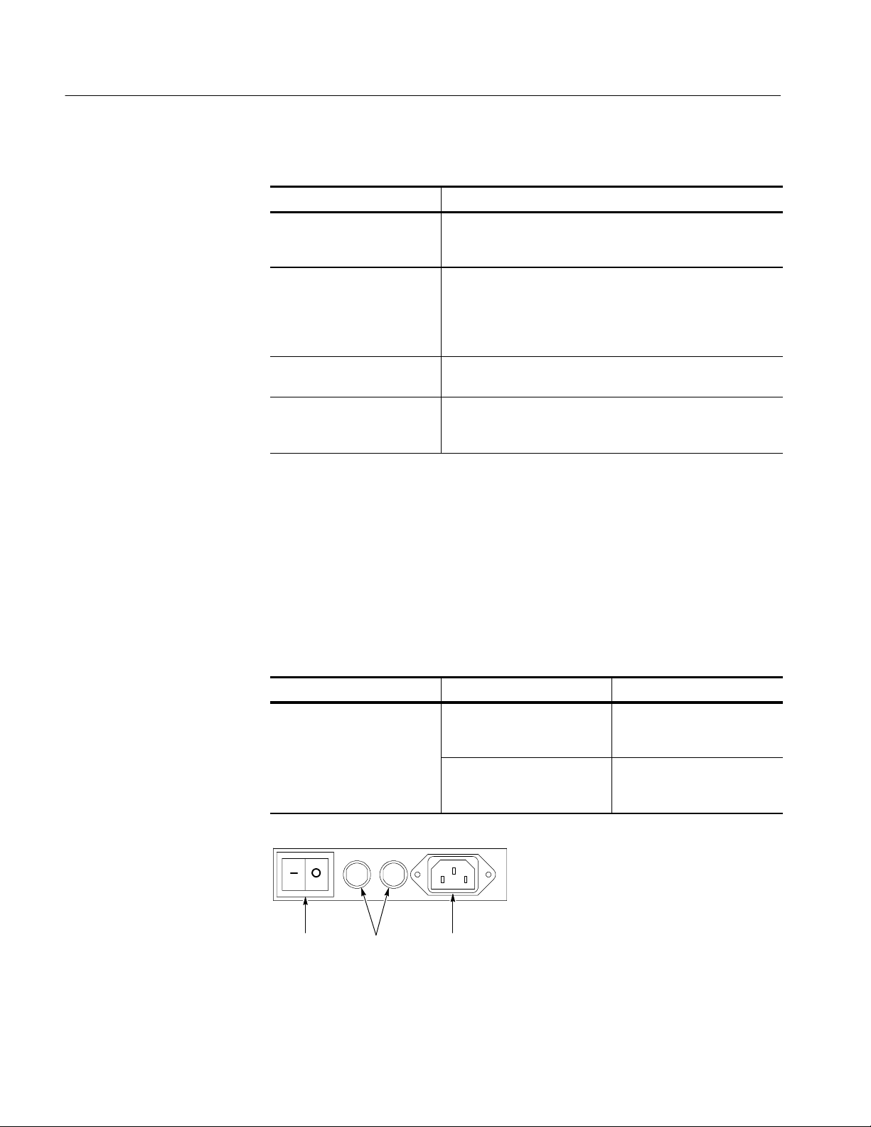
1. Either one of the following fuse sizes can be used. Each size requires a
different fuse cap. Both fuses must be the same type. See Table 1--2 and
Figure 1--2.
Table 1- 2: Line fuses
Line voltage Description Part number
100 V to 250 V operation UL198G and CSA C22.2, No.
59, fast acting: 8 A, 250 V
IEC127, sheet 1, fast acting
“F”, high breaking capacity:
6.3 A, 250 V
Tektronix 159-0046-00
Bussman ABC-8
Littelfuse 314008
Tektronix 159-0381-00
Bussman GDA-6.3
Littelfuse 21606.3
1- 8
Fuses AC powerPower switch
Figure 1- 2: Line fuse and power cord connector locations, rear panel
TDS6000 Series User Manual
Installation
CAUTION. To prevent damage to the instrument, connect the keyboard, mouse,
and other accessories before applying power to the product.
2. Connect the power cord.
3. If you have an external monitor, connect the monitor to the oscilloscope (see
page 1--14), connect the power cord, and power on the monitor.
4. Turn the Power switch on at the rear panel. (See Figure 1--2 on page 1--8 for
switch location.)
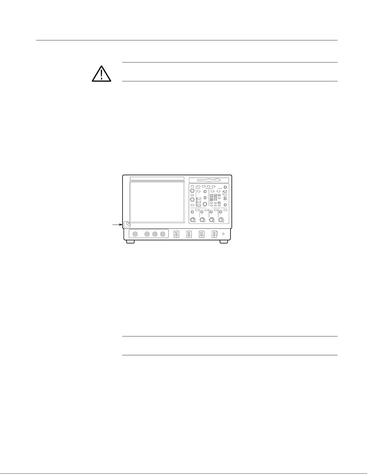
5. If the oscilloscope does not power up, push the On/Standby switch to power
on the oscilloscope (see Figure 1--3 for the switch location).
On/Standby
Switch
Figure 1- 3: On/Standby switch location
Powering Off the Oscilloscope
When you push the front-panel On/Standby switch, the oscilloscope starts a
shutdown process (including a Windows shutdown) to preserve settings and then
power off. Avoid using the rear-panel power switch or disconnecting the line
cord to power off the oscilloscope.
NOTE. If you do not use the On/Standby switch to power off the oscilloscope, the
oscilloscope will be in the factory Default Setup when powered on the next time.
To completely remove power to the oscilloscope, perform the shutdown just
described, and then set the power switch on the rear panel to off.
TDS6000 Series User Manual
1- 9

Installation
Creating an Emergency Startup Disk
Now that you have completed the basic installation process, you should create an
emergency startup disk that you can use to restart your oscilloscope in case of a
major hardware or software failure. You should create this disk, and then store it
in a safe place.
CAUTION. Create this disk and store it in a safe place. It may allow you to
recover your Windows 98 installation without rebuilding the entire oscilloscope
hard disk.
The emergency startup disk contains basic files to restart your oscilloscope. It
also contains files to check and format the hard disk.
Follow these steps to create the emergency startup disk:
1. Minimize the oscilloscope application by selecting Minimize in the File
menu.
Backing Up User Files
2. Click the Windows Start button, point to Settings, and click Control Panel.
3. In the Control Panel window, double-click Add/Remove Programs.
4. Click the tab for the Startup Disk page.
5. Insert a floppy disk into the disk drive and follow the on-screen instructions
to create the startup disk.
You should always back up your user files on a regular basis. Use the Back Up
tool to back up files stored on the hard disk. The Back Up tool is located in the
System Tools folder in the Accessories folder.
1. If the Windows backup program is not installed on your oscilloscope,
perform the following steps:
H Minimize the oscilloscope application by selecting Minimize in the File
menu.
H Click the Windows Start button, Settings, and then Control Panel.
H Double click Add/Remove Programs to display the dialog box.
1- 10
H Click the Windows Setup tab.
H Under Components, double click System Tools.
H Select the Backup check box and then click OK.
TDS6000 Series User Manual
 Loading...