

Page 1

Instructions
TDS5BUP Option 18
TDS5000B Series
Display Touch Screen Upgrade Kit
075-0813-03
Warning
The servicing instructions are for use by qualified
personnel only. To avoid personal injury, do not
perform any servicing unless you are qualified to
do so. Refer to all safety summaries prior to
performing service.
www.tektronix.com
*P075081303*
075081303
Page 2

Copyright © Tektronix. All rights reserved. Licensed software products are owned by Tektronix or its subsidiaries or
suppliers, and are protected by national copyright laws and interna tional treaty provisions.
Tektronix products are covered by U.S. and foreign patents, issued and pending. Information in this publication supercedes
that in all previously published material. Specifications and price change privileges reserved.
TEKTRONIX and TEK are registe red trademarks of Tektronix, Inc.
Contacting Tektronix
Tektronix, Inc.
14200 SW Karl Braun Drive
P.O. Box 500
Beaverton, OR 97077
USA
For product information, sales, service, and technical support:
H In North America, call 1-800-833-9200.
H Worldwide, visit www.tektronix.com to find contacts in your area.
Page 3

Service Safety Summary
Only qualified personnel should perform service procedures. Read this Service
Safety Summary and the General Safety Summary in the product service manual
or the instruction manual.
Do Not Service Alone. Do not perform internal service or adjustments of this
product unless another person capable of rendering first aid and resuscitation is
present.
Disconnect Power. To avoid electric shock, switch off the instrument power, then
disconnect the power cord from the mains power.
Use Care When Servicing With Power On. Dangerous voltages or currents may
exist in this product. Disconnect power and disconnect test leads before
removing protective panels, soldering, or replacing components.
To avoid electric shock, do not touch exposed connections.
Display Touch Screen Upgrade Kit
i
Page 4

Service Safety Summary
ii
Display Touch Screen Upgrade Kit
Page 5
Kit Description
Products
Kit Parts List
The following kit instructions describe the installation of the touch screen
upgrade (Option 18) into your TDS5000B Series oscilloscope. This upgrade
allows you to operate the oscilloscope using the touch screen.
This upgrade kit includes procedures for adjusting the gamma settings to ensure
an optimum display with the new LCD. You also need to run the touch screen
software (included on the CD with the kit), to ensure an optimum display with
the new LCD. Instructions for running the touch screen software are included in
the CD booklet.
This kit implements the changes in ECRs 31268 and 32811.
TDS5000B Series AllSerialNumbers
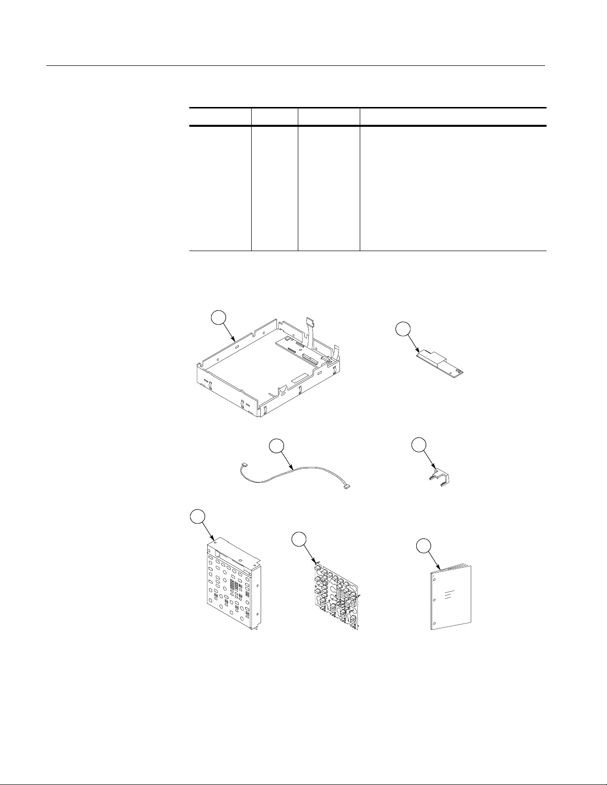
Figure 1 Quantity Part number Description
1-1 1ea 650-4553-XX* Touch screen display assembly: TDS5000B
Series, includes the following parts:
1ea 119-6845-XX Touch screen display
1ea 259-0155-XX Flex circuit: switch
2ea 348-1701-XX Gasket: Display/touch panel, w/adhesive on one
side, 9.4w X 7.1h X 0.062 thick, back
2ea 348-1700-XX Gasket: Display/touch panel, w/adhesive on both
sides, 9.4w X 7.1h X 0.062 thick, front
1ea 407-4844-XX Bracket: Touch panel, 0.050 aluminum, front
1ea 407-4845-XX Bracket: Touch panel, 0.050 aluminum, back
5ea 131-6417-XX Contact, electrical: Grounding, 0.600 l X 0.250 w
X 0.220 d, nickel plate
1ea 671-6299-XX Circuit bd: Display adapter, w/hardware
TDS5000B Series
1-2 1ea 119-6806-XX Circuit bd: Inverter, w/hardware
1-3 1 ea 174-4794-XX Cable assy; Display Adapter to Inverter, Safety
controlled
1-4 1 ea 343-1676-XX Clamp: cable restraint, gray, PC/ABS
1-5 1ea 333-4481-XX Front subpanel: 2 channel, with bezel, labels
Display Touch Screen Upgrade Kit
1
Page 6
Kit Description
Figure 1 DescriptionPart numberQuantity
1-5 1ea 333-4478-XX Front subpanel: 4 channel, with bezel, labels (for
instruments without floppy disk drive)
1ea 333-4411-XX Front subpanel: 4 channel, with bezel, labels
1-6 1 ea 260-2758-XX Switch: Keypad buttons, 2 channel
1-6 1 ea 260-2757-XX Switch: Keypad buttons, 4 channel
1-7 1 ea 075-0813-XX Kit Instructions: Display With T ouch Screen
Upgrade Kit, TDS5000B Series
Not shown 1ea 020-2989-XX**Touch Screen Switcher tool CD
* - Not Saleable
** The software installation procedure is provided in the CD booklet (071- 2207- XX).
1
2
3
5
6
Figure 1: Display touch screen upgrade kit parts
4
7
2
Display Touch Screen Upgrade Kit
Page 7

Installation Instructions
This section contains all procedures needed to install the touch screen display
into the TDS5000B Series instruments.
These instructions are for qualified service personnel who are familiar with
servicing the product. If you need further details for disassembling or reassembling the product, refer to the appropriate product manual. Contact your nearest
Tektronix Service Center or Tektronix Factory Service for installation assistance.
Gamma setting procedures are on page 15.
Touch Screen Switcher Tool instructions are in the CD booklet.
Minimum Tool and Equipment List
Most modules in the TDS5000B Digital Oscilloscope can be removed with a
screwdriver handle mounted with a size T-15, Torx-driver tip. Review Table 1 for
a complete list of tools to perform this upgrade. All tools are standard tools that
are readily available.
Table 1: Tools required for module removal
Item
number
1 Screwdriver handle Accepts Torx-driver bits 620-440
2 T-15 Torx-tip Used for removing most oscilloscope
3
4 #0 Phillips screwdriver Screwdriver for removing small
5 Angle-Tip Tweezers Used to remove Front-Panel knobs Standard tool
Name Description
screws. Torx-driver bit for T-15 size
screw heads
1
/
inch flat-bladed screw-
8
driver
Screwdriver for unlocking cable
connectors
Phillips screws, CD, floppy & hard
drive
General Tool
number
640-247
Standard tool
Standard tool
Display Touch Screen Upgrade Kit
3
Page 8

Installation Instructions
Preparation
WARNING. Before doing this or any other procedure in this manual, read the
Safety Summary found at the beginning of this manual.
This subsection contains the following items:
H The preparatory information you need to properly do the procedures that
follow.
H Procedures for removal and reinstallation of the necessary electrical and
mechanical modules.
WARNING. Before doing any procedure in this subsection, disconnect the power
cord from the line voltage source. Failure to do so could cause s erious injury or
death.
Procedures for External Modules
The following procedures are found here and are listed i n order presented.
H Line cord removal
H Trim (Front Panel) removal
H Display assembly removal
H Front Panel assembly removal
Line Cord and Trim
1. Pull the line cord away from the AC power connector.
2. Remove the Front-Panel cover, if necessary.
3. Remove the F ront-Panel trim:
a. To prevent the power button from falling out of the Front-Panel trim,
place a piece of tape over the button.
b. Remove the three T-15 Torx-drive screws that secure the Front-Panel
trim to the oscilloscope. See Figure 2 on page 5.
c. Grasp the trim ring by the top edge and pull toward you to detach the
three plastic snaps. (Alternatively, you can use a flat-bladed solder aid or
other small prying tool to help you detach the snaps.)
4
Display Touch Screen Upgrade Kit
Page 9

Installation Instructions
d. Grasp the trim ring by the side edges and slide it back and forth to
release the snap in the middle of the trim ring. The snap is at the bottom
“T” of the Front Panel above the channel 1 and 2 BNC connectors.
e. Pull off the trim ring. As you do so, take care not to lose the 3 PEM
inserts in the bottom of the trim ring.
f. Remove the Acquisition trim.
Standard Front
Panel trim
Front-Panel
cover
Figure 2: Trim removal
Display Assembly
Removal
Acquisition trim
PEM insert (3)
T-15 Torx-drive
screw (3)
1. Locate t he Display assembly. See Figure 3 on page 6.
2. Orient the oscilloscope: Set the oscilloscope on the work surface with the
Front Panel facing you.
3. Remove the Display assembly. See Figure 3.
Display Touch Screen Upgrade Kit
a. Remove the four T-15 Torx-screws that secure the display assembly to
the chassis.
5
Page 10

Installation Instructions
b. Grasp the display assembly at the finger reliefs (located at the top-right
and bottom-left corners of the display assembly), and pull forward far
enough to allow access to the flex cable connector.
c. Disconnect the J5 flex cable from the display assembly. Remove the
display module assembly from the oscilloscope.
T-15
Torx-screw (4)
J5 Flex cable
Finger relief
Finger relief
Display
assembly
Finger reliefFinger relief
Figure 3: Display assembly removal
4. Remove and disconnect the following from the old display assembly:
a. Disconnect cables J1, J4, and J7 from the Display Adapter circuit board.
See Figure 4 on page 7.
b. Disconnect the LCD light connector (S) from the Inverter circuit board.
c. Disconnect the cable that connects between the Display Adapter (J6) to
Inverter (CN1) circuit boards.
d. Remove the two number 0 Phillips screws that secure the Inverter circuit
board to the display assembly. S ave the Inverter board and Phillips
screws for later reassembly onto the new display assembly.
5. Install the old LCD assembly to the new display assembly, using the four
T-15 Torx-drive screws from the old display assembly.
6
Display Touch Screen Upgrade Kit
Page 11

Installation Instructions
J1
J6
J4
Figure 4: Remove Inverter circuit board
Cable
CN1
J7
S
LCD Light connector
Remove
screws (2)
Inverter board
Display Touch Screen Upgrade Kit
7
Page 12

Installation Instructions
CAUTION. To prevent damage to the touch screen from scratches or cuts, make
sure you take care not to contact the screen surface w ith any sharp tools.
a. Separate the display assembly by carefully prying the (outer) touch
screen panel assembly from the (inner) LCD assembly. Insert a
flat-bladed screwdriver in the access notches to push out on the Touch
panel assembly. See Figure 5.
b. Remove the four T-15 Torx-drive screws that secure the old LCD to the
old LCD assembly. See Figure 6 for T-15 screw locations.
c. Install the old LCD into the new LCD assembly using the T-15 screws
removed from the old LCD assembly.
LCD assembly
LCD module
Figure 5: Remove/install the LCD assembly and touch screen panel
Touch screen
panel
Access taps
Access notches
8
Display Touch Screen Upgrade Kit
Page 13

Old LCD
Installation Instructions
T-15 Torx-drive
screws (4)
Display light connector
New LCD assembly
Figure 6: Install the old display to the new rear bracket assembly
6. Install the new LCD assembly and touch screen panel by sliding them
together until tabs snap into the notches. See Figure 6.
7. Install the new Inverter circuit board into the new LCD assembly using the
two number 0 Phillips screws removed from the old display assembly.
Display Touch Screen Upgrade Kit
9
Page 14

Installation Instructions
8. Connect the new cable between the (CN1) and (J6) connectors on the
Inverter and Display Adapter circuit boards. See Figure 7.
9. Connect the LCD light connector (S) to the Inverter circuit board.
NOTE. The LCD and Inverter/Display connector housings have contacts visible
on one side; make s ure this side is facing up t oward the installer when you
connect the cable to both circuit boards.
Screws (2)
Display light cable
connector
New cable
New Inverter
board
CN1
Figure 7: Install the Inverter circuit board
Power flex circuit
J6
J4
J7
10
Display Touch Screen Upgrade Kit
Page 15

Installation Instructions
Touch screen
cable
J4
J1
Slide the clip
over connector
Figure 8: Cable clamp installation detail
Power flex circuit
J7
10. Connect the display cable to J4 on the Display Adapter circuit board. Slide
the cable clamp (provided in this kit) over the cable and under the Display
Adapter circuit board to secure the cable to the connector.
SeeFigure8.
11. Connect the touch screen cable to the J1 connector on the Display Adapter
circuit board.
12. Do in reverse steps 1 through 3 on page 5, to reinstall the Display assembly
into the instrument.
Display Touch Screen Upgrade Kit
11
Page 16

Installation Instructions
Front-Panel Assembly
The following procedure replaces the front subpanel and keypad with the new
touch screen assembly:
1. Set the oscilloscope bottom side down on the work surface and face the
Front Panel toward you. See Figure 9 on page 13.
2. Remove the six T-15 Torx-screws that secure the Front-Panel assembly to
the front chassis.
3. Grasp the top of Front-Panel assembly and pull it forward to allow access to
the ribbon-cable connector on the Front-Panel board.
CAUTION. To prevent damage to the touch screen from scratches or cuts, make
sure you take care not to contact the screen surface w ith any sharp tools.
1
4. Use the
@8inch flat-bladed screwdriver to carefully lift the J1 cable connector
lock up to disconnect the J1 flex cable from the display module assembly.
See Figure 10 on page 13. Note the pin 1 index mark on the connector and
the black stripe on the cable for later reassembly.
5. Pull the Front-Panel assembly forward and remove it from the oscilloscope.
12
Display Touch Screen Upgrade Kit
Page 17

Installation Instructions
T-15
Torx-screw (4)
Chassis
slot (2)
Front-Panel
Front-Panel square
opening (2)
Torx-screw (6)
Floppy disk
support tab
(2)
assembly
T-15
Figure 9: Front-Panel assembly removal
Black stripe
toward connector
J1 ribbon cable
Figure 10: J1 flex cable connector removal
Display Touch Screen Upgrade Kit
Screwdriver
13
Page 18

Installation Instructions
Front-Panel Board
Front-Panel Keypad
Remove the Front-Panel board by doing the following steps. See Figure 11.
1. Remove the eight T-15 Torx-screws that secure the Front-Panel board to the
front subpanel assembly.
2. Pry the board up off the alignment studs: Place a flat-bladed screwdriver in
the pry-point access holes to pry the board up from the assembly.
3. Remove the board from the assembly. Set the board aside for later reassembly. Discard the old front subpanel.
Remove the Front-Panel keypad by doing the following steps. See Figure 11.
1. Pull on each of the keypad support guides to separate the keypad from the
board. Use a pair of tweezers or equivalent tool to pull the twelve keypad
support guides.
2. Remove the keypad from the Front-Panel board. Discard the keypad.
Front-Panel board
Keypad support
guide (12)
Keypad
T-15
Torx-screw (8)
Alignment
stud
Pry point
access hole
Pry point access hole
Figure 11: Front subpanel board and keypad removal
14
Display Touch Screen Upgrade Kit
Page 19

Installation Instructions
CAUTION. When removing or installing the keypad, make sure you do not touch
the switch contacts with your fingers. The oils in your fingers will degrade or
damage the switch contacts. To help prevent damage to the keypad use cotton
gloves when removing or installing the keyboard pad.
3. Install the new keypad, old Front-Panel board, new front subpanel, and then
install the Front-Panel assembly back into the instrument. Do in reverse
step 2 on page 14 through step 1 on page 12. See the following instructions:
a. Make sure the keypad is aligned properly on t he Front-Panel board.
b. Make sure the ribbon cable is routed without being pinched between the
chassis and Front-Panel when installing the Front-Panel into the chassis.
c. Insert the two floppy disk support tabs into the Front Panel square
openings. Both left Front-Panel tabs must go into the chassis slots.
See Figure 9 on page 13.
4. Reinstall the Front-Panel trim, line fuse, and line cord. Do in reverse steps 1
through3onpage4.
Gamma Settings
Use the following procedure to optimize the display appearance. Try both
settings (steps 8 and 12 on page 18), to determine what display looks best to you.
1. Right click on the desktop.
2. Click the Properties menu.
Display Touch Screen Upgrade Kit
15
Page 20

Installation Instructions
3. Click the Settings tab. See Figure 12.
Figure 12: Settings tab
4. Click the Advanced button. See Figure 13.
16
Figure 13: Advanced button
Display Touch Screen Upgrade Kit
Page 21

5. Click the Color tab. See Figure 14.
Installation Instructions
Figure 14: Color tab
Display Touch Screen Upgrade Kit
17
Page 22

Installation Instructions
6. Select the Desktop graphics and Video buttons. See Figure 15.
7. In the Color menu select All.
Touch Screen Set Up
Figure 15: Brightness and button settings
8. Slide the Brightness bar to --35.
9. Click OK.
10. ClickOKontheDisplaymenu.
11. Go to the Scope display to verify how the display looks.
12. Repeat steps 1 through 11, except slide the brightness bar to --40 in step 8.
13. Set the gamma setting that looks best to you; --35 or --40.
For the touch screen set-up instructions, refer to the CD booklet that came with
your Touch Screen Switcher Tool CD.
g End of document g
18
Display Touch Screen Upgrade Kit
 Loading...