

Page 1

xx
TDS5000B Series
ZZZ
Digital Phosphor Oscilloscope
Read This First
www.tektronix.com
P061433105*
*
061-4331-05
Page 2

Copyright © Tektronix. All rights reserved. Licensed software products are owned by Tektronix or its subsidiaries
or suppliers, and are protected by national copyright laws and international treaty provisions.
Tektronix products are covered by U.S. and foreign patents, issued and pending. Information in this publication
supersedes that in all previously published material. Specifications and price change privileges reserved.
TEKTRONIX and TEK are registered trademarks of Tektronix, Inc.
Contacting Tektronix
Tektronix, Inc.
14200 SW Karl Braun Drive
P.O. Box 5 0 0
Beaverto
USA
For product information, sales, service, and technical support:
n, OR 97077
In North America, call 1-800-833-9200.
Worl dwid e, visi t www.tektronix.com to find contacts in your area.
Page 3

Table of Contents
General Safety Summary .......................................................................................... 1
Compliance Information........................................................................................... 2
EMC Compliance................................... ................................ ........................... 2
Safety Comp
Environmental Considerations .......... ................................ .................................. ... 6
Preface ............................................................................................................... 7
Quick Start User Manual Information............. ................................ ............................... 8
Getting Started .... . ..... . ..... . ..... . ..... . ..... . ..... . ..... . ..... . ... . . ..... . ..... . ..... . ..... . ..... . ..... . ... 8
Operating Requirements ... ................................ ................................ ................... 8
Powerin
Powering Off the Instrument ............ ................................ ................................ .... 10
Removing the Power ......................................................................................... 11
Using Your Instrument ......................... ................................ .............................. 11
Standard Accessories......................................................................................... 11
Service Manual Information...................................................................................... 12
ons............................... .................................. ................................ ........ 12
Opti
Side and Rear Panels ........... ................................ ................................ .............. 12
Cleaning ....................................................................................................... 14
PC Interface Board and Motherboard Cable Connections ............................................... 15
039-0185-xx Service Information......................................... ................................ .. 17
Replaceable Parts ............................................................................................. 28
ecification and Performance Verification .................................................................... 31
Sp
liance............................................................................................. 4
g On the Instrument................................................................................. 10
TDS5000B Read This First i
Page 4

Table of Contents
ii TDS5000B Read This First
Page 5

General Safety Summary
Review the following safety precautions to avoid injury and prevent damage to
this product or any products connected to it.
To avoid potential hazards, use this product only as specified.
To Avoid Fire or Personal
Injury
Use Proper Power Cord. Use only the power cord specified for this product and
certified for the country of use.
Connect and Disconnect Properly. Do not connect or disconnect probes or test
leads while they are connected to a voltage source.
Ground the Product. This product is grounded through the grounding conductor
of the power cord. To avoid electric shock, the grounding conductor must be
connected to earth ground. Before making connections to the input or output
terminals of the product, ensure that the product is properly grounded.
Observe All Terminal Ratings. To avoid fire or shock hazard, observe a ll ratings
and markings on the product. Consult the product manual for further ratings
information before making connections to the product.
The inputs are not rated for connection to mains or Category II, III, or IV circuits.
Connect the probe reference lead to earth ground only.
Do Not Operate Without Covers. Do not operate this product with covers or
panels removed.
Avoid Exposed Circuitry. Do not touch exposed connections and components
when power is present.
Do Not Operate With Suspected Failures. If you suspect that there is damage to
this product, have it inspected by qualified service personnel.
Do Not Operate in Wet/Damp Conditions.
Do Not Operate in an Explosive Atmosphere.
Keep Product Surfaces Clean and Dry.
Provide Proper Ventilation. Refer to the manual’s installation instructions for
details on installing the product so it has proper ventilation.
Terms in this Manual
TDS5000B Read This First 1
These terms may appear in this manual:
WAR NI NG . Warning statements identify conditions or practices that could result
in injury or loss of life.
Page 6
Compliance Information
CAUTION. Caution statements identify conditions or practices that could result in
damage to this
product or other property.
Symbols and Terms on the
Product
These terms may appear on the product:
DANGER indicates an injury hazard immediately accessible as you read
the marking.
WARNING indicates an injury hazard not immediately accessible as you
read the marking.
CAUTION indicates a hazard to property including the product.
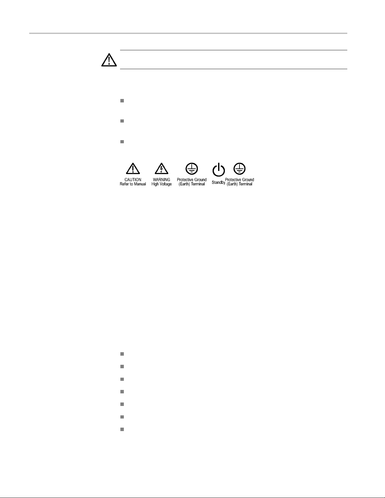
The following symbol(s) may appear on the product:
Compliance Information
This section lists the EMC (electromagnetic compliance), safety, and
environmental standards with which the instrument complies. This EMC section
replaces the Certifications and Compliances section in Table 1–11, of the
TDS5000B Series Technical Reference manual (071-1420-xx).
EMC Compliance
EC Declaration of
Conformity – EMC
Meets intent of Directive 2004/108/EC for Electromagnetic Compatibility.
Compliance was demonstrated to the following specifications as listed in the
Official Journal of the European Com
EN 61326-1:2006, EN 61326-2-1:2006. EMC requirements for electrical equipment
for measurement, control, and laboratory use.
CISPR 11:2003. Radiated and conducted emissions, Group 1, Class A
IEC 61000-4-2:2001. Electrostatic discharge immunity
IEC 61000-4-3:2002. RF electromagnetic field immunity
IEC 61000-4-4:2004. Electrical fast transient/burst immunity
IEC 61000-4-5:2001. Power line surge immunity
IEC 61000-4-6:2003. Conducted RF immunity
IEC 61000-4-11:2004. Voltage dips and interruptions immunity
munities:
1234
5
5
6
2 TDS5000B Read This First
Page 7

Compliance Information
EN 61000-3-2:2
006. AC power line harmonic emissions
EN 61000-3-3:1995. Voltage changes, fluctuations, and flicker
European Contact.
Tektronix UK, Ltd.
West ern Pe n
insula
West ern Road
Bracknell, RG12 1RF
United Kingdom
1
This product is intended for use in nonresidential areas only. Use in residential areas may cause electromagnetic
interference.
2
Emissions which exceed the levels required by this standard may occur when this equipment is connected to a
test object.
3
To ensure compliance with the EMC standards listed here, high quality shielded interface cables should be used.
4
Instrument rebooting may be experienced where the EUT takes longer than 10 seconds to recover from IEC
61000-4-11 transient immunity test.
5
Under these conditions, the specifications are amended as follows: 1 mV/division to 1 V/division: < 0.2 division
waveform displacement or < 0.4 division increase in peak -to peak noise for (IEC 61000-4-3 and IEC 61000-4-6
tests)
6
Performance Criterion C applied at the 70%/25 cycle Voltage-Dip and the 0%/250 cycle Voltage-Interruption test
levels (IEC 61000-4-11).
Australia / New Zealand
Declaration of
Conform
ity–EMC
Complies with the EMC provision of the Radiocommunications Act per the
following standard, in accordance with ACMA:
CISPR 11:2003. Radiated and Conducted Emissions, Group 1, Class A, in
accordance with EN 61326-1:2006 and EN 61326-2-1:2006.
TDS5000B Read This First 3
Page 8

Compliance Information
Safety Compli
ance
EC Declaration of
Conformity – Low Voltage
U.S. Natio
nally Recognized
Testing Laboratory Listing
Canadian Certification
Additional Compliances
Equipment Type
Compliance was demonstrated to the following specification as listed in the
Official Journal of the European Communities:
Low Voltage Directive 2006/95/EC.
EN 61010-1: 2001. Safety requirements for electrical equipment for
measurement control and laboratory use.
UL 61010B-1. Standard for electrical measuring and test equipment.
CAN/CSA-C22.2 No. 61010.1-97. Safety requirements for electrical
equipment for measurement, control, and laboratory use. Part 1.
IEC 61010-1: 2001. Safety requirements for electrical equipment for
measurement, control, and laboratory use.
nd measuring equipment.
Test a
Safety Class
Pollution Degree
Description
Pollution Degree
Class 1 – grounded product.
A measure of the contaminants that could occur in the environment around
and within a product. Typically the internal environment inside a product is
considered to be the same as the external. Products should be used only in the
environment for which they are rated.
Pollution Degree 2. Normally only dry, nonconductive pollution occurs.
Occasionally a temporary conductivity that is caused by condensation must
expected. This location is a typical office/home environment. Temporary
be
condensation occurs only when the product is out of service.
Pollution Degree 2 (as defined in IEC 61010-1). Note: Rated for indoor use only.
4 TDS5000B Read This First
Page 9

Compliance Information
Installation (Overvoltage)
Category Descriptions
Overvoltage Category
Terminals on th
designations. The installation categories are:
Measurement C
low-voltage installation.
Measuremen
installation.
Measuremen
connected to the low-voltage installation.
Measureme
directly connected to MAINS.
Overvoltage Category II (as defined in IEC 61010-1)
is product may have different installation (overvoltage) category
ategory IV. For measurements performed at the source of
t Category III. For measurements performed in the building
t Category II. For m easurements performed on circuits directly
nt Category I. For measurements performed on circuits not
TDS5000B Read This First 5
Page 10

Compliance Information
Environmenta
Product End-of-Life
l Considerations
This section provides information about the environmental impact of the product.
Observe the following guidelines when recycling an instrument or component:
Handling
Equipment Recycling. Production of this equipment required the extraction and
use of natural resources. The equipment may contain substances that could be
harmful to
end of life. In order to avoid release of such substances into the environment and
to reduce the use of natural resources, w e encourage you to recycle this product
in an appropriate system that will ensure that most of the materials are reused or
recycled appropriately.
Mercur
mercury. Disposal may be regulated due to environmental considerations. Please
contact your local authorities or, within the U nited States, refer to the E-cycling
Central Web page (www.eiae.org) for disposal or recycling information.
yNotification. This product uses an LCD backlight lamp that contains
the environment or human health if improperly handled at the product’s
This sym
Union requirements according to Directives 2002/96/EC and 2006/66/EC
on waste electrical and electronic equipment (WEEE) and batteries. For
informa
Tektronix Web site (www.tektronix.com).
bol indicates that this product complies with the applicable European
tion about recycling options, check the Support/Service section of the
Restriction of Hazardous
Substances
Perchlorate Materials. This product contains one or more type CR lithium
eries. According to the state of California, CR lithium batteries are
batt
classified as perchlorate materials and require special handling. See
www.dtsc.ca.gov/hazardouswaste/perchlorate for additional information.
is product has been classified as Monitoring and Control equipment, and is
Th
outside the scope of the 2002/95/EC RoHS Directive.
6 TDS5000B Read This First
Page 11

Preface
Preface
The followin
and the TDS5000B Series Service manual.
g information affects the TDS5000B Series Quick Start User manual
TDS5000B Read This First 7
Page 12

Quick Start User Manual Information
Quick Start Us
er Manual Information
Getting Started
Use the foll
instrument quick start user manual documentation.
Operating Requirements
Place the bottom fee t of the instrument on a cart or bench and observe the
following clearance requirements:
owing information to replace or clarify information contained in your
Top, Rear, Front, and Right Side: 0 in (0 mm)
Left Sid
Bottom: 0.75 in (19 mm) minimum or 0 in (0 mm) standing on feet, flip
stand d
e: 3 in (76 mm)
own
TION. To ensure proper cooling, keep the bottom and sides of the instrument
CAU
clear of obstructions.
8 TDS5000B Read This First
Page 13

Quick Start User Manual Information
Environmental
Characteristic Description
Humidity, ope
Altitude, operating
Temperature, ambient operating
Maximum voltage
1MΩ input impedance 150 VRMS CAT I, and ≤400 peak
50 Ω input impedance <1 Vrms for settings below 100 mV/div
Requirements
rating
20% to 80% relative humidity with a maximum
wet bulb temperature of +29 °C (+84.2 °F) at
or below +45 °
Upper limit derated to 30% relative humidity
at +45 °C (+113 °F)
9,842 ft. (3,000 m)
+5 °C to +45 °C (+41 °F to +113 °F)
For steady-state sinusoidal waveforms,
derate at 2
9VRMSat≥3MHz
<5 Vrms for 100 mV/div settings and above
C (+113 °F) noncondensing.
0 dB/decade above 200 kHz to
TDS5000B Read This First 9
Page 14
Quick Start User Manual Information
Powering On th
e Instrument
Power Supply Requirements
Source volta
100-240 V
115 V
RMS
WARNING. To avoid fire or shock hazard that could result in injury or loss of life,
observe al
further ratings information before making connections to the product.
ge and frequency
±10%, 47-63 Hz, or
RMS
±10%, 360-440 Hz
Power consum
<220 watts
ption
l ratings and markings on the product. Consult the product manual for
Powering Off the Instrument
10 TDS5000B Read This First
Page 15
Removing the Power
Using Your Instrument
Quick Start User Manual Information
Documentation for your instrument is found by selecting Help >
Document
ation....
Standard Accessories
Before using your instrument, read the following information in the quick start
user man
The standard accessories list in the TDS5000B Series Quick Start User manual
(071-1355-XX) has been upgraded to include the following discs:
ual:
Safety Summary
Creating an Emergency Startup Disk
Getting Acquainted with Your Instrument
TDS5000B Series Operating System Restore disc (SN B040000 and above)
063-4160-xx.
TDS5000B Series Operating System Restore disc (SN B030000 to B039999)
063-3985-xx.
TDS5000B Series Operating System Restore disc (SN B020000 to SN
B029999) 063-3759-xx
TDS5000B Series Operating System Restore disc (SN B010100 to SN
B019999) 063-3693-xx
NOTE. Only serial numbers below B060100 include a fl oppy disc.
TDS5000B Read This First 11
Page 16
Service Manual Information
Service Manua
Options
Side and R
ear Panels
l Information
Use the follo
your TDS5000B Series Digital Phosphor Oscilloscopes (071-1362-XX) service
manual. This service manual is on the Tektronix Web site.
The TDS5054B and TDS5104B instruments have been upgraded to include the
following options: Option 18 (Touch Screen) and Option 3M (16 M points record
length).
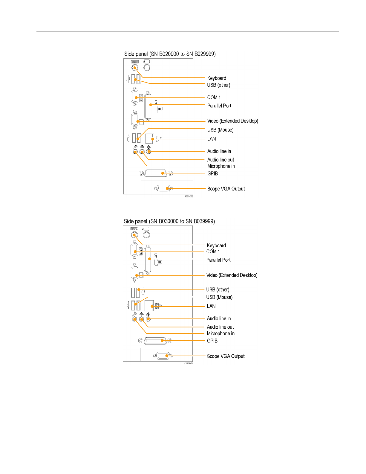
The following side-panel illustrations (in the Theory of Operation section) have
been upgraded to include the latest component locations and are for reference
only. U
(071-1355-XX) to connect your instrument.
wing information to replace or clarify information contained in
se the instructions in the TDS5000B Series Quick Start User manual
12 TDS5000B Read This First
Page 17
Service Manual Information
TDS5000B Read This First 13
Page 18

Service Manual Information
Cleaning
Exterior Cleaning
Use these procedures to clean your oscilloscope. If additional cleaning is required
have your oscilloscope serviced by qualified service personnel.
Clean the exterior surfaces of the chassis with a dry lint-free cloth or a soft-bristle
brush. If any dirt remains, use a cloth or swab dipped in a 75% isopropyl alcohol
solution. Use a swab to clean narrow spaces around controls and connectors.
Do not use abrasive compounds on any part of the chassis that may damage the
sis.
chas
Clean the On/Standby switch using a dampened cleaning towel. Do not spray or
the switch directly.
wet
CAUTION. Do not use chemical cleaning agents that might damage the plastics
used in this oscilloscope. Use only deionized water when cleaning the front-panel
buttons. Use a 75% isopropyl alcohol solution as a cleaner and rinse with
deionized water. Before using any other type of cleaner, contact your Tektronix
Service Center or representative.
Clean the flat panel display surface by gently rubbing the display with a
clean-room wipe (such as Wypall Medium Duty Wipes, #05701, available from
Kimberly-Clark Corporation).
14 TDS5000B Read This First
Page 19
Service Manual Information
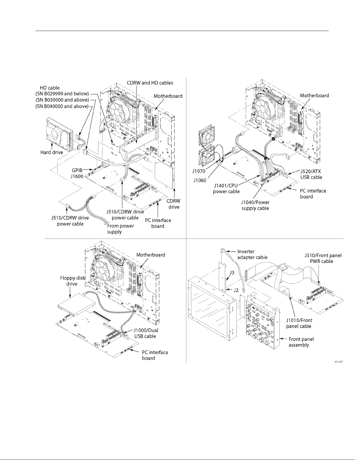
PC Interface B
oard and Motherboard Cable Connections
Replace Figures 6-17 and 6–18 in the Removal and Installation Procedures).
Figure 6-17: PC Interface board and motherboard cable connections
TDS5000B Read This First 15
Page 20
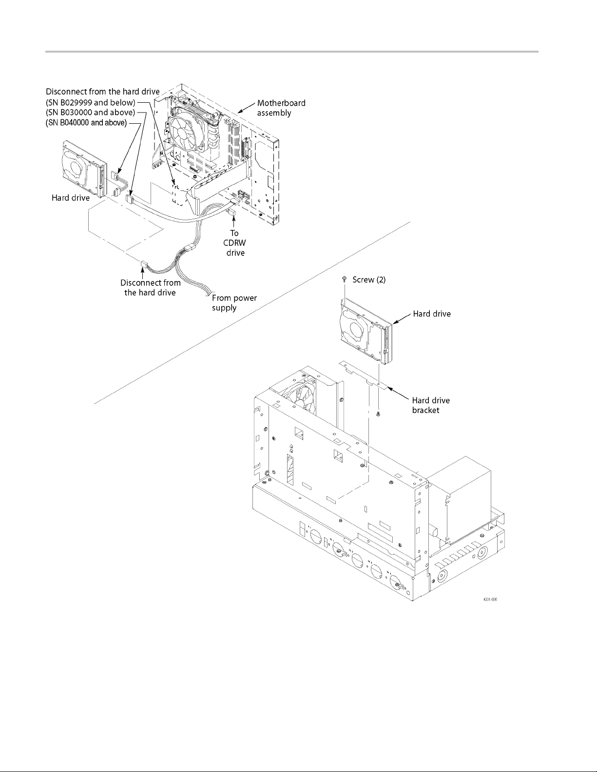
Service Manual Information
Figure 6-18: Desktop hard drive removal
16 TDS5000B Read This First
Page 21

Service Manual Information
039-0185-xx S
ervice Information
Use the following information when servicing instruments with serial numbers
B040000 and above or instruments using the 039-0185-xx Mother board. This
information
Table 1: 039-0185-xx μATX POST codes
Item no. Module
1
2 Memory Presence
3 Early Memory
4 Extend Memory DRAM
Turn Off Chipset and
CPU test
Initialization
select
is only for qualified service personnel.
Displayed POST
code Description
C0
C1
C2 OEM Specific-Board Initialization
C3
OEM Specific-Cache control cache
Processor Status (1FLAGS) Verification
Tests the following proce ssor status flags: Carry, zero, sign,
overflow.
The BIOS sets each flag and verifies.
The flags are set, then turns each flag off and verifies if it is off.
Read/Write/Verify all the CPU r egisters except SS, SP, and BP
with data pattern FF and 00.
RAM must be periodically refreshed to keep the memory from
decaying. This function ensures that the memory refresh
function is working properly.
First block memory detect
OEM Specific-Test to size on-board memory
Early chip set initialization
Memory presence test
OEM c hip set routines
Clear low 64K of memory
Test first 64K memory
OEM Specific-Turn on extended memory
Initialization
Cyrix CPU initialization
Cache initialization
TDS5000B Read This First 17
Page 22

Service Manual Information
Table 1: 039-0185-xx μATX POST codes, (cont.)
Displayed POST
Item no. Module
5
6
7
8
9
10 Unclaimed NMI B1
11
12
Special Display
Handling
Early Shadow C5 OEM specific-Early shadow enable for fast boot
Cache presence test C6
CMOS Check CF CMOS checkup
Spurious
Program Chip Set
Setup Pages
Force load Default to
chipset
Reserved 2
Early Super IO Init
Reserved 4
Blank video
Reserved 6
Init KBC
KB test 8 Test the keyboard
Reserved 9
Mouse Init A Initialize the mouse
Onboard Audio init
Reserved
Reserved D
CheckSum Check
Reserved F
Auto detect E EPROM
Reserved 11
CMOS Check
Reserved 13
Chipset Default load
Reserved 15
Clock Init
Reserved 17
Identify the CPU
code Description
C4 OEM Specific-Display/Video Switch
B0
BF
E1–EF E1- Page 1, E2 - Page 2, and so on
1
3
5
7
B
C
E
10
12
14
16 Init onboard clock generator
18
Handling so that the Switch Handling display switch errors
never occur
External cache size detection
If interrupt occurs in protected mode.
If unmasked NMI occurs, display
Press F1 to disable NMI, F2 reboot.
To program chipset from defaults values
Chipset defaults program
Early Initialize of the super IO
Reset the Video controller
Keyboard controller init
Initialize the onboard audio controller if it exits
Check the integrity of the ROM, BIOS, and message
Check the Flash type and copy flash
write/erase routines to 0F000h segments
Check CMOS circuitry and reset CMOS
Program the chipset registers with CMOS values
Check the CPU ID and init L1/L2 cache
18 TDS5000B Read This First
Page 23

Table 1: 039-0185-xx μATX POST codes, (cont.)
Displayed POST
Item no. Module
12
Reserved 19
Reserved 1A
Setup Interrupt Vector
Table
Reserved
Early PM Init 1D
Reserved 1E
Re-initial KB 1F Re-init KB
Reserved 20
HPM init 21
Reserved 22
Test CMOS Interface
and Battery Status
Reserved 24
Reserved 25
Reserved 26
KBC final Init
Reserved 28
Initialize Video Inter face
Reserved 2A
Reserved 2B
Reserved
Video memory test 2D Test video memory, write sign-on message to screen.
Reserved 2E
Reserved 2F
Reserved 30
Reserved 31
Reserved 32
PS2 Mouse setup
Reserved 34
Test DMA Controller 0
Reserved 36
Test DMA Controller 1
code Description
1B
1C
23
27
29
2C
33
35 Test DMA channel 0
37 Test DMA channel 1
Service Manual Information
Initialize first 120 interrupt vectors with SPURIOUS_INT_HDLR
and
initialize INT 00h-1Fh according to INT_TBL
First step initialize if single CPU onboard
If support HPM, HPM get initialized here
Verifies CMOS is working correctly and detects bad battery.
If failed, load CMOS defaults and load into chipset
Final Initial KBC and setup BIOS data area
Read CMOS location 14h to find out type of video in use.
Detect and Initialize Video Adapter.
Setup shadow RAM - Enable shadow according to Setup.
Setup shadow RAM - Enable shadow according to Setup.
Setup PS2 Mouse and reset KB
TDS5000B Read This First 19
Page 24

Service Manual Information
Table 1: 039-0185-xx μATX POST codes, (cont.)
Displayed POST
Item no. Module
12
Reserved 38
Test DMA Page
Registers
Reserved 3A
Reserved 3B
Test Timer Counter 2 3C Test 8254 Timer 0 Counter 2.
Reserved 3D
Test 8259-1 Mask Bits 3E
Reserved 3F
Test 8259-2 Mask Bits 40
Reserved 41
Reserved 42
Test Stuck 8259’s
Interrupt Bits
Test 8259 Interrupt
Functionality
Reserved 44
Reserved 45
Reserved 46
Set EISA Mode
Reserved 48
Size Base and Extended
Memory
Reserved 4A
Reserved 4B
Reserved
Reserved 4D
Test Base and Extended
Memory
code Description
39 Test DMA Page Registers.
43
47
49
4C
4E
Verify 8259 Channel 1 masked interrupts by alternately turning
off and on the interrupt lines.
Verify 8259 Channel 2 masked interrupts by alternately turning
off and on the interrupt lines.
Turn off interrupts then verify no interrupt mask register is on.
Force an interrupt and verify the interrupt occurred.
If EISA non-volatile memory checksum is good, execute EISA
initialization.
If not, execute ISA tests an clear EISA mode flag.
Size base memory from 256 K to 640 K and extended memory
above 1 MB.
Test base memory from 256K to 640K and extended memory
above 1 MB using various patterns.
NOTE. This test is skipped in EISA mode and can be skipped
with ESC key in ISA mode.
Reserved 4F
USB init
Reserved 51
50
Initialize USB controller
20 TDS5000B Read This First
Page 25

Table 1: 039-0185-xx μATX POST codes, (cont.)
Displayed POST
Item no. Module
12
Memory Test 52
Reserved 53
Reserved 54
CPU display
Reserved 56
PnP Init
Reserved 58
Setup Virus Protect
Reserved 5A
Awdflash Load
Reserved
Onboard I/O Init
Reserved 5E
Reserved 5F
Setup enable
Reserved 61
Reserved 62
Initialize & Install Mouse
Reserved 64
PS2 Mouse special
Reserved 66
ACPI init
Reserved 68
Setup Cache Controller
Reserved 6A
Setup Entering
Reserved
Initialize Floppy Drive &
Controller
Reserved 6E
FDD install 6F
Reserved 70
code Description
55
57
59
5B
5C
5D
60
63
65
67
69 Initialize cache controller
6B
6C
6D
Service Manual Information
Test all memory of memory above 1 MB using Virtual 8086
mode, page mode, and clear the memory
Detect CPU speed and display
CPU vendor specific version string and turn on all necessary
CPU features
Display PnP logo and PnP early init
Setup virus protect according to Setup
If required, will auto load Awdflash.exe in POST
Initializing onboard super IO
Display setup message and enable setup functions
Detect if mouse is present
initialize mouse
install interrupt vectors
Special treatment to PS2 Mouse port
ACPI s ub-system initializing
Enter setup check and auto-configuration check up
Initialize floppy disk drive controller and any drives.
Install FDD and setup BIOS data area parameters
TDS5000B Read This First 21
Page 26

Service Manual Information
Table 1: 039-0185-xx μATX POST codes, (cont.)
Displayed POST
Item no. Module
12
Reserved 71
Reserved 72
Initialize Hard Drive &
Controller
Reserved 74
Install HDD
Reserved 76
Detect & Initializ e
Serial/Parallel
Reserved 78
Reserved 79
Detect & Initialize Math
Coprocessor
Reserved 7B
HDD Check for Write
protection
Reserved 7D
Reserved 7E
POST error check
Reserved 80
Reserved 81
Security Check
Write CMOS
Pre-boot Enable 84 Enable parity checker
Initialize Option ROMs
code Description
73 Initialize hard drive controller and any drives.
75
77
7A Initialize math coprocessor
7C
7F
82
83
85
IDE device detection and install
Initialize any serial and parallel ports (also game port)
HDD check out
Check POST error and display them and ask for user
intervention
Ask password security (optional)
Write all CMOS values back to RAM and clear screen
Enable NMI, enable cache before boot.
Initialize any option ROMs present from C8000h to EFFFFh.
NOTE. When FSCAN option is enabled, ROMs initialize from
C8000h to F7FFFh.
Reserved 86
Reserved 87
Reserved 88
Reserved 89
Reserved 8A
Reserved 8B
Reserved
8C
22 TDS5000B Read This First
Page 27

Table 1: 039-0185-xx μATX POST codes, (cont.)
Displayed POST
Item no. Module
12
Quick POST Codes
13
Reserved 8D
Reserved 8E
Reserved 8F
Reserved 90
Reserved 91
Reserved 92
Boot Medium detection 93 Read and store boot partition head and
Final Init 94
Special KBC patch
Boot Attempt 96
Boot FF
Init onboard device 65
Early System setup
KBC and CMOS Init
Video Init 68
8259 Init 69
code Description
95
66
67
Service Manual Information
Final init for last micro details before boot
Set system speed for boot Setup NumLock status according to
Setup
Set low stack Boot via INT 19h.
Early Initialized the super IO
Reset Video controller
Keyboard controller init
Test the Keyboard
Initialized the mouse
Onboard audio controller initialize if exist
Check the integrity of the ROM, BIOS, and message
Check Flash type and copy flash write/erase routines to
0F000h segments
Check CMOS Circuitry and reset CMOS Program the chipset
registers with CMOS values Init onboard clock generator
Check the CPU ID and init L1/L2 cache
Initialize first 120 interrupt vectors with SPURIOUS_INT_HDLR
and initialize INT 00h-1Fh according to INT_TBL First step
initialize if single CPU onboard.
Re-init KB If support HPM, HPM get initialized here
Verifies CMOS is working correctly
detects bad battery
If failed, load CMOS defaults and load into chipset
Final Initial KBC and setup BIOS data area.
Read CMOS location 14h to find out type of video in use.
Detect and Initialize Video Adapter.
Test video memory, write sign-on message to screen.
Setup shadow RAM - Enable shadow according to Setup.
Init 8259 channel 1 and mask IRQ 9
TDS5000B Read This First 23
Page 28

Service Manual Information
Table 1: 039-0185-xx μATX POST codes, (cont.)
Displayed POST
Item no. Module
13
Memory test 6A
CPU Detect and IO init
Reserved
Reserved 6D
Reserved 6E
Reserved 6F
Setup Init
Setup Cache C ontroller
Install FDD 72
Install HDD 73 Initialize hard drive controller and any drives
Detect & Initialize Math
Coprocessor
HDD Check for Write
protection
Reserved 76
Display POST error
CMOS and Option ROM
Init
code Description
6B
6C
70
71 Initialize cache controller
74 Initialize math coprocessor
75
77
78
Quick M emory Test
Detect CPU speed and display CPU vendor specific version
string and turn on all necessary CPU features
Display PnP logo and PnP early init
Setup virus protect according to Setup.
If required, will auto load Awdflash.exe in POST
Initializing onboard super IO
Display setup message and enable setup functions
Detect if mouse is present, initialize mouse, install interrupt
vectors
Special treatment to PS2 Mouse port
ACPI sub-system initializing
Enter setup check and auto-configuration check up
Initialize floppy disk drive controller and any drives
Install FDD and setup BIOS data area parameters
IDE device detection and install Initialize any serial and parallel
ports (also game port)
HDD check out
Check POST error and display them and ask for user
intervention
Ask password security (optional)
Write all CMOS values back to RAM and clear screen
Enable parity checker
Enable NMI
Enable cache before boot.
24 TDS5000B Read This First
Page 29

Table 1: 039-0185-xx μATX POST codes, (cont.)
Displayed POST
Item no. Module
13
Reserved 79
Reserved 7A
Reserved 7B
Reserved
Boot Medium detection 7D Read and store boot partition head and cylinders values in
Final Init 7E
Special KBC patch
Boot Attempt 80
Boot FF
S4 POST Codes
14
Early Chipset Init
Cmos Check
Chipset default Prog 5C Program the chipset registers with CMO S values. Init onboard
Identify the CPU
Setup Interrupt Vector
Table
Test CMOS Interface
and Battery status
KBC final Init
Initialize Video Inter face
code Description
7C
7F
5A
5B
5D
5E
5F
60
61
Service Manual Information
Initialize any option ROMs present from C8000h to EFFFFh
NOTE. When FSCAN option is enabled, ROMs initialize from
C8000h to F7FFFh.
RAM
Final init for last micro details before boot
Set system speed for boot Setup NumLock status according to
Setup
Set low stack Boot via INT 19h
Early Initialized the super IO
Reset Video controller
Keyboard controller init
Test the Keyboard
Initialized the mouse
Check CMOS Circuitry and reset CMOS
clock generator
Check the CPU ID and init L1/L2 cache
Initialize first 120 interrupt vectors with SPURIOUS_INT_HDLR
and INT 00h-1Fh according to INT_TBL
First step initialize if single CPU Onboard
Re-init KB
If support HPM, HPM get initialized here.
Verifies CMOS is working correctly
detects bad battery. If failed, load CMOS defaults and load
into chipset
Final Initial KBC and setup BIOS data area
Read CMOS location 14h to find out type of video in use
Detect and Initialize Video Adapter
TDS5000B Read This First 25
Page 30

Service Manual Information
Table 1: 039-0185-xx μATX POST codes, (cont.)
Displayed POST
Item no. Module
14
BootBlock POST Codes
15
Video memory test 62 Test video memory, write sign-on message to screen
Setup PS2 mouse and
test DM A
Test 8259 64
Init Boot Device 65
Install Boot Devices 66
Cache Init
PM init 68 PM initialization
PM final Init and issue
SMI
Full on FF
Base memory test 1
KB init
Install interrupt vectors 12
Init Video 0D Video initializing
Init FDD 41
Boot FF Load boot sector
code Description
63
67
69
5
Setup shadow RAM - Enable shadow according to Setup
Setup PS2 Mouse and reset KB Test DMA channel 0
Test 8259 channel 1 and mask IRQ 9
Detect if mouse is present, initialize mouse, install interrupt
vectors
Special treatment to PS2 Mouse port ACPI sub-system
initializing Initialize cache controller
Enter setup check and auto-configuration check up
Initialize floppy disk drive controller and any drives
Install FDD and setup BIOS data area
Parameters Initialize hard drive
Cache init and USB init
Final init Before resume
Clear base memory area (0000:0000–9000:ffffh)
Initialized KBC
Install int. vector (0-77) and initialized 00-1fh to their proper
place
Scan floppy and media capacity for onboard super IO
26 TDS5000B Read This First
Page 31

Service Manual Information
Table 2: 039-01
Item
no. Beep code Error message Description
1 1 long, 2 short Video adapter
2 R epeating
3 1 long, 3 short No video card or bad video RAM Reseat or replace the video card.
4
5
85-xx μATX beep codes
endless loop
High frequency
beeps whil
running
Repeating
High/Low
e
error
Memory error
Overheated CPU Check the CPU fan for proper operation and
CPU Either the CPU is not seated properly or it is
Bad video adap
video adapter. Ensure that the monitor cable
is connected properly.
Check for improperly seated or missing
memory.
check the c
damaged. The problem can also be due to
excess he
settings for proper fan speed.
ter or a bad connection to the
ase for proper air flow.
at. C heck the CPU fan or BIOS
TDS5000B Read This First 27
Page 32

Service Manual Information
Replaceable Parts
External parts
Use the following information to replace or clarify parts list information in the
service manual.
Fig. &
index
number
10-1-(not
shown)
Inner Pane
Fig. &
index
number
10-2-10
es
Modul
Fig. &
index
number
10-3-5
Tektronix
part
number
101-0158-xx B030000 1
Serial no.
effective
Serial no.
discont’d Qty Name & description
ls
Tektronix
part
number
441-2226-xx B010100 B019999 1
441-2376-xx B020000 B029999 1
441-2491-xx B030000 B039999 1
441-2557-xx B040000 1
Tektronix
part
number
039-0154-xx B010100 B019999 1
039-0159-xx B020000 B029999 1
039-0173-xx B030000 B039999 1
039-0185-xx B040000 1
Serial no.
effective
lno.
Seria
effective
Serial no.
discont’d Qty Name & description
l no.
Seria
discont’d Qty Name & description
TRIM RING; FR110,PC/ABS
CHASSIS ASSY;FOR ASHLAND MOTHER BOARD,0.050 AL
W/BRACKETS & HARDWARE
CHASSIS ASSY;FOR LACROSSE MOTHER BOARD,0.050 AL
W/BRACKETS & HARDWARE
CHASSIS ASSY;FOR TAPPEN MOTHER BOARD,0.050 AL
W/BRACKETS & HARDWARE
CHASSIS ASSY;FOR ADVANTECH MOTHER BOARD,0.050 AL
W/BRACKETS & HARDWARE
MOTHER BOARD ASSY;PENTIUM 4/CELERON BD, UATX,ASHLAND
2.1,W/O PROCESSOR,D845GVAD2L
MOTHER BOARD ASSY;PENTIUM 4/CELERON BD, UATX,LA
CROSSE,W/O PROCESSOR,BLKD865GLCLK INTEL P/N,SAFETY
CONTROLLED
MOTHER BOARD ASSY;PENTIUM 4, UATX,TAPPEN
BD,GIG E, PROCESSOR LGA775,DDR2 667MHZ,TOTAL 4
GIG,BLKD945GTPLKR,SAFETY CONTROLLED
MOTHER BOARD ASSY;ADVANTECH MICROATX, LGA 775
CORE 2 DUO, DDR2, PCI-E X1, SINGLE GBE LAN; ADVANTECH
AIMB-562VG-00A1E WITH ADD2 DISABLE AND BIOS 562X126N.BIN
SAFETY CONTROLLED
28 TDS5000B Read This First
Page 33

External parts
Service Manual Information
Fig. &
index
number
10-4-1
4b 174-5639-xx B040000+ 1
-5
Tektronix
part
number
119-7524-xx 1
119-6833-xx B010100 B060099 1
Serial no.
effective
Serial no.
discont’d Qty Name & description
DISK DRIVE,HARD; 160GB, 3.5 INCH, 7200 RPM, SATA II 3.0 GB/S
INTERFACE;,SAFETY CONTROLLED
CABLE ASSY MOLEX TO SATA POWER ADAPTER
DISK DRIVE; USB FLOPPY,3.5 INCH;1.44MB,0.5 INCH,TWO
SIDED,DOUBLE DENSITY,SAFETY CONTROLLED
Table 10–4 Drives
TDS5000B Read This First 29
Page 34

Service Manual Information
Accessories
Fig. &
index
number
10-6-
Tektronix
part
number
063-3693-xx B010100 B019999 1
063-3759-xx B020000 B029999 1
063-3985-xx B030000 B039999 1
020-2969-xx B040000 1
Serial no.
effective
Serial no.
discont’d Qty Name & description
TDS5000B SERIES OPERATING SYSTEM RESTORE CD
TDS5000B SERIES OPERATING SYSTEM RESTORE CD
TDS5000B SERIES OPERATING SYSTEM RESTORE CD
TDS5000B SERIES OPERATING SYSTEM RESTORE CD KIT
30 TDS5000B Read This First
Page 35

Specification and Performance Verification
Specification
and Performance Verification
Check the TDS
Performance Verification (071-1420-XX) manual on the Tektronix Web site for
the latest updates and a complete list of instrument specifications. The Web
site address is located on the copyright page at the front of this Read This First
document.
5000B Series Digital Phosphor Oscilloscopes Specifications and
TDS5000B Read This First 31
Page 36

Service Manual
TDS5000B Series
Digital Phosphor Oscilloscopes
071-1362-02
Revision A
This document applies to firmware version 1.00
and above.
Warning
The servicing instructions are for use by qualified
personnel only. To avoid personal injury, do not
perform any servicing unless you are qualified to
do so. Refer to all safety summaries prior to
performing service.
www.tektronix.com
Page 37

Copyright © Tektronix. All rights reserved. Licensed software products are owned by Tektronix or its subsidiaries or
suppliers, and are protected by na tional copyright laws and international treaty provisions.
Tektronix products are covered by U.S. and foreign patents, issued and pending. Information in this publication supercedes
that in al l previously published material. Specifications and price change privi leges reserved.
TEKTRONIX and TEK are registered trademarks of Tektronix, Inc.
Contacting Tektronix
Tektronix, Inc.
14200 SW Karl Braun Drive
P.O. Box 500
Beaverton, OR 97077
USA
For product information, sales, service, and technical support:
H In North America, call 1-800-833-9200.
H Worldwide, visit www.tektronix.com to find contacts in your area.
Page 38

Warranty 2
Tektronix warrant s that this product will be free from defects in materials and workmanship for a period of one (1)
year from the date of shipment . If any such product proves defective during this warranty period, Tektronix, at i ts
option, either will repair the defective product without cha rge for parts and labor, or will provide a replacement in
exchange for the defective product. Parts, modules and replacement products used by Tektronix for warranty work
may be new or reconditioned to l ike new performance. All replaced parts, modules and products become the
property of Tektronix.
In order to obtain service under this warranty, Customer must notify Tektronix of the defect before the expiration
of the warranty period and make suitable arrangements for the performance of service. Customer shall be
responsible for packagi ng and shipping the defective product to the service center designated by Tektronix, with
shipping charges prepaid. Tektronix shall pay for the return of the product to Customer if the shipment is to a
location within the country in which the Tektronix service center is located. Customer shall be responsible for
paying all shippi ng charges, duties, taxes, and any other charges for products returned to any other locations.
This warranty shall not apply to any defect, failure or damage caused by improper use or improper or inadequate
maintenance and care. Tektronix shall not be obligated to furnish service under this warranty a) to repair damage
resulting from attempts by personnel other than Tektronix representatives to install, repair or service the product;
b) to repair damage resulting from improper use or c onnection to incompatible equipment; c) to repair any
damage or ma lfunction caused by the use of non-Tektronix supplies; or d) to service a product that has been
modified or int egrated with other products when the effect of such modification or integration increases the time
or difficulty of servicing the product.
THIS WARRANTY IS GIVEN BY TEKTRONIX WITH RESPECT TO THE PRODUCT IN LIEU OF ANY
OTHER WARRANTIES, EXPRESS OR IMPLIED. TEKTRONIX AND ITS VENDORS DISCLAIM ANY
IMPLIED WARRANTIES OF MERCHANTABILITY OR FITNESS FOR A PARTICULAR PURPOSE.
TEKTRONIX’ RESPONSIBILITY TO REPAIR OR REPLACE DEFECTIVE PRODUCTS IS THE SOLE AND
EXCLUSIVE REMEDY PROVIDED TO THE CUSTOMER FOR BREACH OF THIS WARRANTY.
TEKTRONIX AND ITS VENDORS WILL NOT BE LIABLE FOR ANY INDIRECT , SPECIAL, INCIDENTAL,
OR CONSEQUENTIAL DAMAGES IRRESPECTIVE OF WHETHER TEKTRONIX OR THE VENDOR HAS
ADVANCE NOTICE OF THE POSSIBILITY OF SUCH DAMAGES.
Page 39

Page 40

Table of Contents
Specifications
Operating Information
General Safety Summary vii...................................
Service Safety Summary ix....................................
Environmental Considerations xi...............................
Preface xiii...................................................
Manual Structure xiii................................................
Manual Conventions xiii..............................................
Related Documentation xiv...........................................
Installation 2--1.....................................................
Before You Start 2--1.............................................
Environmental Considerations 2--1..................................
Connect the Peri pherals 2--2........................................
Power On the Instrument 2--4.......................................
Powering Off the Oscilloscope 2--4..................................
Create an E mergency Startup Disk 2--4...............................
Software Installation 2--5..........................................
Operating Information 2--6............................................
Back Up User Files 2--6...........................................
User Interface Map 2--7...........................................
Front Panel I/O Map 2--8..........................................
Rear Panel I/O Map 2--8...........................................
Front Panel Controls Map 2--9......................................
Instrument Diagnostics 2--10........................................
Signal Path Compensat ion 2--10.....................................
Using the Online Help 2--11.........................................
Theory of Operation
TDS5000B Series Service Manual
Logic Conventions 3--1...............................................
Module Overviews 3--1...............................................
i
Page 41

Table of Contents
Performance Verification
Calibration Procedure
Overview of the Procedure 5--3.........................................
Instrumentation Setup 5--3.............................................
Calibration Program Installation and Execution 5--5........................
Calibration Program Operation 5--5.....................................
Commands 5--7...............................................
Calibration Command Group 5--7.......................................
Diagnostics Command Group 5--19......................................
Sample Calibration Program 5--37................................
Overview 5--37.......................................................
Listing 5--38.........................................................
General 3--1....................................................
Input Signal Path 3--1.............................................
Display Panel 3--1................................................
Front Panel 3--2..................................................
Side Panels 3--3..................................................
Power Supply 3--3................................................
Fans 3--3.......................................................
Printer 3--3.....................................................
Calibration Interval 5--1...........................................
Calibration Environment 5--1.......................................
Calibration Dependencies 5--1......................................
Calibration After Repair 5--1.......................................
Required Equipment 5--2..........................................
Maintenance
Preventing ESD 6-- 1.................................................
Inspection and Cle aning 6--2...........................................
General Care 6--2................................................
Interior Cleaning 6--2.............................................
Exterior Cleaning 6--2............................................
Removal and Installation Procedures 6--7.........................
Preparation 6--7.....................................................
Procedures for External Modules 6--9....................................
Procedures for Modules 6--21...........................................
PC Interface Board and Motherboard Cable Connections 6--32.................
Troubleshooting 6--51...........................................
Service Level 6--51...................................................
Check for Common Problems 6--51......................................
Equipment Required 6--53..............................................
Fault Isolation Procedure 6--53..........................................
PC Interface and PC Motherboard Diagnostics 6-- 58.........................
Firmware Updates 6--61................................................
After Repair 6--61....................................................
BIOS Error Messages 6--62.............................................
BIOS Beep Codes 6--64................................................
PC Interface LEDs 6--65...............................................
ii
TDS5000B Series Service Manual
Page 42

Troubleshooting Using Reset Circuits 6--65................................
Installing the PC Motherboard Serial Number 6--69..........................
Update/Restore the PC Motherboard CMOS 6--69...........................
Installing an Authorization Key 6 --70.....................................
Hard Disk Drive Maintenance 6--70......................................
Repackaging Instructions 6--71...................................
Packaging 6--71......................................................
Shipping to the Service Center 6--71......................................
Options and Accessories
Options 7--1........................................................
Accessories 7--3.....................................................
Electrical Parts List
Diagrams
Symbols 9--1.......................................................
Mechanical Parts List
Table of Contents
Parts Ordering Information 10--1.........................................
Using the Replaceable Mechanical Parts List 10-- 1..........................
TDS5000B Series Service Manual
iii
Page 43

Table of Contents
List of Figures
Figure 2--1: Locations of peripheral connectors on the side panel 2--3..
Figure 2--2: On/Standby switch location 2--4.......................
Figure 2--3: User interface 2--7...................................
Figure 2--4: Locations of input/output connectors on the front panel 2--8
Figure 2--5: Locations of connectors on the rear panel 2--8...........
Figure 2--6: Front panel controls 2--9.............................
Figure 5--1: Calibration setup 5--3................................
Figure 6--1: Knob removal 6--10..................................
Figure 6--2: Trim removal 6--13...................................
Figure 6--3: Bottom cover removal 6--14............................
Figure 6--4: Right-side cover removal (SN B030000 an d above) 6--16....
Figure 6--5: Right-side cover removal (SN B029999 an d below) 6--16....
Figure 6--6: Printer frame removal 6--18...........................
Figure 6--7: Internal modules 6--19................................
Figure 6--8: Front panel assembly removal 6--22.....................
Figure 6--9: J1 flex cable connector removal 6--23....................
Figure 6--10: Front panel board and keyboard removal 6--24..........
Figure 6--11: Display removal 6-- 26................................
Figure 6--12: Touch panel and Display assembly removal 6--27.........
Figure 6--13: Display adapter board removal 6--28...................
Figure 6--14: Power flex circuit removal 6--29.......................
Figure 6--15: Flopp y disk drive assembly removal 6--30...............
Figure 6--16: Flopp y disk drive removal 6--31.......................
Figure 6--17: PC Interface board and motherboard cable
connections 6--32............................................
Figure 6--18: Desktop hard drive removal 6--34......................
Figure 6--19: Removing the CDRW drive from the bracket 6--36.......
Figure 6--20: CDRW drive assembly removal 6--37...................
Figure 6--21: Fan fastener removal 6--39...........................
Figure 6--22: Disconnecting the fan cables 6--40.....................
Figure 6--23: Power supply removal 6--41...........................
Figure 6--24: Motherboard removal 6--44...........................
Figure 6--25: Heatsink fan and microprocessor removal 6--45.........
Figure 6--26: PC interface board removal 6--47......................
iv
TDS5000B Series Service Manual
Page 44

Table of Contents
Figure 6--27: Acquisition circuit board removal 6--49.................
Figure 6--28: Primary troubleshooting tree 6--54.....................
Figure 6--29: Location of jumpers and reset button 6--55..............
Figure 6--30: The PCI busses (SN B030000 and above) 6--65...........
Figure 6--31: The PCI busses (SN B029999 and below) 6--65...........
Figure 6--32: Location of jumpers and reset button 6--66..............
Figure 6--33: PCI and AGP video connectors 6--68...................
Figure 9--1: TDS5000B series block diagram 9--2...................
Figure 10--1: External parts 10--4.................................
Figure 10--2: Inn er panels 10--6...................................
Figure 10--3: Modules 10--9......................................
Figure 10--4: Drives 10--11........................................
Figure 10--5: Acquisition assembly 10--12............................
Figure 10--6: Accessories 10--13....................................
TDS5000B Series Service Manual
v
Page 45

Table of Contents
List of Tables
Table 2--1: Additional accessory connection information 2--2.........
Table 5-- 1: Calibration required for module replaced 5--1...........
Table 5-- 2: Required equipment and materials 5--2.................
Table 5--3: GPIB devices required by test program 5--5.............
T able 5--4: CALibrate commands 5--7............................
Table 5-- 5: DIAgnostic Commands 5--19............................
T able 6--1: External inspection check list 6--3......................
T able 6--2: Internal inspection check list 6--4......................
Table 6--3: Tools required for module removal 6--8.................
Table 6--4: Failure symptoms and possible causes 6--51...............
Table 6-- 5: Power supply voltages 6--56............................
Table 6--6: Acquisition board voltages 6--56........................
Table 6--7: Power-on diagnostic tests 6--58.........................
Table 6-- 8: Action required for module replaced 6--61................
Table 6--9: BIOS Error messages 6--62............................
Table 6--10: Beep codes (SNB030000 and above) 6--64................
Table 6--11: B eep codes (SN B010100 to B029999) 6--64..............
Table 7--1: Instrument options 7--1...............................
Table 7-- 2: Instrument upgrades 7 --2.............................
T able 7--3: Standard accessories 7--3.............................
Table 7--4: Optional accessories 7--4..............................
vi
TDS5000B Series Service Manual
Page 46

General Safety Summary
Review the following safety precautions to avoid injury and prevent damage to
this product or any products connected to it.
To avoid potential hazards, use this product only as specified.
Only qualified personnel should perform service procedures.
While using this product, you may need to access other parts of a larger system.
Read the safety sections of the other component manuals for warnings and
cautions related to operating the system.
ToAvoidFireor
Personal Injury
Use Proper Power Cord. Use only the power cord specified for this product and
certified for the country of use.
Connect and Disconnect Properly. Do not connect or disconnect probes or test
leads while they are connected to a voltage source.
Ground the Product. This product is grounded through the grounding conductor
of the power cord. To avoid electric shock, the grounding conductor must be
connected to earth ground. Before making connections to the input or output
terminals of the product, ensure that the product is properly grounded.
Observe All Terminal Ratings. To avoid fire or shock hazard, observe all ratings
and markings on the product. Consult the product manual for further ratings
information before making connections to the product.
Power Disconnect. The power cord disconnects the product from the power
source. Do not block the power cord; it must remain accessible to the user at all
times.
Do Not Operate Without Covers. Do not operate this product with covers or panels
removed.
Do Not Operate With Suspected Failures. If you suspect there is damage to this
product, have it inspected by qualified service personnel.
Avoid Exposed Circuitry. Do not touch exposed connections and components
when power is present.
TDS5000B Series Service Manual
Use Proper Fuse. Use only the fuse type and rating specified for this product.
Do Not Operate in Wet/Damp Conditions.
Do Not Operate in an Explosive Atmospher e.
Keep Product Surfaces Clean and Dry.
Provide Proper Ventilation. Refer to the manual’s installation instructions for
details on installing the product so it has proper ventilation.
vii
Page 47

General Safety Summary
Terms in this Manual
Symbols and Terms
on the Product
These terms may appear in this manual:
WARNING. Warning statements identify conditions or practices that could result
in injury or loss of life.
CAUTION. Caution statements identify conditions or practices that could result in
damage to this product or other property.
These terms may appear on the product:
H DANGER indicates an injury hazard immediately accessible as you read the
marking.
H WARNING indicates an injury hazard not immediately accessible as you
read the marking.
H CAUTION indicates a hazard to property including the product.
The following symbol(s) may appear on the product:
CAUTION
Refer to Manual
WARNING
High Voltage
Protective Ground
(Earth) Terminal
viii
TDS5000B Series Service Manual
Page 48

Service Safety Summary
Only qualified personnel should perform service procedures. Read this Service
Safety Summary and the General Safety Summary before performing any service
procedures.
Do Not Service Alone. Do not perform internal service or adjustments of this
product unless another person capable of rendering first aid and resuscitation is
present.
Disconnect Power. To avoid electric shock, switch off the instrument power, then
disconnect the power cord from the mains power.
Use Care When Servicing With Power On. Dangerous voltages or currents may
exist in this product. Disconnect power, remove battery (if applicable), and
disconnect test leads before removing protective panels, soldering, or replacing
components.
To avoid electric shock, do not touch exposed connections.
TDS5000B Series Service Manual
ix
Page 49

Service Safety Summary
x
TDS5000B Series Service Manual
Page 50

Environmental Considerations
This section provides information about the environmental impact of the
product.
Product End-of-Life
Handling
Observe the following guidelines when recycling an instrument or component:
Equipment Recycling. Production of this equipment required the extraction and
use of natural resources. The equipment may contain substances that could be
harmful to the environment or human health if improperly handled at the
product’s end of life. In order to avoid release of such substances into the
environment and to reduce the use of natural resources, we encourage you to
recycle this product in an appropriate system that will ensure that most of the
materials are reused or recycled appropriately.
The symbol shown to the left indicates that this product
complies with the European Union’s requirements
according to Directive 2002/96/EC on waste electrical and
electronic equipment (WEEE). For information about
recycling options, check the Support/Service section of the
Tektronix Web site (www.tektronix.com).
Mercury Notification. This product uses an LCD backlight lamp that contains
mercury. Disposal may be regulated due to environmental considerations. Please
contact your local authorities or, within the United States, the Electronics
Industries Alliance (www.eiae.org) for disposal or recycling information.
Restriction of Hazardous
Substances
TDS5000B Series Service Manual
This product has been classified as Monitoring and Control equipment, and is
outside the scope of the 2002/95/EC RoHS Directive. This product is known to
contain lead, cadmium, mercury, and hexavalent chromium.
xi
Page 51

Environmental Considerations
xii
TDS5000B Series Service Manual
Page 52

Preface
Manual Structure
Manual Conventions
This manual contains service information for TDS5000B Series Digital
Phosphor Oscilloscopes. Read this preface to learn how this manual is structured, the conventions it uses, and where to find additional supplemental
information related to servicing this product.
You should also read the General and Service safety summaries before servicing
the product.
This manual is divided into chapters, which are made up of related subordinate
topics. These topics can be cross referenced as sections.
Be sure to read the introductions to all procedures. These introductions provide
important information needed to do the service correctly, safely, and efficiently.
Modules
Replaceable Parts
Safety
This manual uses certain conventions that you should become familiar with
before attempting service.
Throughout this manual, any replaceable component, assembly, or part is
referred to by the term module. A module is composed of electrical and
mechanical assemblies, circuit cards, interconnecting cables, and user-accessible
controls.
This manual refers to any field-replaceable assembly or mechanical part
specifically by its name or generically as a replaceable part. In general, a
replaceable part is any circuit board or assembly, such as the hard disk drive, or a
mechanical part, such as the I/O port connectors, that is listed in the replaceable
parts list of Chapter 10.
Symbols and terms related to safety appear in the Service Safety Summary found
at the beginning of this manual.
TDS5000B Series Service Manual
xiii
Page 53

Preface
Related Documentation
TDS5000B Series Digital Phosphor Oscilloscopes ship with the following
additional manuals and CD-ROMs:
H TDS5000B S eries Digital Phosphor Oscilloscopes Quick Start User Manual
H Getting Started with OpenChoice Solutions Manual with CD
H TDS5000B S eries Product Software CD. Includes: application, online help,
TDS5000B Series Programmer Online Guide (GPIB online help and PDF),
Performance Verification PDF, release notes, VISA information.
H TDS5000B S eries Elo Touchscreen Switcher Software CD. Refer to the
instructions in the CD booklet that came with the Touch Screen Switcher
Tool CD.
H TDS5000B S eries Operating System Restore CD
H Optional Applications Software for Windows-Based Oscilloscopes
xiv
TDS5000B Series Service Manual
Page 54

Specifications
Page 55

Page 56

Specifications
The specifications for this instrument are now available on the TDS5000B Series
Product Software CD-ROM that shipped with your product.
Look for the TDS5000B Series Digital Phosphor Oscilloscopes Specifications
and Performance Verification Technical Reference PDF, available on this disk.
TDS5000B Series Service Manual
1- 1
Page 57

Specifications
1- 2
TDS5000B Series Service Manual
Page 58

Operating Information
Page 59

Page 60

Operating Information
This chapter covers installation information and basic operation instructions.
Installation
The basic operating software is already installed on the hard disk. Refer to
Software Installation on page 2--5 for instructions on reinstalling the software.
NOTE. To avoid rebuilding your hard disk, be sure to create an emergency
startup disk. You will need this disk if you ever have to reinstall the Windows
operating system. Refer to Create an Emergency Startup Disk on page 2--4.
Before You Start
Environmental
Considerations
Verify that all parts and accessories for the oscilloscope are available. Use the
graphical packing list that came with the oscilloscope to determine the necessary
parts and accessories. Y ou should also verify that the following items are
available:
H The correct power cords
H The product-software CD set that includes installation copies of the software
installed on the oscilloscope
H All the accessories necessary to operate the oscilloscope
The oscilloscope is designed to operate on a bench or on a cart in the normal
position (on the bottom feet). For proper cooling, at least three inches (7.62 cm)
of clearance is required on the left side of the oscilloscope. If you operate the
oscilloscope while it is resting on the rear feet, make sure that you properly route
any cables coming out of the rear of the oscilloscope to avoid damaging them.
CAUTION. To prevent overheating the oscilloscope, keep the bottom and sides of
the oscilloscope clear of obstructions to ensure proper cooling.
TDS5000B Series Service Manual
2- 1
Page 61

Operating Information
NOTE. The Power Source and Environmental specifications tables list the
operating requirements for the oscilloscope. Power source, temperature,
humidity, and altitude are listed.
These tables are part of the TDS5000B Series Digital Phosphor Oscilloscopes
Specifications and Performance Verification Technical Reference PDF, available
on the TDS5000B Series Product Software CD-ROM (Tektronix part number
063-3692-xx).
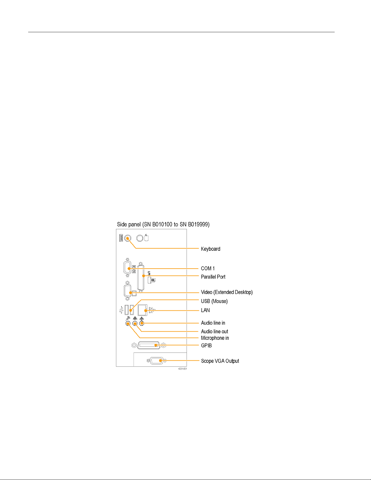
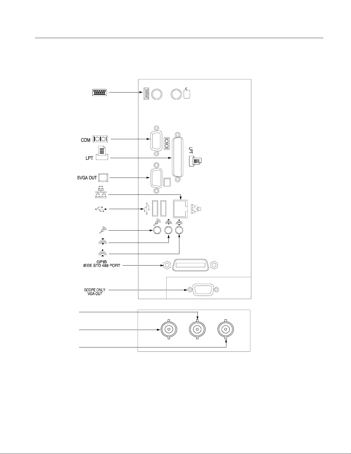
Connect the Peripherals
The peripheral connections are the same as those you would make on a personal
computer. The connection points are shown in Figure 2--1 on page 2--3. See
Table 2--1 for additional connection information.
Table 2-1: Additional accessory connection information
Item Description
Monitor If you use a non-standard monitor, you may need to change the
the display settings to achieve the proper resolution for your
monitor.
External Printer Connect the printer to the EPP (enhanced parallel port)
connector directly. If your printer has a DB-25 connector, use
the adapter cable that came with your printer to connect t o the
EPP connector. For information on printer usage, see Printing
Waveforms in your user oscilloscope manual.
Rackmount Refer to the TDS5000B Rackmount Installation Instructions for
information on installing the rackmount kit.
Other Refer to the Application release notes on your product CD set
for possible additional accessory installation information not
covered in this manual.
2- 2
NOTE. We recommend that you plug USB devices dir ectly into the USB connectors on the oscilloscope chassis for improved reliability rather than connecting
the devices serially in a chain. If your mouse locks up, disconnect and reconnect
the USB connector to restore normal operation. If the oscilloscope front panel
and/or touch screen do not respond, press the On/Standby switch for at least
5 seconds to cycle power.
WARNING. To prevent injury to yourself or the oscilloscope, power off the
oscilloscope. before installing accessories (such as the mouse and keyboard) to
connectors. See Powering Off the Oscilloscope on page 2--4.
TDS5000B Series Service Manual
Page 62
Operating Information
Description
Keyboard
COM 1
Parallel Port
Video (Extended
Desktop)
LAN
USB (Mouse)
Microphone in
LocationsIcon/Label
Side panel
Audio line out
Audio line in
GPIB
Scope VGA Output
Rear panel
Trigger signal
output (AUX OUT)
Timebase reference
input (EXT REF)
CH 3 signal output
(SIGNAL OUT)
Figure 2-1: Locations of peripheral connectors on the side panel
TDS5000B Series Service Manual
2- 3
Page 63
Operating Information
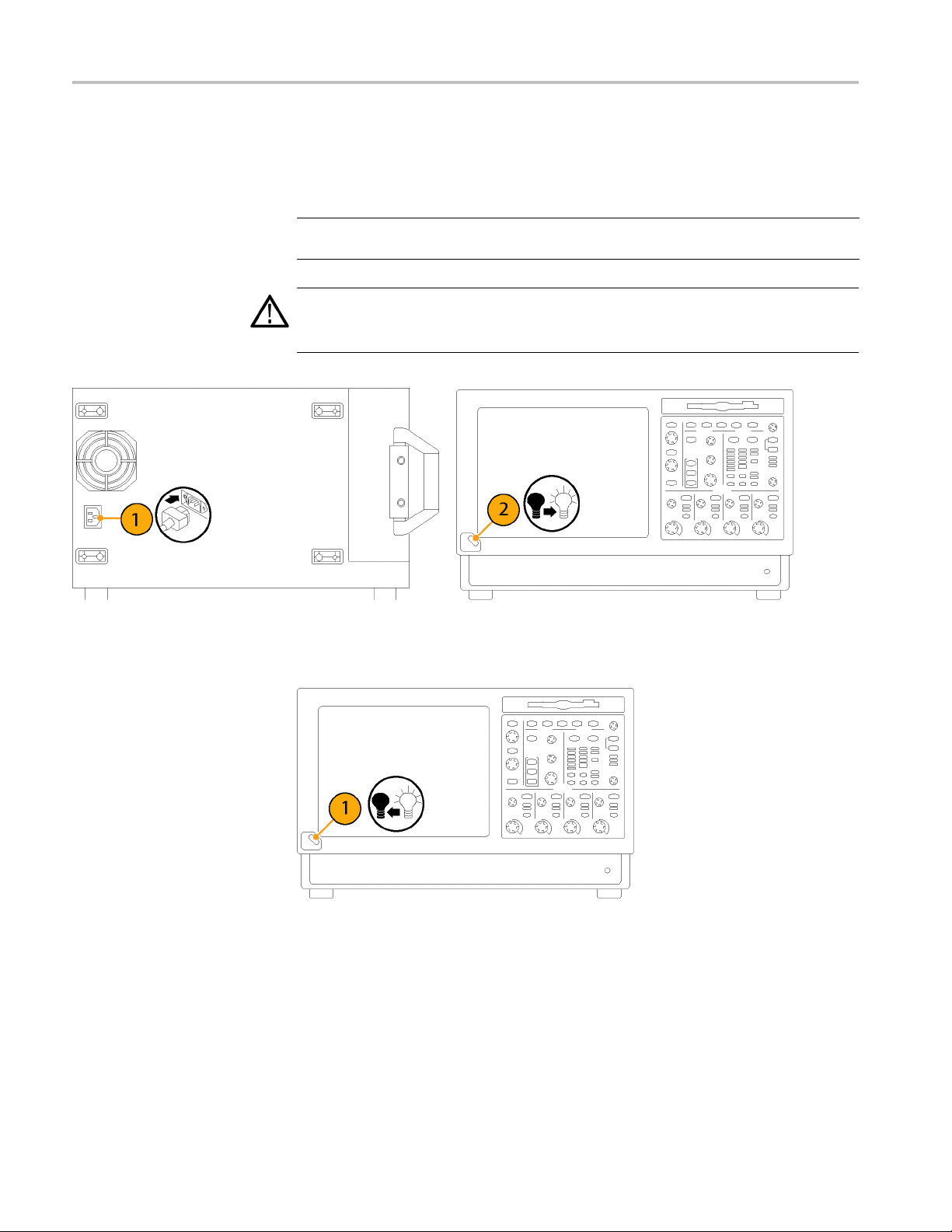
Power On the Instrument
Switch
Follow these steps to power on the instrument.
CAUTION. To prevent damage to the oscilloscope, connect the keyboard, mouse,
and other accessories before applying power to the product.
1. Connect the power cord.
2. If you have an external monitor, connect the power cord and power on the
monitor.
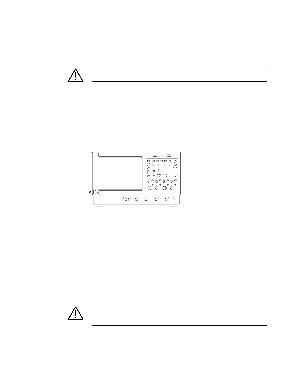
3. Press the On/Standby switch to power on the instrument (see Figure 2--2 for
the switch location).
4. Wait for the boot routine and low-level self test to complete.
Powering Off the
Oscilloscope
Create an Emergency
Startup Disk
Figure 2-2: On/Standby switch location
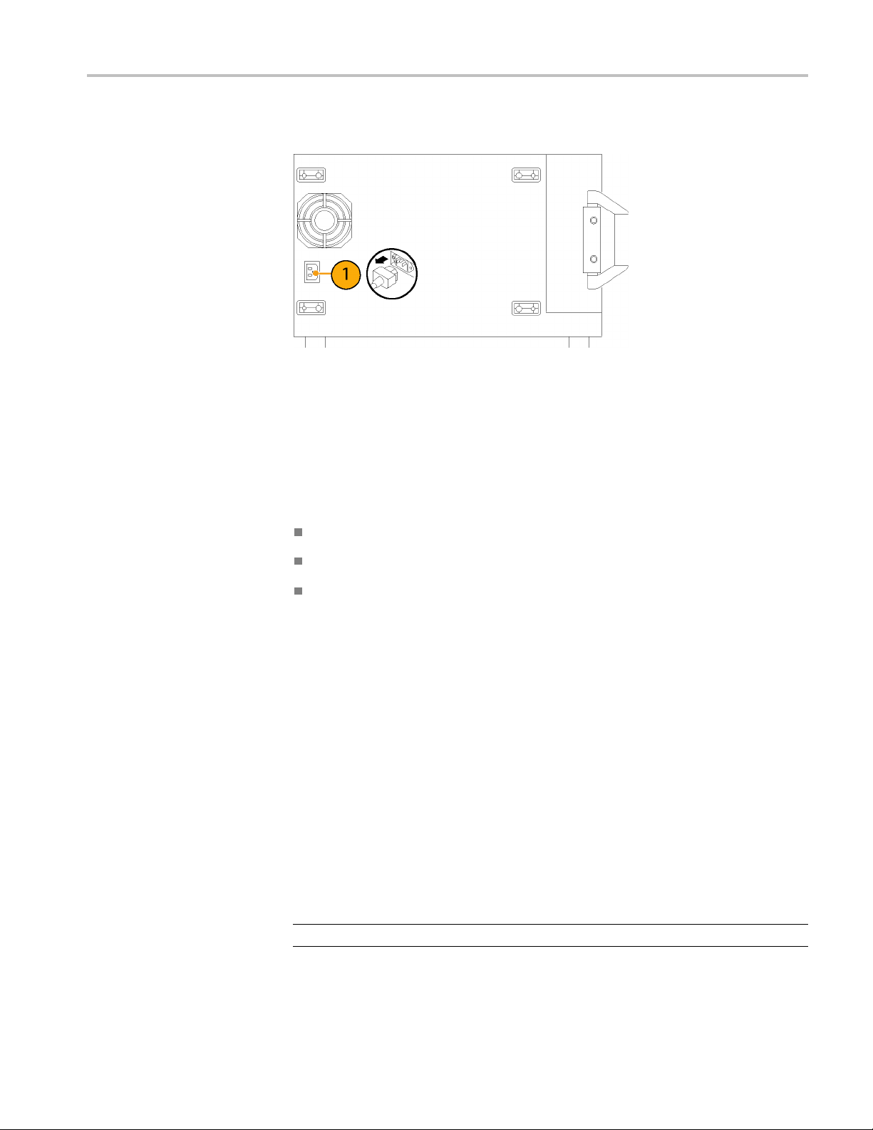
The oscilloscope has a built-in soft power-off function that safely powers off the
oscilloscope when you press the On/Standby switch.
To completely remove power to the instrument, press the On/Standby switch,
and then remove the power cord from the rear panel.
Now that you have completed the basic installation process, you should create an
emergency startup disk that you can use to restart your instrument in case of a
major hardware or software failure. You should create this disk, and then store it
in a safe place.
CAUTION. To prevent rebuilding the entir e instrument hard disk, create an
emergency startup disk and store it in a safe place. This disk may allow you to
recover your Windows installation.
The emergency startup disk contains basic files to restart your instrument. It also
contains files to check and format the hard disk.
2- 4
TDS5000B Series Service Manual
Page 64

Operating Information
Follow these steps to create the emergency startup disk:
1. Minimize the oscilloscope application: select Minimize from the File menu.
2. Select the Windows Start button, point to Programs >Accessories > System
Tools > Backup.
3. Select Emergency Repair Disk.
4. Insert a floppy disk into the disk drive and follow the on-screen instructions
to create the startup disk.
Software Installation
This section describes how to install the system software found on the productsoftware CD that accompanies this product. The instrument ships with the
product software installed, so only perform these procedures if reinstallation
becomes necessary.
Software Release Notes. Read the software release notes README.TXT ASCII
file on the product-software CD before performing installation procedures. This
file contains additional installation and operation information that supercedes
other product documentation.
To view the README.TXT file, open the Notepad Windows accessory and open
the file on the product-software CD. After installation, you can also read the
copy from a directory on the product:
C:\Program Files\Tektronix\TekScope\readme.txt
Operating System Restoration. Use the procedure that accompanies your
Operating System Restore CD should reinstalling system software become
necessary.
The compact disc contains the files necessary to restore the Windows operating
system and necessary drivers for the oscilloscope.
TDS5000B Series Service Manual
The Windows operating system and drivers are factory installed on the
oscilloscope hard disk. The compact disc serves as a backup in the event that you
have to rebuild the hard drive. You must restore the Windows operating system
before you can install the oscilloscope firmware and other product software.
Application Installation. Use the procedures that accompany your Product
Software CD should reinstalling the oscilloscope application software become
necessary.
The compact disc contains the files necessary to restore the oscilloscope
application and other software for the oscilloscope.
2- 5
Page 65

Operating Information
Operating Information
Software Lock for Upgrades. You can use the LockUpgrades utility to prevent
users from installing unauthorized firmware upgrades on the instrument. This
utility requires that a user enter a password before an upgrade can be installed.
To use the utility, run the LockUpgrades.exe file, and follow the on-screen
instructions. The LockUpgrades.exe file is in the following directory:
C:\Program Files\Tektronix\TekScope
NOTE. Using the Operating System Restore CD to reinstall the operating system
resets the LockUpgrades utility to the default setting and allows firmware
upgrades without password protection.
This section covers basic operation information so that you can operate and
prepare to service the instrument.
Back Up User Files
You should always back up your user files on a regular basis. Use the Microsoft
Backup tool to back up files stored on the hard disk. The Backup tool is located
in the System Tools folder in the Accessories folder.
1. Minimize the oscilloscope application by selecting Minimize from the File
menu.
2. Select the Windows Start button, point to Programs, Accessories, System
Tools, and then click Backup.
3. Use the Microsoft Backup tool to select your backup media and to select the
files and folders that you want to back up. Use the online help for information on using the Backup tool. You can back up to the floppy drive, CDRW
drive, or to your network storage.
2- 6
TDS5000B Series Service Manual
Page 66
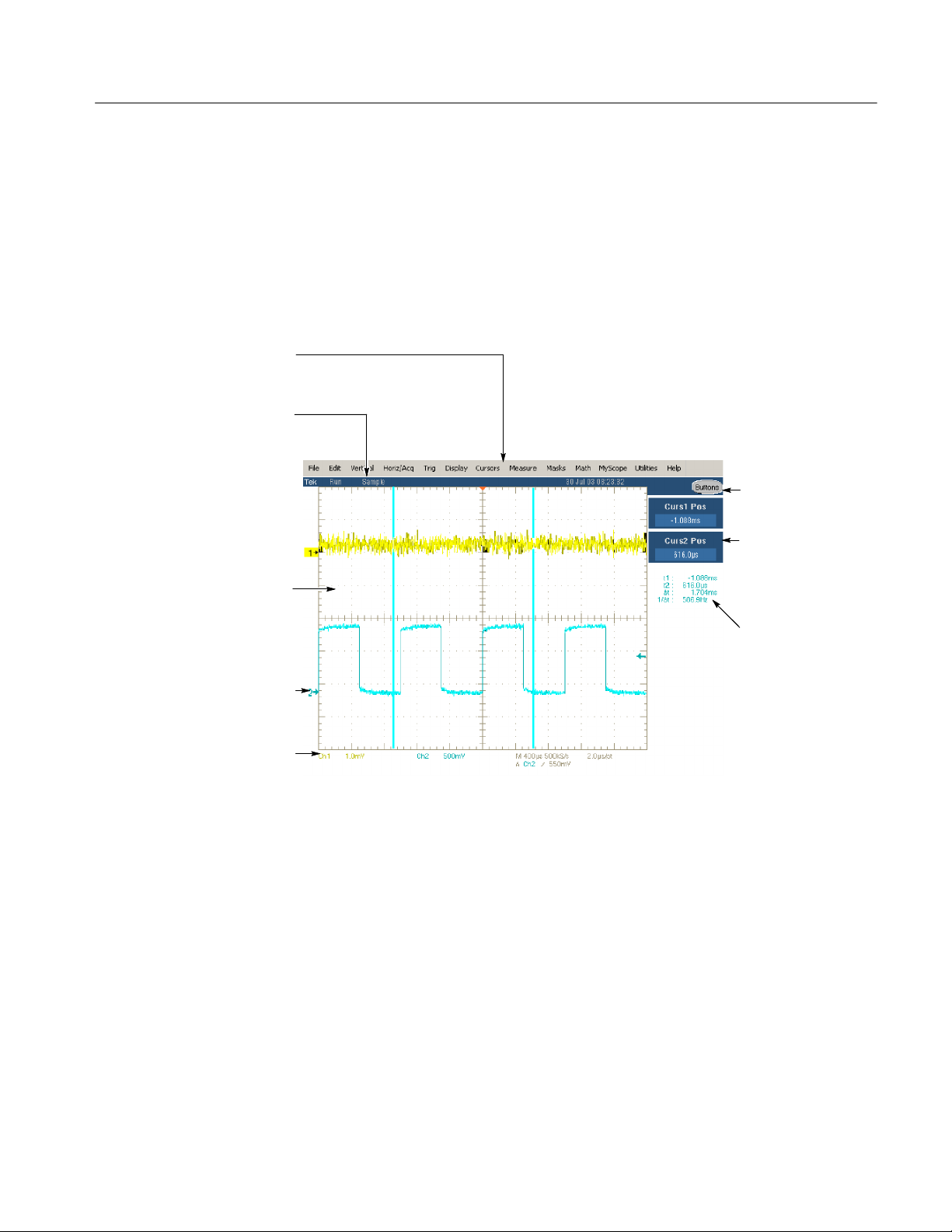
Operating Information
User Interface Map
Menu Bar: Access to data I/O,
printing, online help system, and
oscilloscope functions here
Status Bar: Display of
acquisition status, mode, and
number of acquisitions; trigger
status; date; and time
Display: Live, reference, & math
waveforms display here, along
with cursors
Waveform Handle: Click and drag to
change vertical position of waveform.
Click the handle and change the
position and scale using the
multipurpose knobs
Controls Status: Quick reference to
vertical, horizontal, and trigger
selections, scale, and parameters
This section shows the main parts of the user interface.
Figure 2--3 shows the oscilloscope in the Menu bar mode. All features of the
oscilloscope can be accessed through the menus using a mouse or the optional
touch screen.
When the oscilloscope is in the Toolbar mode, most of the control windows can
be accessed by touching buttons at the top of the display.
Buttons/Menu. Click to
toggle between tool-bar
and menu-bar modes
Multipurpose Knob
Readouts. Adjust
parameters controlled by
multipurpose knobs
Readouts: Display
cursor readouts and
measurement
readouts in this area,
selectable from the
menu bar or toolbar
If a control menu is
displayed, these
readouts move to the
graticule area
Figure 2-3: User interface
TDS5000B Series Service Manual
2- 7
Page 67

Operating Information
Front Panel I/O Map
Rear Panel I/O Map
Figure 2--4 shows the input/output connectors and floppy disk drive location.
Front panel
Floppy
disk drive
Auxiliary
trigger input
Probe comp output
Ground terminalChannel inputs
Figure 2-4: Locations of input/output connectors on the front panel
Figure 2--5 shows the input/output connectors on the rear panel.
Rear panel
EXT REF
AUX OUT
SIGNAL OUT
scale and offset controlled
by CH3 controls
Figure 2-5: Locations of connectors on the rear panel
2- 8
TDS5000B Series Service Manual
Page 68

Operating Information
Front Panel Controls Map
Many of the oscilloscope functions can be controlled directly from the front
panel controls or in conjunction with the screen interface.
Use these buttons to start and stop acquisition or start a single
acquisition sequence. The ARM, READY, and TRIG’D lights
Turn knob to adjust waveform intensity.
Press button to turn Fast Acquisition on or off.
Use these knobs and buttons to set the trigger parameters. Push
ADVANCED to display additional trigger functions.
Press to return settings to default values.
Horizontally scale, position, delay, and set record length
Press to automatically set up the vertical, horizontal, and trigger
controls based on selected channels.
show the acquisition status.
Press to turn cursors on or off.
Press to make a hard copy.
(resolution) of selected waveform.
Turn the multipurpose knobs to adjust parameters selected from
the screen interface. Press a Fine button to toggle between
normal and fine adjustment with its multipurpose knob.
Press MultiView Zoom to add a magnified graticule to the
display. Press HORIZ or VERT to select the axis to magnify.
Press to turn the touch screen on and off.
Turn channel displays on and off. Vertically scale, position, or
change the input termination.
Figure 2-6: Front panel controls
TDS5000B Series Service Manual
2- 9
Page 69

Operating Information
Instrument Diagnostics
Do the following steps to verify the instrument passes the internal diagnostics.
1. Display the diagnostics menu:
H If the oscilloscope is in toolbar mode, click the MENU button to put the
oscilloscope into the menu bar mode.
H Select Instrument Diagnostics . . . from the Utility menu.
2. Run the diagnostics.
H First disconnect any input signals from all four channels.
H Click the Run button in the diagnostics control window.
3. Wait for the diagnostics to complete.
The internal diagnostics do an exhaustive verification of proper
oscilloscope function. This verification may take several minutes to
complete. When the verification is finished, the resulting status appears
in the diagnostics control window.
4. Verify that no failures are found. If any failures occur, use the “DIAG:RESULTS:VERBOSE?” query for details on the errors.
Signal Path Compensation
Run the Signal Path Compensation.
NOTE. The oscilloscope must be warmed up to operating temperature. Signal
Path Compensation is not valid until the oscilloscope Calibration Status reaches
Temp status.
1. Select Instrument Calibration . . . from the Utility menu.
2. Verify that the instrument has had a twenty-minute warm-up before
continuing.
3. Click the Calibrate button to start the routine.
4. Wait for the test to complete (the test may take several minutes to complete).
5. Verify that the word Pass appears under the Status label in the control
window.
2- 10
TDS5000B Series Service Manual
Page 70

Operating Information
Using the Online Help
The user manual represents only part of the assistance available to you — the
online help system, integrated as part of the oscilloscope user interface, provides
quick-to-access support for operating this oscilloscope.
Two types of online help are available, the oscilloscope online help and the
GPIB online programmer’s help. The oscilloscope online help provides
information on all of the oscilloscope controls and procedures for doing typical
tasks. The GPIB online programmer’s help is normally installed on a remote PC
and provides information for controlling the oscilloscope via the GPIB. This
section mainly discusses the online help for the oscilloscope.
Accessing Help in the Toolbar Mode. When the oscilloscope is in the toolbar
mode, click the Help button in the upper right corner of the screen to display
help on whatever control window is displayed. F rom within the Help window,
you can access other help through tabs, links, or buttons. You can also click the
Help Topics button to display the standard Windows C ontents, Index, and Find
tabs.
Accessing Help in the Menu Bar Mode. When the oscilloscope is in the menu bar
mode, you can access the help system from the drop-down help menu. Select
Help on Window to display help on the current control window. Select Contents
and Index to display the standard Windows Contents, Index, and Find tabs. You
can also select other topics from the Help menu such as information on Technical
Support or product specifications.
Moving the Help Topics to View the Oscilloscope Display. You may temporarily
move any displayed help out of the w ay while you change control window
settings. Click the Minimize button in the help window to shrink the help
window to a button that displays in the upper right corner of the display (with
the label Restore Help). Click the Restore Help button to restore the help
window to its normal size.
TDS5000B Series Service Manual
2- 11
Page 71

Operating Information
2- 12
TDS5000B Series Service Manual
Page 72

Theory of Operation
Page 73

Page 74

Theory of Operation
This section describes the electrical operation of the oscilloscope. Figure 9--1 on
page 9--2 shows the module interconnections.
Logic Conventions
The oscilloscope contains many digital logic circuits. This manual refers to these
circuits with standard logic symbols and terms. Unless otherwise stated, all logic
functions are described using the positive-logic convention: the more positive of
the two logic levels is the high (1) state, and the more negative level is the low
(0) state. Signal states may also be described as “true” meaning their active state
or “false” meaning their nonactive state. The specific voltages that constitute a
high or low state vary among the electronic devices.
Module Overviews
Module overviews describe the basic operation of each functional circuit block
asshowninFigure9--1onpage9--2.
General
Input Signal Path
Display Panel
A PC motherboard and microprocessor system controls the oscilloscope. The
oscilloscope features a VGA resolution flat-panel display, an optional transparent
touch screen, and a front-panel with direct access to commonly used oscilloscope
functions. You can also use the oscilloscope with a mouse pointing device or
keyboard.
A signal enters the oscilloscope through a direct coaxial connection to the input
connector, or a probe connected to the front panel.
Acquisition Board. The acquisition board conditions the input signals, samples
them, converts them to digital signals, and controls the acquisition process under
direction of the processor system. The acquisition system includes the multisource trigger, acquisition timebase, and acquisition-mode generation and control
circuitry. The acquisition board is located in the bottom compartment of the
oscilloscope. Two or four vertical channels are accommodated. All channels
feature a Tekprobe Level 2 interface for additional front-end signal conditioning
functions like high input-impedance real-time probes.
Waveforms and menus are displayed on a 10.4 inch, color, active-matrix LCD
(liquid crystal display) with an optional integral touch panel.
TDS5000B Series Service Manual
3- 1
Page 75

Theory of Operation
Display System. Text and waveforms are processed by different parts of the
display circuitry. The display system (display adapter board and inverter board)
sends the text and waveform information to the display panel.
Touch Panel (Optional). The display board sends information from the touch panel
to the processor. Any changes in settings are reported to the processor system.
Front Panel
The software that operates on the PC motherboard reads the front-panel switches
and encoders. Any changes in their settings are reported to the processor system.
The software also turns the LEDs on and off.
Menu Switches. Front-panel menu switches are also read by the software. The
touch screen processor sends any changes in menu selections to the processor
system. The ON/STBY switch passes through the PC Interface board to the PC
motherboard. The PC motherboard creates the signal sent to the power supply to
toggle power.
Processor System. The processor system is a collection of hardware, software,
and the Windows operating system. The processor system provides a C PU for
performing calculations on data, floppy and CDRW disk drives for data storage,
and I/O for interacting with data. The disk drives, the PC interface board, the
motherboard, and any peripherals are all components of the processor system.
Floppy Drive. The floppy drive provides access to stored waveform data and
software to customize your oscilloscope.
PC Interface Board. The PC Interface board provides a data path between to the
Acquisition board and the display system. The PC Interface board provides a
GPIB interface through a side panel connector.
3- 2
PC Motherboard. The PC motherboard provides standard Windows functionality
and I/O port interfaces to the rear panel. The PC motherboard also reads the
front-panel switches and encoders and implements any changes requested by
their settings.
TDS5000B Series Service Manual
Page 76

Theory of Operation
Side Panels
Power Supply
The hard drive and CD-ROM provide access to stored waveform data and
software to customize your oscilloscope with your measurement needs. The
GPIB port allows for external control of the oscilloscope.
You can make hardcopies on the GPIB, RS-232, and Centronics ports. The PC
Interface board includes a VGA connector for an external monitor to display the
oscilloscope screen.
The PC motherboard has two USB ports and one serial port on the side panel.
A microphone input and earphone output exist on the PC motherboard.
The Ethernet connector is RJ-45. Keyboard and mouse are both PS/2.
The power supply is a switching power converter with active power factor
control. It supplies power to all of the circuitry in the oscilloscope.
The ON/STBY switch, located on the front panel, controls all of the power to
the oscilloscope except for part of the circuitry in the standby power supply.
The power supply sends a Good signal to the processor system when the power
supply voltages are within specifications.
Power is distributed through the PC Interface board and the Disk Drive Adapter
board connectors.
Fans
Printer
The fan assembly provides forced air cooling for the oscilloscope. The fans are
controlled by the microprocessor.
The optional internal thermal printer allows for quick hard copies of the screen
display. The printer receives power and USB signals from the PC Interface
board.
TDS5000B Series Service Manual
3- 3
Page 77

Theory of Operation
3- 4
TDS5000B Series Service Manual
Page 78

Performance Verification
Page 79

Page 80

Performance Verification
The performance verification procedures for this instrument are now available on
the TDS5000B S eries Product Software CD-ROM (Tektronix part number
063-3692-xx) that shipped with your product.
Look for the TDS5000B Series Digital Phosphor Oscilloscopes Specifications
and Performance Verification Technical Reference PDF, available on this disk.
TDS5000B Series Service Manual
4- 1
Page 81

Performance Verification
4- 2
TDS5000B Series Service Manual
Page 82

Calibration Procedure
Page 83

Page 84

Calibration Procedure
This chapter describes a sample automatic calibration procedure for your
oscilloscope. The purpose of this procedure is to make internal configuration
adjustments in the oscilloscope to help ensure its accuracy.
Calibration Interval
Calibration Environment
Calibration Dependencies
The voltage and timing references inside the oscilloscope are very stable
over time and should not need routine calibration/adjustment. Before performing
the procedures in this chapter, first verify that the oscilloscope does not meet
specifications. Refer to Performance Tests for a procedure to verify the specifica-
tions. These tests are part of the TDS5000B Series Digital Phosphor Oscillo-
scopes Specifications and Performance Verification Technical Reference PDF,
available on the TDS5000B Series Product Software CD-ROM.
If periodic calibration is one of your requirements, a general rule is to verify
performance and perform calibration (only if needed) every 2000 hours of
operation or once a year if the oscilloscope is used infrequently.
The oscilloscope must be calibrated in a 20 °Cto30°C ambient temperature
environment. The oscilloscope and signal source must warm up at least
20 minutes in this environment before you begin the calibration procedure.
Some calibration tests may be dependent upon others. The automatic calibration
procedure performs the tests in an appropriate sequence to eliminate dependency
problems. Always execute the complete automatic calibration procedure. The
total time to execute the procedure is approximately 45 minutes (depending
somewhat on the processor speed of the controller and the type of GPIB
controller — USB is much slower).
Calibration After Repair
TDS5000B Series Service Manual
After removal and replacement of a module due to electrical failure, you may
need to perform the calibration procedure, depending on the module replaced.
See Table 5--1.
Table 5-1: Calibration required for module
replaced
Module replaced Calibration required
Front panel assembly No
Acquisition board Ye s
Processor board Yes
5- 1
Page 85

Calibration Procedure
Table 5-1: Calibration required for module
replaced (Cont.)
Module replaced Calibration required
Required Equipment
Micro ATX processor assembly
Display panel or display
system
Power supply No
Interconnect boards No
Fans No
No
No
The sample calibration procedure requires the specific test equipment and
materials listed in Table 5--2.
Table 5-2: Required equipment and materials
Category Specific equipment required Quantity
Signal source Wavetek 9500 Oscilloscope Calibrator, with Option 100
(high-stability time base)
Wavetek 9520 or 9530 Standard Output Module 4ea
Instrument
controller
PC-compatible computer with National Instruments
GPIB Cont roller c ard and National Instruments NI-488.2
for Windows software, running Windows 95 or later.
1ea
1ea
5- 2
The PC must support Visual Basic win32 applications
and be able to provide a TekVisa supported GPIB
connection to the Wavetek 9500 as well as to the
TDS5000B oscilloscope
Test software Calibration software such as the sample Visual Basic 6
program list ed later in this chapter
TekVisa drivers. These are available on the TDS5000B
Application CD
GPIB cables GPIB cable, 1 m minimum length, Tektronix part number
002-0991-01 or similar
TDS5000B Series Service Manual
1ea
1ea
2ea
Page 86

Overview of the Procedure
To execute the sample calibration program listed at the end of this chapter, you
must have the specific equipment listed in Table 5--2. You must use a separate
computer as the instrument controller.
The sample program allows the user to control both the Wavetek 9500 and the
TDS5000B oscilloscope to achieve “Factory Calibration” of the TDS5000B.
There is no validation of the accuracy of the calibration preformed. That is, there
is no performance validation within this sample calibration program.
After the controller is set up, you need to install the TekVisa drivers from a
CD-ROM that was shipped with the oscilloscope. You also need to input and
compile your calibration software, such as the sample program listed later in this
chapter.
The sample procedure listed is fully automated. Once the program is started, all
of the steps will run without manual intervention.
Calibration Procedure
Instrumentation Setup
Controller
Before you can execute the sample calibration program, you need to set up and
configure the instrumentation. Make connections according to Figure 5--1.
GPIB cables daisy-chained onto
the oscilloscope GPIB connector
GPIB cableGPIB cable
Oscilloscope
Connect Wavetek
9520 or 9530 output
modules to the
oscilloscope CH 1
through CH 4 inputs as
shown
Wavetek 9500
Figure 5-1: Calibration setup
TDS5000B Series Service Manual
5- 3
Page 87

Calibration Procedure
Once the connections have been made, follow these steps:
NOTE. If you have just completed the performance verification procedure, you
can skip all the following steps in this setup procedure.
1. Power on the instruments: Turn power on for the controller, oscilloscope,
and signal source. The oscilloscope and the signal source must warm up for
20 minutes before you can begin to execute the test. However, while you are
waiting you can continue with the next s teps in this procedure.
2. Ensure that the Wavetek output modules are aligned in time with each other.
To do this, perform the Wavetek 95000 precision alignment 9500 channel
outputs, zero skew operation. Refer to the Wavetek 9500 documentation for
information about doing this procedure.
3. Check the Wavetek 9500 GPIB address: Refer to the Wavetek 9500
documentation for information about setting the GPIB address. If the address
is set to 0 or 1, change it to an address between 2 and 30 (inclusive). Make a
note of the address setting for use later in this procedure.
4. Set the GPIB address of the oscilloscope.
a. If the oscilloscope powered on in the toolbar mode (the default mode),
click the Menu button (upper right corner of the display) to put the
oscilloscope in menu-bar mode. In menu-bar mode, you should then see
a PC-style menu bar across the top of the display.
b. Pull down the Utility menu and then select GPIB Configuration . . . .
This command will display the GPIB Configuration control window.
c. In the GPIB Configuration control window, click the Talk/Listen button
to select Talk/Listen mode.
d. Click the Address readout and then click the up and down arrows or the
upper multipurpose knob to set the GPIB address to 1.
e. Click the Close button to close the control window.
5. Configure the PC controller: Use the GPIB software and hardware on the
controller as necessary to make the following settings:
a. Set the controller GPIB address to 0.
b. Define GPIB devices and their addresses for compatibility with the test
program as shown in Table 5--3.
5- 4
TDS5000B Series Service Manual
Page 88

Table 5-3: GPIB devices required by test
program
Device name GPIB address
<controller> 0
DUT1 1
Calibration Program Installation and Execution
Follow these steps to install the calibration program on the instrument controller.
1. Locate the test program: Locate your calibration program. You can adapt the
sample program listed later in this chapter. Put the program in an appropriate
location such a folder labelled c:\programfiles\tds5000b.
2. Once the instrumentation is connected and configured, allow it to warm up
for at least 20 minutes.
Calibration Procedure
3. Start the program 1: Select Run... in the Start menu and then enter
c:\programfiles\tds5000b\calibrate.exe (or other appropriate designation
for the disk drive, path and program name used if it is not c:\programfiles\tds5000b\calibrate.exe). (Some PCs and controllers require quotes
around the path.)
4. Start the program 2: Alternatively, open the directory used and then locate
the your calibration program. This is the file you will double click to execute
the calibration procedure.
5. For the sample program, program execution is a matter of pressing the “start
calibration” button.
Calibration Program Operation
The sample calibration application has two buttons. One starts the calibration
process, and one exits the application.
There are two text output windows. The first supports a scrolling step/status list.
The second has an update of the current status including a display of a simple
progress bar during the calibration.
TDS5000B Series Service Manual
Press the “Start Calibration” button: After pressing this button, all buttons
become inactive until calibration is complete.
The application checks GPIB communication with the TDS5000B oscilloscope
and the Wavetek 9500 to insure that it can control these devices and reports in
5- 5
Page 89

Calibration Procedure
the output window the response of these devices. As each step is performed, the
output window will have test signal requirements display and, after the
TDS5000B has completed that calibration step, the results will be displayed.
That is a scrolling history window and the results from the complete calibration
can be reviewed.
The status window will display a rough progress bar during calibration. Some
calibration steps can take more than 11 minutes and the status window is only
updated between steps, so be patient.
Locate your calibration program. You can adapt the sample program listed on
page 5--37. Put the program in an appropriate location such as a folder labeled
c:\programfiles\tds5000b.
5- 6
TDS5000B Series Service Manual
Page 90

Commands
This section supports the GPIB commands with command definitions, syntax,
return messages, and examples. The commands are divided into two groups -CALibrate and DIAGnostic.
Calibration Command Group
The calibration commands provide information about the current state of
calibration. Table 5--4 lists the CALibrate commands, and descriptions and
examples follow the table.
Table 5-4: CALibrate commands
Command Description
*CAL? Instructs the instrument to perform self-calibration
CAL? Returns the internal and factory calibration status
CALibrate:CALProbe:CH<x>?
CALibrate:FACtory Start t he factory calibration
CALibrate:FACtory:ABOrt Stop the factory calibration without changing the cal
CALibrate:FACtory:CONTInue Do the next step in the calibration procedure
CALibrate:FACtory:NOTify:DUE? Return whether the factory calibration is due
CALibrate:FACtory:NOTify:HOURs Set or return the number of hours until the user is
and the calibration due date
Instructs the instrument to perform a probe
calibration
file
notified that the instrument is due for factory
calibration
TDS5000B Series Service Manual
CALibrate:FACtory:NOTify:YEARs Set or return the number of years until the user is
notified that the instrument is due for factory
calibration
CALibrate:FACtory:PREVious Backup to the previous step/group but don’t go until
a CONTINUE command is sent
CALibrate:FACtory:STARt Start the factory cal ibration
CALibrate:FACtory:STATus? Return the factory calibration status
CALibrate:FACtory:STEPSTATus? Return the status of the current calibration step
CALibrate:FACtory:STEPSTIMulus? Return the required stimulus for this calibration step
CALibrate:INTERNal Starts the internal signal path calibration
CALibrate:INTERNal:STARt Starts the internal signal path calibration
5- 7
Page 91

Commands
*CAL?
Table 5-4: CALibrate commands (Cont.)
Command Description
CALibrate:INTERNal:STATus? Returns the current status of the internal signal path
calibration
CALibrate:PROBEstate:CH<x> Returns the calibration status of the attached probe
CALibrate:RESults? Returns the status of all calibration subsystems
without performing an SPC operation
CALibrate:RESults SPC? Returns the results of the last SPC operation
This query-only command instructs the digitizing oscilloscope to perform a
signal path compensation and return its calibration status. This command is
equivalent to selecting Instrument Calibration from the Utilities menu and then
clicking the Calibrate button.
Related Commands
Syntax
Returns
Example
NOTE. The self-calibration can take several minutes to r espond. No other
commands will be executed until calibration is complete.
CALibrate:RESults:SPC?
*CAL?
0 <NR1> indicating that the calibration did not complete successfully
1 (or any non-zero value) <NR 1> indicating that the calibration completed
without errors
*CAL?
might return
1
indicating that the calibration was successful.
5- 8
TDS5000B Series Service Manual
Page 92

CAL?
Commands
This query-only command instructs the instrument to return the internal and
factory calibration status and the calibration due status.
Related Commands
Syntax
Returns
Example
CALibrate:RESults:SPC?
CAL?
0 <NR1> indicating that the calibration did not complete successfully
1 (or any non-zero value) <NR 1> indicating that the calibration completed
without errors
*CAL?
might return
*CALIBRATE:INTERNAL:STATUS PASS;:CALIBRATE:FACTORY:STATUS
PASS;NOTIFY:HOURS 2000;YEARS 1.0E0;DUE 0
indicating the internal and factory calibration status and the calibration due
status.
CALibrate:CALProbe:CH<x>?
Related Commands
Syntax
Returns
TDS5000B Series Service Manual
This query-only command instructs the instrument to perform a probe calibration
for the selected channel and returns the calibration status. The Channel <x>
range is 1--4. This command is equivalent to selecting Probe C al from the
Vertical menu. You must warm up the instrument for at least 20 minutes before
running this command.
A probe query takes approximately 30 seconds to complete. No other commands
will be executed until calibration is complete.
CH<x>:PROBECal?, CALibrate:PRObestate:CH<x>?
CALibrate:CALProbe:CH<x>?
--1 indicating that the probe calibration failed for the selected channel
0 indicating that the probe calibration passed for the selected channel
1 indicating that the probe calibration is initialized for the selected channel
5- 9
Page 93

Commands
Examples
CALibrate:CALProbe:CH2?
might return
:CALIBRATE:CALPROBE:CH2 0
indicating that the probe calibration passed for Channel 2.
CALibrate:FACtory
This command starts the factory calibration. This command functions the same
as the CALibrate:FACtory:STARt command.
Syntax
Example
CALibrate:FACtory
CALIBRATE:FACTORY
starts the factory calibration
CALibrate:FACtory:ABOrt
This command stops the factory calibration, resets to the initialization state, and
exits without changing the calibration data.
Related Commands
Syntax
Example
CALibrate:FACtory:STARt
CALibrate:FACtory:ABOrt
CALIBRATE:FACTORY:ABORT
stops the factory calibration
CALibrate:FACtory:CONTInue
This command does the next step in the calibration procedure. The calibration
step number is increased on successful completion of this step. If the calibration
step fails, the step number is not increased. You can use CALibrate:FACtory:CONTinue, to repeat a factory calibration step that failed.
Follow this command with CALibrate:FACtory:STEPstatus? to determine
execution status.
5- 10
TDS5000B Series Service Manual
Page 94

Commands
If the current step is the last step and the calibration succeeds, new calibration
data and pass status is saved to non-volatile memory and the oscilloscope returns
to normal operation in the same state it was in before beginning factory
calibration.
If the current step is the last step and any factory calibration step has failed,
without a successful pass for repeated steps, a fail status will be saved to
non-volatile memory. Factory calibration data will not be saved to non-volatile
memory if the factory status is FAIL.
Related Commands
Syntax
Example
CALibrate:FACtory:STARt
CALibrate:FACtory:CONTinue
CALIBRATE:FACTORY:CONTINUE
causes the instrument to execute the next step in the calibration procedure.
CALibrate:FACtory:FANcontrol
This command sets or returns the status of the fan control.
Syntax 1
Arguments
Syntax 2
CALibrate:FACtory:FANcontrol <NR3> [, <NR3>]
<NR3> sets the temperature in degrees Celsius
<NR3> sets the mean sea level specified in feet; this command is optional and if
not specified, it defaults to 0.0 (sea level)
CALibrate:FACtory:FANcontrol?
Returns
Example 1
Example 2
TDS5000B Series Service Manual
0 means that the fan was never calibrated
1 means that calibration is in process
2 means that the fan has been calibrated
CALibrate:FACtory:FANcontrol 20
This sets the fan control calibration temperature to 20 degrees Celsius at sea
level.
CALibrate:FACtory:FANcontrol?
5- 11
Page 95

Commands
This query might return
:CALIBRATE:FACTORY:FANCONTROL 1
indicating that calibration is in process.
CALibrate:FACtory:NOTify:DUE?
This command returns whether the factory calibration is due.
Syntax
Returns
Example
CALibrate:FACtory:NOTify:DUE?
0 <NR1> means that the oscilloscope is not due for factory calibration.
1 <NR1> means that the oscilloscope is due for factory calibration.
CALIBRATE:NOTIFY:DUE?
might return
:CALIBRATE:FACTORY:NOTIFY:DUE 0
signifying that factory calibration is not due.
CALibrate:FACtory:NOTify:HOURs
This command sets or returns the number of hours until the user is notified that
the instrument is due for factory calibration.
Syntax
CALibrate:FACtory:NOTify:HOURs {INFInite|<NR1>}
5- 12
Argument
Example 1
Example 2
INFInite means whatever the specified maximum is for the instrument.
<NR1> set to an integer value.
CALIBRATE:NOTIFY:HOURS 1500
sets the calibration notification time to 1,500 hours.
CALIBRATE:FACTORY:NOTIFY:HOURS?
might return
TDS5000B Series Service Manual
Page 96

:CALIBRATE:FACTORY:NOTIFY:HOURS 2000
signifying that the calibration due notifier will be displayed 2000 hours after the
last calibration.
CALibrate:FACtory:NOTify:YEARs
This command sets or returns the number of years until the user is notified that
the instrument is due for factory calibration.
Commands
Syntax
Argument
Example 1
Example 2
CALibrate:FACtory:NOTify:YEARs {INFInite|<NR3>}
INFInite means whatever the specified maximum is for the instrument.
<NR1> set to a floating point value.
CALIBRATE:FACTORY:NOTIFY:HOURS 1.5e0
sets the calibration notification time to 1.5 years.
CALIBRATE:FACTORY:NOTIFY:HOURS?
might return
:CALIBRATE:FACTORY:NOTIFY:HOURS 1.5e0
signifying that the calibration due notifier will be displayed 1. 5 years after the
last calibration.
CALibrate:FACtory:PREVious
Syntax
Example
TDS5000B Series Service Manual
This command backs up the calibration steps one step so that the next CALibrate:FACtory:CONTInue command will repeat the factory calibration step that
just finished. Repeated CALibrate:FACtory:PREVious commands can back up as
many calibration steps as desired, at least until step one is reached. The
appropriate notifier, with signal source information, is displayed after the factory
calibration step is adjusted.
CALibrate:FACtory:PREVious
CALIBRATE:FACTORY:PREVIOUS
backs up the calibration steps one step.
5- 13
Page 97

Commands
CALibrate:FACtory:STARt
This command starts the factory calibration. The factory calibration process
consists of a series of steps. Do not send any other commands that change the
state of the oscilloscope until the calibration process is complete.
Related Commands
Syntax
Example
CALibrate:FACtory:ABOrt
CALibrate:FACtory:STARt
CALIBRATE:FACTORY:START
starts the factory calibration.
CALibrate:FACtory:STATus?
This command returns the factory calibration status.
Syntax
Returns
CALibrate:FACtory:STATus?
FAIL if the factory calibration failed
PASS if the factory calibration passed
UNCAL if the factory calibration has not been run
Example
CALIBRATE:FACTORY:STATUS
might return
:CALIBRATE:FACTORY:STATUS PASS
indicating the factory calibration passed
CALibrate:FACtory:STEPSTATus
This command returns the status of the current calibration step.
It returns pass during oscilloscope power on without regard to actual calibration
status. It returns pass or fail for the factory calibration step that most recently
executed when factory calibration is in progress. Use this query to synchronize
programmed factory calibration steps.
5- 14
TDS5000B Series Service Manual
Page 98

Commands
Syntax
Returns
Example
CALibrate:FACtory:STEPSTATus
FAIL if the factory calibration failed
PASS if the factory calibration passed
CALIBRATE:FACTORY:STEPSTATUS
might return
:CALIBRATE:FACTORY:STEPSTATUS FAIL
indicating the last oscilloscope calibration step did not pass
CALibrate:FACtory:STEPSTIMulus
This command returns the required stimulus for this calibration.
Syntax
CALibrate:FACtory:STEPSTIMulus
Returns
Using the format: <Volts>, <Freq>, <Chan>, <Term>, <Token>
Volts <NR3> is a floating point number representing DC volts if the value for
<Freq> is 0 or representing V
Freq <NR1> is the frequency in Hz of the applied waveform.
NOTE. This command typically returns the frequency of the signal in hertz.
However, if it returns a frequency value of “4” then that means apply the deskew
function of the Wavetek 9500 calibrator to all input channels. If it returns a “0”
then apply a DC voltage.
Chan <NR1> stands for the channel.
Term <NR1> stands for the ohms of termination. For example,
8.0E--03, 0, 1, 50, C01
means apply 800 mV DC to Channel 1 with 50 ohm termination. If the query is
sent before FACTORY CAL has been initialized, the returned string will be:
0.0, 0, 0, 0, END
Token is a unique string identifying the step to be done next.
peak-to-peak
if the value for <Freq> is non-zero.
TDS5000B Series Service Manual
5- 15
Page 99

Commands
CALibrate:INTERNal
This command starts the internal signal path calibration (SPC) of the instrument.
You can use the CALibrate:INTERNal:STATus? query to return the current
status of the internal signal path calibration of the instrument.
Syntax
Example
CALibrate:INTERNal
CALIBRATE:INTERNal
This command starts the internal signal path calibration of the instrument.
CALibrate:INTERNal:STARt
This command starts the internal signal path calibration (SPC) of the instrument.
This command is the same as the CALibrate:INTERNal command. You can use
the CALibrate:INTERNal:STATus? query to return the current status of the
internal signal path calibration of the instrument.
Syntax
Example
CALibrate:INTERNal:STARt
CALIBRATE:INTERNal:STARt
This command starts the internal signal path calibration of the instrument.
CALibrate:INTERNal:STATus?
This query-only command returns the current status of the instrument internal
signal path calibration for the last SPC operation.
Syntax
Returns
5- 16
CALibrate:INTERNal:STATus?
This query will return one of the following:
H INIT indicating that the instrument has not had the internal signal path
calibration run
H PASS indicating that the signal path calibration completed successfully
H FAIL indicating that the signal path calibration did not complete successfully
H WARMUP indicating that the instrument has not warmed up for the required
time to perform signal path calibration
TDS5000B Series Service Manual
Page 100

Commands
H TEMPDRIFT indicating that the instrument has not reached a state of stable
temperature adequate for performing signal path calibration
H RUNNING indicating that the signal path calibration is currently running
Example
CALIBRATE:INTERNal:STATus?
This query might return INIT, indicating that the internal signal path calibration
has not been run.
CALibrate:PRObestate:CH<x>?
This query-only command returns the status of the probe calibration for a probe
attached to a given channel.
Related Commands
Syntax
Arguments
Returns
CH<x>:PROBECal?
CALibrate:PROBEstate:CH<x>?
<x> is the channel number the probe is attached to
--1 indicating that the probe calibration failed for the selected channel
0 indicating that the probe calibration passed for the selected channel
1 indicating that the probe calibration is initialized for the selected channel
2 indicating that probe calibration is running for the selected channel
Example
CALibrate:RESults?
TDS5000B Series Service Manual
CALIBRATE:PROBESTATE:CH1?
This query returns the status of the probe calibration for a probe attached to
A query might return
:CALIBRATE:PROBESTATE:CH1 0
indicating that the probe calibration for channel 1 passed.
This query-only command returns the status of internal and factory calibration
without performing calibration operations. The returned results do not include
the calibration status of attached probes. The CALibration:RESults? query is
intended to support GO/NoGO testing of the instrument calibration readiness: all
returned results should indicate PASS status if the instrument is fit for duty. It is
CH1.
5- 17
 Loading...