

Page 1

x
TBS2000 Series
Oscilloscopes
ZZZ
User Manual
*P077114702*
077-1147-02
Page 2

Page 3

xx
TBS2000 Series
Oscilloscopes
ZZZ
User Manual
Register now!
Click the following link to protect your product.
► www.tek.com/register
www.tek.com
077-1147-02
Page 4

Copyright © Tektronix. All rights reserved. Licensed software products are owned by Tektronix or its subsidiaries or suppliers, and are
protected by na
tional copyright laws and international treaty provisions.
Tektronix pro
previously published material. Specifications and price change privileges reserved.
TEKTRONIX and TEK are registered trademarks of Tektronix, Inc.
TekVPI is a registered trademark of Tektronix, Inc.
TekSecure and TekSmartLab are trademarks of Tektronix, Inc.
ducts are covered by U.S. and foreign patents, issued and pending. Information in this publication supersedes that in all
Contacting Tektronix
Tektronix, Inc.
14150 SW Karl Braun Drive
P.O. Box 500
Beaverton, OR 97077
USA
For product i nformation, sales, service, and technical support:
In North America, call 1-800-833-9200.
Worldwide, visit www.tek.com to find contacts in your area.
Page 5

TBS2000 Series Oscilloscopes
Warranty
Tektronix warrants that the product will be free from defects in materials and workmanship for a period of five (5) years from the date of
original purchase from an authorized Tektronix distributor. If the product proves defective during this warranty period, Tektronix, at its
option, either will repair the defective product without charge for parts and labor, or will provide a replacement in exchange for the
defective product. Batteries are excluded from this warranty. Parts, modules and replacement products used by Tektronix for warranty
work may be new or reconditioned to like new performance. All replaced parts, modules and products become the property of Tektronix.
In order to obtain service under this warranty, Customer must notify Tektronix of the defect before the expiration of the warranty
period and make suitable arrangements for the performance of s ervice. C ustomer shall be responsible for packaging and shipping
the defective product to the service center designated by Tektronix, shipping charges prepaid, and with a copy of customer proof of
purchase. Tektronix shall pay for the return of the product to Customer if the shipment is to a location within the country in which
the Tektronix service center is located. Customer shall be responsible for paying all shipping charges, duties, taxes, and any other
charges for products returned to any other locations.
This warranty shall not apply to any defect, failure or damage caused by improper use or improper or inadequate maintenance and
care. Tektronix shall not be obligated to furnish service under this warranty a) to repair damage resulting from attempts by personnel
other than Tektronix representatives to install, repair or service the product; b) to repair damage resulting from improper use or
connection to incompatible equipment; c) to repair any damage or malfunction caused by the use of non-Tektronix supplies; or
d) to service a product that has been modified or integrated with other products when the effect of such modification or integration
increases the time or difficulty of servicing the product.
THIS WARRANTY IS GIVEN BY TEKTR ON IX WITH RES PEC T TO THE PRODUCT IN LIEU OF ANY OTHER WARRANTIES,
EXPRESS OR IMPLIED. TEKTRONIX AND ITS VENDORS DISCLAIM ANY IMPLIED WARRANTIES OF MERCHANTABILITY OR
FITNESS FOR A PARTICULAR PURPOSE. TEKTRONIX' RESPONSIBILITY TO REPAIR OR REPLACE DEFECTIVE PRODUCTS
IS THE SOLE AND EXCLUSIVE REMEDY PROVIDED TO THE CUSTOMER FOR BREACH OF THIS WARRANTY. T EKT RONIX
AND ITS VENDORS WILL NOT BE LIABLE FOR ANY INDIRECT, SPECIAL, INCIDENTAL, OR CONSEQUENTIAL DAMAGES
IRRESPECTIVE OF WHETHER TEKTRONIX OR THE VENDOR HAS ADVANCE NOTICE OF THE POSSIBILITY OF SUCH
DAMAGES.
Page 6

TPP0100 Probe
Warranty
Tektronix warrants that this product will be free from defects in materials and workmanship for a period of one (1) year from the date of
shipment. If any such product proves defective during this warranty period, Tektronix, at its option, either will repair the defective
product without charge for parts and labor, or will provide a replacement in exchange for the defective product. Parts, modules and
replacement products used by Tektronix for warranty work may be new or reconditioned to like new performance. All replaced
parts, modules and products become the property of Tektronix.
In order to obtain service under this warranty, Customer must notify Tektronix of the defect before the expiration of the warranty period
and make suitable arrangements for the performance of service. Customer shall be responsible for packaging and shipping the
defective product to the service center designated by Tektronix, with shipping charges prepaid. Tektronix shall pay for the return of the
product to Customer if the shipment is to a location within the country in which the Tektronix service center is located. Customer shall
be responsible for paying all shipping charges, duties, taxes, and any other charges for products returned to any other locations.
This warranty shall not apply to any defect, failure or damage caused by improper use or improper or inadequate maintenance and
care. Tektronix shall not be obligated to furnish service under this warranty a) to repair damage resulting from attempts by personnel
other than Tektronix r epresentatives to install, repair or service the product; b) to repair damage resulting from improper use or
connection to incompatible equipment; c) to repair any damage or malfunction caused by the use of non-Tektronix supplies; or
d) to service a product that has been modified or integrated with other products when the effect of such modification or integration
increases the time or difficulty of servicing the product.
THIS WARRANTY IS GIVEN BY TEKTRONIX WITH RESPECT TO THE PRODUCT IN LIEU OF ANY OTHER WARRANTIES,
EXPRESS OR IMPLIED. TEKTRONIX AND ITS VENDORS DISCLAIM ANY IMPLIED WARRANTIES OF MERCHANTABILITY OR
FITNESS FOR A PARTICULAR PURPOSE. TEKTRONIX' RESPONSIBILITY TO REPAIR OR REPLACE DEFECTIVE PRODUCTS
IS THE SOLE AND EXCLUSIVE REMEDY PROVIDED TO THE CUSTOMER FOR BREACH OF THIS WARRANTY. T EKTRONIX
AND ITS VENDO RS WILL NOT BE LIABLE FOR ANY INDIRECT, SPECIAL, INCIDENTAL, OR CONSEQUENTIAL DAMAGES
IRRESPECTIVE OF WHETHER TEKTRONIX OR THE VENDOR HAS ADVANCE NOTICE OF THE POSSIBILITY OF SUCH
DAMAGES.
Page 7

Table of Contents
Important safety information .......................................................................................................... v
Preface ................................................................................................................................. ix
Key features...................................................................................................................... ix
Terms in this manual ... . ... . ... . . . ... . ... . . . ... . ... . . . ... . ... . ... . .. ... . ... . . . ... . ... . ... . .. ... . ... . . . ... . ... . ... . .. ... . ... . . . ... x
Symbols and terms on the product . ... . ... . . . ... . ... . .. ... . ... . . . ... . ... . . . ... . ... . .. ... . ... . . . ... . ... . . . ... . ... . .. ... . ... . . . ... x
Conventions used in this manual ... . . . ... . ... . ... . . . ... . ... . ... . ... . .. ... . ... . ... . ... . .. ... . ... . ... . ... . .. ... . ... . ... . ... . .. ... . xi
Installation.............................................................................................................................. 1
Before installation ................................................................................................................ 1
Operating requirements . . . . ... . ... . .. ... . ... . . . ... . ... . . . ... . ... . .. ... . ... . . . ... . ... . . . ... . ... . .. ... . ... . . . ... . ... . . . ... . ... . .. ....... 4
Environment requirements. . .. ... . . . ... . ... . . . ... . ... . .. ... . . . ... . ... . . . ... . . . ... . ... . . . ... . ... . .. ... . . . ... . ... . . . ... . ... . . . ... . . 4
Power requirements.. . ... . . . ... . ... . .. ... . ... . . . ... . . . ... . ... . . . ... . ... . .. ... . ... . . . ... . ... . . . ... . . . ... . ... . .. ... . ... . . . ... . ... . . 4
Getting acquainted with the oscilloscope .. . .. ... . ... . ... . . . ... . ... . . . ... . ... . ... . ... . .. ... . ... . ... . ... . . . ... . ... . ... . ... . .. ... . ... . .. 5
Powering on and off the oscilloscope ........................................................................................... 5
Changing the user interface language . . ... . .. ... . ... . . . ... . ... . . . ... . ... . .. ... . ... . . . ... . ... . . . ... . ... . .. ... . ... . . . ... . ... . . . .. 6
Changing the date and time . . .. ... . ... . . . ... . ... . .. ... . ... . .. ... . ... . . . ... . . . ... . ... . . . ... . ... . .. ... . . . ... . ... . . . ... . . . ... . ... . . 9
Connecting probes to the oscilloscope . .. ... . ... . ... . .. ... . ... . ... . ... . .. ... . ... . ... . ... . .. ... . ... . ... . . . ... . ... . . . ... . ... . ... . 11
Reducing electrostatic damage while taking measuremens . . . ... . . . ... . . . ... . . . ... . . . ... . . . ... . . . ... . . . ... . . . ... . . . ... . 11
Doing a functional check.. . .. ... . ... . ... . . . ... . ... . . . ... . ... . ... . ... . .. ... . ... . ... . ... . .. ... . ... . ... . . . ... . ... . . . ... . ... . ... . ... 12
What isAutoset?........................................................................................................... 14
Compensating a passive voltage probe . . . ... . ... . . . ... . ... . . . ... . ... . ... . .. ... . ... . . . ... . ... . ... . .. ... . ... . . . ... . ... . ... . .. ... 15
Signal path compensation (SPC). . . ... . ... . ... . .. ... . . . ... . ... . . . ... . ... . . . ... . ... . .. ... . ... . . . ... . ... . . . ... . ... . .. ... . ... . . . .. 18
Getting on-screen help for settings: Help Everywhere ........................................................................ 19
The Scope Intro function........................................................................................................ 21
Sampling oscilloscope concepts ..................................................................................................... 22
Sampling andacquisition concepts ............................................................................................ 22
Trigger concepts .. . ... . ... . .. ... . ... . ... . ... . .. ... . ... . ... . . . ... . ... . . . ... . ... . ... . ... . .. ... . ... . ... . ... . .. ... . ... . ... . . . ... . ... 24
Trigger slope and level concepts. . ... . . . ... . ... . . . ... . ... . ... . . . ... . ... . .. ... . ... . ... . . . ... . ... . . . ... . ... . . . ... . ... . ... . .. 25
Setting channel input parameters. . .. ... . . . ... . ... . ... . . . ... . ... . . . ... . ... . ... . . . ... . ... . .. ... . ... . ... . . . ... . ... . . . ... . ... . ... . . . .... 28
Setting input signal coupling .. . . . ... . ... . ... . .. ... . ... . ... . . . ... . ... . . . ... . ... . ... . . . ... . ... . . . ... . ... . ... . . . ... . ... . . . ... . ... . . 28
Inverting the input signal .. . . . ... . ... . ... . . . ... . ... . . . ... . ... . ... . . . ... . ... . .. ... . ... . ... . . . ... . ... . . . ... . ... . ... . . . ... . ... . .. ... 28
ing the oscilloscope bandwidth. . ... . ... . .. ... . ... . ... . . . ... . ... . . . ... . ... . ... . ... . .. ... . ... . ... . ... . .. ... . ... . ... . . . ... . ... 29
Sett
Setting the probe type (voltage orcurrent)..................................................................................... 29
Setting the probe attenuation factor .. . .. ... . ... . ... . ... . .. ... . ... . ... . . . ... . ... . . . ... . ... . ... . ... . .. ... . ... . ... . ... . .. ... . ... . . 30
Quickly setting the probe attenuation to 1X or 10X. . . . ... . ... . ... . ... . .. ... . ... . ... . ... . .. ... . ... . ... . . . ... . ... . . . ... . ... . ... . 30
Setting the Measure Current mode for voltage probes ... . . . ... . ... . ... . . . ... . ... . .. ... . ... . . . ... . ... . . . ... . ... . . . ... . ... . . . .. 31
Setting the input signal vertical offset . ... . ... . . . ... . ... . .. ... . ... . ... . . . ... . ... . .. ... . ... . ... . . . ... . ... . .. ... . ... . ... . . . ... . ... 31
Setting the waveform vertical position.......................................................................................... 32
The difference between vertical position and vertical offset ............................................................. 32
Setting channel deskew. .. ... . ... . ... . . . ... . ... . . . ... . ... . ... . . . ... . ... . . . ... . ... . ... . . . ... . ... . . . ... . ... . ... . . . ... . ... . . . ... . .. 33
Trigger setup . ... . . . ... . ... . .. ... . ... . . . ... . ... . . . ... . . . ... . ... . .. ... . ... . . . ... . ... . . . ... . ... . .. ... . . . ... . ... . . . ... . ... . . . ... . ......... 34
Triggering on a waveform edge .. . ... . ... . ... . . . ... . ... . . . ... . ... . ... . ... . . . ... . ... . ... . ... . .. ... . ... . ... . ... . .. ... . ... . ... . ... 34
Triggering on a specifiedpulse width .......................................................................................... 35
Table of Content
s
TBS2000 Series User Manual i
Page 8

Table of Content
Acquisition setup...................................................................................................................... 38
Waveform display settings ........................................................................................................... 44
Analyzing a waveform . . .. ... . ... . . . ... . ... . ... . .. ... . ... . ... . . . ... . ... . . . ... . ... . ... . . . ... . ... . . . ... . ... . ... . . . ... . ... . . . ... . ... . .... 47
Saving data ........................................................................................................................... 63
s
Triggering on a runt pulse....................................................................................................... 36
Setting the trigger mode .. . .. ... . ... . . . ... . ... . ... . . . ... . ... . ... . . . ... . ... . . . ... . ... . ... . ... . .. ... . ... . ... . ... . .. ... . ... . ... . . . . 37
Using Autoset ................................................................................................................... 38
Autoset tips ................................................................................................................ 38
How to disable Autoset in the oscilloscope............................................................................... 38
How to change the Autoset password .. . . . ... . ... . .. ... . . . ... . ... . .. ... . ... . . . ... . ... . .. ... . . . ... . . . ... . ... . . . ... . . . ... . . 39
Starting and stopping an acquisition . ... . ... . ... . . . ... . ... . . . ... . ... . ... . . . ... . ... . . . ... . ... . ... . . . ... . ... . . . ... . ... . ... . . . ... . 40
Setting the acquisition mode.................................................................................................... 40
Setting the acquisition trigger delay time. . . . . . . . . . . . ... . .. .. . . . . ... . .. .. . . . . ... . .. .. . . . . ... . . . . . . ... . .. .. . . . . ... . .. .. . . . . ... . .. 41
Setting the record length. ... . ... . . . ... . ... . ... . . . ... . ... . . . ... . ... . ... . . . ... . ... . . . ... . ... . ... . . . ... . ... . . . ... . ... . ... . . . ... . ... 42
Using the roll display mode ..................................................................................................... 43
Setting the oscilloscope to factory default values (Default Setup) ............................................................ 43
Displaying and removing a waveform .......................................................................................... 44
Setting the waveform persistence .............................................................................................. 44
The XY display mode ........................................................................................................... 45
Setting the backlight intensity................................................................................................... 46
Taking automatic measurements............................................................................................... 47
Automatic measurements tip.............................................................................................. 48
Taking a measurements snapshot. . .. ... . . . ... . ... . . . ... . ... . ... . .. ... . . . ... . ... . . . ... . ... . ... . .. ... . . . ... . ... . . . ... . ... . ... . .. 48
Snapshot measurement tip. .. ... . .. ... . ... . . . ... . . . ... . ... . . . ... . . . ... . ... . .. ... . . . ... . ... . . . ... . . . ... . ... . . . ... . . . ... . ... 48
Automatic measurement descriptions.......................................................................................... 49
Frequency measurement descriptions. ... . ... . . . ... . . . ... . ... . .. ... . ... . . . ... . ... . . . ... . ... . .. ... . . . ... . ... . . . ... . ... . . . . 49
Time measurement descriptions.......................................................................................... 49
Amplitude measurement descriptions .................................................................................... 50
Area measurement descriptions .......................................................................................... 52
Taking a measurement on just a part of the waveform (Gating) .............................................................. 52
Using cursors to take manual measurements . . ... . . . ... . ... . .. ... . . . ... . ... . ... . . . ... . ... . .. ... . . . ... . ... . ... . . . ... . ... . .. ... 53
Creating math waveforms ...................................................................................................... 55
Math waveform tips........................................................................................................ 56
Using FFT to see signal frequency information ... . ... . ... . .. ... . ... . . . ... . ... . ... . .. ... . ... . . . ... . ... . ... . .. ... . ... . . . ... . ... . 56
FFT tips .................................................................................................................... 58
About FFT windows . .. ... . . . ... . . . ... . ... . .. ... . . . ... . . . ... . . . ... . ... . .. ... . ... . .. ... . ... . .. ... . . . ... . . . ... . . . ... . ... . .. .. 59
FFT and display waveform aliasing....................................................................................... 60
Displaying reference waveforms ............................................................................................... 61
Reference waveform tips.................................................................................................. 61
How to view long record length waveforms (Zoom) .. . ... . ... . . . ... . ... . . . ... . ... . .. ... . ... . . . ... . ... . . . ... . ... . .. ... . ... . . . .. 62
Saving screen images to a file.................................................................................................. 63
About saved image file formats ........................................................................................... 64
Saving waveform data .......................................................................................................... 64
About waveform data files................................................................................................. 65
Saving oscilloscope setup information ......................................................................................... 66
ii TBS2000 Series User Manual
Page 9

Table of Content
Saving files to USB with the Save File button.................................................................................. 67
Recalling data......................................................................................................................... 68
Recalling oscilloscope setup information....................................................................................... 68
Recalling waveform data........................................................................................................ 69
Using the USB File Utility functions.................................................................................................. 70
Overview of the File Utility pane . . . ... . ... . ... . ... . . . ... . ... . ... . ... . . . ... . ... . ... . ... . ... . ... . . . ... . ... . ... . ... . ... . .. ... . ... . . 70
Changing the default file save location on the USB drive..................................................................... 72
Default save folder location rules ......................................................................................... 72
Creating a new folder on the USB drive........................................................................................ 73
Folder creation tip ......................................................................................................... 73
Deleting files orfolders from the USB drive.................................................................................... 73
Renaming files orfolders on the USB drive ................................................................................... 74
File, folder renaming tip .. . ... . ... . ... . . . ... . ... . .. ... . ... . ... . . . ... . ... . . . ... . ... . ... . . . ... . ... . .. ... . ... . ... . . . ... . ... . . . 74
Formatting the USB drive....................................................................................................... 75
About automatically generated file names ..................................................................................... 75
Image, setting, and waveform file tips .................................................................................... 75
Erasing data from oscilloscope memory (TekSecure)............................................................................... 76
Setting or viewing USB Device port parameters .................................................................................... 77
Selecting which device is attached to the USB Device port................................................................... 77
Disabling the USB Device port ................................................................................................. 78
Viewing theUSBTMC information.............................................................................................. 78
Setting up the LAN network ..........................................................................................................79
Viewing the IP address - Ethernet.. . ... . . . ... . ... . .. ... . ... . ... . . . ... . ... . .. ... . ... . ... . . . ... . ... . .. ... . ... . ... . . . ... . ... . .. ... 79
Setting the IP address (DHCP network)- Ethernet. . . ... . ... . . . ... . ... . .. ... . ... . . . ... . ... . . . ... . ... . .. ... . ... . . . ... . ... . . . ... . 80
Setting the IP address (nonDHCP network)- Ethernet .. . ... . .. ... . ... . . . ... . ... . ... . .. ... . ... . . . ... . ... . ... . .. ... . ... . . . ... . . 80
Turning Ethernet DHCP on oroff............................................................................................... 81
Setting up the Wi-Fi network ......................................................................................................... 82
Turning Wi-Fi on or off .......................................................................................................... 82
Viewing Wi-Fi settings .......................................................................................................... 83
Viewing andselecting available Wi-Fi networks ............................................................................... 83
Setting the IP address (DHCP network) in Wi-Fi . . . ... . ... . . . ... . . . ... . . . ... . ... . . . ... . . . ... . ... . .. ... . . . ... . . . ... . ... . .. ... . . 84
Setting the IP address (nonDHCP network) in Wi-Fi . . ... . ... . . . ... . . . ... . ... . . . ... . . . ... . ... . .. ... . . . ... . ... . . . ... . . . ... . ... . 85
Turning DHCP on or off (Wi-Fi)................................................................................................. 86
Connecting your oscilloscope to a computer ... . ... . . . ... . ... . . . ... . ... . . . ... . ... . .. ... . ... . . . ... . ... . . . ... . ... . .. ... . ... . . . ... . ... . 87
Using a socket server........................................................................................................... 88
Remotely controlling the oscilloscope from a Web browser (LXI) .................................................................. 89
Installing new firmware on the oscilloscope ......................................................................................... 90
Running diagnostic tests .. . ... . ... . .. ... . ... . ... . . . ... . ... . . . ... . ... . ... . . . ... . ... . . . ... . ... . ... . . . ... . ... . . . ... . ... . ... . . . ... . ...... 91
Courseware on-instrument education and training. .. ... . ... . .. ... . ... . . . ... . ... . ... . .. ... . ... . . . ... . ... . ... . .. ... . ... . . . ... . ... . ... 92
Loading a courseware file from a USB drive................................................................................... 93
Running Courseware lab exercises ............................................................................................ 94
Saving Courseware lab results ................................................................................................. 95
The oscilloscope controls ............................................................................................................ 96
The Navigation controls......................................................................................................... 96
The Horizontal controls ......................................................................................................... 98
s
TBS2000 Series User Manual iii
Page 10

Table of Content
The graphica
Warranted specifications ........................................................................................................... 112
The default
Physically securing the oscilloscope...............................................................................................115
Environme
Safety and compliance information ................................................................................................ 117
Index
s
The Trigger controls. ... . . . ... . ... . ... . ... . .. ... . ... . ... . ... . . . ... . ... . ... . ... . . . ... . ... . ... . ... . .. ... . ... . ... . ... . . . ... . ... . ... . 98
The Vertical co
The Resources controls....................................................................................................... 100
Other front-panel controls. ... . . . ... . ... . ... . . . ... . ... . . . ... . ... . ... . . . ... . ... . . . ... . ... . ... . . . ... . ... . . . ... . ... . ... . . . ... . ... . 100
Using the menu
Front-panel connectors . .. ... . . . ... . ... . . . ... . ... . . . ... . ... . .. ... . ... . ... . . . ... . ... . .. ... . ... . . . ... . ... . . . ... . ... . .. ... . ... . .. 103
Rear-panel connectors. . ... . ... . . . ... . ... . .. ... . . . ... . ... . ... . . . ... . ... . .. ... . ... . . . ... . ... . . . ... . ... . .. ... . ... . . . ... . ... . . . .. 104
Labeling channels and buses. . . ... . ... . . . ... . ... . . . ... . ... . .. ... . ... . . . ... . ... . . . ... . ... . .. ... . ... . . . ... . ... . . . ... . ... . .. ... . 109
Oscilloscope settings that are not reset byDefault Setup................................................................... 114
ntal considerations...................................................................................................... 116
Product end-of-life handling . ... . .. ... . ... . ... . ... . .. ... . ... . ... . ... . .. ... . ... . ... . ... . .. ... . ... . ... . . . ... . ... . . . ... . ... . ... . . 116
ntrols ............................................................................................................ 99
system ....................................................................................................... 101
l user interface elements............................................................................................. 105
oscilloscope settings (Default Setup)................................................................................. 113
iv TBS2000 Series User Manual
Page 11

Important safet
y information
Important saf
This manual contains information and warnings that must be followed by the user for safe operation and to keep the product
in a safe condition. To safely perform service on this product, additional information is provided at the end of this section.
General safety summary
Use the product only as specified. Review the following safety precautions to avoid injury and prevent damage to this product
or any produ
Comply with local and national safety codes.
For correct and safe operation of the product, it is essential that you follow generally accepted safety procedures in addition
to the safety precautions specified in this manual.
The product is designed to be used by trained personnel only.
Only qualified personnel who are aware of the hazards involved should remove the cover for repair, maintenance, or
adjustment.
Before use, always check the product with a known source to be sure it is operating correctly.
This product is not intended for detection of hazardous voltages.
Use personal protective equipment to prevent shock and arc blast injury where hazardous live conductors are exposed.
While using this product, you may need to access other parts of a larger system. Read the safety sections of the other
component manuals for warnings and cautions related to operating the system.
cts connected to it. Carefully read all instructions. Retain these instructions for future reference.
ety information
When incorporating this equipment into a system, the safety of that system is the responsibility of the assembler of the system.
To avoid fire or personal injury
Use proper power cord. Use only the power cord specified for this product and certified for the country of use.
Do not use the provided power cord for other products.
Ground the product. This product is grounded through the grounding conductor of the power cord. To avoid electric
shock, the grounding conductor must be connected to earth ground. Before making connections to the input or output
terminals of the product, ensure that the product is properly grounded.
Do not disable the power cord grounding connection.
Power disconnect. The power cord disconnects the product from the power source. See instructions for the location.
Do not position the equipment so that it is difficult to access the power cord; it must remain accessible to the user at all
times to allow for quick disconnection if needed.
Connect and disconnect properly. Do not connect or disconnect probes or test leads while they are connected
to a voltage source.
Use only insulated voltage probes, test leads, and adapters supplied with the product, or indicated by Tektronix to be
suitable for the product.
Observe all terminal ratings. To avoid fire or shock hazard, observe all ratings and markings on the product. Consult
the product manual for further ratings information before making connections to the product. Do not exceed the Measurement
TBS2000 Series User Manual v
Page 12

Important safet
Category (CAT) rating and voltage or current rating of the lowest rated individual component of a product, probe, or
accessory. Use
Do not apply a potential to any terminal, including the common terminal, that exceeds the maximum rating of that terminal.
Do not float the common terminal above the rated voltage for that terminal.
Do not operate without covers. Do not operate this product with covers or panels removed, or with the c ase open.
Hazardous voltage exposure is possible.
Avoid exposed circuitry. Do not touch exposed connections and components when power is present.
Do not operate with suspected failures. If you suspect that there is damage to this product, have it inspected by
qualified service personnel.
Disable the product if it is damaged, Do not use the product if it is damaged or operates incorrectly. If in doubt about safety of
the product, turn it off and disconnect the power cord. Cl early mark the product to prevent its further operation.
y information
caution when using 1:1 test leads because the probe tip voltage is directly transmitted to the product.
Before use, inspect v oltage probes, test leads, and accessories for m
use probes or test leads if they are damaged, if there is exposed metal, or if a wear indicator shows.
Examine the exterior of the product before you use it. Look for cracks or missing pieces.
Use only specified replacement parts.
echanical damage and replace when damaged. Do not
Do not operate in wet/damp conditions. Be aware that condensation may occur if a unit is moved from a c old to a
warm environment.
Do not operate in an explosive atmosphere.
Keep product surfaces clean and dry.
Remove the input signals before you clean the product.
Provide proper ventilation. To ensure proper cooling, keep the sides and rear of the instrument clear of obstructions.
Slots and openings are provided for ventilation and should never be covered or otherwise obstructed. Do not push objects
into any of the openings.
Provide a safe working environment. Always place the product in a location convenient for v iewing the display
and indicators.
Avoid improper or prolonged use of keyboards, pointers, and button pads. Improper or prolonged keyboard or pointer use
may result in serious injury.
Be sure your work area meets applicable ergonomic standards. Consult with an ergonomics p ro fessional to avoid stress
injuries.
Probes and test leads
Before connecting probes or test leads, connect the power cord from the power connector to a properly grounded power
outlet.
Keep fingers behind the finger guards on the probes.
Remove all probes, test leads and accessories that are not in use.
Use only correct Measurement Category (CAT), voltage, temperature, altitude, and amperage
and adapters for any measurement.
vi TBS2000 Series User Manual
rated p robes, test leads,
Page 13
Important safet
y information
Beware of high voltages. Understand the voltage ratings for the probe you are using and do not exceed those ratings.
Two ratings are
important to know and understand:
The maximum me
The m aximum flo
These two volt
WARNING. To prevent electrical shock, do not exceed the maximum measurement or maximum floating voltage for the
oscilloscope input BNC connector, probe tip, or probe reference lead.
Connect and disconn
probe to the circuit under test. Connect the probe reference lead to the circuit under test before connecting the probe input.
Disconnect the probe input and the probe reference lead from the circuit under test before disconnecting the probe from
the measurement pr
asurement voltage from the probe tip to the probe reference lead
ating voltage from the probe reference lead to earth ground
age ratings depend on the probe and your application. Refer to the Specifications manual for more information.
ect properly.
oduct.
Connect the probe output to the measurement product before connecting the
Connect and disconnect properly. De-energize the circuit under test before connecting or disconnecting the current
probe.
Connect the probe reference lead to earth ground only.
Do not connect a current probe to any wire that carries voltages above the current probe voltage rating.
Inspect the probe and accessories. Before each use, inspect probe and accessories for damage (cuts, tears, or
defects in the probe body, accessories, or cable jacket). Do not use if damaged.
Service safety
The Service safety summary section contains additional information required to safely perform service on the product. Only
qualified personnel should perform service procedures. Read this Service safety summary and the General safety summary
before performing any service procedures.
To avoid elec
summary
tric shock.
Do not touch exposed connections.
Do not service alone. Do not perform internal service or adjustments of this product unless another person capable of
rendering first aid and resuscitation is present.
Disconnect power. To avoid electric shock, switch off the product power and disconnect the power cord from the mains
power before removing any covers or panels, or opening the case for servicing.
Use care when servicing with power on. Dangerous voltages or currents may exist in this product. Disconnect
power, remove battery (if applicable), and disconnect test leads before removing protective panels, soldering, or replacing
components.
Verify safety after repair. Always recheck ground continuity and mains dielectric strength after performing a repair.
TBS2000 Series User Manual vii
Page 14
Important safet
Terms in product manuals
These terms may appear in the product manuals:
WARNING. Warning statements identify conditions or practices that could r esult in injury or loss of life.
CAUTION. Caution statements identify conditions or practices that could result in damage to this product or other property.
Symbols and terms on the product
These terms may appear on the product:
y information
DANGER indicates an injury hazard immediately accessible as you read the m arking.
WARNING indicates an injury hazard not immediately accessible as you read the marking.
CAUTION indicates a hazard to property including the product.
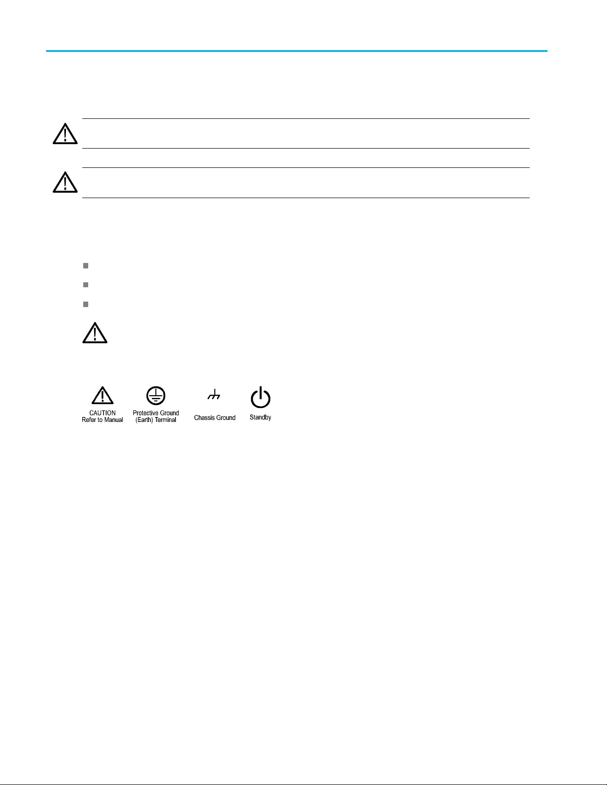
When this symbol is marked on the product, be sure to consult the manual to find out the nature o f the
potential hazards and any actions which have to be taken to avoid them. (This symbol may also be used to
refer the user to ratings
in the manual.)
The following symbol(s) may appear on the product:
viii TBS2000 Series User Manual
Page 15

Preface
This manual describes the installation and operation of the following oscilloscopes:
TBS2072 TBS2102 TBS2074 TBS2104
Key features
This oscilloscope can help you verify, debug, and characterize electronic designs. Key features include:
100 MHz and 70 MHz bandwidths
2 channel and 4 channel models
TekVP I®Versatile Probe Interface supports active voltage and current probes for automatic scaling and units
Large 9 inch (228 mm) WVGA wide-screen color display
Sample rates up to 1 GS/s (1 channel on 2-channel instruments; 2 channels on 4-channel instruments)
Up to 20 million points record length on every channel
Preface
10,000 waveforms/second capture rate
More than 32 automated measurements
Runt and pulse width triggers
FFT analysis for waveform spectrum analysis
Wi-Fi (with optional TEKUSBWIFI dongle) and Ethernet for remote operation and programming
Embedded LXI Web site, accessed by typing instrument IP address into a Web browser, provides remote UI control and
SCPI co
USB 2.0
drives; i nstalling firmware updates; and loading waveforms and settings from saved fi les
USB 2.0 Device port for direct PC control of the oscilloscope using TekVISA connectivity, and other remote connectivity
tools that support USBTMC
Scope Intro provides a built-in overview of oscilloscope concepts and an introduction to the TBS2000 controls and
feat
Help
settings
Courseware function provides on-oscilloscope teaching instruction, with hundreds of courses available on the Tektronix
Education Web page and the ability to easily create courses specific to your education needs
mmand support
Host ports for quick and easy storage of screen images, instrument settings, and waveforms to USB flash
ures
Everywhere displays graphics and short text descriptions when you access the menus for most oscilloscope
TBS2000 Series User Manual ix
Page 16

Preface
Terms in this m anual
These terms may appear in this manual:
WARNING. Warning statements identify conditions or practices that could r esult in injury or loss of life.
CAUTION. Caution statements identify conditions or practices that could result in damage to this product or other property.
Symbols and terms on the product
These terms may appear on the product:
DANGER indicates an injury hazard immediately accessible as you read the m arking.
WARNING indicates an injury hazard not immediately accessible as you read the marking.
CAUTION indicates a hazard to property including the product.
When this symbol is marked on the product, be sure to consult the manual to find out the nature o f the
potential hazards and any actions which have to be taken to avoid them. (This symbol may also be used to
refer the user to ratings
in the manual.)
The following symbol(s) may appear on the product:
x TBS2000 Series User Manual
Page 17

Conventions used in this manual
The following icons are used throughout this manual.
Preface
Sequence Step
Front panel power
Connect power
Network
USB
TBS2000 Series User Manual xi
Page 18

Preface
xii TBS2000 Series User M anual
Page 19

Installation
Before installation
Unpack the oscilloscope and check that you received all items listed as standard accessories. The following pages list
recommended accessories and probes, oscilloscope options, and upgrades. Check the Tektronix Web site (www.tek.com)
for the most current information.
Standard accessories
Accessory Description
TBS2000 Series Oscilloscopes Safety and
Installation Instructions
TBS2000 Series Oscilloscopes
Documentation Browser CD
Calibration certificate documenting
traceability to national metrology institute(s),
and ISO9001 quality system registration.
Probes (all models)
Five year warranty
Power cord
Printed safety and installation information. The
instructions are translated into 10 languages.
Electronic versions of documents, including
the User Manual, Programmer Manual and
Technical References.
2 Ch Models: Two T PP0100 100 MHz, 10X
passive voltage probes with 10 M input
resistance.
4 Ch Models: Four TPP0100 100 MHz, 10X
passive voltage probes with 10 M input
resistance.
For details, refer to the warranty at the front
of this manual
North America (Option A0)
Universal Euro (Option A1)
United Kingdom (Option A2)
Australia (Option A3)
Switzerland (Option A5)
Japan (Option A6)
China (Option A10)
India (Option A11)
Brazil (Option A12)
No power cord or AC adapter (Option A99)
Installation
Tektronix part
number
071-3556-xx
063-4568‑xx
––
TPP0100
––
161-0348-xx
161-0343-xx
161-0344-xx
161-0346-xx
161-0347-xx
161-0342-xx
161-0341-xx
161-0349-xx
161-0356-xx
––
TBS2000 Series User Manual 1
Page 20

Installation
Standard accessories (cont.)
Tektronix part
Accessory Description
Front-panel overlays are provided with the
ordered language option.
French (Option L1)
Italian (Option L2)
German (Option L3)
Spanish (Option L4)
Japanese (Option L5)
Portuguese (Option L6)
Simplified Chinese (Option L7)
Traditional Chinese (Option L8)
Korean (Option L9)
Russian (Option L10)
number
Optional accessories
Accessory Description Tektronix part number
TEKUSBWIFI The USB module adds Wi-Fi connectivity for remote
programmability and control
TekV P I®probes that work with
TBS2000 Series oscilloscopes
50 BNC adapter Connect 50 cables to the oscilloscope
Deskew pulse generator Deskew pulse generator and signal source with
Power measurement deskew and
calibration fixture
TEK-USB-488 Adapter GPIB to USB Adapter TEK-USB-488
Soft transit case
Hard transit case (requires use of
soft transit cas e)
Visit theOscilloscope Probe and Accessory Selector
Tool on the Tektronix Web site at www.tek.com
TekVPI oscilloscope interface
Converts TEK-DPG pulse generator output into a
series of test point connections
Two-channel oscilloscopes
Four-channel oscilloscopes
Two- and four-channel oscilloscopes HCTEK4321
TEKUSBWIFI
013-0227-00
TEK-DPG
067-1686-00
ACD2000
ACD4000B
The TBS2000 series oscilloscopes work with multiple optional probes. (See page 11, Connecting probes to the oscilloscope.)
Check the Tektronix Web site (www.tek.com) for the most current information.
2 TBS2000 Series User Manual
Page 21

Installation
Related documentation
Accessory Description Tektronix part number
TBS2000 Series Oscilloscopes User Manual
TBS2000 Series Oscilloscopes Specifications
and Performance Verification Manual
TBS2000 Series Oscilloscopes Programmer
l
Manua
000 Series Oscilloscopes Service
TBS2
Manual
English 077-1147-xx
French 077-1264-xx
German
Italian 077-1266-xx
Spanish
Portuguese 077-1268-xx
Korean 077-1269-x
Japanese 077-1270-xx
Simple Chinese
Traditional Chinese
Russian 077-1273-xx
Describes the oscilloscope specifications
and performance verification procedure.
le electronically on the Documentation
Availab
Browser C D or for download from
www.tek.com/downloads. English only.
Describes commands for remote control of
cilloscope. Available electronically
the os
on the Documentation Browser CD or for
download from www.tek.com/manuals.
sh only.
Engli
ice information. Available electronically
Serv
on the Documentation Browser CD or for
download from www.tek.com/downloads.
ish only
Engl
077-1265-xx
077-1267-xx
077-1271-xx
077-1272-xx
8-xx
077-114
077-1149-xx
077-1150-xx
x
TBS2000 Series User Manual 3
Page 22

Operating requi
rements
Operating req
Make sure to operate the instrument within the following environmental and power requirements.
uirements
Environment requirements
Characteristic Description
Operating temperature 0 °C to +50 °C, with 5 °C/minute maximum gradient, noncondensing, up to 3000 meter
Operating humidity 5% to 95% relative humidity (% RH) up to +30 °C
Operating altitude Up to 3000 meters (9842 feet)
Power requirements
Characteristic Description
Power source voltage
Power source frequency 50/60 Hz over entire source voltage range
Power consumption All models: 80 W maximum
altitude
5% to 60% RH above +30 °C up to +50 °C, noncondensing
100 V
400 Hz (360 Hz to 440 Hz) for 115 V
– 240 VAC±10% RMS, single phase
AC
AC
(100 VAC– 132 VAC) RMS source voltage range
CAUTION. A ground connection through the power cord grounding conductor is essential for safe operation.
4 TBS2000 Series User Manual
Page 23

Getting acquain
ted with the oscilloscope
Getting acqua
This section shows you how to power on the oscilloscope, and uses a hands-on approach to introduce you to key
oscilloscope functions, using the menu system, and verifying that the oscilloscope is operating correctly.
inted with the oscilloscope
Powering on and off the oscilloscope
Grounding the oscilloscope is necessary for safety and to take accurate measurements. The oscilloscope must share the
same ground
power cord into an outlet grounded to earth ground.
To connect the power cord and power on the oscilloscope:
as any circuits that you are testing. You connect the oscilloscope to ground by plugging the three-pronged
wer off the oscilloscope and remove the power cord:
To po
TBS2000 Series User Manual 5
Page 24

Getting acquain
ted with the oscilloscope
NOTE. The current instrument settings are stored in nonvolatile memory when you power off the oscilloscope. The
oscilloscope restores the settings when you power on.
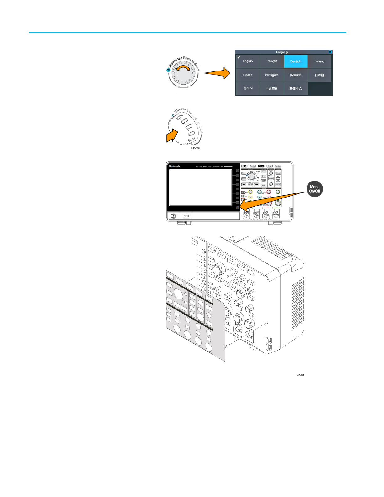
Changing the user interface language
You can change the language used for the oscilloscope on-screen display, measurements, readouts, and menus to one of
11 languages.
The following steps show how to change the user interface language. These steps also introduce you to the oscilloscope
menu system.
1. Push the Utility front-panel button. The
oscilloscope displays a side menu on the
right side of the screen.
6 TBS2000 Series User Manual
Page 25

Getting acquain
ted with the oscilloscope
2. Push the Langua
The oscillosc
menu.
YouwillusetheMu ltip urpose knob
to select and
following text describes how the
Multipurpose knob works.
The Multipurpose knob lets you interact with
on-screen
boxes.
A blue-colored M icon on a menu, message,
or dialog
the Multipurpose knob to select and click
values in that item.
The turn arrow indicator, located below the
knob, turns green when you can use the
knob to m
menu or dialog box.
menus, messages, and dialog
box label means that you can use
ake selections or enter values in a
ge side-menu button.
ope opens the Language
click menu items. The
The knob has two functions:
Select function, where you turn the
knob to select (highlight) a menu
item. Selecting a menu item does
not execute (run) that function.
Click function, where you push the
knob to either run the selected menu
item or enable a field in that menu
item to enter numbers or select
values.
TBS2000 Series User Manual 7
Page 26
Getting acquain
ted with the oscilloscope
3. Turn the Multip
language.
4. Click (push) the Multipurpose knob
to enter the highlighted language.
The selected language takes effect
immediately.
5. Push the Menu On/Off buttontoclose
the Utility menu.
urpose knob to select a
6. If you load a language other than English,
install the plastic overlay on the front
panel to provide labels in that language.
Fold the overlay tabs. Push the overlay
over the knobs until the knob hole tabs
click over the bottom edges of the knobs.
Insert the overlay tabs into the small
slots.
If you are changing from a non English
language to English, remove the
front-panel language overlay.
8 TBS2000 Series User Manual
Page 27
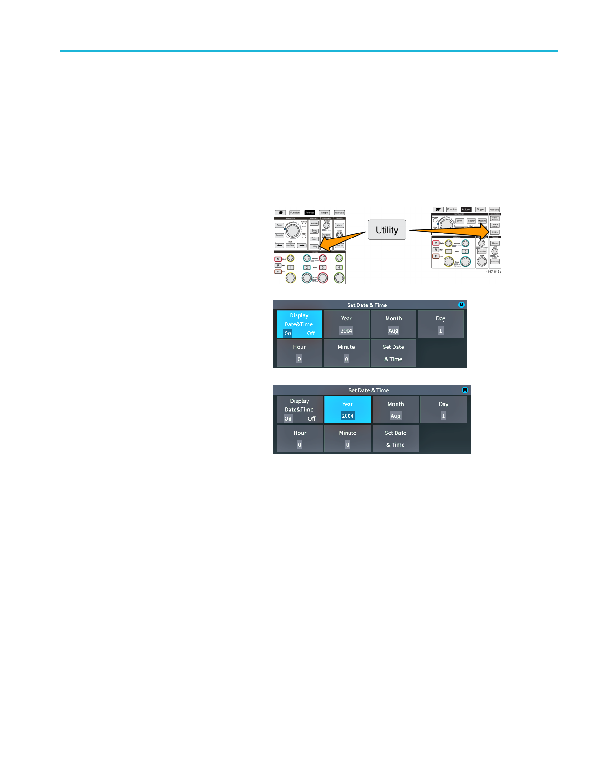
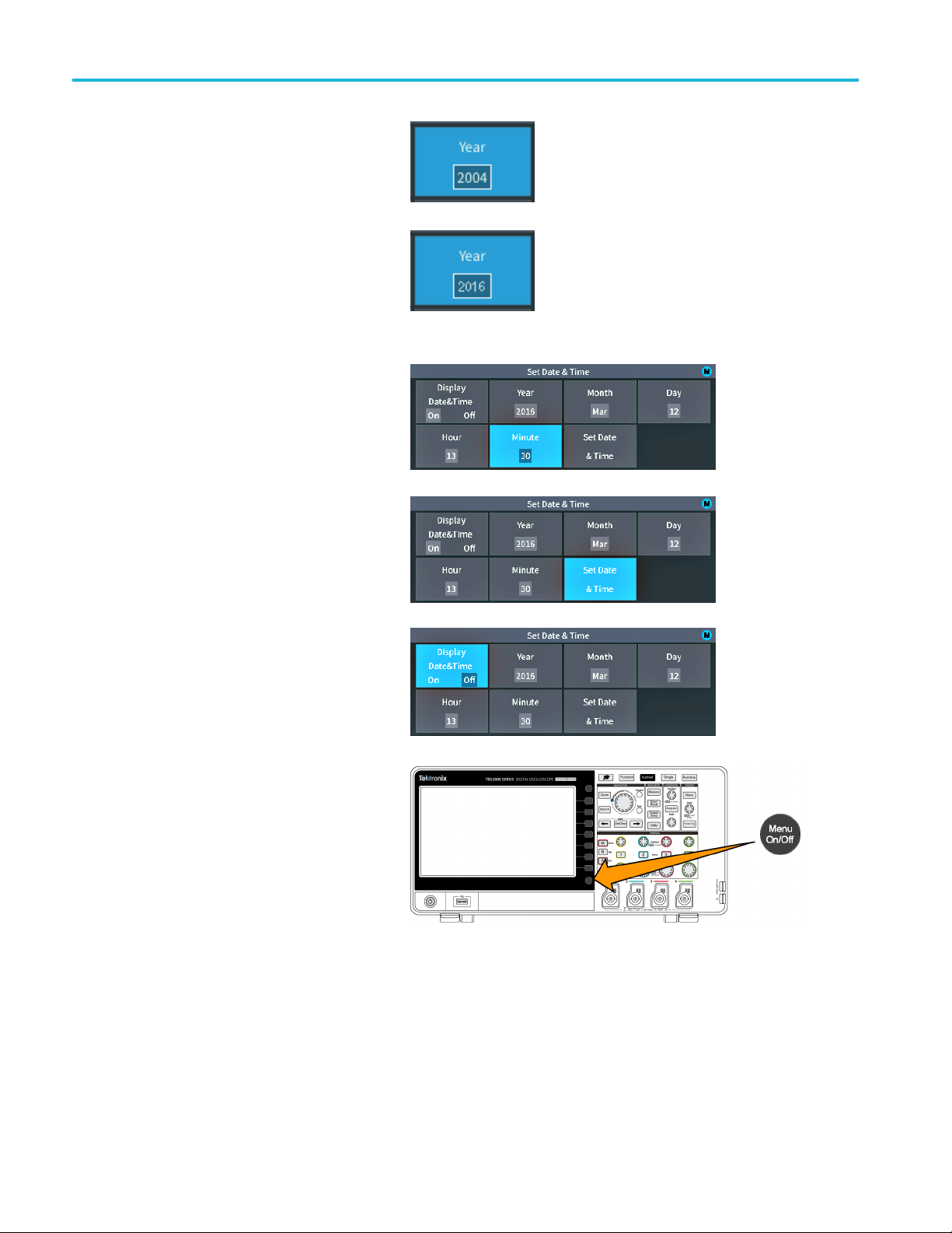
Changing the date and time
Set the current data and time so that files that you save are marked with the correct date and time. The date and time are
shown in the lower-right corner of the screen. Time is shown using a 24-hour clock.
NOTE. The clock does not automatically adjust for seasonal time changes. The calendar does adjust for leap years.
The following steps show how to set the oscilloscope clock with the current date and time. These steps also introduce
you to more functions of the menu system.
1. Push Utility front-panel button.
Getting acquain
ted with the oscilloscope
2. Push Set D
button. The oscilloscope shows the Set
Date & Time menu.
3. Turn the Mu ltipurpose knob to select
the Yea
ate & Time side-menu
r field.
TBS2000 Series User Manual 9
Page 28
Getting acquain
4. Click the Multipurpose knob to enable
5. Turn the Multipurpose knob to change
6. Repeat steps 3 – 5 to select and change
7. When you have finished making all date
ted with the oscilloscope
setting the year value. A white box is
drawn around t
that you can use the Multipurpose knob
to change that value.
the year value in the field.
When the val
Multipurpose knob. This enters the
number and returns the knob to menu
select mode
the remain
(Month, Day, Hour, Minute).
and time changes, turn the Multipurpose
knob to s
click the knob to enter the date/time
settings into the oscilloscope.
he number field, indicating
ue is correct, click the
.
ing date and time settings
elect Set Date & Time, then
8. To turn off displaying the date and time,
Display Date & Time and click the
select
Multipurpose knob to toggle On or Off.
9. Push the Menu On/Off buttontoclose
the Utility side menu.
The new date and time are shown in the
lower-right corner of the screen.
10 TBS2000 Series User Manual
Page 29

Connecting probes to the oscilloscope
You must connect probes or cables to an oscilloscope before you can display a waveform and take measurements. The
following text describes how to connect probes to the oscilloscope.
1. BNC probes or cables: Push the BNC
probe or cable on to the connector so that
the connector pins align with the slots,
then turn the BNC connector clockwise
to lock. The probes that ship with the
oscilloscope are BNC connector probes.
NOTE. If you connect a cable to the channel
input, you will need an impedance matching
adapter to convert the cable impedance
(typically 50 Ω, but it depends on the
cable) to work with the 1 MΩ channel input
impedance.
Getting acquain
ted with the oscilloscope
2. Tektronix Versatile Probe Interface (TekVPI®): Push the probe base into the channel connector until the probe base
connector clicks. To remove, push and hold the button on the probe base and pull the probe from the connector.
®
TekVPI
(10X, 1X, X10, and so on).
probes automatically set the oscilloscope probe parameters such as type (voltage, current) and attenuation
Supported probe types
For more information on the many probes available for use with TBS2000 Series oscilloscopes, visit the Oscilloscope Probe
and Accessory Selector tool on the Tektronix Web site (www.tek.com).
cing electrostatic damage while taking measuremens
Redu
Static electricity that builds up on your body
can damage static-sensitive components.
uareworkingwithstatic-sensitive
If yo
components, ground yourself when using
probes. Wearing a grounding strap safely
ds static charges on your body to earth
sen
ground.
Connect the grounding strap to the
cilloscope ground, or to the same ground
os
circuit that the oscilloscope is connected to.
TBS2000 Series User Manual 11
Page 30
Getting acquain
ted with the oscilloscope
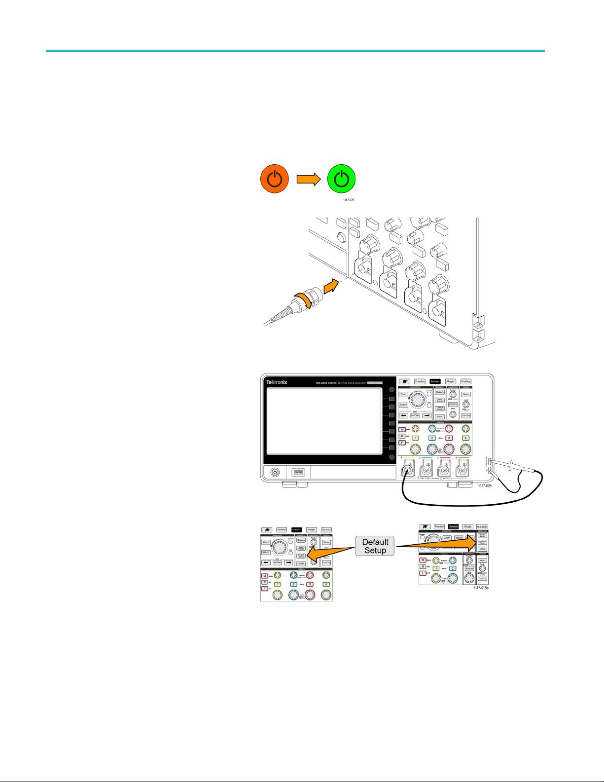
Doing a functional check
Perform this quick functional check to verify that your oscilloscope is operating correctly.
1. Connect the oscilloscope power cable
as described in Powering On the
Oscilloscope. (See page 5.)
2. Power on the oscilloscope.
3. Connect a probe that came with the
oscilloscope to channel 1.
4. Connec
5. Push Default Setup. Default Setup
t the probe tip and ground lead
to the PROBE COMP connectors on
the oscilloscope front panel. The probe
nectstothe5Vconnector, and
tip con
the ground clip connects to the ground
connector.
returns the oscilloscope settings to
factory default values. (See page 113,
The default oscilloscope settings (Default
Setup).)
12 TBS2000 Series User Manual
Page 31

6. Push Autoset.
The screen displays a square wave.
Getting acquain
ted with the oscilloscope
If the displayed square wave tops are
not flat, perform the procedures to
compensate the probe high frequency
response. You can compensate the
probe after completing this functional
check. (See page 15.)
7. Push Measure to open the
Measurement Selection menu.
TBS2000 Series User Manual 13
Page 32

Getting acquain
ted with the oscilloscope
8. Turn the Multip
Snapshot.
9. Click the Multipurpose knob to show the
Snapshot screen.(See page 48, Ta k ing
a measurements snapshot.)
Verify that the Frequency value is
~1 kHz and the Period valueis~1ms,
respectively.
10. Push the Menu On/Off button to
close the
Menu On/Off button again to close the
Measurement screen.
urpose knob to select
Snapshot screen. Push the
What is Autoset?
The functional check used the Autoset button to display a stable waveform. Autoset automatically adjusts the osc illoscope
acquisition, horizontal, trigger, and vertical controls to display five or six waveform cycles for an active (displayed) channel.
This powerful function can save you time when you need to view an unknown signal. See the Autoset topic for more
information.(See page 38, Using Autoset.)
14 TBS2000 Series User Manual
Page 33

Compensating a passive voltage probe
Probe compensation adjusts a passive (nonamplified) voltage probe for the most accurate high-frequency response. The
oscilloscope has a 1 kHz square wave source for compensating the probe. Because a square wave contains a s ignifi cant
number of harmonics (multiples of the fundamental frequency), i t is an ideal signal source for adjusting the high frequency
response of a probe.
A rounded leading edge on the square wave means that the high frequency response of the probe is too low. A spike on the
leading edge means that the high frequency response is too high and must be reduced. A square leading edge means that
the frequency response is correct for the probe.
Whenever you attach a passive voltage probe for the first time to any input channel, or change a passive probe from one
channel to another, you must compensate the probe to match it to that input channel.
To properly compensate your passive probe:
1. Power on the oscilloscope.
2. Connect the probe that shipped with the
instrument, or other passive probe, to an
oscilloscope channel.
Getting acquain
ted with the oscilloscope
3. Connect the probe tip and ground lead
to the PROBE COMP connectors on the
loscope. The probe tip connects to
oscil
the 5 V connector, and the ground clip
connects to the ground connector.
TBS2000 Series User Manual 15
Page 34

Getting acquain
4. Push Default Setup.
5. Push the Vertical Menu button for the
6. Push Autoset.
ted with the oscilloscope
channel to which the probe is connected,
to display that channel.
The screen displays a square wave.
16 TBS2000 Series User Manual
Page 35

7. Check the shape of the displayed
waveform to determine if the probe
needs adjuste
a square leading edge and a flat top
and bottom, the probe does not need
adjusted.
d. If the waveform has
Getting acquain
ted with the oscilloscope
If the wavef
or has a spike, you need to adjust the
probe compensation.
8. Use the probe adjustment tool to adjust
the probe to show a flat top and bottom to
the w aveform. Remove the adjustment
tool before looking at the waveform.
Repeat until waveform top and bottom
are flat.
9. Repeat this procedure from step 5 for
each probe connected to each c hannel.
You must also run this procedure if
you move a probe from one channel to
another.
orm leading edge is rounded
Probes and ground leads tip
When taking a real measurement, use the
shortest possible ground lead and signal
path to minimize probe-induced ringing and
distortion on the measured signal.
Signal with a short length ground lead
TBS2000 Series User Manual 17
Signal with a long ground lead
Page 36

Getting acquain
ted with the oscilloscope
Signal path compensation (SPC)
Signal Path Compensation (SPC) corrects for DC level inaccuracies in the internal signal path caused by temperature
variations and/or long-term signal path drift. You should run the SPC whenever the ambient (room) temperature has changed
by more than 10 °C, or once a week if you use vertical scale settings of 5 mV per division or less. Failure to run a SPC may
result in the oscilloscope not meeting warranted performance levels at those volts per division settings.
To compensate the signal path for all channels:
1. Power on and warm up the oscilloscope for
at least 20 minutes.
2. IMPO RTANT: Remove all input signals
(probes and cables) from channel inputs
and the Aux Out connector on the back of
the oscilloscope.
3. Push Utility.
4. Push the -More- Page 1/2 side-menu button.
5. Push th
6. Turn the Multipurpose knob to select Signal Path, then click the Multipurpose knob to start the SPC process.
7. Push the Compensate Signal Paths side-menu button to start the process.
8. Push
9. Reco
e Calibration side-menu button.
illoscope shows a Signal Path Compensation information message.
The osc
reen shows rotating dots while the S PC is run. The oscilloscope displays a message when the SPC is complete.
The sc
SPC c an take several minutes to run, so wait until the oscilloscope shows a message that SPC is completed.
Menu Off to remove the message and menus.
nnect probes to the oscilloscope.
18 TBS2000 Series User Manual
Page 37
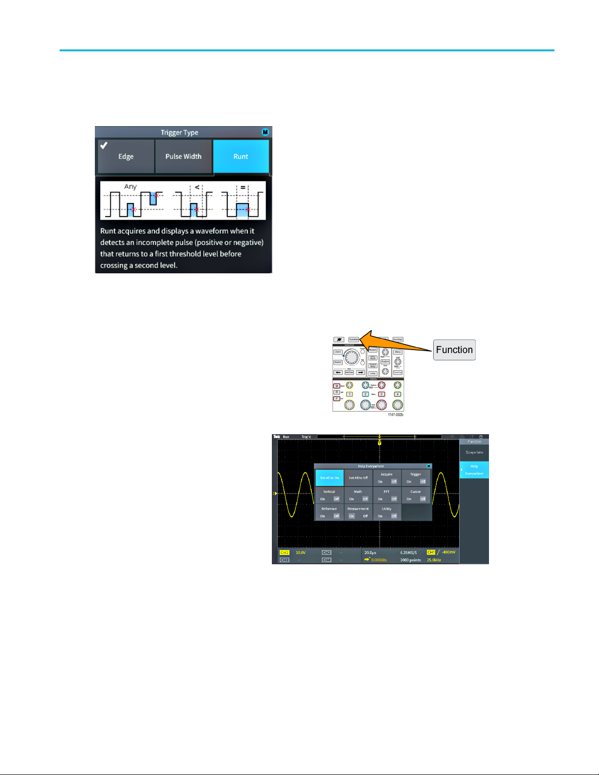
Getting on-screen help for settings: Help Everywhere
Help Everywhere is a mode that displays graphics and short text descriptions when you access the menus for most
oscilloscope settings. This is very useful for when you are first learning the functions of oscilloscope controls.
You can enable Help Everywhere content for all supported settings, or enable it for specific function groups, such as
Trigger controls, Vertical controls, and so on.
Getting acquain
ted with the oscilloscope
1. Push the Function front-panel button.
2. Push th
e Help Everywhere side-menu
button to display the menu. All Help
Everywhere content is set to Off by
lt except for the Measurement
defau
category, which is On.
TBS2000 Series User Manual 19
Page 38
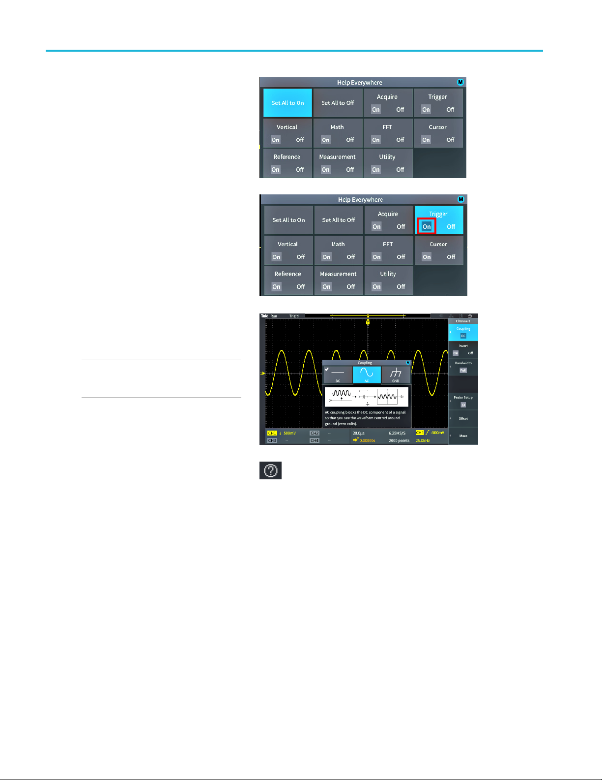
Getting acquain
ted with the oscilloscope
3. To t ur n all Help
or off, use the Multipurpose knob to
select Set All to On or Set All to Off,
then click the
4. To set individual menu categories
to show Help Everywhere,usethe
Multipurpo
then click the knob to toggle that
selection On or Off.
ThenexttimeyouaccessaHelp
Everywhere-supported menu setting,
the oscilloscope displays the help for
that item.
Everywhere content on
knob.
se knob to select a category,
NOTE. You may need to turn the
Multipurpose knob and select another menu
item to show the Help Everywhere content.
When any Help Everywhere content is
enabled, the Help Everywhere icon is
highlighted (in upper right corner of screen).
20 TBS2000 Series User Manual
Page 39

The Scope Intro function
The Scope Intro function provides a brief history of oscilloscopes, some basic oscilloscope concepts, and an overview of the
oscilloscope features and controls.
You can view any topic in any order.
1. Push the Function front-panel button.
2. Push the Scope Intro side-menu button.
3. Use the Multipurpose knob to select and click a topic heading.
4. Use the Multipurpo se knob to select and click a topic to read.
5. Push the relevant side-menu button to return to the menu for the subject category, and select and click the next topic
to view.
Getting acquain
ted with the oscilloscope
6. When you
menu, and select a new category to read.
7. Push the Menu On/Off button to close the Scope Intro mode.
NOTE. The Scope Intro function does not remember which topics you have read.
are done viewing the topics for that category, push the Scope Intro side-menu button to return to the main
TBS2000 Series User Manual 21
Page 40

Sampling oscill
oscope concepts
Sampling osci
Read this section if you are a new oscilloscope user, or are new to using a digital oscilloscope.
lloscope concepts
Sampling and acquisition concepts
Before the oscilloscope can display or measure a signal, it must be sampled. Sam pling is the process of measuring the
input signal amplitude value a t regular intervals (called the sampling rate, in samples per second), converting the sampled
levels into
the digitized values in the waveform record to create, display, and measure waveforms. Each oscilloscope channel has
its own waveform record memory storage.
TBS2000 Series oscilloscopes use real-time sampling. In real-time sampling, the oscilloscope samples and digitizes all
of the sampled points at one time, in sequence, stores the sampled data in memory, and then repeats the sampling and
storage process.
You u se the Horizontal Scale knob to change the sample rate (samples per second). The oscilloscope automatically sets
the sample rate so that there are more than enough samples to accurately capture the signal information. The sample rate is
shown on the screen at all times in the horizontal position/scale readout. See item 11 in The graphical user elements section.
digital data, and storing the sampled values in memory to create a waveform record. The oscilloscope uses
NOTE. The maximum sample rate of 1 GS/s is only available when one channel per channel pair is active ( channel 1, 2
pair or channel 3, 4 pair).
For two-channel models, only one channel (either channel 1 or 2) can sample at 1 Gs/s. If channel 1 and 2 are both
active, then the maximum sample rate changes to 500 MS/s.
On four-channel models, only two channels can sample at 1 GS/s (one channel from each pair). So if channel 1 or 2, and
channel 3 or 4, are active, the maximum sample rate is available. Turning on a 3rd channel (in either pair) changes the
maximum sampling rate to 500 MS/s.
You can set the waveform record length (number of sample points in the waveform record) from 2000 points to 20 million
points (20M). A longer (larger) waveform record is useful to capture several waveform cycles to search for a waveform of
interest, or to capture a great deal of detail for just a few waveform cycles and then use the Zoom function to search
the waveform for areas of interest.
22 TBS2000 Series User Manual
Page 41

Sampling oscill
Each time the oscilloscope fills the waveform record is called a waveform acquisition,oracquisition for short. Acquisitions
happen up to 10,
record for that channel.
A waveform record is further divided into acquisition intervals, which are equally sized groups of samples. Acquisition
intervals let the oscilloscope perform calculations to analyze and display data such as the minimum and maximum data
values per int
by the acquisition mode.
000 times a second, for all channels. Each acquisition stores new sample data into the same waveform
erval, or the average signal value per interval. How the values in the a cquisition interval are used is set
oscope concepts
Acquisition mode concepts
The acquisition mode sets how the oscilloscope uses the sampled data points in each acquisition interval to create and
display a waveform. You can set the acquisition mode to one of the following modes.
Sample mode retains and uses the first
sampled point from each acquisition interval
to create the displayed waveform. This is the
default mode.
Peak Detect mode uses the highest and
lowest of all the samples contained in two
consecutive acquisition intervals. Use this
mode to help detect short rapid transitions in
a waveform.Peak Detect is not available at
faster time per division settings.
Hi Res mode oversamples lower-frequency
signals and calculates the average of all the
samples for each acquisition interval. Use
Hi Res mode to provide higher-resolution
(16-bit) sample points for lower-frequency
waveforms.
Average mode calculates and displays the
average value for each sample point over a
user-specified number of acquisitions. Use
Average mode to reduce random noise.
TBS2000 Series User Manual 23
Page 42

Sampling oscill
oscope concepts
Trigger concepts
The oscilloscope uses the data in the waveform record to construct and display a waveform on the oscilloscope screen.
However, as the oscilloscope is constantly acquiring sample s into the waveform record, each waveform record starts a t a
random point of the input signal. This means that the waveform record sample values are constantly changing, which results
in a displayed waveform that is unstable or jittering. An unstable waveform cannot be accurately measured, making this
display useless except for very broad measurements (type of signal, approximate peak to peak signal amplitude).
Untriggered display
What is needed is a way to set the oscilloscope to detect, or trigger on, the same signal condition or state on the input signal
for each
the same sample time location in the waveform record.
waveform acquisition, and store the samples in the waveform record such that the same signal condition is at
A trigger sets when the oscilloscope detects a defined waveform condition, such as at a specified signal voltage level on
the rising edge of the s ignal. The oscilloscope uses that trigger condition to store the waveform samples in the waveform
so that the signal sample point that meets the trigger condition is at the same location in the waveform record. When
record
displayed, the waveform record for each acquisition shows the waveform at the same trigger point, resulting in a stable
waveform on the screen.
Triggered display
24 TBS2000 Series User Manual
Page 43

Sampling oscill
Understanding and using triggers is probably the most important skill needed to quickly display and analyze waveforms.
A trigger condi
level to a high level (positive slope). A trigger condition can also be very specific, such as when the signal level is falling
and the width of a single pulse of the signal is less than a specified time period.
The trigger point in a waveform record also sets the zero time-reference point in a waveform record. By default, the trigger
point in a wave
waveform before the trigger condition (pretrigger), and the other half shows the waveform after the trigger condition
(post-trigger).
Pretrigger data can help you troubleshoot signal problems. For example, to find the cause of an unwanted glitch in your test
circuit, tri
uncover information that helps you find the source of the glitch.
tion can be as simple as when the signal passes through a specified voltage level when going from a low
form record is in the center of the waveform record. This means that half of the record shows the signal
gger on the glitch signal and look at the pretrigger waveform. By analyzing what happens before the glitch, you may
oscope concepts
Trigger slope and level concepts
The oscilloscope must detect both the slope and level conditions before it can trigger and display a stable waveform.
The minimum trigger conditions needed to display a stable waveform are the signal slope and threshold level. The
slope sets the oscilloscope to find the trigger point on the rising or the falling edge of a signal. The level sets where on
that edge the trigger point occurs.
The trigger Slope sets the oscilloscope to
find the trigger event on the rising or the
falling edge of a signal.
The trigger threshold Level (or just level) is
the signal amplitude value on a slope that
must occur for the oscilloscope to trigger on
a signal.
A runt trigger needs two thresholds to define
the two levels that a signal must pass through
to be considered a valid (nonrunt) signal.
The arrow at the far right of the screen marks
the threshold level(s) for that signal.
Turning the Trigger Level knob changes
the threshold level and momentarily displays
a long horizontal line (or two lines for a
runt trigger) across the waveform to show
the trigger level(s) in relation to the overall
waveform.
TBS2000 Series User Manual 25
Page 44

Sampling oscill
Available trigger types
The oscilloscope lets you trigger on several signal conditions:
Trigger type Trigger conditions
Edge Edge triggers are the simplest and most commonly used trigger
oscope concepts
type. An edge trigger event occurs when the trigger source passes
through a specified voltage threshold (trigger level) when the signal
is transitioning in the specified slope (rising or falling).
You can trigger on a rising or falling edge, as defined by the slope
control.
Pulse
Width
Runt
You can trigger on pulses that are less than, greater than, equal to,
or not equal to a specified time period. You can trigger on positive
or negative pulses.
Pulse width triggers are primarily used to analyze digital signals.
A runt pulse is a pulse that crosses one threshold but fails to cross
a second threshold before recrossing the first. Therefore, a runt
trigger needs two thresholds to define the two levels that a signal
must pass through to be considered a valid (nonrunt) signal.
You can trigger on any positive or negative (or either) runt signal.
You can also trigger on runt signals with pulse widths that are less
than, greater than, equal to, or not equal to a specified width.
Runt triggers are primarily used to analyze digital signals.
Trigger coupling
Trigger coupling sets what part of the input signal is used by the trigger circuit. Trigger coupling choices are DC, LF Reject,
HF Reject, and Noise Reject.
DC Coupling passes the trigger signal to the trigger circuit with no filtering. The scope may trigger on false events if
gnal is noisy.
the si
ject blocks signals above 85 kHz from the trigger circuit. This reduces false triggering on high-frequency noise
HF Re
when measuring lower-frequency signals.
LF Reject blocks signals below 65 kHz from the trigger circuit. This reduces false triggering from low frequency noise
when measuring higher-frequency signals.
Noise Reject reduces the trigger circuit input sensitivity. This reduces false triggering when measuring signals with
her levels of noise.
hig
26 TBS2000 Series User Manual
Page 45

Sampling oscill
oscope concepts
Trigger modes
The Trigger Mode sets how the oscilloscope behaves in the absence or presence of a trigger. Trigger mode also enables
the trigger holdoff function.
Auto (Untriggered Roll) trigger mode. The Auto (Untriggered Roll) mode sets the oscilloscope to acquire a
waveform even if a trigger does not occur. Auto mode uses a timer that starts when the acquisition is started, and the
pretrigger i
trigger. The length of time it waits for a trigger event depends on the time base setting (Horizontal Scale).
Auto mode, when forcing triggers in the absence of valid triggering events, does not synchronize the waveform on the
display. The waveform will appear to roll across the screen. If valid triggers occur, the display will become stable.
Normal trigger mode. Normal mode sets the oscilloscope to acquire a waveform only when a trigger condition occurs.
If no trigger occurs, the last waveform record acquired remains on the display. If no last waveform exists, no waveform
is displayed.
Holdoff trigger mode. The Holdoff trigger mode lets you set a time period during which the oscilloscope ignores trigger
events. For example, to trigger on the first pulse of a pulse burst, you would set the trigger conditions to trigger on a positive
edge, and
bust occurs. Using Holdoff in this case prevents the oscilloscope from triggering on any positive signal edge.
nformation is obtained. If a trigger event is not detected before the timer times out, the oscilloscope forces a
set the holdoff value so that the trigger is disabled for a period of time after the trigger event but before the next
Use Set Holdoff to minimum to set the holdoff value to the minimum value.
NOTE. The trigger mode does not set the trigger conditions; those are set with the trigger Type controls. (See page 26,
Available trigger types.)
Trigger delay (acquisition mode)
In normal acquisition modes, the trigger point is located at the center of the waveform record, and is positioned at the
ter-screen expansion point so that horizontal scale changes are centered around the trigger point. The Delay function
cen
in the Acquire menu disconnects the trigger point from the center-screen expansion point. This feature lets you use the
Horizontal Position knob to reposition (delay) the trigger point from the expansion point by a specified amount.
ThemostcommonuseforDelay is to acquire and display waveform detail that is separated after the trigger event by a
nificant interval of time. For example, you can trigger on a pulse that occurs once every 10 ms and then use Delay to look
sig
at the s ignal characteristics that occur 6 ms after the trigger point.
TBS2000 Series User Manual 27
Page 46

Setting channel
input parameters
Setting chann
Use the vertical Menu buttons to select waveforms to display or open menus and submenus with which to set input
parameters for each channel.
Each channel’s settings are independent of every other channel.
el input parameters
Setting input signal coupling
Input signal coupling sets how the input signal is pas sed to the oscilloscope sampling circuit.
1. Push the Ver
channel input that you want to set.
2. Push the Coupling side-menu button.
3. Use the Multipurpose knob to select and click the coupling type:
DC coupling passes both AC and DC signal components.
AC coup
tical Menu button for the
ling blocks the DC component and passes only the AC signal.
Inver
Ground internally disconnects the input signal and connects that channel to a ground reference. This is a fast way to
ine where the ground level is for signals that have a DC component or offset.
determ
ting the input signal
Use this procedure to invert (flip vertically) the signal. A typical reason to invert a signal is to use the inverted signal to
create a math waveform.
1. Push the Vertical Menu button for the
channel input that you want to set.
2. Push the Invert side-menu button to toggle between Off for normal operation and On to invert the polarity of the signal
in the preamplifier.
28 TBS2000 Series User Manual
Page 47

Setting the oscilloscope bandwidth
Use this procedure to set the oscilloscope bandwidth. Bandwidth is the maximum frequency that an oscilloscope can
accurately display and measure. The oscilloscope gradually attenuates (reduces) the signal level of frequencies that are
higher than the bandwidth. This means that although you can display signals that are above the bandwidth limit, their
amplitude values and other characteristics are not guaranteed to be accurate.
1. Push the Vertical Menu button for the
channel input that you want to set.
2. Push the Bandwidth side-menu button.
3. Use the Multipurpose knob to select and click the bandwidth setting.
Full sets the bandwidth to the maximum bandwidth of which the oscilloscope is capable.
20 MHz sets the bandwidth to 20 MHz.
Other bandwidth choices may be shown on the menu depending on the connected probe.
Setting channel
input parameters
Setting the probe type (voltage or current)
The Probe Type submenu sets the type for probe that is connected to the oscilloscope. The default probe type is Vo ltage .
er valid probe type is current. Probes that have a TekProbe II or TekVPI interface automatically set the probe type
The oth
and related parameters when you plug them into the oscilloscope.
1. Push the Vertical Menu button for the
el input that you want to set.
chann
2. Push the Probe Setup side menu to display the Probe Setup submenu.
3. Use the Multipurpose knob to select and click Probe Type submenu item.
4. Select and click the probe type (Voltage or Current).
TBS2000 Series User Manual 29
Page 48

Setting channel
input parameters
Setting the probe attenuation factor
Attenuation is the amount that the probe reduces or amplifies the input signal amplitude before sending it to the oscilloscope
input. The Attenuation submenu sets the probe attenuation factor for probes that do not have the TekProbe II or TekVPI
interface. The default attenuation is 10x.
1. Push the Vertical Menu button for the
channel input that you want to set.
2. Push the Probe Setup side menu to display the Probe Setup submenu.
3. Use the Multipurpose knob to select and click the Attenuation submenu item.
4. Use the Multipurpose knob to select and change the a ttenuation factor.
Quickly setting the probe attenuation to 1X or 10X
The Set T
1. Push the Vertical Menu button for the
2. Push t
3. Use the Multipurpose knob to highlight either Set To 1X or Set To 10X submenu item. Then click the multipurpose
o1Xand Set To 10X submenu items let you quickly set the probe attenuation to either 1X or 10X.
channel input that you want to set.
he Probe Setup side menu to display the Probe Setup submenu.
to set that value.
knob
30 TBS2000 Series User Manual
Page 49

Setting the Measure Current mode for voltage probes
If you are measuring current by using a standard voltage probe to measure the voltage drop across a resistor, use the
Measure Current field to set the Amps/Volts or Volts/Amps ratio of your measurement setup. For example, if you are
measuring the voltage drop across a 2 resistor to determine the current, set the V/A ratio to 2.
1. Push the Vertical Menu button for the
channel input that you want to set.
2. Push the Probe Setup side menu to display the Probe Setup submenu.
3. Use the Multipurpose knob to highlight the Measure Current submenu item.
4. Push the Multipurpose knob to toggle between Yes and No.
5. If you select Yes, the area below the Measure Current submenu displays the Amps/Volts or Volts/Amps ratio menu item.
Use the Multipurpose knob to select and change the current measurement parameter.
Setting channel
input parameters
Setting the input signal vertical offset
set menu lets you set the vertical signal offset, which changes the waveform position relative to the oscilloscope
The Off
ground (0 volts) reference. This menu also lets you quickly set a signal’s vertical offset to 0. (See page 32, The difference
between vertical position and vertical offset.)
1. Push t
2. Push the Offset side-menu button.
3. To set a specific offset voltage, use the Multipu rp ose knob to select and click the offset value field. Use the knob to change
4. To set the offset value to 0, use the Multipu rp ose knob to select and click Set to 0.
he Vertical Menu button for the
channel input that you want to set.
the value; the waveform on the screen moves as you change the value. Click the knob again to exit the field.
TBS2000 Series User Manual 31
Page 50

Setting channel
input parameters
Setting the waveform vertical position
To quickly position a waveform position, use the Vertical Position knob on the front panel for the channel that you want to
move.
The Position submenu lets you set the vertical signal position, which moves the waveform up or down on the screen.
This menu also lets you quickly set the waveform 0 (ground) value to the center horizontal graticule. (See page 32, The
difference between vertical position and vertical offset.)
1. Push the Vertical Menu button for the
channel input that you want to set. Each
channel’s settings are independent of the
other channels.
2. Push More side-menu button.
3. Use the Multipurpose knob to select and click Position to show the Position submenu.
4. To set a specific position value, use the Multipurp ose knob to select and click the position field. Use the knob to change
the value; the waveform on the screen moves as you change the value. Click the knob again to exit the field.
5. To set the position to 0 (center graticule), use the Multipurpose knob to select and click Set to 0.
The difference between vertica l position and vertical offset
al position is a display function that moves the waveform image on the screen. Moving the signal on the screen
Vertic
does not change the ground (0 volt) baseline level for that signal.
Vertical offset is a signal function that adds a DC voltage to the input signal before the oscilloscope preamplifier. Adding
this DC voltage moves, or offsets, the signal from the ground (0 volts) level. You use offset to increase the effective
ic range of a signal.
dynam
ample, you can set the vertical offset to match the peak area of a signal, use the Vertical Position knob to move
For ex
the peak area to the center graticule, and then set the Vertical Scale knob to smaller voltage/division settings to look
at more detail in that waveform peak area.
32 TBS2000 Series User Manual
Page 51

Setting channel deskew
Deskew compensates for differences in signal delays between different cable lengths or probe types. Use Deskew to
adjust the signal delay for individual channels so that all signals arrive at the oscilloscope at the same time. Deskewing
channels lets you take a ccurate time-related measurements between two or more channels, or when using a current
probe with a voltage probe.
Select one probe as a reference signal and adjust the deskew values for the other channels so that they all align. For best
results, use a des kew fixture, such as the Tektronix 067-1686-xx.
The following image shows before and after using deskew to set channel 2 and 4 deskew to minimize the delay with channel 1.
Setting channel
input parameters
1. Push the Vertical Menu button for the
channel
2. Push th
3. Use the Multipurpose knob to select and click Deskew.
4. To s e t
value. The waveform on the screen moves as y ou adjust the value.
5. To s e
kew tips
Des
Deskew settings are stored in nonvolatile memory until changed manually for each channel.
Deskew settings are included in saved setup files.
Doing a Default Setup resets deskew values to 0 on a ll channels.
input that you want to set.
e More side-menu button.
a specific deskew delay, use the Multip urpose knob to select and click 0s. Then use the knob to change and set the
t the deskew to the oscilloscope default (0 delay), use the Multipurpose knob to select and click Set to Default.
TBS2000 Series User Manual 33
Page 52

Trigger setup
Trigger setup
Use these procedures to set up the oscilloscope to trigger on a signal. (See page 24, Trigger concepts.)
Triggering on a waveform edge
Use this procedure to set the oscilloscope to trigger on the rising or falling edge of a waveform.
1. Push the Tri
2. Push the Type side-menu button.
3. Use the Multipurpose knob to select and click Edge.
4. Push the Source side-menu button and use the Multipurpose knob to select and click the channel to use as the trigger
signal source, or select AC Line to use the AC power source frequency as the trigger signal.
5. Push the Coupling side-menu button and use the Multipurpose knob to select and click the trigger coupling. (See
page 26, Trigger coupling.)
6. Push the Slope side-menu button to select
between rising and falling slope edges on
which to trigger the oscilloscope.
7. Push the Level side-menu button and use the Multipurpose knob to select and click the trigger level entry method:
Click Level and use the Multipurpose knob to manually set the trigger level.
gger Menu front-panel button.
Click Choose Preset and use the Multipurpose knob to set the trigger level to a predefined signal logic family level
(TTL, CMOS, ECL, and so on) or to 0.
Click Set to 50% to set the trigger level to 50% of the signal peak-to-peak level.
NOTE. You can use the Trigger Level knob to immediately change the trigger level and momentarily display a long horizontal
line (or two lines for a runt trigger) across the waveform to show the trigger level(s) in relation to the waveform.
Push the Trigger Level knob to immediately set the trigger to 50% of the signal peak-to-peak level.
34 TBS2000 Series User Manual
Page 53

Triggering on a specified pulse width
Use this procedure to set the oscilloscope to trigger on a specified signal pulse condition. You can trigger when a pulse is
less than, greater than, equal to, or not equal to a set time period (width). The minimum pulse width setting is 1 ns. (See
page 26, Available trigger types.)
Pulse width triggering is most often used to troubleshoot or analyze digital signals.
1. Push the Trigger Menu front-panel button.
2. Push the Ty pe side-menu button.
Trigger setup
3. Use the Mul
4. Push the Source side-menu button and use the M ultipurp ose knob to select and click the channel to use as the trigger
signal so
5. Push the Polarity side-menu button and use the Multipurpose knob to select and click the pulse polarity (positive
or negat
6. Push the Threshold side-menu button and use the Mu ltip urpose knob to select and click the trigger level entry method:
Click t
Click Choose Preset and use the Multipurpose knob to set the trigger level to a predefined signal logic family level
(TTL,
Click Set to 50% to set the trigger level to 50% of the signal peak-to-peak level.
7. Push
which to trigger. Then use the Multipurpose knob to enter the pulse width time parameter.
tipurpose knob to select and click Pulse Width.
urce, or select AC Line to use the AC power source frequency as the trigger signal.
ive) to trigger on.
he threshold field and use the Multipurpose knob to manually set the trigger level.
CMOS, ECL, and so on) or to 0.
the Trigger When side-menu button and use the Multipurpose knob to select and click the pulse width condition on
TBS2000 Series User Manual 35
Page 54
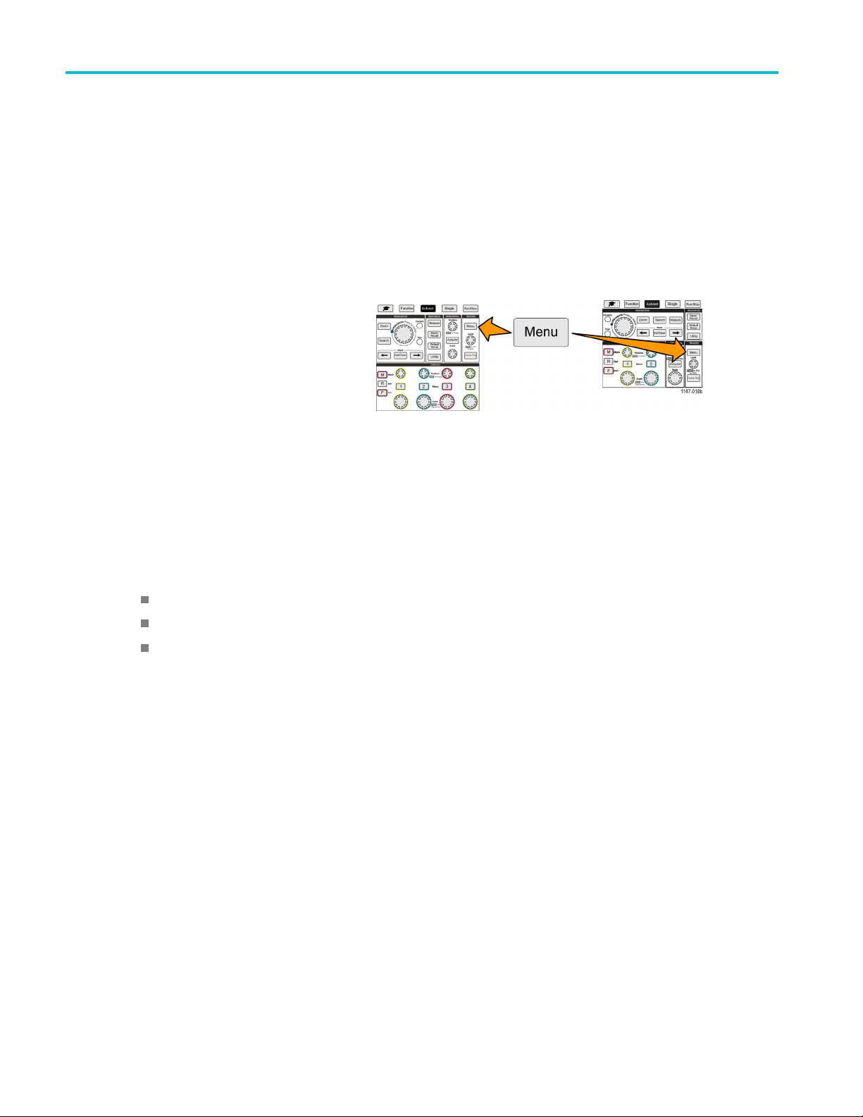
Trigger setup
Triggering on a runt pulse
Use this procedure to set the o scilloscope to trigger when a runt pulse occurs. You can also trigger when a runt pulse is less
than, greater than, equal to, or not equal to a set time period (width).
A runt pulse is a pulse that crosses one threshold level but fails to cross a second threshold before recrossing the first.
Therefore, a runt trigger needs two threshold levels to define the two levels that a signal must pass through to be considered
a valid (nonrunt) signal. (See page 26, Available trigger types.)
Runt pulse triggering is most often used to troubleshoot or analyze digital signals.
The minimum runt pulse width setting is 1 ns.
1. Push the Trigger Menu front-panel button.
2. Push the Type side-menu button.
3. Use the Mu
4. Push the Source side-menu button and use the Multipurpose knob to select and click the channel to use as the trigger
signal s
5. Push the Polarity side-menu button and use the Multipurpose knob to select and click the runt pulse polarity (positive,
negativ
6. Push the Thresholds side-menu button and use the M ultipurpo se knob to select and click the trigger levels (thresholds) to
use to d
Click High and use the Multipurpose knob to manually set the level that defines a valid high signal threshold level.
Click Low and use the Multipurpose knob to manually set the level that defines a valid low signal threshold level.
Clic
7. Pus
any runt event. If triggering on a runt width, use the Multipurpose knob to select and click the runt pulse width condition to
test for, and enter the runt width time parameter.
ltipurpose knob to select and click Runt.
ource, or select AC Line to use the AC power source frequency as the trigger signal.
e, or either) to trigger on.
etect a runt pulse:
k Choose Preset and use the Multipurpose knob to set the trigger threshold levels to predefined signal logic family
levels (TTL, CMOS, ECL, and so on) or to 0.
htheTrigger When side-menu button and use the Multipurpose knob to select and click Runt Occurs to trigger on
36 TBS2000 Series User Manual
Page 55

Setting the trigger mode
Use this procedure to set the oscilloscope trigger Mode. The trigger mode sets how the oscilloscope behaves in the absence
or presence of a trigger. Trigger mode also enables the trigger holdoff function. (See page 27, Trigger modes.)
Trigger mode does not set the trigger conditions; those are set with the Trigger Type side-menu buttons.
1. Push the Trigger Menu front-panel button.
2. Push the Mode side-menu button.
Trigger setup
3. Use the Mul
Click Auto (Untriggered Roll) to set the oscilloscope to acquire and display a waveform even if a trigger does not
occur. If
(Untriggered Roll) trigger mode.)
Click No
page 27, Normal trigger mode.)
Click H
the holdoff period is over, the oscilloscope starts looking for the trigger condition. The minimum holdoff period is
20 ns. (See page 27, Holdoff trigger mode.)
tipurpose knob to select and click a trigger mode or holdoff mode:
there is no valid triggering event, the waveform will appear to roll across the s creen.(See page 27, Auto
rmal to set the oscilloscope to acquire and display a waveform only when a v alid trigger event occurs. (See
oldoff to set a time period after a trigger event, during which the oscilloscope ignores new trigger events. Once
TBS2000 Series User Manual 37
Page 56
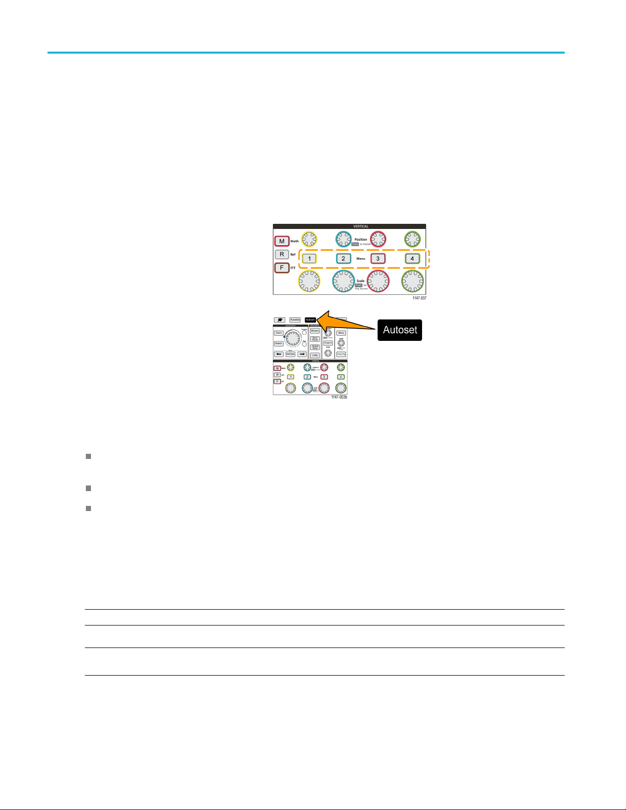
Acquisition set
up
Acquisition setup
This section describes procedures for setting the oscilloscope acquisition parameters.
Using Autoset
Autoset is a fast way to acquire and display a waveform. Autoset automatically sets the trigger type to edge, sets the
threshold le
and vertical settings to display five to six w aveform cycles. Autoset is ideal for quickly displaying a repeating signal waveform.
1. Connect a probe to the oscilloscope and
vel to 50% of the signal level, and analyzes the input signal and adjusts the oscilloscope acquisition, horizontal,
signal sour
ce.
2. Push the Ve
channel input that you want to Autoset,to
enable that channel.
3. Push Auto
few moments to analyze and display the
signal.
4. You can push the Undo Autoset side-menu
button to
rtical Menu button for the
set. The oscilloscope takes a
undo the last Autoset.
Autoset tips
If more than one channel is active, Autoset triggers on the lowest-numbered displayed channel, and displays all
active channels from the top to the bottom of the screen.
Autoset always sets vertical offset to 0 V.
Channel 1 is a special case: If all channels are off (not displayed), or channel 1 is on, Autoset attempts to detec t, trigger,
and display the waveform for channel 1 even if no signal is present (resulting in a flat waveform for channel 1). It will not
trigger on, or display the other channels, even if there are signals present on those channels.
How to disable Autoset in the oscilloscope
You can disable the Autoset button to require setting the oscilloscope controls manually to display a waveform.
E. To disable or enable the Autoset function requires a password. The default factory password is 000000.
NOT
NOTE. An instructor in a TekSmartlab™-equipped education lab can enable or disable Autoset from the TekSmartLab
application, for all connected oscilloscopes.
38 TBS2000 Series User Manual
Page 57
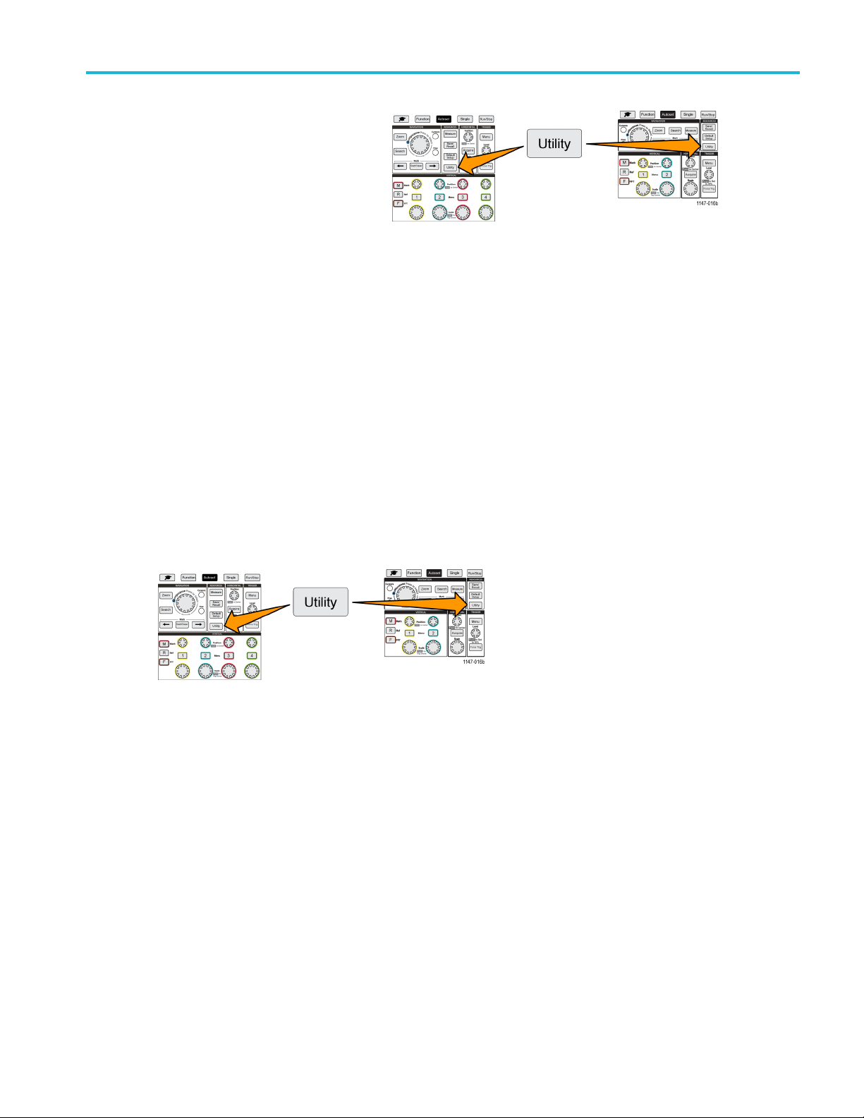
Acquisition set
1. Push Utility.
2. Push -More- P a ge 1/2 side-menu button.
3. Push Autoset Enable side-menu button.
4. Use the Multipurpose knob to select and click Autoset Enable. The oscilloscope opens the Autoset Enable password
entry screen.
5. Use the Multipurpose knob and side-menu buttons to enter the password that lets you disable Autoset. The factory
default password is 000000
6. Push OK side-menu button to enter the password and let you disable Autoset.
up
How to change the Autoset password
Use this procedure to change the Autoset Enable/Disable password. Autoset requires a password to enable or disable
the Autoset mode.
1. Push Utility.
2. Push -More- Page 1/2 side-menu button.
3. Push Autoset Enable side-menu button.
4. Use the Multipurpose knob to select and click Change Password. The oscilloscope opens the Change Password
entry screen.
5. Use the Multipurpo se knob and side-menu buttons to select alphanumeric and enter characters for the current
password. Then push the OK side-menu button. The factory default password is 000000.
6. Use the Multipurpose knob and side-menu buttons to enter the new password. Then push the OK side-menu button.
Reenter the new password to confirm it and push the OK side-menu button.
TBS2000 Series User Manual 39
Page 58

Acquisition set
up
Starting and stopping an acquisition
After you have defined the acquisition and trigger parameters, start acquiring and displaying a waveform with the Run/Stop
or Single controls.
Push Run/Stop to start acquisitions
(button turns green). The oscilloscope
acquires repeatedly until you push the
button again to stop the acquisition, or
push the Single button.
Push Single to take a single acquisition.
Single sets the trigger mode to Normal
for the single acquisition.
Setting the acquisition mode
Use the a
and display a waveform. (See page 23, Acquisition mode concepts.)
1. Push Acquire.
2. Push the Mode side-menu button.
3. Turn the Multipurpose knob to select a mode (Sample, Peak Detect, Hi res, Average), then click the Multip urpose
4. If you selected Average,usetheMultipurpose knob to select and set how many acquisitions to average to create
cquisition mode to set how the oscilloscope uses the sampled data points in each acquisition interval to create
knob to enable that mode.
the waveform.
40 TBS2000 Series User Manual
Page 59

Setting the acquisition trigger delay time
1. Push Acquire.
2. Push the Delay side-menu button to toggle
between On and Off. When set to Off,the
expansion point is tied to the trigger point so
that horizontal scale changes are centered
around the trigger point.
3. With Delay set to On, the trigger point is
disconnected from the expansion point.
Turn the Horizontal Position knob to move
the trigger point away from the expansion
point (center graticule). The amount of
delay is shown in the Horizontal Status
area at the bottom-center of the graticule,
referenced to 0 s (center graticule).
The trigger point can move off the screen;
when this happens, the trigger marker
changes to show the direction of the trigger
point.
Acquisition set
up
Trigger point is off-screen (delay time shown on readout at bottom of the screen)
4. Once you are displaying a waveform area of interest at the center of the screen, adjust the Horizontal Scale knob to
acquire more points for the area of interest, and use the controls to view more detail.
5. Push the Set Horizontal Position to 0s side-menu button to return the trigger point to the center of the waveform record
(setting delay to 0). Pushing this button does not turn off the delay mode.
You can also push the front-panel Horizontal Position knob to return the trigger point to the center of the waveform record.
Trigger Delay is different than Trigger Holdoff. (See page 27, Holdoff trigger mode.)
TBS2000 Series User Manual 41
Page 60

Acquisition set
up
Setting the record length
Use this procedure to set the record length. The record length sets how many samples (data points) are added to a waveform
record. Available record lengths are 2000; 20,000; 200,000; 2 million (2M); and 20 million (20M) points.
NOTE. 20M waveforms cannot be loaded into reference memory, either directly from the oscilloscope or from a saved file.
All other record length waveforms can be loaded into reference memory.
1. Push Acquire.
2. Push the Record Length side-menu button.
3. Use the Mu
Use longer record lengths to either capture
more samples for a waveform record, or
capture m
use the Zoom controls to investigate the
waveform in more detail.
ltipurpose knob to select and set the record length.
ore cycles of a waveform, then
Maximum Zoomed waveform record captured with 2000 points
Maximum Zoomed waveform record captu red with 2 million points
42 TBS2000 Series User Manual
Page 61

Using the roll display mode
Roll mode gives a display similar to a strip chart recorder, in t hat the waveform moves slowly, or rolls, from right to left on
the screen. Roll mode is used to display low-frequency signals. Roll mode lets you see acquired data points without
waiting for the acquisition of a complete waveform record.
Roll mode is not a button- or menu-selected mode, but is present when the trigger mode is Auto and the horizontal scale and
record lengths are set as follows:
Table 1: Roll mode is enabled when:
Horizontal scale setting Record length (number of samples)
40 ms/div
400 ms/div
Roll mode tips
Push Run/Stop to halt Roll mode.
Role mode is disabled under the following conditions:
When using Reference, Math,orFFT waveforms
2000, 20k, 200k, 2M
20M
Acquisition set
up
Using the Zoom function
Taking measurements (Measure menu)
Change to Normal trigger mode
Set the horizontal scale to 20 ms/division or faster (for 20M record lengths, it is 200 ms/division or faster)
Average acquisition mode is not available when you are using Roll mode
ng the oscilloscope to factory default values (Default Setup)
Setti
Default Setup clears the current oscilloscope settings and loads factory-defined settings. This lets you quickly reset the
oscilloscope to a known state before setting up to take a new measurement.
(See page 113, The default oscilloscope settings (Default Setup).)
To return the oscilloscope to its factory default settings:
1. Push Default Setup.
2. If you change your mind, push Undo Default Setup side-menu button to return the oscilloscope to the settings present
before you pushed Default Setup. You must push this button before doing any other action.
TBS2000 Series User Manual 43
Page 62

Waveform displa
y settings
Waveform disp
This section contains concepts and procedures for displaying and removing a w aveform.
lay settings
Displaying and removing a waveform
Use this procedure to turn on or off the display of each channel’s waveform.
1. To add or remove a waveform from
the display, push the corresponding
front-panel channel Menu button.
If the selected channel is already active, pushing the channel Menu button removes the waveform.
If the channel is not active, pushing the channel Menu button selects that channel; another push removes the waveform
from the screen.
If more than one waveform is on the screen, selecting a channel draws the corresponding waveform on top of all other
waveforms.
Setting the waveform persistence
Persistence sets the time for how long the oscilloscope retains and displays the sampled waveform points on the screen.
Using longer or infinite persistence times helps to display infrequent or random signal anomalies such as glitches.
Normal persistence sets the oscilloscope to erase the current waveform data as it draws the newest acquisition. Changing
the persis tence time (from 1 second to 10 seconds) set
screen until they are erased. The older data points are erased first.
Infinite persistence sets the oscilloscope to retain and display all acquisition waveform data points without erasing the
previous data.
Changing an acquisition setting, such as Horizontal Position or Scale, Autoset, and Single, resets the persistence period
to start over.
1. Push Acquire.
2. Push Waveform Display side-menu button.
3. Use the Multipurpose knob to select and click Persist Time.
s how long to retain waveform data points in memory and on the
44 TBS2000 Series User Manual
Page 63

4. Use the Multipurpose knob to change and set the Persist Time value. The range is Auto (which is the same as 0 s), 0 s 10 s (in one second increments), and infinity.
5. To clear the persistence of the displayed waveform, select and click Clear Persistence. This does not change the
persistence setting, but just clears the displayed waveform persistence data.
Waveform persistence tip
To quickly clear the displayed waveform persistence data, push Single, then push Run/Stop to restart active waveform
acquisition.
The XY display mode
Waveform displa
y settings
The XY dis
is the horizontal axis and channel 2 is the vertical axis. XY display mode is useful for showing signal phase or frequency
relationships between periodic signals. The resulting XY plots are called Lissajou patterns.
You can display Ch 1 versus Ch 2. On four-channel models, you can also display Ch 3 versus Ch 4.
1. Select t
2. Push Acquire.
3. Push XY Display side-menu button to
play mode plots the signal amplitude of channel 1 (X) against the amplitude of channel 2 (Y), where channel 1
he two s ignal sources that you
want to plot. Push the Vertical Position
knob for each channel to set the ground
ce of both signals to 0 V (center
referen
horizontal graticule) so that the XY plot
is centered on the screen.
toggle XY display mode On and Off.
TBS2000 Series User Manual 45
Page 64

Waveform displa
y settings
XY display mode tips
Because the XY display is simply a different way of displaying pairs of waveforms, the underlying waveforms are
available for measurements, and for saving to reference m emory or a USB drive for off-line analysis.
Use a Web browser and search on the keyword “lissajou patterns” to find more information on XY plots.
Setting the backlight intensity
Use this proc
lower values are better for dimly lighted areas.
1. Push Utility.
2. Push the Display side-menu button.
3. Use the Multipurpose knob to select and click Backlight Intensity.
4. Use the Multipurpose knob to change and set the backlight value.
edure to change the overall screen lighting level. Higher settings are better for brightly lighted areas, and
46 TBS2000 Series User Manual
Page 65
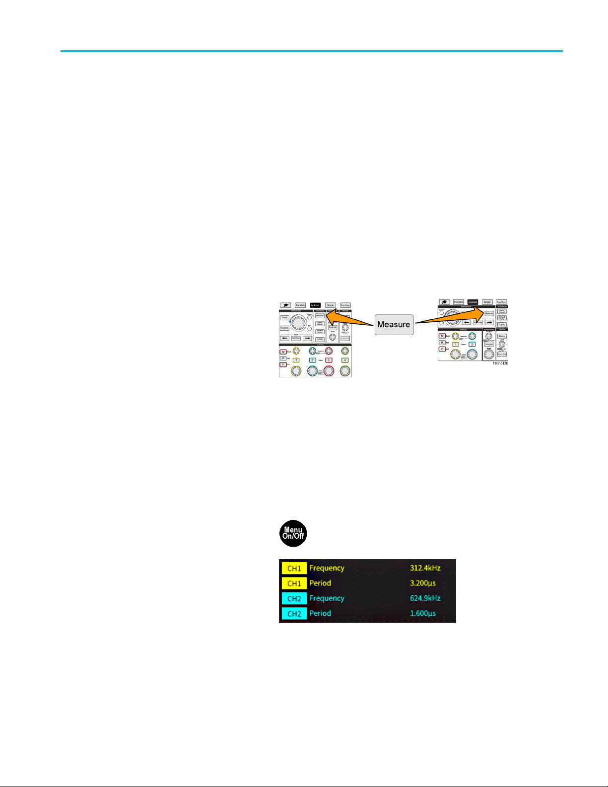
Analyzing a wave
form
Analyzing a wa
After having properly set up the acquisition, triggering, and display of your waveform, you can then analyze the results.
Select from features such as displaying automatic measurements, using cursors to measure specific parts of a waveform,
using math to perform an operation on two waveforms, and using FFT to display the frequency components of a signal. You
canalsouseGating to analyze only a specified part of a waveform when you take measurements. (See page 52, Ta k in g a
measurement on just a part of the waveform (Gating).)
veform
Ta king automatic m easurements
Automatic measurements a re a way to quickly take common measurements on a waveform, such as signal frequency,
period, ris
channels and a math waveform. The measurements are shown on the main screen in the order they were selected.
To take an automatic measurement:
1. Acquire and display a triggered waveform.
2. Push Meas
3. Push the s
e and fall times, and so on. You can take up to a total of six measurements at once, on any combination of input
ure.
ide-menu button to select the
channel on which to take measurements.
4. Use the Multipurpose knob to select and click a measurement. (See page 49, Automatic measurement descriptions.)
The Measurement Selection bar at the top of the screen updates to show that a measurement was selected for that
channel (indicated by color), up to a maximum of six measurements total to display.
5. Measurements with a down triangle contain a list of the input channels to use for that measurement when selected. Select
and click the input channels. Then push the Menu On/Off button to close the list.
6. To unselect a measurement, highlight that measurement and click the Multipurpose knob. To deselect a measurement for
a different channel than the current channel, push the side-menu button for the channel of the measurement, then use the
knob to select and click the measurement to remove it.
7. To unselect all measurements, push the Remove All Measurements side-menu button.
8. To close the measurement menu and show
the selected measurements on the screen,
push the Menu On/Off button.
Measurements are shown on the screen.
Pushing the Menu On/Off button also turns
on or off showing the measurements on the
screen.
TBS2000 Series User Manual 47
Page 66

Analyzing a wave
form
Automatic measurements tip
A symbol appears next to a measurement if a vertical signal clipping condition exists. Part of the waveform is above
or below the upper or lower edge of the screen. Signal clipping causes inaccurate measurements. To obtain an accurate
measurement, turn the Vertical Scale and Position knobs so that all of the waveform is on the screen.
Taking a measurements snapshot
The Snapshot measurement (in the Measurem ent menu) displays all single-channel measurements on one screen
for a single acquisition of one channel. You can view the snapshot results and save a screen image of the snapshot
measuremen
ts to a file.
Totakeamea
1. Acquire and display a triggered waveform.
2. Push Measure.
3. Push the side-menu button of the channel for which to show the measurement snapshot. You can only take a snapshot
of one channel at a time.
4. Use the Multipurpose knob to select and click S napshot. the snapshot screen opens immediately.
5. If the File Save button is set to save an
image, push the File Save buttontosave
the snapshot image to a file. (See page 67,
Saving fi les to USB with the Save File
button.)
6. Push the Menu On/Off button to close
the Snapshot screen and return to the
measurements menu.
surements snapshot:
Snapshot measurement tip
measurement snapshot does not mark a measurement if a vertical clipping condition exists. Clipping is where part of
The
the waveform is above or below the display. To obtain a proper measurement snapshot, use the Vertical Scale and
Position knobs to make all of the waveform appear in the display.
You can also use Gating to analyze only a specified part of a waveform when you take a measurement snapshot. (See
ge 52, Taking a measurement on just a part of the waveform (Gating).)
pa
48 TBS2000 Series User Manual
Page 67

Automatic measurement descriptions
The following tables list the automatic measurements, grouped as shown on the measurements menu. Measurement
descriptions can also be shown on the oscilloscope by enabling Help Everywhere (Function > Help Everywhere). (See
page 19, Getting on-screen help for settings: Help Everywhere.)
Frequency measurement descriptions
Frequency measurements
Measurement Description
Frequency
The first cycle in a waveform or gated region. Frequency is the reciprocal of the period; it
is measured in hertz (Hz) where one Hz is one cycle per second.
Analyzing a wave
form
+Pulses
–Pulses
+Edges
–Edges
The number of positive pulses that rise above the mid reference crossing in the
waveform or gated region.
The number of negative pulses that fall below the mid reference crossing in the waveform
or gated region.
The number of positive transitions from the low reference value to the high reference
value in the waveform or gated region.
The number of negative transitions from the high reference value to the low reference
value in the waveform or gated region.
Time measurement descriptio ns
Time measurements
Measurement Description
Period
Rise Time
TBS2000 Series User Manual 49
The time required to complete the first cycle in a waveform or gated region. Period is
the reciprocal of frequency and is measured in seconds.
The time required for the leading edge of the first pulse in the waveform or gated region
to rise from the low reference value to the high reference value of the final value.
Page 68
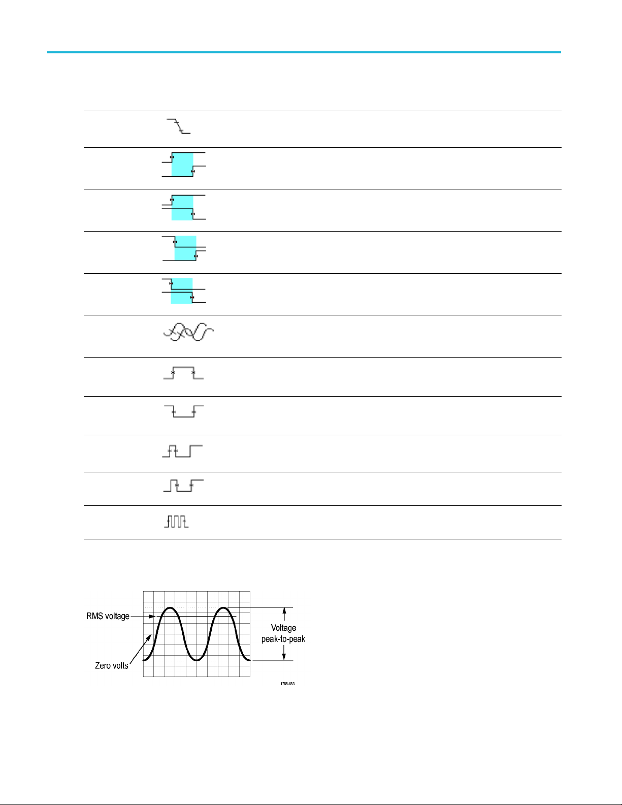
Analyzing a wave
Time measurements (cont.)
Measurement Description
Fall Time
form
The time required for the falling edge of the first pulse in the waveform or gated region to
fall from the high reference value to the low reference value of the final value.
DelayRR
DelayRF
DelayFR
DelayFF
Phase
+Width
–Width
ty
+Du
The time between the mid reference (default 50%) amplitude point of the rising edge of
two differe
This measurement requires inputs from two channels.
The time between the mid reference (default 50%) amplitude point of the rising edge of
one waveform and the falling edge of a second waveforms. See also Phase.
This measu
Thetimeb
one waveform and the rising edge of a second waveforms. See also Phase.
This measurement requires inputs from two channels.
The time between the mid reference (default 50%) amplitude point of the falling edge of
one wave
This measurement requires inputs from two channels.
The amount of time that one waveform leads or lags another waveform, expressed in
degrees, where 360° makes up one waveform cycle. See also Delay(RR, RF, FR, FF).
This m
Posit
amplitude points of a positive pulse. T he measurement is made on the first pulse in
the waveform or gated region.
Negative pulse width. The distance (time) between the m id reference (default 50%)
ampl
the waveform or gated region.
The ratio of the positive pulse width to the signal period expressed as a percentage. The
duty cycle is measured on the first cycle in the waveform or gated region.
nt waveforms. See also Phase.
rement requires inputs from two channels.
etween the mid reference (default 50%) amplitude point of the falling edge of
form and the falling edge of a second waveforms. See also Phase.
easurement requires inputs from two channels.
ive pulse width. The distance (time) between the mid reference (default 50%)
itude points of a negative pulse. The measurement is made on the first pulse in
–Duty
Burst Width
The ratio of the negative pulse width to the signal period expressed as a percentage.
The duty cycle is measured on the first cycle in the waveform or gated region.
The duration of a burst (a series of transient events) and is measured over the entire
waveform or gated region.
Amplitude measurement descriptions
50 TBS2000 Series User Manual
Page 69
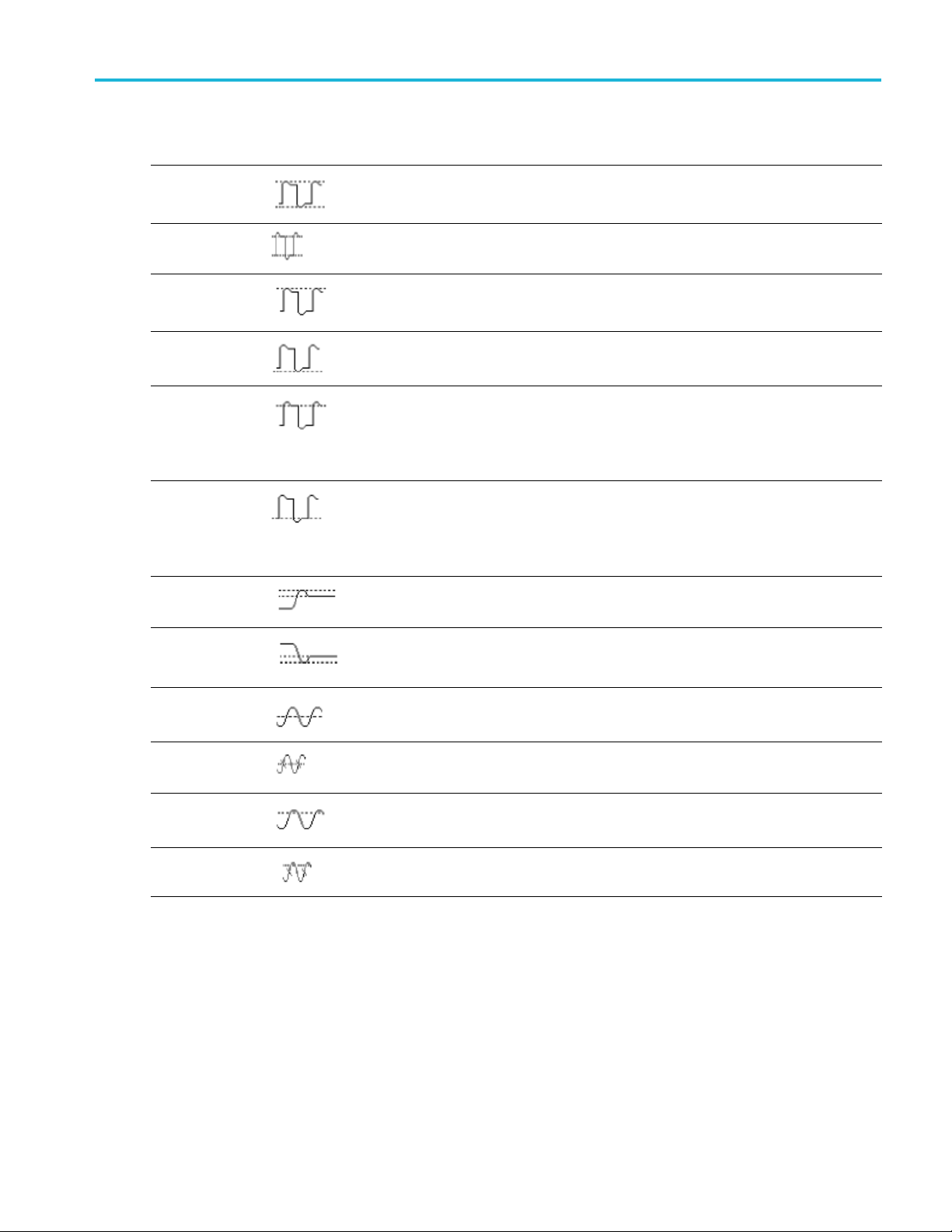
Amplitude measurements
Measurement Description
Peak-to-peak
The absolute difference between the maximum and minimum amplitude in the entire
waveform or ga
ted region.
Analyzing a wave
form
Amplitude
Max
Min
High
Low
+Over This is measured over the entire waveform or gated region and is expressed as:
–Over This is measured over the entire waveform or gated region and is expressed as:
The average h
or gated region.
The most positive peak voltage. Max is measured over the entire waveform or gated
region.
The most negative peak voltage. Min is measured over the entire waveform or gated
region.
This value is used as 100% whenever high reference, mid reference, or low reference
values are needed, such as in fall time or rise time measurements. Calculated using
either the min/max or histogram method. The min/max method uses the maximum value
found. The histogram method uses the m ost common value found above the midpoint.
This value is measured over the entire waveform or gated region.
This value is used as 0% whenever high reference, mid reference, or low reference
values are needed, such as in fall time or rise time measurements. Calculated using
either the min/max or histogram method. The min/max method uses the minimum value
found. The histogram method uses the most common value found below the midpoint.
This value is measured over the entire waveform or gated region.
Positive O vershoot = (Maximum – High) / Amplitude x 100%.
Negative Overshoot = (Low – Minimum) / Amplitude x 100%.
igh value less the average low value measured over the entire waveform
Mean
Mean
Cycle
RMS The true Root Mean Square voltage over the entire waveform or gated region.
Cycle RMS The true R oot Mean Square voltage over the first cycle in the waveform or the first
ithmetic mean over the entire waveform or gated region.
The ar
ithmetic mean over the first cycle in the waveform or the first cycle in the gated
The ar
region.
e in the gated region.
cycl
TBS2000 Series User Manual 51
Page 70

Analyzing a wave
form
Area measurement descriptions
Area measurements
Measurement Description
Area A voltage over
waveform or gated region in volt-seconds. A rea measured above ground is positive;
area measured below ground is negative.
Cycle Area A voltage over time measurement. The measurement is the area over the first cycle
in the wavef
area above the common reference point is positive, and the area below the common
reference point is negative.
time measurement. The measurement returns the area over the entire
orm or the first cycle in the gated region expressed in volt-seconds. The
Taking a measurement on just a part of the waveform (Gating)
Gating sets the automatic measurements to use only a specified part of a waveform for the measurements. The Gating
function applies to all channels and all measurements (in other words, you cannot set a different gating region for individual
measurements or different channels).
1. Push Measure.
2. Push the Gating side-menu button.
3. Use the Multipurp ose knob to select and click the area of the waveform to use for taking measurements (Off (Full
Record), Screen, Between Cursors)
If selecting Between Cursors,usethe
Multipurpose knob to select and move the
g cursors to mark the waveform area
gatin
to use for automatic measurements.
52 TBS2000 Series User Manual
Page 71
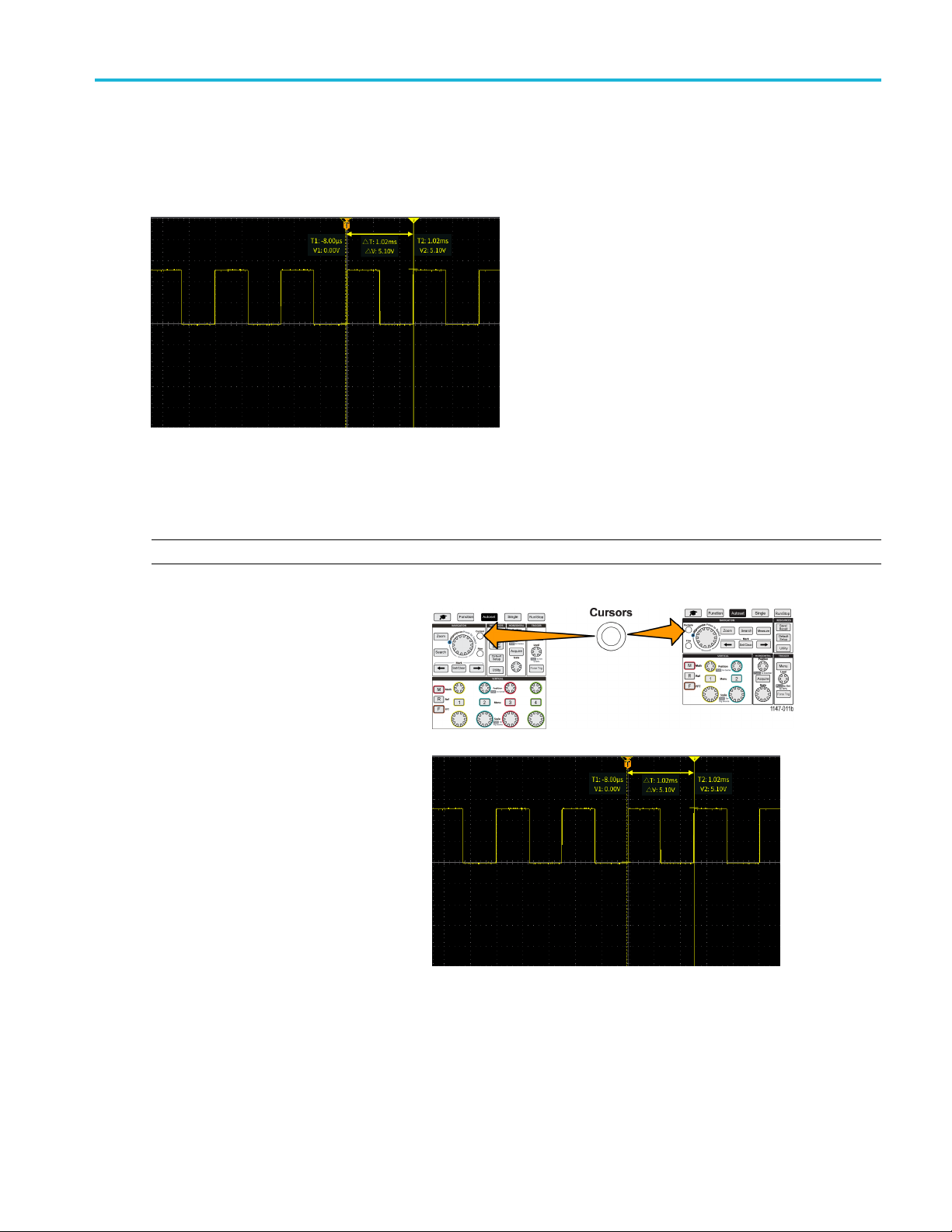
Using cursors to take manual measurements
Cursors are on-screen vertical and horizontal lines that you position on a waveform to take measurements. The cursors have
readouts that show the value at their position or where they cross a waveform. Cursors also show the absolute difference
measurement value (or delta) between two cursor positions.
Cursor readouts appear next to the cursors. The readouts show the signal values at the current cursor positions. The
readouts also show the difference (delta, m arked with a symbol) between the cursor measurements. The oscilloscope
always shows the readouts when the cursors are turned on.
Analyzing a wave
form
NOTE. Cursors are not available in XY display mode.
1. Push Cursors to display two vertical
Time cursors by default.
The color of the cursors indicates
the channel on which they are taking
rements.
measu
The solid line cursor is the active
(selected) cursor, and is controlled by
ultipurpose knob.
the M
2. Use t
he Multipurpose knob to move the
solid line (selected) cursor. The readouts
associated with that cursor change as
move the cursor.
you
TBS2000 Series User Manual 53
Page 72

Analyzing a wave
form
3. Push the Multip
the other cursor (which becomes a solid
line), then turn the knob to move that
cursor. T he fir
a dotted line.
4. To m ak e s m al l
adjustments, push the Fine button to
toggle between making coarse and fine
cursor posit
The Fine button also enables smaller
adjustments on the Vertical and
Horizontal
Level knob, and many adjustment
operations of the Multipurpose knob.
5. Push the Amplitude or Screen side-menu button to select a different cursor for taking measurements. (See page 54,
Cursor ty
6. Push the L
moves both cursors at the same time.
7. If one or both of the cursors are off of the screen, push the Bring Cursor On Screen side-menu button to bring
off-screen cursors back to the screen.
urpose knob to select
st cursor is now drawn with
er cursor position
ion adjustments.
Position knobs, the Trigger
pes.)
ink side-menu button to turn cursor linking On or Off. If linking is On, turning the Multipurpose knob
8. Push the Cursors front panel button to turn the cursors off.
r types
Curso
The cursor types are:
Time or Frequency cursors. These vertical
cursors measure time or frequency, the
signal amplitude where the cursors cross the
waveform, and the absolute difference (delta)
between the two cursors cross points (both
time and amplitude delta).
Time readouts are relative to the trigger point
(which is 0 s). For example, cursors to the left
of the trigger are m inus time values.
Amplitude cursors. These horizontal cursors
measure vertical amplitude parameters,
typically voltage.
54 TBS2000 Series User Manual
Page 73
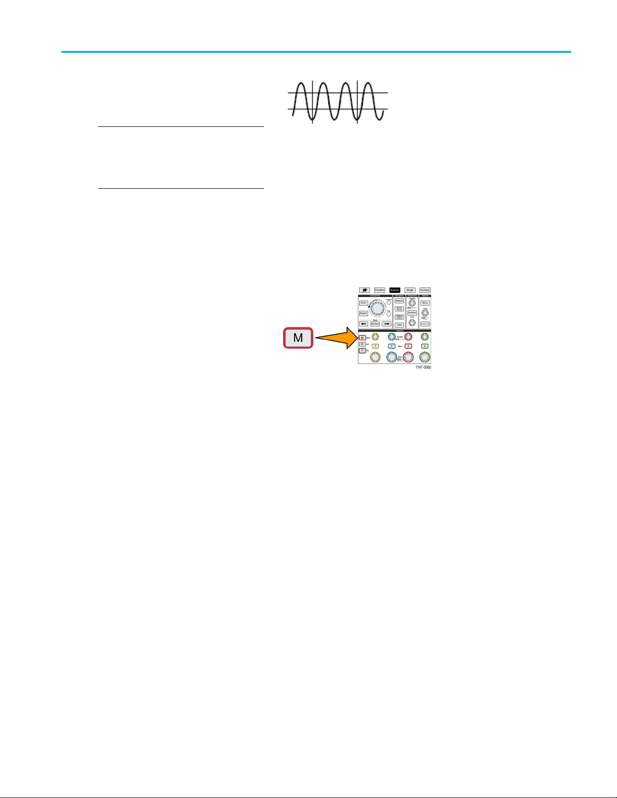
Screen cursors: A combination of both the
vertical and horizontal cursors. Click the
Multipurpose
the cursors.
NOTE. The vertical cursors in screen mode
are not tied t
waveform, and so do not show the amplitude
value where they cross the signal. Amplitude
values are re
knob to cycle through selecting
o where the cursor crosses the
ad from the horizontal cursors.
Creating math waveforms
Math waveforms let you add, subtract, and multiply any two channel waveforms to create a new math waveform. You can
then take measurements on the math waveform, or save it to a reference memory or an external waveform data file.
1. Push M(Math). The oscilloscope displays
a red math waveform using the current side
menu settings.
Analyzing a wave
form
2. Push the Source 1 side-menu button.
3. Use the Multipurpose knob to select and click the first channel to use for the math waveform.
4. Push the O perator side-menu button.
5. Use the Multipurpose knob to select and click the math operation to apply to the two waveforms (add, subtract, or multiply).
6. Push the Source 2 side-menu button.
7. Use the Multipurpose knob to select and click the second channel to use for the math waveform. The oscilloscope
immediately displays the math waveform.
8. To move the math waveform vertical position, push the Position side-menu button and use the Multipurpose knob to
move the waveform.
9. To change the size (vertical scale) of the math waveform, push the Vertical Scale side-menu button and use the
Multipurpose knob to change the waveform scale.
Note that the math vertical scale setting only applies to the math waveform.
TBS2000 Series User Manual 55
Page 74

Analyzing a wave
An example of using a math waveform is
to calculate instantaneous power (current
times voltage
waveform and a current waveform.
Math waveform tip s
Math waveforms get their horizontal scale and position from the sources channels. Adjusting these c ontrols for the
source wav
form
) by multiplying a voltage
eforms also adjusts the math waveform.
Using F
There are many signals that have some sort of distortion or unwanted characteristics. Sometimes these distortions do not
affect how that signal works in the circuit. But often system clock pulses, signals induced from a nearby printed circuit path,
or noise from a power supply or other source can affect a signal and prevent it from operating correctly. The FFT function is a
powerful tool to help you find the frequencies of unwanted signals that are embedded in your main signal.
The FFT function uses Fast Fourier Transformation (FFT) mathematical calculations on the waveform data to determine the
component frequencies in the signal. The resulting waveform shows a series of ‘spikes’ along a horizontal axis, where each
spike represents a frequency component of the waveform and its amplitude. In other words, an FFT is a basic spectrum
analyzer function to analyze frequency components of a waveform.
1. Acquire and display several cycles of the
NOTE. You can only display FFT waveforms for
2000 and 20K point record length w aveforms.
Adding or
You can ta
side menu in the Measure screen and select the measurements to apply.
You can save a math waveform to a reference memory or to a file on a USB drive. You can also recall (load) math
waveforms into reference memory. (See page 69, Recalling waveform data.)
You can zoom in on math waveforms using the Navigation controls (Zoom button and Multipurpose knob).
subtracting waveforms with different units sets the math waveform units to “?”.
ke automatic measurements on math waveforms similarly as on channel waveforms. Just select the Math
FT to see signal frequency information
waveform.
2. Push F (FFT) button.
56 TBS2000 Series User Manual
Page 75

The oscilloscope shows the default FFT
screen. The lower main screen shows the
FFT waveform.
Use the Vertical Position knob of the
source channel to move the FFT waveform
up or down.
Analyzing a wave
form
3. Push Source
4. Push the Source side-menu button and use Multipurpose knob to set the source to channel 1, 2, 3,or4. The default
source is w
5. Push the Vertical Units side-menu button
and use the Mu ltipurpose knob to select
and click
Use the default dBV RMS Vertical Units
scale to see a detailed view of multiple
frequen
very different amplitudes.
Use the
an overall view of how all frequencies levels
compare to each other.
wfm side-menu button to toggle the display of the source waveform (at the top of the screen) On or Off.
hatever channel was selected before opening the FFT window.
dBV RMS or Linear RMS.
cies, even if the frequencies have
Linear RMS vertical scale to see
6. Push
7. Push
TBS2000 Series User Manual 57
the Window side-menu button and use the Multipurpose knob to select and click Hanning, Rectangular, Hamming,
or Blackman-Harris. (See page 59, About FFT windows.)
the Horizontal Center Position
side-menu button and use the
Multipurpose knob to position the
graph horizontally. The readout on the
FFT
side menu is the frequency of the waveform
point that is positioned on the center vertical
ticule. Use this to quickly measure FFT
gra
‘spike’ frequencies.
Page 76

Analyzing a wave
8. Push the Horizontal Scale side-menu
button and use the Multipurpose knob
to set the hori
major graticule division) value. Use this
to expand or contract the FFT waveform
to show mo re o
waveform expands around the center
cursor.
form
zontal scale (frequency per
r less detail. The FFT
9. Push the Cur
use the cursors to take measurements.
sors front-panel button and
FFT tips
You can only display FFT waveforms for 2000 and 20K record length waveforms.
Use the Vertical Position knob of the source channel to change the vertical position of the FFT waveform.
Use the Vertical Scale knob of the source channel to change the vertical size of the FFT waveform.
Use cursors to measure frequencies and relative signal levels.
Input signals that have a DC component or offset can cause incorrect FFT waveform component magnitude values. To
minimize the DC component, use AC Coupling on the input signal.
To reduce random noise and aliased components (See page 60.) in repetitive or single-shot events, set the oscilloscope
acquisition mode to average over 16 or more samples. Average mode attenuates signals not synchronized with the
trigger.
Do not use the Average acquisition mode if the source signal contains frequencies of interest that are not synchronized
with the trigger rate.
For transient (impulse, one-shot) signals, set the oscilloscope trigger conditions so that the transient pulse waveform is
centered in the waveform record.
58 TBS2000 Series User Manual
Page 77

Analyzing a wave
About FFT windows
The FFT algorithm applies a ‘window’ process to the source waveform record to ‘shape’ the record so that the start and stop
values for the FFT waveform are close to the same amplitude. Starting and stopping the waveform at close to the same
amplitude reduces adding artificial waveform that are not present in the actual signal. Using a window on the source signal
results in an FFT waveform that more accurately represents the source signal frequency components.
form
The different window shapes are trade-offs between frequency accuracy and magnitude accuracy. What you want to
measure, and your source signal characteristics, help you to select which w indow to use. Use the following guidelines to
select the best window for your signal analysis needs. The Hanning window is a good starting point for FFT measurements.
Table 2: FFT windows
Window type Window ‘shape’
Hanning
This is a very good window for measuring amplitude accuracy but less so for resolving
frequencies.
Use Hanning for measuring sine, periodic, and narrow band random noise. T his window
works on transients or bursts w here the signal levels before and after the event are
significantly different.
Rectangular
This is the best type of window for resolving frequencies that are very close to the same
value but worst for accurately measuring the amplitude of those frequencies. It is the best
type for measuring the frequency spectrum of nonrepetitive signals and measuring frequency
components near DC.
Use Rectangular for measuring transients or bursts where the signal level before and after the
event are almost equal. Also, use this window for equal-amplitude sine waves with frequencies
that are very close, and for b roadband random noise with a relatively slow varying spectrum.
TBS2000 Series User Manual 59
Page 78

Analyzing a wave
Table 2: FFT windows (cont.)
Window type Window ‘shape’
Hamming
This is a very good window for resolving frequencies that are very close to the same value
with somewhat improved amplitude accuracy over the rectangular window. It has a slightly
better frequency resolution than the Hanning.
Use Hamming for measuring sine, periodic, and narrow band random noise. This window
works on transients or bursts where the signal levels before and after the event are
significantly different.
Blackman-Harris
This is the best window for measuring the amplitude of frequencies but worst at resolving
frequencies.
Use Blackman-Harris for measuring predominantly single frequency waveforms to look for
higher order harmonics.
FFT and display waveform aliasing
FFT waveform problems occur when the oscilloscope acquires a signal that contains frequency components that are greater
than the Nyquist frequency (the Nyquist frequency is 1/2 of the sample rate). The frequency components that are above the
Nyquis
lower-frequency components in the FFT waveform. These incorrect components are called aliases.
form
t frequency are undersampled and appear to "fold back," or reflect, around the right edge of the g raticule, showing as
You can use the following methods to reduce or eliminate aliases:
Increase the sample rate by adjusting the Horizontal Scale front-panel knob to a faster frequency setting. Since you
increase the Nyquist frequency as you increase the horizontal sampling rate (samples/second), the aliased frequency
components should appear at their proper frequency. If the increased number of frequency components shown on the
screen makes it difficult to measure individual components, use the Horizontal Scale side-menu button in the FFT menu
to display more detail of the FFT waveform.
Use a filter on the input signal to limit the signal to frequencies below that of the Nyquist frequency. If the frequency
components you are interested in are below the built-in 20 MHz bandwidth setting, push the Vertical Menu button
and set the channel bandwidth to 20 MHz.
60 TBS2000 Series User Manual
Page 79

Displaying reference waveforms
A reference waveform is a waveform that you have stored in a nonvolatile memory location on the oscilloscope. You can use
a reference waveform as a standard against which to compare other waveforms.
You can save channel, math, and FFT waveforms to reference memory. Reference waveforms remain in memory when the
oscilloscope is powered off.
See the Saving waveform data topic to l earn how to save waveforms to reference m emory or external files. (See page 64,
Saving waveform data.)
1. Push the RReffront-panel button.
2. Push the Ref1 or Ref2 side-menu button to toggle displaying that waveform On or Off.
You can display both reference waveforms at the same time.
Analyzing a wave
form
Reference waveform tips
not position or scale a reference waveform. You should set the source waveform position and scale before saving
You can
to a reference location, so that you have space on the screen to display both the reference waveform and the live signal.
You can use Zoom to show more detail on reference waveforms.
TBS2000 Series User Manual 61
Page 80
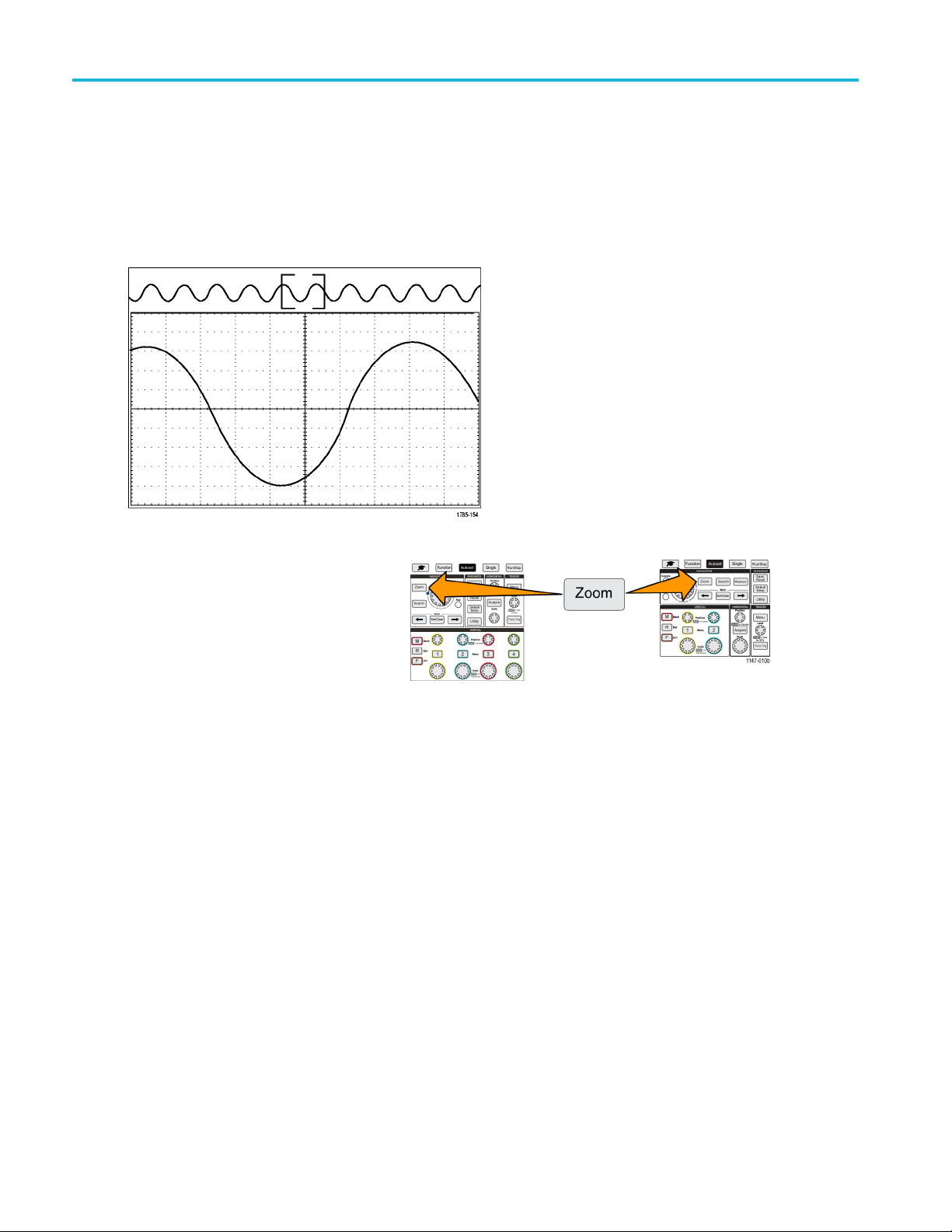
Analyzing a wave
form
How to view long record length waveforms (Zoom)
The Navigation controls (Zoom button, the Zoom side menu, and the Multipurpose knob) let you magnify and examine
portions of a waveform (Ch1-Ch4, Math, Reference).
A zoomed display consists of two parts. The upper display shows the entire displayed waveform record and the position and
size of the zoomed part in the waveform (in brackets) within the entire record. The lower display shows the zoomed view of
the waveform (the part enclosed in brackets in the upper display).
1. Select the channel that you want to
zoom.
2. Push Zoom.
3. Push t
4. Push
he Scale side-menu button and use the Multipur po se knob to adjust the size of the area to zoom (magnify).
the Position side-menu button and use the Multipurpose knob to adjust the position of the zoom area in the
waveform record.
62 TBS2000 Series User Manual
Page 81

Saving data
The oscilloscope has internal memory locations where you can save instrument setups and waveforms. You can also save
screen images, setups, and waveforms to files on an external USB drives.
Saving screen images to a file
Use this procedure to save a s creen image to a file on a USB drive. A screen image is a ‘picture’ of the oscilloscope screen.
Screen imag
NOTE. A screen image is different than waveform data. A s creen image is a picture of the screen, and does not contain any
data about the signals shown in the image. Waveform data is a file that contains the numeric values of all the sampled points
inasingle
waveform file into other oscilloscopes, or into PC-based analysis programs to perform advanced signal measurements.
1. Install a USB drive.
2. Set up the display to show the waveforms and other readouts that you want to save.
es are useful to include in reports or to compare with other screen images over time.
channel waveform. You cannot use a screen image file for further analysis, whereas you can load the data from a
Saving data
3. Push the Save/Recall front-panel button.
4. Push the Action side-menu button.
5. Use the Multipurpose knob to select and click Save Image.
6. Push the File Format side-menu button.
7. Select and click a graphical file format (BMP, JPG,orPNG).
8. Push the Save side-menu button to save the screen image to an automatically-named file at the top level of the USB drive.
(See page 75, About automatically generated file names.)
You can also set the File Save button to automatically save an image file to the USB drive. (See page 67, Saving files
to USB with the Save File button.)
TBS2000 Series User Manual 63
Page 82
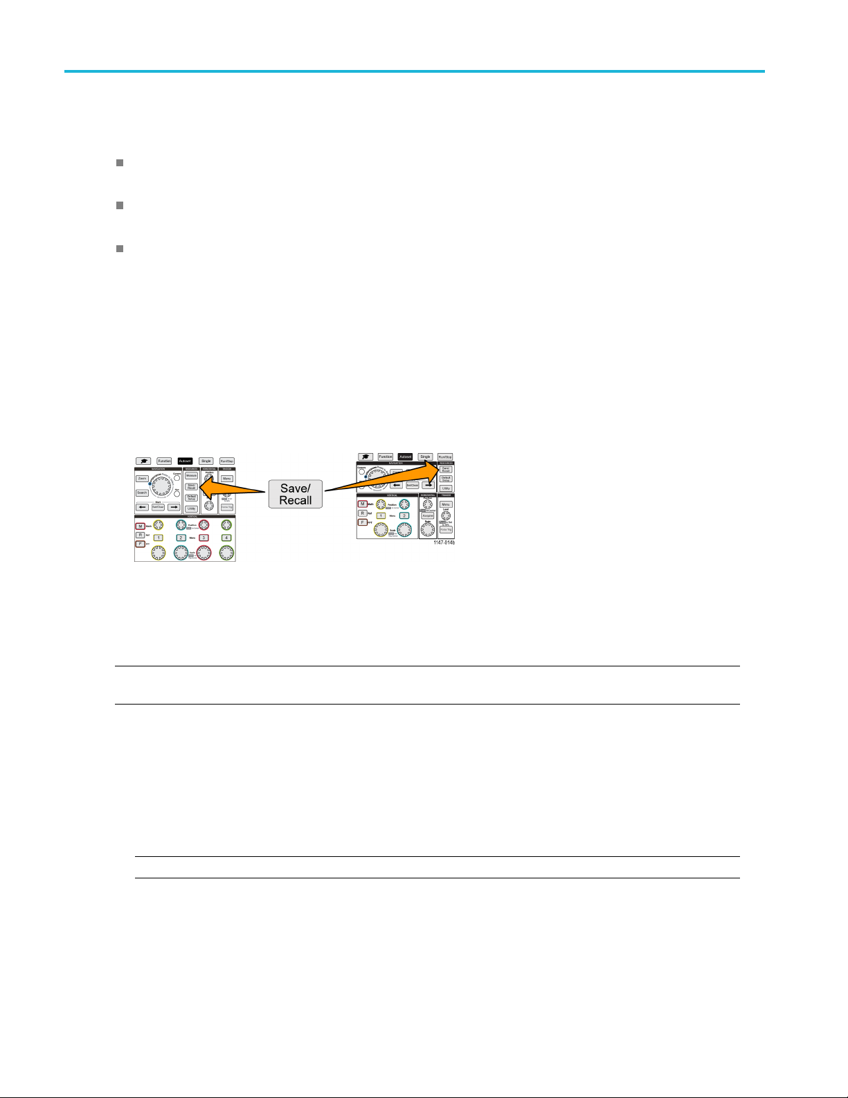
Saving data
About saved image file formats
The image save function saves screen information to three common image formats.
BMP: This bitmap format uses a lossless algorithm, and is compatible with most word processing and spreadsheet
programs; this is the default. Creates the largest file size.
JPG: This bitmap format uses a lossy compression algorithm, and is compatible with most word processing and
spreadsheet programs. Creates the smallest file size.
PNG: This bitmap format uses a lossless compression algorithm, and is compatible with most word processing and
spreadsheet programs.
Saving waveform data
Use this procedure to save waveform data to a reference (Ref) memory location or an external file.
1. (Optional) Install a USB drive to save the waveform data to a file on the USB drive.
2. Acquire and display the waveform that you want to save.
3. Push the Save/Recall front-panel button.
4. Push the Action side-menu button.
5. Use the Multipurp ose knob to select and click Save Waveform.
6. To save waveform data to internal reference memory:
NOTE. 20M record length waveforms cannot be saved to reference memory. All other record length waveforms can be
saved to reference memory.
a. Push the Save To side-menu button.
b. Select and c lick Ref.
c. Push the Source side-menu button
d. Select and click the waveform data source (CH1-CH4, Math, FFT).
NOTE. The selected waveform must be displayed on the screen to save waveform data.
64 TBS2000 Series User Manual
Page 83

e. Push the To side-menu button.
f. Select and click Ref1 or Ref2.
g. Push the Save side-menu button.
7. To save waveform data to a file on the U SB drive:
a. Push the Save To side-menu button.
b. Select and click USB File (*.ISF) or USB File (*.CSV). (See page 65, About waveform data files.)
c. Push the Source side-menu button
d. Select and click the waveform data source (CH1-CH4, Math, FFT, Ref1, Ref2).
Saving data
NOTE. The se
e. Push the Save side-menu button to s ave the waveform data to an automatically named file on the USB drive. (See
page 75, About automatically generated file names.)
About wav
.ISF (Internal File Format): Sets the oscilloscope to save waveform data from analog channels (and math and reference
waveforms derived from analog channels), in internal waveform save file (ISF) form at. This format is the fastest to
write and creates the smallest-sized file. Use this format if you intend to recall a waveform to reference memory for
viewing or measuring.
.CSV (comma separated values): Sets the oscilloscope to save waveform data as a comma-separated data file
compatible with popular spreadsheet programs. This file cannot be recalled to reference memory. A CSV file is
significantly larger than an ISF file, and takes longer to write to the USB drive.
To find out the channel for which the file was written, open the file in a text editor. The channel name is in the top
few lines of the file.
lected waveform must be displayed on the screen to save waveform data.
eform data files
TBS2000 Series User Manual 65
Page 84
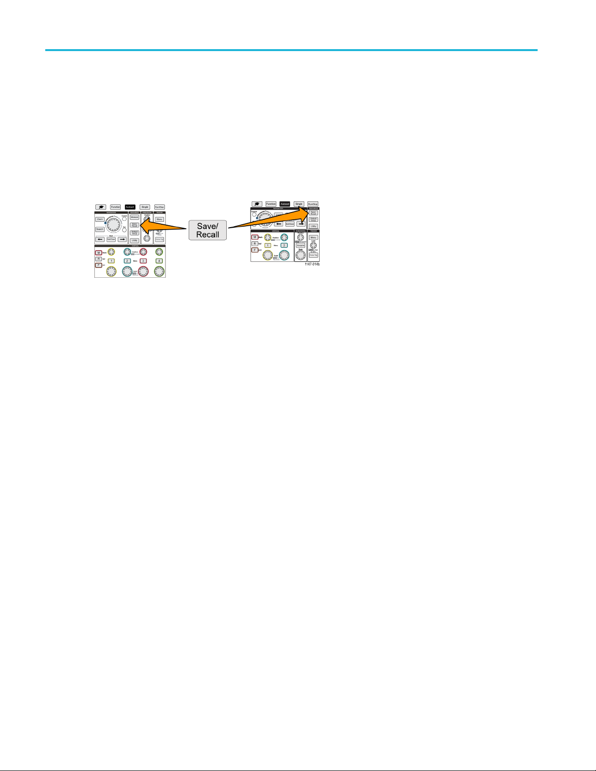
Saving data
Saving oscilloscope setup information
You can save the oscilloscope internal settings to an internal memory location (setup 1–10) or to an external file on the USB
drive. A setup file contains most of the oscilloscope settings, including vertical, horizontal, trigger, cursor, and measurement
parameters. It does not include communications information, such as GPIB addresses. You can then use the setup data to
quickly set the oscilloscope to take a certain measurement.
Use this procedure to save the current oscilloscope settings to a memory location o r external file.
1. (Optional) Install a USB drive to save the setup data to a file on the USB drive.
2. Push the Save/Recall front-panel button.
3. Push the A
4. Use the M
5. To sa v e s
a. Push Sav
b. Select a
c. Push Se
d. Push Sa
6. To sa v e
a. Push S
b. Use th
c. Push S
ction side-menu button.
ultipurpose knob to select and click Save Setup.
etup data to internal setup memory:
eToside-menu button.
nd click Setup.
tup side-menu button and use the Multipurpose knob to select the setup memory location (1-10).
ve side-menu button.
setupdatatoafile on the USB drive:
ave To side-menu button.
e Multipurpose knob to select and click USB File (*.SET file).
ave TEKxxxxx.SET side-menu button to save the setup data to an automatically named *.SET file at the top
level of the USB drive. (See page 75, About automatically generated file names.)
66 TBS2000 Series User Manual
Page 85

Saving files to USB with the Save File button
The Save File button is a quick, one-push way to save a specified data files to the USB drive. After you have defined
the save parameters with the Save/Recall button and Action side-menu button, you can assign that save action to the
Save File button. For example, if you assign Save to write waveform data to a USB drive, then each push of the Save
button saves the current waveform data to the USB drive.
NOTE. The Save button only saves files to the USB drive. You cannot assign the Save button to save information to
reference or setup memory, or to recall files from the USB drive.
NOTE. The oscilloscope saves files to the top level of the USB drive by default. You can use the Change folder button
in the File Utility side menu to set the oscilloscope to save files to a speci fic location on the USB drive. (See page 72,
Changing the default file save location on the USB drive.)
Files are saved to the USB drive using a specific naming convention. (See page 75, About automatically generated file
names.)
1. Push the Save/Recall front-panel button.
Saving data
2. Push the Assign To side-menu button.
3. Push the side-menu buttons for the action that you want to assign to the Save button (Screen Image, Waveform,or
Setup). The save button is now assigned to that action.
4. For image or setup files: Use the Save/Rec side-menu buttons to select the output format for the action you assigned to
ave button (BMP, JPG, or PNG for screen images; .ISF or .CSV for waveforms).
the S
NOTE. Setup files will always be saved as .SET files.
5. For waveform files: Use the Save/Rec side-menu buttons to select the signal source for saving waveforms (CH1-CH4 ,
h, Ref1-2).
Mat
htheSave button to confirm that the assigned file type and format was saved to the USB drive.
6. Pus
NOTE. The Assign To button does not store the current save settings (such as file format or waveform source). The Save
button uses the settings of the Save/Rec side menu to save files.
TBS2000 Series User Manual 67
Page 86
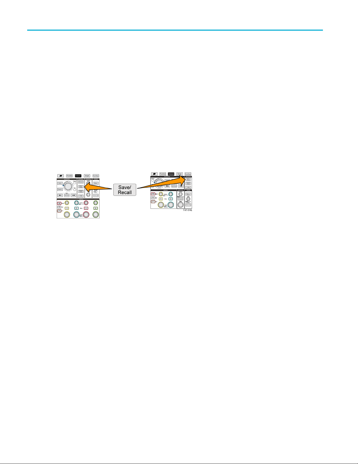
Recalling data
Recalling data
The oscilloscope provides permanent internal memory locations from which you can recall instrument setups and waveforms.
You can also recall (load) setups and waveforms from files on an external USB drive.
Recalling oscilloscope setup information
Use this proc
those settings.
You can recall (load) saved setup data to quickly configure the oscilloscope to take a certain measurement. A setup file
contains most of the oscilloscope settings, including vertical, horizontal, trigger, cursor, and measurement parameters. It
does not inc
1. (Optional
2. Push the Sa
3. Push the Action side-menu button.
4. Use the Multipurpose knob to select and click Recall Setup.
5. To recall setup data from internal setup memory:
a. Push the Recall From side-menu button.
b. Select and click Setup.
edure to recall (load) oscilloscope settings from a memory location or external file and set the oscilloscope to
lude communications information, such as GPIB or LAN configuration.
) Install a USB drive to recall the setup data from a file on the USB drive.
ve/Recall front-panel button.
c. Push the Setup side-menu button and use the Multipurpose knob to select the setup memory location (1-10).
d. Push the Recall side-menu button. The oscilloscope changes its settings to those that are in the specified setup
memory.
6. To recall (load) setup data from a file on the USB drive:
a. Push the Recall From side-menu button.
b. Select and click USB File (*.SET).
c. Push the Select File side-menu button.
d. Highlight the setup file (*.SET) to load.
e. Push the Multipurpose knob or the Recall side-menu button. The oscilloscope loads and implements the settings.
68 TBS2000 Series User Manual
Page 87
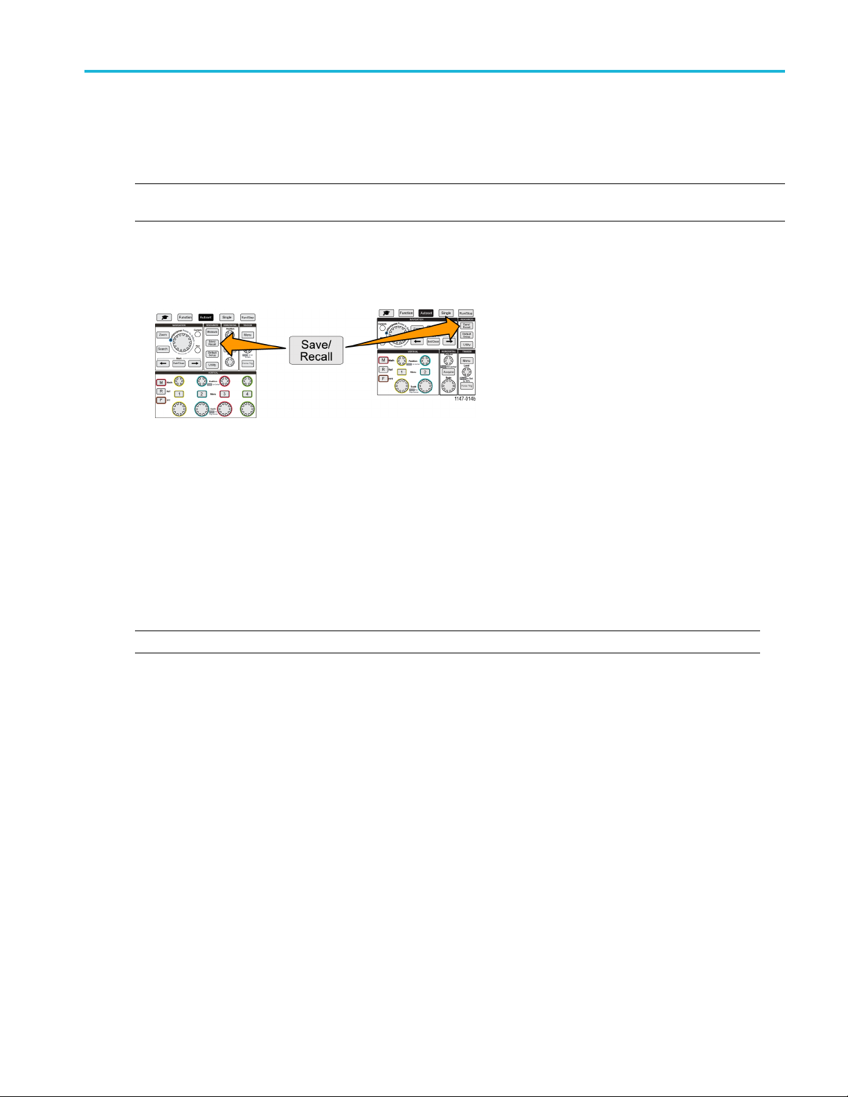
Recalling waveform data
Use this procedure to recall (load) waveform data from an external .ISF file to load into a reference memory location and
display on the oscilloscope. The oscilloscope can only load .ISF waveform data files.
NOTE. 20M record length waveforms cannot be loaded into reference memory, either directly from the oscilloscope or from
a saved file. All other record length waveforms can be loaded into reference memory.
1. Install a USB drive that contains the .ISF waveform data file.
2. Push the Save/Recall front-panel button.
3. Push the Action side-menu button.
Recalling data
4. Use the Multipurpose knob to select and click Recall Waveform.
5. Push the To side-menu button.
6. Select and click Ref1 or Ref2.
7. Push Select File side-menu button to open the File Utility pane.
8. Use the Multipurpo se knob to select the waveform file (*.ISF).
9. Push Recall side-menu button. The oscilloscope loads the waveform data into the selected reference memory.
NOTE. If the Recall side-menu button shows No file, then you have not selected an .ISF file.
TBS2000 Series User Manual 69
Page 88
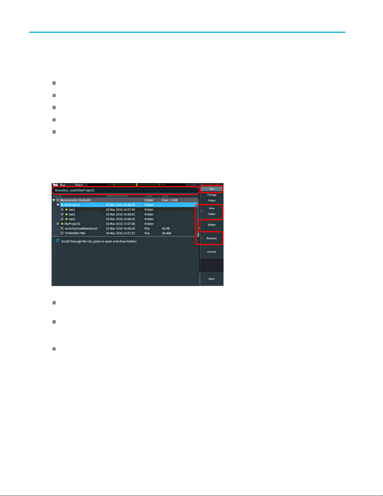
Using the USB Fil
e Utility functions
Using the USB F
Use the File Utility functions to do file-related tasks on a connected USB drive. File tasks include:
Change the default folder where files are saved.(See page 72, Changing the default file save location on the USB drive.)
Create new folders (See page 73, Creating a new folder on the USB drive.)
Delete files and folders (See page 73, Deleting files or folders from the USB drive.)
Rename files and folders (See page 74, Renaming files or folders on the USB drive .)
Format the U SB drive (See page 75, Formatting the USB drive.)
ile Utility functions
Overview of the File Utility pane
To open the File Utility pane, push the Save/Recall front-panel button and push the File Utility side-menu button.
The Directory field lists the path for the highlighted folder or file. Thisisalsothefield you use to enter text to create
or rename files or folders.
The area below the Directory field shows the files and folders. Use the Multipurpose knob to highlight a name. P ush
ltipurpose to open or close a folder. Folders are marked with a when closed, and with a when that
the Mu
folder is open.
The File side-menu buttons perform the indicated file utility functions. Change Folder, Delete, and Format directly
perform the indicated tasks.
70 TBS2000 Series User Manual
Page 89

Using the USB Fil
e Utility functions
New Folder and Rename open the character entry field, keyboard, and side-menu buttons, shown in the following image.
Use the Multipurpose knob to select and click a recently created name (listed at top of the characters list), or highlight
the indivi
dual letters of the name that you want to enter. Then push the Multipurpose knob to add that letter to the
Directory field. Repeat this process to enter the entire name.
NOTE. If you are renaming an image, waveform, or setting file, you do not need to add the extension name when renaming
the file.
Use the upper side-menu buttons to delete the character to the left of the cursor (Backspace). or move the cursor
right in the Directory field.
left or
Use the
Push th
lower side-menu buttons to show upper-or lower-case letters on the keyboard or show a numeric keypad.
e OK side-menu button to create or rename the file or folder with the name in the Directory field.
TBS2000 Series User Manual 71
Page 90

Using the USB Fil
e Utility functions
Changing the default file save location on the USB drive
By default, the oscilloscope saves image, waveform, and setup files to the top directory of the USB drive. Use this procedure
to select a different default save folder on the USB drive in which to save files.
1. Push the Save/Recall front-panel button.
2. Push the File Utility side-menu button.
3. Use the Multipurpose knob to navigate to and highlight a folder in which to save files.
4. Push the Change Folder side-menu button. Saved files will now be saved to this location.
Default save folder location rules
The new save folder location remains in effect until:
A new location is set with the Change Folder button.
The oscilloscope is powered down. The save location changes back to the top level of the USB drive.
The following actions do not change the file save location. The oscilloscope shows an error message when it tries to
save the file to a location that it cannot fi nd. Use the Change Folder function to change the working folder location
to an existing folder and try the save operation again.
Deleting the save location folder.
Removing or inserting a USB drive.
Pushing the Default Setup front-panel button.
72 TBS2000 Series User Manual
Page 91

Creating a new folder on the USB drive
Use this procedure to create a new folder on the USB drive.
1. Push the Save/Recall front-panel button.
2. Push the File Utility side-menu button.
3. Use the Multipurpose knob to navigate to the location at which to create the new folder.
4. Push the New Folder side-menu button.
5. Use the Multipurpose knob to select and click a recently created name (listed at top of the characters list), or enter the
folder name using the Multipurpose knob and side-menu buttons to scroll through and highlight letters, numbers, and
valid characters in the list.
Click the Multipurpose knob to enter the highlighted character. The characters that you enter are shown at the top of
the file pane.
Using the USB Fil
e Utility functions
6. Repeat step 5 until you have entered the folder name.
7. Push the OK side-menu button to add the new folder name to the USB drive.
NOTE. There are four names
show the most recent file or folder names that you have created. These names change back to the default values when
you power off the oscilloscope or push the Default Setup front-panel button.
at the top of the character list (default values are MyProject1-4). These names will change to
Folder creation tip
If you need to create many folders on a USB drive, it is faster to insert the USB drive into a PC and use the standard
Microsoft Windows or other OS folder creation u tilities.
Deleting files or folders from the USB drive
Use this procedure to delete files or folders from the USB drive.
1. Push the Save/Recall front-panel button.
2. Push the File Utility side-menu button.
TBS2000 Series User Manual 73
Page 92

Using the USB Fil
3. Use the Multipurpose knob to navigate to and highlight a file or folder name to delete.
4. Push the Delete side-menu button. the oscilloscope asks you confirm the delete action.
5. Highlight Yes (to delete) or No (to cancel the delete).
6. Push the Multip urp ose knob to delete the file or folder.
e Utility functions
NOTE. Deleti
CAUTION. Deleting a file or folder on the USB drive does not remove the data on the drive. It deletes the FAT table
entries for the names of the files and folders and marks the memory as available. If you have critical or secure data that
must be remo
file data with zeros.
ng a folder also deletes all files and subfolders contained in that folder.
ved from the USB drive, connect the USB drive to a PC and use a file ‘shredding’ program to replace the
Renaming files or folders on the USB drive
Use this procedure to rename files and folders from the USB drive.
1. Push the Save/Recall front-panel button.
2. Push t
3. Use th
he File Utility side-menu button.
e M ultipu rpose knob to navigate to the location at which to create the new folder.
4. Push t
5. Sele
6. Repeat step 5 until you have entered all characters of the folder name.
7. Push the OK side-menu button to add the new folder name to the USB drive.
NOT
or setting file.
Fi
If you need to rename many files or folders, it is faster to insert the USB drive into a PC and use the standard Microsoft
Windows or other OS file renaming utilities.
74 TBS2000 Series User Manual
he Rename side-menu button.
ct and click a recently created name (listed at top of the characters list), or enter the folder or file name using the
Multipurpose knob and side-menu buttons to scroll through and highlight letters, numbers, and valid characters in the list.
Push the Multipurpose knob to enter the highlighted character. The characters that you enter are shown at the top of
the file pane.
E. You do not need to add the file extension name (.ISF, .SET, and so on) when renaming an image, waveform,
le, folder renaming tip
Page 93

Formatting the USB drive
Formatting a USB drive removes the file and directory names from the drive, making the entire USB drive memory available
for new files and folders.
CAUTION. Formatting a USB drive does not remove the data on the drive. It deletes the FAT table entries for the names of
the files and folders and marks the memory as available. If you have critical or secure data that must be removed from the
USB drive, connect the USB drive to a PC and use a file ‘shredding’ program to replace the file data with zeros.
1. Push the Save/Recall front-panel button.
2. Push the File Utility side-menu button.
3. Push the Format side-menu button.
Using the USB Fil
e Utility functions
4. Use the Multipurpose knob to select and click Yes. The oscilloscope formats the drive and reopens the file utility pane.
About a
The oscilloscope automatically creates a numbered file name for the files that it saves to the USB drive.
The naming convention is TEKXXXXX.<ext>, where:
To create a new file name, the oscilloscope scans the USB drive to determine the highest-numbered file name present for the
file type being saved. The oscilloscope then increments that number and uses it for the new file name. For example, the
first time you save a file, the oscilloscope creates the file name TEK00000. The next time you save the same type of file,
the new file is named TEK00001.
Image, setting, and waveform file tips
utomatically generated file names
XXXXX is an integer from 00000 to 99999
<.ext> is the file type (.PNG, .BMP, or .JPG for screen image files; .SET for setup files; .ISF or .CSV for waveform files)
here are nonsequential jumps in the file numbering, such as TEK00001, TEK00002, TEK00005, the oscilloscope uses
If t
the highest-numbered file as the starting point for new file names (TEK00006 in this example).
If you select a different USB drive or folder location, the oscilloscope creates the file number based on the files
present in that USB drive or folder. F or example, if you select the save folder as /usb0/MyProject1, which contains file
K00006.png, the next saved .png file in that folder is named TEK00007.png.
TE
determine the channel or waveform type (Math, FFT, Ref) of a saved waveform file, open the waveform file (.CSV or
To
.ISF) in a text editor. The channel name or waveform type is at or near the top of the file structure.
TBS2000 Series User Manual 75
Page 94

Erasing data fro
m oscilloscope memory (TekSecure)
Erasing data f
The TekSecure™ function erase all setup and waveform information saved in the nonvolatile oscilloscope memory. If
you have acquired confidential waveform data on your oscilloscope, or use the oscilloscope in a restricted area, use the
TekSecure function to erase memory and setup data before you return the oscilloscope to general use.
The TekSecure function:
Replaces all waveforms in all reference memories with zero (0) values
Replaces the current front-panel setup and all stored setups with the default setup
Displays a confirmation or warning message, depending on whether the verification is successful or unsuccessful
1. Push Utility.
2. Push the Config side menu.
3. Use the Multipurpose knob to select and click TekSecure Erase Memory .
rom oscilloscope memory (TekSecure)
4. The screen shows a confirmation message.
5. Select and click OK to start the TekSecure procedure. The erase operation takes up to three minutes.
6. To cancel the procedure, select No or push the Menu Off button.
7. When the TekSecure procedure is finished, the oscilloscope automatically powers off and then powers back on.
76 TBS2000 Series User Manual
Page 95

Setting or viewi
ng USB Device port parameters
Setting or vie
Use the USB menu (Utility > Config > USB) to select the device that the USB Device port is connected to, disable the USB
Device port, and view the USBTMC protocol registration information.
NOTE. These USB controls do not disable the USB Host ports.
wing USB Device port parameters
Selecting which device is attached to the USB Device port
Use this procedure to select which device is connected to the USB Device port. A supported device does not need to be
connected to the USB Device port to select that item.
NOTE. The c
1. Push Utility front-panel button.
urrent software r elease only supports a PC connection.
2. Push the Config side-menu button. The USB menu item (at top of the Config side menu) shows the USB Device port
connection status.
3. Use the Multipurpose knob to select and click USB.TheUSB Device Port menu lists available devices to which you
can connect. A grayed out menu item cannot be selected.
4. If the USB Device port is Disabled (off Bus), select and click the device to which you want to connect.
TBS2000 Series User Manual 77
Page 96
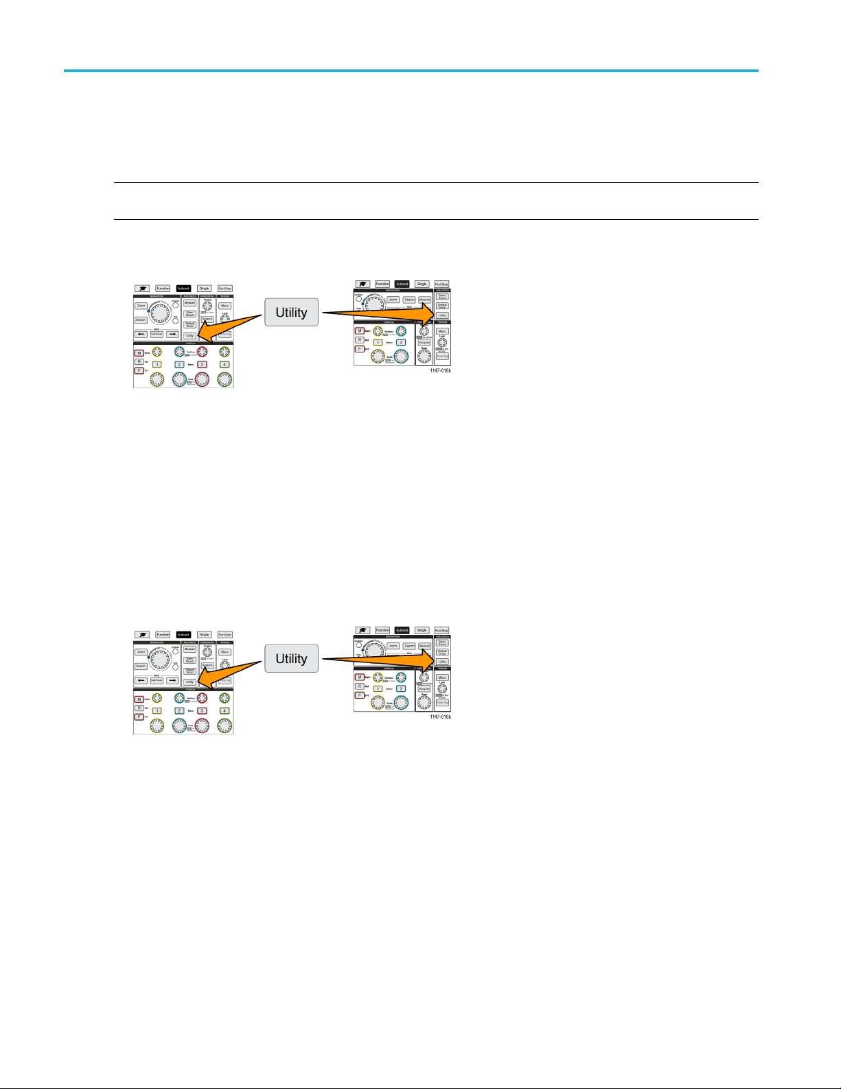
Setting or viewi
ng USB Device port parameters
Disabling the USB Device port
Use this procedure to disconnect the USB Device port access, to prevent remote access to the oscilloscope over the
USB Device port connection.
NOTE. This function only disables the rear-panel USB Device port; it does not disable the USB Host ports on the
front and rear panel.
1. Push Utility front-panel button.
2. Push the Config side-menu button.
3. Use the Multipurp ose knob to select and click USB.
4. Select and click Disabled (Off Bus).
Viewing the USBTMC information
USBTMC stands for USB Test & Measurement Class. USBTMC is a protocol that allows USB devices to communicate using
IEEE488 style messages. This protocol lets you run your GPIB software applications on USB hardware. Use this screen to
view protocol registration information. There are no active controls on this screen.
1. Push Utility front-panel button.
htheConfig side-menu button.
2. Pus
3. Use
4. Sel
the Multipurpose knob to select and click USB.
ect and click USBTMC Configuration. T he oscilloscope shows the USBTMC protocol registration information.
78 TBS2000 Series User Manual
Page 97
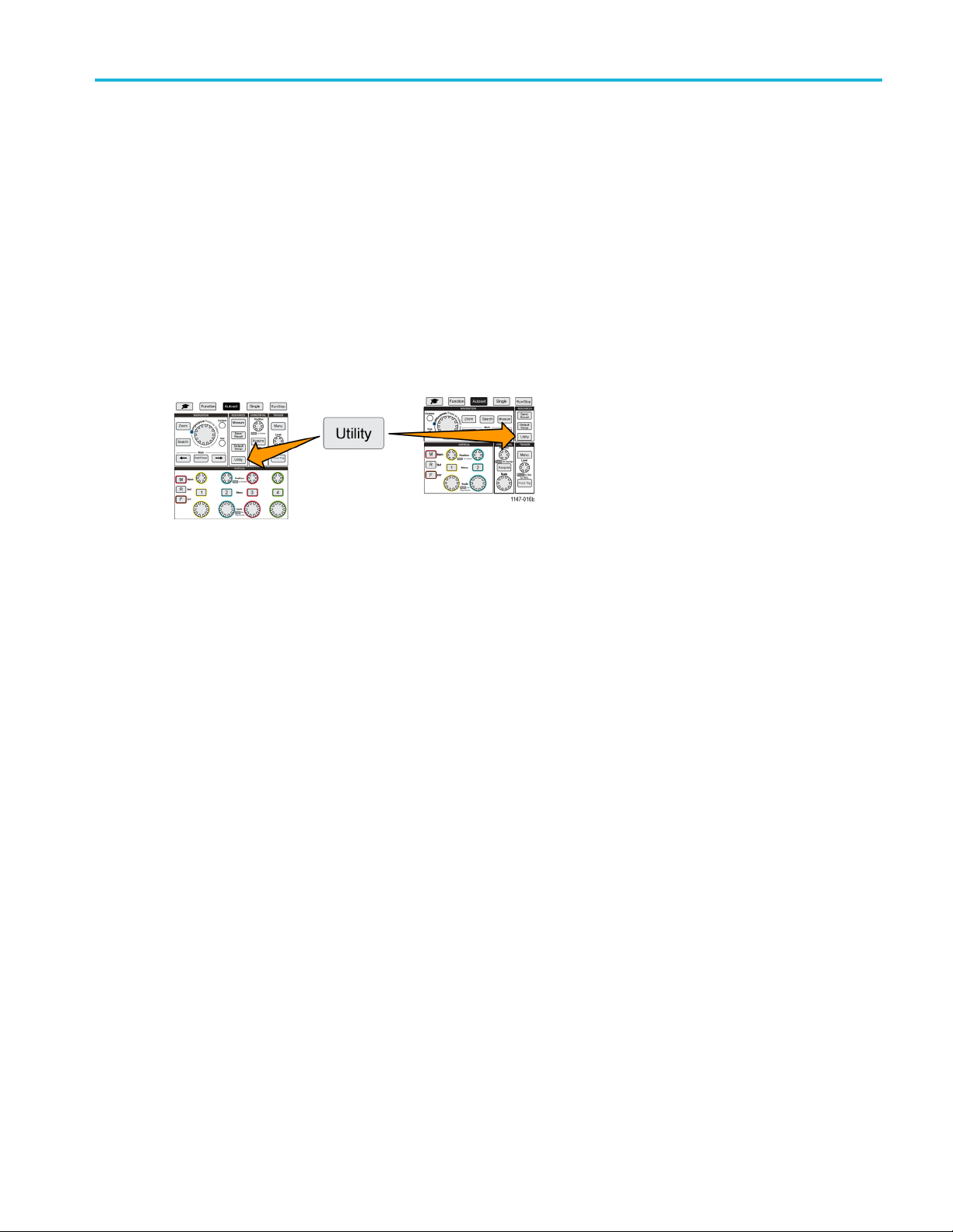
Setting up the LA
N network
Setting up the
The TBS2000 can connect to a LAN network to provide remote access to the instrument. Handy for classroom work,
remotely controlling the oscilloscope, remote monitoring and analysis of waveforms. Use the procedures in this section to
connect the oscilloscope to a network using a CAT5 Ethernet cable. A separate section covers configuring the oscilloscope
to connect to a Wi-Fi network. (See page 82, Setting up the Wi-Fi network.)
LAN network
Viewing the IP address - Ethernet
Use this procedure to see the oscilloscope IP address and related network settings. You may need the IP address
information to make a connection to the oscilloscope from a PC running on the network.
1. Push Utility front-panel button.
2. Push the Config side-menu button.
3. Use the Multipurpose knob to select and click Ethernet Config.
4. Select and click LAN Settings. The oscilloscope shows the IP address and other network-related settings. If no IP
address information is shown, and you need to set up the oscilloscope for network access, work with your network
administrator to determine how to get an IP address.
TBS2000 Series User Manual 79
Page 98
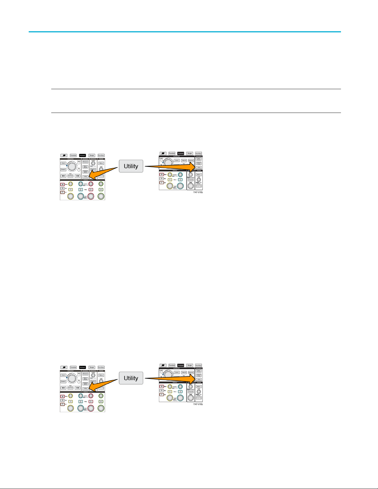
Setting up the LA
Nnetwork
Setting the IP address (DHCP network)- Ethernet
A Dynamic Host Configuration Protocol (DHCP) network automatically allocates network IP addresses and settings to
DHCP-enabled instruments like the TBS2000 Series oscilloscope. Use this procedure to turn DHCP-capability on and enable
the oscilloscope to obtain an IP address from the network DHCP server.
NOTE. DHCP-generated IP addresses can change each time the oscilloscope is powered on and requests an IP address
from the DHCP server. If the oscilloscope needs a permanent unchanging IP address, contact your system administrator to
obtain a permanent IP address and then add it manually to the oscilloscope.
Prerequisite: The oscilloscope must be connected to a DHCP-enabled network.
h Utility front-panel button.
1. Pus
2. Push the Config side-menu button.
3. Use the Multipurp ose knob to select and click Ethernet Config.
4. Highlight DHCP.
5. Push the Multipurpose knob to select ON. The oscilloscope takes a few moments to request and load the IP address
from the DHCP server. The LAN Test menu items should now show OK, and the network connection icon (upper
right edge of screen) should be on (white).
6. You c a n find out the IP address that was loaded into the oscilloscope. (See page 79, Viewing the IP address - Ethernet.)
Setting the IP address (nonDHCP network)- E thernet
If your network does not have Dynamic Host Configuration Protocol (DHCP) to automatically assign an IP address to the
oscilloscope, you must manually enter IP address and other network settings so that your oscilloscope can connect to a
network. Use this procedure to enter IP address and other network settings.
Prerequisite: Obtain the correct network settings from your system administrator (IP address, Subnet Mask, Default
Gateway, DNS IP address, and HTTP Port).
1. Push Utility front-panel button.
2. Push the Config side-menu button.
80 TBS2000 Series User Manual
Page 99

3. Use the Multipurpose knob to select and click Ethernet Config.
4. Select and click IP Addresses Settings. The oscilloscope opens the IP Addresses Settings dialog box.
5. Use the Multipurpose knob and side-menu buttons to enter the required network settings.
6. Push the OK side-menu button to enter the settings in the oscilloscope.
7. Confirm that the IP address was loaded into the oscilloscope. (See page 79, Viewing the IP address - Ethernet.)
8. Select and click the LAN Test menu item. The LAN Test menu should now show OK, and the network connection
icon (upper r
NOTE. If the LAN Test menu item shows No Response, work with your system administrator to confirm that the settings
that you were given are correct. Check that you entered the settings correctly.
ight edge of screen) should be on (white).
Turning Ethernet DHCP on or off
A Dynamic Host Configuration Protocol (DHCP) network automatically allocates network IP addresses and settings
to DHCP-enabled instruments like the TBS2000 Series oscilloscope. Use this procedure to turn the oscilloscope
DHCP-capability on or off.
1. Push Utility front-panel button.
Setting up the LA
N network
2. Push th
3. Use th
4. Highl
5. Push t
6. Push the knob again to turn DHCP Off.
e Config side-menu button.
e Multipurpose knob to select and click Ethernet Config.
ight DHCP.
he Multipurpose knob to select ON. The oscilloscope takes a few moments to request and load the IP address
form the DHCP server. The LAN Test menu items should now show OK, and the network connection icon (upper
right edge of screen) should be on (white).
TBS2000 Series User Manual 81
Page 100

Setting up the Wi
-Fi network
Setting up the
Connecting a Wi-Fi transceiver (dongle) to the rear USB Host port on your oscilloscope enables you to connect the
instrument to a Wi-Fi network. You can then use the Wi-Fi connection to access the oscilloscope from mobile devices
such as a smart phone or tablet, or from a PC.
This section covers configuring the oscilloscope to connect to a W i-Fi network. A separate section covers configuring the
oscilloscope to connect to a network using a CAT5 Ethernet cable. (See page 79, Setting up the LAN network.)
Wi-Fi network
Tu rning Wi-Fi on or off
You must turn on the Wi-Fi function before you can communicate with the oscilloscope. Use this procedure to turn on
or off Wi-Fi.
Prerequisites:
Connect a supported Wi-Fi dongle to the rear USB Host port (Tektronix option TEKUSBWIFI). Recommendation is to use
the rear US
DHCP conn
1. Push the U
B port so that you keep the front USB port available for saving and loading files.
ectivity is On.
tility front-panel button.
2. Push the Config side-menu button.
3. Use the Multipurpose knob to select and click Wi-Fi Config.
4. Highlight Wi-Fi On Off.
5. Push the Multipurpose knob to select ON. The oscilloscope takes a few moments to make the connection and request
and load the IP address from the network server. The Wi-Fi network connection icon (upper right edge of screen)
should be on (white).
6. Push the knob again to turn Wi-Fi to Off.
82 TBS2000 Series User Manual
 Loading...