

Page 1

www.keithley.com
Series 2200
Multichannel Programmable DC Power Supplies
Programming Technical Reference
2220S-907-01 Rev. B / Dec 2013
ECNEDIFNOCFOERUSAEMRETAERGA
Page 2

Page 3

Multichannel Programmable DC Power Supplies
Series 2200
Programming Technical Reference
© 2013, Keithley Instruments, Inc.
Cleveland, Ohio, U.S.A.
All rights reserved.
Any unauthorized reproduction, photocopy, or use the information herein, in whole or in part,
without the prior written approval of Keithley Instruments, Inc. is strictly prohibited.
All Keithley Instruments product names are trademarks or registered trademarks of Keithley
Instruments, Inc. Other brand names are trademarks or registered trademarks of their respective
holders.
Document number: 2220S-907-01 Rev. B / Dec 2013
Page 4

Safety precautions
The following safety precautions should be observed before using this product and an y associated instrumentation. Although
some instruments and accessories would normally be used with nonhazardous voltages, there are situations where hazardous
conditions may be present.
This product is intended for use by qualified personnel who recognize shock hazards and are familiar with the safety precautions
required to avoid possible injury. Read and follow all install a tion, operation, and maintenance information carefully before using
the product. Refer to the user documentation for complete product specifications.
If the product is used in a manner not specified, the protection provided by the product warranty may be impaired.
The types of product users are:
Responsible body is the individual or group responsible for the use and maintenance of equipment, for ensuring that the
equipment is operated within its specifications and operating limits, and for ensuring that operators are adequately trained.
Operators use the product for its intended function. They must be trained in electrical safety procedures and proper use of the
instrument. They must be protected from electric shock and contact with hazardous live circuits.
Maintenance personnel perform routine procedures on the product to keep it operating properly, for example, setting the line
voltage or replacing consumable materials. Maintenance procedures are described in the user documentation. The procedures
explicitly state if the operator may perform them. Otherwise, they should be performed only by service personnel.
Service personnel are trained to work on live circuits, perform safe installations, and repair products. Only properly trained
service personnel may perform installation and service procedures.
Keithley Instruments products are designed for use with electrical signals that are measurement, control, and data I/O
connections, with low transient overvoltages, and must not be directly connected to mains voltage or to voltage sources with high
transient overvoltages. Measurement Category II (as referenced in IEC 60664) connections require protection for high transient
overvoltages often associated with local AC mains connections. Certain Keithley measuring inst ruments may be connected to
mains. These instruments will be marked as category II or higher.
Unless explicitly allowed in the specifications, operating manual, and instrument labels, do not connect any instrument to mains.
Exercise extreme caution when a shock hazard is present. Lethal voltage may be present on cable connector jacks or test
fixtures. The American National Standards Institute (ANSI) states that a shock hazard exists when voltage levels greater than
30 V RMS, 42.4 V peak, or 60 VDC are present. A good safety practice is to expect that hazardous voltage is present in any
unknown circuit before measuring.
Operators of this product must be protected from electric shock at all times. The responsible body must ensure that operators
are prevented access and/or insulated from every connection point. In some cases, connections must be exposed to potential
human contact. Product operators in these circumstances must be trained to protect themselves from the risk of electric shock. If
the circuit is capable of operating at or above 1000 V, no conductive part of the circuit may be exposed.
Do not connect switching cards directly to unlimited power circuits. They are intended to be used with impedance-limited
sources. NEVER connect switching cards directly to AC mains. When connecting sources to switching cards, install protective
devices to limit fault current and voltage to the card.
Before operating an instrument, ensure that the line cord is connected to a properly-grounded power receptacle. Inspect the
connecting cables, test leads, and jumpers for possible wear, cracks, or breaks before each use.
When installing equipment where access to the main power cord is restricted, such as rack mounting, a separate main input
power disconnect device must be provided in close proximity to the equipment and within easy reach of the operator.
For maximum safety, do not touch the product, test cables, or any other instruments while power is applied to the circuit under
test. ALWAYS remove power from the entire test system and discharge any capacitors before: connecting or disconnecting
cables or jumpers, installing or removing switching cards, or making internal changes, such as installing or removing jumpers.
Do not touch any object that could provide a current path to the common side of the circuit under test or power line (earth)
ground. Always make measurements with dry hands while standing on a dry, insulated surface capable of withstanding the
voltage being measured.
Page 5

For safety, instruments and accessories must be used in accordance with the operating instructions. If the instruments or
accessories are used in a manner not specified in the operating instructions, the protection provided by the equipment may be
impaired.
Do not exceed the maximum signal levels of the instruments and accessories, as defined in the specifications and operating
information, and as shown on the instrument or test fixture panels, or switching card.
When fuses are used in a product, replace with the same type and rating for continued protection against fire hazard.
Chassis connections must only be used as shield connections for measuring circuits, NOT as protective earth (safety ground)
connections.
If you are using a test fixture, keep the lid closed while power is applied to the device under test. Safe operation requires the use
of a lid interlock.
screw is present, connect it to protective earth (safety ground) using the wire recommended in the user documentation.
If a
The
user documentation in all cases where the symbol is marked on the instrument.
The
contact with these voltages.
The symbol on an instrument shows that the surface may be hot. Avoid personal contact to prevent burns.
The
If this symbol is on a product, it indicates that mercury is present in the display lamp. Please note that the lamp must be
properly disposed of according to federal, state, and local laws.
The WARNING heading in the user documentation explains dangers that might result in personal injury or death. Always read
the associated information very carefully before performing the indicated procedure.
The CAUTION heading in the user documentation explains hazards that could damage the instrument. Such damage may
invalidate the warranty.
Instrumentation and accessories shall not be connected to humans.
Before performing any maintenance, disconnect the line cord and all test cables.
To maintain protection from electric shock and fire, replacement components in mains circuits — including the power
transformer, test leads, and input jacks — must be purchased from Keithley Instruments. Standard fuses with applicable national
safety approvals may be used if the rating and type are the same. Other components that are not safety-related may be
purchased from other suppliers as long as they are equivalent to the original component (note that selected parts should be
purchased only through Keithley Instruments to maintain accuracy and functionality of the product). If yo u are unsure about the
applicability of a replacement component, call a Keithley Instruments office for information.
symbol on an instrument means caution, risk of danger. The user must refer to the operating instructions located in the
symbol on an instrument means caution, risk of electric shock. Use standard safety precautions to avoid personal
symbol indicates a connection terminal to the equipment frame.
To clean an instrument, use a damp cloth or mild, water-based cleaner. Clean the exterior of the instrument only. Do n ot app ly
cleaner directly to the instrument or allow liquids to enter or spill on the instrument. Products that consist of a circuit board with
no case or chassis (e.g., a data acquisition board for installation into a computer) should never require cleaning if handled
according to instructions. If the board becomes contaminated and operation is affected, the board should be returned to the
factory for proper cleaning/servicing.
Safety precaution revision of January 2013.
ii
-907-01 Rev. B/December 2013
2220S
Page 6

Page 7

Table of Contents
Preface .............................................................................................................. iii
Welcome ........................... ................................ .................................. .......... iii
Products.............................. .................................. ................................ ........ iii
Extended Warranty ....................... ................................ ................................ .... iv
Contact Information .......................................................................................... iv
Getting Started
Getting Started ... . .. .. .. .. .. .. .. .. .. .. . .. .. .. .. .. .. .. .. .. .. .. .. .. . .. .. .. .. .. .. .. .. .. .. .. . .. .. .. .. .. .. .. .. .. .. .. .. . 1-1
Using the USB interface .................................................................................... 1-1
Using the GPIB interface ................................ .................................. ................. 1-1
Command Timing........................................... ................................ ................. 1-2
Command Syntax.... ................................ ................................ ............................. 2-1
Command and Query Structure ............................................................................ 2-1
Command Entry.............................................................................................. 2-3
and Groups ................................................................................................ 2-7
Comm
Status Commands............................................................................................ 2-7
Save and Recall Commands ................................................................................ 2-8
System Commands ........................... ................................ ............................... 2-9
Diagnostic Commands ...................................................................................... 2-9
Synchronization Commands............................... ................................ ................. 2-9
Trigger Commands ... ................................ ................................ ..................... 2-10
Measurement Commands ................................................................................. 2-11
Source Commands........................ ................................ ................................ . 2-11
Channel Combination Commands ....................................................................... 2-12
Display Commands ........................................................................................ 2-12
Commands Listed in Alphabetical Order ................... .................................. ............... 2-13
Status and Events
Status and Events ................................................................................................. 3-1
Status Reporting Structure.................................................................................. 3-1
Registers ......... ................................ .................................. ........................... 3-3
Queues ........................................................................................................ 3-9
Messages and Codes.................... ................................ .................................. . 3-10
Series 2200 Programmable Multichannel DC Power Supplies Programmer Manual i
Page 8

Table of Contents
Appendices
Appendix A: ASCII Code Chart ............................................................................... A-1
Appendix B: Programming Examples......................................................................... B-1
Appendix C: Default Setup..................................................................................... C-1
ii Series 2200 Programmable Multichannel DC Power Supplies Programmer Manual
Page 9

Preface
Welcome
Thank you for using a Keithley Instruments product. The Series 2200
Multichannel Programmable DC Power Supplies are flexible DC sources designed
to power a wi
offer three power channels and the model 2220-30-1 and its variants provide two
channels. The output channels on both models are independent and isolated,
allowing you to power circuits with different references or polarities. Each
channel can be enabled or disabled as your application requires. All outputs
feature remote sense capability which can be used to reduce the effect of lead
resistan
Basic current accuracy is 0.1% for all channels and linear regulation delivers
low noise – less than 3 mVp-p. Flexible display modes make it easy to use the
two 30 V outputs in combination, and the USB interface makes it easy to build
PC-based systems without converters or special cables. The G versions of each
model include a GPIB interface in combination with the USB interface.
These compact power supplies cover a wide range of applications without
covering a lot of bench space. Versions of these power supplies are available for
t 100 VAC nominal line voltage which is common in Japan. These versions
use a
are indicated by the "J" suffix.
de range of applications. The model 2230-30-1 and its variants
ce, delivering 0.03% basic voltage accuracy even when using long leads.
Products
This manual contains information about the following products:
ModelDescription
2220-30-1
Programmable Dual Channel DC Power Supply
2220G-30-1Programmable Dual Channel DC Power Supply with GPIB Interface
2220J-30-1
Programmable Dual Channel DC Power Supply for Japan
2220GJ-30-1Programmable Dual Channel DC Power Supply with GPIB Interface for Japan
2230-30-1
Triple Channel Programmable DC Power Supply
2230G-30-1Programmable Triple Channel DC Power Supply with GPIB Interface
2230J-30-1
Triple Channel Programmable DC Power Supply for Japan
2230GJ-30-1Programmable Triple Channel DC Power Supply with GPIB Interface for Japan
Series 2200 Programmable Multichannel DC Power Supplies Programmer Manual iii
Page 10

Preface
Extended Warranty
Contact Information
Additional years of warranty coverage are available on many products. These
valuable contracts protect you from unbudgeted service expenses and provide
additional years of protection at a fraction of the price of a repair. Extended
warranties are available on new and existing products. Contact your local Keithley
Instrument
s representative for details.
If you have
following sources:
1. Keithley
2. Keithley web forum (http://forum.keithley.com)
3. Call Keithley Instruments corporate headquarters (toll-free inside the U.S. and
Canada only) at 1-888-KEITHLEY (1-888-534-8453), or from outside the
U.S. at
Instruments website (http://www.keithley.com).
any questions after reviewing this information, please use the
Instruments website (http://www.keithley.com)
+1-440-248-0400. For worldwide contact numbers, visit the Keithley
iv Series 2200 Programmable Multichannel DC Power Supplies Programmer Manual
Page 11

Getting Started
Page 12

Page 13

Getting Started
Using the USB interface
Your power supply has a USB 2.0 high-speed device port to control the power
supply using the USBTMC protocol. The USBTMC protocol allows USB devices
to communica
If you have a G-version, you can also remotely communicate between your power
supply and PC over GPIB.
Start by connecting an appropriate USB cable between the USB 2.0 high-speed
device port on the rear panel of your power supply and a PC.
In order for the PC to recognize the power supply, a USBTMC driver must be
installed on the PC. A USBTMC driver can be installed on your PC by installing
a virtual instrument communications API like NIVISA. This VISA is available
for download from the Keithley or National Instruments Web sites. Once the
USBTMC driver is loaded, your PC will establish communication with the power
supply upon USB cable connection.
For further remote control and/or programming use, other software applications
may be needed in addition to a
te using IEEE-488.2 style messages.
VISA and the USBTMC driver.
Using the GPIB interface
Start by connecting an appropriate GPIB cable between the power supply and
either a PC or another instrument with a GPIB interface if the power supply is
in a multi-instrument system.
It is recommended that NIVISA be installed on your PC for the GPIB interface
for maximum programming flexibility.
To change GPIB address
settings
Your power supply must have a unique device address to function properly.
The default setting for the GPIB configuration is Communication Address 1.
If there is more than one GPIB instrument on the bus, you will need to change
the default setting on the power supply. To change the GPIB address settings,
do the following:
1. Push the Menu button on the instrument front-panel to access the main menu.
2. Press the up arrow key until you see User Settings andthenpresstheEnter
3. Press the up or down arrow key until you see Communication Port and
4. You can now change the address of your GPIB port.
button.
then press the Enter button.
Series 2200 Programmable Multichannel DC Power Supplies Programmer Manual 1-1
Page 14

Getting Started
Command Timing
The power suppl
controller.
The average time it takes to both send and receive every command is
approximately 20 ms. In the case of more complex commands, more time may
be required to complete transmission.
y is now set up for bidirectional communication with your
1-2 Series 2200 Programmable Multichannel DC Power Supplies Programmer Manual
Page 15

Command Syntax
You can control the power supply through the USB interface or the GPIB interface
(G-version instruments only) using commands and queries.
This section describes the syntax these commands and queries use and the
conventions the power supply uses to process them. The commands and queries
themselves
Groups.)
are listed by group and alphabetically. (See page 2-7, Command
You tra ns m
Standard Code for Information Interchange (ASCII) character encoding. Appendix
A contains a chart of the ASCII character set.
The Backus Naur Form (BNF) notation is used in this manual to describe
commands and queries. (See Table 2-1.)
Table 2-1: BNF notation
Symbol Meaning
<>
::=
| Exclusive OR
{ } Group; one element is required
[]
.. .
( ) Comment
Command and Query Structure
Commands consist of set commands and query commands (usually simply called
commands and queries). Commands change power supply settings or perform a
specific action. Queries cause the power supply to return data and information
about its status.
it commands to the power supply using the enhanced American
Defined element
Is defined as
Optional; can be omitted
Previous element(s) may be repeated
Most commands have both a set form and a query form. The query form of the
command is the same as the set form except that it ends with a question mark.
For example, the set command STATus:OPERation:ENAble has a query form
STATus:OPERation:ENAble?. Not all commandshavebothasetandaquery
form; some commands are set only and some are query only.
A command message is a command or query name, followed by any information
the power supply needs to execute the command or query. Command messages
consist of five different element types. (See Table 2-3.)
Series 2200 Programmable Multichannel DC Power Supplies Programmer Manual 2-1
Page 16

Command Syntax
Table 2-2: Comm
Symbol Meaning
<Header>
<Mnemonic>
<Argument
<Comma> A single c
<Space>
>
and message elements
The basic command name. If the header ends with a question mark,
the command is a query. The header may begin with a colon (:)
character; i
beginning colon is required. The beginning colon can never be used
with command headers beginning with a star (*).
A header subfunction. Some command headers have only one
mnemonic. I
always separated from each other by a colon (:) character.
A quantity
Not all commands have an argument, while other commands have
multiple arguments. Arguments are separated from the header by a
<Space>. A
It may optionally have white space characters before and after the
comma.
A white space character between command header and argument. It
may optionally consist of multiple white space characters.
f the command is concatenated with other commands the
f a command header has multiple mnemonics, they are
, quality, restriction, or limit associated with the header.
rguments are separated from each other by a <Comma>.
omma between arguments of m ultiple-argument commands.
The following figure shows the five command message elements.
Commands
Queries
Figure 2-1: Command message elements
Commands cause the power supply to perform a specific function or change one
of its settings. Commands have the structure:
[:]<Header>[<Space><Argument>[<Comma><Argument>]...]
A command header is made up of one or more mnemonics arranged in a
hierarchical or tree structure. The first mnemonic is the base or root of the tree
and each subsequent mnemonic is a level or branch off of the previous one.
Commands at a higher level in the tree may affect those at a lower level. The
leading colon (:) always returns you to the base of the command tree.
Queries cause the power supply to return information about its status or settings.
Queries have the structure:
[:]<Header>
[:]<Header>[<Space><Argument>[<Comma><Argument>]...]
2-2 Series 2200 Programmable Multichannel DC Power Supplies Programmer Manual
Page 17

Command Syntax
Query Responses
Command Entry
You can specify
a query command at any level within the command tree unless
otherwise noted. These branch queries return information about all the mnemonics
below the specified branch or level.
When a query is sent to the power supply, only the values are returned. When
the returned value is a mnemonic, it is noted in abbreviated format, as shown
in the following table.
Table 2-3: Query response examples
Query Response
MEASure:VOLTage:DC?
SOURce:FUNCtion:MODE?
5.0011
LIST
Follow these general rules when entering commands:
Enter commands in upper or lower case.
You can precede any command with white space characters. White space
characters include any combination of the ASCII control characters 00 through
09 and 0B through 20 hexadecimal (0 through 9 and 11 through 32 decimal).
SCPI Commands and
Queries
The power supply ignores commands that consists of just a combination of
white space characters and line feeds.
The power supply uses a command language based on the SCPI standard. The
SCPI (Standard Commands for Programmable Instruments) standard was created
by a consortium to provide guidelines for remote programming of instruments.
These guidelines provide a consistent programming environment for instrument
control and data transfer. This environment uses defined programming messages,
instrument responses and data formats that operate across all SCPI instruments,
regardless of manufacturer.
The SCPI language is based on a hierarchical or tree structure that represents a
subsystem. The top level of the tree is the root node; it is followed by one or more
lower-level nodes. (See Figure 2-2.)
Figure 2-2: Example of SCPI subsystem hierarchy tree
Series 2200 Programmable Multichannel DC Power Supplies Programmer Manual 2-3
Page 18

Command Syntax
Message Terminators
Parameter types
You can create c
ommands and queries from these subsystem hierarchy trees.
Commands specify actions for the instrument to perform. Queries return
measurement data and information about parameter settings.
This manual u
ses the term <EOM> (End of message) to represent a message
terminator.
USB End of Message (EOM) terminators. See the USB Test a nd Measurement
Class Specification (USBTMC) section 3.2.1 for details. The power supply
terminates messages by setting the EOM bit in the USB header of the last
transfer
of a message to the host (USBTMC Specification section 3.3.1), and by
terminating messages with a LF.
When rec
eiving, the power supply expects a LF and an asserted EOM bit as a
message terminator. When using the GPIB interface, the power supply expects a
line feed (LF) as the message terminator.
Many po
wer supply commands require parameters. Parameters are indicated
by angle brackets, such as <file_name>. There are several different types of
parameters, as listed in the following table. The parameter type is listed after the
parameter. Some parameter types are defined specifically for the power supply
command set and some are defined by SCPI. (See Table 2-4.)
Table 2-4: Types of parameters
Parameter type Description Example
boolean Boolean numbers or values ON or ≠ 0
OFF or 0
discrete
NR1 numeric Integers 0, 1, 15, -1
NR2 numeric Decimal numbers 1.2, 3.141516, -6.5
NR3 numeric Floating point numbers 3.1415E-9, -16.1E5
NRf numeric
string
A list of specific values
Flexible decimal number that
maybetypeNR1,NR2,orNR3
Alphanumeric characters (must
be within quotation marks)
MIN, MAX
See NR1, NR2, NR3 examples in
this table
“Testing 1, 2, 3”
2-4 Series 2200 Programmable Multichannel DC Power Supplies Programmer Manual
Page 19

Command Syntax
Abbreviating Commands,
Queries, and Parameters
Chaining Commands and
Queries
You can abbrevi
short form. This manual shows these commands as a combination of upper and
lower case letters. The upper case letters indicate the accepted short form of a
command, as shown in the following figure. The accepted short form and the long
form are equivalent and reques t the same action of the instrument.
Figure 2-3: Example of abbreviating a command
You can chain several commands or queries together into a single message. To
create a chained message, first create a command or q
(;), and finally add more commands or queries and semicolons until you are done.
If the command following a semicolon is a root node, precede it with a colon
(:). The following figure illustrates a chained message consisting of several
commands and queries. The chained message should end in a command or query,
not a semicolon. Responses to any queries i n your message are separated by
semicolons.
ate most SCPI commands, queries, and parameters to an accepted
uery, then add a semicolon
Figure 2-4: Example of chaining commands and queries
If a command or query has the same root and lower-level nodes as the previous
command or query, you can omit these nodes. In the following figure, the second
command has the same root node (STAT:QUES) as the first command, so these
nodes can be omitted.
Figure 2-5: Example of omitting root and lower level nodes
Series 2200 Programmable Multichannel DC Power Supplies Programmer Manual 2-5
Page 20

Command Syntax
General Rules for Using
SCPI Commands
The following a
re three general rules for using SCPI commands, queries, and
parameters:
You c an us e s in
gle (‘ ’) or double (“ ”) quotation marks for quoted strings, b ut
you cannot use both types of quotation marks for the same string.
correct
correct
incorrect “This strin
“This string uses quotation marks correctly.”
‘This string also uses quotation marks correctly.’
g does not use quotation marks correctly.’
You can use upper case, lower case, or a mixture of both cases for all
commands, queries, and parameters.
:SOURCE:FREQUENCY 10MHZ
is the same as
:source:frequency 10mhz
and
:SOURCE:frequency 10MHZ
NOTE. Q
uoted strings are case sensitive.
No embedded spaces are allowed between or within nodes.
correct
incorrect
:OUTPUT:FILTER:LPASS:FREQUENCY 200MHZ
:OUTPUT: FILTER: LPASS:FREQUENCY 200MHZ
2-6 Series 2200 Programmable Multichannel DC Power Supplies Programmer Manual
Page 21

Command Groups
This manual lists the power supply commands in two ways. First, it presents
them by functional groups. Then, it lists them alphabetically. The functional
group list st
(See page 2-13.)
The power supply interface conforms to Keithley standard codes and formats
except where noted. The GPIB interface also conforms to IEEE Std 488.2–1987
except where noted. The USB interface also conforms to USB Test and
Measurement Class, Subclass USB488 Specification, except where noted.
Arguments are not mentioned in the group command descriptions, but are listed
under the commands in the Commands Listed in Alphabetical Order section of
this manual. (See page 2 -13.)
Status Commands
Status commands let you determine the status of the power supply and control
events.
Several commands and queries are common to all devices on the GPIB or USB
bus. These commands and queries are defined by IEEE Std. 488.2-1987 and Tek
Standard Codes and Formats 1989, and begin with an asterisk (*) character.
arts below. The alphabetical list provides detail on each command.
Table 2-5: Status commands
Command Description
*CLS Clear all event registers and queues.
*ESE Set/query standard event status enable register.
*ESR?
*IDN? Return identification information in IEEE 488.2 notation.
*RST
*PSC Set/query power-on status clear.
*SRE Set/query service request enable register.
*STB?
STATus:QUEStionable:INSTrument[:EVENt]?
STATus:QUEStionable:INSTrument:ENABle Set/query questionable enable register. This parameter
STATus:QUESTionable:INSTrument:ISUMmary<x>:[EVENt]? Return questionable event register summary for channel x,
STATus:QUEStionable:INSTrument:ISUMmary<x>:ENABle Set/query questionable enable register summary for channel x,
Return standard event status register.
Resets to known settings, but does not purge stored settings.
Read status byte.
Return questionable event register.
determines which bit of the quest event register is set to 1. If a
QUES condition changes, the QUES bit of status byte register
will be set to 1.
where <x> is 1, 2, or 3.
where <x> is 1, 2, or 3. This parameter determines which bit of
the quest event register is set to 1. If a QUES condition changes,
the QUES bit of status byte register will be set to x.
Series 2200 Programmable Multichannel DC Power Supplies Programmer Manual 2-7
Page 22

Command Groups
Table2-5:Statuscommands(cont.)
Command Description
STATus:QUEStionable:INSTrument:ISUMmary<x>:CONDition? Return questionable condition register summary for channel
x, where <x> is 1, 2, or 3. When a bit of the quest condition
changes, the corresponding bit value in the quest event register
will be set to x.
STATus:QUEStionable:ENABle Set/query questionable enable register. This parameter
determines which bit of the quest event register is set to 1. If a
QUES condition changes, the QUES bit of status byte register
will be set to 1.
STATus:QUEStionable[:EVENt]?
STATus:OPERation:INSTrument[:ENABle]? Set/query operation enable register. The parameter determines
STATus:OPERation:INSTrument[:EVENt]?
STATus:OPERation:INSTrument[:EVENt]? Queries the contents of the operation instrument event register
STATus:OPERation:INSTrument[:ENABle]? Queries the contents of the operation instrument enable register
STATus:OPERation:INSTrument:ISUmmary<x>[:EVENt]? Return operation event register for channel x, where <x> is 1,
STATus:OPERation:INSTrument:ISUmmary<x>:ENABle Set/query operation enable register for channel x, where <x> is
STATus:OPERation:INSTrument:ISUMmary<x>:CONDition? Return operation condition register for channel x, where <x> is
Return questionable event register.
which bit value of quest event register is set to 1. If a OPER
condition changes, the OPER bit of the status byte register will
be set to 1.
Return operation event register.
(OIEVR).
(OIENR).
2, or 3.
1, 2, or 3. The parameter determines which bit value of quest
event register is set to 1. If a OPER condition changes, the
OPER bit of the status byte register will be set to 1.
1, 2, or 3. When a parameter of the operation condition register
changes, the corresponding bit in the operation event register
will be set to 1.
Save and Recall Commands
Save and recall commands allow you to save the active settings to one of the
settings memories within the power supply, and recall those settings at a later time.
Table 2-6: Save and recall commands
Header Description
*SAV Save instrument setting to setup memory
*RCL Recall instrument setting from setup memory
2-8 Series 2200 Programmable Multichannel DC Power Supplies Programmer Manual
Page 23

Command Groups
System Comman
Table 2-7: System commands
Header Description
SYSTem:POSetup Set or query power-on parameters
SYSTem:MODUle? Queries the module of the power supply
SYSTem:VERSion? Return SCPI version information
SYSTem:MODUle? Return error code and error information
SYSTem:KEY Set or query key operation
SYSTem:REMote Set or query remote mode
SYSTem:RWLock Set to remote mode and lock front-panel
SYSTem:LOCal Set to front-panel control mode
ds
Diagnostic Commands
The po
is functioning as expected. A table of error codes that may be returned by the self
test are given in the Messages and Codes section. (See page 3-10.)
Table 2-8: Diagnostic commands
wer supply includes a self test function that may be used to confirm that it
Header Description
*TST? Perform self-test and return result status
Synchronization Commands
Table 2-9: Synchronization commands
Header Description
*OPC Set/query operation complete
*WAI
Wait to continue
Series 2200 Programmable Multichannel DC Power Supplies Programmer Manual 2-9
Page 24

Command Groups
Trigger Comma
Table 2-10: Trigger commands
Header Description
TRIGger[:IMMediate]
*TRG Generates a trigger event.
[SOURce:]VOLTage:TRIGgered[:IMMediate] Set or query the trigger voltage.
[SOURce:]CURRent:TRIGgered[:IMMediate] Set or query the trigger current.
INSTrument:COUPle[:TRIGger] Set or query the channel that will respond the trigger command.
nds
Trigger commands are used to determine the timing of list mode sequences.
Forces an immediate trigger event.
2-10 Series 2200 Programmable Multichannel DC Power Supplies Programmer Manual
Page 25

Command Groups
Measurement C
ommands
Measurement commands are used to query parameters. The MEASure commands
initiate and execute a complete measurement cycle and are recommended for
measuring vo
ltage and current at the outputs of the power supply.
FETCh
commands do not initiate a new measurement cycle but rely on measurements
stored in the communication buffers of the power supply. The
FETCh commands
are provided for voltage and current measurements to maintain compatibility
with other instruments. Output power, however, is only available using a
command.
Table 2-11: Measurement commands
Command Description
MEASure[:SCALar][:VOLTage][:DC]?
MEASure[:SCALar]:POWer[:DC]?
MEASure[:SCALar]:CURRent[:DC]?
FETCh[:SCALar]:CURRent[:DC]? Query the output current stored in the communications buffer
FETCh[:SCALar]:POWer[:DC]? Query the output power stored in the communications buffer
FETCh[:SCALar]:VOLTage[:DC]? Query the output voltage stored in the communications buffer
Initiate a measurement and query the measured output voltage
Initiate a measurement and query the measured output current
Initiate a measurement and query the measured output current
FETCh
Source Commands
These commands allow you to set various output parameters. Some of the
commands are used to configure protection functions like output timers and Max
Voltage.
Table 2-12: Source commands
Command Description
[SOURce:]CURRent[:LEVel][:IMMediate][:AMPLitude] Set or query the current value in units of A or mA.
[SOURce:]CURRent[:LEVel]:UP[:IMMediate][:AMPLitude] Set the current level to increase a step.
[SOURce:]CURRent[:LEVel]:DOWN[:IMMediate][:AMPLitude] Set the current level to decrease a step.
[SOURce:]CURRent[:LEVel][:IMMediate]:STEP[:INCRement] Set or query the current step value.
[SOURce:]OUTPut:TIMer[:STATe] Set or query the state of the output timer.
[SOURce:]OUTPut[:STATe][:ALL] Set or query power supply output on or off.
[SOURce:]OUTPut:TIMer:DELay Set or query the time duration of output timer.
[SOURce:]VOLTage[:LEVel][IMMediate][:AMPLitude] Set or query voltage level.
[SOURce:]VOLTage[:LEVel]:UP[:IMMediate][:AMPLitude] Set to increase the voltage level by a step.
[SOURce:]VOLTage[:LEVel]:DOWN[:IMMediate][:AMPLitude] Set to decrease the voltage level by a step.
[SOURce:]VOLTage[:LEVel][:IMMediate]:STEP[:INCRement] Set or query the voltage step value.
[SOURce:]VOLTage:LIMit:STATe Set or query enable/disable voltage limit function.
[SOURce:]VOLTage:LIMit[:LEVel] Set or query the maximum output voltage setting.
Series 2200 Programmable Multichannel DC Power Supplies Programmer Manual 2-11
Page 26

Command Groups
Table 2-12: Source commands (cont.)
Command Description
[SOURce:]OUTPut:ENABle Set or query the current channel as enabled or disabled.
[SOURce]:CHANnel:OUTPut:[STATe] Set or query the output status of the current channel.
[SOURce:]APPly Sets voltage and current level and switch channels at the same
time.
[SOURce:]OUTPut:PARallel[:STATe] Sets the parallel state of CH1 and CH2.
[SOURce:]OUTPut:SERies Sets the serial state of CH1 and CH2.
[SOURce:]OUTPut:PON[:STATe] Sets the power supply to power up with its output turned off, or to
return the output to the state it was in when it powered down.
Channel Combination Commands
These commands allow you to set various channel combinations. The commands
n use depends on the number of channels your instrument has.
you ca
Table 2-13: Channel combination commands
Command Description
INSTrument:SELect Switch or query the current channel.
INSTrument:COMbine:SERies Set CH1 and CH2 in series.
INSTrument:COMbine:PARAllel Set CH1 and CH2 in parallel.
INSTrument:COMbine:TRACk Set CH1 and CH2 to track.
INSTrument:COMbine:OFF Remove the combination of channels.
INSTrument:COMbine? Query which channels are combined.
Display Commands
Display commands are used to clear of show particular strings on the instrument
display.
Table 2-14: Display commands
Header Description
DISPlay[:WINDow][:STATe] Set or query the display state.
DISPlay[:WINDow]:TEXT[:DATA] Set or query the display to show a particular string.
DISPlay[:WINDow]:TEXT:CLEar Set to clear the characters on the display and returns the display
to normal mode.
2-12 Series 2200 Programmable Multichannel DC Power Supplies Programmer Manual
Page 27

Commands Listed in Alphabetical Order
You can use commands to either set instrument features or query instrument
values. You can use some commands to do both, some only to set and some only
to query. Thi
Form” included with the command name. It marks query-only commands with
a question mark appended to the header, and includes the words “Query Only”
in the command name.
This document spells out headers, mnemonics, and arguments with the minimal
spelling shown in uppercase. For example, to use the abbreviated form of the
MEASure:SCALar:VOLTage:DC? command, type MEAS:S CAL:VOLT:DC?.
*CLS (No Query Form)
s document marks set-only commands with the words “No Query
The *CLS
Group
Syntax
Related Commands
Status
*CLS
*ESR?, *STB?
DISPlay[:WINDow][:STATe]
Sets or queries the state of the instrument display.
Group
Syntax
Arguments
Display
DISPlay[:WINDow][:STATe] {0|1 |ON|OFF}
DISPlay[:WINDow][:STATe]?
0|1|ON|OFF
command clears all event registers and queues.
DISPlay[:WINDow]:TEXT[:DATA]
Sets or queries the state of the instrument display to show a particular string.
Group
Series 2200 Programmable Multichannel DC Power Supplies Programmer Manual 2-13
Display
Page 28

Commands Listed in Alphabetical Order
Syntax
Arguments
DISPlay[:WIND
DISPlay[:WINDow]:TEXT[:DATA]?
String with quotes. 48 character length limit.
ow]:TEXT[:DATA] <string>
DISPlay[:WINDow]:TEXT:CLEar (No Query Form)
Clears the characters on the display and then returns the display to normal m ode.
Group
Syntax
Arguments
Display
DISPlay[:WINDow]:TEXT:CLEar
None
*ESE
Sets and queries the bits in the Event Status Enable Register (ESER). The ESER
is an eight-bit mask register that determines which bits in the Standard Event
Status Register (SESR) will set the ESB bit in the Status Byte Register (SBR).
(See page 3-1, Status and Events.)
Group
Syntax
Related Commands
Arguments
Examples
Status
*ESE <mask>
*ESE?
*CLS, *ESR?
<mask>::=<NR1> where:
<NR1> is a value in the range from 0 through 255
are set according to this value.
The power-on default for ESER is 0 if *PSC is 1. If *PSC is 0, the ESER
maintains its value through a power cycle.
*ESE 145 sets the ESER to binary 10010001, which enables the PON, EXE,
and OPC bits.
. The binary bits of the ESER
2-14 Series 2200 Programmable Multichannel DC Power Supplies Programmer Manual
Page 29

Commands Listed in Alphabetical Order
*ESR? (Query Only)
Group
Syntax
Related Commands
Returns
*ESE might retu
binary value 10111010.
Returns the contents of the Standard Event Status Register (SESR). *ESR? also
clears the SESR (since reading the SESR clears it). (See page 3-1, Status and
Events.)
Status
*ESR?
*CLS, *OPC, *SRE,
<NR1>, which is a decimal representation of the contents of the Standard Event
Status Register (SESR).
rn the string
*ESE 186, showing that the ESER contains the
FETCh[:SCAL
Related Commands
Examples
*ESR? might return the value 149, showing that the SESR contains binary
10010101.
ar]:CURRent[:DC]? (Query Only)
This command returns the last measured output current stored in the
communications buffer of the power supply. A new measurement is not initiated
and.
Group
Syntax
by this comm
CAUTION. Using this FETCh c ommand may return an old result, which could
adversely affect the accuracy of your test. In most cases, using the MEASure
command is recommended. The benefit of the FETCh command is that it provides
a result a bit more quickly than the MEASure command.
Measurement
FETCh[:SCALar]:CURRent[:DC]? [CH1|CH2|CH3|ALL]
MEASure[:SCALar]:POWer[:DC]?
Series 2200 Programmable Multichannel DC Power Supplies Programmer Manual 2-15
Page 30

Commands Listed in Alphabetical Order
Returns
Examples
<NR2>, which gi
FETC:CURR? might return 0.09998, which would be the current measured at the
output of the power supply in amperes.
ves is the measured output current in amperes.
FETCh[:SCALar]:VOLTage[:DC]? (Query Only)
This command returns the last measured output voltage stored in the
communications buffer of the power supply. A new measurement is not initiated
by this command.
Group
Syntax
Related Commands
Returns
Measurement
FETCh[:SCALar]:VOLTage[:DC]? [CH1|CH2|CH3|ALL]
MEASure[:SCALar][:VOLTage][:DC]?
<NR2> is the measured output voltage in volts.
Examples
FETC:VOLT? might return 5.0011, which would be the measured voltage across
the power supply outputs in volts.
FETCh[:SCALar]:POWer[:DC]? (Query Only)
This command returns the calculated power based on the last measured output
voltage and current. A new measurement is not initiated by this command. The
power calculation in the instrument is performed approximately every 100 ms.
Insure that the voltage and current are stable longer than this for good results.
Group
Syntax
Returns
Examples
Measurement
FETCh[:SCALar]:POWer[:DC]? [ CH1|CH2|CH3|ALL]
<NR2> is the measured output power in watts.
FETCh:POW? might return 6.01667, which would be the power measured at the
output of t he power supply in watts.
2-16 Series 2200 Programmable Multichannel DC Power Supplies Programmer Manual
Page 31

Commands Listed in Alphabetical Order
*IDN? (Query O
<manufacturer> <model> <serial number> <firmware_version>
keithley 22XXX XXXXXX X. XX-X. XX
nly)
Group
Syntax
Returns
Examples
Returns the power supply identification code in IEEE 488.2 notation.
Status
*IDN?
A string that includes <manufacturer>, <model>, <serial number>, and
<firmware_version> as defined in the following table.
*IDN?
might return the following response for a 2220-30-1:
KEITHLEY , 2220-30–1 , 000004 , 1.01–1.20
INSTrument:COMbine? (Query Only)
This command queries the instrument to det
channels 1 and 2.
Group
Syntax
Related Commands
Returns
Channel
INSTrument:COMbine?
INSTrument:COMbine:OFF
Series for series combination.
Parallel for parallel combination.
NONE for combination off.
INSTrument:COMbine:OFF
This command is used to turn off series, parallel, or tracking mode, and return
channels 1 and 2 to independent operation.
ermine the combination state of
Series 2200 Programmable Multichannel DC Power Supplies Programmer Manual 2-17
Page 32

Commands Listed in Alphabetical Order
Group
Syntax
Related Commands
Examples
Instrument
INSTrument:COMbine:OFF
INSTrument:COMbine?
INSTRUMENT:COMBINE:OFF
INSTrument:COMbine:PARAllel (No Query Form)
This command sets CH1 and CH2 into parallel mode. This mode assumes that
CH1 and CH2 have been wired in parallel external to the power supply. The
combined channel should be referred to as CH1 and the current for the combined
channel may be set as high as 3A. Voltage will be set to the same value for both
Group
channels. The
current.
Channel
measure:current command will respond with the combined
Syntax
Related Commands
Examples
INSTrument:COMbine:PARAllel
INSTrument:COMbine:OFF, INSTrument:COMbine:SERies, INSTrument:
COMbine:TRACk,
INSTRUMENT:COMBINE:PARALLEL
INSTrument:COMbine:SERies (No Query Form)
This command sets CH1 and CH2 into series mode. This mode assumes that CH1
and CH2 have been wired in series external to the power supply. The combined
channel should be referred to as CH1 and the voltage for the combined channel
may be set as high as 60 V. The current limit will be set to the same value for both
Group
Syntax
channels. The
voltage.
Channel
INSTrument:COMbine:SERies
measure:voltage command will respond with the combined
2-18 Series 2200 Programmable Multichannel DC Power Supplies Programmer Manual
Page 33

Commands Listed in Alphabetical Order
Related Commands
Examples
INSTrument:CO
INSTrument:COMbine:TRACk
INSTRUMENT:COMBINE:SERIES
Mbine:OFF, INSTrument:COMbine:PARAllel,
INSTrument:COMbine:TRACk (No Query Form)
This command sets CH1 and CH2 in track mode. In this mode, the ratio of CH1
to CH2 voltage that is set before sending the command will be maintained for
subsequent voltage settings.
Group
Syntax
Related Commands
Channel
INSTrument:COMbine:TRACk
INSTrument:COMbine:OFF, INSTrument:COMbine:PARAllel,
INSTrument:COMbine:SERies
Examples
INSTRUMENT:COMBINE:TRACK
INSTrument:COUPle[:TRIGger]
This command is used to determine which channels will respond to the trigger
command.
Group
Syntax
Related Commands
Arguments
Channe
INSTrument:COUPle[:TRIGger] { CH1|CH2|CH3}
INSTrument:COUPle[:TRIGger]?
[SOURce:]CURRent[:LEVel][:IMMediate][:AMPLitude][SOURce:]VOLTage[:
LEVel]:TRIGgered[:IMMediate][:INCRement]*TRGTRIGger[:IMMediate]
CH1, CH2, and CH3 are the channel numbers (only CH1 or CH2 are available
for the two channel instruments).
l
NOTE. CH3 is not a valid channel on dual output models.
Series 2200 Programmable Multichannel DC Power Supplies Programmer Manual 2-19
Page 34

Commands Listed in Alphabetical Order
Examples
INST:COUP CH1,
CH2
INSTrument:SELect
This command is used to switch the current channel command.
Group
Syntax
Arguments
Channel
INSTrument:SELect {CH1|CH2|C H3}
INSTrument:SELect?
CH1, CH2, or CH3 are the channels you can switch the instrument to.
Availability of channels depends on which model of power supply you have.
MEASure[:SCALar]:CURRent[:DC]? (Query Only)
This command initiates and executes a new current measurement, and returns the
measured output current of the power supply. If a channel is specified, the query
returns the measurement for the specified channel. If no channel i s specified, the
currently selected channel is measured and returned.
Group
Syntax
Related Commands
Returns
Examples
Measurement
MEASure[:SCALar]:CURRent[:DC]? [CH1|CH2|CH3|ALL]
FETCh[:SCALar]:VOLTage[:DC]?, INSTrument:SELect
<NR2> is the measured output current in amperes.
MEAS:CURR? ALL might return 0.0998707, 0.0999861, 0 which would be the
measuredcurrentsonchannels1,2and3inamperes.
MEASure[:SCALar]:POWer[:DC
This command initiates and executes a new output power measurement, and
returns the measured output current of the power supply. If a channel is specified,
then the query returns the mea
specified, then the currently-selected channel is measured and returned.
]? (Query Only)
surement for the specified channel. If no channel is
2-20 Series 2200 Programmable Multichannel DC Power Supplies Programmer Manual
Page 35

Commands Listed in Alphabetical Order
Group
Syntax
Related Commands
Arguments
Returns
Examples
Measurement
MEASure[:SCALar]:POWer[:DC]? [CH1|CH2|CH3|ALL]
FETCh[:SCALar]:POWer[:DC]?, INSTrument:SELect
CH1, CH2, or CH3 is the channel on which to read the output power.
ALL is to read the output power on all channels.
<NR2> is the measured output power in watts.
MEAS:POW? ALL might return 9.97077, 0.00205158, 0 which would b e the power
beingsuppliedonchannels1,2,and3inwatts.
MEASure[:SCALar][:VOLTage][:DC]? (Query Only)
Group
Syntax
Related Commands
Arguments
Returns
Examples
This command initiates and executes a new voltage measurement, and returns the
measured output voltage of the power supply. If a channel is specified, the query
returns the measurement for the specified channel. If no channel is specified the
currently-selected channel is measured and returned.
Measurement
MEASure[:SCALar][:VOLTage][:DC]? [CH1|CH2|CH3|ALL]
FETCh[:SCALar]:VOLTage[:DC]?, INSTrument:SELect
CH1, CH2, or CH3 is the channel on which to read the output voltage.
ALL is to read the output voltage on all channels.
<NR2> is the measured output voltage in volts.
MEAS:VOLT? ALL might return 20.0002, 0.999465, 4.00024 which would be the
measured voltages on channels 1, 2, and 3 in volts.
Series 2200 Programmable Multichannel DC Power Supplies Programmer Manual 2-21
Page 36

Commands Listed in Alphabetical Order
*OPC
This command configures the instrument to generate an operation complete
message by setting bit 0 of the Standard Event Status Register (SESR) when all
pending comm
The query command places the ASCII character "1" into the output queue when
all such OPC
ands that generate an OPC message are complete.
commands are complete.
*PSC
Group
Syntax
Examples
Group
Synchronization
*OPC
*OPC?
*OPC? might return 1 to indicate that all pending OPC operations are finished.
Sets and queries the power-on status flag that controls the automatic power-on
states of SRER and ESER. When *PSC is true, the Service Request Enable
Register (SRER) and Event Status Enable Register (ESER) are set to 0 at
power-on. When *PSC is false, the current values in the SRER and ESER
are preserved in nonvolatile memory when power is shut off and are restored
at power-on.
Source
Syntax
Related Commands
Arguments
Returns
2-22 Series 2200 Programmable Multichannel DC Power Supplies Programmer Manual
*PSC <NR1>
*PSC?
*RST, *OPC
<NR1> = 0 sets the power-on status clear flag to false, disables the power-on clear,
and allows the power supply to possibly assert SRQ after power on.
<NR1> ≠ 0 sets the power-on status clear flag to true. Sending *PSC 1 therefore
enables the power-on status clear and prevents any SRQ assertion after power-on.
0|1
Page 37

Commands Listed in Alphabetical Order
Examples
*RCL (No Query Form)
Group
Syntax
Related Commands
Arguments
*PSC 0
sets the power-on status clear flag to false.
*PSC?
might return 1, indicating that the power-on status clear flag is set to true.
Restores the state of the power supply from a copy of its settings stored in the
setup memory. The settings are stored using the *SAV command. If the specified
setup memory is deleted, this command causes an error.
Save and Recall
*RCL <NR1>
*SAV
<NR1> is an integer value in the range from 1 to 30 and specifies the location
of setup memory.
Examples
*RST (No Query Form)
*RCL 3
sets the power supply to settings stored in memory location 3.
This command resets the power supply to default settings, but does not purge
any stored settings.
Sending the *RST command does the following:
Returns the power supply settings to the defaults. (See page C-1, Default
Setup.)
Clears the pending operation flag and associated operations
Series 2200 Programmable Multichannel DC Power Supplies Programmer Manual 2-23
Page 38

Commands Listed in Alphabetical Order
Group
Syntax
The *RST comman
State of the USB or GPIB interface
Calibration data that affects device specifications
Current GPIB power supply address
Stored settings
Output queue
Service Re
Standard Event Status Enable Register settings
Power-On Status Clear flag setting
front-panel LOCK state
Status
*RST
d does not change the following items:
quest Enable Register settings
*SAV (No Query Form)
Group
Syntax
Related Commands
Arguments
Examples
Saves the state of the power supply into a specified nonvolatile memory location.
Any settings that had been stored previously at the location are overwritten. You
can later use the *RCL command to restore the power supply to this saved state.
Status
*SAV <NR1>
*RCL
<NR1> is an integer value in the range from 1 to 30.
*SAV 2
saves the settings in memory location 2.
2-24 Series 2200 Programmable Multichannel DC Power Supplies Programmer Manual
Page 39

Commands Listed in Alphabetical Order
[SOURce:]APP
Related Commands
Arguments
ly (No Query Form)
This command is used to select channels and set voltage and current level using a
single command.
Group
Syntax
Source
[SOURce:]APPly
{CH1|CH2|CH3},[Voltage|Max|Min],[Current|Max|Min]
[SOURce:]APPly [CH1|CH2|CH3]
This command can replace the following commands: INST CH1, VOLT 3V,
and CURR 1A. (See example below.)
CH1, CH2, or CH3 are the three channels (two for two channel instrument
models).
Voltage.
NR2 or NR3. It specifies the voltage setting, which can range from 0 to the
maximum nameplate voltage of the power supply.
Voltage is a flexible decimal number (NRf) that may be type NR1,
MAX sets the voltage to th
somewhat higher than the nameplate).
MIN sets the voltage to the minimum level (0 V).
Current is a flexible decimal number (NRf) that may be type NR1,
Examples
Current.
NR2 or NR3. It specifies a level between the minimum current and maximum
nameplate current level for the power supply.
MAX sets the current to the maximum level.
MIN sets the current to the minimum level (0 A).
[SOURCE:]APPLY CH1,3V,1A would set channel 1 to 3 volts, 1 amps.
[SOURce]:CHANnel:OUTPut:[STATe]
This command is used to individually control the output state of the single,
currently-specified channel.
Group
Source
e maximum level (note that the maximum level may be
Series 2200 Programmable Multichannel DC Power Supplies Programmer Manual 2-25
Page 40

Commands Listed in Alphabetical Order
Syntax
Related Commands
Arguments
Examples
[SOURce]:CHAN
[SOURce]:CHANnel:OUTPut:[STATe]? ON
INSTrument:SELect
0 or OFF indicates that the channel is off.
1 or ON indicates that the channel is on.
CHANNEL:OUTPUT OFF would turn whichever channel had been selected using
an
INSTRUMENT command to the off state.
CHAN:OUTP? might return 0 to indicate that the current channel is off.
nel:OUTPut:[STATe] {0|1|ON|OFF}
[SOURce:]CURRent[:LEVel]:DOWN[:IMMediate][:AMPLitude] (No Query Form)
This command is used to decrease the current level by a step.
The stepping current can be set by the following command:
[SOURce:]CURRent[:LEVel][:IMMediate]:STEP[:INCRement]
Group
Syntax
Related Commands
Source
[SOURce:]CURRent[:LEVel]:DOWN[:IMMediate][:AMPLitude]
[SOURce:]CURRent[:LEVel][:IMMediate]:
[SOURce:]CURRent[:LEVel][:IMMediate][:AMPLitude]
This command is used to set or query the current value of the power supply in
units of A or mA.
Group
Syntax
Related Commands
Source
[SOURce:]CURRent[:LEVel][:IMMediate][:AMPLitude]
{<Current>|MIN|MAX}
[SOURce:]CURRent[:LEVel][:IMMediate][:AMPLitude]?
INSTrument:SELect
STEP[:INCRement]
2-26 Series 2200 Programmable Multichannel DC Power Supplies Programmer Manual
Page 41

Commands Listed in Alphabetical Order
Arguments
Returns
Examples
<Current> is a fl
NR3. It specifies a level between the minimum current and maximum nameplate
current level for the power supply.
MIN sets the current to the minimum level (0 A).
MAX sets the
<NR2> is the current setting in amperes.
CURR 3A
CURR 30mA
CURR MIN
CURR?
might return 2.0000, which would be the current setting in amperes.
exible decimal number (NRf) that may be type NR1, NR2 or
current to the maximum level.
[SOURce:]CURRent[:LEVel][:IMMediate]:STEP[:INCRement]
This command is used to set the current step value.
Group
Syntax
Related Commands
Arguments
Source
[SOURce:]CURRent[:LEVel][:IMMediate]:STEP[:INCRement]
{<current level>}
[SOURce:]CURRent[:LEVel][:IMMediate]:STEP[:INCRement]?
[SOURce:]CURRent[:LEVel]:UP[:IMMediate][:AMPLitude], [SOURce:
]CURRent[:LEVel]:DOWN[:IMMediate][:AMPLitude]
The current level in A, mA, or μA.
[SOURce:]CURRent:TRIGgered[:IMMediate]
This command is used to set the current level for the trigger function. The
command queues the next setting for the currently selected channel. The units are
A, mA or uA. When the instrument receives its next trigger, the currently selected
channel will be set to the specified value.
Group
Source
Series 2200 Programmable Multichannel DC Power Supplies Programmer Manual 2-27
Page 42

Commands Listed in Alphabetical Order
Syntax
Related Commands
Arguments
Examples
[SOURce:]CURR
[SOURce:]CURRent:TRIGgered[:IMMediate]?
INSTrument:SELect
<Current> is a flexible decimal number (NRf) that may be type NR1, NR2 or
NR3. It specifies a level between the minimum current and maximum nameplate
current level for the power supply.
MIN sets the current to the minimum level (0 A).
MAX sets the current to the maximum level.
CURRENT:TRIGGERED 1.1A
ent:TRIGgered[:IMMediate] {<cur rent>|MIN|MAX}
[SOURce:]CURRent[:LEVel]:UP[:IMMediate][:AMPLitude] (No Query Form)
This command is used to increase the current level
by a step. The stepping current can be set by the
[SOURce:]CURRent[:LEVel][:IMMediate]:STEP[:INCRement]
command.
Group
Syntax
Related Commands
Source
[SOURce:]CURRent[:LEVel]:UP[:IMMediate][:AMPLitude]
[SOURce:]CURRent[:LEVel][:IMMediate]:STEP[:INCRement]
[SOURce:]OUTPut:ENABle
This command enables or disables the current channel. This command performs
the same function as the “Channel Enable” selection in the menu.
Group
Syntax
Source
[SOURce:]OUTPut:ENABle
[SOURce:]OUTPut:ENABle?
2-28 Series 2200 Programmable Multichannel DC Power Supplies Programmer Manual
Page 43

Commands Listed in Alphabetical Order
Arguments
Returns
0 disables the c
1 enables the current channel.
Disabled
Enabled
urrent channel.
[SOURce:]OUTPut:PARallel[:STATe]
This command sets the parallel state of CH1 and CH2.
Group
Syntax
Arguments
Source
[SOURce:]OUTPut:PARallel[:STATe] 0|1|OFF|ON
[SOURce:]OUTPut:PARallel[:STATe]?
0 or OFF sets the parallel state to off.
1 or ON sets the parallel state to on.
Examples
[SOURCE:]OUTPUT:PARALLEL[:STATE]
[SOURce:]OUTPut:PON[:STATe]
This command configures the power supply to power up with its output turned
off, or to return the output to the state it was in when it powered down.
Group
Syntax
Arguments
Returns
Source
[SOURce:]OUTPut:PON[:STATe] { RST|RCL0}
[SOURc
RST sets the power supply to power-up with output off.
RCL0 sets the power supply to power-up with the output in the last state before
power was removed.
RST|RCL0
e:]OUTPut:PON[:STATe]?
Series 2200 Programmable Multichannel DC Power Supplies Programmer Manual 2-29
Page 44

Commands Listed in Alphabetical Order
Examples
OUTPUT:PON RST
OUTPUT:PON? might return RCL0, which would indicate that the instrument will
return to the present output state if the power is cycled.
[SOURce:]OUTPut:SERies
This command sets the serial state of CH1 and CH2.
Group
Syntax
Arguments
Examples
Source
[SOURce:]OUTPut:SERies {0|1| OFF|ON}
[SOURce:]OUTPut:SERies?
0 or OFF sets the parallel state to off.
1 or ON sets the parallel state to on.
[SOURCE:]OUTPUT:SERIES
[SOURce:]OUTPut[:STATe][:ALL]
This command turns all of the enabled output channels on or off.
Group
Syntax
Related Commands
Arguments
Returns
Examples
Source
[SOURce:]OUTPut[:STATe][:ALL] {0|1|ON|OFF}
[SOURce:]OUTPut[:STATe][:ALL]?
[SOURce:]OUTPut:TIMer[:STATe]
0 or OFF turns the power supply output off.
1 or ON turns the power supply output on.
1|0
OUTPUT ON
OUTPUT? might return 0, which would indicate that the outputs are off.
2-30 Series 2200 Programmable Multichannel DC Power Supplies Programmer Manual
Page 45

Commands Listed in Alphabetical Order
[SOURce:]OUT
Related Commands
Arguments
Put:TIMer:DELay
This command sets the time duration of the output timer for the currently selected
channel. When the timer is activated and a duration is set, the specified output of
the power sup
duration. In order to ensure proper operation of the output timer, the timer must
be activated using the [SOURce:]OUTPut:TIMer[:STATe] command before
turning the output on.
Group
Syntax
Source
[SOURce:]OUTPut:TIMer:DELay { <duration>|MIN|MAX|DEF}
[SOURce:]OUTPut:TIMer:DELay?
[SOURce:]OUTPut:TIMer[:STATe], [SOURce:]OUTPut[:STATe][:ALL],
INSTrument:SELect
<duration> ::= <NRf><units>
where
<NRf> is a flexible decimal specifying time in the range 0.01s (or 10ms) to
60000s.
<units>::={S|ms}
ply will turn off automatically if left on longer than the specified
MIN: The minimum time of the output timer (0.01 s).
MAX: The maximum time of the output timer (60,000 s).
DEF: The default time of the output timer (60 s).
Returns
Examples
<NR2> is the timer duration in s econds.
OUTP:TIM:DEL 120
OUTP:TIM:DEL?
in seconds, that the output of the instrument could be turned on if the timer
is active.
[SOURce:]OUTPut:TIMer[:STATe]
This command turns the output timer function on and off. When the timer
is activated and a duration is s et, an output channel of the power supply will
turn off automatically if left on longer than the specified duration. In order to
ensure proper operation of the output timer, the timer must be activated using the
[SOURce:]OUTPut:TIMer[:STATe] command before turning the output on.
might return 60.2, which would represent the maximum time,
Series 2200 Programmable Multichannel DC Power Supplies Programmer Manual 2-31
Page 46

Commands Listed in Alphabetical Order
Group
Syntax
Related Commands
Arguments
Returns
Examples
Source
[SOURce:]OUTPut:TIMer[:STATe] {0|1|ON|OFF}
[SOURce:]OUTPut:TIMer[:STATe]?
[SOURce:]OUTPut:TIMer:DELay, [SOURce:]OUTPut[:STATe][:ALL],
INSTrument:SELect
0 or OFF turns the output timer off.
1 or ON turns the output timer on.
0|1
To activate the timer, first send OUTPUT:TIMER:STATE ON,thensend
OUTPUT:STATE ON.
To turn the timer off, send
OUTPUT:TIMER:STATE OFF.
[SOURce:]VOLTage[:LEVel]:DOWN[:IMMediate][:AMPLitude] (No Query Form)
This command is used to decrease the voltage level of the currently selected
channel by a step. The voltage step value can be set by the following command:
[SOURce:]VOLTage[:LEVel][:IMMediate]:STEP[:INCRement]
Group
Syntax
Related Commands
Source
[SOURce:]VOLTage[:LEVel]:DOWN[:IMMediate][:AMPLitude]
[SOURce:]VOLTage[:LEVel][:IMMediate]:STEP[:INCRement],
[SOURce:]VOLTage[:LEVel][IMMediate][:AMPLitude], [SOURce:]VOLTage[:
LEVel]:UP[:IMMediate][:AMPLitude]
[SOURce:]VOLTage[:LEVel][IMMediate][:AMPLitude]
This command is used to set the voltage level of the of the currently selected
channel. The units are V, mV or kV.
Group
2-32 Series 2200 Programmable Multichannel DC Power Supplies Programmer Manual
Source
Page 47

Commands Listed in Alphabetical Order
Syntax
Related Commands
Arguments
[SOURce:]VOLT
{<voltage>|MIN|MAX}
[SOURce:]VOLTage[:LEVel][IMMediate][:AMPLitude]?
age[:LEVel][IMMediate][:AMPLitude]
[SOURce:]VOLTage[:LEVel]:DOWN[:IMMediate][:AMPLitude]
[SOURce:]VOLTage[:LEVel]:UP[:IMMediate][:AMPLitude]
[SOURce:]VOLTage[:LEVel][:IMMediate]:STEP[:INCRement]
INSTrument:SELect
<voltage> is a flexible decimal number (NRf) that may be type NR1, NR2 or
NR3. It specifies the voltage setting, which can range from 0 to the maximum
nameplate voltage of the power supply.
MIN sets the voltage to the minimum level (0 V).
MAX sets the voltage to the maximum level (note that the maximum level may be
somewhat higher than the nameplate).
UP sets the voltage level to increase a step.
DOWN sets the voltage level to decrease a step.
DEF is the default level (1 V).
Returns
Examples
NR2 is the voltage setting in volts.
VOLTAGE:MIN
VOLTAGE?
might return 1.05, which would be the voltage setting in volts.
[SOURce:]VOLTage[:LEVel][:IMMediate]:STEP[:INCRement]
This command is used to set the voltage step value.
Group
Syntax
Related Commands
Source
[SOURce:]VOLTage[:LEVel][:IMMediate]:STEP[:INCRement]
{<voltage>}
[SOURce:]VOLTage[:LEVel][:IMMediate]:STEP[:INCRement]?
[SOURce:]VOLTage[:LEVel]:DOWN[:IMMediate][:AMPLitude]
Series 2200 Programmable Multichannel DC Power Supplies Programmer Manual 2-33
Page 48

Commands Listed in Alphabetical Order
age[:LEVel]:UP[:IMMediate][:AMPLitude]
Arguments
[SOURce:]VOLT
[SOURce:]VOLTage[:LEVel][IMMediate][:AMPLitude]
INSTrument:SELect
<voltage> is the voltage in kV, V, mV, or μV.
[SOURce:]VOLTage[:LEVel]:UP[:IMMediate][:AMPLitude] (No Query Form)
This command is used to increase the voltage level of the currently selected
channel by a step. The voltage step value can be set by the following command:
[SOURce:]VOLTage[:LEVel][:IMMediate]:STEP[:INCRement]
Group
Syntax
Related Commands
Source
[SOURce:]VOLTage[:LEVel]:UP[:IMMediate][:AMPLitude]
[SOURce:]VOLTage[:LEVel][:IMMediate]:STEP[:INCRement]
[SOURce:]VOLTage[:LEVel][IMMediate][:AMPLitude]
[SOURce:]VOLTage[:LEVel]:TRIGgered[:IMMediate][:INCRement]
This command is used to set the voltage level for the trigger function.
Group
Syntax
Arguments
Trigger
[SOURce:]VOLTage[:LEVel]:TRIGgered[:IMMediate][:INCRement]
[SOURce:]VOLTage[:LEVel]:TRIGgered[:IMMediate][:INCRement]?
<voltage> is a flexible decimal number (NRf) that may be type NR1, NR2 or
NR3. It specifi es the voltage setting, which can range from 0 to the max
nameplate voltage of the power supply.
MIN sets the voltage to the minimum level (0 V).
MAX sets the voltage to the maximum level (note that the maximum le
somewhat higher than the nameplate).
imum
vel may be
UP sets the voltage level to increase a step.
2-34 Series 2200 Programmable Multichannel DC Power Supplies Programmer Manual
Page 49

Commands Listed in Alphabetical Order
DOWN sets the vo
DEF is the default level (1 V).
Returns
The voltage in kV, V, mV, or uV.
[SOURce:]VOLTage:LIMit[:LEVel]
This command limits the maximum voltage that can be programmed on the power
supply. This command will apply the limit to the currently-selected channel and
corresponds to the front-panel Max Voltage setting that can be found under the
Protection Settings submenu.
Group
Syntax
Related Commands
Source
[SOURce:]VOLTage:LIMit[:LEVel] {<voltage>|MIN|MAX}
[SOURce:]VOLTage:LIMit[:LEVel]?
INSTrument:SELect
ltage level to decrease a step.
[SOURce:]VOLTage:LIMit:STATe
Arguments
Examples
<voltage> is a flexible decimal number that may be type NR1, NR2 or NR3.
It specifies the voltage limit setting, which can range from 0 to the maximum
nameplate voltage of the power supply.
MIN sets the maximum voltage to the minimum level (0 V).
MAX sets the maximum voltage to the maximum level (note that the maximum
level may be somewhat higher than the nameplate).
VOLTAGE:LIMIT:STATE 6V
[SOURCE:]VOLTAGE:LIMIT[:LEVEL]
maximum voltage limit setting on the current channel.
[SOURce:]VOLTage:LIMit:STATe
This command turns the maximum voltage for the currently selected channel o n or
off on the current channel. This limit corresponds to the Max Volt Set command
on the front panel of the instrument.
? might return 30.1, which is the
Series 2200 Programmable Multichannel DC Power Supplies Programmer Manual 2-35
Page 50

Commands Listed in Alphabetical Order
Group
Syntax
Related Commands
Arguments
Examples
Source
[SOURce:]VOLTage:LIMit:STATe {0|OFF|1|ON}
[SOURce:]VOLTage:LIMit:STATe?
INSTrument:SELect
[SOURce:]VOLTage:LIMit[:LEVel]
0 or OFF turns off the maximum voltage limit.
1 or ON turns it on.
VOLTAGE:LIMIT:STATE ON
[SOURce:]VOLTage:TRIGgered[:IMMediate]
This command is used to set the voltage level for the trigger function. The
command queues the next setting for the currently selected channel. The units
are kV, V, mV or μV. When the instrument receives its next trigger, the currently
selected channel will be set to the specified value. So, 8000000 μVwillsetthe
voltage to 8 V on the front panel.
Group
Syntax
Related Commands
Arguments
Examples
Source
[SOURce:]VOLTage:TRIGgered[:IMMediate] {<voltage>|MIN|MAX}
[SOURce:]VOLTage:TRIGgered[:IMMediate]?
INSTrument:SELect
<voltage> is a flexible decimal number (NRf) that may be type NR1, NR2 or
NR3. It specifies a level between the minimum voltage and maximum nameplate
voltage level for the power supply.
MIN sets the voltage to the minimum level (0 V).
MAX sets the voltage to the maximum level.
VOLTAGE:TRIGGERED 4.5V
2-36 Series 2200 Programmable Multichannel DC Power Supplies Programmer Manual
Page 51

*SRE
Commands Listed in Alphabetical Order
(Service Request Enable) sets and queries the bits in the Service Request Enable
Register (SRER). Refer to the Status and Events chapter for more information.
Group
Syntax
Related Commands
Arguments
Examples
Status
*SRE <NR1>
*SRE?
*CLS, *ESR?, *PSC
<NR1> is an integer value in the range from 0 to 255. The binary bits of the SRER
are set according to this value. Using an out-of-range value causes an execution
error. The power-on default for SRER i s 0 if *PSC is 1. If *PSC is 0, the SRER
maintains its value through a power cycle.
*SRE 48 sets the bits in the SRER to 00110000 binary.
*SRE? might return a value of 32, showing that the bits in the SRER have the
binary value 00100000.
STATus:OPERation:ENABle
This command sets and queries the contents of the operation enable register
(OENR). The OENR is an eight-bit mask register that determines which bits in
the Operation Event Register (OEVR) will affect the state of the OPER bit in the
Status Byte Register (SBR). Details about the status registers are available in this
manual. (See page 3-1, Status and Events.)
Group
Syntax
Related Commands
Arguments
Series 2200 Programmable Multichannel DC Power Supplies Programmer Manual 2-37
Status
STATus:OPERation:ENABle <NR1>
STATus:OPERation:ENABle?
*PSC, STATus:OPERation:INSTrument[:EVENt]?
<mask>::=<NR1>
where
<NR1> is a decimal integer ranging from 0 through 255. The binary bits of the
OENR are set according to this value.
Page 52

Commands Listed in Alphabetical Order
Returns
Examples
<mask>
STATUS:OPERATION:ENABLE 2
STATUS:OPERATION:ENABLE? might return 2.
STATus:OPERation[:EVENt]? (Query Only)
This command returns the contents of the operation event register (OEVR). After
executing this command the operation event register is reset. Details about status
registers are available in this manual. (See page 3-1, Status and Events.)
Group
Syntax
Related Commands
Returns
Status
STATus:OPERation[:EVENt]?
STATus:OPERation:INSTrument[:ENABle]?
<NR1> is a decimal integer representation of the contents of the Operation Event
Register (OEVR), ranging from 0 to 255.
Examples
STATUS:OPERATION:EVENT? might return 2, which indicates that the summary
bit is set.
STATus:OPERation:INSTrument[:ENABle]? (Query Only)
This command queries the contents of the operation instrument enable register
(OIENR). The OIENR is an eight-bit mask register that determines which bits in
the Operation Enable Register (OENR) will affect the state of the OPER bit in
the Status Byte Register (SBR). Details about the status registers are available
in this manual. (See page 3-1, Status and Events.)
Group
Syntax
Related Commands
Status
STATus:OPERation:INSTrument[:ENABle]? <NR1>
*PSC
STATus:OPERation:INSTrument[:EVENt]?
2-38 Series 2200 Programmable Multichannel DC Power Supplies Programmer Manual
Page 53

Commands Listed in Alphabetical Order
Returns
Examples
<mask>
STATUS:OPERATION:INSTRUMENT[:ENABLE]? might return 128,whichwould
indicate that only the Constant Current bit of the Operation Enable Register would
affect the OPER bit of the Status Byte Register.
STATus:OPERation:INSTrument[:EVENt]? (Query Only)
This command returns the contents of the operation event register. After executing
this command the operation event register is reset. Details about status registers
are available in this manual. (See page 3-1, Status and Events.)
Group
Syntax
Related Commands
Status
STATus:OPERation:INSTrument[:EVENt]?
STATus:OPERation:INSTrument[:ENABle]?
Returns
Examples
<NR1> is a decimal integer representation of the contents of the Operation Event
Register (OEVR), ranging from 0 to 255.
STATUS:OPERATION:INSTrument[:EVENT]? might return 10, which indicates
that the power supply is waiting for trigger and is in a constant current mode.
STATus:OPERation:INSTrument:ISUMmary<x>:CONDition? (Query Only)
This command is used to query the operation condition register of a channel,
where <x> is 1, 2, or 3. 1, 2, and 3 are channel 1, 2, and 3, respectively. Only 1
and 2 are available on two channel instruments.
Group
Syntax
Related Commands
Status
STATus:OPERation:INSTrument:ISUMmary<x>:CONDition?
STATus:OP
INSTrument:ISUmmary<x>:ENABle
ERation:INSTrument:ISUmmary<x>[:EVENt]?, STATus:OPERation:
Series 2200 Programmable Multichannel DC Power Supplies Programmer Manual 2-39
Page 54

Commands Listed in Alphabetical Order
Returns
<NR1> isadecim
specified channel's operation enable register are set according to this value.
al integer ranging from 0 through 255. The binary bits of the
STATus:OPERation:INSTrument:ISUmmary<x>:ENABle
This command is used to modify or query the operation enable register of a
channel, where <x> is 1, 2, or 3. 1, 2, and 3 are channel 1, 2, and 3, respectively.
Only1and2areavailableontwochannelinstruments. (Seepage3-1,Status
.)
Group
Syntax
Arguments
and Events
Status
STATus:OPERation:INSTrument:ISUmmary<x>:ENABle
STATus:OPERation:INSTrument:ISUmmary<x>:ENABle?
<mask>::=<NR1>
where
<NR1> is a decimal integer ranging from 0 through 255. The binary bits of the
OENR are set according to this value.
register
Examples
STAT:OPER:INST:ISUM2:ENABle 2
might return 2, which would indicate that
STAT:OPER:INST:ISUM2:ENAB
only the Constant Current bit of the Operation Enable Register for channel 2
would affect the OPER bit of the Status Byte Register.
le?
STATus:OPERation:INSTrument:ISUmmary<x>[:EVENt]? (Query Only)
nnel, where <x> is 1, 2,
Group
Syntax
Returns
This queries the operation event register summary of a cha
or 3. 1, 2, and 3 are channel 1, 2, and 3, respectively. Only 1 and 2 are available
on two channel instruments.(See page 3-1, Status and Events.)
Status
STATus:OPERation:INSTrument:ISUmmary<x>[:EVENt]?
<NR1> isadecima
Register (OEVR) for the specified channel, ranging from 0 to 255.
l integer representation of the contents of the Operation Event
2-40 Series 2200 Programmable Multichannel DC Power Supplies Programmer Manual
Page 55

Commands Listed in Alphabetical Order
Examples
STATUS:OPERAT
indicates that channel 1 is turned on and in constant voltage mode.
STATus:QUEStionable:ENABle
This command sets and queries the contents of the questionable enable register
(QENR). The QENR is an eight-bit mask register that determines which bits in
the Questionable Event Register (QEVR) will affect the state of the QUES bit in
the Status Byte Register (SBR).
Group
Syntax
Related Commands
Arguments
Status
STATus:QUEStionable:ENABle <N R1>
STATus:QUEStionable:ENABle?
STATus:QUEStionable[:EVENt]?, *PSC
<NR1> is a decimal integer ranging from 0 through 255. The bits of the mask
register of the QENR are set according to this value.
ION:INSTRUMENT:ISUMMARY1:EVENT?
might return 9,which
Returns
Examples
<mask>
STATUS:QUESTIONABLE:ENABLE 8
STATUS
only a transition of the Remote Inhibit bit of the QCR would affect the QUES
bit of the Status Byte Register.
:QUESTIONABLE:ENABLE
STATus:QUEStionable[:EVENt]? (Query Only)
This command returns the contents of the questionable event register (QEVR).
After executing this command, the quest event register is reset. Details about the
QEVR are available in this manual. (See page 3-1, Status and Events.)
Group
Syntax
Related Commands
Status
STATus:QUEStionable[:EVENt]?
STATus:QUEStionable:ENABle
? might return 8, which would indicate that
Series 2200 Programmable Multichannel DC Power Supplies Programmer Manual 2-41
Page 56

Commands Listed in Alphabetical Order
Returns
Examples
<NR1> is a decim
Event Register (QEVR), ranging from 0 to 255.
STATUS:QUESTIONABLE:EVENT? might return 0, which would indicate an over
voltage condition.
al integer representation of the contents of the Questionable
STATus:QUEStionable:INSTrument:ENABle
This command queries the questionable instrument status event register of the
instrument.
Group
Syntax
Arguments
Status
STATus:QUEStionable:INSTrument:ENABle <NR1>
STATus:QUEStionable:INSTrument:ENABle?
<NR1> is a decimal integer ranging from 0 through 255. The bits of the mask
register of the Questionable Enable Register for the specified channel are set
according to this value.
Examples
STATus:QUEStionable:INSTrument[:EVENt] 8
STATus:QUEStionable:INSTrument[:EVENt]?
indicate that only a transition of the Remote Inhibit bit of the QCR would affect
the QUES bit of the Status Byte Register.
STATus:QUEStionable:INSTrument[:EVENt]? (Query Only)
This command queries the questionable instrument status event register of the
instrument.
Group
Syntax
Related Commands
Returns
Status
STATus:QUEStionable:INSTrument[:EVENt]?
STATus:QUEStionable:INSTrument:ENABle
<NR1> is a decimal integer representation of the contents of the Questionable
Event Register (QEVR), ranging from 0 to 255.
might return 8,whichwould
2-42 Series 2200 Programmable Multichannel DC Power Supplies Programmer Manual
Page 57

Commands Listed in Alphabetical Order
Examples
STATUS:QUESTI
indicate an over voltage condition.
ONABLE:INSTRUMENT:EVENT?
might return 0 , which would
STATus:QUEStionable:INSTrument:ISUMmary<x>:CONDition? (Query Only)
This queries the questionable condition register (QCR) summary of a channel,
where <x> is 1, 2, or 3. 1, 2, and 3 are channel 1, 2, and 3, respectively. Only 1
and2areavailableontwochannelinstruments.(Seepage3-1,Status and Events.)
Group
Syntax
Returns
Examples
Status
STATus:QUEStionable:INSTrument:ISUMmary<x>:CONDition?
<NR1> is a decimal integer representation of the contents of the Questionable
Condition Register (OCR), ranging from 0 to 255.
STAT:QUES:INST:ISUMM1:COND? might return 1, which would indicate an
over voltage condition on channel 1.
STATus:QUEStionable:INSTrument:ISUMmary<x>:ENABle7
This command is used to modify or query the operation enable register summary
ofachannel,where<x>is1,2,or3. 1,2,and3arechannel1,2,and3,
respectively. Only 1 and 2 are available on two channel instruments. (See
page 3-1, Status and Events.)
Group
Syntax
Arguments
Examples
Status
STATus:QUEStionable:INSTrument:ISUMmary<x>:ENABle <NR1>
STATus:QUEStionable:INSTrument:ISUMmary<x>:ENABle?
<NR1> is a decimal integer representation ranging from 0 through 255. The bits of
the mask register of the Questionable Enable Register for the specified channel
are set according to this value.
STATus:QUEStionable:INSTrument:ISUMmary2:ENABle? 2
Series 2200 Programmable Multichannel DC Power Supplies Programmer Manual 2-43
Page 58

Commands Listed in Alphabetical Order
STATus:QUEST
ionable:INSTrument:ISUMmary<x>:[EVENt]? (Query Only)
Group
Syntax
Returns
Examples
*STB? (Query Only)
This queries the operation e vent register of summary of a channel, where <x> is 1,
2, or 3. 1, 2, and 3 are channel 1, 2, and 3, respectively. Only 1 and 2 are available
on two channe
Status
STATus:QUESTionable:INSTrument:ISUMmary<x>:[EVENt]?
<NR1> is a decimal integer represen
Event Register for the s pecified channel, ranging from 0 to 255.
STATUS:QUESTIONABLE:INSTRUMENT:ISUMMARY3:EVENT? might return 2,
indicating that channel 3 transitioned
The byte query returns the contents of the Status Byte Register (SBR) using the
Master Summary Status (MSS) bit. Refer to the Status and Events chapter for
more information. (See page 3-3.)
l instruments. (See page 3-1, Status and Events.)
tation of the contents of the Questionable
to constant current mode.
Group
Syntax
Related Commands
Returns
Examples
Status
*STB?
*ESE, *CLS, *ESR?
<NR1>
*STB? 96
shows that the SBR contains the binary value 01100000.
SYSTem:ERRor? (Query Only)
This command queries the error code and error information of the pow
and returns both values. (See Table 3-10 on page 3-10.)
er supply
2-44 Series 2200 Programmable Multichannel DC Power Supplies Programmer Manual
Page 59

Commands Listed in Alphabetical Order
SYSTem:KEY
Group
Syntax
Returns
Examples
Group
System
SYSTem:ERRor?
<NR1>,<error_text>
<error_text> ::= <string>
where <string> is a description of the error.
SYSTEM:ERROR? might return 110, which means No Input Command to parse.
This command can produce the same effect as pressing one of the front-panel
buttons. The instrument must be in local mode in order for this command to
simulate a front-panel button press.
System
Syntax
Arguments
Returns
SYSTem:KEY <NR1>
SYSTem:KEY?
<NR1> is an integer key code (see the following table).
<NR1>
Front-panel butto n <NR1> key code
KEY_VSET
KEY_ISET
KEY_SAVE
KEY_RECALL
KEY_LEFT
KEY_RIGHT
KEY_UP
KEY_DOWN
KEY_0 9
KEY_1 10
KEY_2 11
KEY_3 12
1
2
3
4
5
6
7
8
Series 2200 Programmable Multichannel DC Power Supplies Programmer Manual 2-45
Page 60

Commands Listed in Alphabetical Order
Examples
L
tton
<NR1> key code
19
20
22
64
24
25
26
Front-panel bu
KEY_4 13
KEY_5 14
KEY_6 15
KEY_7 16
KEY_8 17
KEY_9 18
KEY_DECIMA
KEY_ESC
KEY_ENTER 21
KEY_ON
KEY_SHIFT
MENU 23
CH1
CH2
CH3
SYSTEM:KEY 64 would simulate a press of the Shift key.
SYSTem:LOCal (No Query Form)
This command sets the power supply for control from the front-panel.
System
SYSTem:LOCal
SYSTem:REMote, SYSTem:RWLock
SYS:LOC
This command queries the module of the power supply.
System
Related Commands
SYSTem:MO
Group
Syntax
Examples
DUle? (Query Only)
Group
2-46 Series 2200 Programmable Multichannel DC Power Supplies Programmer Manual
Page 61

Commands Listed in Alphabetical Order
Syntax
Returns
Examples
SYSTem:POSetup
Group
Syntax
SYSTem:MODUle
<>
where <string> is a description of the error.
SYSTEM:MODULE? might return ?, which means ?.
This command determines how the power supply initializes when its power switch
is turned on. This command configures the instrument to power up with default
settings, or power up with the settings that were in effect when the instrument
was turned off.
System
SYSTem:POSetup {RST|RCL0}
SYSTem:POSetup?
?
Arguments
Returns
Examples
RST: initializes the power supply to default settings after a power cycle.
RCL0: saves the most recent settings and restores these after a power cycle.
RST: default settings are applied after a power cycle.
RCL0: most recent settings are saved and restored after a power cycle.
SYST:POS RST
SYSTEM:POSETUP?
power supply is configured to restore the power supply to default settings when
it powers up.
SYSTem:REMote (No Query Form)
This command sets the power supply to remote control mode.
Group
Syntax
System
SYSTem:REMote
might respond with RST, which would indicate that the
Series 2200 Programmable Multichannel DC Power Supplies Programmer Manual 2-47
Page 62

Commands Listed in Alphabetical Order
Related Commands
Arguments
Examples
SYSTem:LOCal,
None.
SYSTEM:REMOTE
SYSTem:RWLock (No Query Form)
If the power supply is in remote mode, this command locks out the front panel.
This command has no effect if the instrument is in local mode.
Group
Syntax
Related Commands
Arguments
System
SYSTem:RWLock
SYSTem:REMote, SYSTem:LOCal
None.
SYSTem:RWLock
Examples
SYSTEM:RWLOCK
SYSTem:VERSion? (Query Only)
This command returns SCPI version of the instrument.
Group
Syntax
Returns
Examples
System
SYSTem:VERSion?
<NR2> is the software version of the power supply.
SYSTEM:VERSION? might return 19 91.0, which is the SCPI version number.
*TRG (No Query Form)
This command generates a trigger event.
2-48 Series 2200 Programmable Multichannel DC Power Supplies Programmer Manual
Page 63

Commands Listed in Alphabetical Order
Group
Syntax
Related Commands
Examples
Trigger
*TRG
TRIGger[:IMMediate]
*TRG
TRIGger[:IMMediate] (No Query Form)
This command forces an immediate trigger event.
Group
Syntax
Related Commands
Trigger
TRIGger[:IMMediate]
*TRG
Arguments
Examples
*TST? (Query Only)
Group
Syntax
Returns
None.
TRIGGER
Initiates a self-test and reports any errors.
Diagnostic
*TST?
<NR1>
where
<NR1>= 0 indicates that the self-test completed with no errors.
<NR1> not equal to 0 indicates that the self test detected an error.
Self test code descriptions are available. (See Table 3-14 on page 3-12.)
Series 2200 Programmable Multichannel DC Power Supplies Programmer Manual 2-49
Page 64

Commands Listed in Alphabetical Order
*WAI (No Query
Examples
Form)
Group
Syntax
This command prevents the instrument from executing further commands or
queries until all pending commands are complete.
Synchronization
*WAI
*WAI
2-50 Series 2200 Programmable Multichannel DC Power Supplies Programmer Manual
Page 65

Status and Events
Page 66

Page 67

Status and Events
This section provides details about the status information and events the power
supply reports.
Status Reporting Structure
A diagram is provided showing an outline of the power supply error and event
reporting
The error and event reporting system consists of the following four register groups:
function. (See Figure 3-1.)
Status Byte
Standard Event
Operation Status
Questionable Status
The ope
provide the error and event data.
rations processed in these registers are summarized in status bytes, which
Series 2200 Programmable Multichannel DC Power Supplies Programmer Manual 3-1
Page 68
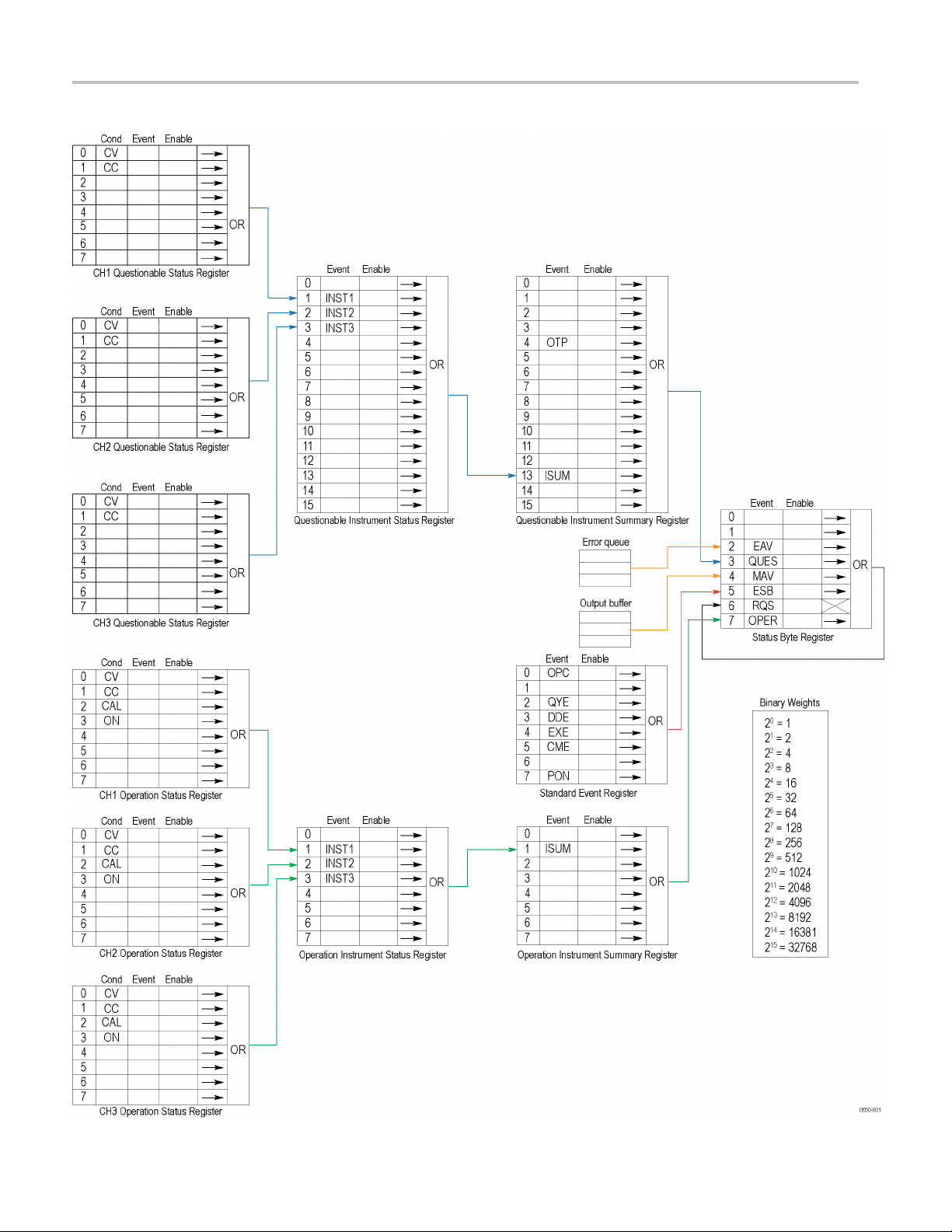
Status and Events
Figure 3-1: Error and event handling process
3-2 Series 2200 Programmable Multichannel DC Power Supplies Programmer Manual
Page 69
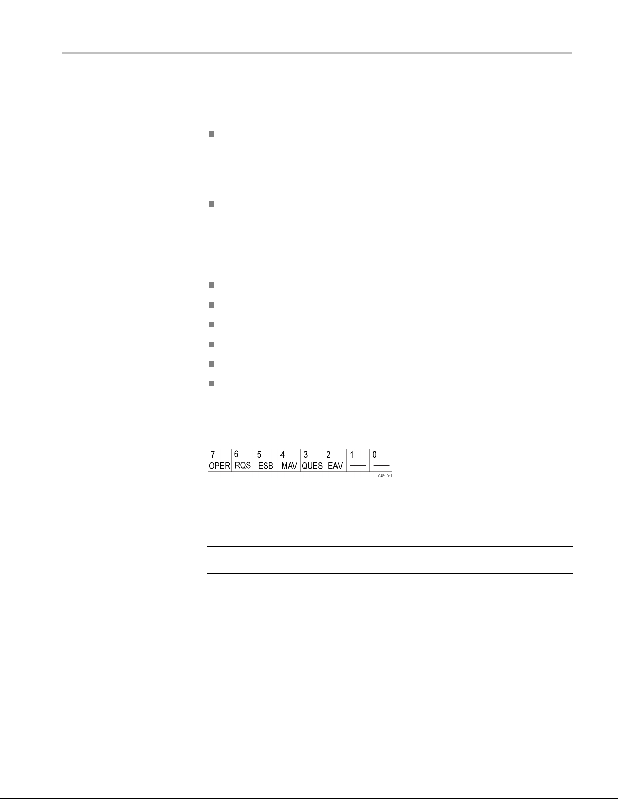
Registers
Status and Events
The registers in the event reporting system fall into two functional groups:
Status registers contain information about the status of the power supply.
They include the Status Byte Register (SBR), Standard Event Register (SER),
the Questionable Status Register (QSR), the Questionable Instrument Status
Register (QISR), the Operation Status Register (OSR), and the Operation
Instrument Status Register (OISR).
Summary registers record high-level summary information reported in the
other register groups. They include the Questionable Instrument Summary
Register (QISUR) and the Operation Instrument Summary Register (OISUR).
Status Registers
There are six types of status registers:
Status Byte Register (SBR). (See page 3-3.)
Standard Event Register (SER). (See page 3-4.)
Operation Instrument Status Register (OISR). (See page 3-4.)
Operation Status Register (OSR). (See page 3-5.)
Questionable Instrument Status Register (QISR). (See page 3-5.)
Questionable Status Register (QSR). (See page 3-6.)
The Status Byte Register (SBR). The SBR is made up of 8 bits. Bits 2, 4 and 5 are
defined in accordance with IEEE Std 488.2-1992. These bits are used to monitor
the error queue, output queue, and SER, respec
tively.
Figure 3-2: SBR bit functions
Table 3-1: SBR bit functions
Bit Function
7
6
5
4MAV
3
OPER
RQS
ESB
QUES
Operation Status Bit. Indicates that an operation
event has occurred.
Request Service. Obtained from a serial poll. Shows
that the power supply requests service from the GPIB
controller.
Event Status Bit. Shows that status is enabled and
present in the SESR.
Message Available. Shows that output is available
in the Output Queue.
Questionable Status Bit. Indicates that a
questionable event has occurred.
Series 2200 Programmable Multichannel DC Power Supplies Programmer Manual 3-3
Page 70

Status and Events
Table 3-1: SBR bit functions (cont.)
Bit Function
2EAV
1
0
————
————
Shows that information is available in the Error Queue.
Not used.
Not used.
Each bit in
an Enable Register corresponds to a bit in an Event Register. In order
for an event to be reported to a bit in the Status Byte Register, the corresponding
bit in the Enable Register must be set to one. If the bit in the Enable Register is set
to zero, the event will not affect the status bit.
Various commands set the bits in the Enable Registers. Following are descriptions
of the Enable Registers and the commands used to set them.
The Standard Event Register (SER). The SER records six types of events that can
occur w
ithin the power supply as shown in the following figure.
Figure 3-3: The Standard Event Register (SER)
le 3-2: SER bit functions
Tab
Bit Fun
7
6
5
4E
3DDE
2
1
0
ction
PON
——
——
E
CM
XE
QYE
————
OPC
er On.
Pow
on.
is bit is not used.
Th
mmand Error.
Co
the power supply was parsing a command or query.
Execution Error. Shows that an error occurred w hile
the power supply was executing a command or query.
Device Error. Shows that a device dependent error
occurred.
Query Error. E ither an attempt w as made to read the
Output Queue when no data was present or pending, or that
data in the Output Queue was lost.
This bit is not used.
Operation Complete. Shows that the operation
is complete. This bit is set when all pending operations
complete following an *OPC command.
Shows that the power supply was powered
Shows that an error occurred while
The Operation Instrument Status Register (OISR). The O peration Instrument Status
Register is made up of eight bits that note the occurrence of events as shown here.
3-4 Series 2200 Programmable Multichannel DC Power Supplies Programmer Manual
Page 71
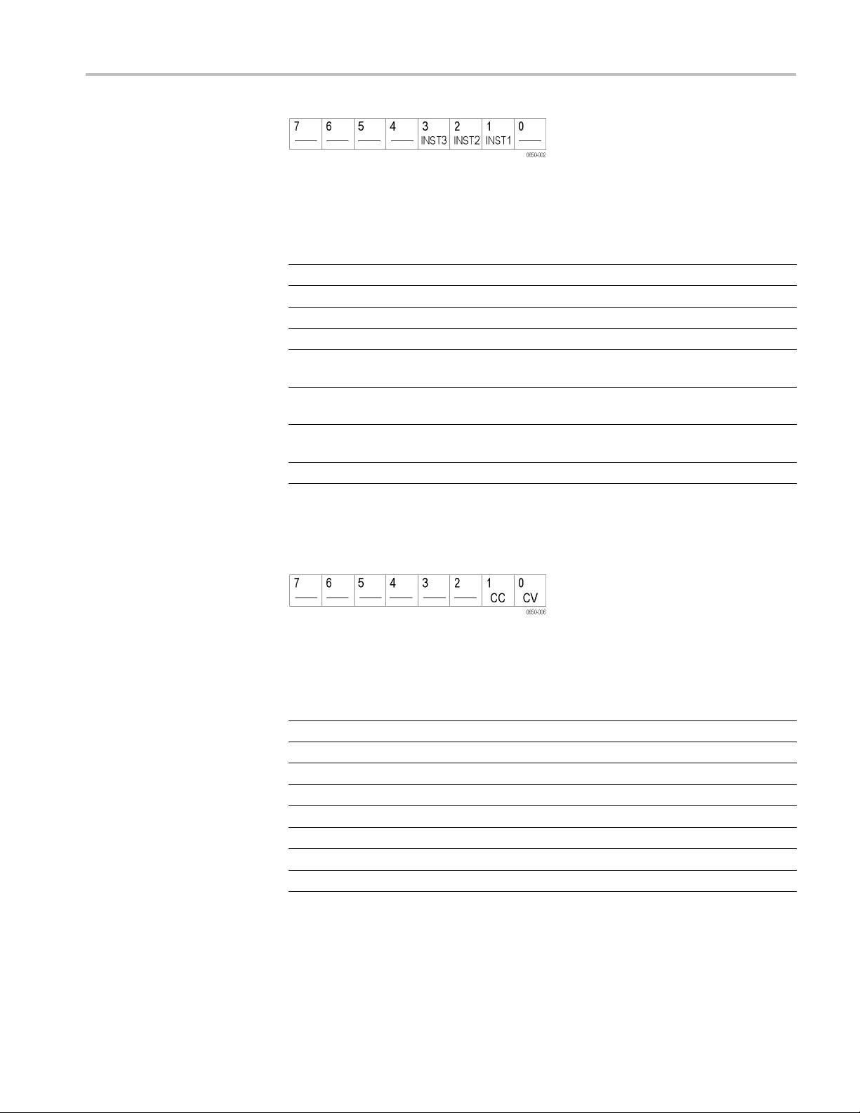
Figure 3-4: OISR bit functions
Status and Events
Tabl e 3-3: O
Bit Function
7
6
5
4
3
2
1
0
The Ope
ISR bit functions
————
————
————
————
INST3
INST2
INST1
————
This bit is not used.
This bit is not used.
This bit is
This bit is not used.
STATus:OPERation:INSTrument:ISUMmary3 is
reported to INST3.
STATus:OPERation:INSTrument:ISUMmary2 is
reported to INST2.
STATus:OPERation:INSTrument:ISUMmary1 is
reported to INST1.
This bit is not used.
not used.
ration Status Register (OSR). The Operation Status Register is made up of
8 bits which note the occurrence of four types of events as shown here.
Figure 3-5: OSR bit functions
Table 3-4: OSR bit functions
Bit Function
7
6
5
4
3
2
1
0
————
————
————
————
ON Output is ON or OFF.
CAL
CC Constant current.
CV Constant voltage.
This bit is not used.
This bit is not used.
This bit is not used.
This bit is not used.
New calibration parameters are being calculated.
The Questionable Instrument Status Register (QISR). The Questionable Instrument
Status Register is made up of 16 bits which note the occurrence of three types of
events as shown here.
Series 2200 Programmable Multichannel DC Power Supplies Programmer Manual 3-5
Page 72
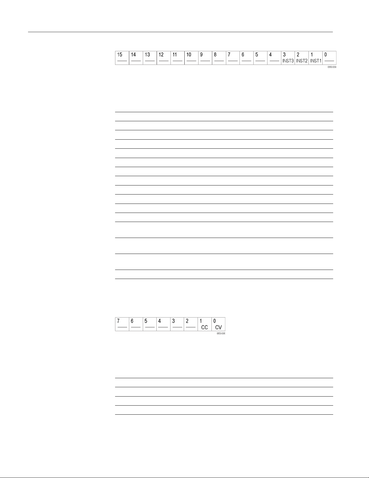
Status and Events
Figure 3-6: QISR bit functions
Table 3-5: QISR bit functions
Bit Function
15
14
13
12
11
10
9
8
7
6
5
4
3
2
1
0
————
————
————
————
————
————
————
————
————
————
————
————
INST3
INST2
INST1
————
This bit is not used.
This bit is not used.
This bit is not used.
This bit is not used.
This bit is not used.
This bit is not used.
This bit is not used.
This bit is not used.
This bit is not used.
This bit is not used.
This bit is not used.
This bit is not used.
STATus:QUEStionable:INSTrument:ISUMmary3
is reported to INST3.
STATus:QUEStionable:INSTrument:ISUMmary2
is reported to INST2.
STATus:QUEStionable:INSTrument:ISUMmary1
is reported to INST1.
This bit is not used.
The Questionable Status Register (QSR). The Questionable Status Register is
made up of 8 bits which note the occurrence of two types of events as shown in
the following figure and table.
Figure 3-7: QSR bit functions
Table 3-6: QSR bit functions
Bit Function
8
7
6
5
————
————
————
————
This bit is not used.
This bit is not used.
This bit is not used.
This bit is not used.
3-6 Series 2200 Programmable Multichannel DC Power Supplies Programmer Manual
Page 73

Table 3-6: QSR bit functions (cont.)
Bit Function
4
3
2
1
0
————
————
————
CC Constant current.
CV Constant voltage.
This bit is not used.
This bit is not used.
This bit is not used.
Status and Events
Summary R
egisters
There are two types of summary registers:
Operation Instrument Summary Register (OISUR). (See page 3-8.)
Questionable Instrument Summary Register (QISUR). (See page 3-8.)
The QIS
UR and OISUR allow you to select which events are reported to the
Status Byte Register (SBR).
Series 2200 Programmable Multichannel DC Power Supplies Programmer Manual 3-7
Page 74

Status and Events
The Operation I
nstrument Summary Register (OISUR). The Operation Instrument
Summary Register is made up of 8 bits, which note the occurrence of the condition
shown here.
Table 3-7: OISUR bit functions
Bit Function
7
6
5
4
3
2
1
0
————
————
————
————
————
————
ISUM Summary of
————
This bit is not used.
This bit is not used.
This bit is not used.
This bit is not used.
This bit is not used.
This bit is not used.
This bit is not used.
STAT:OPER:INST.
The Questionable Instrument Summary Register (QISUR). The Questionable
Instrument Summary Register is made up of 16 bits, which note the occurrence of
two types of conditions as shown here.
Figure 3-8: QISUR bit functions
Table 3-8: QISUR bit functions
Bit Function
15
14
13
12
11
10
9
8
7
6
5
4
3
————
————
ISUM Summary of
————
————
————
————
————
————
————
————
OTP Over temperature protection.
————
This bit is not used.
This bit is not used.
This bit is not used.
This bit is not used.
This bit is not used.
This bit is not used.
This bit is not used.
This bit is not used.
This bit is not used.
This bit is not used.
This bit is not used.
STAT:QUES:INST:ISUM.
3-8 Series 2200 Programmable Multichannel DC Power Supplies Programmer Manual
Page 75

Table 3-8: QISUR bit functions (cont.)
Bit Function
2
1
0
————
————
————
This bit is not used.
This bit is not used.
This bit is not used.
Status and Events
Queues
Err
*PSC Comma
nd
Output Queue
or/Event Queue
The *PSC command controls the Enable Register contents at power-on. Sending
*PSC 1 sets the Enable Registers at power on as follows:
ESER 0 (equivalent to an *ESE 0 command)
SRER 0 (equivalent to an *SRE 0 command)
Sending *PSC 0 lets the Enable Registers maintain their values in nonvolatile
memory through a power cycle.
The power supply stores query responses in the Output Queue and empties this
queue each time it receives a new command or query message after an <EOM>.
The controller must read a query response before it sends the next command (or
query) or it will lose responses to earlier queries.
The Event Queue stores detailed information on up to 32 events. When 32 events
stack up in the Event Queue, the 32nd event is replaced by event code 350,
"Queue Overflow."
Read the Event Queue with the EVENT? query (which returns only the event
number), with the EVMSG? query (which returns the event number and a text
escription of the event), or with the ALLEV? query (which returns all the event
d
numbers with a description of the event). Reading an event removes it from the
queue.
Before reading an event from the Event Queue, you must use the *ESR? query to
read the summary of the event from the SESR. This makes the events summarized
by the *ESR? read available to the EVENT? and EVMSG? queries, and empties
the SESR.
Reading the SESR erases any events that were summarized by previous *ESR?
reads but not read from the Event Queue. Events that follow an *ESR? read are
put in the Event Queue but are not available until *ESR? is used again.
Series 2200 Programmable Multichannel DC Power Supplies Programmer Manual 3-9
Page 76

Status and Events
Messages and C
Command Errors
odes
Error and event c odes with negative values are SCPI standard codes. Error and
event codes with positive values are unique to the Series 2200 Programmable
Multichanne
l DC Power Supplies.
Table 3-9: No event messages
Code Message
0 No events to report; queue empty
1
No events to report; new events pending *ESR?
The following table shows the command error messages generated by improper
syntax. Check that the command is properly formed and that it follows the rules
in the section on command Syntax.
Table 3-10: Command error messages (CME bit 5)
Code Message
101
110
114
116
117
120
130
140
150
160
165 Unmatched bracket
170
180 No entry in list to retrieve
190 Too many dimensions in entry to be returned in parameters
191 Too many char
Design error: Too many numeric suffices in Command Spec
No Input Command to parse
Numeric suffixisinvalidvalue
Invalid value in numeric or channel list, e.g. out of range
Invalid number of dimensions in a channel list
Parameter of type Numeric Value overflowed its storage
Wrong units for parameter
Wrong type of parameter(s)
Wrong number of parameters
Unmatched quotation mark in parameters (single/double)
Command keywords were not recognized
Execution Errors
The following table lists the execution errors that are detected during execution of
a command.
Table 3-11: Execution error messages (EXE bit 4)
Code Message
–200 Execution error
–221
Settings conflict
3-10 Series 2200 Programmable Multichannel DC Power Supplies Programmer Manual
Page 77

Table 3-11: Execution error messages (EXE bit 4) (cont.)
Code Message
–222
–223 Too much data
–224 Illegal parameter value
–225
–270 Macro error
–272 Macro execution error
–273 Illegal macro label
–276 Macro recursion error
–277
Data out of range
Out of memory
Macro redefinition not allowed
Status and Events
Series 2200 Programmable Multichannel DC Power Supplies Programmer Manual 3-11
Page 78

Status and Events
System Errors
Query Errors
The following t
able lists the system errors that can occur during power supply
operation.
Table 3-12: System error messages (DDE bit 3)
Code Message
–310
–350 Too many errors
System error
The following table lists the query errors that can occur during power supply
operation. These errors may indicate that there was a problem during the query
process and that your query will not be performed.
Table 3-13: Query error messages (Standard Event Status Register bit 2)
Code Message
–400
–410
–420
–430
–440
Query error
Query INTERRUPTED
Query UNTERMINATED
Query DEADLOCKED
Query UNTERMINATED
Self Test Errors
The following table lists the self test errors that can occur during power supply
operation.
Table 3-14: Self test error messages (Standard Event Status Register bit 3)
Code Message
0Noerror
1 Module Initialization Lost
2
3
4
5
10
40
41
80
Mainframe Initialization Lost
Module C alibration Lost
Non-volatile RAM STATE section checksum failed
Non-volatile RAM RST section checksum failed
RAM selftest
Flash write failed
Flash erase failed
Digital I/O selftest error
3-12 Series 2200 Programmable Multichannel DC Power Supplies Programmer Manual
Page 79

Status and Events
Device Dependent Errors
The following t
able lists the device errors that can occur during power supply
operation. These errors may indicate that the power supply needs repair.
Table 3-15: Device dependent error messages (DDE bit 3)
Code Message
220 Front panel uart overrun
221
222 Front panel
223
224 Front panel timeout
225
226
401
402
403
404
405
406
407
603
604 Measurement overrange
Front panel uart framing
uart parity
Front pane
Front Crc Check error
Front Cmd Error
CAL switch prevents calibration
CAL password is incorrect
CAL not enabled
Computed readback cal constants are incorrect
Computed programming cal constants are incorrect
Incorrect sequence of calibration commands
CV or CC status is incorrect for this command
FETCH of data that was not acquired
l buffer overrun
Series 2200 Programmable Multichannel DC Power Supplies Programmer Manual 3-13
Page 80

Status and Events
3-14 Series 2200 Programmable Multichannel DC Power Supplies Programmer Manual
Page 81

Appendices
Page 82

Page 83
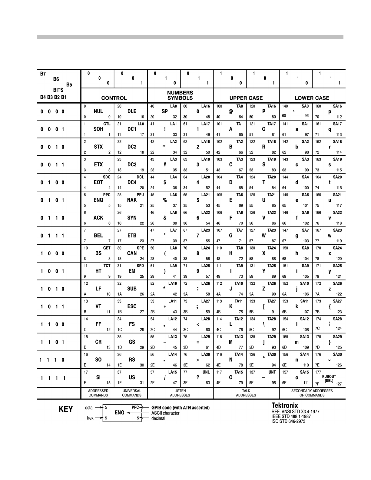
Appendix A: ASCII Code Chart
Series 2200 Programmable Multichannel DC Power Supplies Programmer Manual A-1
Page 84

Appendix A: ASCII Code Chart
A-2 Series 2200 Programmable Multichannel DC Power Supplies Programmer Manual
Page 85

Appendix B: Programming Examples
Example 1
This example i
It demonstrates basic communication with the power supply and error checking.
The program establishes communication with the power supply and puts it into
remote mode. It then initializes the voltage and current and turns the output on.
It sends new values for the voltage and current, and reads back the actual meter
values before turning off the power supply output and closing communications.
s written in the C programming language; NIVISA can be used.
Series 2200 Programmable Multichannel DC Power Supplies Programmer Manual B-1
Page 86

#include "stdafx.h"
#include <visa.h>
#include <stdio.h>
#include <string.h>
#include <time.h>
#include <conio.h>
#include <stdlib.h>
ViSession defaultRM; // Resource manager ID
ViSession KI200; // Identifies the power supply
long ErrorStatus;
char commandString[256];
char ReadBuffer[256];
void OpenPort();
void SendSCPI(char* pString);
void CheckError(char* pMessage);
void delay(clock_t wait);
void ClosePort();
int main(int argc, _TCHAR* argv[])
{
char Buffer[256];
float setting[3][2]={
{11.9, 0.55},
{15.15, 0.25},
{2.5, 0.15}
} ; // Voltage, current for three channels
float query[3][2];
unsigned int i;
OpenPort();
// Query the power supply ID, read the response and print it
sprintf(Buffer, "*IDN?");
SendSCPI(Buffer);
printf("Instrument identification string:%s \n", Buffer);
SendSCPI("*RST"); // Reset the power supply
SendSCPI("OUTPut 1"); // Turn the output on
for (i=0; i<3; i++)
{
printf("setting Channel: %d, voltage(V):%f, current(A):%f \n", i+1,
setting[i][0], setting[i][1]);
ErrorStatus = viPrintf(KI200, "INSTrument:NSELect %d\n", i+1); // Select the channel
CheckError("Unable to select the channel");
ErrorStatus = viPrintf(KI200,"VOLTage %f\n",setting[i][0]); // Set the output voltage
CheckError("Unable to set voltage");
ErrorStatus = viPrintf(KI200, "CURRent %f\n",setting[i][1]); // Set the output current
CheckError("Unable to set current");
}
SendSCPI("*SAV 4");
delay (10);
for (i=0; i<3; i++)
B-2
Series 2200 Programmable Multichannel DC Power Supplies Programmer Manual
Page 87

{
ErrorStatus = viPrintf(KI200, "INSTrument:NSELect %d\n", i+1); //Select the channel
CheckError("Unable to select the channel");
ErrorStatus = viPrintf(KI200,"Measure:voltage?\n"); // Measure the output voltage
CheckError("Unable to write the device");
ErrorStatus = viScanf(KI200,"%f",&query[i][0]); // Retrieve the reading
CheckError("Unable to read voltage");
ErrorStatus = viPrintf(KI200,"Measure:current?\n"); // Measure the output current
CheckError("Unable to write the device");
ErrorStatus = viScanf(KI200,"%f",&query[i][1]); // Retrieve the reading
CheckError("Unable to read current");
printf("Channel: %d, measured voltage(V):%f, current(A):%f \n", i+1,
query[i][0], query[i][1]);
}
return 0;
}
void OpenPort()
{
//Open communication session with the power supply
ErrorStatus = viOpenDefaultRM(&defaultRM);
ErrorStatus =viOpen(defaultRM,
"USB0::0X0699::0X0397::083001106673201002::INSTR",0,0,&KI200);
/*When using the GPIB interface, replace the above command line with
"GPIB0::21::INSTR". Note the argument "21" is an example and refers to the GPIB address.
Substitute the appropriate GPIB address in the command line.*/
CheckError("Unable to open the port");
SendSCPI("SYSTem:REMote");
}
void SendSCPI(char* pString)
{
char* pdest;
strcpy(commandString,pString);
strcat(commandString, "\n");
ErrorStatus = viPrintf(KI200, commandString);
CheckError("Can't Write to Power Supply");
pdest = strchr(commandString, '?'); // Search for the query command
if (pdest != NULL)
{
ErrorStatus = viBufRead(KI200, (ViBuf)ReadBuffer,
sizeof(ReadBuffer), VI_NULL);
CheckError("Can't read from driver");
strcpy(pString, ReadBuffer);
}
}
void ClosePort()
{
Series 2200 Programmable Multichannel DC Power Supplies Programmer Manual B-3
Page 88

viClose(KI200);
viClose(defaultRM);
}
void CheckError(char* pMessage)
{
if(ErrorStatus != VI_SUCCESS)
{
printf("\n %s",pMessage);
ClosePort();
exit(0);
}
}
void delay(clock_t wait)
{
clock_t goal;
goal = wait + clock();
while(goal > clock());
}
B-4
Series 2200 Programmable Multichannel DC Power Supplies Programmer Manual
Page 89

Appendix B: Programming Examples
Example 2
This example is
can be used. It demonstrates establishing a connection with the power supply,
putting it into remote mode, initializing the current and voltage for channel 1 and
channel 2, and initializing the track settings function.
written in the C programming language; TekVISA or NIVISA
Series 2000 Programmable Multitichannel Power Supplies Programmer Manual B-5
Page 90

#include "stdafx.h"
#include <visa.h>
#include <stdio.h>
#include <string.h>
#include <time.h>
#include <conio.h>
#include <stdlib.h>
ViSession defaultRM; // Resource manager ID
ViSession KI200; // Identifies power supply
long ErrorStatus;
char commandString[256];
char ReadBuffer[256];
void OpenPort();
void SendSCPI(char* pString);
void CheckError(char* pMessage);
void delay(clock_t wait);
void ClosePort();
int main(int argc, _TCHAR* argv[])
{
char Buffer[256];
float setting[2][2] = {
{2.5, 0.1},
{7.5, 0.2}
}; // Initial the voltage and current for CH1 and CH2
float voltage, current;
unsigned int i;
OpenPort();
// Query the power supply ID, read the response and print it
sprintf(Buffer, "*IDN?");
SendSCPI(Buffer);
printf("Instrument identification string:%s \n", Buffer);
SendSCPI("*RST"); // Reset the power supply
SendSCPI("OUTPut 1"); // Turn output on
SendSCPI("OUTPut:TRACK 0"); // Check that the track function is turned off
for (i=0; i<2; i++)
{
printf("initial value for Channel: %d, voltage(V):%f, current(A):%f \n",
i+1, setting[i][0], setting[i][1]);
ErrorStatus = viPrintf(KI200,"APPLy CH%d, %f, %f\n",i+1,
setting[i][0], setting[i][1]); //set the output valtage
CheckError("Unable to use APPLy command to set voltage and current");
}
delay(10);
SendSCPI("OUTPut:TRACK 1"); // Enable the track function
delay(5);
// Change the voltage and current for CH1; the values for CH2 will change automatically
voltage = 5.5;
current = 0.23;
B-6 Series 2200 Programmable Multichannel DC Power Supplies Programmer Manual
Page 91

ErrorStatus = viPrintf(KI200,"APPLy CH1, %f, %f\n", voltage, current); //Set the output voltage
CheckError("Unable to use APPLy command to set voltage and current");
return 0;
}
void OpenPort()
{
// Open communication session with the power supply
ErrorStatus = viOpenDefaultRM(&defaultRM);
ErrorStatus =viOpen(defaultRM,
"USB0::0X0699::0X0397::083001106673201002::INSTR",0,0,&KI200);
/*When using the GPIB interface, replace the above command line with
"GPIB0::21::INSTR". Note the argument "21" is an example and refers to the GPIB address.
Substitute the appropriate GPIB address in the command line.*/
CheckError("Unable to open the port");
SendSCPI("SYSTem:REMote");
}
void SendSCPI(char* pString)
{
char* pdest;
strcpy(commandString,pString);
strcat(commandString, "\n");
ErrorStatus = viPrintf(KI200, commandString);
CheckError("Can't Write to Power Supply");
pdest = strchr(commandString, '?'); // Search for query command
if (pdest != NULL)
{
ErrorStatus = viBufRead(KI200, (ViBuf)ReadBuffer,
sizeof(ReadBuffer), VI_NULL);
CheckError("Can't read from driver");
strcpy(pString, ReadBuffer);
}
}
void ClosePort()
{
viClose(KI200);
viClose(defaultRM);
}
void CheckError(char* pMessage)
{
if(ErrorStatus != VI_SUCCESS)
{
printf("\n %s",pMessage);
ClosePort();
exit(0);
}
}
Series 2200 Programmable Multichannel DC Power Supplies Programmer Manual B-7
Page 92

void delay(clock_t wait)
{
clock_t goal;
goal = wait + clock();
while(goal > clock());
}
B-8 Series 2200 Programmable Multichannel DC Power Supplies Programmer Manual
Page 93

Appendix B: Programming Examples
Example 3
This example is
can be used. The program demonstrates setting trigger settings.
written in the C programming language; TekVISA or NIVISA
Series 2200 Programmable Multichannel DC Power Supplies Programmer Manual B-
9
Page 94

#include "stdafx.h"
#include <visa.h>
#include <stdio.h>
#include <string.h>
#include <time.h>
#include <conio.h>
#include <stdlib.h>
ViSession defaultRM; // Resource manager ID
ViSession KI200; // Identifies the power supply
long ErrorStatus;
char commandString[256];
char ReadBuffer[256];
void OpenPort();
void SendSCPI(char* pString);
void CheckError(char* pMessage);
void delay(clock_t wait);
void ClosePort();
int main(int argc, _TCHAR* argv[])
{
char Buffer[256];
float trig_setting[3][2]={
{11.9, 0.55},
{16.15, 0.25},
{2.5, 0.15}
}; // Voltage, current for trigger
unsigned int i;
OpenPort();
// Query the power supply ID, read the response and print it
sprintf(Buffer, "*IDN?");
SendSCPI(Buffer);
printf("Instrument identification string:%s \n", Buffer);
SendSCPI("*RST"); // Reset the power supply
SendSCPI("OUTPut 1"); // Turn the output on
for (i=0; i<3; i++)
{
printf("setting Channel: %d, voltage(V):%f, current(A):%f \n", i+1,
trig_setting[i][0], trig_setting[i][1]);
ErrorStatus = viPrintf(KI200, "INSTrument:NSELect %d\n", i+1); // Select the channel
CheckError("Unable to select the channel");
// Set the output valtage
ErrorStatus = viPrintf(KI200,"VOLTage:TRIGgered %f\n",trig_setting[i][0]);
CheckError("Unable to set voltage");
// Set the output current
ErrorStatus = viPrintf(KI200, "CURRent:TRIGgered %f\n",trig_setting[i][1]);
CheckError("Unable to set current");
}
// Select the channels that will respond the trigger command
SendSCPI("INSTrument:COUPle ALL");
B-10 Series 2200 Programmable Multichannel DC Power Supplies Programmer Manual
Page 95

SendSCPI("*TRG");
return 0;
}
void OpenPort()
{
// Open communication session with the power supply
ErrorStatus = viOpenDefaultRM(&defaultRM);
ErrorStatus =viOpen(defaultRM,
"USB0::0X0699::0X0397::083001106673201002::INSTR",0,0,&KI200);
/*When using the GPIB interface, replace the above command line with
"GPIB0::21::INSTR". Note the argument "21" is an example and refers to the GPIB address.
Substitute the appropriate GPIB address in the command line.*/
CheckError("Unable to open the port");
SendSCPI("SYSTem:REMote");
}
void SendSCPI(char* pString)
{
char* pdest;
strcpy(commandString,pString);
strcat(commandString, "\n");
ErrorStatus = viPrintf(KI200, commandString);
CheckError("Can't Write to Power Supply");
pdest = strchr(commandString, '?'); // Search for the query command
if (pdest != NULL)
{
ErrorStatus = viBufRead(KI200, (ViBuf)ReadBuffer, sizeof(ReadBuffer),
VI_NULL);
CheckError("Can't read from driver");
strcpy(pString, ReadBuffer);
}
}
void ClosePort()
{
viClose(KI200);
viClose(defaultRM);
}
void CheckError(char* pMessage)
{
if(ErrorStatus != VI_SUCCESS)
{
printf("\n %s",pMessage);
ClosePort();
exit(0);
}
}
void delay(clock_t wait)
Series 2200 Programmable Multichannel DC Power Supplies Programmer Manual B-11
Page 96

{
clock_t goal;
goal = wait + clock();
while(goal > clock());
}
B-12 Series 2200 Programmable Multichannel DC Power Supplies Programmer Manual
Page 97

Appendix B: Programming Examples
Example 4
This example sh
ows a command sequence that configures series mode, output
voltage, and current.
Talker Listen
configure the output voltage and current.
SYSTem:REM
*IDN?
*RST
INSTrument:COMBine:SERies
OUTPut 1
VOLTage 35
CURRent
OUTPut:SERies?
*OPC
MEASure:VOLTage?
MEASure:CURRent?
0.3
er Script1: co nfigure to the series mode and
ote
Example 5
example shows a command sequence that uses the APPLy command to
This
configure voltage and current values.
ker Listener Script2: use the APPLy command to configure
Tal
the voltage and current value.
Tem:REMote
SYS
*IDN?
*RST
OUTPut 1
APPLy CH1,15.0,1
APPLy CH2,10.0,0.5
APPLy CH3,5.0,0.1
*OPC
MEASure:VOLTage? ALL
MEASure:CURRent? ALL
Series 2000 Programmable Multichannel Power Supplies Programmer Manual B-13
Page 98

Appendix B: Programming Examples
Example 6
This example sh
ows a command sequence to couple all outputs with voltage
and current triggered levels.
Talker Listen
to couple all output with voltage and current triggered
levels.
SYSTem:REMote
*IDN?
*RST
OUTPut 1
INSTrument:NSELect 1
VOLTage:TRIGgered 6
CURRent:TRIGgered 0.2
INSTru
VOLTage:TRIGgered 10
CURRent:TRIGgered 0.5
INSTrument:NSELect 3
ment:NSELect 2
er Script1: us e the INSTrument:COUPle command
VOLTage:TRIGgered 1
CURRent:TRIGgered 0.1
Trument:COUPle CH1, CH2, CH3
INS
*TRG
B-14 Series 2000 Programmalable Multichannel lDC Power Supplies P rogrammer
Page 99

Appendix C: Default Setup
The following table lists the settings that are restored when you return the power
supply to default settings.
Tabl e C-1: D
Menu or system Default setting
VOLT:LIM
VOLT:LIM:STAT OFF
OUTP OFF
VOLT
CURR
OUTP:TIM:DEL
OUTP:TIM OFF
efault settings
MAX
1V
0.1 A
60
Series 2200 Programmable Multichannel DC Power Supplies Programmer Manual C-1
Page 100

Appendix C: Default Setup
C-2 Series 2200 Programmable Multichannel DC Power Supplies Programmer Manual
 Loading...