

Page 1
SerialXpress®– Advanced Jitter Generation for AWG
SDX100, SDXUP Data Sheet
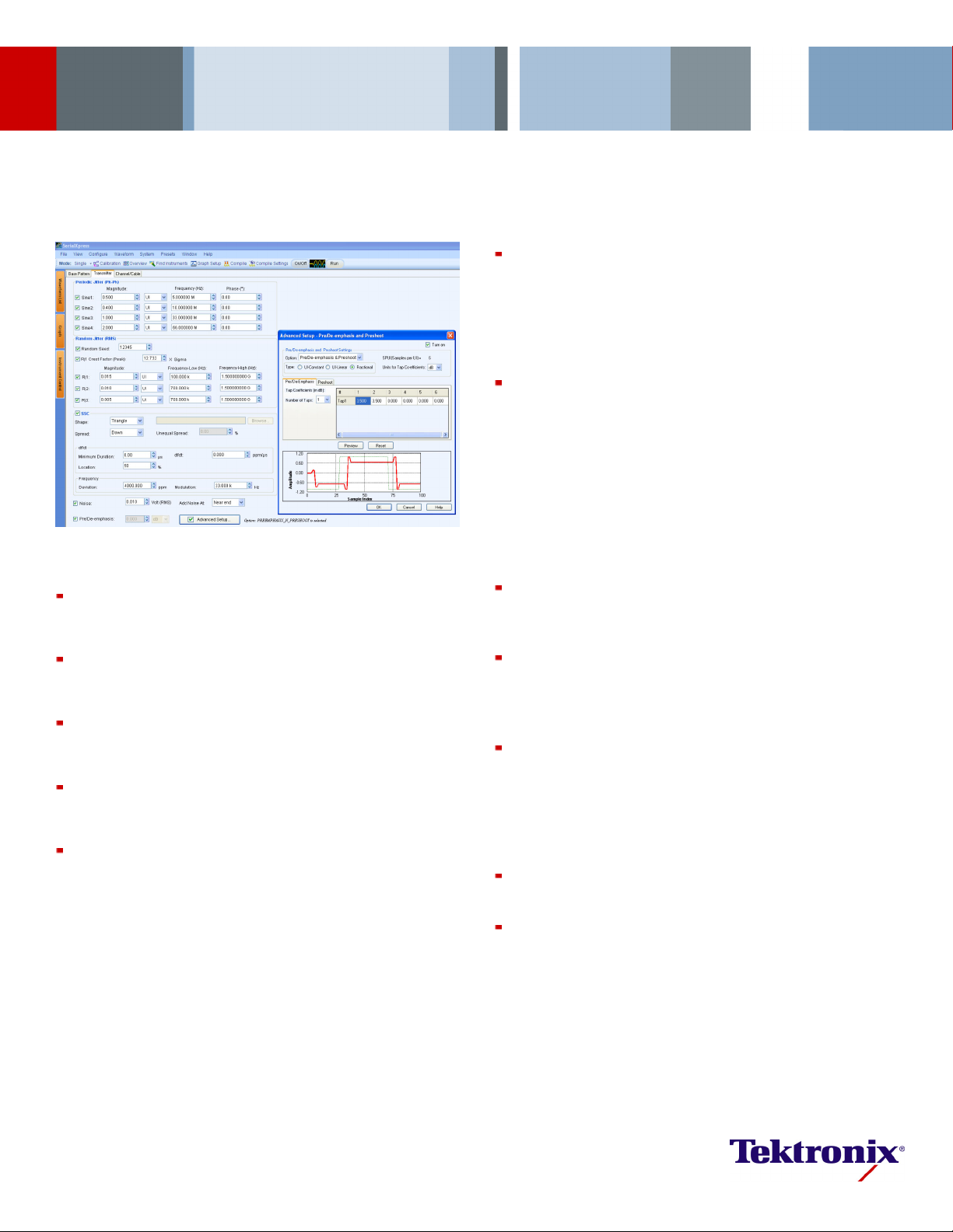
Programmable pre/de-emphasis and preshoot: Most of the
next-generation standards like PCIe, 10GbE, SAS, or USB 3.0 need
more than one tap for pre/de-emphasis signal generation. The
s Advanced Pre/De-emphasis feature offers the ultimate in
mpliance testing of high-speed
Features & Benefits
Flexibility: Jitter generation has become so flexible that the user now
has the freedom to try various permutations and combinations of jitter
ers like Pj, Rj, ISI, Noise, Delay, etc.
paramet
Replicate scenarios: The signals are digitally synthesized. All AWG
setups can be recalled and the scenarios can be replicated on any ot her
AWG within seconds.
Analog nature of digital signals: In reality all digital signals are analog
in nature and hence SerialXpress exploits the capabilities of an AWG to
generate real-world signals.
Ease of use: It is ea sy to integrate a multitude of Sj tones into the
waveforms at no additional cost. Band-limited Rj can be injected with
ease.
actor Emulation (CFE): Users can now apply any amount of
Crest F
peak pseudo-random jitter needed to their bit patterns which can reduce
test times. Test cases can be repeated accurately enabling fast receiver
debug cycles. SerialXpress can also create worst-case scenarios to
stress receivers by accurately contro lling the Crest Factor of the random
jitter.
SerialXpres
flexibility, giving users the ability to progra m the pre/de-emp hasis and
preshoot sample by sample.
Channel emulation through cascaded S-parameter filter: Touchstone
files can easily be inserted to simulate the e x act behavior of cable
emulators, which can be again controlled and modified by adding jitter
and other parameters. You can also tweak the imported touchstone
file data to adjust the ISI and see how the receiver responds to those
variations. The effect of the channel can also be de-embedded by
selecting the Inverse filtering option. Closed EYE can be opened up by
adding the right amount of pre-emphasis or by varying the rise time. You
can also cascade up to 6 touchstone files to emulate a cascaded channel
that might include connectors, fixtures, and channel models.
ISI Direct Dial-in: ISI can be directly dialed-in at ease. It’s no longer
necessary to use FR4 traces which are inflexible and need frequent
calibration when switching from one to another.
Presets: SerialXpress supports any emerging standard data rate from
500 Kb/s to 8 Gb/s when teamed with the appropriate Tektronix AWG.
There are ready-to-use presets that allow you a head-start on your
testing.
Offline mode: SerialXpress applications can run on an external PC,
thereby reducing the time taken to synthesize large waveforms and
leaving the AWG free for continued testing.
Applications
Design, debug, characterization, and co
serial data receivers
SATA, PCIe, SAS, DisplayPort, Fibre Channel, HDMI, USB, MIPI,
Receiver Testing
Page 2

Data Sheet
Jitter Generation Made Easy
SerialXpress is a powerful easy-t o-use software p ackage to synthesize
high-speed serial data signals for Arbitrary Waveform Generators (AWG).
It runs as an integral part of the AWG5000/7000 Series arbitrary waveform
generators or from an external PC.
SerialXpress enables creation of exact waveforms required for
thorough and repeatable design validation, margin/characterization, and
conformance testing of high-speed serial data receivers. It considerably
simplifies the signal creation and jitter simulations, thus reducing overall
development and test time.
SerialXpress, in addition to supporting g eneration of jitter (Random, Periodic
(Sinusoidal), Inter Symbol Interference (ISI), and Duty Cycle Distortion
(DCD)), also supports Spread Spectrum Clocking (SSC), pre-emphasis,
and noise addition. This allows the user to create a combination of various
impairments simultaneously to stress the receiver. Se rialXpress also allows
the waveforms to be captured from Tektronix oscilloscopes and to be
replayed using arbitrary waveform generators.
A programmatic interface enables easy integration of SerialXpress into test
automation systems.
Scrambling, PWM, 4-PAM, and 8b/10b Encoding
The input data pattern can be scrambled by defining a polynomial. The user
could enable the 8b/10b encoding option if the input pattern is in 8-bit word
format before applying other im pairment s like jitter, SSC, and ISI. Users can
also define the pattern duty cycle using the P ulse Width Modulation (PWM)
feature, which allows for alternatively e ncoding the bit stream to 4-PAM.
Jitter Addition
Up to 4 different sinusoidal jitters with different amplitudes, frequencies, and
phases can be adde d to the base pattern. Three independent band-limited
random jitters can also be added to the base pattern.
SSC Modulation
SSC can be a
modulation, and df/dt. It supports Triangular, Sinusoidal, and Custom SSC
profiles, where the custom SSC profile allows you to import your own
user-defined profile by literally allowing any kind of shape to be added
as SSC to the base pattern. You can also define the exact location and
duration of df/dt on the SSC slope.
dded with precisely controlled profile, spread, deviation,
Advanced Pre/De-emphasis and Noise
Many standards such as PCIe require the output waveform to b e
pre/de-emphasized. SerialXpress allows easy add ition of pre/de-emphasis,
including preshoot, with all other jitter parameters. Vertical noise can also
be added at both
near and far end of th e channel.
ISI Creation
SerialXpress allows creation of ISI in two ways. First, the ISI value can
be directly di
Tektronix sampling oscilloscope or a vector network analyzer can be directly
convolved with the base pattern to recreate the channel characteristics. By
applying inverse filtering the effects of the channel can be de-embedded
from the system. Also, ISI within the S-parameter can be scaled upwards or
downwards, which will alter the characteristics of th e channel.
aled-in. Second, an S-parameter file generated from a
Delay
SerialXpress allows users to introduce delay to the waveform, and this
feature can also generate skew between channels or patterns.
Base Pattern
SerialXpress is bundled with several sample patterns for various standards
like SATA, Display Port, SAS, PCIe, HDMI, USB, MIPI, and Fibre Channel.
Patterns ca
loaded as a file.
Idle State*
Standards
followed by a b urst. Now the user can directly create this idle state without
the need of using additional power dividers. Noise and offset can also be
added to these idle state waveforms. Idle state can also be defined as a part
of pattern definition.
n also be directly entered in a Binary, Symbol, or Hex editor or
1
like SATA call for OOB signaling which requires idle state
Calibration
SerialXpress has a built-in calibra tion routine which controls a Tektronix
oscilloscope and calibrates the output of the AWG for periodic jitter and
random jitter, reducing the need for time-consuming manual calibration.
Bandwidth Expansion Filter
Rise time of the AWG can be expanded further by applying the bandwidth
expansion filter. For example, when used with AWG7122C and Option 06,
this comp
the bandwidth up to 9 GHz.
*1When idle state (z) is included in the pattern definition, no jitter is applied.
ensates for the DAC roll-off at higher frequencies and extends
2 www.tektronix.com/signal_generators
Page 3
Marker Outputs
Marker outputs can be configured to be the same as the input base pattern
or to generate clocks at a user-defined frequency including subdata rates.
Batch Processing
When more than one patte rn needs to be synthesized, you can use
batch processing that enables creation of multiple waveforms with a
combination of random jitter and sinusoidal jitter with a maximum of 4
different fre
quencies.
SDX100, SDXUP
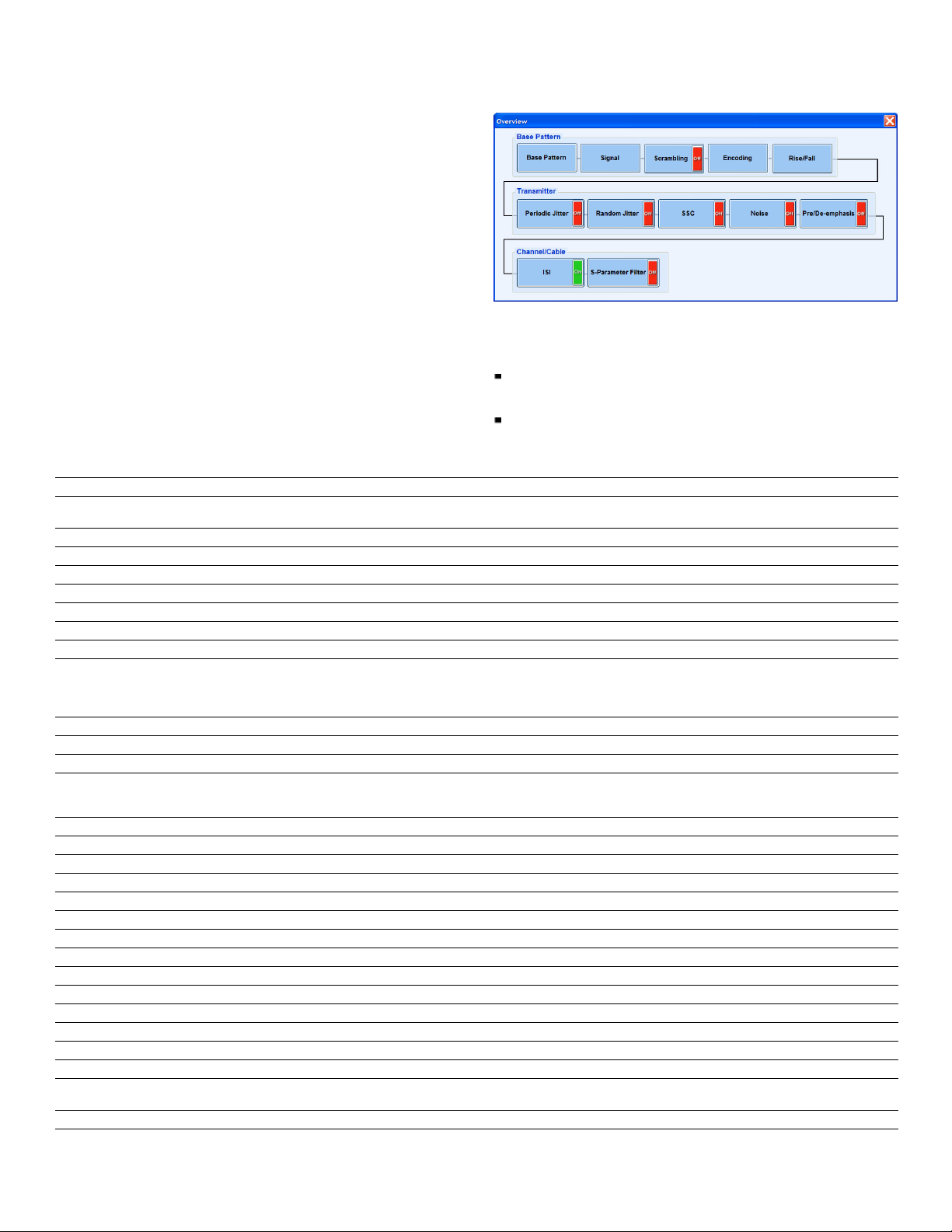
Overview Win
dow
Overview window
All the jitter parameters can be switched ON/OFF from th e Overview
window.
Characteristics
User Interface – Can reside and run on either Windows XP Professional or Windows
Vista.
Compatibility for Import of Waveform/Pattern Files
Tektronix TDS6000, DSA/DPO70000, MSO70000, and DSA/DPO700 0
Series oscilloscopes.
Tekt r o ni x D
ata Timing Generators DTG500 0 Series
Instrument Control
Characteristic
Tektronix A rbitrary Waveform Generators
Controls SerialXpress®runs on an external PC or an integral part of the AWG5000/7000 Series. Waveform transfer and control of the
Analog
Digital markers Amplitude High, Low, and Delay
Tektronix Oscilloscopes
Controls Remote control Tektronix oscilloscope parameters from SerialXpress
General settings Run, Stop, Single, and Autoset
Vertical settings
Horizontal settings
Description
AWG5000/7000 Series can be performed directly from SerialXpress
Interleave and Zeroing ON/OFF, DAC Resolution, Sampling Frequency, Amplitude, Offset, Run, Stop, and Channel Output ON/OFF
Channel, Scale
Scale, Record Length, Sampling Rate
SerialXpress for Jitter Creation
ption
Characteristic
Mode
ata
Base D
Standard patterns
SATA Idle state, LFTP, MFTP, HFTP, SFCPAlignR12, SFCPAlignR12-badbit, Gen1R12FCP4A, Gen1R25FCP4A, Gen1R10FCP2AnewLBP,
PCIe Compliance Pattern
SA S CJ TPAT, J TPAT RD +, JTPAT R D–
Display port
HDMI
Fibre channel
USB minadd1N,minadd1P,TSEQ,CPO,CP1,CP2,CP3,CP4,CP6,CP8,BERC,BRST
MIPI
General Clock, PRBS (7, 9, 15, 16, user defined)
File Input
Pattern Editor
Data Rate
Encoding
Pulse Width Modulation
T_Minor 0 to 0.5 UI
Rise Time
DCD
Descri
Single, Sequence
Gen1R10FCP2AnewLBPErr, Gen2R8FCP2AnewLBP, Gen2R8FCP2AnewLBPErr, LTDP RD–, LTDP RD+, HTDP RD–, HTDP RD+,
LFSCP RD–, LFSCP RD+, SSOP RD–, SSOP RD+, LBP, COMP RD–, COMP RD+
PRBS7, D24.3, D10.2, Frequency Lock, and Symbol Lock
480P Gray RGB, 720P Gray RGB, 1080P 8-bit Gray RGB, 1080P 10-bit Gray RGB, 1080P 12-bit Gray RGB
JT PAT, CJ TPAT, S PAT, CS PAT
CJTPAT_FC, Clock
Annotated .txt – Binary (1, 0, z) and Symbol (D, K, z words)*
Binary, Hex, Symbol
500 Kb/s to 8 Gb/s (direct synthesis with ×3 oversampling) and 12 Gb/s (binary data with ×2 oversampling)
3
NRZ, NRZI, 4-PAM*
ON/OFF
10/90, 20/80
1/samplingrateto1/datarate
0to1UI
, 8B/10B with starting disparity RD+, RD–
2
www.tektronix.com/signal_generators 3
Page 4

Data Sheet
Characteristic
Periodic Jitter
Description
Up to a maximum of 4 sinusoidal jitter
Amplitude 0 to 50 UI
Frequency
10kHztodatarate/2
Phase 0 to 360 degrees
Random Jitter
Up to max of 3 (Rj1, Rj2, and Rj3) with Random seed ON/OFF
Amplitude 0 to 0.5 UI
Frequency
Crest Factor
1Hztodatarate/2
1to20
Idle State 53 nS to 100 μS
Offset
–0.5 V to +0.5 V
SSC
Shape Triangle, Sinusoidal, Custom
Spread Up, Down, Center, Unequal (0 to 100%)
df/dt
df/dt 0 to 5000 ppm/μs
Minimum duration 0 to 5 μs
Location
20% to 80%
Frequency deviation 0 to 200,000 ppm
Frequency modulation 0 to 500 kHz
Noise 0 to 100 ppm
Vertical Noise
Pre/De-emphasis
0to0.5V
0to20dB
with far end or near end
RMS
Advanced Pre/De-emphasis ON/OFF
Options Pre/De-emphasis, Preshoot, Pre/De-emphasis & Preshoot
Type
Units for tap co-efficients
UI-Constant, UI-Linear, Fractional
dB, Volts
Delay 0 to 50 ps
ISI Direct Dial-in
0to1UI
S-parameter
Mode
Filter bandwidth
Noncascading, Cascading (6 max)
None, Auto, and Custom
Plot frequency response ON/OFF
File formats s1p, s2p, s4p, and s8p (single-ended and differential)
ISI scaling
0to10
Inverse filter (de-embed) ON/OFF
Aggressor
Enabled when s8p touchstone file is selected
Signal Pattern from file,Clock,SameasVictim
Amplitude scale 0 to 5
Data rate
Direction
500 Kb/s to 12 Gb/s
Same as Victim, Opposite to Victim
Swap Aggressor and Victim ON/OFF
Presets
SATA Gen1, Gen2, Gen3
USB 3.0
DisplayPortHBR,RBR
HDMI 27 MHz, 222 MHz, 74.25 MHz, and 148.5 MHz at 60 Hz
Batch Processing
Random jitter 0 to 0.5 UI with 0.01 increments
Sinusoidal jitter
0to50UIwith0.01increments
Sinusoidal frequency 10 kHz to data rate/2 (max of 4 frequencies)
Bandwidth Enhancement Filter
Calibration
ON/OFF
Periodic Jitter, Random Jitter
4 www.tektronix.com/signal_generators
Page 5

SDX100, SDXUP
Characteristic
Description
Marker Setting
Base pattern
Clock frequency Data rate, data rate/2, data rate/4, data rate/8, user defined (in Hz)
Graphs
DPO EYE
Normal EYE
Rise/Fall Time
Simulated Data
Random, Periodic, and Total Jitter
Jitter Summary
TIE Spectrum
entstheidlestateinapatterndefinition.
*2"z" repres
3
*
4-PAM and PWM are mutually exclusive.
System Requirements
The following PC configuration is required to install the offline version:
PC with genuine Intel Pentium class >1.2 GHz processor recommended
Ordering Information
SerialXpress
Jitter Generation Software Package for Tektronix AWG5000/7000 Series.
Includes: USB dongle.
Intel or 100% compatible motherboard chipset
Windows XP or Windows Vista Operating System
1 Gigabytes (GB) RAM
Software Packages and Options
Option
SDX100 Jitter Generation Software Package for the AWG5000/7000
2 GB of available hard disk space for the applications an d documentation
XVGA 1024×768 with 120 dpi font size recommended
CD-ROM or D VD drive
Keyboard and Microsoft m ouse or compatible pointing device
Note: The hardware requirements detailed here are the minimum required.
Additional processing power and memory will increase the performance of the
generation software.
Upgrade Options
SDXUP Base software upgrade for SDX100
®
Description
Series (includes USB dongle)
Opt. ISI S-parameter and ISI creation option
(requires SDX100 as prerequisite)
Opt. SSC Spread Spectrum Clock addition option
(requires SDX100 as prerequisite)
Opt. ISI Upgrade to include S-parameter and ISI creation option for
SDX100
Opt. SSC Upgrade to include Spread Spectrum Clock option for
SDX100
Product(s) are manufactured in ISO registered facilities.
Product(s) complies with IEEE Standard 488.1-1987, RS-232-C, and with Tektronix
Standard Codes and Formats.
www.tektronix.com/signal_generators 5
Page 6

Data Sheet
6 www.tektronix.com/signal_generators
Page 7

SDX100, SDXUP
www.tektronix.com/signal_generators 7
Page 8

Data Sheet
Contact Tektronix:
ASEAN / Australa
Balkans, Israel, South Africa and other ISE Countries +41 52 675 3777
Central East Eu
Mexico, Central/South America & Caribbean (52) 56 04 50 90
* European toll-free number. If not accessible, call: +41 52 675 3777
rope, Ukraine, and the Baltics +41 52 675 3777
Central Europe & Greece +41 52 675 3777
Middle E ast,
Asia, and North Africa +41 52 675 3777
The Netherlands 00800 2255 4835*
People’s Rep
Republic of
United K ingdom & Ireland 00800 2255 4835*
sia (65) 6356 3900
Austria 00800 2255 4835*
Belgium 00800 22
Brazil +55(11)37597600
Canada 1 800 833 9200
Denmark +4580881401
Finland +41526
France 00800 2255 4835*
Germany 00800 2255 4835*
Hong Kong 400 8
India 000 800 650 1835
Italy 00800 2255 4835*
Japan 81 (3) 67
Luxembourg +41526753777
ublic of China 400 820 5835
Poland +41 52 675 3777
Korea 001 800 8255 2835
Russia & CIS +7 (495) 7484900
South Africa +41526753777
Spain 00800
Sweden 008 00 2255 4835*
Switzerland 00800 2255 4835*
Tai wa n 886 (
55 4835*
75 3777
20 5835
14 3010
Norway 800 16098
Portugal 80 08 12370
2255 4835*
2) 2722 9622
USA 1 800 833 9200
Updated 25 May 2010
www.tektronix.com/signal_generators
For Further Information. Tektronix maintains a comprehensive, constantly expanding
collection of application notes, technical briefs and other resources to help engineers working
on the cutting edge of technology. Please visit www.tektronix.com
t © Tektronix, Inc. All rights reserved. Tektronix products are covered by U.S. and foreign patents,
Copyrigh
d pending. Information in this publication supersedes that in all previously published material.
issued an
tion and price change privileges reserved. TEKTRONIX and TEK are registered trademarks of
Specifica
x, Inc. All other trade names referenced are the service marks, trademarks, or registered trademarks
Tek t ro ni
espective companies.
of their r
09 Sep 2010 76W-21435-5
 Loading...