

Page 1

User Manual
SDP2000
Signal Development Program
070-9267-05
This document supports firmware version 3.1 and
above.
Page 2

Copyright © Tektronix, Inc. All rights reserved. Licensed software products
are owned by Tektronix or its suppliers and are protected by United States
copyright laws and international treaty provisions.
Use, duplication, or disclosure by the Government is subject to restrictions as
set forth in subparagraph (c)(1)(ii) of the Rights in Technical Data and
Computer Software clause at DFARS 252.227-7013, or subparagraphs (c)(1)
and (2) of the Commercial Computer Software -- Restricted Rights clause at
FAR 52.227-19, as appl icable.
Tektronix products are covered by U.S. and foreign patents, issued and
pending. Information in this publication supercedes that in all previously
published material. Specifications and price change privileges reserved.
Printed in the U.S.A.
Tektronix, Inc., P.O. Box 500, Beaverton, OR 97077
TEKTRONIX and TEK are registered trademarks of Tektronix, Inc.
Page 3

Table of Contents
Getting Started 1.....................................
The SDP2000 Package 1.............................
SDP2000 Functions 1............................
TGCOMM Functions 1...........................
System Requirements 2..............................
Installation Procedure 2.............................
Removing the Software 5............................
Remote Connection 5...............................
Using the SDP2000 5...............................
Online Help 5..................................
Technical Assistance 6...........................
Operating Basics 7...................................
Functional Overview 7..............................
SDP2000 Editors 7..............................
SDP2000 File Types 8............................
Download File Structure 9........................
Viewing a Sample Download File 9.................
General Interface 11.................................
Mouse 11.......................................
Tutorials 12........................................
Downloading 12.................................
Using the TG 2000 Display 13......................
Deleting Signals Using the TGCOMM 14.............
Editing a Download File Using the Download Editor 14..
Creating a New Download File 15...................
Using the Frame Editor 16.........................
Editing in the Text Mode of the Frame Editor 17........
Building a Frame 18..............................
Editing in the Graphic View of the Frame Editor 18.....
Creating a New Waveform 19.......................
Edit Equations 20................................
Edit Values 22...................................
Creating a New Format 23.........................
Deleting a Format 24..............................
AWVG1 Generator Module Signals 24...............
SDP2000 User Manual
i
Page 4

Table of Contents
Appendix A: Remote Interface 27........................
Serial Port (RS232) 27...............................
Parallel Port 29.....................................
GPIB Port 29.......................................
Floppy Drive 29....................................
Appendix B: Field Codes 31.............................
Standard Fields 31...................................
Additional Codes: 31................................
ii
SDP2000 User Manual
Page 5

Getting Started
The SDP2000 Signal De velopment Program is a Microsoft
Windows-based program for creating and downloading signals to the
Tektronix TG2000 Signal Generation Platform.
The most basic way to use the package is to select precompiled
signals from the provided library, and download them to the TG2000.
You can also create custom signals for the TG2000, using provided
equations or equations you create with a compiler, such as Borland
or Microsoft.
You can use serial, parallel, or GPIB communications to download
signals. Files can also be stored on a floppy disk (in the form of
encapsulated DNL files) and loaded into the TG2000 floppy drive.
Signals created at a central location can be copied on disks and
distributed to several remote locations or can be linked over a
network.
The SDP2000 Package
The SDP2000 package contains two parts: the SDP2000 program and
the TGCOMM program.
SDP2000 Functions
H Modify or create a download file
H Modify or create a video frame
H Modify or create horizontal waveforms
H Modify or create television signal formats
TGCOMM Functions
H View the directory and signal hierarchy of the TG2000
H Download provided or custom signals to the TG2000
H Delete signals from the TG2000
SDP2000 User Manual
1
Page 6

Getting Started
System Requirements
The SDP2000 will run on an IBM AT (or compatible) computer that
meets the following minimum qualifications:
H 6 MB hard drive spac e is require d to load and run the program.
H 25 MB hard drive space i s require d to load and run the entire
program and signal libraries.
H A 1.44 MB, 3.5 inch floppy drive or a CD drive is typically used
to load the SDP2000 program.
H Microsoft Windows 95 is recommended. (Mic rosoft Windows 3.1
or above is required.) All features except the parallel port are
compatible with Microsoft Windows NT. All features are
compatible with Microsoft Windows 95.
H A serial port (RS232), a parallel port (Centronics compatible), or
a GPIB port can be used for communications with the TG2000
Platform. Signals can also be downloaded to the TG2000 using a
3.5 inch disk.
H To use GPIB comm unications, you must have the GP1 module
installed in the TG2000 Platform. An AS3FG210 GPIB-PCIIA
Interface Card provides the type of GPIB interface card needed.
H 4 MB free RAM memory is required.
H A 486 (66 MHz) or better is required.
H A mouse is required.
H A VGA monitor (800 x 600 resolution with 256 color or better) is
required.
Installation Procedure
To install and use this program, you should be familiar with
Microsoft Windows operations and commands. If necessary, review
your Microsoft Windows user manual before proceeding.
You may run the SDP2000 program from the CD, or install it on your
computer and run it from there.
2
SDP2000 User Manual
Page 7

Getting Started
Use this procedure if you decide to install the SDP2000 program on
your computer:
1. Start Microsoft Windows if it is not already running. Quit all
other Windows applications before beginning installation.
2. Insert the SDP2000 CD into the appropriate drive in your
computer.
3. Run the file named Setup.exe. Proceed through the following
setup windows. You can select Back in any window, to return to
the previous window.
a. Welcome window.
Read the information, and then choose Next to proceed.
b. Choose Destination Location window.
The default installation location is C:\SDP2000; choose
Browse if you want to install the program at a different
location. Choose Next to proceed.
c. Select Components window.
Deselect all module libraries that you do NOT wish to
install by clicking in the box preceeding each undesired
component. Always leave the Program selected.
Refer to the amount of memory needed to install each
component, shown to the right of the component. Also
refer to the bottom of the window, where you can see the
amount of space needed to install all curre ntly se lected
components, as well as the amount of space available on
your system. (The amount available on the selected drive
may be significantly less than the total amount of space
available on the entire system.)
NOTE. The first time you install the SDP2000, install the Program
and at least one module library. Later, you can run Se tup.exe again
and install additional module libraries. Always leave the Program
selected.
Choose Next to proceed.
SDP2000 User Manual
3
Page 8

Getting Started
d. Select Program Folder window.
The default name for the program folder is displayed; if
you want to change the name, type in a new name or
browse to select a different name.
Choose Next to proceed.
Installation begins
e. Setup Complete window.
You will see the message that Setup has finished installing
the SDP2000 Signal Development Package on your
computer. Check Ye s if you want to read the release notes
and Ye s if you want to run the program now.
Choose Finish to complete the installation.
Remove the CD from your drive.
You have completed the software installation procedure.
4
SDP2000 User Manual
Page 9

Removing the Software
To remove an SDP2000 library from your hard disk, delete the
directory. You can also delete individual files.
To remove the entire software package from your hard disk, and reset
any changes to the computer’s configuration, run the uninstallShield
program that was installed automatically with your SDP2000
program.
Remote Connection
To connect your computer with a TG2000, refer to Appendix A:
Remote Interface.
Getting Started
Using the SDP2000
This manual provides information to get you started using the
SDP2000 program, such as installation, tutorials, and remote hookup.
For more information about using the application, use the SDP2000
and TGCOMM online help.
Online Help
Double click on the Microsoft Windows icon to open the SDP2000
or TGCOMM program. In the SDP2000 or T GCOMM window,
choose Index from the Help menu. This displays the main online
help window. To learn how to naviga te through the online help,
choose How to Use Help from the Help menu.
To display context-sensitive help for a feature (such as a button or
menu item), choose the arrow and question mark icon from the
toolbar and then click on the desired feature. You can al so use the F1
key to obtain context-sensitive help for a selected feature in any of
the SDP2000 editors.
Illustrations in the online help are optimized for a VGA monitor.
SDP2000 User Manual
5
Page 10

Getting Started
The help buttons function as follows:
H Contents returns to the Help Contents page.
H Search searches for specific topics.
H Back returns to the previously displayed topic.
H History goes to any of several previously displayed help topics.
H Glossary displays the glossary and allows jumps to glossary
topics.
H << and >> move forward and backward through browse topics.
Technical Assistance
For technical assistance with the SDP2000 package, call
1-800-833-9200, and select option 3, or . It will be he lpful to have
your Tektronix TG2000 serial number and version numbers, as well
as your SDP2000 version number, ready when you cal l.
To find the TG2000 version numbers, push the Utilities button on the
TG2000 platform front-panel, and then touch the Versions icon on
the display. Make a note of all version numbers.
To find the SDP2000 version numbers, use the Help About command
in the Help menu.
6
SDP2000 User Manual
Page 11

Operating Basics
Operating Basics contains the Functional Overview and the
Tutorials.
Functional Overview
Both the SDP2000 program and the TGCOMM program are installed
when you install the SDP2000 package. The TGCOMM program
operates as a separate Windows application and can run at the same
time as the SDP2000 program.
SDP2000 Editors
The SDP2000 program consists of four editors plus a link to the
TGCOMM communications program. Multiple editors and
documents can be open at the same time.
Format Editor. Use the format editor to chose a format or to creat e
new formats. A format defines the characteristics t hat the signal will
adhere to. The signal format encompasses both the picture scanning
structure (the number of lines per frame, the field rate, and the
field:frame ratio) and the method used to e n code chrominance and
luminance information (GBR; Y,P
Waveform Editor. Use the waveform editor to create or edit equation
(.eqn) files. Equation files describe the line waveforms that make up
test signals for the TG2000. Each equation file describes one
waveform. Equation files are used by the frame editor.
Frame Editor. Use the Frame editor to determi ne whic h horizontal
waveforms will go into the frame and where those waveforms will
go. Frame editor files have the extension .men. After you enter the
desired information in the .men file, you build the frame, and the
Frame editor creates a .cmp file. The .cmp files are used by the
Download editor.
B,PR
).
SDP2000 User Manual
7
Page 12

Operating Basics
Download Editor. Use the Download editor to take the .cmp file
created by the Frame editor and make a download file (.dnl) that ca n
be sent to the TG2000. These files contain records and data for one
or more TG2000 modules. (An entire instrument setup of all the
module signals can be contained within one download file.) You can
also modify existing .dnl files.
Communications. You can download files to the TG2000 using a
serial, parallel, or GPIB port, or a 3.5 inch disk. To connect your
computer to a TG2000, refer to Appendix A: Remote Interface.
SDP2000 File Types
The SDP2000 package contains signal files for the various TG2000
modules. These files are stored on the drive that you select during
SDP2000 installation, in a directory named SDP2000. You can
modify copies of the SDP2000 files, but keep the original files
unchanged.
To locate files, you can use the Windows File Manager or the File
Open command (limit the search to the SDP2000 directory and to
files of the desired type).
Download Files. Download files (.dnl files) are logically organized
sets of compiled signals. You can send part or all of a download file
to the TG2000.
Compiled Signals. Compiled signals (.cmp files) are built by the
Frame editor, using source files. You can use compiled signals to
create your own download files. The .cmp files have a DOS fil e
name, as well as a longer, more descriptive name. You define the
descriptive name by entering it in the frame file (.men) in the
“framename” field.
Source Files. Source files consist of menu files (.men files) and
equations (.eqn files). For digital formats, insert files (.ins files) are
also used as source files, to define the SAV, EAV, and other locations
in terms of sample points.
8
SDP2000 User Manual
Page 13

Operating Basics
Menu Files. Menu files (.men files) are Frame editor files that you
can edit. Menu files contain equations. Menu files can also contain
instructions and notes that you provide.
Equation Files. Equation files (.eqn files) define the horizontal
waveform.
Download File Structure
The file structure of a download file determines how the signals are
accessed on the TG2000 screen, so it is important to use a logical file
structure when creating or modifying a download file.
The SDP2000 download files provided with the SDP2000 package
are organized as follows:
1. Module. Corresponds to the TG2000 module (such as AVG1).
2. Signal Set. Corresponds to the television signal format (such as
NTSC or PAL).
3. Button. Corresponds to the type of signal (such as Color Bar)
4. Signal. Lists signals of the specified type (such as 75% and 100%
Color Bars). These are .cmp files.
5. Modified signal. Lists signals that are created by the TG2000.
These signals are dependent on the signal above them. The
modified signal file does not contain all i nformation necessary to
define a signal.
Viewing a Sample Download File
1. From the main SDP2000 window, choose Open from the File
menu. In the File Open dialog box, select the working directory
that you specified during SDP2000 installation. Specify .dnl files
in the “List Files of Type” box to display only download files.
Open the file named SDP2000.dnl. ( See Figure 1.)
SDP2000 User Manual
9
Page 14

Operating Basics
Module
Signal Set
Button
Signals
Figure 1: Sample Download file
2. Each TG2000 module that you selected during installation is
represented by a module (such as AVG1 and DVG1). Select the
desired module (such as AVG1), and choose OK.
3. The download file is displayed in a table of contents format, with
the top level module name (AVG1 in this example) in the left half
of the download window. T here are two ways to display all
levels:
H Double click on the displayed AVG1 module icon and each
icon below it to open all signal levels.
H In the Download editor, use the Expand All comma nd from
theViewmenutodisplayallsignallevels.(Toreturntothe
top level only display, use the Collapse All command.)
General Interface
10
The main SDP2000 window appears when you first start the
program. It displays a menu line with items that are pertinent to the
active window.
SDP2000 User Manual
Page 15

Operating Basics
For example, if a new document is opened in the Waveform Edit or,
the Waveform Editor menu items are displayed in the main window.
If the Format Editor is chosen, the Format Editor menu items are
displayed.
Menu items that pertain to all windows are displayed at all times, but
they may be rearranged depending on the active window.
You can have help and SDP2000 windows open at the same time.
Refer to Windows documentation for information on sizing and
arranging the windows on screen.
Mouse
Use the mouse in the SDP2000 program to select, choose, size, and
move items just as you do in Windows.
SDP2000 User Manual
11
Page 16

Operating Basics
Tutorials
All of the information in these tutorials appears in the SDP2000 or
TGCOMM online help. Before proceeding, you should be familiar
with Windows operations and commands. If necessary, review your
Windows documentation.
Downloading
Floppy Disk. To download files using a floppy disk, place a 3.5 inch
disk in your computer floppy drive and copy the download file or
files to the disk. You can use the Windows File Manager to do this.
Insert the disk in the TG2000 fl oppy drive and follow the TG2000
instructions for downloading files.
Remote Communications. To downloa d files to the TG2000 using
remote communications:
1. Make sure your computer is connected to the TG2000.
2. Use one of these three ways to open the TGCOMM program:
H Choose Serial, Parallel, or GPIB from the SDP2000
Communications menu to open the TGCOMM program in the
selected communication mode.
H Double click on the TGCOMM icon to open the TGCOMM
independently of the SDP2000.
H Locate the file named TGCOMM.exe in the directory where
the SDP2000 is installed. Either double click on the .exe file
or choose the Run command from the File menu.
3. From the Settings menu, choose Serial, Parallel, or GPIB.
H For Serial, set the baud rate to match the TG2000, and select
an available computer port for communications (COM1,
COM2, COM3, or COM4). On the TG2000, set the Mode to
Computer and the Flow Control to CTS/RTS. Be sure that the
CTS and RTS l ines (pins 7 and 8 on the 9-pin serial
connector) are connected.
12
H For Parallel, select an available port (1, 2, or 3).
SDP2000 User Manual
Page 17

Operating Basics
H For GPIB, set the address to match the GPIB address of your
TG2000 Platform. (On the TG2000 Platform front-panel, push
the Remote button, then touch GPIB setup on the display to
find the GPIB address.)
4. Identify a download file or signal that you want to send to the
TG2000 Platform. A sample download file, SDP2000.dnl, is
stored on the drive that you selected during SDP2000 installation,
in a directory named SDP2000.
5. Open the download file, and highlight the files that you want to
download.
6. From the Download menu, select Serial, Parallel, or GPIB. The
program will state whether there is enough memory available in
the TG2000 to download the files you ha ve selected. If there is
enough memory, and if none of the files you are downloading
conflict with existing TG2000 files, downloading will occur.
7. If file name conflicts exist, a dialog box appears. Select the
TG2000 files to be overwritten. To return to the table of contents
display of the download file, choose Quit. To continue the
download process, choose Continue Download.
The status bar provides a download message, giving the percent
complete.
Using the TG2000 Display
When you open a download file in the TGCOMM program, it is
displayed in a table of contents format. The module, signal set, and
button names are displayed on the left side of the window.
The path name and signal size of the selected TG2000 module,
signal set, button, or signal is displayed in the bottom part of the
TGCOMM window. If only one signal is selected, the TGCOMM
also displays the date that the signal was created.
When you are downloading files, it is useful to display a list of
signals that are already present in the TG2000, to determine whether
you are adding new files or replacing existing files.
SDP2000 User Manual
13
Page 18

Operating Basics
To display a list of signals that are present in t he T G2000:
1. Make sure your computer is ready to communicate with the
TG2000.
2. Use the TG2000 Signals command from the View menu, and
choose Serial, Parallel, or GPIB.
The SDP2000 uses the selected communication mode to display
the list of TG2000 signal names in the right side of the window.
This display provides information about the TG2000 signals, such
as .cmp version number.
3. To refresh the display after changes to the TG2000 signals,
choose the eyeglasses icon from the toolbar.
Deleting Signals Using the TGCOMM
To delete signals from a download file:
1. Open the file that you want to send to the TG2000. A sample file
name is SDP2000.dnl.
2. Select one or more modules, signal sets, buttons, or signals, and
choose the Delete command from the Edit menu.
3. Save the file.
To delete signals from the TG2000:
1. Display the list of TG2000 signal names.
2. Select one or more modules, signal sets, buttons, or signals, and
choose the Delete command from the Edit menu. You cannot
undelete.
Editing a Download File Using the Download Editor
14
The Download editor is used to create or modify download files
(extension .dnl), which will be sent to the TG2000. Download files
contain compiled signals (files with extension .cmp), which have
been created by the Frame editor Build command.
Before modifying a download file, be sure you are familiar with the
TG2000 operation and with the download file structure.
SDP2000 User Manual
Page 19

Operating Basics
1. Open a download file using the Open command from t he File
menu. For example, open the sample file named SDP2000.dnl.
2. Use the Expand All command from the View menu to display the
directory and subdirectory structure of the file (Directory,
Module, Signal Set, and Button). To display signal names, click
on the desired Button.
3. Perform any of the following functions, as desired:
H Delete signals from the download file by selecting the signal
names and choosing the Delete command from the Edit menu.
H Use the Select Signal command from the File menu to Copy
signals (.cmp files) from a drive.
H Copy compiled signals (.cmp files) into the download file
from the directory structure where the SDP2000 is stored, by
selecting the signals and using the Copy and Paste commands.
H Rename the download file’s Signal Set, Button, or Signal
names, using the Rename Selected Item command in the Edit
menu.
H Add new directories to the download file, using the Create
DNL Directory command in the Edit menu.
Creating a New Download File
1. Choose the New command from the File menu, and specify the
download file type. (Another method is to click on the download
icon in the toolbar.)
2. Choose the Create DNL Directory command from the Edit menu.
The Make DNL Directory dialog box appears; select Module.
Use the list box to select the module for which the first module i s
designed (AVG1, for example). Choose OK. The new AVG1
module now appears in the left side of the download file.
3. With the AVG1 module still highlighted, choose the Create DNL
Directory command again. This time, specify Signal Set. In the
Directory Name box, type in any desired name (NTSC or PAL,
for example). Choose OK. The new signal set now appears below
the AVG1 module and indented to the right.
SDP2000 User Manual
15
Page 20

Operating Basics
4. With the signal set still highlighted, choose the Create DNL
Directory command again. This time, specify Button. In the
Directory Name box, type in any desired name. The new button
appears below the signal set, indented to the right.
5. Choose the Select Signal command in the File menu. In the
Select Signal dialog box, select the drive that contains the signals
that you want to add to the new file. C hoose OK. Traverse the
directory structure to find those signals (.cmp files).
6. Click on the desired button to display the signals on the right side
of the screen. Highlight the desired signal(s) and choose Copy
from the Edit menu.
7. Click on the title bar of the new download file to make it active
and bring it to the front. Select the button where you want the
signals to be added.
8. Choose Paste in the Edit menu. The copied signals will appear in
the right side of the download file window for the selec ted
button.
9. Choose Save As in the File menu. The download file type is
automatically selected. Select the desired drive and directory to
store the new download file and type in the file name. The
SDP2000 automatically adds the .dnl extension.
Using the Frame Editor
This is an overview. Details are provided in the following tutorials.
1. Create a new frame file (.men extension) or open a file that you
want to edit. A compiled signal has the extension .cmp. To
modify a compiled signal, edit the Frame file (.men extension) by
the same name.
2. Edit the file in the text mode, to provide the names of the
equation files that you want to include, as well as other desired
information. Code the information as indicated in Appendix B:
Field Codes.
16
3. Save the file and build the frame.
4. You can display the frame graphically, and edit in the graphic
view if desired. Save the file after any edits.
SDP2000 User Manual
Page 21
Operating Basics
Editing in the Text Mode of the Frame Editor
1. To open a file in the Frame editor, click on the Frame editor icon
in the Toolbar, or use the New com mand from the Fil e menu,
with the .men extension selected.
Replace the text that appears between brackets <> with your
information. Delete the brackets, but leave the quote marks.
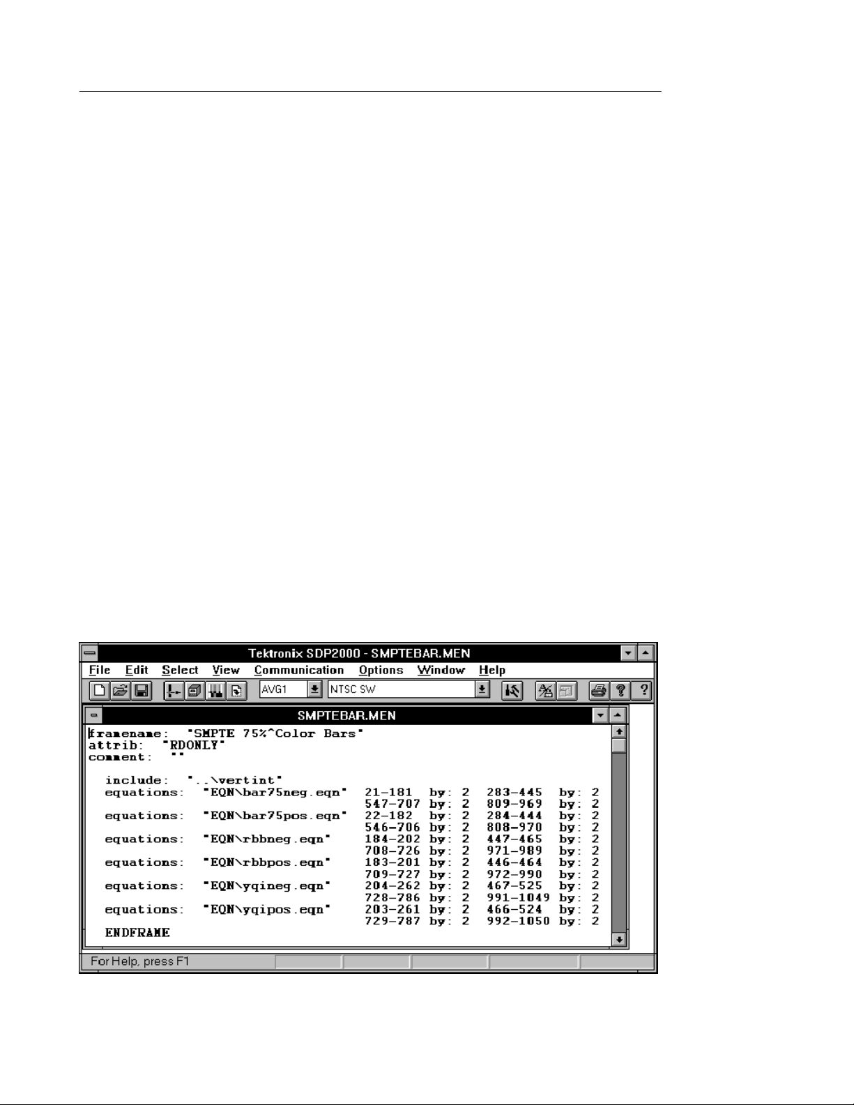
2. To use an existing file, copy a .men file from the SDP2000
directory and save it under a new file name. Figure 2 shows a
.men file for a software modulated signal.
Replace existing information with new information.
3. You can have multiple frame files open at the same time, and use
the Copy and Paste commands to copy lines of data between the
frame files.
4. If you have several lines of similar text, such as several
equations, use the Options menu to select a non-scaled font, such
as Courier, to make the text line up.
5. Save the File. Proceed to Building a Frame.
Figure 2: Sample Frame Fi le in the SDP2000 Frame Editor
SDP2000 User Manual
17
Page 22

Operating Basics
Building a Frame
1. Begin with the edited frame document (.men extension) open.
Save the document with a DOS file name. The SDP2000 adds the
.men extension.
2. Choose Build from the File menu, or use the build icon from the
toolbar. The SDP2000 automatically creates a compiled signal
file with the same name as the frame file you created, except the
extension is .cmp. Performing a Build automatically saves the
current .men file.
3. Proceed to Editing in the Graphic View of the Frame Editor.
Editing in the Graphic View of the Frame Editor
The graphic view allows you to view the video frame that you have
built and to make changes before sending this file to the Download
editor.
1. Switch to the graphic view using the text/graphics toolbar icon,
the Graphic View command from the View menu, or t he
keyboard shortcut, Ctrl + g.
2. A popup Field Select window appears; choose the field that you
want to view. The number of fields available depends on the
signal format. For example, NTSC is a four-field format. Two
fields are displayed at all times.
3. Using the View m enu, choose from three t ypes of graphic views:
Normal, Pulse Cross and Under Scan.
4. To edit in the graphic view, use the mouse along with the Copy
and Paste commands from the Edit menu. The status bar shows
the line range that you select with the mouse. Use the Tile
command from the Window menu to display all open files
without overlapping.
18
5. To open the Waveform edi tor for a select ed line, double click on
that line in the graphic view. Edit the equation file, save the
equation file, and then return to the frame file for further editing.
6. After editing in the graphic view, be sure that all included .eqn
files and .men files are saved, and then choose Build again.
SDP2000 User Manual
Page 23

Operating Basics
7. To add the .cmp file to a download file, go to Editing a
Download File on page 14.
Creating a New Waveform
It may be easiest to find an equation file (.eqn extension) that is
similar to the signal you want to create, and modify the signal. This
will retain the module and forma t information. However, you can
also begin with a new file and create an entirely new signal.
Touseanewfile:
1. Use the Open command from the File menu, limiting the file type
to .eqn files, or click on the Waveform editor icon in the toolbar.
2. Use the Module command from the Select menu to select the
TG2000 module for which the new signal will be designe d.
3. Use the Format command from the Select menu to select the
television format to which the new signal will adhere.
4. Proceed to Edit Equations.
To use an existing file:
1. For help in locating a file to edit, refer to SDP2000 File
Structure.
2. Open the equation file that you want to edit and use the Save As
command from the File menu to save the file with a new name.
3. Proceed to Edit Equations.
SDP2000 User Manual
19
Page 24

Operating Basics
Edit Equations
1. In the waveform file under edit, choose Equations from the Edit
menu to display the Edit Equations dialog box.
2. For multichannel formats only:
H Choose Channel to open the Select New Channel dialog box
H After editing one channel, choose Store Ch to save the
H Complete the following steps for each channel.
3. In the Edit Equations dialog box, choose Add. The Add Functions
dialog box appears.
and select the channel you want to edit.
changes you made before changing to a new channel. (If you
choose Switch, it will switch to the new channel without
saving the changes you made.)
4. In the Add Functions dialog box, select a term that you want t o
add to the waveform. Use the mouse or cursor keys to move
through the displayed boxes and enter the appropriate values for
the selected term. Some terms require a start and stop parameter.
Those terms will apply to only the portion of the waveform that
you specify. A Constant term always applies to the entire
waveform.
A # sign beside a box indicates that it is a sample box, contai ning
the number of samples equivalent to the value entered in its
companion box. When you select a sample box, its companion
box will appear highlighted in yellow. This indicates that a
change to either box changes the value in the other box.
5. To add the selected term, choose OK. The Edit Equations dialog
box reappears, and it displays a list of the term or terms that you
added. As you highlight a term in this list, the values you set for
the highlighted term are displayed along the right side of the
window, where you can edit them.
6. If you want to add another term, repeat steps 3 through 6.
20
7. In the Edit Equations dialog box, choose OK if you want to view
the new waveform graphically.
SDP2000 User Manual
Page 25

Operating Basics
8. If you want to multiply the term or terms you added by a multiply
function, choose Edit Equations again or double click anywhere
in the waveform display to return to the editing mode.
9. Highlight the term or terms that you want to multiply in the Edit
Equations dialog box and choose Multiply. The Multiply
Functions dialog box appears.
10. In the Multiply Functions dialog box, highlight the term by which
you want to multiply. Use the mouse or cursor keys to move
through the displayed parameters for the selec ted multiply term,
fill in the appropriate values and choose OK.
11. The Edit Equations dialog box is displayed, with the multiplier
that you selected appearing as a first-level term. The term or
terms it affects appear below it and indented, as second-level
terms. The entire equation appears in parentheses.
The multiplier cannot appear by itself; it must always be followed
by a second-level term. If you try to cut or de lete the underlying
terms, an error message appears. To remove the multiplier, first
copy and paste the second-level term into the equation by itself.
Select the original equation (including the parentheses) and delete
it.
12. If you want to multiply another term, repeat steps 10 through 12.
In the Edit Equations dialog box, choose OK if you want to view
the new waveform graphically.
13. If you want to apply an Other Function, choose Edi t Equations
again or double click anywhere in the waveform display to return
to the editing mode.
14. Highlight the term or terms to which you want to apply the
function, and choose Other Fxn. The Other Functions dialog box
appears.
15. In the Other Functions dialog box, select the function that you
want to apply. Use the mouse or cursor keys to move through the
displayed parameters for the selected multiply term, fill in the
appropriate values and choose OK.
16. The Edit Equations dialog box is displayed, with the other
function that you selected appearing as a first-level term.
SDP2000 User Manual
21
Page 26

Operating Basics
The term or terms it affects appear below it and indented, as
second-level terms. The entire equations appears in parentheses.
The Other function cannot appear by itself: it must always be
followed by a second-level term. If you try to cut or de lete the
underlying term, an error message appea rs. To remove the other
function, first copy and paste the second-level te rm i nto the
equation by itself. Next, select the original equation (including
the parentheses) and delete it.
17. When editing is complete, save the equation file. Note the
relative path name of the file.
18. Toaddthenewequationtoa.menfile,gotoUsing the Frame
Editor on page 16.
Edit Values
This is used for defining horizontal and vertical sync in digital
formats.
1. Open the equation file you want to edit, or open a new equation
file.
2. For multichannel formats only:
H Use the Select menu to choose the channel you want to edit.
H Complete the following steps for each channel that you want
to edit. (After editing the first channel, go to the Select menu
again and choose the next channel that you want to edit.)
3. Choose Equations from the Edit menu to display the Edit
Equations dialog box. Choose Add. The Add Funct ions dialog
box appears.
4. In the Add Functions dialog box, select Insert File. The SDP2000
creates an insert file with the same name as the equation file you
are editing, except the extension is .ins.
22
5. Choose OK. The Edit Equations dialog box reappears. Choose
OK in the Edit Equations dialog box.
SDP2000 User Manual
Page 27

Operating Basics
6. Choose Values from the Edit menu to open the Edit Values dialog
box. In the dialog box, select the sample point that you want to
edit, and type in a value.
7. To change the unit of measure, choose Amplitude Units in the
Options menu. (This also changes the amplitude units that are
displayed along the left side of the waveform display.)
8. Choose OK in the Edit Values dialog box. The changes to the
insert file are saved. The waveform display, with the new values,
is displayed. To change the time units along the bottom of the
display to sample units, choose Time Units from the Options
menu, then select Samples.
9. If you want to remove all of the changes you made to the values,
open the Edit Equations dialog box, highlight the Insert File term,
and delete it.
10. When editing is complete, save the equation file. Note the
relative path name of the file. This is what you will type in the
frame file before you build the frame.
11. Toaddthenewequationtoa.menfile,gotoUsing the Frame
Editor on page 16.
Creating a New Format
To create a new format, start with an existing format, modify it and
save it with a new format name. The new format can be used only
with the TG2000 module selected at the time you create the new
format.
Any changes you make are checked against limits for the selected
module. Excessive values are highlighted for you to change. If you
do not change them, they will be truncated when you save the
format.
1. Click on the Format editor icon in the toolbar.
2. Select the target module from the Select menu.
3. Select an existing format from the Select menu.
SDP2000 User Manual
23
Page 28

Operating Basics
4. Click in a field that you want to modify, such as sample
frequency or aspect ratio. Enter t he ne w value s and press Enter. If
the new value exceeds the capabilities of the target module, you
are prompted to enter a new value within the module limits.
Refer to the user manual for the TG2000 module to determine the
limits of a parameter.
5. Save the modified format with a new name. You can modify a
format that you saved previously, but not a factory format.
6. You can now select the new format in the Waveform editor or
Frame editor.
Deleting a Format
All formats that you create are saved in a file named userfmts.set.
To delete a format that you creat ed, open userfmts.set in a text
editor. Delete all text between the keyword .MODULE of the format
to be deleted and .MODULE of the next format, and save the file.
AWVG1 Generator Module Signals
The following two signal types apply only to the AWVG1 Generator
module. For more information, refer also to the AWVG1 Wideband
Video Generator User Manual.
Zone Plate Signals (AWVG1 Generator m odule only).To create a zone
plate signal using the SDP2000 program, do the following:
1. Select the AWVG1 module in the toolbar.
2. Open a .men file in the frame editor.
3. Select the Zone Plate Enable command from the Signal menu and
ensure that it is checked (enabled).
4. Select the Zone Plate Parameters command from the Signal
menu. This will open the Zone Plate Parameters dialog box.
Touch HELP to open a help window that tells you how to set the
parameters.
24
SDP2000 User Manual
Page 29

Operating Basics
In the Zone Plate Parameters dialog box, you can choose a
standard zone plate signal and modify it, or define your own
signal. You can also define the size and position of the window in
which the zone plate signal will appear. When you touch
QUIT/SAVE, the parameters that you selected are stored in the
.men file.
5. Build the frame. The graphic view will display the zone plate
signal when zone plate is enabled (step 3), and Fit In Window and
Normal are selected from the View menu.
6. The zone plate signal will appear within the defined window, in
the graphic view of the signal. If the zone plate signal does not
appear, be sure that zone plate enable is checked in the Signal
menu. If you select zone plate disable, the zone plate information
you stored in the .men file is still there, and will reappear when
you enable the zone plate signal again.
Frequency Markers (AWVG1 Generator module only). Horizontal and
field sweep signals can contain frequency marke rs. Horizont al sweep
signals can contain variable frequency markers; field sweep signals
support fixed markers only.
To set the frequency markers:
1. Select the AWVG1 module in the SDP2000 toolbar.
2. Open the .men file for a horizontal sweep signal (such as
/sdp/awvg1/525/1swp10.men) in the frame editor.
a. Select the Markers Enable com mand from the Signa l
menu and ensure that it is checked (markers enabled).
b. Select the Markers Parameters command from the Signal
menu. This will open the Markers Parameters dialog box.
c. In the Markers Parameters dialog box, you can choose
field or horizontal sweep. Choose horizontal sweep, and
then you can set the five adjustable frequency markers.
d. Touch HELP to open a help window tha t t ells you how to
set the parameters.
SDP2000 User Manual
25
Page 30

Operating Basics
3. Field sweep signals that have frequency markers have been
provided with the SDP2000 program. Open the .men file for a
field sweep signal (such as /sdp/awvg1/525/fldswp10.men)inthe
frame editor.
a. These are fixed markers. However, you can change the
sweep stop frequency, which will affect the marker
frequency. For example, if you start with a field sweep
signal that has a 0 to 30 MHz sweep and markers at 5, 10,
15, 20, and 25 MHz, and you change the sweep stop to 6
MHz, the markers will be at 1, 2, 3, 4, and 5 MHz.
b. Touch HELP to open a help window tha t tells you how to
set the parameters.
NOTE. If you want to create your own field sweep signal with
markers, begin with one of the field sweep signals in the SDP2000
signal library, and change the marker frequency by modifyi ng the
related .eqn and .men files. This task requires an advanced
knowledge of video signals.
4. When you touch QUIT/SAVE, the parameters that you selected
will be stored in the .men file.
5. Build the frame. The markers will appear within the zone plate
signal. If they do not appear, be sure that markers enabl e is
checked in the Signal menu (step a). If you select markers
disable, the marker information you stored in the .men file is still
there, and will reappear when you enable the markers again.
26
SDP2000 User Manual
Page 31

Appendix A: Remote Interface
This section describes the interfaces that can be used to transfer files
from the SDP2000 to the TG2000: Serial (RS232), Parallel, and 3.5”
floppy disk. Choose an interface method based on your available PC
port(s).
Serial Port (RS232)
The TG2000 Serial connector is a 9-pin, D-type connector with male
contacts, providing a standard RS232 interface. The location of the
Serial port is shown in Figure 3. Pin assignments are listed in
Table 1.
Serial Port
Parallel Port
Figure 3: TG2000 rear panel, showing the communication ports
To use the Serial interface, connect the 9-pin serial/RS232 output of
your PC to the 9-pin Serial connector on the rear panel of the
TG2000, using a 9-pin-to-9-pin straight-through cable. Be sure that
the CTS and RTS lines (pins 7 and 8 on the 9-pin serial connector)
are connected. If necessary, a 25-pin connector can be used, in
conjunction with a 9-pin-to-25-pin adapter (see Table 2).
GPIB
SDP2000 User Manual
27
Page 32

Appendix A: Remote Interface
From the Settings menu, choose Serial. Set the baud rate to match
the TG2000, and select an available computer port for communications (COM1, COM2, COM3, or COM4). On the TG2000, set the
Mode to Computer and the Flow Control to CTS/RTS.
Table 1: Pin assignments for TG2000 serial port
Pin number
1 Chassis Ground
2 RXD (Receive Data)
3 TXD (Transmit Data)
4 Not Used
5 GND (Signal Ground)
6 DSR (Data Set Ready)
7* RTS (Request to Send)
8* CTS (Clear to Send)
9 Not Used
Signal name
Table 2: 9-Pin-to-25-Pin Adapter Connections
DB9
pin number
TG2000
function
DB25
pin numberPCfunction
1 Chassis Ground Chassis Ground
2 RXD 3 TXD
3 TXD 2 RXD
4 Not Used
5 GND 7 GND
6 DSR 6
7* RTS 4 CTS
8* CTS 5 RTS
9 Not Used
* Must be connected in order to download signals.
28
SDP2000 User Manual
Page 33

Parallel Port
The TG2000 parallel connector is a 25-pin connector with male
contacts. The interface is Centronics compatible. The location of the
parallel connector is shown in Figure 3.
To use the parallel interface, connect the 25-pin parallel output of
your PC to the 25-pin PARALLEL connector on the rear panel of the
TG2000, using a standard 25-pin-to-25-pin straight-through cable.
From the Settings menu, choose Parallel. Select an available port (1,
2, or 3).
GPIB Port
The TG2000 GPIB i nterface conforms to IEEE Std. 488.1-1987 and
488.2-1987. The location of the GPIB connector is shown in
Figure 3.
Appendix A: Remote Interface
To use the GPIB interface, connect a GPIB cable between your PC
and the GPIB connector on the rear panel of the T G2000.
From the Settings menu, choose GPIB. Set the GPIB address to
match the address for your TG2000 Platform. (On the TG2000
Platform front-panel, push the Remote button, then touch GPIB setup
on the display to find the GPIB address.)
Floppy Drive
Signals from the SDP2000 can be stored on a 1.44 MB, 3.5 inch disk
and transmitted to the TG2000. This may be convenient when signals
are created at a central location, copied, and sent to many locations
where the TG2000 is used.
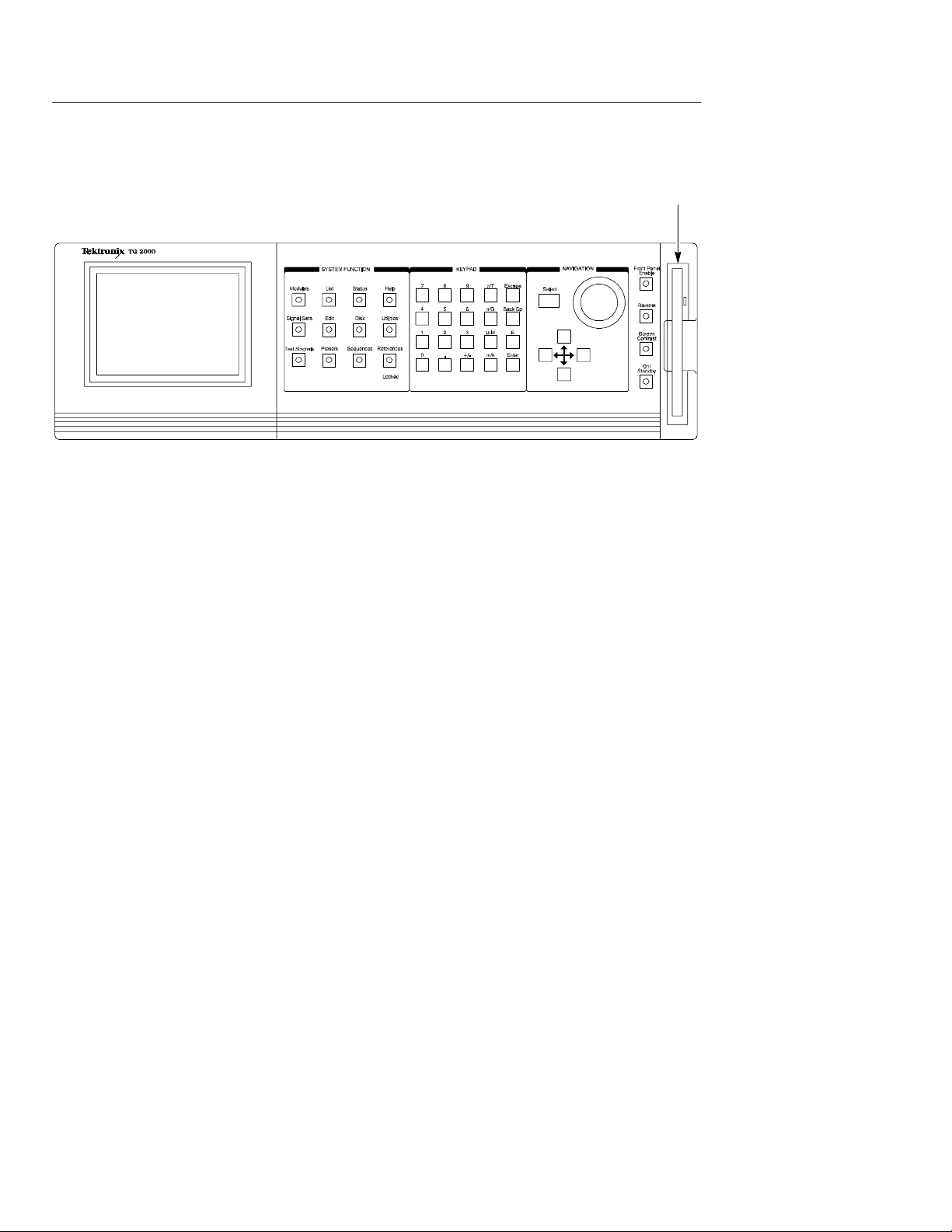
The TG2000 floppy drive is shown in Figure 4.
SDP2000 User Manual
29
Page 34
Appendix A: Remote Interface
Figure 4: TG2000 front panel
Floppy Drive
30
SDP2000 User Manual
Page 35

Appendix B: Field Codes
Standard Fields
Framename:
Type in a name for the frame. This name will appear in the download
file and on the screen of the TG2000. Type a caret symbol (^) to
separate lines (similar to a carriage return). Limit the name to three
lines or less. Spaces can be used.
Attrib:
Enter “RDWR” for read/write, or “RDONL Y” for read only.
Comment:
Enter comments that you want to appear in the Frame editor and the
Download editor. For example, in a multiburst signal, you could
enter the packet frequencies. The comment will not affect the signal.
Equations:
Type in the waveform file name and the line ranges to which it
applies. You can double click on any equation file name to ope n the
waveform editor.
Additional Codes:
#
Use a # to precede each line of a comment that you want to appear in
the Frame editor only. The comment will not affect the signal.
SDP2000 User Manual
31
Page 36

Appendix B: Field Codes
by:x
Type this code to apply the equation to the x line, and every line that
is a multiple of x.
Include:
Type in the name of another .men file that you want to include.
Typing in the .men extension is optional. For example: “VERTINT”
or “VERTINT .MEN”. Note that VERTINT could also reference
another equation file, and so forth.
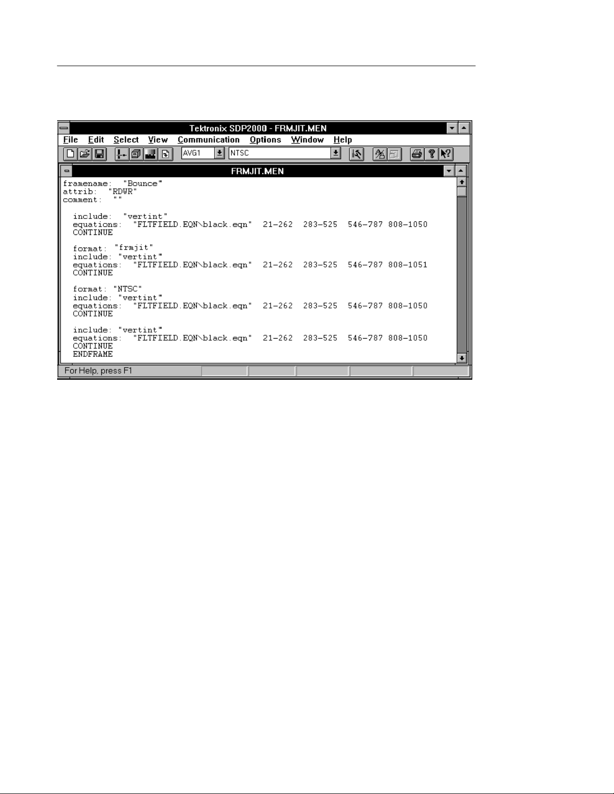
Format:
The format code is used to change the television format for one field
or frame. This controls only the vertical aspec t of the fiel d or frame;
the equation file controls the horizontal aspect. Figure 5 shows a
sample file called \SDP2000\AVG1\SAMPLE\FRMJIT.MEN. This
file uses the Format code to insert frame jitter (it inserts an extra line
in one of the four frames).
ENDFRAME
All frame files must end with this code, unless they are continued to
another file. If the file is continued, only the last file in the sequence
must end with this code.
CONTINUE
This code is used with the ENDFRAME code for continued files.
Continued frames are used to create motion. The Continue code is
used in the frame file shown in Figure 5.
32
SDP2000 User Manual
Page 37
Appendix B: Field Codes
Figure 5: Sample Frame Fi le
SDP2000 User Manual
33
Page 38

Appendix B: Field Codes
34
SDP2000 User Manual
Page 39

Index
C
Communications, 8
Compiled signals, 8
Context-sensitive help, 5
Creating a new format, 23
D
Deleting a format, 24
Deleting signals, 14
Digital formats, see Edit Values, 22
Displaying TG2000 signals, 13
Download editor, 8
creating a new download file, 15
editing download files, 14
Download files, 8
download file structure, 9
sample file, 9
Downloading files, 12
editing in the text mode, 17
Frequency markers, 25
G
General interface, 11
GPIB communications, 13
I
Installation procedure, 3
M
Markers, 25
Menu files, 9
O
E
Editing equation files, see Creating
a New W aveform, 19
Equation files, 9, 19
F
File types, 8
Format editor, 7
creating a new format, 23
deleting a format, 24
Frame editor
building a frame, 18
editing frame files, 16
editing in the graphic view, 18
SDP2000 User Manual
Online help, 5
P
Parallel communications, 12
R
Remote communications, 12
Removing the software, 5
S
SDP2000 functions, 1
Serial communications, 12
Source files, 8
35
Page 40

Index
System requirements, 2
T
Technical assistance, 6
TGCOMM display, 13
TGCOMM functions, 1
Tutorials, 12
U
Uninstall, see Removing the Soft-
ware, 5
Userfmts.set, 24
Using the SDP2000, 5
W
W aveform editor, 7
creating a new waveform, 19
Edit Equations dialog box, 20
Edit Values dialog box, 22
Z
Zone plate signals, 24
36
SDP2000 User Manual
 Loading...