

Page 1

Service Manual
SDA601
Serial Digital Analyzer
070-8914-04
Warning
The servicing instructions are for use by qualified
personnel only. To avoid personal injury, do not
perform any servicing unless you are qualified to
do so. Refer to all safety summaries prior to
performing service.
www.tektronix.com
Page 2

Copyright © Tektronix, Inc. All rights reserved. Licensed software products are owned by Tektronix or its subsidiari es or
suppliers, and are protected by national copyright laws and international treaty provisions.
Tektronix products are covered by U.S. and foreign patents, issued and pending. Information in this publication supercedes
that in all previously published material. Specifica tions and price change privileges reserved.
TEKTRONIX and TEK are registered trademarks of Tektronix, Inc.
Contacting Tektronix
Tektronix, Inc.
14200 SW Karl Braun Drive
P.O. Box 500
Beaverton, OR 97077
USA
For product information, sales, service, and technical support:
H In North America, call 1-800-833-9200.
H Worldwide, visit www.tektronix.c om to find contacts in your area.
Page 3

Warranty 2
Tektronix warrants that this product will be free from defects in materials and workmanship for a period of one (1) year
from the date of shipment. If any such product proves defective during this warranty period, Tektronix, at its option, either
will repair the defective product without charge for parts and labor, or will provide a replacement in exchange for the
defective product. Parts, modules and replacement products used by Tektronix for warranty work may be new or
reconditioned to like new performance. All replaced parts, modules and products become the property of Tektronix.
In order to obtain service under this warranty, Customer must notify Tektronix of the defect before the expiration of the
warranty period and make suitable arrangements for the performance of service. Customer shall be responsible for
packaging and shipping the defective product to the service center designated by Tektronix, with shipping charges prepaid.
Tektronix shall pay for the return of the product to Customer if the shipment is to a location within the country in which the
Tektronix service center is located. Customer shall be responsible for paying all shipping charges, duties, taxes, and any
other charges for products returned to any other locations.
This warranty shall not apply to any defect, failure or damage caused by improper use or improper or inadequate
maintenance and care. Tektronix shall not be obligated to furnish service under this warranty a) to repair damage resulting
from attempts by personnel other than Tektronix representatives to install, repair or service the product; b) to repair
damage resulting from improper use or connection to incompatible equipment; c) to repair any damage or malfunction
caused by the use of non-Tektronix supplies; or d) to service a product that has been modified or integrated with other
products when the effect of such modification or integration increases the time or difficulty of servicing the product.
THIS WARRANTY IS GIVEN BY TEKTRONIX WITH RESPECT TO THE PRODUCT IN LIEU OF ANY OTHER
WARRANTIES, EXPRESS OR IMPLIED. TEKTRONIX AND ITS VENDORS DISCLAIM ANY IMPLIED
WARRANTIES OF MERCHANTABILITY OR FITNESS FOR A P ARTICULAR PURPOSE. TEKTRONIX’
RESPONSIBILITY TO REP AIR OR REPLACE DEFECTIVE PRODUCTS IS THE SOLE AND EXCLUSIVE REMEDY
PROVIDED TO THE CUSTOMER FOR BREACH OF THIS WARRANTY. TEKTRONIX AND ITS VENDORS WILL
NOT BE LIABLE FOR ANY INDIRECT, SPECIAL, INCIDENTAL, OR CONSEQUENTIAL DAMAGES
IRRESPECTIVE OF WHETHER TEKTRONIX OR THE VENDOR HAS ADVANCE NOTICE OF THE POSSIBILITY
OF SUCH DAMAGES.
Page 4

Page 5

Table of Contents
Specifications
Operating Information
General Safety Summary vii...................................
Service Safety Summary ix....................................
Introduction 1--1.....................................................
Reference Documentation 1--1..........................................
Performance Conditions 1--1...........................................
Specification Tables 1--2..............................................
Certifications and Compliances 1--4.....................................
Getting Started 2--1..................................................
Supplying Power 2--1.................................................
Connecting the SDA601 2--3...........................................
SERIAL INPUT 2--4..............................................
AUX Output 2--4.................................................
RS-232 Interface 2--4.............................................
Keypad and Display Conventions 2--8....................................
The On-Screen Display (OSD) 2--9......................................
Preliminary Settings 2--10..............................................
Set the Date and Time 2--10.........................................
Set the Battery Type 2--11...........................................
Enable (Disable) Auto Power Off 2--11................................
Disable (Enable) Timed LCD Backlight Turn Off 2--12....................
Performance Verification 2--12..........................................
Using Your SDA601 2--12..............................................
Analyzing a Signal 2--13............................................
Watching a Signal 2--15............................................
Alarms 2--19.....................................................
LCD Display Modes 2--20..........................................
AUX Output Modes 2--23...........................................
Saving and Recalling Presets 2--25....................................
Software Reset 2--26...............................................
Performance Verification
Required Test Equipment 3--1..........................................
Performance Verification Checklist 3--3..................................
Performance Verification Procedures 3--4.................................
Adjustment Procedures
Required Test Equipment 4--1..........................................
Adjustment Procedures 4--2............................................
SDA 601 Serial Digital Analyzer
Preparation 3--4..................................................
Procedures 3--6..................................................
i
Page 6

Table of Contents
Maintenance
Adjust SLM (Signal Level Meter) 4--2................................
Adjust the Deserializer VCO (“Serial Pot”) 4--4.........................
Set the Date and Time 4--7.........................................
Maintenance 5--1..............................................
Battery Hints 5--1....................................................
Preventive Maintenance 5--1...........................................
Cleaning 5--1....................................................
Static-Sensitive Components 5--2....................................
Troubleshooting Aids 5--3.............................................
Foldout Pages 5--3................................................
Diagrams 5--3...................................................
Circuit Board Illustrations 5--3......................................
Numbering 5--3..................................................
Self-Diagnostics 5--4..............................................
Corrective Maintenance 5--9...........................................
Obtaining Replacement Parts 5--9....................................
Torque Specification 5--9..........................................
Replacing Assemblies 5--10.........................................
Replaceable Electrical Parts
Replaceable Electrical Parts 6--1.................................
Parts Ordering Information 6--1.........................................
Using the Replaceable Electrical Parts List 6--1............................
Abbreviations 6--1................................................
List of Assemblies 6--2............................................
Column Descriptions 6--2..............................................
Replaceable Electrical Parts 6--4........................................
Diagrams
Diagrams and Circuit Board Illustrations 7--1.....................
Block Diagrams 7--1.................................................
Circuit Board Illustrations 7--3..........................................
Replaceable Mechanical Parts
Replaceable Mechanical Parts 8--1...............................
Parts Ordering Information 8--1.........................................
Using the Replaceable Mechanical Parts List 8--1...........................
Abbreviations 8--1................................................
Chassis Parts 8--2................................................
Column Descriptions 8--2..............................................
Replaceable Mechanical Parts 8--3.......................................
Index
ii
SDA 601 Serial Digital Analyzer
Page 7

List of Figures
Table of Contents
Figure 2--1: Opening the Battery Compartment 2--2.................
Figure 2--2: Connecting the SDA601 2--3..........................
Figure 2--3: Connecting to a DTE Device with a DB25 Serial Port 2--5..
Figure 2--4: Connecting to a DCE Device with a DB25 Serial Port 2--6.
Figure 2--5: A Printed Analysis Report 2--7........................
Figure 2--6: The Default “Watching” OSD 2--9.....................
Figure 2--7: The Initial SDA601 Utility Menu Display 2--10............
Figure 2--8: The Set Time Display 2--10............................
Figure 2--9: Front and side views 2--13.............................
Figure 2--10: The Analyze OSD 2--14..............................
Figure 2--11: The Initial SDA601 Utility Menu Display 2--16...........
Figure 2--12: The SDA601 “Watching” Display 2--17.................
Figure 2--13: Watch Errors Reported on the OSD 2--18...............
Figure 2--14: The Display Mode Selection Keys 2--21.................
Figure 2--15: The SDA601 Signal Level Display 2--21.................
Figure 2--16: The Cursor Data Display 2--22........................
Figure 2--17: The SDA601 Time Display 2--23.......................
Figure 2--18: The First Review Display 2--23........................
Figure 3--1: An Equipment Setup for Performance Verification 3--4...
Figure 3--2: AUX Output Containing the On-Screen Display (OSD) 3--5
Figure 3--3: The Initial SDA601 Utility Menu Display 3--6............
Figure 3--4: The TSG601 Display Indicating Normal CRCs 3--7.......
Figure 3--5: The Analyze OSD 3--8...............................
Figure 3--6: The TSG601 Display Indicating an Erroneous FFCRC 3--9
Figure 3--7: The TSG601 Display Indicating an Erroneous APCRC 3--9
Figure 3--8: The TSG601 Display Indicating a Zero APCRC 3--10......
Figure 3--9: The SDA601 Cursor Display 3--11......................
Figure 3--10: The First Watch Menu Display 3--12...................
Figure 3--11: The I/O Menu/Highlighting Item Display 3--12...........
Figure 3--12: Page Five of the Watching OSD 3--15...................
Figure 3--13: SDA601-to-PC Cable Connections 3--16................
Figure 3--14: Initial Return Loss Setup 3-- 17........................
Figure 4--1: A Setup for SLM Adjustment 4--2.....................
Figure 4--2: The First SLM Calibration Display 4--3.................
SDA 601 Serial Digital Analyzer
iii
Page 8

Table of Contents
Figure 4--3: A Setup for Adjusting the De-serializer VCO 4--5........
Figure 4--4: The “Adj Serial Pot” Menu Item 4--5...................
Figure 4--5: The VCO Lock Error Indicator 4--6....................
Figure 4--6: The “Set Time” Display 4--7..........................
Figure 5--1: Numeric SLM Data 5--7..............................
Figure 5--2: The SDA Number Keys 5--7...........................
Figure 5--3: Exploded View of the SDA601 5--10.....................
iv
SDA 601 Serial Digital Analyzer
Page 9

List of Tables
Table of Contents
Table 1--1: Serial Digital Video Input 1--2.........................
Table 1--2: Signal Level Meter 1--2...............................
Table 1--3: AUX Output 1--2.....................................
Table 1--4: Power Supply 1--2...................................
Table 1--5: Physical Characteristics 1--3...........................
Table 1--6: Environmental Characteristics 1--3.....................
Table 2--1: RS-232 Connector Pin Assignments 2--5.................
Table 3--1: Required Test Equipment 3--1.........................
Table 3--2: Initial Settings for the Video Measurement Set 3--5.......
Table 4--1: Required Test Equipment 4--1.........................
SDA 601 Serial Digital Analyzer
v
Page 10

Page 11

General Safety Summary
Review the following safety precautions to avoid injury and prevent damage to
this product or any products connected to it.
To avoid potential hazards, use this product only as specified.
Only qualified personnel should perform service procedures.
ToAvoidFireor
Personal Injury
Use Proper Power Cord. Use only the power cord specified for this product and
certified for the country of use.
Connect and Disconnect Properly. Do not connect or disconnect probes or test
leads while they are connected to a voltage source.
Ground the Product. This product is grounded through the grounding conductor
of the power cord. To avoid electric shock, the grounding conductor must be
connected to earth ground. Before making connections to the input or output
terminals of the product, ensure that the product is properly grounded.
Observe All Terminal Ratings. To avoid fire or shock hazard, observe all ratings
and markings on the product. Consult the product manual for further ratings
information before making connections to the product.
Do not apply a potential to any terminal, including the common terminal, that
exceeds the maximum rating of that terminal.
Power Disconnect. The power cord disconnects the product from the power
source. Do not block the power cord; it must remain accessible to the user at all
times.
Do Not Operate Without Covers. Do not operate this product with covers or panels
removed.
Do Not Operate With Suspected Failures. If you suspect there is damage to this
product, have it inspected by qualified service personnel.
SDA 601 Serial Digital Analyzer
Avoid Exposed Circuitry. Do not touch exposed connections and components
when power is present.
Replace Batteries Properly. Replace batteries only with the specified type and
rating.
Recharge Batteries Properly. Recharge batteries for the recommended charge
cycle only.
Use Proper AC Adapter. Use only the AC adapter specified for this product.
Use Proper Fuse. Use only the fuse type and rating specified for this product.
Do Not Operate in Wet/Damp Conditions.
vii
Page 12
General Safety Summary
Do Not Operate in an Explosive Atmosphere.
Keep Product Surfaces Clean and Dry.
Terms in this Manual
Symbols and Terms
These terms may appear in this manual:
WARNING. Warning statements identify conditions or practices that could result
in injury or loss of life.
CAUTION. Caution statements identify conditions or practices that could result in
damage to this product or other property.
These terms may appear on the product:
H DANGER indicates an injury hazard immediately accessible as you read the
marking.
H WARNING indicates an injury hazard not immediately accessible as you
read the marking.
H CAUTION indicates a hazard to property including the product.
The following symbols may appear on the product:
viii
CAUTION
Refer to Manual
SDA 601 Serial Digital Analyzer
Page 13

Service Safety Summary
Only qualified personnel should perform service procedures. Read this Service
Safety Summary and the General Safety Summary before performing any service
procedures.
Do Not Service Alone. Do not perform internal service or adjustments of this
product unless another person capable of rendering first aid and resuscitation is
present.
Disconnect Power. To avoid electric shock, switch off the instrument power, then
disconnect the power cord from the mains power.
Use Care When Servicing With Power On. Dangerous voltages or currents may
exist in this product. Disconnect power, remove battery (if applicable), and
disconnect test leads before removing protective panels, soldering, or replacing
components.
To avoid electric shock, do not touch exposed connections.
SDA 601 Serial Digital Analyzer
ix
Page 14

Environmental Considerations
This section provides information about the environmental impact of the
product.
Product End-of-Life
Handling
Observe the following guidelines when recycling an instrument or component:
Equipment Recycling. Production of this equipment required the extraction and
use of natural resources. The equipment may contain substances that could be
harmful to the environment or human health if improperly handled at the
product’s end of life. In order to avoid release of such substances into the
environment and to reduce the use of natural resources, we encourage you to
recycle this product in an appropriate system that will ensure that most of the
materials are reused or recycled appropriately.
The symbol shown to the left indicates that this product
complies with the European Union’s requirements
according to Directive 2002/96/EC on waste electrical and
electronic equipment (WEEE). For information about
recycling options, check the Support/Service section of the
Tektronix Web site (www.tektronix.com).
Battery Recycling. This product may contain a Nickel Cadmium (NiCd)
rechargeable battery, which must be recycled or disposed of properly. Please
properly dispose of or recycle the battery according to local government
regulations.
Restriction of Hazardous
Substances
x
This product has been classified as Monitoring and Control equipment, and is
outside the scope of the 2002/95/EC RoHS Directive. This product is known to
contain lead, cadmium, mercury, and hexavalent chromium.
SDA 601 Serial Digital Analyzer
Page 15

Specifications
Page 16

Page 17

Specifications
Introduction
The material in this section is organized into two main groupings: the specification tables and the supporting figures. The specification tables include:
H General input and output signal characteristics and specifications
H Physical and environmental specifications
The supporting figures (waveform diagrams and related data) follow the
specification tables.
Reference Documentation
The following documents were used as references in the preparation of these
specifications:
Recommendations and Reports of the CCIR, 1978; Transmission of Sound
Broadcasting and Television Signals Over Long Distances (CMTT).
Performance Conditions
The Performance Requirements are valid if the instrument has been adjusted at
approximately 25° C, is being operated within environmental limits (see
Table 1--3), and has had a minimum warm-up of 20 minutes.
IEEE Standard Dictionary of Electrical Terms, Second Edition (1977)
IEEE Standard 100--1977.
IEC 60B (Secretariat) 170, “Helical-scan digital composite cassette recording
system using 19 mm magnetic tape (Format D--2) (NTSC, PAL, PAL-M).”
ANSI/ISA S82 — Safety Standard for Electrical and Electronic Test,
Measuring, controlling, and Related Equipment.
CAN/CSA C22.2 No. 1010.1-92 — Safety Requirements for Electrical
Equipment for Measurement, control, and Labratory Use.
IEC1010-1 — Safety Requirements for Electrical Equipment for Measurement, Control, and Laboratory Use (1990).
SDA 601 Serial Digital Analyzer 1--1
Page 18
Specifications
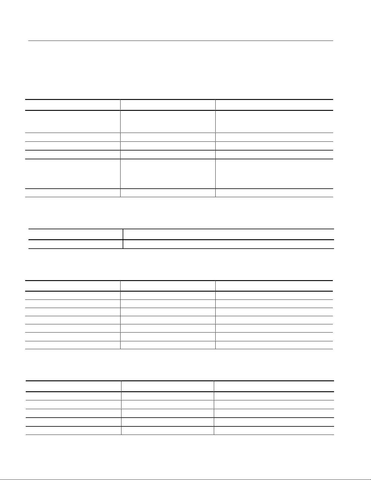
Specification Tables
Table 1--1: Serial Digital Video Input
Characteristic Performance Requirements Supplemental Information
Format CCIR 601 Component 525/625, 10 bits data,
Scrambled NRZI; 270 Mb/s. Complies with SMPTE
259M and CCIR 656.
Input Impedance 75 Ω
Input Level 800 mV ± 80 mV (peak-to-peak) at signal source
Return Loss ≥ 15dB 1 MHz to 270 MHz
Serial Receiver Equalization Range Proper operation with 800 mV launch
amplitude and up to 15 dB loss at
135 MHz using coaxial cable with 1?
loss characteristics.
Error detection protocols supported EDH (RP-165), ØAPCRC
Nominally 150 m of Belden 8281 coaxial cable;
typically up to 200 m.
Ꭹ
f
Table 1--2: Signal Level Meter
Characteristic Information
Resolution 2 dB @ 135 MHz
Table 1--3: AUX Output
Characteristic Performance Requirements Supplemental Information
Output 5-bit output; monochrome signal
White Amplitude 700 mV ± 10% Terminated into 75 Ω
Sync Amplitude 300 mV ± 10% Terminated into 75 Ω
DC Offset ≤ 500 mV Terminated into 75 Ω
Quantization 22 mV
Impedance 75 Ω nominal
Return Loss ≥ 10 dB to 10 MHz
Table 1--4: Power Supply
Characteristic Performance Requirements Supplemental Information
DC Input Range 9to15Vdc ≥12 V required to charge optional battery pack
Supply Accuracy +5 V ±250 mV
Hum Typical: 25 mV
Noise ≤ 50 mV
Fuse 2 A slow blow, 32 V min
1--2 SDA 601 Serial Digital Analyzer
Page 19
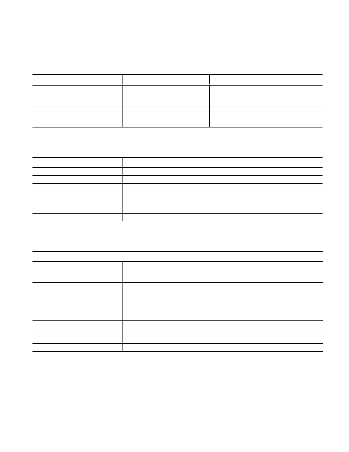
Table 1--4: Power Supply (Cont.)
Power Limit
without adapter
with adapter
Power Consumption
Back light off
Back light on
Table 1--5: Physical Characteristics
Characteristic Information
Height 5.6 cm (2.2 in)
Width 9.1 cm (3.6 in)
Depth 19.1 cm (7.5 in)
Net Weight
SDA 601
SDA 601 with battery pack
Shipping Weight (with AC adapter) 1.50 kg (3.31 lb)
0.48 kg (1.06 lb)
0.68 kg (1.5 lb)
Specifications
Supplemental InformationPerformance RequirementsCharacteristic
6W
7W
Typical:
5.0 W
5.5 W
Table 1--6: Environmental Characteristics
Characteristic Information
Temperature
Operating
Storage
Altitude
Operating
Storage
Equipment Type Tes t
Equipment Class Class III (as defined in IEC 1010-1, Annex H)
Installation Category Category II (as defined in IEC 1010-1, Annex J)
Pollution Degree Pollution Degree 2 (as defined in IEC 1010-1)
Transportation Meets the requirements of NTSB Test Procedure 1A, category II (24 inch drop)
0° Cto+35° C (32° Fto+95° F)
-- 3 0 ° Cto+65° C(--22° F to +149° F)
to 15,000 feet (4572 m); IEC 1010-1 compliance to 2000 m
to 50,000 feet (15420 m)
Note: Rated for indoor use only.
SDA 601 Serial Digital Analyzer
1--3
Page 20

Specifications
Certifications and Compliances
EC Declaration of
Conformity -- EMC
Meets intent of Directive 89/336/EEC for Electromagnetic Compatibility.
Compliance was demonstrated to the following specifications as listed in the
Official Journal of the European Communities:
EN 55103. Product family standard for audio, video, audio-visual and entertainment lighting control apparatus for professional use.
H Environment E2 — commercial and light industrial
H Part 1 Emission
H EN 55022. Class B radiated and conducted emissions
H EN 55103--1 Annex A. Radiated magnetic field emissions
H EN 55103--1 Annex B. Inrush current
H Part 2 Immunity
H IEC 61000--4--2. Electrostatic discharge immunity
H IEC 61000--4--3. RF electromagnetic field immunity
H IEC 61000--4--4. Electrical fast transient / burst immunity
Australia / New Zealand
Declaration of Conformity
-- E M C
EMC Compliance
H IEC 61000--4--5. Power line surge immunity
H IEC 61000--4--6. Conducted RF Immunity
H IEC 61000--4--11. Voltage dips and interruptions immunity
H EN 55103--2 Annex A. Radiated magnetic field immunity
EN 61000--3--2. AC power line harmonic emissions
Complies with EMC provision of Radiocommunications Act per these standard(s):
H AS/NZS 2064.1/2. Industrial, Scientific, and Medical Equipment: 1992
Meets the intent of Directive 89/336/EEC for Electromagnetic Compatibility
when it is used with the product(s) stated in the specifications table. Refer to the
EMC specification published for the stated products. May not meet the intent of
the directive if used with other products.
1--4
SDA 601 Serial Digital Analyzer
Page 21

Operating Information
Page 22

Page 23
Operating Information
This section duplicates material contained in the SDA601 user manual
(Tektronix p/n 070-8910-XX). The material is included here for your convenience. Please check the user manual whenever you need more information on
any topic.
Getting Started
Please note the following statements before using your SDA601.
CAUTION. Attempting to operate the SDA601 with an improper AC-to-DC adapter can result in damage to the instrument. To avoid damage, USE ONLY AN APPROPRIATE DC POWER SOURCE: Voltage must be 9 to 15 VDC; the
connector must have the NEGATIVE contact in the center; and open-circuit voltage of the power source must not exceed 18 VDC.
For best results, use the AC adapter that is supplied with the instrument. If the
supplied adapter is incorrect for the local AC power supply, contact your nearest
T ektronix representative.
Supplying Power
WARNING. Install or replace batteries only with the instrument switched OFF
and the AC adapter disconnected.
Replace the batteries only with standard AA batteries (1.2--1.5 V, nominal), or
with a Tektronix rechargeable battery pack (p/n 119-4488-00).
If you have any questions regarding the operation of this instrument, please
contact your nearest Tektronix representative or field office. In the United States
and Canada, you may also call the Tektronix information number, 1-800-TEKWIDE (1-800-835-9433), extension TV, between 8:00 am and 5:00 pm Pacific
time.
The SDA601 is DC powered. You may power it with the standard AC adapter,
the optional 9.6 V NiCad battery pack, eight standard AA batteries, or a “BP”
type external battery pack with the correct voltage and polarity. The external DC
power connector is on the left side of the instrument.
SDA 601 Serial Digital Analyzer 2- 1
Page 24
Operating Information
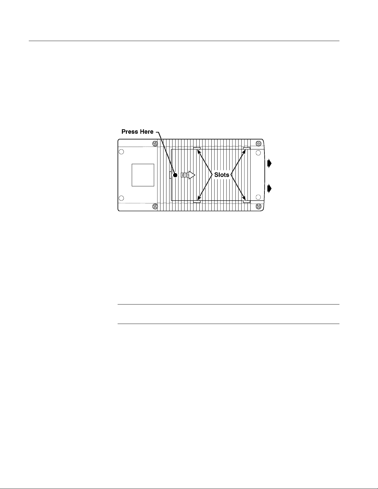
To install AA batteries or the battery pack, open the battery compartment of the
SDA601 by pressing down on the cover and sliding it in the direction of the
inscribed arrow, as shown in Figure 2--1. When the cover tabs line up with the
slots in the case, lift the cover away from the instrument. Install batteries in
alternating directions as indicated by the graphic molded into the “floor” of the
battery compartment. If using the optional battery pack, take the time to identify
both contacts and install the pack properly.
Figure 2- 1: Opening the Battery Compartment
When selecting a power source for your SDA601, please remember:
H Attempting to use an improper AC adapter can cause permanent damage to
the instrument. USE AN APPROPRIATE DC POWER SOURCE ONLY:
Voltage must be between 9 and 15 VDC; the center contact of the connector
must be NEGATIVE polarity; and open-circuit voltage must not exceed 18
VDC. For best results, use the adapter supplied with the instrument.
NOTE. Batteries must be installed to ensure uninterrupted operation when using
the wall adapter.
H There is no need to remove the optional NiCad battery pack for recharging.
The SDA601 will “trickle charge” the battery pack whenever the standard
AC adapter is attached and the instrument is switched off. It can take up to
16 hours to fully charge the battery pack. Note that charging w ill occur only
if the adapter supplies at least 12V; make sure that the adapter you use is
appropriate for the local AC supply.
H AA batteries are not included with the instrument; buy them locally.
Rechargeable AA batteries may be used, but they are NOT recharged
automatically. To recharge AA batteries, remove them from the instrument
and use an appropriate charger. For safety, read and follow the battery
charger instructions. Do NOT attempt to recharge standard alkaline batteries.
2- 2 SDA 601 Serial Digital Analyzer
Page 25

Operating Information
H After three minutes with no key press, the LCD back light will be dimmed to
save battery charge. (This may be disabled through the Utility/Diagnostics/
Power Manage menu; see page 2--12.)
H To guard against battery discharge if you forget to turn the SDA601 off,
enable Auto Power Off through the Utility/Diagnostics/Power Manage menu
(see page 2--11).
H The SDA601 can sense low battery voltage. It will warn you when the
charge is sufficient for approximately ten more minutes of operation. The
instrument will shut itself down when the battery voltage becomes too low
for reliable operation
The ON key toggles instrument power On and Off.
NOTE. If the instrument is operating with low batteries, it may turn itself off and
on. The batteries should be replaced or recharged depending on battery types.
Connecting the SDA601
Figure 2- 2: Connect ing the SDA601
Connect the instrument as shown in Figure 2--2. The OPTION connector is
reserved for later versions of the instrument. Note that the SDA601 has many
capabilities and features, and you may wish to gain familiarity with it by first
connecting it directly to a serial digital, component video signal generator such
as the Tektronix TSG601, an analog video monitor, and—if convenient—a
compact printer, such as the Seiko DPU 411 printer (Tektronix part number
119-4594-00), available from Tektronix distributors and through TekDirect.
SDA 601 Serial Digital Analyzer 2- 3
Page 26

Operating Information
SERIAL INPUT
AUX Output
Connect the instrument to your system through the SERIAL INPUT with 75Ω
coaxial cable.
NOTE. The SDA601 has internal, active termination. Any signal path that ends
with the instrument will be properly terminated only when the SDA601 is
switched on.
The AUX output signal may be thought of as “pseudo video.” It is derived from
the serial video input signal and converted to composite monochrome analog
video by an unfiltered 5-bit DAC. It is suitable for identifying the input and
displaying the cursor cross hairs, Highlighting, and the “OSD.” It:
H Lets you view the picture for convenient source identification.
H Can contain the On-screen Display (OSD; see page 2--9), which shows the
most recent Watch or Analyze results one page at a time—instead of one
item at a time as on the SDA601 display.
H With Pulse Cross enabled (see page 2--24), lets you “see” the contents of the
vertical and horizontal interval portions of the serial video signal.
RS-232 Interface
H Can include Cursor cross hairs for convenient positioning of the Cursors (see
page 2--22).
H When Highlighting (see page 2--24) is turned on, can help you locate and
identify errors in the picture, or the digital encoding of the signal.
By factory default, the AUX output is the Y (luminance) video component; you
may configure it, through the I/O menu, to be the R–Y or B–Y component
instead. (To access this setting, press
Connect an ASCII, serial printer to the RS-232 connector to create “hard copy”
analysis reports, or to log errors detected during a Watch session. You may also
capture the RS-232 output on a personal computer running a communications
application such as PROCOMMR or the Terminal accessory of MicrosoftR
WindowsT. With a printer or PC connected, you can choose—through the Alarm
menu—to have the SDA601 log every error as it occurs, or to print a Watch
report every ten seconds. This will permit unattended monitoring of your system.
See page 2--19 for more information.
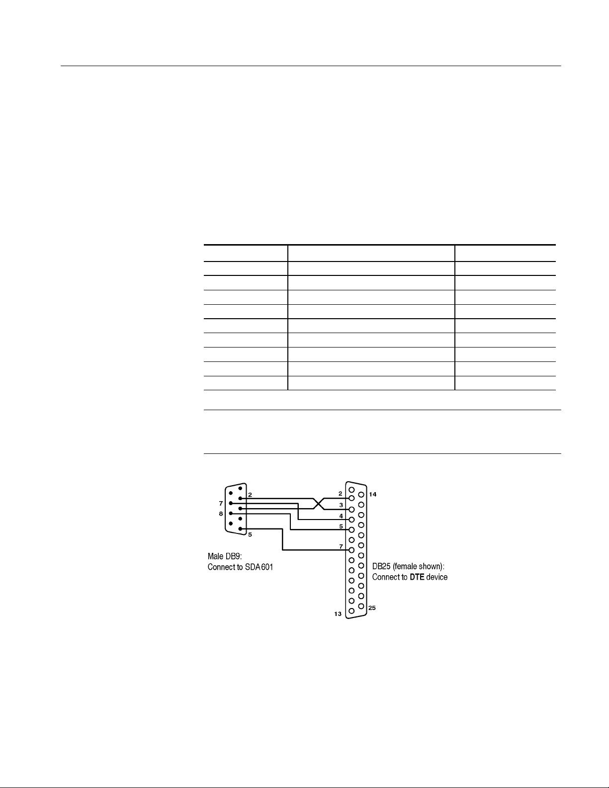
Connecting to the RS-232 Port. The SDA601 is an RS-232 DCE device. Table
2--1 lists the pin assignments of the connector. The connector pinout has been
chosen to interface directly with an IBM PC/AT 9-pin serial port using a
straight-through cable. Thus, when communicating with a DTE device that has a
male 9-pin (DB9) connector, use a cable that connects pins 2, 3, 5, 7, and 8
Shift, then Insert On/Off, then Y.)
2- 4 SDA 601 Serial Digital Analyzer
Page 27
Operating Information
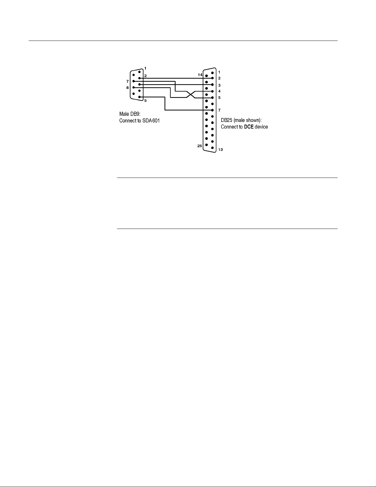
straight-through—a simple ribbon cable may be adequate. Use a null modem
cable (which swaps the lines between pins 2 and 3 and pins 7 and 8) to communicate with another DCE device. Figures 2--3 and 2--4 illustrate cable wiring for
communicating with a device that has a 25-pin serial connector.
Because of space limitations on the connector end of the SDA601, you may
have to insert a 9-pin adapter between the cable and the connector. If the cable
has a female end, use a male/male adapter such as ITT Cannon p/n 111805--1.
Table 2- 1: RS-232 Connector Pin Assignments
764 DB9 Pin Signal Name Signal Direction
1 Not connected —
2 RXD (Received Data) From SDA601
3 TXD (Transmitted Data) To SDA601
4 Not connected —
5 Signal Ground —
6 Not connected —
7 RTS (Request to Send) To SDA601
8 CTS (Clear to Send) From SDA601
9 Not connected —
NOTE. RS-232 signals are named from the perspective of the DTE device. Since
the SDA601 is a DCE device, pin 2 (“Received Data”) is an output from the
instrument; that is, the data is received by the connected DTE device.
Figure 2- 3: Connect ing to a DTE Device with a DB25 Serial Port
SDA 601 Serial Digital Analyzer 2- 5
Page 28
Operating Information
Figure 2- 4: Connect ing to a DCE Device with a DB25 Serial Port
NOTE. Most Personal Computers are DTE devices; however, printers may be
either DTE or DCE, and the type may not be obvious from the printer documentation or the gender of the RS-232 connector. If you have trouble outputting from
the SDA601, first verify that communication parameter and Baud rate settings
are correct, then try reversing the conductors at pins 2 and 3 and 7and 8 at the
cable end that is connected to the SDA.
RS-232/Printer Setups. Set the receiving device to 8 data bits, and one stop bit, if
possible.
The SDA601 supports both hardware (RTS/CTS) and software (Xon/Xoff)
handshaking; choose the appropriate handshaking protocol through the Utility/
Printer Setup submenu. Specify 60 lines per page (also in the Utility/Printer
Setup submenu) for most printers that use 8.5 x 11.0 inch paper.
Set the Baud rate and Parity—through the Utility/RS-232 Setup submenu—to
match the printer. When in doubt, set Parity to None.
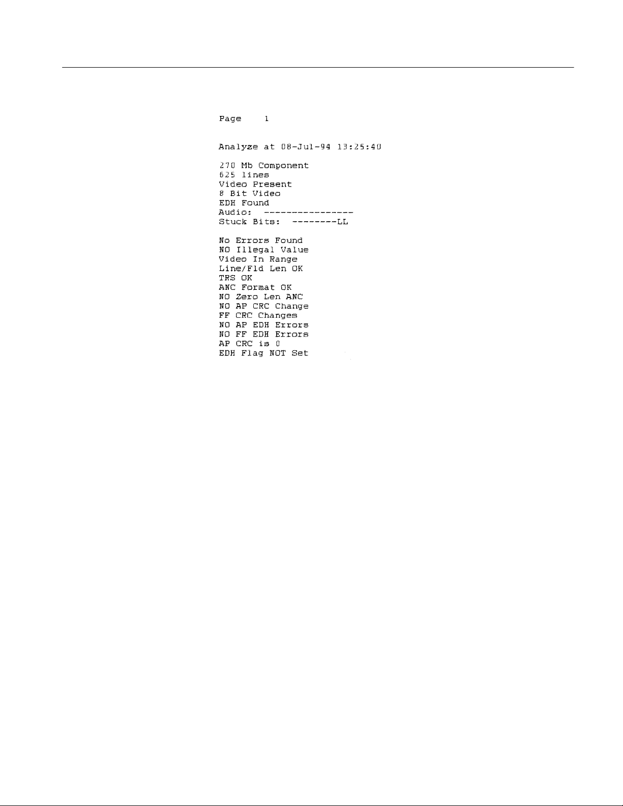
Testing the Connection and Settings. To test your printer connection and settings,
perform a signal analysis by pressing
Analyze. Then, press Shift-Analyze.The
printer should respond by printing an analysis report that resembles the one
shown in Figure 2--5.
2- 6 SDA 601 Serial Digital Analyzer
Page 29
Operating Information
Figure 2- 5: A Printed Analysis Report
SDA 601 Serial Digital Analyzer 2- 7
Page 30

Operating Information
Keypad and Display Conventions
Please see the Instruction card (Tektronix part number 070-8912-00) supplied
with your SDA601 for a “tour” of the keypad and an explanation of the display
symbols. For your convenience, the following panels are taken from the card.
Additional key functions are:
SLM (A) — Invokes the SLM display mode. Press this key to su-
percede any other display mode and display the Signal Level Meter on the SDA601 LCD. See page 2--21.
Cursor (B) — Invokes the Cursor data display mode. Press this
key to supercede any other display mode and display the cursor
position (line and sample) on the SDA601 LCD. See page 2--21.
Pulse Cross (E) — Press repeatedly to cycle through the four AUX
output pulse cross modes: Normal, H (horizontal), V (vertical),
and Both (horizontal and vertical). See page 2--24.
2- 8 SDA 601 Serial Digital Analyzer
Page 31

The On-Screen Display (OSD)
The OSD is a 12 line, 24 column display that can contain results from SDA601
Analyze and Watch sessions. It can be superimposed on the AUX output and
viewed on an attached video monitor. Toggle the OSD On/Off with the
On/Off key. The default OSD will resemble Figure 2--6 when the instrument is in
Watch mode. You can control several OSD characteristics (size, color, screen
position) through the Utility/OSD Setups submenu; see the User manual for
details.
Operating Information
Time (F) — Invokes the Time display mode. Press this key to su-
percede any other display mode and display the current date and
time on the SDA601 LCD. See page 2--23.
Review (G) — Invokes the Review display mode. Press this key to
supercede any other display mode and review the results of the
latest Analysis or Watch session on the SDA601 LCD. See page
2--23.
Insert
Figure 2- 6: The Default “Watching” OSD
The symbols on the bottom line of the OSD have the following meanings:
H The rotating line in the lower left indicates that Auto Power Off is enabled.
H The musical note symbol indicates that Alarms are toggled On with the
key or through the Alarm menu. This symbol can appear even when the
beeper and print errors items in the Alarm menu are set to Off.
H The “W” appears when the instrument is in Watch mode.
H The reversed “E” means that an error is detected.
SDA 601 Serial Digital Analyzer 2- 9
Alarm
Page 32

Operating Information
Preliminary Settings
H Similar reversed “S” and “SL” icons (not shown) will appear when SDA601
keypad is shifted and shift locked.
H The down-arrow in the lower right indicates that the B key may be used to
reveal another (higher-numbered) page. An up-arrow will appear in all other
pages to indicate that the
Y key may be used.
The Analyze OSD is similar; see Figure 2--10, on page 2--14.
Once the SDA601 is up and running, you should choose some settings
depending on how you’ll be using the instrument. These settings are made
through the Utility menu. Follow these directions to set the current date and
time, set the Battery Type, and enable Auto Power Down (if desired).
Set the Date and Time
1. To enter the SDA601 Utility menu, hold the Lock Out key down and press
the
ON button. Release the ON button, but continue to press the Lock Out key
until the display resembles Figure 2--7.
Figure 2- 7: The Initial SDA601 Utility Menu Display
2. Once in the Utility menu, use the
item, and press
Enter. The instrument display will change to resemble
Y and B keys to scroll to the Set Time
Figure 2--8.
Figure 2- 8: The Set Time Display
3. The underline cursor indicates the active character position. Move the cursor
with the
A and " keys. Enter the appropriate character from the SDA601
keypad. When the cursor is in positions that require numeric entry, the keys
will be automatically shifted. When you enter an appropriate character for
the field, the cursor will move one position to the right. The acceptable
2- 10 SDA 601 Serial Digital Analyzer
Page 33

Operating Information
month abbreviations are the first three characters of the English name: JAN;
FEB; MAR; APR; MAY; JUN; JUL; AUG; SEP; OCT; NOV; DEC.
Enter the time in 24 hour format; that is, if the present time is 4:15 pm, enter
16:15.
Set the Battery Type
4. When the correct date and time is shown on the display, press
Enter.Ifall
values are valid, the instrument will respond with the message “Time
Accepted.” If you have made an error and entered an invalid date or time, the
instrument will respond with an appropriate error message. If that happens,
correct the error and press enter.
5. Press any rectangular key to exit the Utility menu, or proceed to other
preliminary settings, as appropriate.
Confirm that the Battery Type setting is correct, and change it if necessary.
1. After setting the clock, press the
submenu item, and press
Enter.
B key once to scroll to the Diagnostics
2. In the Diagnostics submenu, scroll down to the Power Manage item with the
B key. Again, press Enter.
3. The top item in the Power Manage submenu is Battery Type. Toggle to the
selection that matches the type of battery you have installed in your
SDA601 by pressing either
A or ". The choices are “rechargeable” and
“disposable.” Select rechargeable when using NiCad AA cells or the optional
battery pack; choose disposable when you are using common Alkaline AA
batteries, which cannot be recharged. Press
Enter to confirm the choice.
4. When the correct battery type is indicated by an asterisk (*) on the lower
right of the LCD, continue to Auto Power Off, or press any rectangular key
to exit the Utility/Diagnostics/Power Manage submenu and return to normal
operation.
Enable (Disable) Auto
Power Off
“Auto Power Off” will switch the instrument off when ten minutes have passed
without a key press. Enable this feature when you are using battery power and
operating in an environment in which unplanned shutdown of the SDA601 is
permissible.
1. While still in the Utility/Diagnostics/Power Manage submenu, press the
key twice to scroll to the Auto Power Off item.
2. Disable/enable Auto Power Off by pressing either
A or ".PressEnter to
confirm the choice. Enabled Auto Power Down is indicated by a “rotating
line” symbol on the second line of the instrument display, and in the
lower-left corner of the OSD.
SDA 601 Serial Digital Analyzer 2- 11
B
Page 34

Operating Information
3. Use the
Disable (Enable) Timed LCD Backlight Turn Off
Another power saving feature of the SDA601 is timed turn-off of the LCD
backlight. It is enabled by default in a new or reset instrument. If you will always
operate with the AC adapter, you may wish to disable the feature. To toggle
backlight turn-off:
1. In the Utility/Diagnostics/Power Manage submenu, use the
2. Choose between “Timed Turn Off” and “On all the time” with either
3. As before, use the
Performance Verification
A performance verification procedure, which some users may require for
acceptance testing, is included in Section 3 of this manual.
Y and B keys to scroll to other “power manage” items, or press any
rectangular key to exit the menu and resume normal operation.
Y and B keys to
scroll to the LCD Backlight item.
A or ",
then press
Enter to confirm the choice.
Y and B keys to scroll to other “power manage” items, or
press any rectangular key to exit the menu and resume normal operation.
Using Your SDA601
NOTE. For more information on Serial Digital Video Systems, request Tektronix
publication 25W-7203-1 “A Guide to Digital Television System and Measurements” from your nearest Tektronix representative or field office.
See Figure 2--9 for a front and side view of the SDA601.
Here’s what you can do with your SDA601. Instructions for each function begin
on the indicated page.
H Analyze one second of the incoming signal and read the results on the
instrument display or an attached video monitor (page 2--13). You may also
print the results on an attached ASCII, serial printer (page 2--15).
H Watch the input signal, paying attention to selected signal characteristics, or
groups of characteristics (page 2--15). Errors are reported to the instrument
display panel and an attached video monitor. You may also log errors to an
attached printer (page 2--19).
H Set audible alarms to warn you of any errors encountered while the
instrument is “watching” the input signal (page 2--19).
2- 12 SDA 601 Serial Digital Analyzer
Page 35

Operating Information
H View decoded video on an analog picture monitor attached to the AUX
output (see page 2--4)
H Highlight, on the picture monitor, selected signal conditions or errors in the
context of the video signal. (page 2--24)
H Measure the approximate level of the digital input signal with the built-in
Signal Level Meter (SLM; page 2--21)
H Discover, with the help of video Cursors, the hex value of any sample in the
video frame (page 2--22).
H Shift the video frame horizontally and vertically with the Pulse Cross
feature to “see” the H and V intervals on the AUX picture monitor
(page 2--24).
Figure 2- 9: Fr ont and side views
Analyzing a Signal
SDA 601 Serial Digital Analyzer 2-13
Analyze Mode may be selected with the Analyze key at any time. In this mode,
the instrument attempts to lock onto the digital video signal and, if successful,
accumulates data from one second of the incoming signal. The instrument then
analyzes the status of the various signal characteristics and reports the results to
the Review List. The Review List may be viewed on the OSD (on an attached
Page 36

Operating Information
video monitor) as well as on the SDA601 LCD. The SDA601 up and down
arrow keys are used to scroll through the list of detected “conditions.”
The conditions detected and reported in an SDA601 analysis are:
Video format TRS (OK/incorrect)
Line standard (625 or 525) ANC Format (OK/incorrect)
Video present or missing Zero length ANC (yes/no)
Video resolution (8 or 10 bits) APCRC changes (yes/no)
EDH packet found/missing
FFCRC changes (yes/no)
Audio status (16 channels) APCRC errors (yes/no)
Stuck bits (if any) FFCRC errors (yes/no)
Illegal (digital word) values ØAPCRC (yes/no)
Video In/Out of range EDH flag set/not set
Line/field length (OK/incorrect)
Performing an Analysis. To analyze a signal, simply press
Analyze. The SDA601
will observe the incoming signal for one second, analyze the data, and write the
results to a “condition review list” and the OSD.
Reviewing the results on the OSD. There are three pages of results; use the
Y keys, as indicated by the arrow icons on the lower right of the OSD, to see all
B and
three pages.
Figure 2- 10: The Analyze OSD
Reviewing the results on the LCD. Use the B and Y keys to scroll through the
condition list on the instrument LCD. The display will “time out” after three
seconds of no key press and return to its pre-analysis state—Idle, or the data
enabled through the Display Select menu. Press Enter to return to the last-reviewed condition; press
B or Y to scroll down or up the list. You may also press
2- 14 SDA 601 Serial Digital Analyzer
Page 37

Operating Information
Review (G) to supercede all other LCD display modes and prevent “time out” of
the results display.
Printing an Analysis Report. With a printer connected to the RS-232 port and
properly configured (see the Reference section of the User manual), press
then
Analyze. A report, resembling the printout shown in Figure 2--5 (page 2--7),
Shift,
will be printed.
Audio and Stuck Bits Explained. Audio content and stuck bits are reported on the
LCD and Printer output in the same format as in the OSD, shown in Figure
2--10:
H The “Audio:” result line has room to display the status of all 16 audio
channels that can be embedded in digital video. The status of channels (#1
through #16, from left to right) are reported as “--” for no audio detected,
“A” for active audio, and “M” for mute (present, but silent).
H The “Stuck Bits:” line shows the status of the 10 bits of the video word (in
the active picture area), MSB to LSB left to right. If the signal contains any
stuck bits, they are indicated by an H (stuck high) or L (stuck low) in the
appropriate position. The two LSBs will be reported as L when an 8-bit
video signal is received. Other stuck bits may suggest either an incorrect
signal or faulty equipment.
Watching a Signal
Zero-length ANC. Is reported by the SDA601 when a Ø-value ANC “Data Count
word” is detected in the input data. The detection of zero-length ANC is
important because some digital video equipment can insert such an ANC into the
serial digital video data stream, even though it can cause difficulty in some
systems.
While Analyze takes a one-second “snapshot” of the input signal and reports the
status of a predefined list of characteristics, Watch mode permits continuous
observation of the signal characteristics—or “conditions”—of your choice. In
addition to reporting errors to the instrument display and the OSD, Watch mode
can also be configured to sound an audible (“beep” or “tick”) alarm to alert you
of any error, and log errors to a printer for later review.
The steps to monitoring a signal with the SDA601 are:
1. Select the conditions to be watched. This is done through the Watch menu,
which can be set—through the Utility menu—for selection of conditions on
a “Group” or “Item” basis. Group selection is the factory default.
In all, there are 20 Watch conditions. Eight conditions are always watched
and reported when “Watch Menu Type” is set to Group Select:
SDA 601 Serial Digital Analyzer 2-15
Page 38

Operating Information
Video format EDH packet found/missing
Line standard (625 or 525) Audio present/missing
Video present or missing Stuck bits (if any)
Bits in active picture (8 or 10) Other ANC (if any)
The twelve remaining conditions are organized into the four Watch groups:
Data Value Group: CRC Change Group:
Illegal (word) values
APCRC changes (yes/no)
Video In/Out of range FFCRC changes (yes/no)
Format Group: APCRC is/not Ø
Line/field length (OK/incorrect) EDH Group:
ANC Format (OK/incorrect) AP EDH errors (yes/no)
TRS (OK/incorrect) FF EDH errors (yes/no)
Zero length ANC (yes/no) EDH flag set/not set
When only the Data Value group is set to “Watch,” then, the SDA601 will
actually observe the status of ten conditions—the eight default conditions,
plus Illegal Values and Video In/Out of Range. If all four groups are selected,
all 20 conditions will be monitored.
Group selection can be inconvenient in some circumstances, however. An
example is observing a changing test signal that is being generated with
ØAPCRC. In this case, FFCRC changes are not an error, but a non-zero
APCRC is. Watching the CRC Change Group, then, could result in
inappropriate or misleading alarms.
To prevent this conflict, set the Watch Menu Type to “Item Select” through
the Utility menu and select the “AP CRC Not Ø” item through the Watch
Menu. To set the Watch Menu Type:
a. Hold the
menu. Release the
Lock Out key down and press the ON button to enter the Utility
ON button, but continue to press the Lock Out key until
the display resembles Figure 2--11.
Figure 2- 11: The Initial SDA601 Utility Menu Display
b. Go to the Watch Menu Type menu item by pressing the
B key three
times.
c. Press the
" key once to choose Item Select, then press ENTER to confirm
the choice.
d. Press
Watch to exit the Utility menu.
2- 16 SDA 601 Serial Digital Analyzer
Page 39

Operating Information
When Item Select is in effect, the list of “always-watched” conditions is
reduced to Video Format (270 Mb Component, for example) only. All other
items must be selected one-by-one through the Watch menu. The Watch
items, in the order they appear on the Watch menu, are:
Line Standard (report 525 or 625, or alarm on one or the other)
Video Missing
Active Picture Bits (8 or 10)
EDH Packet
Embedded Audio
Stuck Bits
Other ANC Data (not Audio or EDH)
Illegal Word Values
Over-range Video
Line/Field Length
TRS Errors
ANC Format Errors
Zero Length ANC
APCRC Changes
FFCRC Changes
APCRC not Ø (report, or alarm if not Ø)
AP EDH Errors
FF EDH Errors
EDH Flag Set
2. Set the appropriate alarms; see page 2--19.
3. Once all conditions have been selected and alarms configured, begin the
Watch session by pressing Watch. The message “Watch Started” will appear
briefly on the LCD. If none of the display options (Signal Level, Cursor
Data, or Current Time) have been turned on, the display will “time out” to
resemble Figure 2--12. If one or more of the LCD display modes (see page
2--20) has been activated, the display will revert to the display mode(s), and
the Watch session will continue in the background. In all cases, the results of
the session will be written to the OSD; press
Insert On/Off, if necessary.
Figure 2- 12: The SDA601 “Watching” Display
4. Review the condition list on the SDA601 LCD by pressing the
you reach the END OF LIST message. Use
Y to scroll back up the list as
B key until
desired. The LCD Watch review list will “time out” if more than 3.5 seconds
pass without a key press (press the
the display has timed out, press
Review key to prevent this time out). After
Enter to return to the last-displayed item;
SDA 601 Serial Digital Analyzer 2-17
Page 40

Operating Information
press
Y to move up the list and display the previous item; press B to display
the next item “down” the list.
5. If you have a video monitor connected to the AUX output, you may review
the condition list on the OSD. Toggle the OSD On with the
then page the OSD up and down with the
Y / B keys.
Insert On/Off key,
Pausing a Watch Session. A Watch session is temporarily suspended when you
invoke any other SDA601 menu (besides the Watch menu). Data collection
continues, but OSD and printer updates are suspended. When you exit the menu
by pressing a rectangular key, the OSD will update to include all events during
the time spent in the menu.
Stopping a Watch Session. The current Watch session will end when you press
Analyze or enter the Watch menu. After the analysis, or on leaving the Watch
menu, you may begin a new Watch session by pressing
Watch. Note that the
SDA601 will “forget” all data collected during a Watch session when the session
is concluded.
Restarting a Watch session. Pressing
Watch during a Watch session will restart the
Watch mode, resetting the elapsed time counter and the printer page count to
zero.
Figure 2- 13: Watch Errors Reported on the OSD
2- 18 SDA 601 Serial Digital Analyzer
Page 41

Operating Information
Interpreting Error Reports. The SDA601 reports errors in many Watch conditions
to the review list on an “errored seconds” basis, as shown in Figure 2--13. In this
illustration, one second of the Watched signal—approximately 25 seconds after
the Watch session was started—contained one or more changes in both the
FFCRC and the APCRC. In addition, more than 254 one-second periods of the
signal contained non-zero APCRCs (254 is the highest count possible in the
SDA601). The most-recent non-zero APCRC was detected in the last reported
one-second period, 7:12 into the Watch session.
The same reporting format is used on the SDA601 LCD.
Alarms
Alarms are enabled through the Alarm menu. When enabled, an alarm is
generated when one or more signal conditions or errors are detected by the
SDA601 in Watch mode. The SDA601 has two types of alarm:
H A “beeper” (audible) alarm that may be configured in one of three ways:
H Long Beep — Several seconds long, produced each time an alarm
condition is detected. In the case of frequently-recurring errors, the beep
will repeat continuously, if necessary; however, there may be fewer than
one alarm per error condition.
H Short Beep — One second duration; otherwise similar to the Long Beep.
H Beep “Tick” — A very short beep, almost a tick; useful when there are
many alarm conditions, when they occur in “bursts,” or for audible
feedback when performing equipment adjustments for proper operation.
H A Printer alarm, output on the RS-232 port. There are two ways to use the
printer during watch sessions:
H Log each error — or as many as the printer buffer allows. Intended for
extended monitoring of the signal when few, if any errors are expected.
You can leave the SDA601 (powered by the AC adapter) and a printer
unattended to log and help diagnose intermittent problems. This is the
same as the audible alarm in that, once configured, it can be controlled
with the
Alarm On/Off key.
H Print an error report every ten seconds — Strictly speaking, this option is
not an alarm because when it is selected, the instrument will print a
report every ten seconds of the Watch session whether an error has been
detected or not, and regardless of the Alarm On/Off state (set with the
key or through the menu). The print line will contain at least the time
and video format; errors, if any, that have occurred in the preceding
ten-second interval will also be printed.
Select alarm conditions or errors through the Watch menu (see “Watch Mode,”
above). Conditions that will always trigger an alarm if detected by the SDA601
in Watch mode are:
SDA 601 Serial Digital Analyzer 2-19
Page 42

Operating Information
No PLL Lock
Video Missing
“Other” ANC Data
Illegal Value
Video Over Range
Line/Field Len
EAV/SAV/TRS Error
ANC Format Error
Zero Length ANC
AP CRC change
FF CRC change
AP EDH error
FF EDH error
Flag Set
Conditions that will trigger an alarm only if they are configured to do so through
the Item W atch menu are:
Line Std Detect (if “Alarm if 525” or “Alarm if 625” is selected)
AP Bits (8/10) (if “Alrm if 8 bits” or “Alrm if 10 bits” is selected)
EDH packet miss (if “Alarm if Miss” is selected)
AP CRC Not Ø (if “Alarm Not Ø” is selected)
LCD Display Modes
Configure the beeper and printer alarms through the Alarm Menu. As you might
expect:
1. Enter the Alarm menu (press
Shift, then Alarm On/Off).
2. Scroll to the desired menu item with the B / Y keys.
3. Select the option with the
4. Confirm the option choice by pressing
A / " keys.
Enter.
5. Exit the Alarm menu by pressing any rectangular key.
Once the alarms are configured through the Alarm Menu, you may toggle all
alarms On/Off with the
Alarm On/Off key (which duplicates and overrides the
function of the “Alarm On/Off” item in the Alarm Menu). Note that turning the
alarms “On” with this key (or menu item) is equivalent to “arming” the alarms:
regardless of all other configuration options, the alarms will not “sound” unless
they are also turned On through the “Alarm On/Off” menu item or with the
key.
On/Off
Alarm
Three SDA601 LCD display modes—SLM (Signal Level Meter), Cursor, and
Time—may be invoked directly with the corresponding key (see Figure 2--14), or
through the
supercedes all other uses of the display. When selected through the
Display Select key/menu. When the mode is selected with its key, it
Display Select
menu, a mode will “time share” the display with any previously active mode(s).
2- 20 SDA 601 Serial Digital Analyzer
Page 43

Operating Information
A fourth display mode, Review, may be invoked with the
Review key only. The
four display modes are explained in the next few paragraphs.
Figure 2- 14: The Display Mode Selection Keys
SLM Display Mode. The SDA601 displays the relative level of the serial digital
input signal when you press the
through the
Display Select key/menu. The display will resemble Figure 2--15; note
SLM (A) key, or toggle “Disp Sig Level” On
that a longer “bar” indicates a weaker signal (often due to a longer cable).The
SDA601 SLM can help you identify points in your system where the digital
video signal may be marginal because of long cable runs or faulty equipment.
The signal level display will report an 800 mV
input signal as approximately
p-p
Ø dB (usually, only one segment will be “lighted,” if any).
Figure 2- 15: The SDA601 Signal Level Display
Selecting the Cursor, Time, or Review operating modes with the respective
keys—(
Signal Level display by pressing the front panel
Cursor (B), Time (F),orReview (G)—will turn the SLM Off. Reselect the
SLM (A) key, or—if you want two
or more modes to alternate on the display—toggle the SLM On through the
Display Select key/menu.
Cursor Display Mode. The SDA601 Cursor mode, selected by pressing the Cursor
(B)
key, makes it possible to locate a single word in the digital video frame and
discover the actual (hexadecimal) value of the selected word and the three words
SDA 601 Serial Digital Analyzer 2-21
Page 44

Operating Information
that follow. See Figure 2--16. The location of the selected word in the video
frame is also indicated by “cross hair” cursors in the AUX output; connect an
analog video monitor to see the cross hairs.
Figure 2- 16: The Cursor Data Display
The first line of the cursor data display contains the hexadecimal values of the
selected word and the three that follow it. Values typical for the SAV timing and
reference signal are shown in Figure 2--16. The video “type” of the selected word
is indicated by the sample ID:
B=C
color difference
B
Y = Cosited luminance
R=C
color difference
R
y (lowercase) = Isolated luminance
The second line contains the coordinates of the selected word. In the example,
the selected word is number 1712 of line 4 in field 1.
The cursor movement icon will be visible on the second line when the arrow
keys are “active” for cursor positioning. Normal cursor movement is one line up
or down for each
Engage shift lock (pressing
Y or B key press, and one word per press of the A or " key.
Shift twice) to accelerate horizontal movement to 20
words per key press, and increase vertical movement to 10 lines per key press.
Press Shift again to return to “fine” cursor control.
The cursor cross hairs are inserted in the AUX output whenever the
Cursor key is
pressed; they are not removed when Cursor mode is deactivated. You may
remove the cross hairs from the video display by setting Video Cursor, in the I/O
menu, to “No Display.”
The Cursor Data display may also be invoked through the Display Select menu, but
Cursor cross hairs must then be enabled separately, through the
To exit the Cursor Data display mode, press the
SLM (A), Time (F),orReview (G)
I/O menu.
key, or turn the display Off through the Display Select menu.
2- 22 SDA 601 Serial Digital Analyzer
Page 45

Operating Information
NOTE. To remove the cross hairs from AUX output—regardless of how you exit
Cursor Data display mode—you must also set the Video Cursor item in the
I/O
menu to “No Display.”
Figure 2- 17: The SDA601 Time Display
Time Display Mode. Press the Time (F) key to devote the SDA601 display to the
current date and time. If you wish to alternate the time display with previouslyselected SLM or Cursor data, toggle the “Disp Cur Time” item On through the
Display Select menu. The LCD will resemble Figure 2--17.
AUX Output Modes
Review Display Mode. Press the
Review (G) key to cancel the other display modes
(SLM, Cursor, and Time) and review the results of the ongoing Watch session—or the most recent Analysis—on the LCD. Once you have pressed
(G), the SDA601 display will resemble one of the two shown in Figure 2--18; use
the
B key to review the status of individual Analyze or Watch items.
Review
OR
Figure 2- 18: The First Review Display
Recall that the AUX output signal is “pseudo-video” that is decoded from the
digital input signal. It may be viewed on an analog video monitor. The AUX
output has three optional modes: the OSD (on-screen display), Pulse Cross, and
SDA 601 Serial Digital Analyzer 2-23
Page 46

Operating Information
Highlighting. See page 2--9 for an explanation of the OSD; Pulse Cross and
Highlighting are discussed in the following paragraphs.
Pulse Cross. Pulse Cross is an SDA601 AUX output mode that allows the user
to “see” the horizontal and/or vertical intervals, which are normally blanked in
video monitors. The original four-word timing reference signals (TRS, which
contain EAV and SAV) are replaced with legal video samples, and analog H and
V sync information is inserted in the original active picture region. There are
four pulse cross “states”:
Normal — blanked intervals, the instrument default
HCross — reveals the “horizontal interval” region of the signal
VCross — reveals the “vertical interval” region of the signal
Both — combines HCross and VCross
To select among the four pulse cross states, press the
Pulse Cross (E) key repeated-
ly until the desired state is visible on the video monitor.
To invoke pulse cross through the I/O menu:
1. Enter the I/O menu (press
2. Press the
3. With the
B key repeatedly to scroll down to the Pulse Cross menu item.
A / " keys, scroll to the desired pulse cross option.
Shift, then Insert On/Off).
4. Press Enter to select the new option.
5. Press any rectangular key to exit the I/O menu.
Highlighting. When the Highlighting option is selected, the SDA601 “flashes”
pixels in the AUX “video” output that correspond to certain Watch conditions.
With highlighting, you can visually monitor the occurrence, placement, and
prevalence of these signal conditions in the context of the video signal.
The following Watch conditions or errors can be highlighted on an attached
video monitor:
H ANC packet format error (e.g., checksum or parity errors)
H Zero-length ANC packets
H Other ANC data (data that is neither audio nor EDH format)
H Incorrect line/field length
H Incorrect TRS/EA V/SAV format
H Illegal data values
H Out of range video levels
2- 24 SDA 601 Serial Digital Analyzer
Page 47

Operating Information
To use Highlighting:
1. Configure the SDA601 to monitor one or more of the above items; see
“Watching a Signal” beginning on page 14.
Saving and Recalling
Presets
2. Enter the I/O menu (press
Shift, then Insert On/Off).
3. The first I/O menu item is Highlighting. Use the A or " key to select “On,
Dim Video” then press
Enter to confirm the choice.
Dim Video reduces the video signal by 50%, ensuring good contrast between
the video signal and highlighted pixels.
4. Exit the I/O menu by pressing any rectangular key.
5. If necessary, start or restart the Watch session by pressing
Watch.
6. The default OSD will obscure any highlighting in the portion of the picture
that it occupies. Therefore, if the OSD is on, toggle it off with the
Insert On/Off
key.
A convenient way to see the effects of Highlighting is to set either the Data
Value Group or the Video Over Range item to Watch, then input a Pluge signal.
The “sub-black” portion of active video will be highlighted.
Note that the ANC highlight conditions occur in the horizontal or vertical
interval. Use Pulse Cross to “see” those conditions.
The configuration of the SDA601 at any given time may be saved as a Preset for
later recall. Three different instrument configurations can be saved. Using
presets, you can easily change between completely different combinations of (for
instance) Watch conditions, alarm settings, LCD display options, and AUX
output options. To save a Preset:
1. Enter the Presets menu (press
2. Press
B once to reach the Save Preset item.
3. Choose a preset storage location (1, 2, or 3) with the
Shift, then Display Select).
A / " keys. Remember
that previous contents of the storage location will be overwritten in the next
step.
4. Press
Enter to save the current settings in the indicated location. “Working...
Done” will appear on the LCD during the save process.
5. Press any rectangular key to exit the Presets menu.
SDA 601 Serial Digital Analyzer 2-25
Page 48

Operating Information
To recall a previously saved Preset:
1. Enter the Presets menu.
Software Reset
2. Choose the Preset (1, 2, or 3) with the
A / " keys.
3. Press Enter to recall the saved configuration. “Working... Done” will appear
on the LCD. Some settings (I/O and Display settings, for example) will
change instantly; Watch and Alarm settings will be restored in the next
Watch session.
4. Press any rectangular key to exit the Presets menu.
NOTE. Recalling a preset will turn Watch mode off.
To reset the instrument NVRAM and restore the SDA601 to “factory” default
settings, select the Factory Reset item in the Utility/Diagnostics/NVRAM/TIC
Dgs submenu. See page 3--6 for instructions.
CAUTION. All user settings and presets will be lost.
2- 26 SDA 601 Serial Digital Analyzer
Page 49

Performance Verification
Page 50

Page 51

Performance Verification Procedures
The specifications for this instrument can be verified using the following
step-by-step procedure. Equipment that is called out in this procedure is assumed
to be operating correctly and within calibration.
Perform these verification procedures at regular intervals to ensure that instrument performance is within tolerance. The recommended frequency of performance verification is once every 2000 hours (approximately 12 months) of
operation.
A performance verification checklist begins on page 3--3.
Step-by-step performance verification procedures begin on page 3--4.
Required Test Equipment
The following list of equipment represents the minimum required for the
Performance Verification procedures. Alternate equipment must meet the
minimum specifications for the listed equipment. Use of inadequate equipment
may result in faulty measurements or calibration.
Table 3- 1: Required Test Equipment
Item Qty Information/Requirements Example
AC Adapter 1 Std. SDA601 accessory
Cable Simulator Able to simulate 25 and 150
meters of Belden 8281 coaxial cable.
Video Measurement Set 1 Monochrome Picture M onitor
Capability;
6.25% (or better) waveform
amplitude measurement accuracy.
75 Ω Coaxial Cables 3 Belden 8281 coax;
Male/Male BNC ends
75 Ω BNC Termination 1 0.025% precision Tektronix 011-0102-01
Faraday Cable Clone
Tektronix 1780R or
1781R
Tektronix 012-0159-00
SDA 601 Serial Digital Analyzer 3- 1
Page 52

Performance Verification Procedures
Table 3- 1: Required Test Equipment (Cont.)
Item ExampleInformation/RequirementsQty
Serial Digital Television
Signal Generator
1 Generates (per CCIR 601):
Equalizer SDI Checkfield
100% Color Bars
Limit Ramp
60% Sweep;
Erroneous FF CRC
Erroneous AP CRC
Zero-value (Ø) AP CRC
Tektronix
TSG 601 or TSG 422
Spectrum Analyzer 1 Freq. Range: 325 MHz
Sensitivity: up to 50 dB
Internal tracking generator
N-to-BNC adapter 2 Male N to female BNC Standard Tektronix 2712
High Frequency RF Bridge 1 ≥46 dB return loss sensitiv-
ity, 50 kHz to 325 MHz
75 Ω BNC adapter 1 Male-to-male Hewlett-Packard
Precision 50 Ω BNC cable 2 Tektronix
Tektronix 2712 Option 04
accessory; Tektronix
part number 103-0045-00
Wideband Engineering
part number A57TGACR
part number 1250-1288
part number 012-0482-00
3- 2 SDA 601 Serial Digital Analyzer
Page 53

Performance Verification Checklist
Use the following checklist if you are familiar with the operation of the SDA601
as well as digital video performance verification techniques. Step-by-step
instructions for all of the procedures begin on page 3--4.
1. Beeper and LCD display
2. OSD (on-screen display)
3. Keypad Test
4. AP CRC present, not 0
5. Erroneous FF CRC
6. Erroneous AP CRC
7. Ø AP CRC
8. Cursor and Data V alues
Performance Verification Procedures
9. Signal Level Meter Accuracy/Resolution
10. Current Time
11. Highlighting
12. Pulse Cross
13. Pixmon Y (white amplitude, sync amplitude, DC offset)
14. Pixmon R–Y Peak Amplitude
15. Pixmon B–Y Peak Amplitude
16. Serial Receiver Equalization
17. Print Report
18. Return Loss
SDA 601 Serial Digital Analyzer 3- 3
Page 54

Performance Verification Procedures
Performance Verification Procedures
Use the following step-by-step procedures to verify that the SDA601 meets
published specifications (see Section 1 of this manual). The order of these
procedures has been chosen to minimize changes in equipment setup. Performance parameters may be checked in any order.
Preparation
1. Connect the equipment as shown in Figure 3--1. Be sure all cable simulator
switches are in the “OUT” position.
Figure 3- 1: An Equipment Setup for Performance Verification
3- 4 SDA 601 Serial Digital Analyzer
Page 55

Performance Verification Procedures
2. Switch the equipment on and allow a 20-minute warm-up. Set the front panel
controls of the Tektronix 1780 (or 1781) as listed in Table 3--2.
Table 3- 2: Initial Settings for the Video Measurement Set
Control Setting
LEFT DISPLAY PIX
RIGHT DISPLAY WFM
INPUT CH A
REF INT
FILTER FLAT
WFM HORIZONTAL TWO, LINE
GAIN NORMAL
MAGNIFIER OFF
The picture on the Left Display of the Video Measurement Set should
resemble Figure 3--2. If the center portion of the display does not contain the
darker OSD (on-screen display) rectangle, press the SDA601
Insert On/OFF
button to toggle the OSD On.
Figure 3- 2: AUX Output Containing the On-Screen Display (OSD)
3. To enter the SDA601 Utility menu, hold the
the
ON button. Release the ON button, but continue to press the Lock Out key
Lock Out key down and press
until the display resembles Figure 3--3.
SDA 601 Serial Digital Analyzer 3- 5
Page 56

Performance Verification Procedures
Figure 3- 3: The Initial SDA601 Utility Menu Display
4. Reset the SDA601 software through the Utility:Diagnostics:NVRAM/TIC
Dgs:Factory Reset menu item. To do so:
Procedures
H Press
Y once to reach the “Diagnostics..” menu item, then press Enter to
“drop into” the Diagnostics submenu.
H Press
H Press
B three times to reach the “NVRAM/TIC Dgs..” menu item, then
press
Enter to “drop into” the NVRAM/TIC Dgs submenu.
Y twice to reach the “Factory Reset” menu item, then press Enter.
Miscellaneous Functions
1. Beeper and LCD display
a. Enter the SDA601 Utility/Diagnostics/Device Tests submenu with the
following steps:
H Press the
Y button once, then press ENTER to “drop into” the
Diagnostics submenu.
H Press the
B button twice, then press ENTER to access the Device
Tests submenu. The first submenu item is “Test Beeper.”
b. Press
c. Press the
ENTER to verify the function of the audible alarm “beeper.”
B button once to access the “LCD Pattern” menu item, then
press
ENTER to verify the function of all LCD pixels. All character
blocks will cycle on, then off.
d. Press the
B button once to end the LCD test and enter the next device
test, “Clear OSD.”
2. OSD (on-screen display)
a. Continuing from procedure 1,pressthe
B button once again to reach the
“Fill OSD Screen” menu item.
b. Press
ENTER. Check the Left Display of the Video Measurement Set to
verify that the OSD rectangle is filled with display characters.
3- 6 SDA 601 Serial Digital Analyzer
Page 57

3. Keypad Test
Performance Verification Procedures
a. Continuing from the previous procedure, press the
ENTER to access the “Keypad Test” menu item.
b. Press every SDA601 key and button (except
B button, then press
ENTER and On) one at a
time. Verify that the name of each key/button is written to the second
LCD line when the key or button is pressed.
c. After you have verified the operation of the keypad, press
Watch to exit
the Utility menu.
Analyze Functions.
4. APCRC present, not 0
a. On the TSG601, press
M to select the Equalizer SDI signal.
b. If the TSG601 LCD indicates “CRC=off,” press CRC On/Off to toggle the
CRC On.
c. Enter the TSG601 CRC menu by pressing
Shift, then CRC On/Off.
d. The TSG601 display should indicate that both the Full-Field (FF) and
Active-Picture (AP) CRCs are set to “NORM,” as shown in Figure 3--4.
If either CRC is not set to NORM, use the
A and " keys to select
between FFCRC and APCRC and the up/down keys to change the
status. Press
ENTER to confirm the changes. When you are done, the
display should resemble Figure 3--4.
Figure 3- 4: The TSG601 Display Indicating Normal CRCs
e. Press the SDA601
Analyze button. The left measurement display will
change to resemble Figure 3--5; this is the first “page” of the OSD
analysis report.
SDA 601 Serial Digital Analyzer 3- 7
Page 58

Performance Verification Procedures
Figure 3- 5: The Analyze OSD
f. Press
B on the SDA601 to view the second page of the analysis report.
Verify that this page contains the following lines:
No Illegal Value
Video in Range
Line/Fld Len OK
TRS OK
ANC Format OK
NO Zero Len ANC
g. Press B on the SDA601 to view the third page of the analysis report.
Verify that this page contains the following lines:
NO AP CRC Change
NO FF CRC Change
NO AP EDH Errors
NO FF EDH Errors
AP CRC NOT Ø
EDH Flag NOT Set
5. Erroneous FF CRC
a. Continuing from procedure 4, use the TSG601 arrow keys to change the
FFCRC status to ERR (error), and press
Enter to confirm the status. The
display will resemble Figure 3--6.
3- 8 SDA 601 Serial Digital Analyzer
Page 59

Performance Verification Procedures
Figure 3- 6: The TSG601 Display Indicating an Erroneous FFCRC
b. Press the SDA601
Analyze button. The instrument will analyze the
incoming signal and, in a few seconds, return to the first page of the
analysis report.
c. Verify that page 1 of the analysis report contains the line:
Errors Found
d. Press the SDA601
B button twice to view the third page of the analysis
report on the video measurement set. Verify that this page contains the
line:
NO AP EDH Errors
FF EDH Errors Error
6. Erroneous AP CRC
a. Continuing from procedure 5, use the TSG601 arrow keys to change the
FFCRC status back to normal, and the APCRC status to ERRO (error).
The display should resemble Figure 3--7. Press
Enter to confirm the
status.
Figure 3- 7: The TSG601 Display Indicating an Erroneous APCRC
b. Press the SDA601
Analyze button. The instrument will analyze the
incoming signal and, in a few seconds, return to the first page of the
analysis report.
c. Verify that page 1 of the analysis report contains the line:
Errors Found
d. Press the SDA601
B button twice to view the third page of the analysis
report on the video measurement set. Verify that this page contains the
lines:
SDA 601 Serial Digital Analyzer 3- 9
Page 60

Performance Verification Procedures
7. Ø AP CRC
Figure 3- 8: The TSG601 Display Indicating a Zero APCRC
AP EDH Errors Error
NO FF EDH Error
AP CRC NOT Ø
a. Continuing from procedure 6, use the TSG601 arrow keys to change the
APCRC status to ZERO (Ø). The display should resemble Figure 3--8.
Press Enter to confirm the status.
b. Press the SDA601
Analyze button. The instrument will analyze the
incoming signal and, in a few seconds, return the OSD to the first page
of the analysis report.
c. Verify that page 1 of the analysis report contains the line:
Warnings Found
d. Press the SDA601
B button twice to view the third page of the analysis
report on the video measurement set. Verify that this page contains the
lines:
NO AP EDH Errors
NO FF EDH Errors
AP CRC is Ø
Display Options
8. Cursor and Data Values
a. Confirm that the TSG601 signal still contains NORMal FFCRC and Ø
APCRC. The generator CRC Menu display should still resemble Figure
3--8. Press the TSG Test Signals key to exit the CRC menu, then press B
to output the 100% Color Bars signal.
b. Press the SDA601
Cursor (B) key to invoke the Cursor Display mode.
The SDA display should resemble Figure 3--9.
3- 10 SDA 601 Serial Digital Analyzer
Page 61

Performance Verification Procedures
Figure 3- 9: The SDA601 Cursor Display
c. Move the Cursor vertically to the indicated line.
H For 525 line signals, press the SDA601
Y key once. Verify that the
second line of the LCD reads “F2 W 175 L262”
H For 625 line signals, press the SDA601
B key four times. Verify
that the second line of the LCD reads “F2 W 175 L 5”
d. Press the SDA
Shift key twice to enter “shift-lock” mode. Shift-lock
mode “accelerates” cursor movement.
e. Press
A repeatedly until the second line of the LCD reads:
H For 525 line signals, “F2 W1435 L262”
H For 625 line signals, “F1 W1707 L 5”
f. Verify that the sample values on the top line of the LCD are:
H For 525 line signals, “Y2AØ 2ØØ ØC4 ØE4”
H For 625 line signals, “y2ØØ 2ØØ 18Ø 1C8” (note lowercase “y”)
g. While watching the left “PIX” display of the video measurement set,
press and hold the SDA601
is visible and moving towards the top of the picture. Release the
h. Continue to watch the PIX display and press and hold the SDA
Y key; verify that the horizontal cross hair
Y key.
A key;
verity that the vertical cross hair is visible and moves from right to left
in the picture. (Note that you may have to hold the key down a few
seconds before the cross hair becomes visible on the right edge of a
625-line picture.) Release the
A key.
i. Press Shift to exit the SDA601 shift-lock mode.
9. Signal Level Meter Accuracy/Resolution
a. On the TSG601, press
M to select the Equalizer SDI signal.
b. Confirm that all switches on the cable simulator (or attenuator) are in the
OUT position.
c. On the SDA601, press
A (SLM) to display the signal level meter. Verify
that 0, 1, or 2 meter segments are “on,” and note the number.
SDA 601 Serial Digital Analyzer 3- 11
Page 62

Performance Verification Procedures
10. Current Time
d. Set the cable simulator to 25 meters (if you are using a variable
attenuator, set it to 2.5 dB).
e. Verify that 1 or 2 more meter segments are “on” than in step c.
a. Press the SDA601
Time (F) key.
b. Verify that the current date and time are correct.
I/O Menu.
11. Highlighting
a. On the TSG601, press
F to select the “Limit Ramp” signal. Confirm that
the limit ramp signal is visible on the left display of the video measurement set.
b. Enter the SDA601 Watch menu (press
resemble Figure 3--10.
Figure 3- 10: The First Watch Menu Display
c. Press the SDA601
Enter to confirm the change.
Press
" key once to toggle the second line to “Watch.”
Shift, then Watch). The LCD will
d. Press
Watch.
e. If the OSD is present on the left display of the video measurement set,
Insert On/Off (on the SDA601) to toggle the OSD off.
press
f. Enter the SDA601 I/O menu (press
Shift, then Insert On/Off). The LCD
will resemble Figure 3--11.
Figure 3- 11: The I/O Menu/Highlighting Item Display
3- 12 SDA 601 Serial Digital Analyzer
Page 63

Performance Verification Procedures
g. Press the SDA601
“On.” Press
" key once to change the second display line to
Enter to confirm the change.
h. Verify that the “sub-black” region of the picture alternates (“flashes”)
between the original luminance level and white.
i. Press the SDA601
Video.” Press
" key once to change the second line to “On, Dim
Enter to confirm the change.
j. Verify a reduction (approximately 50%) in the picture brightness. Verify
that the sub-black region of the picture continues to flash, and that the
“over-white” region of the ramp alternates beween its new (50% gray)
level and white.
k. Press the SDA601
“Off.” Press
" key once more to change the second display line to
Enter to remove Highlighting from the picture.
12. Pulse Cross
a. Continuing from the previous procedure, press the SDA
B key once to
reach the Video Cursor item of the I/O menu. If this item is set to
“Display,” press
andthenpress
" to change the second display line to “No Display,”
Enter to confirm the change.
b. Press any rectangular SDA601 key to exit the I/O menu.
c. On the TSG601, press
J to select the “60% Sweep” signal. Confirm that
the sweep signal is visible on the left “PIX” display of the video
measurement set.
d. Press the SDA601
Pulse Cross key once; verify that the “horizontal
blanking” region is visible (as a dark vertical band) on the left measurement set display.
e. Press the SDA601
Pulse Cross key once again; verify that the “vertical
blanking” region is visible (as a dark horizontal band) on the measurement set display.
f. Press the
Pulse Cross key a third time; verify that both vertical and
horizontal blanking regions are visible on the left measurement set
display.
g. Press the
Pulse Cross key one last time to return the picture to normal.
AUX Output.
13. Pixmon Y (sync amplitude, peak amplitude, DC offset)
Specifications: 300 ± 75 mV; 700 ± 175 mV; ≤ 500 mV
a. On the TSG601, press
B to select the 100% Bars signal. Confirm that
the 100% Bars signal is visible on the measurement set PIX display.
SDA 601 Serial Digital Analyzer 3-13
Page 64

Performance Verification Procedures
b. Enter the SDA601 I/O menu by pressing
c. Press the SDA
Y key once to reach the AUX menu item. Confirm that
Shift, then Insert On/Off.
the current setting (on the second LCD line) is “Pixmon Y.”
d. Select the voltage cursors on the right measurement set waveform
display. Use the cursors to verify that the Sync amplitude of the
SDA601 output is between 225 mV and 375 mV.
e. Use the measurement set voltage cursors to verify that the peak Y
amplitude of the SDA601 output is between 525 and 875 mV (700 ±
175 mV) above blanking level.
f. Through the measurement set CONFIGURE touch-display, set the input
coupling to GND and adjust the trace to a convenient ground reference.
g. Change the measurement set coupling back to DC and verify that
blanking level is at 0 V ± 500 mV.
14. Pixmon R–Y Peak Amplitude
Specification: 700 ± 175 mV
a. Continuing from procedure 13,presstheSDA
" key once to change the
AUX output choice to “Pixmon R–Y.” Press Enter to confirm the choice.
b. Use the measurement set voltage cursors to verify that the peak R–Y
amplitude is between 525 and 875 mV above blanking level.
15. Pixmon B–Y Peak Amplitude
Specification: 700 ± 175 mV
a. Continuing from procedure 14,presstheSDA
" key once to change the
AUX output choice to “Pixmon B–Y.” Press Enter to confirm the choice.
b. Use the measurement set voltage cursors to verify that the peak B–Y
amplitude is between 525 and 875 mV above blanking level.
c. Press the SDA
" key once again to change the AUX output choice back
to “Pixmon Y.” Press Enter to confirm the choice.
Input Characteristics.
16. Serial Receiver Equalization
Specification: Proper operation with 800 mV launch amplitude and up to
15 dB loss at 135 MHz, using coaxial cable with
a. At the TSG601, press the
B key to select the 100% Color Bars signal.
Ꭹ loss characteristics.
1 f
b. Confirm that the Color Bars and the OSD are visible on the measure-
ment set PIX monitor. Toggle the OSD On, if necessary, by pressing
Insert On/OFF (on the SDA).
3- 14 SDA 601 Serial Digital Analyzer
Page 65
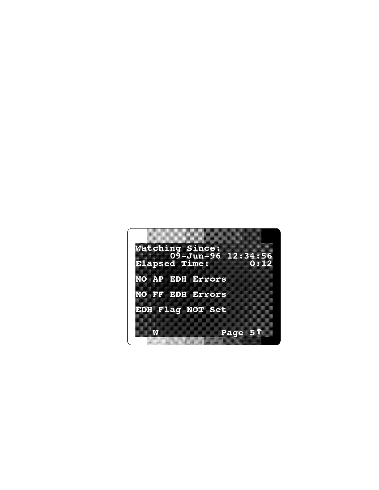
Performance Verification Procedures
c. Through the SDA601 Watch menu, set the EDH group to “Watch” and
all other groups to “Off.”
H Press Shift, then Watch to enter the Watch menu.
H Use the
Y and B keys to select the watch groups.
H Use the A and " keys to select the appropriate state (Off or Watch),
then press
Enter to confirm the selection.
H When all groups are set correctly, press any rectangular key to exit
the Watch menu.
d. Set the cable simulator to 150 meters (set an attenuator to 15 dB).
e. Verify that the PIX monitor video is still stable.
f. Press the SDA601
g. Press the SDA
Watch key to initiate Watch mode.
B key to change to OSD page five; it will resemble
Figure 3--12.
Figure 3- 12: Page Five of the Watching OSD
h. Allow the instrument to run for at least 2.5 minutes.
i. Check the OSD to Verify that no EDH errors have occurred.
SDA 601 Serial Digital Analyzer 3-15
Page 66

Performance Verification Procedures
RS-232 Port.
17. Print Report
a. Connect a cable wired as shown in Figure 3--13 between the SDA601
RS-232 connector and the DB25 COM2 port of a personal computer.
b. At the PC, run the Terminal accessory of MicrosoftR WindowsT,or
another communications application.
Figure 3- 13: SDA601-to-PC Cable Connections
c. Set the PC communications parameters:
H Baud = 9600
H Data Bits = 8
H Stop Bits = 1
H Parity = none
H Flow control = Software (Xon/Xoff)
H Connector = COM2
d. Set the following parameters in the SDA601 Utility:Printer Setup
submenu:
H Page Limit = 10
H Top of Form = Form Feed
H Lines per Page = 60
H EndofLine=CRandLF
H Flow Control = Software(XOFF)
3- 16 SDA 601 Serial Digital Analyzer
Page 67

Performance Verification Procedures
e. Set the following parameters in the SDA601 Utility:RS232 Setup
submenu:
H Baud Rate = 9600
H Set Parity = None
f. Press
Shift, then Analyze on the SDA601. V erify that the PC receives a
Analysis report similar to the one shown in Figure 2--5.
18. Return Loss
Specification: ≥ 15 dB from 1 MHz to 270 MHz, power On.
a. Connect a precision 50 Ω cable from the spectrum analyzer TG output to
the RF input of the RF bridge.
b. Connect a precision 50 Ω cable from the spectrum analyzer RF input to
the RF output of the RF bridge.
c. Connect a 75 Ω male-to-male BNC adapter to the RF bridge “device
under test” connector. The equipment setup should now resemble the
arrangement illustrated in Figure 3--14.
Figure 3- 14: Initial Return Loss Setup
SDA 601 Serial Digital Analyzer 3-17
Page 68

Performance Verification Procedures
d. Through the spectrum analyzer DEMOD/TG Menu, switch the tracking
generator ON and set the FIXED LEVEL to 0.00 dBm. Exit the
DEMOD/TG menu.
e. Set the spectrum analyzer:
H Span/div to 50 MHz;
H Vertical scale to 10 dB (per division);
H Frequency range to 300 MHz; and
H Resolution bandwidth to 300 kHz.
f. Turn the spectrum analyzer marker (MKR) ON and set it to 270 MHz.
g. Through the Input menu, set EXTERNAL ATTEN/AMPL to 0 dB.
h. Set the spectrum analyzer reference level to the first major division down
from the top on the analyzer display.
i. Note the reference level readout. This number will depend on the
characteristics of the RF Bridge and connecting cables.
j. Enter the Input Menu again and set the EXTERNAL ATTEN/AMPL
Amplitude to offset the reference level noted in the previous step. (For
example, if the Reference Level reading was –24.5 dBm, enter 24.5, then
press the – dBx key.)
k. Confirm that the reference level readout is now –0.00 dB.
l. Connect the RF Bridge Device Under Test connector (with the 75 Ω
Male-to-Male BNC adapter) to the SDA601 Serial Input. The BNC
adapter eliminates the need for a cable between the Bridge and the SDA,
and increases the accuracy of this measurement.
m. Confirm that the SDA601 is switched on, then Verify that the spectrum
analyzer reference level readout is ≥ 15dBm(thatis,atleast15dBm
down), and that the spectrum analyzer trace is below the reference level
at every frequency below the marker frequency.
3- 18 SDA 601 Serial Digital Analyzer
Page 69

Adjustment Procedures
Page 70

Page 71

Adjustment Procedures
This section consists of a detailed adjustment procedure that you may used to
return the instrument to in-spec operation. Equipment that is called out in this
procedure is assumed to be operating correctly and within calibration.
Adjust the Signal Level Meter once every 2000 hours or one year of operation.
Adjust the Deserializer VCO if the instrument fails to meet the Serial Receiver
Equalization specification during Performance Verification (see the previous
Section).
Perform these procedures in any convenient order. Note, however, that the
instrument must be “cold” (at room temperature, and switched Off for several
hours) when you begin the Signal Level Meter adjustment procedure.
Step-by-step adjustment procedures begin on page 4--2.
Required Test Equipment
The following list of equipment represents the minimum required for the
Performance Verification and Adjustment procedures. While alternate equipment
may be used, it is not recommended. Alternate equipment must meet the
minimum specifications for the listed equipment. Use of inadequate equipment
may result in faulty measurements or calibration.
Table 4- 1: Required Test Equipment
Item Qty Information/Requirements Example
AC adapter 1 Std. SDA601 accessory
Serial Digital Television
Signal Generator
Cable Simulator 1 Able to simulate 100, 200,
75 Ω Coaxial Cables 2 Belden 8281 coax;
SDA 601 Serial Digital Analyzer 4- 1
1 Generates (CCIR rec 601)
Equalizer SDI Checkfield
and 300 meters of Belden
8281 coax cable.
Male/Male BNC ends
Tektronix
TSG 601 or TSG 422
Faraday Cable Clone
Tektronix 012-0159-00
Page 72

Adjustment Procedures
Adjustment Procedures
Adjust SLM (Signal Level
Meter)
To ensure greatest accuracy of the SDA601 Signal Level meter over the entire
range of operating temperatures, perform this two-part procedure once every
twelve months. Please read completely through the following procedure before
attempting to adjust the SLM.
The first “pass” must be conducted on a “cold” instrument at room temperature
(approximately 20_ C=68_ F). For best results, leave the SDA601 switched
Off overnight and perform steps 4a through 4g immediately after switching the
instrument On. The second pass (step 6) must be conducted after the instrument
has operated (On, but not Watching) at an elevated ambient temperature
(approximately 50_ C = 122_ F) for at least one hour.
The instrument software saves and uses the “cal factors” from the two most
recent “Calibrate SLM” sequence; thus, for proper adjustment, both parts of this
procedure must be completed in order (cold, then hot).
1. Connect the equipment as shown in Figure 4--1.
Figure 4- 1: A Setup for SLM Adjustment
4- 2 SDA 601 Serial Digital Analyzer
Page 73

Adjustment Procedures
2. Press the TSG601
M key to select the EQULIZR SDI (Equalizer SDI
Checkfield) signal.
3. Switch the SDA601 On.
4. Perform the first, room temperature pass of the Calibrate SLM sequence.
a. Select the SDA601 Utility/Diagnostics/Calibration/Calibrate SLM
menu item with the following steps:
H Hold the
H Press the
Lock Out key down, and press the ON button.
Y key once, then press ENTER to access the Diagnostics
submenu.
H Press the
Y key four times, then press ENTER to access the Calibra-
tion submenu.
H Press
ENTER again to begin the SLM calibration sequence. The
display will resemble Figure 4--2 (note that the number on the
second line is unlikely to be 160).
Figure 4- 2: The First SLM Calibration Display
b. Verify that all switches on the cable simulator or attenuator are in the
OUT (0 meters) position, then press the SDA601
ENTER button.
c. The SDA601 LCD will be blank for a few seconds. Wait until the
message “Set to 100 meter” appears on the top line of the LCD. Set the
cable simulator to 100 meters (if using an attenuator, set it to 10 dB),
then press the SDA601 ENTER button.
d. Wait until the message “Set to 200 meter” appears on the LCD. Set the
cable simulator to 200 meters (or attenuate by 20 dB), then press the
SDA601
ENTER button.
e. Wait until the message “Set to 300 meter” appears on the LCD. Set the
cable simulator to 300 meters (set attenuator to 30 dB), then press the
SDA601
ENTER button.
f. Wait until the message “Press Enter to Save Cal Factors” appears on the
LCD. Press
ENTER to complete the sequence.
SDA 601 Serial Digital Analyzer 4- 3
Page 74

Adjustment Procedures
g. Wait until the “Calibrate SLM; Saving” message disappears from the
SDA601 display to ensure acceptance of the new Cal Factors.
5. Place the SDA601 in an elevated temperature (50_ C = 122_ F) environ-
ment for at least one hour. Power the instrument with an AC adapter and
leave it switched On, but do not provide an input signal.
NOTE. If no suitable oven is available for operating the SDA601 at an
elevated ambient temperature, you may substitute the following procedure
for step 5:
H Leave the instruments connected as shown in Figure 4--1; set all cable
simulator (or attenuator) switches to the OUT position.
Adjust the Deserializer
VCO (“Serial Pot”)
H At the TSG601, press the
set the ramp amplitude to 4 with the
G key to select the Shallow Ramp test signal;
A and " keys; and turn the Cb and
Cr output channels off through the “Channel Output Selection” item in
the Output Menu. (If using a Tektronix TSG 422 as the signal source,
simply set it to output the Digital Gray test signal.)
H Press the SDA601
Watch button to start (or restart) the Watch mode.
H Operate the TSG/SDA combination with these settings for at least two
hours, then proceed to the next step.
6. Repeat the Calibrate SLM sequence (steps 4a through 4g).
The Serial Pot settings influence the ability of the SDA601 to meet the Serial
Receiver Equalization specification.
1. Connect the equipment as shown in Figure 4--3.
2. Power up the TSG601 and SDA601. Allow a 20-minute warm-up.
3. At the TSG601, press the
M key to select the EQULIZR SDI (Equalizer SDI
Checkfield) signal.
4. Press the SDA601
Watch button to initiate the watch mode.
4- 4 SDA 601 Serial Digital Analyzer
Page 75

Adjustment Procedures
Figure 4- 3: A Setup for Adjusting the De-serializer VCO
5. Select the SDA601 Utility/Diagnostics/Calibration/Adj Serial Pot menu
item with the following steps:
H Hold the
Lock Out key down, and press the ON button.
H Press the Y key once, then press ENTER to access the Diagnostics
submenu.
H Press the
Y key four times, then press ENTER to access the Calibra-
tion submenu.
H Press the
B key. The SDA601 LCD should now resemble Fig-
ure 4--4 (the value of the adjustment will be between the minimum
of Ø and the maximum of 511; it is unlikely to be 321 as shown).
Figure 4- 4: The “Adj Serial Pot” Menu Item
SDA 601 Serial Digital Analyzer 4- 5
Page 76

Adjustment Procedures
6. Enter a value of zero by pressing the SDA601
0/Z key, and then ENTER.The
display will resemble Figure 4--5. The letter “E” may appear on the second
display line as shown, indicating VCO lock error. If the letter E is visible
(either constantly, or flashing on and off), continue with the next step; if the
“E” is not present, note that the lower permissible value is Ø and proceed to
step 8.
Figure 4- 5: The VCO Lock Error Indicator
7. Press and hold the
then press the
" key down until the “E” disappears from the display,
A key repeatedly until it returns. Adjust the setting until you
have discovered the lowest possible “no E” value. Note this value for later
use.
8. Enter a Serial Pot value of 511 by pressing
5/R–1/L–1/L,andthenENTER.As
in step 6 (above), the “E” may appear on the second display line to indicate
VCO lock error. If so, continue to the next step; if not, note that the higher
permissible value is 511 and proceed to step 10.
9. Press and hold the A key down until the “E” disappears from the display,
then press the
" key repeatedly until it returns. Adjust the setting until you
have discovered the highest possible “no E” value. Note this value.
10. Subtract the low “no E” value from the high value, multiply the remainder
by 0.6, and add the product to the low value. The result is the appropriate
“Serial Pot” value for this SDA601.
For example, if the lowest possible value discovered in step 7 was 45,
and the highest value—from step 9—was 492, the correct Serial Pot
value would be:
[
(
492 − 45)× 0.6]+ 45 = 313.2
11. Round your result (not the example!) from the previous step to the nearest
integer, and enter the value with the SDA601 numeric keys; press
ENTER
twice to confirm the new setting. When this step is complete, the display
should again resemble Figure 4--4, with the asterisk (*) at the end of the
second line.
4- 6 SDA 601 Serial Digital Analyzer
Page 77

Adjustment Procedures
Set the Date and Time
During normal instrument operation, press the
Time (F) key. If the date or time
displayed on the LCD is incorrect, follow these steps to reset the internal clock.
1. Enter the SDA601 Utility menu by holding
the
ON key.
2. Once in the Utility menu, use the
item, and press
Enter. The instrument display will change to resemble
Y and B keys to scroll to the Set Time
Lock Out down, while pressing
Figure 4--6.
Figure 4- 6: The “Set Time” Display
3. The underline cursor indicates the active character position. Move the cursor
with the
A and " keys. Enter the appropriate character from the SDA601
keypad. When the cursor is in positions that require numeric entry, the keys
will be automatically shifted. When you enter an appropriate character for
the field, the cursor will move one position to the right. The acceptable
month abbreviations are the first three characters of the English name: JAN;
FEB; MAR; APR; MAY; JUN; JUL; AUG; SEP; OCT; NOV; DEC.
Enter the time in 24 hour format; that is, if the present time is 4:15 pm,
enter 16:15.
4. When the correct date and time is shown on the display, press
Enter.Ifall
values are valid, the instrument will respond with the message “Time
Accepted.” If you have made an error and entered an invalid date or time, the
instrument will respond with an appropriate error message. If that happens,
correct the error and press enter.
5. Press any rectangular key to exit the Utility menu, or proceed to other
preliminary settings, as appropriate.
SDA 601 Serial Digital Analyzer 4- 7
Page 78

Adjustment Procedures
4- 8 SDA 601 Serial Digital Analyzer
Page 79

Maintenance
Page 80

Page 81

Maintenance
Battery Hints
Subsections are: Battery Hints; Preventive Maintenance; Troubleshooting Aids;
and Corrective Maintenance.
For optimal battery life and capacity, use the rechargeable NiCad b attery pack
(Tektronix p/n 119-4488-00) in full charge/discharge cycles. In other words, fully
discharge the battery pack before recharging, and then charge the battery pack
until fully charged, approximately 16 hours. A new battery pack will take a few
charge/discharge cycles to reach full capacity.
The Battery Type, Auto Power Down, and LCD Backlight functions in the
Utility/Diagnostic/Power Manage submenu also have an impact on battery life.
The battery types are disposable (Alkaline) or rechargeable (NiCad). The battery
type setting determines the voltage threshold for display of the “battery low”
message, and also controls the cut-off voltage for instrument operation. Be sure
this setting matches the type of battery installed in the SDA601. (See page 2--11)
The Auto Power Down function, when enabled, switches the SDA601 Off to
conserve battery life after approximately 10 minutes with no keypress. Auto
Power Down is indicated by a “rotating” line symbol that is visible (depending
on other display messages) in the middle of the second display line. (See
page 2--11.)
“Timed Turn Off” of the LCD Backlight is another charge-saving measure, and is
the factory default setting. When it is selected, the LCD backlight will be
extinguished after approximately three minutes of instrument inactivity. (See
page 2--12.)
Preventive Maintenance
Under average conditions, the SDA601 should have preventive maintenance
performed about every 2000 hours. This is approximately one year of operation.
Preventive maintenance includes cleaning, visual inspection, a performance
verification and, if necessary, adjustment. See Section 3 for performance
verification, and Section 4 for adjustment procedures.
Cleaning
SDA 601 Serial Digital Analyzer 5- 1
Clean the instrument often enough to prevent dust and dirt from accumulating in
or on it. Dirt can provide high-resistance electrical leakage paths between
conductors or components in a humid environment.
Page 82

Maintenance
CAUTION. The SDA601 case is made of molded plastic. Do not allow water to
get inside of any enclosed assembly or component. Do not clean any plastic
materials with organic cleaning solvents, such as benzene, tuolene, xylene,
acetone, or similar compounds, because they may damage the plastic.
Static-Sensitive
Components
The SDA601 contains electrical components that are susceptible to damage from
static discharge. Static voltages of 1 kV to 30 kV are common in unprotected
environments.
CAUTION. Static discharge can damage any semiconductor component in this
instrument.
Observe the following precautions to avoid static damage:
H Minimize handling of static-sensitive components.
H Transport and store static-sensitive components or assemblies in their
original containers, on a metal rail, or on conductive foam. Label any
package that contains static-sensitive assemblies or components.
H Discharge the static voltage from your body by wearing a wrist strap while
handling these components. Servicing static-sensitive assemblies or
components should only be performed at a static-free workstation by
qualified personnel.
H Nothing capable of generating or holding a static charge should be allowed
on the workstation surface.
H Keep the component leads shorted together whenever possible.
H Pick up components by the body, never by the leads.
H Do not slide the components over any surface.
H Avoid handling components in areas that have a floor or work surface
covering capable of generating a static charge.
H Use a soldering iron that is connected to earth ground.
H Use only special antistatic, suction-type or wick-type desoldering tools.
5- 2 SDA 601 Serial Digital Analyzer
Page 83

Troubleshooting Aids
Maintenance
The following is miscellaneous information about schematics, circuit board
illustrations, component numbering, and assembly numbering.
NOTE. No repair should be attempted during the warranty period.
Foldout Pages
Diagrams
Circuit Board Illustrations
The foldout pages at the back of the manual contain block and schematic
diagrams and circuit board illustrations.
The circuit number and electrical value of each component is shown on the
schematic diagrams. The first page in the Diagrams section (Section 7) explains
the schematic symbols and notations found on the diagrams. The Replaceable
Electrical Parts list gives a complete description of each component. Circuit
boards and assemblies are shown with a heavy border, for identification. If the
border does not completely encircle the schematic then that schematic only
portrays part of the circuitry on that board or assembly. The name and assembly
number of the circuit board are shown along the border as well as the serial
number range that the schematic represents.
NOTE. Check the Change Information section at the rear of the manual for
inserts describing corrections and modifications to the instrument and manual.
Electrical components, connectors, and test points are identified on circuit board
illustrations located on the inside fold of the corresponding circuit diagram or the
back of a preceding diagram.
Numbering
SDA 601 Serial Digital Analyzer 5- 3
The circuit board assemblies are assigned assembly numbers starting with A1.
Circuit boards have been assigned an assembly number so that they may be
ordered from Tektronix, Inc. The assembly numbers are as follows:
A1 Main Board Assembly
A2 Keypad Board Assembly
A3 LCD Board Assembly
A4 I/O Board Assembly
The part numbers for ordering these boards are listed first in the Replaceable
Electrical Parts list (EPL), in Section 6.
Page 84

Maintenance
The EPL is arranged in assembly-by-assembly order, as designated in ANSI
Standard Y32.16-1975. Each component is assigned a circuit number according
to its location within a circuit, which is shown in the parts list by combining the
assembly number and the circuit number.
EXAMPLE: R123 on assembly A2 would be listed in the EPL as A2R123.
Assembly listings in the EPL are followed by circuit board-mounted parts in
alphanumeric order. Chassis-mounted parts are listed at the end of the EPL.
NOTE. The complete part number shown in the parts list should be used when
ordering replacement parts.
Self-Diagnostics
Several self-diagnostic tools are built in to the instrument software. Most of
these tools may be found in the Utility/Diagnostics submenu.
The Diagnositics submenu is the last item in the Utility menu. Enter the Utility
menu when the instrument is in a normal operating mode—that is, not in a
menu—by holding
select the Diagnostics submenu by pressing the
Lock Out down while pressing ON. Once in the Utility menu,
Y key once; then ENTER to access
the Diagnostics choices, which are listed below. Some of the Diagnostic
submenu items are explained in other parts of this manual, or in the SDA601
User manual; the remaining submenu items are discussed after this listing.
(1) Show SW/FW Vers
Press Enter
(2) Power Manage ..
Press Enter
(a) Battery Type
Rechargeable <> Alkaline
LCD Backlight
(b)
TimedTurnOff<> On all the time
(c)
Auto Power Off
Disabled <> Enabled
Previous Menu
(d)
Press Enter
(3)
Device Tests ..
Press Enter
(a) Test Beeper
Press Enter
LCD Pattern
(b)
Press Enter
Clear OSD
(c)
Press Enter
(d)
Fill OSD Screen
Press Enter
Keypad Test
(e)
Press Enter
5- 4 SDA 601 Serial Digital Analyzer
Page 85

(f) RS232 loop back
Press Enter
Disp RS232 outs
(g)
Off <> On
Disp SLM Numeri
(h)
Off <> On
(i)
Previous Menu
Press Enter
(4)
NVRAM/TIC Dgs..
Press Enter
(a) Get TIC Serial
Press Enter
Get TIC Time
(b)
Press Enter
Read TIC Memory
(c)
<> 0
(d)
Factory Reset
1
Press Enter
Previous Menu
(e)
Press Enter
(5)
Flash Diags..
Press Enter
(a) Checksum Memory
Press Enter
Read Byte 10000
(b)
Press Enter
(c)
Writ Byte 10000
MIN = 0 <> MAX = 255
Erase Sec 10000
(d)
Press Enter
Read SLM Cals
(e)
Press Enter
(f)
Write Byte Loop
MIN = 0 <> MAX = 255
Previous Menu
(g)
Press Enter
(6)
Calibration..
Press Enter
(a) Calibrate SLM
Press Enter
(b)
AdjSerialPot
MIN = 0 <> MAX = 511
2
(c) Show Curr Temp
Press Enter
Set Manuf Wat ch
(d)
Press Enter
(e)
Previous Menu
Press Enter
(7)
FW Upgrade ..
Press Enter
1
This will reset the instrument to factory defaults; all current user settings will be overwritten.
2
This value is adjusted during manufacture. To be changed only by qualified service personnel; see page 4--4.
Maintenance
SDA 601 Serial Digital Analyzer 5- 5
Page 86

Maintenance
(a) Show Cur Bank
Press Enter
Download
(b)
Press Enter
Copy B1 to B∅
(c)
Press Enter
(d)
Previous Menu
Press Enter
(8)
Write Test Reg
tr: 0 <> 255
(9) Previous Menu
Press Enter
Submenu items explained.
1. Show SW/FW Vers — Press
ENTER to discover the Software Version (SWV)
and Gate Array Version (GAV) installed in your particular SDA601.
2. Power Manage .. see page 5--4
3. Device Tests ..
a. Test Beeper see page 3--6
b. LCD Pattern see page 3--6
c. Clear OSD self explanatory; used with the next item.
d. Fill OSD Screen see page 3--6
e. Keypad Test see page 3--7
f. RS232 loop back — This is a test of the SDA601 RS-232 hardware. To
perform this test, short conductors two and three (pins 2 and 3) of the
RS-232 connector, then press
ENTER. The first line of the LCD will
indicate “RS232 looping bk.” Watch the display for at least ten seconds;
the hardware is operating correctly if no error messages appear (to see
the error message, remove the short and watch the display for approximately five seconds).
g. Disp RS232 outs — This diagnostic was used during product develop-
ment and is not intended for servicing the instrument. When “On” is
selected, the number of unsent characters in the RS-232 buffer are
displayed—in some circumstances—on the LCD.
h. Disp SLM Numeri (Display SLM Numeric data) — This item was used
in developing the signal level meter (SLM) and the algorithm used to
calculate temperature-correction factors for the SLM. It may be helpful
in diagnosing problems with the SLM. When “On” is selected, a display
resembling Figure 5--1 will appear on the LCD during normal instrument
operation.
5- 6 SDA 601 Serial Digital Analyzer
Page 87

Maintenance
Figure 5- 1: Num eric SLM Data
The top line contains—in A/D units, or “LSBs”—the internal instrument
temperature, the corrected signal level, and the uncorrected (“raw”)
signal level. The second line contains a numeric readout of the corrected
signal strength in dB. This value corresponds to the LSBs reported in the
top line, and to the normal bar-graph display of the SLM.
To exit the numeric SLM display mode and replace the display with the
normal SLM bar graph, press the
SLM (A) key.
4. NVRAM/TIC Dgs.
The NVRAM/Timer (Touch MemoryT) microprocessor in the SDA601 is
contained in a button-shaped stainless steel can with its own lithium battery.
It is known widely as the “time in a can”—or “TIC.”
a. Get TIC Serial — Press
ENTER to discover the unique serial number of
the TIC. This is an easy way to verify the presence and function of the
TIC NVRAM.
b. Get TIC Time — Press
ENTER to read the number of seconds since 00:00
hours, January 1, 1970; the display will update each second and verify
the function of the TIC clock.
c. Read TIC Memory — Enter any TIC memory address (0–255) to read
the contents and verify that the instrument can retrieve data from TIC
NVRAM. To read the contents of memory location 159, for example,
press
1(L), 5(R),and9(X),thenpressENTER.
Figure 5- 2: The SDA Number Keys
SDA 601 Serial Digital Analyzer 5- 7
Page 88

Maintenance
d. Factory Reset see page 3--6
5. Flash Diags.
a. Checksum Memory — Press
ENTER to calculate a checksum of all 512
Kbytes of flash memory. The calculation will require approximately 7
seconds.
Typically, you will use the next three flash diagnostic items (b, c,andd)
together to confirm that the instrument can erase, read, and write to flash
memory. A useful approach is to:
H Read byte 1000 (b);
H erase sector 1, which begins at byte 10000 (d);
H read byte 10000 (b) to confirm the erase (the byte value should be FF);
H then write a new value into the byte (c); and finally
H read it back (b), to confirm the write.
b. Read Byte 10000 — Press
ENTER to read the content of byte 10000.
c. Write Byte 10000 — Enter a number from 0 to 255 with the number
keys (see Figure 5--2), then press
d. Erase Sec 10000 — Press
ENTER to erase sector 1, which begins with
ENTER.
byte 10000.
e. Read SLM Cals — Developed for use during design and manufacture;
not intended for use in the field.
f. Write Byte Loop — Developed for use during design and manufacture;
not intended for servicing the instrument. Pressing ENTER will put the
SDA601 into an infinite loop; switch the instrument Off to exit the loop.
6. Calibration.
a. Calibrate SLM see page 4--2
b. AdjSerialPot see page 4--4
c. Show Curr Temp — Press
ENTER to check the internal instrument
temperature in “A/D units,” not degrees F or C.
d. Set Manuf Watch — Developed for use during manufacture; not
intended for servicing the instrument. Pressing
ENTER will initiate
special, undocumented Watch-mode “conditions.”
5- 8 SDA 601 Serial Digital Analyzer
Page 89

Corrective Maintenance
Maintenance
7. FW Upgrade
CAUTION. DO NOT attempt to use any “FW Upgrade” items unless you are
carefully following instructions supplied with a Tektronix firmware upgrade kit.
Selecting item c without using the correct software and procedures can erase
portions of instrument memory and remove the ability to upgrade the firmware.
a. Show Cur Bank
b. Download
c. Copy B1 to B∅
8. Write Test Reg — This diagnostic was used during product development and
is not intended for servicing the instrument.
Obtaining Replacement
Parts
Torque Specification
Corrective maintenance deals with obtaining and replacing parts and assemblies
in the SDA601.
Replacement parts are available from or through the local Tektronix, Inc., field
office or representative.
When ordering parts be sure to include the following information in your order:
1. Instrument type (and option numbers, if any).
2. Instrument serial number.
3. Description of the part, as it appears in the electrical or mechanical parts list.
4. The Tektronix part number.
If a part that has been ordered is replaced with a new or improved part, the local
Tektronix field office or representative will contact you concerning any change in
the part number. After repair, the circuits may need readjustment.
Small, #4 screws are used to secure the SDA601 case halves together. DO NOT
USE MORE THAN 3 INCH POUNDS OF TORQUE ON THES E SCREWS.
SDA 601 Serial Digital Analyzer 5- 9
Page 90

Maintenance
Replacing Assemblies
Refer to Figure 5--3 and use the following procedures to remove and replace
instrument assemblies.
WARNING. Disconnect the AC adapter and batteries before replacing any
components.
LCD assembly
Spacer
Connector panel
assembly
Keypad
Keypad board
Spacer
Main board
Back cover
Figure 5- 3: Exploded View of the SDA601
Back Cover. Follow this procedure to remove and replace the back cover of the
SDA601:
1. Remove the four screws securing the back cover to the front cover.
2. Gently separate the back cover about one inch (2.5 cm) from the instrument,
taking care to not pull the “rear” (connector) panel away with it.
5- 10 SDA 601 Serial Digital Analyzer
Page 91

Maintenance
3. Disconnect the battery wire connecter from J7. Be sure to pull on the
connector housing, not on the wires. The back cover is now free and may
moved away from the instrument.
4. Replacement is the reverse of removal. DO NOT USE MORE THAN 3
INCH POUNDS OF TORQUE ON THE CASE SCREWS.
Connector Panel. Follow this procedure to remove and replace the connector
(“rear”) panel of the SDA601:
1. With the back cover off, remove the 6-pin connector from J21 on the
connecter panel board. Again, pull on the connector housing, not on the
wires.
2. Lift the connector panel assembly slightly up and away from the “front”
panel and remove the SMB connectors from J11 and J13. Set the connector
panel assembly aside.
3. Replacement is the reverse of removal. Note that the cable leading from J2
(COMP/TRIG) on the main board attaches to J11, and the cable leading from
J8 (DESERIALIZER) attaches to J13.
Main Board and LCD. The Main board is connected to the LCD board by 14 pins
at header J4, and is connected to the Keypad circuit board by 20 pins at header
J3. Follow this procedure to remove and replace the LCD assembly and Main
circuit board:
1. After removing the back cover and connector panel assembly, grasp the front
half of the case in one hand and, with a pair of needle-nose pliers, gently pull
the J3 header—and the Main circuit board to which it is attached—up and
away from the rest of the instrument. Pull straight up; do NOT twist the
connector housing.
2. When J3 is free of the Keypad board pins, carefully lift the Main board and
LCD assembly away from the display end of the case. Set aside the front half
of the case, with the Keypad board still inside.
3. To separate the Main board and LCD display module, disconnect the LCD
backlight cable from J5, then gently pull the two assemblies apart at J4. The
rubber LCD/board spacers should remain attached to the LCD display.
4. Reverse this procedure to replace the LCD assembly and Main board.
SDA 601 Serial Digital Analyzer 5- 11
Page 92

Maintenance
Keypad — Removal. Follow this procedure to remove the SDA601 Key board
and keypad:
1. Once the Main board is out of the way, lift the plastic spacer out of the
instrument. It is held in place by a friction fit only. Note: The spacer has a
front and a back; be sure to notice the difference or mark one side to ensure
proper reassembly. Set the spacer aside.
2. Lift the Keypad board out of the instrument. This, too, is held in place by a
friction fit.
3. Peel the rubber keypad out of the front panel.
Keypad — Replacement. Follow this procedure to replace the SDA601 keypad:
1. Place the Keypad board with the pins of the connector towards the workbench.
2. Place the rubber keypad on top of the Keypad board, positioning it so that
the ON button is in the corner closest the connector.
3. Adjust the rubber keypad so that the fingers on its back side fit through the
corresponding holes in the Keypad board.
4. Holding the keypad and Keypad board with the buttons up, slide the front
case onto them, aligning the rubber buttons with the holes for them in the
front case as you do so. The Keypad board is a friction fit in the front case
half, so you must apply some slight pressure to fully seat the assemblies into
the case.
5. Place the assembled front case and keypad face down on the workbench and
press the plastic spacer board into place. The cylindrical plastic “fingers”
will be facing up.
5- 12 SDA 601 Serial Digital Analyzer
Page 93

Replaceable Electrical Parts
Page 94

Page 95

Replaceable Electrical Parts
This section contains a list of the components that are replaceable for the
SDA601. Use this list to identify and order replacement parts. There is a separate
Replaceable Electrical Parts list for each instrument.
Parts Ordering Information
Replacement parts are available from or through your local Tektronix, Inc., Field
Office or representative.
Changes to Tektronix instruments are sometimes made to accommodate
improved components as they become available and to give you the benefit of
the latest circuit improvements. Therefore, when ordering parts, it is important to
include the following information in your order.
H Part number
H Instrument type or model number
H Instrument serial number
H Instrument modification number, if applicable
If a part you have ordered has been replaced with a new or improved part, your
local Tektronix, Inc., Field Office or representative will contact you concerning
any change in part number.
Change information, if any, is located at the rear of this manual.
Using the Replaceable Electrical Parts List
The tabular information in the Replaceable Electrical Parts list is arranged for
quick retrieval. Understanding the structure and features of the list will help you
find all of the information you need for ordering replaceable parts.
Abbreviations
List of Assemblies
Abbreviations conform to American National Standards Institute (ANSI)
standard Y1.1.
A list of assemblies can be found at the beginning of the electrical parts list. The
assemblies are listed in numerical order. When the complete component number
of a part is known, this list will identify the assembly in which the part is
located.
SDA 601 Serial Digital Analyzer
6- 1
Page 96

Replaceable Electrical Parts
a
f
A
Column Descriptions
Component No.
(Column 1)
The component circuit number appears on the diagrams and circuit board
illustrations, located in the diagrams section. Assembly numbers are also marked
on each diagram and circuit board illustration, in the Diagram section and on the
mechanical exploded views, in the mechanical parts list. The component number
is obtained by adding the assembly number prefix to the circuit number.
Example a. Component Number
A23R1234 A23 R1234
Assembly Number Circuit Number
d: Resistor1234 o
Re
Example b. Component Number
A23A2R1234 A23 R1234
Assembly Number
Read: Resistor 1234 of Subassembly 2 of Assembly 23
ssembly23
A2
Subassembly Number
Circuit
Number
The electrical parts list is arranged by assemblies in numerical sequence (A1,
with its subassemblies and parts, precedes A2, with its subassemblies and parts).
Mechanical subparts to the circuit boards are listed in the electrical parts list.
These mechanical subparts are listed with their associated electrical part (for
example, fuse holder follows fuse).
Chassis-mounted parts and cable assemblies have no assembly number prefix
and are located at the end of the electrical parts list.
Tektronix Part No.
(Column 2)
Serial/Assembly No.
(Columns 3 and 4)
Name and Description
(Column 5)
Indicates part number to be used when ordering replacement part from
Tektronix.
Column three (3) indicates the serial or assembly number at which the part was
first used. Column four (4) indicates the serial or assembly number at which the
part was removed. No serial or assembly number entered indicates part is good
for all serial numbers.
An item name is separated from the description by a colon (:). Because of space
limitations, an item name may sometimes appear as incomplete. Use the U.S.
Federal Catalog handbook H6-1 for further item name identification.
The mechanical subparts are shown as *ATTACHED PARTS* / *END ATTACHED PARTS* or *MOUNTING PARTS* / *END MOUNTING PARTS* in
column five (5).
6- 2
SDA 601 Serial Digital Analyzer
Page 97

Replaceable Electrical Parts
Replaceable Electrical Parts
Component
number
A1 671--2966--00 B020129 CKT BD ASSY:MAIN
A1 671--2966--01 B020130 B030479 CIRCUIT BD ASSY:MAIN BD,678--2966--01,389--1724--00 WIRED,SDA601,
A1 671--2966--02 B030480 B030589 CIRCUIT BD ASSY:MAIN BD,678--2966--xx TEST ED,389--1724--xx WIRED,SDA601
A1 671--2966--03 B030590 B030512 CIRCUIT BD ASSY:MAIN BD,678--2966--xx TEST ED,389--1724--xx WIRED,SDA601
A1 671--2966--04 B030513 B030658 CIRCUIT BD ASSY:MAIN,678-- 2966--04 TESTED,389--1724--xx WIRED,SDA601
A1 671--2966--05 B030659 B030934 CIRCUIT BD ASSY:MAIN BD,678--2966--xx TEST ED,389--1724--xx WIRED,SDA601
A1 671--2966--06 B030935 B041404 CIRCUIT BD ASSY:MAIN BD,678--2966--xx TEST ED,389--1724--xx WIRED,SDA601
A1 671--2966--07 B041405 B041405 CIRCUIT BD ASSY; MAIN,679--2966--07 TESTED,389--1724-- 00 WIRED;SDA601
A1 671--2966--08 B041406 CIRCUIT BD ASSY:MAIN BD,678--2966--xx TESTED,389-- 1724--xx WIRED,SDA601
A2 671--2586--01 CIRCUIT BD ASSY:KEYBOARD
A3 119--4506--00 B030479 DISPLAY,MODULE:LCD;16 CHARACTERS X 2 LINES,5 X 7 DOT MATRIX,TRANSFLECTIVE,YEL/
A3 119--5566--00 B030480 B030934 DISPLAY MODULE:LCD,16 CHARACTERS X 2 LINES,5 X 7 DOT
A3 119--5566--01 B030935 B041405 DISPLAY MODULE:LCD,16 CHARACTERS X 2 LINES,5 X 7 DOT
A3 119--5566--02 B041406 DISPLAY MODULE:LCD,16 CHARACTERS X 2 LINES,5 X 7 DOT
A4 671--3228--00 CKT BD ASSY:INPU T/OUTPUT BOARD
A1 671--2966--00 B020129 CKT BD ASSY:MAIN
A1 671--2966--01 B020130 B030479 CIRCUIT BD ASSY:MAIN BD,678--2966--01,389--1724--00 WIRED,SDA601,
A1 671--2966--02 B030480 B030589 CIRCUIT BD ASSY:MAIN BD,678--2966--xx TEST ED,389--1724--xx WIRED,SDA601
A1 671--2966--03 B030590 B030512 CIRCUIT BD ASSY:MAIN BD,678--2966--xx TEST ED,389--1724--xx WIRED,SDA601
A1 671--2966--04 B030513 B030658 CIRCUIT BD ASSY:MAIN,678-- 2966--04 TESTED,389--1724--xx WIRED,SDA601
A1 671--2966--05 B030659 B030934 CIRCUIT BD ASSY:MAIN BD,678--2966--xx TEST ED,389--1724--xx WIRED,SDA601
A1 671--2966--06 B030935 B041405 CIRCUIT BD ASSY:MAIN BD,678--2966--xx TEST ED,389--1724--xx WIRED,SDA601
A1 671--2966--08 B041406 CIRCUIT BD ASSY:MAIN BD,678--2966--xx TESTED,389-- 1724--xx WIRED,SDA601
A1B1 119--3919--00 XDCR,AUDIO:PIEZOELECTRIC,IN 3 TO 20 VP--P,OUT 72DB@10CM@3V P--P,FREQ
A1C1 290--5050-- 00 CAP,FXD,AL:47UF,20%,35V,6 H X 8 DIA MM;LOW IMP,SMD
A1C2 283--5114--00 CAP,FXD,CER:MLC;0.1UF,10%,50V,X7R,1206
A1C3 283--5267-- 00 CAP,FXD,CER:MLC; 1UF,+80%--20%,25V,Y5V,1206
A1C4 283--5267-- 00 CAP,FXD,CER:MLC; 1UF,+80%--20%,25V,Y5V,1206
A1C5 283--5114--00 CAP,FXD,CER:MLC;0.1UF,10%,50V,X7R,1206
A1C6 283--5203-- 00 CAP,FXD,CER:MLC; 1000PF,10%,100V,X7R,1206
A1C7 283--5113--00 CAP,FXD,CER:MLC;0.047UF,10%,50V,X7R,1206
A1C8 283--5279-- 00 CAP,FXD,CER:MLC; 0.47UF,10%,50V,X7R,. 180X.250
A1C9 283--5283-- 00 CAP,FXD,CER:MLC; 1.5PF,+/-- .25PF,100V,NPO,.120X.060
A1C10 283--5267--00 CAP,FXD,CER:MLC;1UF,+80%-- 20%,25V,Y5V,1206
A1C11 283--5003--00 CAP,FXD,CER:MLC;0.01UF,10%,50V,X7R,1206
A1C12 283--5003--00 CAP,FXD,CER:MLC;0.01UF,10%,50V,X7R,1206
A1C13 283--5282--00 CAP,FXD,CER:MLC;2.2UF,+80-- 20%,16V,Y5V,0.120 X 0.060
A1C14 283--5282--00 CAP,FXD,CER:MLC;2.2UF,+80-- 20%,16V,Y5V,0.120 X 0.060
A1C15 283--5282--00 CAP,FXD,CER:MLC;2.2UF,+80-- 20%,16V,Y5V,0.120 X 0.060
A1C16 283--5282--00 CAP,FXD,CER:MLC;2.2UF,+80-- 20%,16V,Y5V,0.120 X 0.060
A1C17 283--5114-- 00 CAP,FXD,CER:MLC;0.1UF,10%,50V,X7R,1206
A1C18 283--5114-- 00 CAP,FXD,CER:MLC;0.1UF,10%,50V,X7R,1206
A1C19 283--5114-- 00 CAP,FXD,CER:MLC;0.1UF,10%,50V,X7R,1206
A1C20 283--5114-- 00 CAP,FXD,CER:MLC;0.1UF,10%,50V,X7R,1206
A1C21 283--5114-- 00 CAP,FXD,CER:MLC;0.1UF,10%,50V,X7R,1206
A1C22 283--5114-- 00 CAP,FXD,CER:MLC;0.1UF,10%,50V,X7R,1206
Tektronix
part number
Serial / A ssembly number
Effective Discontinued
Name & description
GRN LED
MATRIX,TRANSFLECTIVE,YEL/GRN LED BACKLIGHT
MATRIX,TRANSFLECTIVE,YEL/GRN LED BACKLIGHT
MATRIX,TRANSFLECTIVE,YEL/GRN LED BACKLIGHT
3.5--5.5KHZ,PKG DIA17MM X 8.2 MM,W/COVER
SDA 601 Serial Digital Analyzer
6- 3
Page 98

Replaceable Electrical Parts
Component
number
A1C23 283--5114-- 00 CAP,FXD,CER:MLC;0.1UF,10%,50V,X7R,1206
A1C24 283--5114-- 00 CAP,FXD,CER:MLC;0.1UF,10%,50V,X7R,1206
A1C25 283--5203--00 CAP,FXD,CER:MLC;1000PF,10%,100V,X7R,1206
A1C26 283--5114-- 00 CAP,FXD,CER:MLC;0.1UF,10%,50V,X7R,1206
A1C27 283--5203--00 CAP,FXD,CER:MLC;1000PF,10%,100V,X7R,1206
A1C28 283--5203--00 CAP,FXD,CER:MLC;1000PF,10%,100V,X7R,1206
A1C29 283--5003--00 CAP,FXD,CER:MLC;0.01UF,10%,50V,X7R,1206
A1C30 283--5114-- 00 CAP,FXD,CER:MLC;0.1UF,10%,50V,X7R,1206
A1C31 283--5114-- 00 CAP,FXD,CER:MLC;0.1UF,10%,50V,X7R,1206
A1C32 283--5187--00 CAP,FXD,CER:MLC;15PF,5%,100V,NPO,1206
A1C33 283--5187--00 CAP,FXD,CER:MLC;15PF,5%,100V,NPO,1206
A1C34 283--5203--00 CAP,FXD,CER:MLC;1000PF,10%,100V,X7R,1206
A1C35 283--5203--00 CAP,FXD,CER:MLC;1000PF,10%,100V,X7R,1206
A1C36 283--5114-- 00 CAP,FXD,CER:MLC;0.1UF,10%,50V,X7R,1206
A1C37 283--5267--00 CAP,FXD,CER:MLC;1UF,+80%-- 20%,25V,Y5V,1206
A1C38 283--5025--00 CAP,FXD,CER:MLC;220PF,5%,50V,NPO,1206
A1C39 283--5025--00 CAP,FXD,CER:MLC;220PF,5%,50V,NPO,1206
A1C40 283--5025--00 CAP,FXD,CER:MLC;220PF,5%,50V,NPO,1206
A1C41 283--5025--00 CAP,FXD,CER:MLC;220PF,5%,50V,NPO,1206
A1C42 283--5003--00 CAP,FXD,CER:MLC;0.01UF,10%,50V,X7R,1206
A1C43 283--5003--00 CAP,FXD,CER:MLC;0.01UF,10%,50V,X7R,1206
A1C44 283--5201--00 CAP,FXD,CER:MLC;33PF,5%,100V,NPO,1206
A1C45 283--5041--00 CAP,FXD,CER:MLC;7PF,+/-- 0.5PF,50V,NPO,1206
A1C46 283--5195--00 CAP,FXD,CER:MLC;10PF,5%,100V ,NPO,1206
A1C47 283--5114-- 00 CAP,FXD,CER:MLC;0.1UF,10%,50V,X7R,1206
A1C48 283--5003--00 CAP,FXD,CER:MLC;0.01UF,10%,50V,X7R,1206
A1C49 283--5203--00 CAP,FXD,CER:MLC;1000PF,10%,100V,X7R,1206
A1C50 283--5107--00 CAP,FXD,CER:MLC;22PF,5%,100V,NPO,1206
A1C51 283--5113-- 00 CAP,FXD,CER:MLC;0.047UF,10%,50V,X7R,1206
A1C52 283--5203--00 CAP,FXD,CER:MLC;1000PF,10%,100V,X7R,1206
A1C53 283--5113-- 00 CAP,FXD,CER:MLC;0.047UF,10%,50V,X7R,1206
A1C54 290--5003--00 CAP,FXD,TANT:47UF,20%,10V,0.287 X 0.169;7343,SMD,13MM
A1C55 283--5114-- 00 CAP,FXD,CER:MLC;0.1UF,10%,50V,X7R,1206
A1C56 283--5003--00 CAP,FXD,CER:MLC;0.01UF,10%,50V,X7R,1206
A1C57 283--5267--00 CAP,FXD,CER:MLC;1UF,+80%-- 20%,25V,Y5V,1206
A1C58 283--5282--00 CAP,FXD,CER:MLC;2.2UF,+80-- 20%,16V,Y5V,0.120 X 0.060
A1C59 283--5049--00 CAP,FXD,CER:MLC;180PF,5%,50V,NPO,1206
A1C60 283--5049--00 CAP,FXD,CER:MLC;180PF,5%,50V,NPO,1206
A1C61 283--5041--00 CAP,FXD,CER:MLC;7PF,+/-- 0.5PF,50V,NPO,1206
A1C62 283--5025--00 CAP,FXD,CER:MLC;220PF,5%,50V,NPO,1206
A1C63 283--5114-- 00 CAP,FXD,CER:MLC;0.1UF,10%,50V,X7R,1206
A1C64 283--5025--00 CAP,FXD,CER:MLC;220PF,5%,50V,NPO,1206
A1C66 283--5049--00 CAP,FXD,CER:MLC;180PF,5%,50V,NPO,1206
A1C67 283--5113-- 00 CAP,FXD,CER:MLC;0.047UF,10%,50V,X7R,1206
A1C68 283--5049--00 CAP,FXD,CER:MLC;180PF,5%,50V,NPO,1206
A1C69 283--5114-- 00 CAP,FXD,CER:MLC;0.1UF,10%,50V,X7R,1206
A1C70 283--5114-- 00 CAP,FXD,CER:MLC;0.1UF,10%,50V,X7R,1206
A1C71 283--5114-- 00 CAP,FXD,CER:MLC;0.1UF,10%,50V,X7R,1206
A1C72 283--5114-- 00 CAP,FXD,CER:MLC;0.1UF,10%,50V,X7R,1206
A1C73 283--5114-- 00 CAP,FXD,CER:MLC;0.1UF,10%,50V,X7R,1206
A1C74 283--5114-- 00 CAP,FXD,CER:MLC;0.1UF,10%,50V,X7R,1206
A1C75 283--5114-- 00 CAP,FXD,CER:MLC;0.1UF,10%,50V,X7R,1206
A1C76 283--5114-- 00 CAP,FXD,CER:MLC;0.1UF,10%,50V,X7R,1206
A1C77 283--5282--00 CAP,FXD,CER:MLC;2.2UF,+80-- 20%,16V,Y5V,0.120 X 0.060
A1C78 283--5282--00 CAP,FXD,CER:MLC;2.2UF,+80-- 20%,16V,Y5V,0.120 X 0.060
Tektronix
part number
Serial / A ssembly number
Effective Discontinued
Name & description
6- 4
SDA 601 Serial Digital Analyzer
Page 99

Replaceable Electrical Parts
Component
number
A1C79 283--5203--00 CAP,FXD,CER:MLC;1000PF,10%,100V,X7R,1206
A1C80 283--5114-- 00 CAP,FXD,CER:MLC;0.1UF,10%,50V,X7R,1206
A1C81 283--5203--00 CAP,FXD,CER:MLC;1000PF,10%,100V,X7R,1206
A1C82 283--5114-- 00 CAP,FXD,CER:MLC;0.1UF,10%,50V,X7R,1206
A1C83 283--5114-- 00 CAP,FXD,CER:MLC;0.1UF,10%,50V,X7R,1206
A1C84 290--5003--00 CAP,FXD,TANT:47UF,20%,10V,0.287 X 0.169;7343,SMD,13MM,T&R
A1C86 290--1322--00 CAP,FXD,ALUM:;470UF,20%,16V,ESR = 0.095OHM(20C,100KHZ),10 X 12.5M M,LS=5MM
A1C87 290--1322--00 CAP,FXD,ALUM:;470UF,20%,16V,ESR = 0.095OHM(20C,100KHZ),10 X 12.5M M,LS=5MM
A1C88 283--5195--00 CAP,FXD,CER:MLC;10PF,5%,100V ,NPO,1206
A1C90 283--5267--00 CAP,FXD,CER:MLC;1UF,+80%-- 20%,25V,Y5V,1206
A1C91 283--5267--00 CAP,FXD,CER:MLC;1UF,+80%-- 20%,25V,Y5V,1206
A1C92 283--5267--00 CAP,FXD,CER:MLC;1UF,+80%-- 20%,25V,Y5V,1206
A1C93 283--5267--00 CAP,FXD,CER:MLC;1UF,+80%-- 20%,25V,Y5V,1206
A1C94 283--5267--00 CAP,FXD,CER:MLC;1UF,+80%-- 20%,25V,Y5V,1206
A1C95 283--5267--00 CAP,FXD,CER:MLC;1UF,+80%-- 20%,25V,Y5V,1206
A1C98 283--5341--00 CAP,FXD,CER:MLC;4.7PF,.25PF,100V,NPO
A1C99 283--5341--00 CAP,FXD,CER:MLC;4.7PF,.25PF,100V,NPO
A1C100 283--5114--00 CAP,FXD,CER:MLC;0.1UF,10%,50V,X7R,1206
A1C101 283--5114--00 CAP,FXD,CER:MLC;0.1UF,10%,50V,X7R,1206
A1C102 283--5114--00 CAP,FXD,CER:MLC;0.1UF,10%,50V,X7R,1206
A1C103 283--5203-- 00 CAP,FXD,CER:MLC;1000PF,10%,100V,X7R,1206
A1C104 283--5114--00 CAP,FXD,CER:MLC;0.1UF,10%,50V,X7R,1206
A1C105 283--5114--00 CAP,FXD,CER:MLC;0.1UF,10%,50V,X7R,1206
A1C106 283--5114--00 CAP,FXD,CER:MLC;0.1UF,10%,50V,X7R,1206
A1C107 283--5114--00 CAP,FXD,CER:MLC;0.1UF,10%,50V,X7R,1206
A1C108 283--5114--00 CAP,FXD,CER:MLC;0.1UF,10%,50V,X7R,1206
A1C109 283--5114--00 CAP,FXD,CER:MLC;0.1UF,10%,50V,X7R,1206
A1C110 283--5114--00 CAP,FXD,CER:MLC;0.1UF,10%,50V,X7R,1206
A1C111 283--5114--00 CAP,FXD,CER:MLC;0.1UF,10%,50V,X7R,1206
A1C112 283--5114--00 CAP,FXD,CER:MLC;0.1UF,10%,50V,X7R,1206
A1C113 283--5114--00 CAP,FXD,CER:MLC;0.1UF,10%,50V,X7R,1206
A1C114 283--5114--00 CAP,FXD,CER:MLC;0.1UF,10%,50V,X7R,1206
A1C115 283--5114--00 CAP,FXD,CER:MLC;0.1UF,10%,50V,X7R,1206
A1C116 283--5114--00 CAP,FXD,CER:MLC;0.1UF,10%,50V,X7R,1206
A1C120 283--5114--00 CAP,FXD,CER:MLC;0.1UF,10%,50V,X7R,1206
A1C130 283--5114--00 CAP,FXD,CER:MLC;0.1UF,10%,50V,X7R,1206
A1C131 283--5114--00 CAP,FXD,CER:MLC;0.1UF,10%,50V,X7R,1206
A1C132 283--5114--00 CAP,FXD,CER:MLC;0.1UF,10%,50V,X7R,1206
A1C133 283--5114--00 CAP,FXD,CER:MLC;0.1UF,10%,50V,X7R,1206
A1C134 283--5114--00 CAP,FXD,CER:MLC;0.1UF,10%,50V,X7R,1206
A1C135 283--5114--00 CAP,FXD,CER:MLC;0.1UF,10%,50V,X7R,1206
A1C136 283--5114--00 CAP,FXD,CER:MLC;0.1UF,10%,50V,X7R,1206
A1C137 283--5114--00 CAP,FXD,CER:MLC;0.1UF,10%,50V,X7R,1206
A1C138 283--5114--00 CAP,FXD,CER:MLC;0.1UF,10%,50V,X7R,1206
A1C139 283--5114--00 CAP,FXD,CER:MLC;0.1UF,10%,50V,X7R,1206
A1C141 283--5114--00 CAP,FXD,CER:MLC;0.1UF,10%,50V,X7R,1206
A1C142 283--5114--00 CAP,FXD,CER:MLC;0.1UF,10%,50V,X7R,1206
A1C143 283--5114--00 CAP,FXD,CER:MLC;0.1UF,10%,50V,X7R,1206
A1C177 283--5282-- 00 CAP,FXD,CER:MLC;2.2UF,+80-- 20%,16V,Y5V,0.120 X 0.060
A1C178 283--5282-- 00 CAP,FXD,CER:MLC;2.2UF,+80-- 20%,16V,Y5V,0.120 X 0.060
A1C179 283--5282-- 00 CAP,FXD,CER:MLC;2.2UF,+80-- 20%,16V,Y5V,0.120 X 0.060
A1C180 283--5114--00 CAP,FXD,CER:MLC;0.1UF,10%,50V,X7R,1206
A1CR1 152--5018--00 DIODE,SIG:ULTRA FAST;100V,0.74VF,4NS,2. 0PF,SER--PAIR
A1CR2 152--5027--00 DIODE,RECT:SCHTKY;40V,1A
A1CR3 152--5027--00 DIODE,RECT:SCHTKY;40V,1A
Tektronix
part number
Serial / A ssembly number
Effective Discontinued
Name & description
SDA 601 Serial Digital Analyzer
6- 5
Page 100

Replaceable Electrical Parts
Component
number
A1CR4 152--0843--00 DIODE,SIG:SCHTKY;SER--PAIR,20V,410MV,1.3PF
A1CR5 152--5000--00 DIODE,SIG:ULTRA FAST;70V,0.15A,6NS,COM-- CATH
A1CR6 152--5027--00 DIODE,RECT:SCHTKY;40V,1A
A1CR7 152--0845--00 DIODE,SIG:SCHTKY;COM--CATH,20V,410MV,1.3PF
A1CR8 152--0845--00 DIODE,SIG:SCHTKY;COM--CATH,20V,410MV,1.3PF
A1CR9 152--0845--00 DIODE,SIG:SCHTKY;COM--CATH,20V,410MV,1.3PF
A1CR10 152-- 0845--00 DIODE,SIG:SCHTKY;COM-- CATH,20V,410MV,1.3PF
A1CR11 152-- 5018--00 DIODE,SIG:ULTRA FAST;100V,0.74VF,4NS,2.0PF,SER-- PAIR
A1E1 108--5084--00 COIL,RF:FERRITE CHIP BEAD,52 OHM +/--25%@100MHZ,DCR 0.3 OHM,IMAX 400 MA,8MM
A1E2 108--5084--00 COIL,RF:FERRITE CHIP BEAD,52 OHM +/--25%@100MHZ,DCR 0.3 OHM,IMAX 400 MA,8MM
A1E3 108--5084--00 COIL,RF:FERRITE CHIP BEAD,52 OHM +/--25%@100MHZ,DCR 0.3 OHM,IMAX 400 MA,8MM
A1E4 108--5084--00 COIL,RF:FERRITE CHIP BEAD,52 OHM +/--25%@100MHZ,DCR 0.3 OHM,IMAX 400 MA,8MM
A1E5 108--5084--00 COIL,RF:FERRITE CHIP BEAD,52 OHM +/--25%@100MHZ,DCR 0.3 OHM,IMAX 400 MA,8MM
A1E6 108--5084--00 COIL,RF:FERRITE CHIP BEAD,52 OHM +/--25%@100MHZ,DCR 0.3 OHM,IMAX 400 MA,8MM
A1E7 108--5084--00 COIL,RF:FERRITE CHIP BEAD,52 OHM +/--25%@100MHZ,DCR 0.3 OHM,IMAX 400 MA,8MM
A1F1 159--0363-- 00 FUSE,WIRE LEAD:4A,125V,FAST BLOW,ULREC,CSACERT;,
A1FL1 119--2590--00 FILTER,RFI:10.7MHZ
A1J1 131--4750--00 CONN,HDR:PCB;MALE,STR,1 X 6,0.100 CTR,0.230 MLG X 0.110 TAIL,30 GOLD
A1J2 131--0391--00 CONN,RF JACK:SMB;50 OHM,STR,PCB,GOLD/GOLD,0.293 H X 0.155 TAIL,3/0.045 SQ TAIL
A1J3 131--5543--01 CONN,BOX:PCB,BOTTOM ENTRY;FEMALE,STR,2 X 10,0.1 CTR,0.235 H X 0.125 TAIL,30
A1J4 131--5542--01 CONN,BOX:PCB,BOTTOM ENTRY;FEMALE,STR,2 X 7,0.1 CTR,0.235 H X 0.125 TAIL,30
A1J5 131--4917--00 CONN,HDR:PCB;MALE,STR,1 X 2,0.1 CTR,0.235MLG X 0.110 TAIL,30GOLD,TUBE,HIGH TEMP
A1J6 131--5527--00 JACK,PWR DC:PCB;MALE,RTANG,2MM PIN,11MMH(0.433) X 3.5MM(0.137) TAIL,9MM(0.354)
A1J7 131--5240--00 CONN,HDR:PCB;MALE,STR,1 X 5,0.1 CTR,0.230MLG X 0.120 TAIL,30GOLD
A1J8 131--0391--00 CONN,RF JACK:SMB;50 OHM,STR,PCB,GOLD/GOLD,0.293 H X 0.155 TAIL,3/0.045 SQ TAIL
A1L1 108--1545--00 IDCTR,DUAL:TOROID,314UH,10%,157UH AT 1ADCMAX,0.25 OHMS,15 X 12MM
A1L6 120--1939--00 TRANSFORMER:Z--92266
A1L7 108--5018--00 COIL,RF:IDCTR;FXD,4.7UH,20%,Q=50,SRF=45MHZ,DCR=1.0 OHM,IMAX=315MA
A1L8 108--5018--00 COIL,RF:IDCTR;FXD,4.7UH,20%,Q=50,SRF=45MHZ,DCR=1.0 OHM,IMAX=315MA
A1L9 108--5051--00 COIL,RF:IDCTR;FXD,10UH,10%,Q=50,SRF=20MHZ,DCR=1.6 OHM,IMAX=250MA
A1L10 108--5057--00 COIL,RF:IDCTR;FXD,68UH,10%,Q=50,SRF=12MHZ,DCR=6.0 OHM,IMAX=130MA
A1L11 108--5089--00 COIL,RF:IDCTR;FXD,180NH,5%,Q=25,SRF=700MHZ,DCR=0.77 OHM,IMAX=750MA
A1Q1 151--5066--00 TRANSISTOR,SIG:MOS,N--CH;60V,0.115A,7.5 OHM
A1Q2 151--5044--00 TRANSISTOR,PWR:BIPOLAR,PNP;100V,3.0A,3.0MHZ,AMPL
A1Q3 151--5066--00 TRANSISTOR,SIG:MOS,N--CH;60V,0.115A,7.5 OHM
A1Q4 151--5066--00 TRANSISTOR,SIG:MOS,N--CH;60V,0.115A,7.5 OHM
A1Q5 151--5000--00 TRANSISTOR,SIG:BIPOLAR,PNP;40V,200MA,250MHZ,AMPL
A1Q6 151--5000--00 TRANSISTOR,SIG:BIPOLAR,PNP;40V,200MA,250MHZ,AMPL
A1Q7 151--5001--00 TRANSISTOR,SIG:BIPOLAR,NPN;40V,200MA,300MHZ,AMPL
A1Q8 151--5000--00 TRANSISTOR,SIG:BIPOLAR,PNP;40V,200MA,250MHZ,AMPL
A1Q9 151--5088--00 TRANSISTOR,PWR:MOS,P--CH;30V,4.6A,0.07/0.135
A1Q10 151-- 5088--00 TRANSISTOR,PWR:MOS,P--CH;30V,4.6A,0.07/0.135
A1Q11 151-- 5001--00 TRANSISTOR,SIG:BIPOLAR,NPN;40V,200MA,300MHZ,AMPL
A1Q12 151-- 5066--00 TRANSISTOR,SIG:MOS,N--CH;60V,0.115A,7.5 OHM
A1Q13 151-- 5001--00 TRANSISTOR,SIG:BIPOLAR,NPN;40V,200MA,300MHZ,AMPL
A1Q14 151-- 5088--00 TRANSISTOR,PWR:MOS,P--CH;30V,4.6A,0.07/0.135
A1Q15 151-- 5055--00 TRANSISTOR,SIG;BIPOLAR,PNP;12V,35MA,5.0GHZ,AMPL
A1Q16 151-- 5066--00 TRANSISTOR,SIG:MOS,N--CH;60V,0.115A,7.5 OHM
A1Q17 151-- 5088--00 TRANSISTOR,PWR:MOS,P--CH;30V,4.6A,0.07/0.135
A1Q18 151-- 5066--00 TRANSISTOR,SIG:MOS,N--CH;60V,0.115A,7.5 OHM
Tektronix
part number
Serial / A ssembly number
Effective Discontinued
Name & description
0.038DIA CTRCOND,0.2 SQ PCB,0.312 HEX
GOLD,SLDRMASK POST,DUAL ENTRY
GOLD,SLDR MASKPOSTS,DUAL ENTRY
W,TIN,W/SW,DC PWR JACK
0.038DIA CTRCOND,0.2 SQ PCB,0.312 HEX
6- 6
SDA 601 Serial Digital Analyzer
 Loading...