

Page 1

Instruction Manual
SD-48
Optical-to-Electrical Converter
071-0207-00
Page 2

Copyright T ektronix, Inc. All rights reserved.
T ektronix products are covered by U.S. and foreign patents, issued and pending. Information in this publication supercedes
that in all previously published material. Specifications and price change privileges reserved.
Printed in the U.S.A.
T ektronix, Inc., P.O. Box 1000, Wilsonville, OR 97070–1000
TEKTRONIX and TEK are registered trademarks of T ektronix, Inc.
Page 3

WARRANTY
T ektronix warrants that the products that it manufactures and sells will be free from defects in materials and
workmanship for a period of one (1) year from the date of shipment. If a product proves defective during this
warranty period, T ektronix, at its option, either will repair the defective product without charge for parts and labor,
or will provide a replacement in exchange for the defective product.
In order to obtain service under this warranty, Customer must notify Tektronix of the defect before the expiration
of the warranty period and make suitable arrangements for the performance of service. Customer shall be
responsible for packaging and shipping the defective product to the service center designated by T ektronix, with
shipping charges prepaid. Tektronix shall pay for the return of the product to Customer if the shipment is to a
location within the country in which the T ektronix service center is located. Customer shall be responsible for
paying all shipping charges, duties, taxes, and any other charges for products returned to any other locations.
This warranty shall not apply to any defect, failure or damage caused by improper use or improper or inadequate
maintenance and care. T ektronix shall not be obligated to furnish service under this warranty a) to repair damage
resulting from attempts by personnel other than T ektronix representatives to install, repair or service the product;
b) to repair damage resulting from improper use or connection to incompatible equipment; c) to repair any
damage or malfunction caused by the use of non-T ektronix supplies; or d) to service a product that has been
modified or integrated with other products when the effect of such modification or integration increases the time
or difficulty of servicing the product.
THIS WARRANTY IS GIVEN BY TEKTRONIX IN LIEU OF ANY OTHER WARRANTIES, EXPRESS
OR IMPLIED. TEKTRONIX AND ITS VENDORS DISCLAIM ANY IMPLIED WARRANTIES OF
MERCHANTABILITY OR FITNESS FOR A PARTICULAR PURPOSE. TEKTRONIX’
RESPONSIBILITY TO REPAIR OR REPLACE DEFECTIVE PRODUCTS IS THE SOLE AND
EXCLUSIVE REMEDY PROVIDED TO THE CUST OMER FOR BREACH OF THIS WARRANTY.
TEKTRONIX AND ITS VENDORS WILL NOT BE LIABLE FOR ANY INDIRECT , SPECIAL,
INCIDENTAL, OR CONSEQUENTIAL DAMAGES IRRESPECTIVE OF WHETHER TEKTRONIX OR
THE VENDOR HAS ADVANCE NOTICE OF THE POSSIBILITY OF SUCH DAMAGES.
Page 4

Page 5

Table of Contents
General Safety Summary iii. . . . . . . . . . . . . . . . . . . . . . . . . . . . . . . . . . . .
Contacting Tektronix v. . . . . . . . . . . . . . . . . . . . . . . . . . . . . . . . . . . . . . .
Getting Started 1. . . . . . . . . . . . . . . . . . . . . . . . . . . . . . . . . . . . . . . . . . . .
Standard Accessories 2. . . . . . . . . . . . . . . . . . . . . . . . . . . . . . . . . . . . . . . . . . . . . .
Options 2. . . . . . . . . . . . . . . . . . . . . . . . . . . . . . . . . . . . . . . . . . . . . . . . . . . . . . . . .
Optional Accessories 2. . . . . . . . . . . . . . . . . . . . . . . . . . . . . . . . . . . . . . . . . . . . . .
Installation 3. . . . . . . . . . . . . . . . . . . . . . . . . . . . . . . . . . . . . . . . . . . . . . . . . . . . . .
Operating Basics 8. . . . . . . . . . . . . . . . . . . . . . . . . . . . . . . . . . . . . . . . . . .
Handling 8. . . . . . . . . . . . . . . . . . . . . . . . . . . . . . . . . . . . . . . . . . . . . . . . . . . . . . . .
Cleaning Optical Connectors 8. . . . . . . . . . . . . . . . . . . . . . . . . . . . . . . . . . . . . . . .
Connecting Optical Signals 9. . . . . . . . . . . . . . . . . . . . . . . . . . . . . . . . . . . . . . . . .
Attenuating Optical Signals 10. . . . . . . . . . . . . . . . . . . . . . . . . . . . . . . . . . . . . . . . .
Specifications 11. . . . . . . . . . . . . . . . . . . . . . . . . . . . . . . . . . . . . . . . . . . . . .
Performance Verification 14. . . . . . . . . . . . . . . . . . . . . . . . . . . . . . . . . . . .
Equipment Required 14. . . . . . . . . . . . . . . . . . . . . . . . . . . . . . . . . . . . . . . . . . . . . . .
Output Zero 15. . . . . . . . . . . . . . . . . . . . . . . . . . . . . . . . . . . . . . . . . . . . . . . . . . . . .
DC Conversion Gain 15. . . . . . . . . . . . . . . . . . . . . . . . . . . . . . . . . . . . . . . . . . . . . .
Noise Equivalent Power 17. . . . . . . . . . . . . . . . . . . . . . . . . . . . . . . . . . . . . . . . . . . .
Bandwidth/Frequency Response 18. . . . . . . . . . . . . . . . . . . . . . . . . . . . . . . . . . . . .
Replaceable Parts 22. . . . . . . . . . . . . . . . . . . . . . . . . . . . . . . . . . . . . . . . . .
SD-48 Instruction Manual
i
Page 6

Table of Contents
List of Figures
Figure 1: SD-48 front panel 1. . . . . . . . . . . . . . . . . . . . . . . . . . . . . . . . . .
Figure 2: Using the rigid connector (all sampling heads except
SD-32) 5. . . . . . . . . . . . . . . . . . . . . . . . . . . . . . . . . . . . . . . . . . . . . . . . .
Figure 3: Using the rigid connector and V–K adapter (SD-32
sampling head only) 5. . . . . . . . . . . . . . . . . . . . . . . . . . . . . . . . . . . . .
Figure 4: Front panel compartments in a CSA 803
Communications Signal Analyzer 6. . . . . . . . . . . . . . . . . . . . . . . . . .
Figure 5: Installation with optional power supply kit 7. . . . . . . . . . . . .
Figure 6: SD-48 relative responsivity (normalized to 1310 nm) 12. . . . .
Figure 7: Typical frequency response, Option RR (SD-48, OC-192
filter, and SD-22) 12. . . . . . . . . . . . . . . . . . . . . . . . . . . . . . . . . . . . . . . .
Figure 8: Setup for frequency response measurement, SD-48
standard configuration 19. . . . . . . . . . . . . . . . . . . . . . . . . . . . . . . . . . .
Figure 9: Setup for frequency response measurement, SD-48
Option RR for OC192 19. . . . . . . . . . . . . . . . . . . . . . . . . . . . . . . . . . . .
Figure 10: SD-48 replaceable parts 22. . . . . . . . . . . . . . . . . . . . . . . . . . . .
Figure 11: Standard accessories 23. . . . . . . . . . . . . . . . . . . . . . . . . . . . . . .
Figure 12: Optional accessories 23. . . . . . . . . . . . . . . . . . . . . . . . . . . . . . .
Figure 13: Optional power cords 24. . . . . . . . . . . . . . . . . . . . . . . . . . . . . .
ii
SD-48 Instruction Manual
Page 7

General Safety Summary
Review the following safety precautions to avoid injury and prevent damage to
this product or any products connected to it. To avoid potential hazards, use this
product only as specified.
Only qualified personnel should perform service procedures.
To Avoid Fire or
Personal Injury
Symbols and Terms
Observe All Terminal Ratings. To avoid fire or shock hazard, observe all ratings
and markings on the product. Consult the product manual for further ratings
information before making connections to the product.
Do Not Operate Without Covers. Do not operate this product with covers or panels
removed.
Wear Eye Protection. Wear eye protection if exposure to high-intensity rays or
laser radiation exists.
Do Not Operate With Suspected Failures. If you suspect there is damage to this
product, have it inspected by qualified service personnel.
Do Not Operate in Wet/Damp Conditions.
Do Not Operate in an Explosive Atmosphere.
Keep Product Surfaces Clean and Dry .
T erms in this Manual. These terms may appear in this manual:
WARNING. Warning statements identify conditions or practices that could result
in injury or loss of life.
SD-48 Instruction Manual
CAUTION. Caution statements identify conditions or practices that could result in
damage to this product or other property.
T erms on the Product. These terms may appear on the product:
DANGER indicates an injury hazard immediately accessible as you read the
marking.
WARNING indicates an injury hazard not immediately accessible as you read the
marking.
CAUTION indicates a hazard to property including the product.
iii
Page 8

General Safety Summary
Symbols on the Product. The following symbols appear on the product:
CAUTION
Static Sensitive
CAUTION
Refer to Manual
iv
SD-48 Instruction Manual
Page 9

Contacting Tektronix
Product
Support
Service
Support
For other
information
To write us Tektronix, Inc.
For application-oriented questions about a Tektronix measurement product, call toll free in North America:
1-800-TEK-WIDE (1-800-835-9433 ext. 2400)
6:00 a.m. – 5:00 p.m. Pacific time
Or contact us by e-mail:
tm_app_supp@tek.com
For product support outside of North America, contact your
local Tektronix distributor or sales office.
Contact your local Tektronix distributor or sales office. Or visit
our web site for a listing of worldwide service locations.
http://www.tek.com
In North America:
1-800-TEK-WIDE (1-800-835-9433)
An operator will direct your call.
P.O. Box 1000
Wilsonville, OR 97070-1000
SD-48 Instruction Manual
v
Page 10

Contacting Tektronix
vi
SD-48 Instruction Manual
Page 11

Getting Started
The SD-48 is an optical-to-electrical (O/E) converter that converts an optical
input signal into an output voltage for display on either a high-speed oscilloscope or spectrum analyzer. The SD-48 O/E converter installs in any of the front
panel compartments of a Tektronix 11800 Series Digital Sampling Oscilloscope,
the SM-11 Multichannel Unit, or the Tektronix CSA 803 Communications
Signal Analyzer. An optional stand-alone power supply is also available for the
SD-48 O/E converter (see page 24).
Figure 1 shows the front panel of the SD-48 O/E converter.
Screw lock knob
Green LED (power)
Electrical signal
output connector
(K-connector)
Optical signal
input connector
(FC/PC)
Figure 1: SD-48 front panel
The SD-48 O/E converter has an FC/PC receptacle for optical signal input and a
precision 2.92 mm K-connector for electrical signal output.
The following list highlights the key performance characteristics of the SD-48
O/E converter:
1000 to 1650 nm wavelength response
DC to 30 GHz typical transducer bandwidth
≥ 15 mV/mW of DC conversion gain at 1310 and 1550 nm
For a complete list of specifications, see to page 11.
SD-48 Instruction Manual
1
Page 12

Getting Started
Standard Accessories
The following accessories are standard with every SD-48 O/E converter:
Hard case
Instruction manual
FC/PC to FC/PC 9 mm single-mode fiber jumper
FC/ST, FC/SC, and FC/FC hybrid connectors
Rigid U-cable for sampling heads other than SD-32 (SMA-SMA, 50 W)
Rigid J-cable for SD-32 sampling head (SMA-SMA, 50 W, requires V-K
adapter)
Protective SMA terminator (installed on the electrical output)
SMA-SMA flexible cable
Certificate of traceable calibration
Options
Optional Accessories
For a list of replaceable part numbers, see page 24.
The following options are available at the time of purchase:
Opt D1 Calibration data
Opt D3 Three years calibration data
Opt C3 Three years calibration services
Opt R3 Three years extended warranty
Opt RR Add SMA in-line connector, OC-192 filter, and frequency
response graph (SD-22 electrical sampling head required but not included)
The following recommended accessories are available through Tektronix:
Fiber-optic cables and adapters with a variety of fiber types and connector
styles
90/10 single-mode optical splitter with FC/PC connectors
DIN to FC fiber-optic hybrid connector
2
SD-48 Instruction Manual
Page 13

Installation
Getting Started
10 dB in-line single-mode optical attenuator
Electrical filters for 10 Gbs, 622 Mbs, and 155 Mbs
Stand-alone power supply
For a list of part numbers, see pages 24 and 25.
Follow the instructions in this section to install the SD-48 O/E converter into the
Tektronix 11800 Series Digital Sampling Oscilloscope or CSA 803 Communications Signal Analyzer, or to connect it to the optional power supply for standalone operation.
11800 or CSA 803 Series
On the Tektronix 11800 Series Digital Sampling Oscilloscope or the CSA 803
Communications Signal Analyzer, the SD-48 O/E converter installs into any of
the front panel compartments.
NOTE. For the best performance, connect the SD-48 Optical-to-Electrical
Converter to the input of the sampling head using the rigid connector provided.
The sampling head must be in the compartment immediately to the right of the
O/E converter. See Figure 2.
Choose one of the following Tektronix sampling heads to connect to the output
of the O/E converter:
SD-22 (recommended for lowest noise performance)
SD-24
SD-26
SD-30
SD-32 (requires a V-K adapter and rigid J-cable, see Figure 3)
SD-48 Instruction Manual
3
Page 14

Getting Started
Use the following procedure to install the O/E converter and sampling head
modules:
CAUTION. The output of the O/E converter and the input of the sampling head
are subject to damage from electrostatic discharge (ESD). To prevent damage
from ESD, take the following precautions:
Always wear an anti-static wrist strap when handling a static sensitive
instrument.
Keep the short-circuit termination in place when moving or storing the
instrument. Remove the termination only to connect a cable.
Discharge the inner conductor of a loose, unterminated cable before connecting
it to the instrument.
1. Switch off the measurement instrument.
2. Place the module in a compartment and slowly push it in with firm pressure.
3. Once the module is seated, turn the screw shaft on the plug-in to tighten the
module in place.
4. Switch on the measurement instrument and check that all modules have
power.
5. Remove the termination on the output of the O/E converter and connect the
output to the lower input of the sampling head as follows.
a. On all sampling heads except the SD-32, use the rigid connector and
install the shorter leg of the connector on the sampling head.
See Figure 2.
b. On the SD-32 sampling head, use the rigid connector and install the
shorter leg of the connector on the sampling head with a V–K adapter.
See Figure 3. (The V-K adapter is a standard accessory of the SD-32. If
you do not have a V–K adapter, refer to the list of optional accessories at
the end of this manual.)
c. Carefully align the SMA connectors on both ends of the rigid cable.
d. To avoid damaging the connectors on the SD48 or the sampling head,
alternately tighten the threads of each end of the rigid cable one turn at a
time until they are tight enough to enough to use a wrench.
e. Tighten each nut lightly with a wrench. For best repeatability and to
prolong the life of SMA connectors, use a torque wrench and tighten
the connection to the range of 7 to 10 lb-in (79 to 112 N-cm).
4
SD-48 Instruction Manual
Page 15

O/E converter
Getting Started
Sampling head
Shorter leg
Rigid U-cable
(174-3828-00)
Figure 2: Using the rigid connector (all sampling heads except SD-32)
SD-32 sampling head
V-K adapter
(011-0157-00)
Shorter leg
Rigid J-cable
(174-3976-00)
O/E converter
SD-48 Instruction Manual
Figure 3: Using the rigid connector and V–K adapter (SD-32 sampling head only)
5
Page 16

Getting Started
NOTE. On the CSA803 series, the O/E converter will work in any of the
power-only or sampling head compartments, but the sampling head must be
installed in one of the two sampling head compartments on the right. See
Figure 4.
SD-48 or
sampling head
SD-48 only
(power-only
compartments)
Figure 4: Front panel compartments in a CSA 803 Communications Signal Analyzer
6
SD-48 Instruction Manual
Page 17

Getting Started
Optional Power Supply
The optional power supply kit (Figure 5) allows the user to power the SD-48
O/E converter by itself. This allows the O/E converter to operate with other types
of measurement instruments independent of a CSA or 11800 series mainframe.
The part number for the kit is on page 24.
Figure 5: Installation with optional power supply kit
SD-48 Instruction Manual
7
Page 18

Operating Basics
Handling
To prolong the life of the SD-48 O/E converter observe the following handling,
cleaning, and operating instructions.
Handle the SD-48 O/E converter carefully at all times.
CAUTION. To avoid damaging the SD-48 O/E converter, take the following
precautions:
Do not drop the O/E converter since damage and misalignment of the photodiode optical assembly can result. Store the O/E converter in a secure location
when not in use.
Replace the protective caps on the input and output connectors when the O/E
converter is not in use.
Cleaning Optical Connectors
Small dust particles and oils can easily contaminate optical connectors and
reduce or block the signal. Take care to preserve the integrity your connectors by
keeping them free of contamination.
CAUTION. To prevent loss of optical power or damage to the optical connectors,
keep the connectors clean at all times.
When cleaning the connectors with a swab, use gentle circular motions. Use only
high quality cleaning supplies that are non-abrasive and leave no residue.
To reduce the need for cleaning, immediately replace protective caps on the
optical connectors when not in use.
8
SD-48 Instruction Manual
Page 19

Operating Basics
Equipment Required
Procedure
Use the following items to clean the optical connectors:
clean compressed air
fiber-optic cleaning swabs
isopropyl alcohol
To clean the optical connectors, follow these steps:
1. Hold the can of compressed air upright and spray the can into the air to purge
any propellant.
2. Spray the clean compressed air on the connectors to remove any loose
particles or moisture.
3. Moisten a clean optical swab with isopropyl alcohol then lightly swab the
surfaces of the connectors.
4. Spray the clean compressed air on the connectors again to remove any loose
particles or isopropyl alcohol.
NOTE. Cleaning kits for optical connectors are available from a number of
suppliers.
Connecting Optical Signals
Attach the fiber optic cable with an FC/PC connector to the FC/PC input
receptacle as follows:
1. Carefully align the keyway on the receptacle with the key on the connector.
2. Tighten the nut lightly with finger pressure only.
The input of the SD-48 O/E converter can couple to optical fibers with a core
diameter of up to 9 mm. Alternate types can be coupled by use of an FC-FC
jumper and the FC-FC, FC-ST, FC-SC adapters. (Refer to Optional accessories
on page 24.)
CAUTION. To maintain the high performance (low return loss) of the optical
interface, connect an adapter and cable between the input of the O/E converter
and the device under test. When you make connections to other devices, leave the
adapter and cable in place to protect the optical interface of the O/E converter
from wear.
SD-48 Instruction Manual
9
Page 20

Operating Basics
If you connect fiber cores larger than 9 mm, the O/E converter may still couple
light, but the mismatch in core diameter will cause lower conversion gain and
higher insertion loss.
Attenuating Optical Signals
To keep the optical input power to an appropriate level, it may be necessary to
use an optical attenuator (such as the Tektronix OA5002) to attenuate the optical
signal.
CAUTION. To avoid damaging the optical input of the SD-48 O/E converter,
attenuate optical signals to less than 10 mW average power or 20 mW peak
power at the wavelength with highest relative responsivity.
For linearity and measurement accuracy, attenuate the peak-to-peak swing of
signal to within the specified performance of 2 mW
p-p
.
10
SD-48 Instruction Manual
Page 21

Specifications
This section contains the specifications for the SD-48 Optical-to-Electrical
Converter. All specifications are guaranteed unless noted as “typical.” Typical
specifications are provided for your convenience but are not guaranteed.
Specifications marked with the n symbol have corresponding checks in the
Performance Verification section on page 14.
T able 1: SD-48 Specifications
Specification Description
Effective wavelength range, typical 1000 nm to 1650 nm
n DC conversion gain
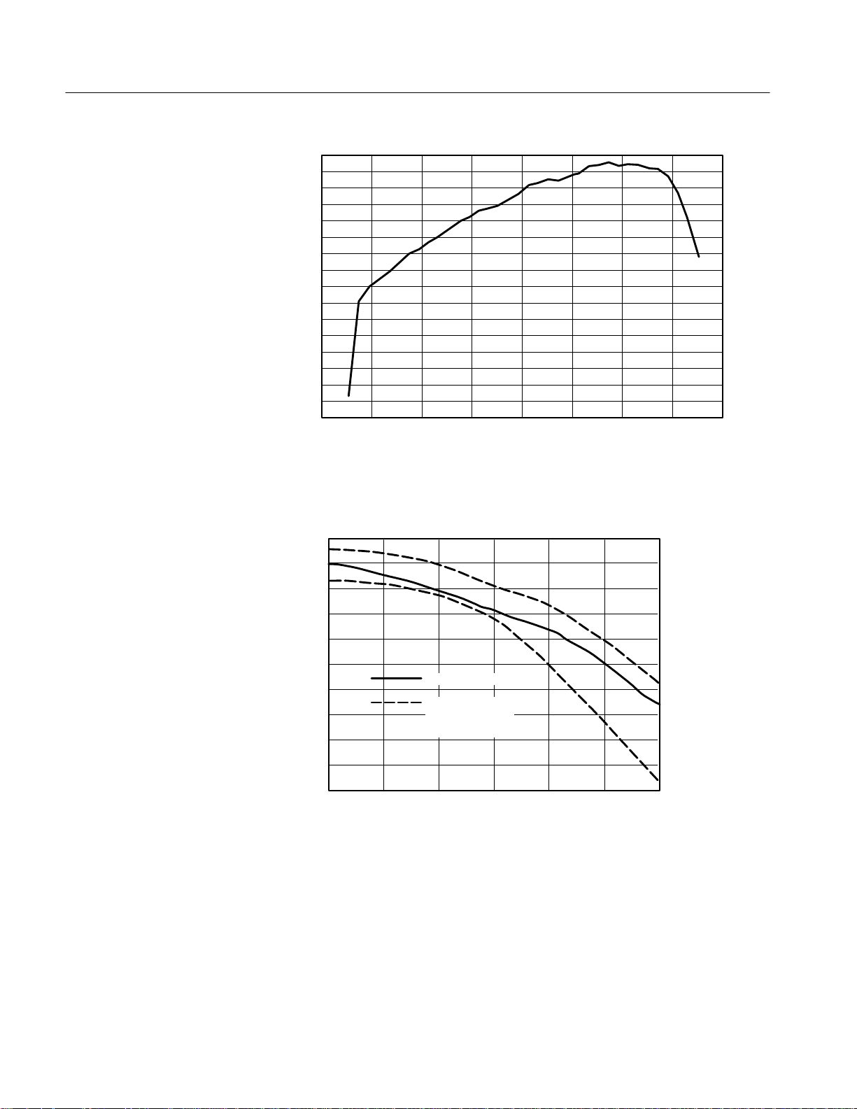
Relative responsivity, typical See Figure 6
Option RR frequency response, typical
(with OC-192 filter and SD-22)
Absolute maximum nondestructive optical
input
n Bandwidth, typical
Input fiber diameter Accepts 9 m single-mode diameter; Numerical Aperture (NA) ≤ 0.20
Internal fiber diameter core: 9 m single-mode fiber
Fiber connector style female FC/PC
Optical return loss > 30 dB minimum when external mating fiber is also single-mode PC style
≥ 15 mV / mW at 1310 nm ± 20 nm and 1550 nm ± 20 nm
See Figure 7
10 mW average power; 20 mW peak power at wavelength with highest relative
responsivity
DC to 30 GHz (– 6 dB electrical power into 50 ) for signals < 2 mW
cladding: 125 m
p-p
n Noise equivalent power
Impulse response width, typical ≤ 15 ps FWHM (Full Width Half Maximum)
Aberrations, typical ≤ 20%
n Output zero
External termination impedance 50 ± 2
Output impedance, typical Reverse terminated in 50 ± 2
Temperature Operating: +10_ C to +40_ C
Humidity 75% non-condensing
Altitude Operating: 4,572 m (15,000 ft)
≤ 15 pW Hzelectrical output noise when terminated into 50
total
p-p
≤ 1 mV
Non-operating: –55_ C to +75_ C
Non-operating: 15,240 m (50,000 ft)
SD-48 Instruction Manual
11
Page 22
Specifications
1.10
1.00
0.90
0.80
0.70
0.60
Relative conversion gain
0.50
0.40
0.30
1000 1200 1400 1600
Wavelength (nanometers)
Figure 6: SD-48 relative responsivity (normalized to 1310 nm)
2.0
0
–2.0
–4.0
–6.0
–8.0
dB
–10.0
–12.0
–14.0
–16.0
–17.8
0 2.5 5 7.5 10 12 15
Typical response
COM15-264E
recommended
response window
Frequency (GHz)
12
Figure 7: Typical frequency response, Option RR (SD-48, OC-192 filter, and SD-22)
SD-48 Instruction Manual
Page 23

T able 2: Certifications and compliances
Category Standards or description
Specifications
EC Declaration of Conformity –
EMC
Australia/New Zealand
Declaration of Conformity – EMC
Meets intent of Directive 89/336/EEC for Electromagnetic Compatibility. Compliance was
demonstrated to the following specifications as listed in the Official Journal of the European Union:
EN 55011 Class A Radiated and Conducted Emissions
EN 50082-1 Immunity:
IEC 801-2 Electrostatic Discharge Immunity
IEC 801-3 RF Electromagnetic Field Immunity
Complies with EMC provision of Radiocommunications Act per the following standard(s):
AN/NZS 2064.1/2 Industrial, Scientific, and Medical Equipment: 1992
SD-48 Instruction Manual
13
Page 24

Performance Verification
Use the following procedures to verify the warranted specifications of the SD-48
Optical-to-Electrical Converter. Before beginning these procedures, see page 21
and photocopy the test record and use it to record the performance test results.
The recommended calibration interval is one year.
These procedures test the following specifications:
Output zero
DC conversion gain
Noise equivalent power
Bandwidth/frequency response (for characterization purposes only)
Equipment Required
Table 3 lists the equipment required to perform the performance verification
procedure. The types and quantities of connectors may vary depending on the
specific equipment you use.
T able 3: Test equipment
Description Minimum requirements Example product
Optical power meter with
head and adapters
1310 nm cal source output > 200 W (CW)1,
1550 nm cal source output > 200 W (CW)1,
RF power meter noise < .1 mV, BW > 4 GHz HP 436A with power sensor
1300 or 1550 nm impulse
generator
Sampling oscilloscope with
sampling head
V–K adapter for use with SD-32 sampling head 011-0157-00
Accuracy ± 2.5%, dynamic range >
0 dbM to –50 dbM, Max power
> 1 mW, calibrated from 700 nm –
1600 nm
stability ± 0.1 dB over 5 minutes
stability > 0.1 dB over 5 minutes
pulse width < 2 ps Calmar Optcom FPL-01
HP 8153A with
HP 81532A head
BCP 400 A-2XXT-239
BCP 400 A-3XXT-239
HP 8484A
1550 nm impulser
11K (1180X, CSA80xX with
SD-32 sampling head, V-K
adapter and rigid cable.
Option RR also requires the
SD-22 sampling head.)
14
SD-48 Instruction Manual
Page 25

Performance Verification
T able 3: Test equipment (cont.)
Description Example productMinimum requirements
Rigid cable for use with SD-32 sampling head 174-3976-00
Reference receiver for
trigger source
PC with GPIB port and
printer
Two adjustable single-mode
optical attenuators
Digital voltmeter 4 1/2 digit Keithley 2000 or
50 termination ± 1% 01 1-0049-01
BNC-to-banana adapter BNC female to dual banana 103-0090-00
Optical cable (3) FC-FC singlemode, 9 m, 2
Inline optical adapter FC female to FC female 131-5039-00
1
CW and modulated mode available: modulation with OFF level at or below 0.1 W,
optical falltime < 1 s
trigger signal for sampling oscilloscope
printer output of sampled waveforms
4 decades, 9 m core fiber, FCstyle connectors
meters
10/90 or 50/50 splitter with
ORR24 or P6703B and
1103 TekProbe Power
Supply
T ektronix OA5002
T ektronix DMM916
174-1910-00
The O/E converter under test and the test equipment and should be warmed up
for 20 minutes at an ambient temperature between 20 and 30_ C.
Output Zero
DC Conversion Gain
SD-48 Instruction Manual
1. Attach the output of the SD-48 to the voltmeter inputs with a 50 W termina-
tion and BNC-to-banana adapter.
2. Install the optical dust cover on the input of the SD-48.
3. Check that output voltage is ≤ ± 1 mV. Record the result on the test record.
NOTE. Make sure that the optical connector ends of both the fiber from the
optical attenuator output and the SD-48 under test input fiber are well cleaned
before performing this step. See to the cleaning instructions on page 8.
1. Connect the 1310 nm laser source to attenuator input.
15
Page 26

Performance Verification
NOTE. The longer wavelengths of 1310 nm and especially 1550 nm in single
mode fiber are sensitive to loss in fiber due to bending of the fiber. The fiber
bend radius of the SD-48 fiber input should lay with >1.5 inch bend radius
along the fiber’s entire length. Although this precaution must be maintained
throughout the entire performance verification procedure, it is especially
important for this step in order to accurately adjust and measure the DC
conversion gain of the SD-48.
2. Connect the optical attenuator output to the optical power meter using single
mode optical cable with FC connectors. Use the appropriate optical power
meter sensing head with calibrated measurement for a wavelength span
including 1310 nm and 1550 nm. Be sure the optical power meter wavelength setting and optical attenuator setting is at 1310 nm. Enable the optical
output.
3. Adjust attenuator or the optical source so that the power meter reads
200mW.
4. Move the FC fiber end (the one now adjusted to 200 mW average power)
from the optical power meter and connect it to the SD-48 input under test.
5. Attach voltmeter with 50 W termination to SD-48 output.
6. Record the voltmeter reading. The 1310 nm Conversion Gain in units of
V/mW is
(voltmeter reading) × 5
7. Record the 1310 nm conversion gain on the test record.
8. Disconnect the 1310 nm laser from the optical attenuator, and reconnect the
1550 nm laser source. Set the optical attenuator to the correct wavelength.
NOTE. Do not disturb the fiber connection between the optical attenuator output
and the SD-48 input!
9. Adjust the optical attenuator until the voltmeter reading is the same as in
step 6 above ± 1%.
10. Without moving the optical attenuator from the position in the previous step,
disconnect the output fiber of the optical attenuator from the input of the
SD-48 and insert the optical attenuator output into the optical power meter.
11. Adjust the optical power meter to the calibrated wavelength setting of
1550 nm. Note the absolute power displayed. The 1550 nm conversion gain
in units of V/mW
opt
is
16
((200 W) / (measured 1550 power)) × (1310 nm conversion gain)
SD-48 Instruction Manual
Page 27

Noise Equivalent Power
Performance Verification
12. Record the 1550 nm conversion gain on the test record.
Power the SD-48 under test using an 11801 DSO.
1. Zero the RF power meter.
2. Connect the SD-48 electrical output to the RF power meter.
3. With the dust cover on the input to the SD-48, the power meter should read
less than
[(15 pW
ń HzǸ) 18 GHzǸ (measured conversion gain in VńW
opt
50 W
+ 8.1 10
+ W
elec
(NOTE : VńW
–14
(measured conversion gain in VńW
+ VńmW
opt
Example : 18 VńW
+ 8.1 10
W
elec
+ 2.6 10
1000)
opt
(or 0.018 VńmW) + measured conversion gain
opt
–14
(18 VńW
–11
opt
2
)
opt
2
)
+ 26 pW
4. Record the measured and calculated results on the test record.
opt
2
)]
SD-48 Instruction Manual
17
Page 28

Performance Verification
Bandwidth/Frequency Response
NOTE. The specifications for bandwidth and frequency response are typical and
are not guaranteed. The performance of each and every component of your setup
has an affect on the overall performance of your system. This procedure allows
you to characterize and plot the performance of your particular setup which
includes the channel of your sampling oscilloscope, sampling head, SD-48 O/E
Converter, electrical cable, and filter (if any).
To optimize performance, make sure all connections are properly cleaned and
secure and all components of the system are in good condition. Optical fiber, in
particular, can gradually degrade the system performance as it is repeatedly
flexed over time.
1. Connect the output of the optical impulse generator to the 10 dB inline
attenuator, 90/10 splitter, and optical attenuators as shown in Figures 8
and 9. Start with about 30 dB of attenuation on both variable attenuators.
NOTE. To avoid dispersing the narrow optical impulse signal, keep all fiber
lengths as short as possible. Lengths that are 2 to 3 meters long are acceptable.
2. To adjust the signal on the 10% path to the proper level you can use another
oscilloscope or you can use an optical power meter to measure the output of
the attenuator on the 10% path before you connect it to the ORR24.
NOTE. The setup necessary to attenuate the signal may vary depending on the
specific optical impulse generator you use.
a. If you are using another oscilloscope to display the trigger signal, adjust
the attenuation of the 10% path until the ORR24 produces more than
200 mV
b. If you are using an optical power meter, connect the output of the optical
attenuator on the 10% path to the optical power meter. With a pulse
width of 500 fs and a frequency of 10 MHz, adjust the optical
attenuator until the power meter reads about 1 mW average power.
3. Finish connecting the setup as follows:
a. For an SD-48 with the standard configuration, finish connecting the
setup as shown in Figure 8. Note that this requires an SD-32 sampling
head.
, but less than 1 V
p-p
impulse response.
p-p
18
SD-48 Instruction Manual
Page 29

Performance Verification
b. For an SD-48 with Option RR (OC-192), connect the equipment as
shown in Figure 9. Note that this setup requires an SD-22 sampling
head.
10dB attenuator
Optical
Impulse
Generator
Splitter fiber input Split 90% out fiber
Optical Split
Split 10% out fiber
Variable optical
attenuator
90%
10%
SD-48
In Out
Variable optical
attenuator
ORR24
In Out
V–K adapter
J–cable
(174-3976-00)
Figure 8: Setup for frequency response measurement, SD-48 standard configuration
10dB attenuator
Splitter fiber input Split 90% out fiber
Tek 1180X
SD32
or CSA80X
scope
Ext Trig inputSMA–cable
Optical
Impulse
Generator
Split 10% out fiber
Optical Split
10%
Variable optical
Variable optical
attenuator
90%
attenuator
SD-48
In
ORR24
In
Out
Out
OC-192
filter
SMA–cable
(015–0560-00)
Figure 9: Setup for frequency response measurement, SD-48 Option RR for OC-192
4. Set the trigger point midway on the rising edge of the trigger signal.
SMA
“barrel”
SD22
Tek 1180X
or CSA80X
scope
Ext Trig inputSMA–cable
SD-48 Instruction Manual
19
Page 30

Performance Verification
5. Adjust the attenuation of the 90% path until the SD-48 produces more than
30 mV
, but less than 80 mV
p-p
impulse response.
p-p
6. Locate and center the first impulse (after time zero) on the oscilloscope
display. (For a 10 MHz repetition rate, the impulse should occur at about
100 ns. You may experience signal jitter if you try to display a signal that is
not the first impulse and is late in relation to time zero.)
7. Finish setting the oscilloscope controls as follows:
a. For an SD-48 with the standard configuration, set the horizontal time to
50 ps/div, set the vertical controls for maximum screen usage, and set the
signal averaging to 64 times and 2048 points.
b. For an SD-48 with Option RR (OC-192), set the horizontal time to
100 ps/div, set the vertical controls for maximum screen usage, and set
the signal averaging to 64 times and 2048 points.
8. Using a controller attached to the scope via GPIB (i.e. a PC, MAC,
workstation, etc.) download the waveform.
9. Using the available controller software (i.e. Labview, etc) perform an FFT
(Fast Fourier Transform) on the waveform; this transforms the time-domain
(1024-point) impulse response to a scalar frequency response.
10. Normalize the FFT result such that DC or low frequency is 0 dB.
11. Plot the frequency response. (Option RR comes with tabular data at discrete
frequency points.)
This completes the performance verification procedure.
20
SD-48 Instruction Manual
Page 31

Performance Verification
T est record
Model/Serial Number: Certificate Number:
Temperature: RH %:
Date of Calibration: Technician:
Performance test Minimum Measured Maximum
Output zero N/A ±1 mV
DC conversion gain at 1310 nm ± 20 nm 0.015 V/mW N/A
DC conversion gain at 1550 nm ± 20 nm 0.015 V/mW N/A
Noise equivalent power
Bandwidth/frequency response, standard,
DC to 30 GHz
Bandwidth/frequency response, Option RR (OC-192),
DC to 15 GHz
1
Frequency response plots are for characterization purposes only. Specifications for bandwidth and frequency response
are typical and are not guaranteed.
N/A _______W
(calculated)
N/A (attach plot1) N/A
N/A (attach plot1) N/A
elec
SD-48 Instruction Manual
21
Page 32

Replaceable Parts
For information about replaceable parts, contact your Tektronix sales representative.
1
Figure 10: SD-48 replaceable parts
3
2
22
SD-48 Instruction Manual
Page 33

Replaceable Parts
1 2 3 4
8
9
Option RR only
Figure 11: Standard accessories
1 2
5
7
6
3
4
Figure 12: Optional accessories
SD-48 Instruction Manual
5
6
9
8
7
23
Page 34

Replaceable Parts
1
2
3
4
5
Figure 13: Optional power cords
Replaceable parts list
Fig. &
index
number
10–1 211–0062–00 1 SCREW,MACHINE:2–56 X 0.312,PNH,STLCD PL,POZ 93907 ORDER BY DESCRIP
–2 200–3658–00 1 COVER,CONNECTOR:FC,W/CHAIN 80009 200–3658–00
–3 015–1020–00 1 TERM,COAXIAL:SHORT CIRCUIT,SMA 0GZV8 64SMA–50–0–1
11–1 131–6252–00 1 CONN:FC TO FC SQUARE MOUNT
–2 131–6250–00 1 CONN:FC T O ST ADAPTER W/ZIRCONIA CERAMIC
–3 131–6251–00 1 CONN:SC TO FC SQUARE FLANGE ADAPTER
–4 174–1910–00 1 CA ASSY FBR OPT:SM 2ML FC/PC TO FC/PC 05JW7 SGMGM–AA0002
–5 015–0560–00 1 CABLE,DLY,COAX:50
–6 174–3828–00 1 CA ASSY,RF:COAXIAL,RFS,50 OHM, SMA X SMA 060D9 174–3828–00
–7 174–3976–00 1 CA ASSY,RF:SEMI–RIGID,RFS,1,50 OHM,0.141
–8 119–5916–00 1 FILTER:LOW PASS,OC192 for SD48/SD22 80009 119–5916–00
–9 015–1011–00 1 ADAPTER,CONN:SMA,MALE TO SMA,MALE,SST 16179 2081–0000
12–1 016–1609–00 1 POWER CORD KIT:ADAPTER CABLE & US POWER
–2 119–5118–00 1 ATTEN,OPTICAL:30MM,L10DBFOR 1310/1550NM,FC
–3 015–0565–00 1 POWER DIVIDER:50 OHM,3 SMA,FEMALE CONN 64537 D293S
–4 020–2209–00 1 ACCESSORY KIT:CONNECTOR,OPTICAL,DIN RCPT
Tektronix
part number
071–0207–00 1 MANUAL,TECH:INSTRUCTION 80009 071–0207–00
015–1014–00 1 PWR DIVIDER,RES:50 OHM,SMA 64537 D241S
Serial no.
effective
Serial no.
discont’d
Qty Name & description Mfr. code Mfr. part number
Standard accessories
ADAPTER,W/ZIRCONIA CERAMIC SLEEVE
SLEEVE
W/ZIRCONIA CERAMIC SLEEVE
OHM,2NS,W/CONN,SMA,MALE,EACH END
SEMI–RIGID,(SMA CONN) BOTH ENDS,
0C5R7 CO92290
0C5R7 C032980
0C5R7 C002453
0GZV8 SF104PE,460MM,2X1
1SMA–451
060D9 174–3976–00
Additional accessories with Opt. RR
Optional accessories
CORD
CONN.FA100–35–10–HP
TO FC SQUARE MOUNT ADAPTER,
80009 016–1609–00
0LK97 FA100–35–10–HP
80009 020–2209–00
24
SD-48 Instruction Manual
Page 35

Replaceable Parts
Replaceable parts list (cont.)
Fig. &
index
number
–5 174–3737–00 1 FIBER OPTIC:COUPLER, 1 X 2 SPLITTER,
–7 119–5916–00 1 FILTER:LOW PASS, 10GBS 80009 119–5916–00
–8 011–0157–00 1 ADPTR,RF,PRCN::2.4MM OR 1.85MM MALE TO
–9 015–1011–00 1 ADAPTER,CONN:SMA,MALE TO SMA,MALE,SST 16179 2081–0000
13–1 161–0066–09 1 CA ASSY,PWR:3,0.75MM SQ,250V/10A,99
–2 161–0066–10 1 CA ASSY,PWR:3,1.0 MM SQ,250V/10A,2.5
–3 161–0066–11 1 CA ASSY,PWR:3,1.0MM SQ,250V/10A,2.5
–4 161–0066–12 1 CA ASSY,PWR:3,18 AWG,250V/10A,98
–5 161–0154–00 1 CA ASSY,PWR:3,1.0MM SQ,250V/10A,2.5
Tektronix
part number
174–1497–00 1 CA ASSY,FBR OPT:SINGLE MODE,2M L
174–1385–00 1 CA ASSY,FBR OPT:SGL MODE,2M L,FC/PC
174–1386–00 1 CA ASSY,FBR OPT :SINGLE MODE,2M L,FC/PC–ST 80009 174–1386–00
174–1387–00 1 CA ASSY,FBR OPT :SGL MODE,2M L,FC/PC–FC/PC 80009 174–1387–00
174–1388–00 1 CA ASSY,FBR OPT:SGL MODE,2M
119–5929–00 1 FILTER,RFI:LOW PASS,467MHZ –3DB,622.08
119–5936–00 1 FILTER,RFI:LOW PASS,1 17MHZ –3DB,155.52
Serial no.
effective
Serial no.
discont’d
WA VELENGTH INDEPENDENT, 90/10 RATIO, ATT .
0.1 DB, REFLE
FC/PC TO DIAMOND 2.5
DIAMOND3.5
L,FC/PC–BICONIC
MBPS,INS LOSS < 0.02 DB,VMAX=50V,IMAX=1A,50
OHM
MBPS,INS LOSS < 0.02 DB,VMAX=50V,IMAX=1A,50
OHM,SDH
2.92MM FEMALE
Optional Power Cords
INCH,STR,IEC320,RCPT,EUROPEAN,
METER,STR,IEC320,RCPT X 13A,FUSED UK
PLUG(13A FUSE),UNI
METER,STR,IEC320,RCPT,AUSTRALIA
INCH,STR,IEC320,RCPT X NEMA 6–15P,US
METER,STR,IEC320,RCPT,SWISS
Mfr. part numberMfr. codeName & descriptionQty
0C5R7 C166893
80009 174–1497–00
80009 174–1385–00
80009 174–1388–00
80009 119–5929–00
80009 119–5936–00
20944 34VKF50
2W733 ORDER BY
DESCRIPTION
TK2541 ORDER BY
DESCRIPTION
80126 ORDER BY
DESCRIPTION
S3109 ORDER BY
DESCRIPTION
5F520 86515030
SD-48 Instruction Manual
25
Page 36

Replaceable Parts
Manufacturers cross index
Mfr.
code
05JW7 PURDY ELECTRONICS CORP INTEROPTIC DIVISION
060D9 UNITREK CORPORATION 3000 COLUMBIA HOUSE BLVD,
0C5R7 ALCOA FUJIKURA LTD 150 RIDGEVIEW CIRCLE DUNCAN, SC 29334
0GZV8 HUBER & SUHNER INC 19 THOMPSON DRIVE ESSEX JUNCTION, VT 05452–3408
0LK97 JDS FITEL INC 570 WEST HUNT CLUB RD NEPEAN, ONTARIO CA ONT ARIO K2G 5W8
16179 M/A COM INC 1011 PAWTUCKER BLVD.
20944 ANRITSU COMPANY 685 JARVIS DRIVE MORGAN HILLS, CA 95037
2W733 BELDEN WIRE & CABLE COMPANY 2200 US HWY 27 SOUTH
5F520 PANEL COMPONENTS CORP PO BOX 115 OSKALOOSA, IA 52577–0115
64537 KDI/TRIANGLE ELECTRONICS INC 60 S JEFFERSON RD WHIPPANY, NJ 07981
80009 TEKTRONIX INC 14150 SW KARL BRAUN DR
80126 PACIFIC ELECTRICORD CO 747 WEST REDONDO BEACH
93907 CAMCAR DIV OF TEXTRON INC ATTN: ALICIA SANFORD
S3109 FELLER U.S. CORPORATION 72 VERONICA AVE
TK2541 AMERICOR ELECTRONICS LTD UNIT–H
Manufacturer Address City, state, zip code
720 PALOMAR AVE
SUITE 120
PO BOX 3295
PO BOX 1980
PO BOX 500
PO BOX 10
516 18TH AVE
UNIT #4
2682 W COYLE AVE
SUNNYVALE, CA 94086
VANCOUVER, W A 98661
LOWELL, MA 01853–3295
RICHMOND, IN 47374
BEAVERT ON, OR 97077–0001
GARDENA, CA 90247–4203
ROCKFORD, IL 611045181
SOMERSET, NJ 08873
ELK GROVE VILLAGE, IL 60007
26
SD-48 Instruction Manual
 Loading...