

Page 1

I,
Checks
and
Adjustments
This section
limits
beginningofeach
the
SD-24
section providealogical
performance
specifications.Tofunctionally
lable
Refertothe
more
Table
Part
Part1Power-On
Part2Dot
250mywith automatic
calibration
500mywith
calibration
contains
listedinTable
TDR/Sampling
verification
2-1
which
SD-24
Information about
2-2
for
information
Table
and
Description
Itansient
procedurestocheck
2-1. The
part
havea“yes”
TDRISamp!ing
2-1
Response
automatic
SpecificationorMeasurement
as well.
Head
sequenceofchecks
proceduretoverify
specifications
concerning
Measurement
the
specifications
These
procedures
hasnointernal
test
the
sampling
indicationinthe
Head
Installation/User Reference
and
sampling head
test equipment
Limits
Measurement Specification
Umit
none none
59~
error
59~
error
contain only
adjustments.
for
performingacomprehensive
that
the
sampling
head, perform
Functional
usedinthe
and Specifications
and
measurement
LimitIslistedatthe
check
steps,
The
padsinthis
head
meets
the
parts
In
Test
Column.
manual
operation.
Refer
setups.
Functional
Test
yes
yes
no
since
for
to
4
500mywith default
settings
1.0 V
without
calibration
Pan3Offset
Offset
Offset
change
repetition rate
Part
4 Noise
Smoothing,
Smoothing,
Part4Noise
Smoothing,
Smoothing,
Part5Rise
(SN
(SN
lime
automatic
with
8020652
on
off
8010651
on
off
and
and
.
±20%
±2
mV
above)
550
1.2my
beiow)
900
2
my
error
pM
rms
mis
sV
rrns
rms
adjusted
100% at1V
±5
17.5
to
my
ps
no
no
yes
no
no
no
.
yes
SD-24
Service
Reference
REV
Nov
1989
2-1
Page 2
- . <
. . .--..e
-m.-.. .
TEK . INTER-OFFICE COMlvllJNlCATlON .-
.
TO
FWW
M3KC.T
Sohn Martin
Frank Gray, SO-PAT
GIDEP
permit request
In response to
Government
Tektronix
Tektronix, Inc.
of
such documents to any
in the
that all copies
copyright
in
pemieeion,a
Metrology
the
original, together with the Legend "Reproduded with
Industry
operator,
hereby grant6 such permission for distribution
of the
notice
Data
and ownership statement exactly a-& it appears
This permission has
Committee of
aeon%
1[
ded
to GIDEP to provide'the
94-540
the
request to grant permission to
Exchange
service and
Pro
GTDEP
ram
P
nstruction manuals,
user that is a full participant
Interchange Data Base
original
been
Tektronix
work include the
approved by
and
requested permission.
3:. ' t
(GPDEP) to reproduce
of
the
a
copy of this memo may
Juno 25, 1991
the
GIDEP provided
entire
Intellectual
g:&dy
Group Pat&t Coun&al
Page 3
Checks
and
AdJusW7ents
Table
Part
and
Description Measurement Specification
Part
6 Acquisition
(with
067-1338-00
Oto300ps
300psto5ns
SnstolOOns
100nsarid
—lOnsto—2Ops
Part
7 Coincidence
Channels
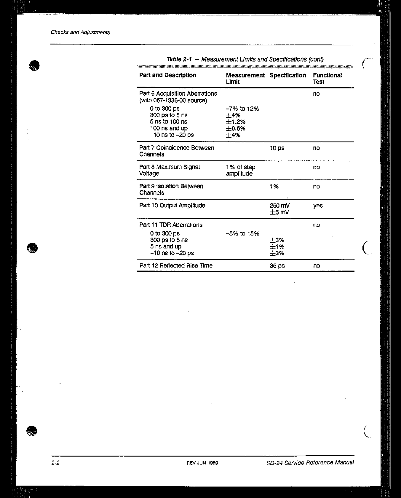
2-1—Measurement Limits
Limit
Aberrations
source)
-7%tol2%
±4%
±1.2%
up
+0.6%
±4%
Between
and
Specifications
10
Ps
(cont)
Functional
Test
no
flO
S
Part8MaxImum
Signal 1%ofstep
Voltage
Part9Isolation
Between
channels
Part10Output
Part11TDR
Amplitude
Aberrations
Oto300ps
300psto5ns
Snsandup
—lOnsto—2Ops
Part12Reflected
Rise
Time
amplitude
—5%tolS%
•
1%
.
250
my
+5mV
±3%
±1%
±3%
35
Ps
no
no
yes
no
.
C
no
2-2
REV
JUN
1959
SD-24
Seniice Reference
(~.
Manual
Page 4
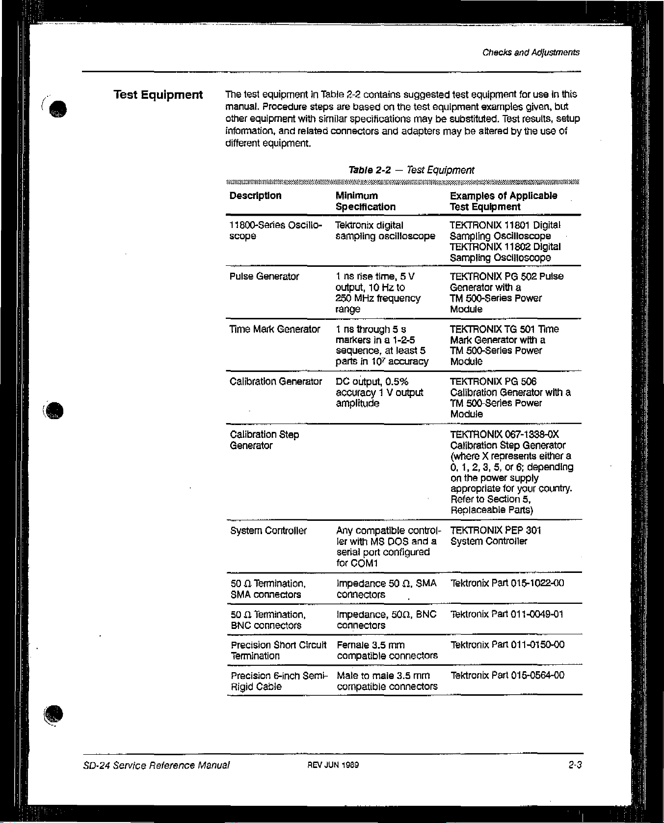
Test
Equipment
The
test
equipmentinTable
manual.
other
Procedure
equipment
information,
different
equipment.
and
steps
with
similar
related
2-2
contains suggested test
are
basedonthe
specitications
connectors
Table
2-2
and
—
equipment
test
equipment examples
maybesubstituted.
adapters
Test
maybeaiteredbythe
Equipment
Checks
and
Test
Adjustments
for useInthis
given,
but
results,
use
setup
of
4
DescriptIon
11800-Series
Oscillo-
scope
Pulse
Generator
Time
Masl
Generator1ns through 5 s
Calibration
.
Calibration
Generator
Step
Generator
Minimum
SpecificatIon
Tektronix
sampling
1nsrise
output,10Hz
250
digital
oscilloscope
tIme,5V
Mhz
frequency
to
range
markersIna
1-2-5
sequence,atleast
partsin10~
DC
othput,
accuracy1V
accuracy
0.5%
output
amplitude
ExamplesofApplicable
Test
Equipment
TEKTRONIX
Sampling
TEKTRONIX 11802
Sampling
11801
Digital
Oscilloscope
Digital
Oscilloscope
TEKTRONIXPG502 Pulse
Generator
TM
with
a
500-Series Power
Module
TEKTRONIXTG501
Mail<
Generator
5
TM
500-Series Power
with
Time
a
Module
TEKTRONIXPG506
Calibration
TM
500-Series
Generator
with
Power
a
Module
TSCTRONIX 067-1338-OX
Calibration
(whereXrepresents either
0, 1,
on
the
appropriate
!
Refer
Replaceable
Step
2,3,5,ore:
power
supply
for
your
to Section
Parts)
Generator
a
depending
country.
5,
SD-24
Serv/ce
Reference
Manual
System
Controller
Any
ler
serial
for
soaTermination,
SMA
connectors
50aTermination,
BNC
connectors connectors
Precision
Short
Circuit
Termination
Precision
Rigid
6-Inch
Cable
Semi-
REV
Impedance50(1.
connectors
Impedance,
Female
compatible connectors
Maletomale 3.5
compatible connectors
JUN
compatible
withMSDOS
port
configured
COM1
3.5mm
1989
control-
50(1,
and
SMA
BNC
mm
TEKTRONIX
a
System
Tektronix
Tektronix
Tektronix
Tektronix
PEP
301
Controller
Part
015-1022-00
Part
011-0049-01
Part
011-0150-00
Part
015-0564-00
.
2-3
Page 5

Checks
and
Adjustments
table
2-2—Test
Equipment
(cant)
S
S
Description Minimum
Specification
Short
Circuit
Terminators,
Connections
(2
required)
Coaxial
(2
required)
Serial
Adapter,
(2
required)
Attenuator, 2X
Attenuator, 5X
Wrist
Strap
Static
Needle-nose
SMA
Cable,
Cable
SMA
Control
so
to BNC
Mat Tektronix
pliers
Male
SMA
a
so
a,
BNC
connectors
10-ft
R5-232-Q Cable
SMA
male
female
6dBattenuation,
one
male
female
14dB
50
LI,
one
female
36-Inch, male
BNC
attenuation,
one
Connectors
to BNC
50
£2,
and one
male
and
BNC
ExamplesofApplicable
Test
Equipment
Tektronix
Tektronix
Tektronix
Tektronix
Tektronix
TektronIx
Tektronix
Part
015-1020-00
Part
012-0482-00
Part
012-0911-00
Part
015-0554-00
Part
011-0069-02
Part
011-0080-02
Part
008-3415-00
Part
006-3414-00
.
(
Pozidrive
S
ScrewdriverP1tip
(.
2-4
REV
JUN
1939
SD-24
SeN/ce
Reference
Manual
Page 6

Checks
and
Adjustments
5
UsingThese
Procedures
Each
part
begins
needed
and
equipment
ConventionsInthis
In
these
procedures, the
•
CAPITAL
and
connectors
withasetup
howtoconnect
for
each
part.
Manual
letters
within
(for
example,
illustration
It.
RefertoTable
following
the
bodyoftext
conventions
MEASURE)onthe
head.
•
Hold
letters
•
initial Capital
example,
Identify
In
some
performance
Is
the
Adjust
the
firm
adjustments
steps,
verification and/oranadjustment
first
wordInthe
appearsinthe
wordinthe
identify
Position)onassociated test
the
menu
labels
and
letters
identify connectors, controls,
inside
the
sampling
first
wordisitalicizedtoidentifyastep
titleofa
title,
title,
step,anelectrical
the
step
involvesanelectrical
the
step
concerns
whether the sampling headIsoperating
interpretedas!lectrical
specifications.
that
shows
2-2
identify
what test
foranexampleofthe
are
used:
front panel
oscilloscope
display
messages.
and
equipment.
Initial
head.
instruction.
specIficationischecked.
measurement limits
properly; these
limits
equipment
is
test
controls,
indicators
Capital
that
contains
For
example,ifCheck
indicators,
and
sampling
(for
letters
a
also
If
adjustment.IfExamine
that
Indicate
are
nottobe
is
initialized
At
the beginningofmost steps,
as
part of
presets
oscilloscopeatthe
previous
Menu
Detailsonmeasurement
are
and
thel
Installation/User
Tutorial
The
Introducing
to tamiharize
and
Stored
the setup,
all
oscilloscope
beginningofa
parts
causing
Selections
generally not
oscilloscope
1802
User
and
includedInthis
features
Reference
manual.
Manual
tutorial manuals,
thel
1802
the
first-time
Settings
The
initIalIze
controls
erroneousorconfusing results.
Measurement
techniques
IntroducIng
Digital
features.
the
feature,
and
manual.
are
locatedinthe
manual,
the
Sampling
user
with
userisinstructedtoInitialize
available through
the
functionstoknown values.
step
eliminates
the
possibilityofsettings
lbchnlques
and
instructions
Comprehensive
11801 User
and
the
SD-24
11801
Digital
Oscilloscope,
11801
and
for
making
descriptionsofmenus
Reference
TDR/Sampling
Sampling
are
strongly
11802
Oscilloscope
Oscilloscope
the
oscilloscope
UTILITY
Initializing
menu,
the
tom
menu
selections
manual,
Head
and
recommended
controls
and
SD-24
SeN/ce Reference
Manual
REV
JUN
1989
2-5
Page 7

Part
1
Power-on
Perform
assure
this
part
proper
within
oscilloscope
SetuptoPower-on
11801
the ambient temperature
range
operation.
Of
+
installed
C/i~cks
18
(not
yet)
and
and+28~C,to
0
Adjustments
(
ProceduretoPower-on
~
Step1:Set
Sampling
11801/11802
ON/STANDBY
fl
Step
2:
the
followingInthe
head
Oscilloscope
switch
Install
an
SD-Series
compartment,
~
Step3:With
to
OFF,
the
oscilloscope’s
connect the
SeWp10Power-on
order
sampling
rear
11801/11802
Oscilloscopetoa
0
(not
lnstalI~d
yet)
listed:
Not
installed
headinthe osculoscopes
panel
PRINCIPAL POWER
suitable
power
yet
STANDBY
left-most
SWITCH
set
source.
(
2-6
~
Step4:Set
oscilloscope’s
the
rear
panel
front panel
REV
JUN
PRINCIPAL POWER
ON/STANDBY SwitchtoON.
198~
SD-24
SWITCHtoON
Service
Reference
and
then
Manual
the
Page 8

PartIPower-on
When the
11801/11802
PRINCIPAL
Then,
use
the
power
switching.
E
Step5:Power-on
the
oscilloscopetobe
•
Calibration generator
•
Calibration step generator
•
Time mark
•
Pulse
generator
A
complete
•
Allow
a20mInute
before
POWER
front
panel
the
generator
lIst of
test equipmentislistedinTable 2-2.
doing
the
OscilloscopeIsfirst
SWITCH
shouldbesettoand
ON/STANDBY
following
test
tested:
warm-up for
performance
the
checks.
installed, the rear
remainintheONposition.
switch
to perform
all
equipment,sothatitIs
Sampling
head
and
panel
subsequent
warmedupwith
test
equipment
50-24
Service Reference
REV
NOV1989
2-7
Page 9

Dot
Transient
Response
Part
Checks
This
part
2
shows
response.The
automatic calibration
with
manual
the
setup
dot
transient
settings,at500mywith default
calibration
and
lists
the
procedurestocheck
responseisexaminedat250myand
settings, and
settings.
the
dot
500mywith
and
Adjustments
transient
checked
at
Measurement
The
measurement
5
% error
LimIts
when
settings
•
20%
error
when
Specifications
The
specification
adjustable
Setup to
Check
for
to 100%
Dot
limits
for
the dot
transient
measuredat250myand 500
measuredat500
the dot
transient
Transient
my with
responseat1
Response
response
my with
default
V
error
is that
are:
automatic
the
amplitude
calibration
is
Check
Dot
Transient
2X
Attenuator
(not
connected
Response
SD-24
yet)
Service
Reference
Manual
Page 10
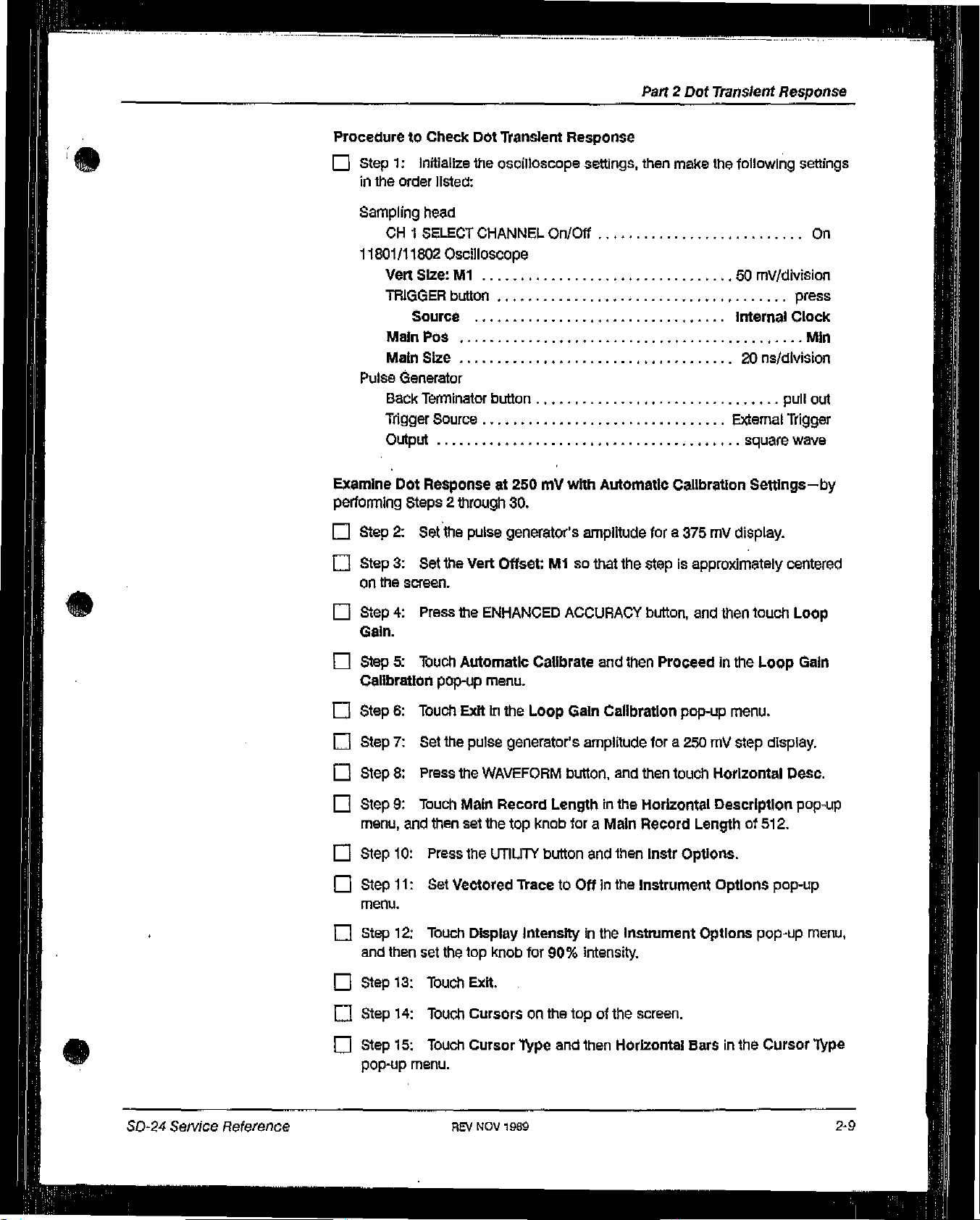
Part2Dot
Transient
Response
ProceduretoCheck
C
I,
Step1:initialIze
in
the
order
Sampling
OH1SELECT
11801/11802
VertSlze:M1
TRIGGER
Source
Main
Main
Pulse
Generator
Back
Tagger Source
Output
Examine
performing
Q
Dot
Steps2through
Step2:Set
head
Poe
Size
Terminator
Response
Dot
‘Tpanslent
the
oscilloscope
listed:
CHANNEL
Oscilloscope
button
button
at 250mywith
30.
the
pulse
generator’s amplitude
Response
settings,
On/Off
Automatic
make
the
then
Calibration
fora375mVdisplay.
following
50
mV/dMsion
Internal
20
ns/dlvision
External
square
Settings—by
settings
On
press
Clock
Mm
pull
out
Trigger
wave
o
Step3:Set
on
the
C
Step4:Press
Gain.
fl
Step5:ibuch Automatic
Calibration
o
Step6:Touch
o
Step7:Set
o
Step8:Press
o
Step9:Touch
menu,
D
Step
10:
~
Step
11:
menu.
0
Step
12:
and
then
~
Step
13:
The
screen.
pop-up
the
and
then
Press
Set
Touch
set
the
Touch
Vert
the
Exitinthe Loop
pulse
the
Main
set the
the
Vectored
Display
top
Exit,
Offset:
ENHANCED
menu.
WAVEFORM
Record
UTIUTY
knob
Mlsothat
ACCURACY
Calibrate
generator’s amplitude
Lengthinthe
top
knob
button
itacetoOffInthe
Intensityinthe
for
90%
and
Gain
button,
foraMain
and
intensity.
the
stepisapproximately
button,
then
Calibration
fora250mVstep
and
then
Horizontal
Record
then
instr
Instrument
instrument
and
Proceedinthe
pop-up
touch
Lengthof512.
Options.
Options
centered
then
touch
Loop
menu.
display.
Horizontal
Description
Options
Desc.
pop-up
pop-up
Loop
Gain
pop-up
menu,
SO-24
Service
Reference
o
o
Step
14:
Step
15:
pop-up
Touch
Touch
menu.
Cursorsonthe
Cursor Type
REV
NOV
1969
topofthe
and then
screen.
Horizontal
Barsinthe
Cursor
Type
2-9
Page 11
Part
2
Dot
Transient
S
Response
C
C
C
o
C
C
C
C
o
C
C
Step
16:
Step
17:
before
the
Step
18:
Step
19:
valueasV
Step
20:
Step
21:
Gain
CalibratIon
Step
22:
pop-up
Step
Step
Step
step,
Step
menu.
23:
24:
25:
26:
Touch
Exit.
Set
Cursor1(top knob) to
step.
Set
Cursor
Read~Vas
for
later
Press
Touch
Set
the
touch
Touch
Set
Cursor1to
Set
Cursor2to
2 (bottom
the peak-to-peak
use.
the
ENHANCED ACCURACY
Loop
Gain
pop-up
Dividebyiwo
Exitinthe
Cursorsatthe topofthe
menu,
the
the averageofthe
the
averageofthe
knob) to
and
then
ModetoOninthe Loop
Loop
Gain
averageofthe
the topofthe
step amplitude,
the
channel
Calibration
screen,
bottomofthe
step.
and
button.
you
are
pop-up
bottomofthe
bottomofthe
then
record
usingInthe
Gain
Calibration
menu,
pulse
before
pulse
under
pulse
this
Loop
the
the
step.
C
Step
27:
C
Step
28:
C
Step
29:
o
Step
30:
is
5%
C
Step
31:
(V—Vt.)]
Examine
perfonTling
o
C
C
o
Step
Step
Loop
Step
Step
Dot
Steps31through
32:
33:
Gain
34:
35:
Read
AV,
Set
Cursor2to
Read
ExamIne
ExamIne
is
5%.
Response
Press
Touch
Calibration
Touch
Set
the
and
then
record
the averageofthe topofthe
AV,
and
then
that
the
negative
that
the
positive
at
500
my
50.
the
ENHANCED ACCURACY
Loop
Gain,
and
pop-up
Exit.
Vert
Slze:M1to100
record
dot
dot
with
then
menu.
this
this
Automatic
valueasVL for
valueasVH
response
response
Calibration
button.
set
Dividebyiwo
mV/div.
later
use,
pulse.
for
later
use.
en’or
((—VL/VH)x100%]
error
(100%x
Settings—by
ModetoOffinthe
(
(Vii--V)/
——
C
Step
36:
Set
the
o
Step
37:
Touch
E
Step
38:
Set
Cursor1to
step.
2-10 SEV
puise generator’s
Cursorsonthe
NOV1989
topofthe
the averageofthe
amplitude
screen,
bottomofthe
fora500mystep
pulse
Checks and
display.
before
the
Adjustments
Page 12

C
Step
C
Step
valueasV
C
Step
C
Step
the
C
Step
pop-up
C
Step
C
Step
step.
o
Step
step.
C
Step
39:
40:
41:
42:
Loop
43:
menu.
44:
45:
46:
47:
Set
Cursor2to
ReadSVas
for
later
use.
Press
the
ENHANCED
Touch
Loop
Gain
Calibration
Set
Divide
Touch
Cursorsatthe
Set
Cursor1to
Set
Cursor2to
Read
theAVvalue,
Part2Dot
the
averageofthe
the peak-to-peak
ACCURACY button.
Gain and
by
iwo
then
the
pop-up
the
the averageofthe bottomofthe
menu.
Modetooninthe
topofthe
averageofthe
and
then
tO~
step amplitude,
channel
screen.
bottomofthe
record
of
the pulse.
number
Loop
this
value as
Transient
and
you
Gain CalibratIon
then
are
pulse
pulse
Vt.
for
Response
record
using
before
after
the
later
this
in
the
use.
o
Step
fl
Step
C
Step
is
5%.
C
Step
(V—VL)]is5%.
Examine
51
through
C
Step
C
Step
Calibration
C
Step
C
Step
C
Step
step.
C
Step
step.
48:
Set
49:
Read
50:
ExamIne
51:
Examine that
Dot
Response
59.
52:
Press
53:
Touch
54:
Touch
55:
touch
56:
Set
57:
Set
Cursor2to
~V,
and
that
the
ENHANCED ACCURACY
Loop
pop-up
menu.
Exit,
Cursorsatthe
Cursor1to
Cursor2to
the
averageofthe
then
record
the
negative
the
positive
at 500mVwith
Gain and
then
topofthe
the averageofthe
the averageofthe
topofthe pulse.
this valueasVH
dot
response
dot
response error
default settings—by
button.
Recall
Defaultsinthe Loop
screen.
bottomofthe
bottomofthe
for
error
(100
iater
use.
R—VL/VH)x100%]
%
x
(VH—V)/
performing
puise
pulse
Steps
Gain
before
after
the
the
80-24
Service
Reference
C
C
Step
58:
Step
59:
Record
Read
Set
this
valueasVii,
the~Vvalue,
Cursor2to
REV
NOV
1989
and
then
record thIs
the
averageofthe topofthe
valueasVt.
pulse
for
and
later
read
use.
~V,
2-11
Page 13
Pafl2Dot
Transient
Response
C
Step
60:
[(-VL/VH)x
Examine
that
100%]Is20%.
the
magnitudeofthe
negative
dot
response
error
(
Check
Steps60through
C
C
C
C
C
o
C
C
C
o
Dot
Responseat1V
Step
61:
Press
Step
62:
Touch
the
Loop
Gain
Step
63:
Touch
Step
64:
Remove
the channel
Step
65:
Step
66:
Step
67:
Step
68:
the
Loop
Step
69:
CalibrateInthe
Step
70:
you
Set
Set
Press
touch
Gain
Set
Thuch
70.
the
ENHANCED
Loop
Gain,
Calibration
Exit.
the
5X attenuator,
are
using
the
Vert
Size:M1
the
pulse
the
ENHANCED ACCURACY
Loop
Gain and
Calibration
the
Dividebyiwo
Loop
Gain
Exit.
with
Manual
and
pop-up
and
the
generator’s amplitude
pop-up
Calibration
Calibration
ACCURACY
then
set
the
menu.
and
then
coaxiai
to 200
then
menu.
ModetoOn,
cable,
mv/div.
the channel
pop-up
button.
Dividebyiwo
button.
Settings—by
connect
fora1
and
menu.
the2Xattenuator
v
*2%
number
then touch
perfomling
ModetoOff
step
you
are
Manual
to
display.
using
In
In
(
C
C
Step
of
the
with
Step
71:
Check
level under
the
manual
72:
Repeat steps
that
the
amplitude
the
pulsetothe
calibration
2 through71for
of
the
averageofthe
settingstobe
pulse,
~1V
channel
measured from
topofthe
2.
pulse,
the average
canbeset
2-12
REV
NOV
1989
Checks and
Adjustments
Page 14

1,
Part 3
Offset
This
part
offset
shows
change
the
with
setup
and
repetition
lists
rate.
the
procedure
to examine
offset
and
check
Measurement
The
measurement
LImItS
limit
Specifications
The
specification
for
SetuptoExamine
for
the
offset
Offset
the
offsetis±2
change
with
CH1
my.
repetition
CH
rate
50(1
Tem7inaUon
1
50(1
Is
±5
TermlnaUQn
mV.
50-24
Se,vice
Reference
ProceduretoExamine
0
Step1:InitialIze
in
the
order
Sampling
head
CH1SELECT
11801/11802
TRIGGER
the
listed:
CHANNEL
Oscilloscope
button
Source
ENHANCED ACCURACY
Calibrate All
REV
NOV
Setup
Offset
oscilloscope
On/Off
button
pop-up
1989
menu
to
Examine
settings,
Offset
then
make
the
following
internal
Recall
settings
On
press
Clock
press
Defaults
2-13
Page 15

Pad3Offset
0
Step2:Touch
El
Step3:Touch
C
Step4:Touch
Entnj&Knob
C
Step5:Touch
C
Step6:Press
o
Step7:Touch
menu.
C
Step8:Touch
lntervaitowhole
C
Step
9:
C
Step
10:
Null,
o
Step
11:
Nulling
0
Step
12:
Res
ExamIne
Press
Touch
pop-up
Press
Offset
Manual
the
the
the
menu.
NullInthe
Calibrateinthe
Offset
pop-up
vertical
MEASURE
Measurements
Meaninthe
zoneinthe
that
the
Automatic
the
Null;
menu.
icon,
button.
MEASURE
Mean
MeanIs0V±200
ENHANCED
Calibrate
MEASURE
ENHANCED ACCURACY
Offset
Ml,
select0,and
and
then
and
then
major
pop-up
ACCURACY
and
button.
Nulllng
then
set
Vert
Size:Mlto50mV/div.
Meaninthe
menu,
menu.
my.
button,
then
ProceedInthe
pop-up
EnterInthe
Measurements
and
and
major
then
then
menu.
menu.
set
Data
touch
Offset
(
Numeric
pop-up
Offset
C
o
Step
Step
13:
14:
Examine
Repeat
steps
that
the
Mean
2 through13for
(offset)
IsO±2my.
Channel
2.
(
0
2-14
REV
NOV1989
Checks
and
Adjustments
Page 16

Checks
and
Adjustments
Part3Offset
50(1
Termination
SetuptoCheck
Offset
Change
with
Repetition
Rate
50(1
Termination
50(1
Termination
SD-24
Service
Reference Manual
SetuptoCheck
ProceduretoCheck
C
Step1:Initialize the
in
the
order
listed:
Sampling
head
CH1SELECT
11801/11802
Oscilloscope
ENHANCED
Calibrate
lime
mark
generator
Marler
(seC)
Offset
Offset
Change
oscilloscope
CHANNEL
ACCURACY
All
pop-up
On/Off
button
menu
Change
with
Repetition
settings,
with
Repetition
then make
Rate
Rote
the
following
Recall
settings
On
press
Defaults
0.2~s
Page 17

Checks
Part
3
and
Adjustments
Offset
E
Step2:Press
fl
Step3:Set
o
Step4:Touch
C
Step5:Set
screen.
0
Step6:Set
fl
Step7:Press
C
Step8:Set
Li
Step9:Set
C
Step
10:
menu
C
Step
11:
C
Step
12:
pop-up
Walt
shows
Press
touch
menu.
the
TRIGGER
the
~frig
Level
the
Vertical
Veil
Offset:Mlso
the
time
mark
the
WAVEFORM
AverageNto
AverageNto8with the
until
the
that
eight
the
MEASURE
Measurements
button,
untilatrace
icon,
generator’s
button,
On,
and
Acquire
averages
button.
and
that
Desc
have
and
and
then
touch
appears.
then
set
the
Veil
the
traceisvertically
marker
and
then touch
top
selectorInthe
been
then MeanInthe
setting
then
touch
Set
knob.
completed.
Level.
Size:Mlto2mV/dIv.
centeredonthe
to
10
ms.
Acquire
Avg
N.
WAVEFORM
Measurements
Deso.
major
C
Step
13:
C
Step
14:
ComparetoOn.
0
Step
15:
C
Step
16:
menu
shows
~
Step
17:
C
Step
18:
and
repeat
C
Step
19:
o
Step
20:
to
theOH2
o
Step
21:
Touch
Compare&Referencesinthe MEASURE
Touch
Save
Current
Set
the
time
mark
Wait
until
the
Acquire
that
eight
averages
Check
that
AMean
Continuetodecrease
Step17for
Press
Disconnect
Input.
Repeat
each
theCH2
the50(1
Steps
Meas Values
generator’s
Desc
have been
(offset
witharepetition
the
time
setting
SELECT
4 through18forOH2.
downto0.1
CHANNEL button.
termination
as References,
marker
selectorinthe
completed.
mark
from
settingto5
WAVEFORM
rate) is
generator’s
pS.
theOH1
marker
input
major
and
ms.
0+5
and
menu.
then
set
major
my.
setting,
connect
(
it
0
2-16
REV
JUN
1989
50-24
Service
Reference
Manual
Page 18
Part
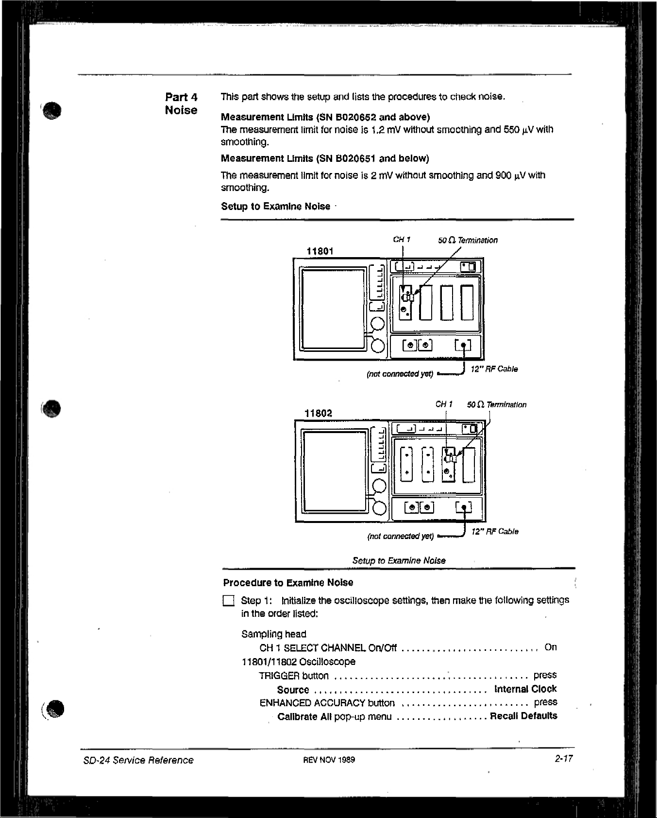
4
Noise
This
part
shows
Measurement
The
measurement limit
smoothing.
Measurement
The
measurement limit
smoothing.
Setup to
Limits
Limits
Examine Noise
the
setup
and
lists
the
procedurestocheck noise.
(SN
5020652
for
noiseis1.2mywithout smoothing
(SN
8020651
for
noiseis2
11801
and
and
my
r-~
IC-L~-~/
I
I ~Jl
I
above)
below)
wWioUt
CM
I
L~i
L~
~U~
c~
~
(not
connected
yet)
smoothing
50(1
Termination
/
I~l
U
Lq~J
J
12”RFC~b!e
and 550
and
900~Vwith
jiV
with
ProceduretoExamine Noise
Li
Step1:Initialize
in
the
order
Sampling
11801/11802
head
Cl-Il
SELECT
TRIGGER
Source
ENHANCED ACCURACY
Calibrate
the
oscilloscope
listed:
CHANNEL
Oscilloscope
button
All
pop-up
Setup
On/Off
button
menu
to
Examine
settings,
CH150(1
Noise
then
make
7brmlnatlon
12”RFC2bIe
the
following
Internal
Recall
settings
On
press
Clock
press
Defaults
SD-24
Service
Reference
REV
NOV
1989
2-17
Page 19

Part4Noise
C
Step
2:
Touch
Loop
Gain
in
the ENHANCED
--—.-..-......-.-....i
ACCURACY
major
menu.
*
0
Step3:DIsconnect
the
CALIBRATORtotheCH1
C
Step4:Touch
then
Proceedinthe
C
Step5:DIsconnect
50
atemllnatiorl,
C
Step6:Press
C
Step7:Set
C
Step
8:
Press
C
Step9:Touch
set
the
Veil
Size:Mlto2mV/div.
[I]
Step
10:
Touch
C
Step
11:Inthe
selectorsInthe
•
Mainframe
.1
the
5011termination
the channel
Loop
the
CALIBRATOR
the
WAVEFORM
AverageNto
the
AUTOSET
the
vertical Icon.
DefWaat
Vertical
order
DescrIptIon
given:
Input
through
number
Gain
On.
the topofthe
you
Calibration
button,
button.
If
the
Veil
pop-up
from
the
the12inchRFcable.
are
from
theCH1
and
Size:Mlis
screen.
Cli1Input
using,
Automatic
pop-up
then touch
menu.
input
menu, touch
and
Calibrate,
and
Acquire
notat2
the
following
connect
and
reconnect
Desc.
mV/div,
then
the
•
•Avg(
•
Mainframe
.1
(
.)
•
Enter Desc
C
Step
12:
Press
the
C
Step
the
C
Step
C
Step
[J
Step
C
Step
Sampling
C
Step
C
Step
C
Step
13:
Touch
MEASURE
14:
15:
major
Set
Data
Examine
Examine that
16:
Press
17:
Touch
Head
18:
Press
19:.Examine
Examine
20:
Repeat
MEASURE
RMSInthe
menu.
Intervaltowhole
that
RMSis1.2
RMSis2
the
WAVEFORM
Sampling
Functions
the
MEASURE
that
the
that
the
steps
2 through19for
button,
Measurements
Head
pop-up
button,
RMSIs550
RMS
and
zoneinthe RMS pop-up
my.
(SN
my.
(SN
button.
Fnc’s,
is
and
menu.
~V.
900
channel
then touch
pop-up
B020652
8020651
then
set
(SN
B020652
~V,
(SN
B010651
2.
Measurements.
menu,
and
then
RMS
menu.
and
above)
and
below)
SmoothingtoOnInthe
and
above)
and
below).
In
2-18
REV
NOV1989
Checks and
Adjustments
Page 20

Checks
and
Ad/usfments
Rise
lime
This
part
shows
the
Specifications
The
specification
Setup
to
setup
for
the
Rise
and
sampling
lime
lists
the
proceduretocheck the
head
rise
timeis17.5
pa.
rise
time.
Calibration
Generator
Stop
Calibration
Generator
remote
head
Step
Calibration
Generator
Calibration
Generator
Step
Step
power
supply
SD-24
Seivlce
Reference
Manual
ProceduretoCheck
Step1:InitIalize
in the
order
listed:
Sampling
head
CH1SELECT
Setup
Rise
Time
the
oscilloscope
CHANNEL
to
Check
settings,
On/Off
Rise
Time
then
make
the
following
On
Page 21

Checks
Part
5
arid
Adjustments
Rise
Time
11801/11802
ENHANCED
i
TRIGGER
Calibration step
ON/STANDBY
C
Step2:Press
~
Step3:Press
O
Step4:Touch
with the
C
Step5:Touch
O
Step6:Set
Li
Step
7:
C
Step8:Touch
Li
Step9:Touch
Res
pop-up
Li
Step
10:
Oscilloscope
ACCURACY
Calibrate All
button
Source
generator
switch
the
AUTOSET
the
WAVEFORM
Main
top
knob.
Acquire DescInthe
AverageNto
Set
AverageNto
the horizontal
Main
menu.
Press
the
button
pop-up
Record
Pos
MEASURE
menu
button.
button,
Length,afld
On,
and
128
wIth
icon,
and
then SettoMlninthe
button.
and
then
then
set
WAVEFORM
then touch
the
top
and
then
Set
knob.
set the Main
touch
Main
major
Avg
Numeric
Recall
Horizontal
Record
menu.
N.
Defaults
Internal
Len to
Size
to
100
Entry&Knob
press
(.!.~.1
press
Clock
ON
Desc.
5120
na/div.
O
~
C
C
O
O
Li
C
C
O
~
Step
11:
menu.
Step
12:
Off
in
the
Step
13:
Step
14:
Step
15:
Step
16:
pulse
10
Step
17:
stepisat
Step
18:
Step
19:
screen.
Step
20:
Step
21:
Touch
Measurements
Touch
Rise
Rise
pop-up
Set
the Main
Touch
BaselineInthe
Touchablank
Set
the
Baseline
ns
before
Touch
the
Set
Set
Touch
Record
the
the horizontal
left-most
the
Main
the Main
Riseinthe
the
inthe
MEASURE
menu.
SizetoS
portionofthe
(bottom
step.
icon, and
edgeofthe
Sizeto20
Possothat
MEASURE
Mean:
valueinthe
and
then
major
ns/div,
Rise
pop-up
screentoexit
knob)tothe
screen.
ps/div.
the
major
RiseInthe
menu,
menu.
then
set
stepisapproximately
menu.
Rise
pop-up
Measurements
and
then
set
this
menu.
averageofthe bottomofthe
the Main
Possothat
menu
tar
centeredonthe
pop-up
Wacklng
the
later
usa
(
to
2-20
REV
JUN
1959
SD-24
Service
Reference Manual
Page 22

Li
Step
22:
sampling
rise
time
Note
that
generator.
O
Step
23:
Calculate
head—J(Mean
—
Calibration
Check
Step
that
the
sampling
:
value)
Generation
the
sampling head
head
rise
time
with
2
-
(Calibration
riseisread from
rise
timeis17.5
the
following
Step
Generator
the
calibration
Pan
ps.
5
Rise
formula:
rise)2
step
Time
C
Step
24:
Repeat
steps
2 through23for
channel
2.
0
SD-24
Service
Reference
REV
NOV
1989
2-21
Page 23

Part
6
Acquisition
Aberrations
This
part
shows
aberrations.
the
setup
and
lists
the
procedurestocheck
Checks
and
acquisition
Adjustments
(
S
Measurement
The
measurement limits
Aberrations
Time
Difference from
Rising
Oto300ps
300psto5ns
5
100nsand
EdgeofWaveform
nato
Limits
Specifications.
100
ns
up
—lonsto—2Ops
for acquisition
Tabie
2-3
—
the
aberrations
Aberrations
Minimum
—7%
—4%
Specification
aberration%12%
C
aberration %
are
listedinThbIe
Specifications
-1.2%aberration %
-0.6%
aberration %
—4%aberration %
2-3,
4%
<1.2%
O,6%
~%
(
2-22
REV
JUN
1989
SD-24
Setv/ce
Reference
(c
Manual
Page 24

Checks
Part6Acquisition
~nd
Adjustments
Aberrations
S
SetuptoExamine
11801
11802
Acquisition
Calibration
Generator
remote
Step
head
Calibration
remote
Aberrations
Step
Generator
head
Cailbrat
Ion
Generator
Calibration
Generator
Step
power
supply
Step
power
supply
S
Procedure to
Li
Step1:Initialize
in
the
order
Sampling
CH1
11801/11802
ENHANCED
Calibrate
TRIGGER
Source
Calibration
ON/STANDBY
SetuptoExamine
Examine
tile
listed:
head
SELECT
CHANNEL
OscIlloscope
ACCURACY
All
button
step
generator
Acquls
Won
oscilloscope
pop-up
switch
Acquisition
Aberrations
settings,
On/Off
Aberrations
then
make
the
following
settings
On
button press
menu
Recall
Defaults
press
Internal
Clock
OF’1
St~24
Se,vice
Reference
Manual
Li
Step2:Press
the
WAVEFORM
REV
JUN
1989
button,
and
then
touch AcquIre Desc.
2-23
Page 25

Checks
Part
and
6 Acquisition
Adjustments
Aberrations
fl
Step
3:
Set
AverageNto
On, and
then
touch Set
Avg
N,
S
Li
Step4:Set
E
Step
5: Press
fl
Step6:Touch
fl
Step
7:
left-most
Li
Step8:Touch
averageofthe
the screenisat
0
Step9:Set
Li
Step
10:
Res
pop-up
~
Step
11:
from
100 ns
centerline.
Li
Step
12:
aberration
horizontal centerline (0.6%ofthe
Li
Step
13:
AverageNto
the
AUTOSET
the horizontal
Set
the
Main
edgeofthe
the
Touch
menu.
Set
after
Examine
occurrIng1OOns
Toucfl
screen.
the
vertical
topofthe
the horizontal
Vert
Size:Mlto2mV/div.
Veil
Offset:Mland
Veil
Offset:Mlso
the
step
that
the horizontal
128
wIth
button.
icon, and
P05sothat
icon,
and
pulse
from
centerline.
to
the
right
The
magnitudeofthe
after
the
step
Icon,
the top
the
100
that
stepis0.75
knob,
then
set
rising
edgeofthe
then
set
the
ns
after
then Fineinthe
the averageofthe
edgeofthe
maximum
amplitude).
and
then
set
the Main
Veil
the
screenIsat
vertical
the MaIn
Size
stepisat
Oftset:M1sothat
step
to
Numeric
topofthe
positive
divisions
to 100
na/div.
the
the
the
right
edge
of
Entry&Knob
pulse
the
horizontal
and
negative
from
the
Sizetoions/div.
Li
Step
ieft-rnost
fl
Step
aberration
from
Li
Step
rising
Li
Step
aberration
from
~
Step
~
Step
Li
Step
from
centerline.
fl
Step
Li
Step
left-most
14:
Set
the
Main
Possothat
edge
of
the
screen.
15:
Examine
occurring
the
horizontal centerline (1.2%ofthe
16:
Set
eageofThe
17:
Examine
occurrIng
the
horizontal centerline
18:
Touch
19:
Touch
20:
Set
100 ns
21:
Touch
22:
Set
edgeofthe
that
5 ns
the
Main
stepisat
that
300
the horizontal
the
vertical
the
yen
Offset:M1sothat
after
the
steptothe
the
horizontal
the
Main Possothat
screen,
The
magnitudeofthe
to
100
ns
Sizeto500
the
left-most
the
magnitudeofthe
ps
toans after
(4-0%ofthe
icon, and
icon,
right
icon,
the rising
after
the
step
ps/div
edgeofthe
the
then
and
then
the averageofthe topofthe
edgeofthe
and
then
the
rising
edgeofthe
maximum
stepisi
amplitude).
and
then
maximum
stepis5.O
step
amplitude).
set
the Main
set
the
screenisat
set
the Main
edgeofthe
stepisat
positive
5
vertical
the Main
screen.
positive
vertical
Veil
Slze:M1to10
stepIsat
the
and
divisions
Possothat
and
divisions
Size
to
500
the
horizontal
Sizeto50
the
(
negative
the
negative
ns/div.
mV/div.
pulse
pa.
S
2-24
REV
JUN
1989
SD-24
Sen’ice
Reference
Manual
Page 26
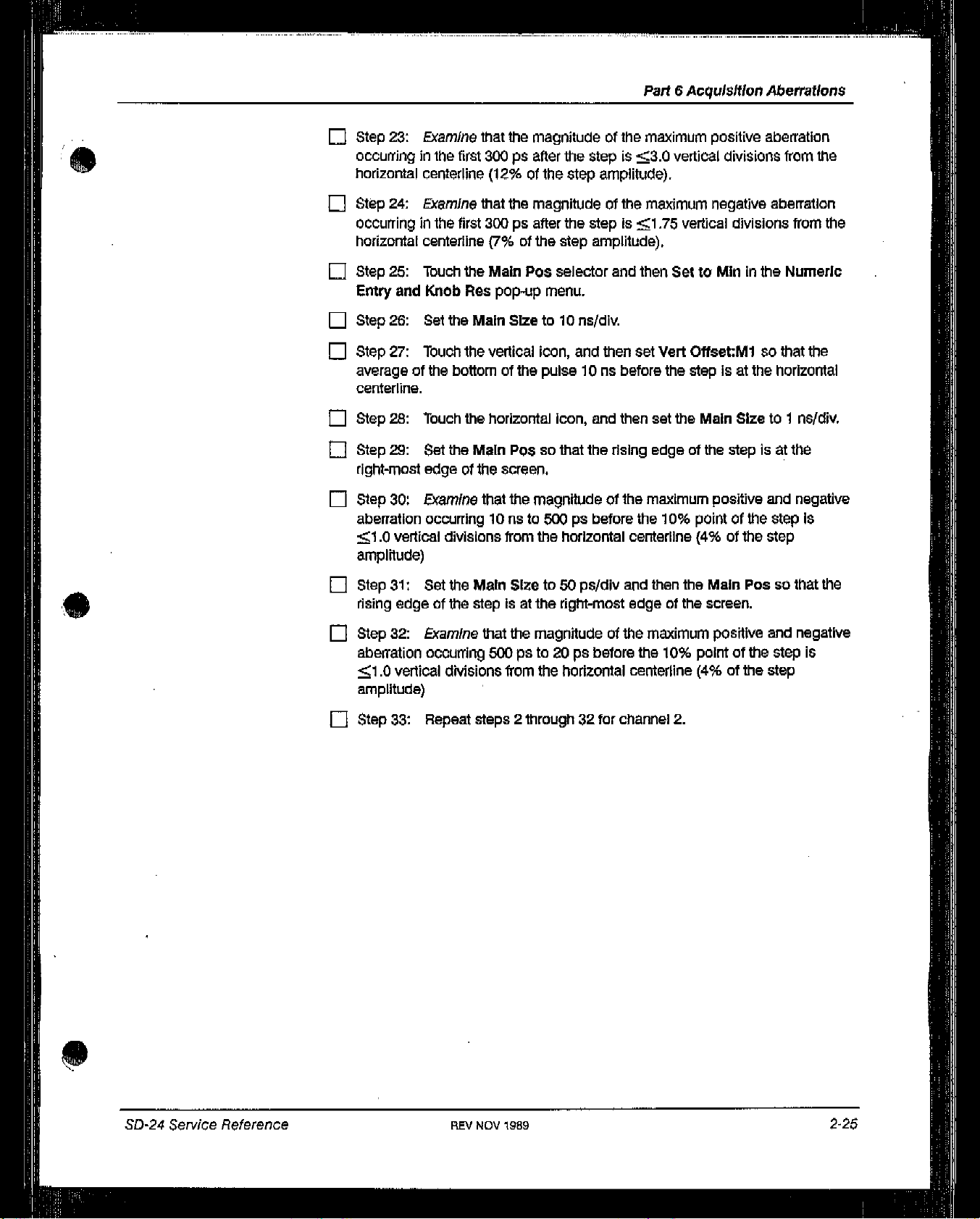
Li
Step
23:
Examine
occurringinthe
horizontal centerline
Li
Step
24:
ExamIne
occurringinthe
horizontal centerline
Li
Step
25:
Thuch
Entry
and
Knob
Li
Step
26:
Set
Step
27:
28:
29:
30:
Touch
Touch
Set
edgeofthe
Examine
occurring
Li
averageofthe
centerline.
Li
Step
Step
Li
right-most
El
Step
aberration
1.0vertIcal
amplitude)
that
the
first
300
ps
(12%ofthe
that
the
first
300
pa
(7%ofthe
the
Main Pos
Res
pop-up
the
Main
Sizeto10
the
vertical
bottomofThe
the horizontal
the
Main
P03sothat
screen.
that
the
iOnsto500pabefore
divisions
from
Part6AcquIsitionAberrations
magnitudeofthe
after
the
stepis3.0
step
amplitude).
magnitudeofthe
after
the
stepIsi
step
amplitude),
selector
menu.
na/div.
icon, and
pulse10ns
icon, and
the
magnitudeofthe
the horIzontal centerline (4%ofthe
maximum
vertical
maximum negative
.75
vertical
and
then SettoMmInthe
Then
set
Veil
Offset:M1 so
before
then
rising
the
set
the Main
edgeofthe
maximum
the
10%
stepisat
pointofthe
positive
divisions from
divisions
Sizeto1
stepIsat
positive
aberratIon
the
aberration
from
the
Numeric
that
the
the horizontal
ne/div.
the
and
negative
step
is
step
E
Step
rising
Step
Li
aberration
1
amplitude)
El
Step
31:
Set
edgeofthe
32:
Examine
occuning
.0
verticai
Repeat
33:
the MaIn
stepIsat
that
500
dMsions
steps
Sizeto50
the
the
magnitudeofthe
psto20ps
from
2 through32for
ps/div
right-most
the horizontal
and
edgeofthe
before
centerline
channel
then
the
maximum
the
10%
2.
MaIn Possothat
screen.
positive
pointofthe
(4%ofthe
and
step
step
the
negative
is
0
SD-24
Service
Reference
RE~
NOV
1989
2-25
Page 27

Coincidence
Between
Channels
This
part
shows
between
channels.
Specifications
The
specification
the
for
setup
and
the
coincidence
lists
the
procedurestocheck
between
channels
is
Checks
and
the
coincidence
lOps,
Adjustments
SetuptoCheck
CoIncidence
Calibration
E~ønørato,
Between
Step
Calibration
Generator
Step
Channels
Calibration
Generator
Calibration
Generator
Step
Step
ProceduretoCheck
Li
Step1:initialize
in
the
order
listed:
Sampling
head
CH1SELECT
Check
Coincidence
Coincidence Between
the
oscIlloscope
CHANNEL
settings,
On/Ott
Between
Channels
Channels
then
make
~SD-24
Service
the
following
Reference
On
Manual
Page 28

Checks
Part7CoIncidence Between
and
Adjustments
Channels
S
11801/11802
ENHANCED
TRIGGER
Calibration step
ON/STANDBY
~
Step
2:
E
Step
3:
LI Step
LI Step
LI
~
Eli
4:
with
the
5:
Step
6:
Step
7:
Step
8:
connect
button.
Osculoscope
ACCURACY
Calibrate All
button
Source
Press
Press
Touch
top
knob.
Touch
Set
AverageNto
Set
AverageNto64with the
Disconnect
it
to
OH2,and
pop-up
generator
switch
the
AUTOSET
the
WAVEFORM
Main
Record
Acquire
Descinthe
the
calibration
then
button
menu
button.
button,
Length,
On,
and
press
and
then
and
then
WAVEFORM
then
touch
top
knob.
step
generator
the
CR2SELECT
touch
set
major
Set
Main
Avg
remote
Recall
Internal
Horizontal
Record
menu.
N.
head
fromOH1,
CHANNEL
On/Off
press
Defaults
press
Clock
ON
Desc.
Len to
1024
~
Step
9:
LI
Step
10:
~
Step
ii:
Acquire
LI
Step
12:
fl
Step
13:
screen.
~
Step
14:
LI
Step
lb:
LI Step
LI Step
~
LI Step
fl
16:
17:
Step
18:
connectittoCH1,
button.
19:
Step
20:
pop-up
Press
AUTOSEt
Select
the
Touch
Acquire
Description
Touch
Exit,
Set
the Main
Press
the
STORE/RECALL
Touch
Trace 2inthe
Touch
Recall
Touch
STOIin
Disconnect
and
Press
the
TouCh
Measurements
menu.
horizontal
pop-up
Possothat
TraceInthe
the
then
MEASURE
Icon,
Desc,
menu.
Store
the
Recall
calibration
press
button.
and
tnen
set
and
then
set
AverageNtoOnIn
the
stepisapproximately
button.
Trace
pop-up
STORE/RECALL
Stored
step
theCR1
and
then
Trace
generator
SELECT
Prop
the Main
menu.
pop-up
Delayinthe
Sizeto10
major
remote head
CHANNEL
ps/div.
the
centeredonthe
menu.
menu.
tram
CR2,
On/Off
Measurements
0
50-24
Service
Reference
~
LI Step
Manual
Step
ri
the
21:
Prop
22:
Touch
Delay
Check
REV
Prop
pop-up
that
the
JUN
Delayinthe
menu.
magnitudeofthe
1989
MEASURE
major menu and
Prop
then
Delayis10p5.
Trace
2-27
3
Page 29

Maximum
Signal
Voltage
This
part
voltage.
shows
the
setup
and
lists
the procedure
Checks and
to examine
the
maximum
Adjustments
s~gna~
Trigger
Input
Measurement
The
measurement
amplitude.
Limit
limit
SetuptoExamine
for the
Maximum
maximum
Signal
Voltage
LJa]
signal
_i
voltage
~ULL
50C~Coaxial
Cable
is1%of
Positive Output
th~
f6si
step
Tugger
Ou~.ut
Rise
Trigger
Input
Setup
to
Examine
50
fl
Coaxial
Maximum
Cable
Signal
SD-24
Po~ith~e
Service
Fast
Rise
Output
A~lerence
Manual
Page 30

Checks
PartBMaximum
and
Adjustments
Signal
Voltage
S
ProceduretoExamine Maximum
LI Step
fl
LI
1:
nitialize
In
the
order
Sampling
11801/11802
Calibration
Step2:Touch
waveformisvertically
Step3:Set
peak-to-peak
head
OH1SELECT
ENHANCED ACCURACY
Calibrate All
TRIGGER
Slope
MaIn
Size
Amplitude
Period
Var
adjustment
the
oscilloscope
listed:
CHANNEL
OscIlloscope
pop-up
button
generator
the
vertical
the
calibration generator’s amplitude so
square wave.
On/Ott..
button
menu
Icon,
centered on
Signal
settings,
and
the
Voltage
then
then
set
screen.
the
make
the
following
Recall
maximum
Vert
Offset:Mlso
thatitdisplaysa1
settings
On
press
Defaults
press
-
5
~s/dlv
amplitude
lOILs
mid
range
that
V
the
LI Step
LI
LI Step
LI
LI Step
LI Step
LI
fl
~
LI Step
LI Step
4:
Step5:Set
left-most
6:
Step7:Touch
Description
8:
9:
averageofthe
centerline.
Step
10:
Step
11:
Res pop-up
Step
12:
ns
after
13:
14:
aberration
vertical
Touch
the
horizontal
the
Main Possothat
edgeofthe screen
Press
the
WAVEFORM
Acquire
pop-up
Touch
Set
Touch
the
topofthe
Set
Vert
Touch
Veil
menu.
Set
Veil
the
stepison
Set
the Main
Examine
from
200 nsto800
divisions uom
Deso,
menu.
Avg
N,and
vertical
pulse
Slze:M1to5
OffsetMland
Offset:Mlso
the horizontal
Sizeto200
that
the
the
icon,
and then
the
(within
icon, and
magnitudeofthe
horizontal centerline(1%ofthe
1/2
button.
and
then
then
set
then
500nsafter
mV/div.
that
centerline.
ns/div.
ns from
set
the
Main
positive-going
division).
set
AverageNtoOnin
AverageNto
set
the
the
then
Fineinthe
the
averageofthe topofthe
the
maximum
rising
step
128
Veil
stepison
Offset:Mlso
Numeric
edgeofthe
positive
Sizeto500
is
near
with the
the horizontal
stepis2
step
ns/div.
the
the
Acquire
tO~
knob.
that
Entry&Knob
pulse
and negative
amplitude).
the
500
50-24
Service
Reference
Manual
fl
Step
15:
Touch
the horizontal
REV
JUN 1989
icon, and
then
set
the
Main
Sizeto20
ns/div.
2-29
Page 31
Checks
Pail
and
B
Maximum
Adjustments
Signal
Voltage
E
Step
16:
Set
screen
E
Step
abelTation from10ns
divisions
E
Step
(within
17:
18:
Examine
torn
Repeat
the
Main
Possothat
1/2
division)
that
the
magnitudeofthe
to 200
the horizontal centerline (1%ofthe
allofPart8forCH2.
ns from
the
stepisnear
the
rising
maximum
edgeofthe
the
left-most
positive
step
amplitude).
edgeofthe
and negative
stepis2
(
vertical
S.
2-30
REV
JUN
1989
SD-24
Service
Reference
C
Manual
Page 32

Checks
and
Adjustments
Isolation Between
Channels
This
part
shows
channels.
Specifications
The
measurement
the
setup
limit
for
and
lists
the
procedurestocheck
the
isolation between
channels
the
is
isolation
bet’Neen
Sofl
Termination
SetuptoCheck
Isolation
Calibration
Generator
Between
Step
Calibration
Generator
Channels
Step
Calibration
Genecator
£fep
power
wpply
SD-24
Se,vic~
Peference
ProceduretoCheck
Step1:Initialize
in
the
Sampling
Manual
Isolation
the
order
listed:
head
C111SELECT
check
Between
oscilloscope
CHANNEL
On/Off
Isolation
Channels
settings,
Between
then
Channels
the
following
settings
On
Page 33

Checks
Pail9Isolation Between
and
Adjus~nent~
Channels
11801/11802
ENHANCED ACCURACY
TRIGGER
Calibration step
ON/STANDBY
[]
Step2:Press
~
Step3:Touch
~
Step4:Press
~
Step5:•lbuch
with
the top
~
Step6:Touch
El
Step7:Set
Description
~
Step8:Set
[I]
Step9:Press
OscIlloscope
button
Calibrate
Source
All
pop-up
button press
generator
Switch
the
AUTOSET
the horizontal
the
WAVEFORM
Main
Record
knob.
AcquIre DescInthe
AverageNto
pop-up
AverageNto
menu.
theCH2
menu
button.
icon, and
button,
Len9th,
On,
and
1024
with
SELECT
......,.....,..
then
set
and
then
and
then
WAVEPORM
then
touch
the
top
CHANNEL
buttononthe
the
touch
set
major
Set
knob.
Recall
Internal
Main
Sizeto200
Horizontal
Main
Record
menu.
AvgNIn
sampling
the
press
Defaults
Clock
ON
ps/dIv.
DeSc.
Len to
Acquire
head.
(
1024
~
Step
10:
Touch
~
Step
11:
Touch
AverageNto
~
Step
12:
Wait
menu
shows
that
~
Step
13:
Touch
~
Step
14:
TOuch
pop-up
~
Step
El
Step
Li]
Step
pop-up
~
Step
LI Step
E
Step
and
OH2,connect the50(~
SELECT
menu,
15:
Record
16:
PresstheCH1SELECTCHANNEL
17:
Touch
menu.
18:
Record
19:
Check
20:
Disconnect the
the50fl
CHANNEL
the
vertical
Acquire
On.
until
1024
the
Measurements
theOH2
Measurements
theOH1
that
termination
Descinthe
the
Acquire
averages
MEASURE
(CH2Peak-Peak/OH1Peak-Peak)x100%
calibration
fromCH2.
terminationtoOH1,and
On/Off button,
icon, and
Peak-Peak
Peak-Peak
then
WAVEFORM
Dasc
selectorinthe
have
been
button.
and
then
and
then
step
Connect
set the
Peak-PeakInthe
measurement
Peak-Peakinthe
measurement
generator
Vert
major
WAVEFORM
completed.
for
button.
for
remote
the calibration
then
Size:M2to2mV/div.
menu,
and
then
set
major
Measurements
later
use.
Measurements
later
use.
1
%.
head
fromOH1
step
generator to
press
theCH2
(
S
2-32
~
Step
21:
Press
the
AUTOSET
~
Step
22:
TouCh
the horizontal
REV
JUN
~989
button.
icon,
and
then
S~-24
set
the
Main
Sen//ce
Sizeto200
Reference
Manual
pS/div.
Page 34

El
Step
23:
Press
the
Cl-I1SELECT
Part
9
IsolatIonBetween
CHANNEL button.
Channels
S ~
El
El
El
[J
El
D
Q
El
Step
24:
Step
25:
Step
26:
menu
shows
Step
27:
Step
28:
pop-up
Step
29:
Step
30:
Step
31: Record
Step
32:
Press
the
AUTOSE~
Press WAVEFORM
Wait
until
the Acquire
that
1024
averages
Press
the
MEASURE
Touch
Measurements
menu.
Record
Press
Checkthat
theCH1
the
Cl-I2SELECT
theOH2
(CM1Peak-Peak/0H2
button.
button.
Desc
selectorinthe
have
been
button.
and
then
Peak-Peak
CHANNEL button.
Peak-Peak
WAVEFORM
completed.
Peak-Peakinthe
measurement
measurement
Peak-Peak)
for
for
major
Measurements
later
use,
later
use.
x 100%
1%.
S
SD-24
Serv/ce
Reference
SEV
NOV
1989
2-33
Page 35

Checks
and
Adjustments
S
S
Output
Part 10
Amplitude
This
part
shows
Specifications
The
specification
SetuptoCheck
the
setup
for
the
Output
11801
11802
and
lists
output
amplitudeis250my±5
Amplitude
L~l~jL
p.
b[~m
rji
I
I
-‘I
I
-fl
L~
L~)
the
procedurestocheck the
CH
I
I
Lc1~/
IC—sJ-~-~-H
CH
sOC
/
~-
1
Tennination
irn;
my.
son
Toimination
output
amplitude.
C.
S
ProceduretoCheck
El
Step1:Initialize
in
the
order
listed:
Sampling
11801/11802
El
Step2:Press
El
Step3:Set
head
CM1SELECT
Oscilloscope
ENHANCED ACCURACY
Calibrate
TRIGGER
button
Source
the
AverageNto
~
..b
Setup to
Output
the
oscilloscope
CHANNEL
All
pop-up
WAVEFORM
Check
AmplItude
On/Off..
button
menu
On,
~:
[a~J~j
Output
settings,
. -
. . -
button,
and
and
then
Amplitude
then
then
touch
make
touch
Set
the
Acquire
Avg
foilowing
Recall
Internal
N
settings
On
press
Detaults
press
Clock
Desc.
C
2-34
REV
JUN
1989
SD-24
Sen//ce
Reference
Manual
Page 36

El
Step4:Set
AverageNto64with the
top
Past10Output
knob.
Amplit
ude
S
El
Step5:Touch
then
set
El
Step6:Press
El
Step
7:
El
Step8:Touch
El
Step9:Press
Amplitude.
El
Step
10:
Amplitude
El
Step
11:
o
Step
12:
El
Step
13:
El
Step
14:
El
Step
15:
step.
o
Step
16:
Sampling
the
Clii
TDRtoOn.
the
AUTOSET
Touch
the
Main
the
Touch
Automatic
pop-up
Touch
Cursorsatthe topofthe
Touch
Cursor
Touch
Exit to
Set
Cursor1(top knob) to
Set
Cursor2to
CheckthatAVls2sOmV±5mV,
Head Fnc’sinthe
button.
horizontal
Pos
ENHANCED ACCURACY
menu.
Icon,
and
Calibrate
Type
exit
this
the
thenMmIn
and
and
and
then
menu.
the averageofthe baseofthe
averageofthe
WAVEFORM
then
set
the
Main
Pos
button,
then
Proceedinthe
screen.
HorIzontal
topofthe
Main
pop-up
and
then touch
Bars.
pulse
major
Size
menu.
100
menu,
to
100
TDR
TDR
ns
and
ns/dlv,
pulse.
after
the
(5
El
D
o
El
El
~
0
El
El
Step
17:
Press
Step
18:
Touch
in
the
SamplIng
Step
19:
Touch
Step
20:
Touch
is
centeredonthe
Step
21:
Touch
Step
22:
Set
Step
23:
Set
step.
Step
24:
Check
Step
25:
Repeat
the
WAVEFORM
Sampling
Head
Functions
Exit to
exit
the
vertical icon
screen.
Cursorsatthe
Cursor1(top knob) to
Cursor2to
that
.SVis-250mV±5
all
of Part10forCH2.
button.
Head
Fnc’s,
pop-up
this
menu.
and
tO~ofthe
the
averageofthe topofthe
and
then
set
the
TDR
Polarity
menu.
set
the
Veil
Offset;Mlso
screen.
the averageofthe baseofthe
pulse
my.
that
100 ns
to
the
step
pulse.
after
—
the
0
5D-24
Serv/ce
Reference
REV
NOV1989
2-35
Page 37

Part
ii
TDR Aberrations
This
part
shows
Specifications
The
specifications
Specifications,
the
setup
for
TDR
and
lists
the
procedurestocheck the
aberrations
Table
2-4—Aberrations Specificat/ons
are
listedinTable
Checks
and
Adjustments
TOR
aberrat%ons.
2-4, Aberrations
(.
S
Time Difference
the Rising
Edge
Waveform
Oto300ps
Soopstosns
5 ns
and
up
-ionsto—20
Ps
from
of
Minimum
Specification
.
-3%aberration%
0%
‘—1%abeiTation
96
±1%
—3%aberration
%
3%
Measurement
—5%
aberration
i
5%
Limit
%
(
.4
S
REV
JUN
2-36
1989
SD-24
Serv/ce
Reference
Manual
Page 38

Part
Checks
11
TDR
and
Adjustments
Aberrations
(5
Setup to
Check
TDR
Aberrations
11801
CM
I
LJ~/
[L~I~J
50
/
L
CM
1
~I
Termination
~i
L
L!J1
50
(~
Terrni,,e.rlon
ProceduretoCheck
i:i~
Step1:InitIalize
in
the
order
listed:
Sampling
11801/11802
Step
El
Step
El
Step
El
Step
El
then
head
CH1
SELECT
Oscilloscope
ENHANCED ACCURACY
Calibrate
TRIGGER
2:
3:
4:
5:
set
button
Source
Press
Set
AverageNto
Set
AverageNto
Touch
theCM1
the
Sampling
Setup to
TDR
Aberrations
the
oscilloscope
CHANNEL
All
pop-up
WAVEFORM
TDRtoOninthe
Check
On/Off
button
menu
On,
128
Head
button,
and
with the top
Fnc’sinthe
TOR
Aberrations
settings,
then
Sampling
..
and
touch Set
then
then
knob.
make
the
following
•..........
Recall
Internal
touch
Acquire
Avg
N.
WAVEFORM
Head
major
Functions
settings
press
Defaults
press
Clock
Desc.
menu,
pop-up
On
and
menu.
SD-24
Service
Reference Manual
Step
El
Amplitude.
6:
Press
REV
the
ENHANCED
JUN
1989
ACCURACY
button,
and
then
tOuch
TDR
2-37
Page 39

Part
11
rDR
Aberrations
Li
Step7:Touch
Amplitude
Li
Step
8:
Li
Step
9:
Li
Step
10:
left-most
Step
11:
averageofthe
centerline,
fl
Step
12:
Li
Step
13:
Res
pop-up
Li
Step
14:
100nsafter
Li
Step
15:
Automatic
pop-up
Press
Touch
Set
edgeOtthe
Touch
Set
Touch
Set
Touch
menu.
vie
AUTOSET
the
the Main
the
topofthe
the
Veil
yen
menu.
Veil
the
stepIsat
the horizontal
Calibrate
button.
horizontal
screen.
vertical
Size:Mlto2mV/div.
Offset:Mland
Offset:Mlso
icon,
Possothat
icon,
pulse
the horizontal
and
and
the rising
anø
100nsafter
then
that
icon,
and
then
Proceedinthe
then set
then
the averageofthe
centerline.
then
the Main
edgeofthe
set
the
the
stepisat
Fine in
set
the Main
Veil
the
Numeric
TDR
Sizeto100
stepisat
Offset:M1 so
the
topofthe
Sizeto10
the
horizontal
Entry&Knob
pulse
na/div.
that
the
ns/dlv.
aberration
Li
Step
16:
left-most
Li
Step
17:
1
.25
amplitude).
Li
Step
18:
the
rising
Li
Step
19:
aberration
from
the horizontal centerline (3%ofthe
Li
Step
20:
Li
Step
21:
Li
Step
22:
100nsafter
Li
Step
Li
Step
left-most
Li
Step
occurringinthe
divisions
Set
edgeofthe
Check
occurring
vertical
Set
edgeofthe
Check
occurring
Touch
Touch
Set
23:
Touch
24:
Set
edgeofthe
25:
Examine
from
the
Main
Possothat
screen.
that
the
magnitudeofthe
5 ns
after
the
steptothe
dMsions
the
the horizontal
the
the
the
stepisat
the
the Main
fIrst 300psafter
the horizontai centerline
from
Main
Sizeto500
stepIsat
that
the
magnitudeofthe
300psto5ns
vertical
Veil
horizontal
screen.
that
icon,
Offset:M1sothat
the horizontal
Possothat
the
magnitudeotthe
the
horizontal centerline
the
icon, and
and
icon, and
the
the
rising
edgeofthe
maximum
right
ps/div
7
and
left-most
alter
the
90%
edgeofthe
maximum
the
stepis3.75
step
amplitude).
then
set
then
set
the averageofthe topofthe
centerline.
then
set
rising
edgeofthe
maxImum
pointofthe
(15%ofthe
positive
edgeofthe
(1%ofthe
then
set
positive
the
Main
the
Veil
the Main
stepis3.75
step
the Main
Slze:M1to10
positive
amplitude).
stepl~at
and
screen
screen.
and
vertical
Sizeto500
Sizeto50
stepisat
aberration
the
negative
is
step
Possothat
negative
divisions
ne/div.
mV/div.
pulse
ps/div.
the’
vertical
2-38
REV
JUN 1989
Checks
and
Adjustments
Page 40

Step
26:
occurringinthe
divisions
E
Step
27:
E
Step
28:
Entry
D
Step
29:
average
centerline.
fl
Step
30:
Step
31:
ExamIne
from
Set
Touch
and
Touch
of
Touch
Set
that
the
first
300PSafter
the
horizontal
The
Main
Sizeto2
the Main
Knob
Flea
the
tne
bottomofthe
the horizontal
the Main P0350that
Pos
pop-up
vertical
magnitudeofthe
the
90%
pointofthe
centerline
selector
menu.
icon, and
pulse10ns
icon, and
(5%ofthe
ns/cliv,
and
then
the
rising
before
then
Part•11
maximum
stepIs1
step
then
SettoMmInthe
set
yen
Oflset:M1sothat
the
stepisat
set the Main
edgeofthe
TDR
Aberrations
negative
amplitude).
aberration
.25
the horizontal
Sizeto1
stepisat
vertical
Numeric
the
ns/div.
the
right-most
E
Step
aberration
vertical
D
Step
rising
[~
Step
aberration
vertical
C)
Step
C)
Step
the
C)
Step
edgeofThe
32:
Check
occurring
dMsions
33:
Set
edgeofthe
34:
Check
occurring
dMsions
35:
Press
36:
Touch
Sampling
37:
Repeat
that
the
iOns
from
the horizontal centerline
the
Main
stepisat
that
the
500pato20ps
from
the horizontal centerline
the
WAVEFORM
Sampling
Head
Functions
Steps 2
screen.
magnitudeofThe
to 500psbetore
Sizeto50
the
magnitudeofthe
Head
Through
ps/div
right-most
button.
Fnc’s,
pop-up
36.
and
edgeofthe
before
and
menu.
maximum
the
10%
pointofthe
(4%ofthe
then
the Main
maximum
the
10%
poIntofthe
(4%ofthe
then
set
positive
screen.
positive
the
and
step
amplitude).
Possothat
and
step ampiitude)
TDR
Polarity
negative
stepis1
the
negative
stepis~1
to-in
.0
.0
S
SD-24
Sesv!ce
Reference
REV
NOV
1989
2-39
Page 41

Reflected
Rise
Part
Time
12
This
part
shows
time.
Specifications
The
specification
the
for
setup
the
reflected
and lists
the
procedures.tocheck
rise
timeis35
ps.
Checks
the
reflected
and
Adjustments
rise
(.
6~
Precision
Precision
r
Precision
Semi-Rigid Cable
Short
C(rcuit
Semi-Rigid Cable
SetuptoCheck
Termination
Reflected
Rise
Time
CM
I
CH
I
(
2-40
Precision
She,1
Chcuit
Thm,ination
ProceduretoCheck Reflected
C)
Step1:initialize the
in
the
order
listed:
Sampling
11801/11802
head
CH1SELECT
Oscilloscope
ENHANCED
ACCURACY
Calibrate
TRIGGER
button
CHANNEL
All
Source
REV
JUN 1980
SetuptoCheck
Rise
lime
oscilloscope
On/Off
button
pop-up
menu
Reflected
settings,
Rise
then
StJ~24
Time
make
Service
the
following
Recau
Internal
Reference
settings
On
press
Defaults
press
Clock
M~fluaI
Page 42

Li
Step2:Press
Li
Step3:Set
Q
Step4:Set
~
Step5:Touch
then
set
Li
Step6:Press
Li
Step7:Touch
Q
Step8:Touch
Entry
and
Li
Step
9: Press
Li
Step
10:
MEASURE
Li
Step
11:
menu,
the
WAVEFORM
AverageNto
AverageNto
Sampling
the
(*11
TORtoOn.
the
AUTOSET
the
horizontal
the
Main Pos
KnobRnpop-up
the
MEASURE
Touch
FallInthe
major
menu.
Set
tackingtoOff,
button,
On,
and
128
with the
Head
Fno’s
button.
icon, and
selector
menu.
button,
Measurements
and
then
from
and
and
then
and
top
then
touch
Pan
then
touch
touch
Set
knob.
the
WAVEFORM
set
the
Then
SettoMminthe
then touch
pop-up
Thpllneinthe
12
Reflected
Acquire
Avg
N.
Main
Sizeto5
Measurements.
menu
and
Dese.
major
then
Fail
pop-up
Rise
Numeric
Time
menu,
and
ns/div.
FaiiInthe
Li
Step
Numeric
Li
Step
Li
Step
reflection
fl
Step
reflection
Li
Step
Li
Step
Li
Step
in
Li
Step
Li
Step
Fali
pulse.
fl
Step
12:
Touch
Entry&Knob Res
13:
14:
Touch
stepisat
15:
steponthe
16:
17:
18:
the
Sampling
19:
20:
selections
21:
lbpiineInthe
Set
the
Toplmne
the horizontal
Set
the
Check
Press
Toucfl
Touch
that
the
Sampling
Head
Exit.
Repeat
must be
Repeat
MEASURE
pop-up
(top knob)sothatItis
the
left-most
Main
Sizeto20
screen.
Fall
(reflected
WAVEFORM
Head
Functions
Steps
6 through16foranegative
replaced
steps
2 through20for channel
menu.
icon, and
edgeofthe
ps/div
rise
button.
Fnc’s,
pop-up
with
Rise
major
menu and
250myabove
then
set
the Main
screen.
and
then
time)is35
and
then
menu.
selections
2.
then Fineinthe
the
Possothat
the
Main Postocenter
PS.
set the
TDR
TDR
pulse,
foranegative
Polarity
Note that
Baseiine.
the
to
—
all
TDR
.
SO-24
Service Reference
REV
NOV
1989
2-41
 Loading...