

Page 1

Scope Noise Characterization
Help
Register now!
Click the following link to protect your product.
www.tek.com/register
*P077176400*
077-1764-00
Page 2

Copyright © Tektronix. All rights reserved. Licensed software products are owned by Tektronix or its subsidiaries or suppliers, and are
protected by national copyright laws and international treaty provisions. Tektronix products are covered by U.S. and foreign patents, issued
and pending. Information in this publication supersedes that in all previously published material. Specifications and price change privileges
reserved.
TEKTRONIX and TEK are registered trademarks of Tektronix, Inc.
Contacting Tektronix
Tektronix, Inc.
14150 SW Karl Braun Drive
P.O. Box 500
Beaverton, OR 97077
USA
For product information, sales, service, and technical support:
• In North America, call 1-800-833-9200.
• Worldwide, visit to www.tek.com find contacts in your area.
Page 3

Table of Contents
Table of Contents
List of Figures................................................................................................................................................................................7
List of Tables................................................................................................................................................................................. 8
Welcome....................................................................................................................................................................................... 9
Getting help and support.............................................................................................................................................................10
Product documents.............................................................................................................................................................. 10
Conventions......................................................................................................................................................................... 10
Technical support................................................................................................................................................................. 10
Getting started.............................................................................................................................................................................11
Software requirements......................................................................................................................................................... 11
Supported probes.................................................................................................................................................................11
View software version.......................................................................................................................................................... 11
Virtual keypad and multi purpose knob................................................................................................................................ 11
Icon descriptions.................................................................................................................................................................. 12
Application directories..........................................................................................................................................................13
File name extensions........................................................................................................................................................... 13
Operating basics......................................................................................................................................................................... 14
Launching the application.................................................................................................................................................... 14
Application controls..............................................................................................................................................................14
Options menu.......................................................................................................................................................................15
Characterize tab...................................................................................................................................................................15
Noise Database tab............................................................................................................................................................. 17
Updating the database..................................................................................................................................................18
Result tab.............................................................................................................................................................................18
Querying Scope RN values for Custom or Automatic Mode.........................................................................................19
Querying Scope RN values for Current Scope Setting Mode.......................................................................................19
Saving and recalling setup.......................................................................................................................................................... 20
Saving a setup..................................................................................................................................................................... 20
Recalling a setup................................................................................................................................................................. 20
Recalling default setup.........................................................................................................................................................20
Tutorial........................................................................................................................................................................................ 21
Performing characterization with Automatic or Custom Mode............................................................................................. 21
Noise Characterization..................................................................................................................................................21
Compensating noise value........................................................................................................................................... 23
Performing characterization with Current Scope Setting mode........................................................................................... 25
Noise Characterization..................................................................................................................................................25
Compensating noise value........................................................................................................................................... 27
Parameters..................................................................................................................................................................................29
About Parameters................................................................................................................................................................ 29
Characterize tab parameters............................................................................................................................................... 29
Result tab parameters..........................................................................................................................................................30
GPIB Commands........................................................................................................................................................................ 31
About the GPIB program......................................................................................................................................................31
Argument types....................................................................................................................................................................31
SNC:CHARacterize..............................................................................................................................................................31
Scope Noise Characterization Help 5
Page 4

Table of Contents
SNC:CHARacterize:REFID..................................................................................................................................................31
SNC:CHARacterize:ATIChannel..........................................................................................................................................32
SNC:CHARacterize:CH<x>..................................................................................................................................................32
SNC:CHARacterize:MATH<x>.............................................................................................................................................33
SNC:CHARacterize:INCLUDEPRobe..................................................................................................................................33
SNC:CHARacterize:MODE..................................................................................................................................................33
SNC:CHARacterize:SCALEMAx..........................................................................................................................................34
SNC:CHARacterize:SCALEMIn...........................................................................................................................................34
SNC:CHARacterize:SCALEStep..........................................................................................................................................34
SNC:CHARacterize:OFFSETMIn.........................................................................................................................................35
SNC:CHARacterize:OFFSETMAx....................................................................................................................................... 35
SNC:CHARacterize:OFFSETStep....................................................................................................................................... 35
SNC:CHARacterize:BANDWIDTHSTArt.............................................................................................................................. 36
SNC:CHARacterize:BANDWIDTHSTOp..............................................................................................................................36
SNC:CHARacterize:SAMPLERate.......................................................................................................................................36
SNC:CHARacterize:MESSAGEtimer...................................................................................................................................36
SNC:CHARacterize:RECORDLength.................................................................................................................................. 37
SNC:CHARacterize:MEASREPEATcount............................................................................................................................37
SNC:Result:REFID.............................................................................................................................................................. 38
SNC:Result:CHannel........................................................................................................................................................... 38
SNC:Result:SCOPESETting................................................................................................................................................38
SNC:Result:SCALE............................................................................................................................................................. 39
SNC:Result:OFFSET........................................................................................................................................................... 39
SNC:Result:POSition........................................................................................................................................................... 39
SNC:Result:SAMPlerate...................................................................................................................................................... 40
SNC:Result:BANDWIDTH....................................................................................................................................................40
SNC:Result:INCLUDEPRobe...............................................................................................................................................40
SNC:Result:SCOPERNrms..................................................................................................................................................41
SNC:Result:ADDITIONALInfo..............................................................................................................................................41
SNC:RECALLDEFAULTSetup............................................................................................................................................. 41
SNC:RECALLSetup............................................................................................................................................................. 41
SNC:SAVESetup..................................................................................................................................................................41
SNC:CLEARDatabase......................................................................................................................................................... 42
SNC:LASTError?................................................................................................................................................................. 42
SNC:VERsion...................................................................................................................................................................... 42
Index........................................................................................................................................................................................... 43
Scope Noise Characterization Help 6
Page 5

List of Figures
List of Figures
Figure 1: Scope Noise Characterization home screen..................................................................................................................9
Figure 2: Scope Noise Characterization Version Number and Copyright information.................................................................11
Figure 3: Virtual numeric keypad.................................................................................................................................................12
Figure 4: Virtual keyboard........................................................................................................................................................... 12
Figure 5: Starting the Scope Noise Application from Analyze menu...........................................................................................14
Figure 6: Scope Noise Characterization application window...................................................................................................... 14
Figure 7: Characterize tab view.................................................................................................................................................. 16
Figure 8: Custom mode configuration......................................................................................................................................... 17
Figure 9: Noise Database tab displaying characterization values...............................................................................................18
Figure 10: View of the Result tab................................................................................................................................................ 19
Figure 11: Vertical setup..............................................................................................................................................................21
Figure 12: Scope Noise Characterization applicaiton with Characterize tab selected................................................................ 21
Figure 13: Probe calibration information pop-up window............................................................................................................ 22
Figure 14: Probe-tip information pop-up window........................................................................................................................ 22
Figure 15: Pop-up for 50 Ohm termination for channel...............................................................................................................22
Figure 16: Database update during on-going noise characterization..........................................................................................23
Figure 17: Characterization completion pop-up while probe is connected..................................................................................23
Figure 18: Compensating Noise Value........................................................................................................................................23
Figure 19: Showing Math expression in "Additional Info" box.....................................................................................................24
Figure 20: Noise Compensation for RN measurement in the configuration panel DPOJET.......................................................24
Figure 21: Noise Compensation for TN@BER measurement in the configuration panel DPOJET............................................ 24
Figure 22: Vertical Setup showing Atten icon..............................................................................................................................25
Figure 23: Characterize tab when “Current Scope Setting mode” is selected............................................................................ 25
Figure 24: Probe Calibration Pop-up...........................................................................................................................................26
Figure 25: Disconnect DUT and connect probe with nominal tip................................................................................................ 26
Figure 26: Pop-up for 50 Ohm termination for channel...............................................................................................................26
Figure 27: Characteriztaion completed pop-up........................................................................................................................... 27
Figure 28: Result tab showing probe model and SL no.............................................................................................................. 27
Figure 29: Showing Math expression in "Additional Info" box.....................................................................................................27
Figure 30: Noise Compensation for RN measurement in the configuration panel DPOJET.......................................................28
Figure 31: Noise Compensation for TN@BER measurement in the configuration panel DPOJET............................................ 28
Scope Noise Characterization Help 7
Page 6

List of Tables
List of Tables
Table 1: Scope Noise Characterization application documents.................................................................................................. 10
Table 2: Icon descriptions............................................................................................................................................................12
Table 3: Application directories................................................................................................................................................... 13
Table 4: File name extensions.....................................................................................................................................................13
Table 5: Options menu settings...................................................................................................................................................15
Table 6: Example of scope noise values in Custom mode..........................................................................................................17
Table 7: Characterization tab options, parameters with default values.......................................................................................29
Table 8: Result tab options, parameters with default values.......................................................................................................30
Table 9: Argument types............................................................................................................................................................. 31
Table 10: Message Timer command NR3 Value.........................................................................................................................37
Scope Noise Characterization Help 8
Page 7

Welcome
Welcome
The Oscilloscope's vertical noise arises mainly from the analog front-end and digitizing process. The oscilloscope noise will degrade the
actual measurement accuracy, especially when we are measuring low-amplitude signals. Hence, it is important to remove the oscilloscope
noise from the measurement results.
Scope Noise Characterization is a standalone application used to characterize noise for Tektronix Performance Digital Oscilloscopes
(DPO7000C, DPO70000C/D/DX, DSA70000C/D, MSO70000/C/DX, and DPO70000SX Series).
Figure 1: Scope Noise Characterization home screen
Key features:
• Supports Tektronix Performance Digital Oscilloscopes (DPO7000C, DPO70000C/D/DX, DSA70000C/D, MSO70000/C/DX, and
DPO70000SX Series).
• Supports characterizing the noise for the given range of values.
• Supports Noise characterization on both ATI and TekConnect channels.
• Supports Math expressions.
• Characterize the noise of the oscilloscope only or with the probe (and tip).
• Supports PI interface for all user controls.
• Interface to read the noise value for a specific oscilloscope configuration.
• Save/Recall of application setup file.
• Indicates the validity of the noise values.
Scope Noise Characterization Help 9
Page 8

Getting help and support
Getting help and support
Product documents
Use the product documents for more information on the application functions, understand the theory of operation, how to remotely program
or operate the application, and do other tasks.
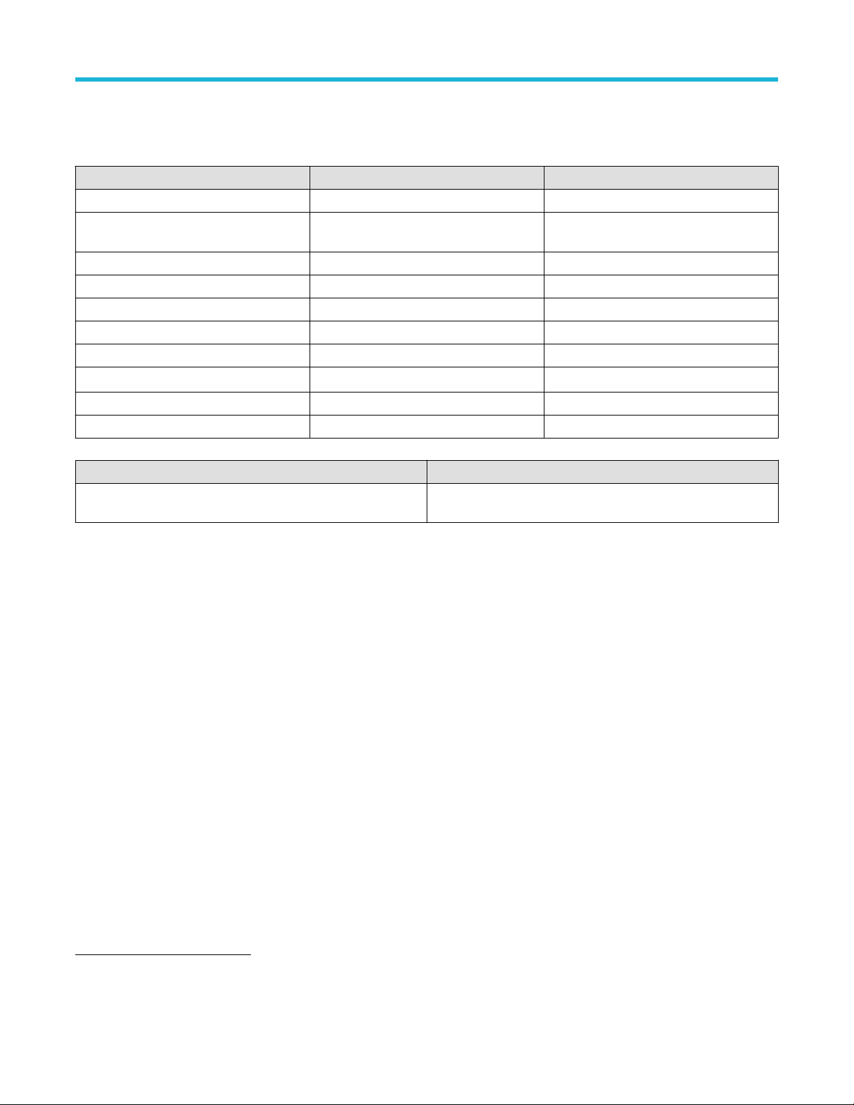
Table 1: Scope Noise Characterization application documents
To learn about Use this document
How to use the application Scope Noise Characterization Help
PDF version of this document can be downloaded from www.tek.com/downloads
Compiled HTML (CHM) version is integrated with the application. Press F1 key from the
keyboard to launch the help.
Conventions
This document uses the following conventions:
• When steps require a sequence of selections using the application interface, the “>” delimiter marks each transition between a menu
and an option.
• For example, Analyze > Scope Noise Characterization
• The term “application” refers to Scope Noise Characterization application.
• The abbreviation used for “Scope Noise Characterization” will be “SNC”.
• The term “DUT” is an abbreviation for Device Under Test.
• The term “select” is a generic term that applies to the methods of choosing an option: with a mouse or with the touch screen.
Technical support
Tektronix values your feedback on our products. To help us serve you better, please send us your suggestions, ideas, or comments on
your application or oscilloscope. Contact Tektronix through mail, telephone, or the Web site. See Contacting Tektronix at the front of this
document for contact information.
When you contact Tektronix Technical Support, please include the following information (be as specific as possible):
General information
• All instrument model numbers
• Hardware options, if any
• Modules used
• Your name, company, mailing address, phone number, FAX number
• Please indicate if you would like to be contacted by Tektronix about your suggestion or comments.
Application specific information
• Software version number
• Description of the problem such that technical support can duplicate the problem
• If possible, save the setup files for all the instruments used and the application
Scope Noise Characterization Help 10
Page 9

Getting started
Getting started
Software requirements
Scope Noise Characterization application requires DPOJET version 10.4.0.1 or later.
Supported probes
The application supports the following probes:
• P76xx
• P77xx
View software version
Click Options > About to view application details such as the software version number, application name, and copyright details. Refer to
Figure 2 on page 11
Figure 2: Scope Noise Characterization Version Number and Copyright information
The version displayed above is indicative only, the version number displayed will vary depending upon the exact version of
Note:
the application installed.
Virtual keypad and multi purpose knob
Select the
reference IDs.
icon on any of the entry text boxes and use the virtual keypad to enter alphanumeric values, such as voltage levels and
Scope Noise Characterization Help 11
Page 10

Figure 3: Virtual numeric keypad
Getting started
Figure 4: Virtual keyboard
The MP Knob Reference and are the identifiers that show which Multi-Purpose Knob (MPK) may be used as an alternate means
to control a parameter; turn the knob on the oscilloscope front panel to adjust the corresponding parameter, refer to Figure 3 on page 12
and Figure 4 on page 12. Also, the value can be entered directly on the MPK display component.
Icon descriptions
This section lists the icons displayed in the Scope Noise Characterization application and their description.
Table 2: Icon descriptions
ICON Description
This icon identifies warning / error.
This icon displays the description for various characterization
modes.
Scope Noise Characterization Help 12
Page 11

Getting started
Application directories
Table 3: Application directories
Default directory Used for
C:\Program Files\TekApplications\SNC
C:\ProgramData\Tektronix\TekApplications\
SNM\Database
The installation directory for Scope Noise Characterization
application.
Noise characterization database.
File name extensions
Table 4: File name extensions
File Extension Description
“.set” Binary file containing scope noise application setup information in a
proprietary format.
Scope Noise Characterization Help 13
Page 12

Operating basics
Launching the application
Select Analyze > Scope Noise Characterization from the oscilloscope menu bar to launch the application.
Tip: You can use the shortcut key Alt+A+N to launch the Scope Noise Characterization application.
Operating basics
Figure 5: Starting the Scope Noise Application from Analyze menu
Analyze menu entries may vary depending upon the application(s) installed.
Note:
After you click Scope Noise Characterization application, the following window appears, as Figure 6 on page 14.
Figure 6: Scope Noise Characterization application window
Application controls
This section describes the controls in the Scope Noise Characterization application.
Scope Noise Characterization Help 14
Page 13

Options menu
To access the Options menu, click in the upper-right corner of the application. It has the following selections:
Operating basics
Table 5: Options menu settings
Menu Function
Recall Recalls setup from the selected file in directory.
Recall Default Setup Recalls setup with default configurations.
Save As Saves the setup with a different file name.
Clear Database Clears all the noise entries from the database.
Help Displays the Scope Noise Characterization help.
About Displays the Scope Noise Characterization application details.
Characterize tab
The Characterize tab can be used to configure settings to perform scope noise characterization.
Scope Noise Characterization Help 15
Page 14

Operating basics
Figure 7: Characterize tab view
The Characterize tab contains the following settings:
• Reference ID: The Reference ID value can be used to distinguish the noise values characterized over the same or overlapped range
of configurations or different applications/technologies. (For example: DDR5, LPDDR5 etc.).
• Channel: Select the live channels for which the characterization must be performed. The availability of channels depends upon the
scope model and the configuration. At least one channel should be selected to start of the scope noise characterization.
• Characterize the noise sequentially for ATI and TekConnect channels.
• When the TekConnect radio button is selected, all ATI channel (for example, Channel 2) selections are disabled.
• For the dual-stack oscilloscopes, channels will appear either ATI-Channels or Tek-Connect depending on the dual-stack
configuration.
• Math: Select the Math channels for which the characterization must be performed. Make sure appropriate math expression is set
before starting the scope noise characterization. Math channels with REF waveforms will be excluded the characterization.
• Include Probe and Probe tip: Check this option if probe and probe tip should be considered while characterization. Suppose if
different types of probes are connected to multiple channels, the maximum bandwidth among all probes is considered as the probe
bandwidth. The stop bandwidth will be limited by the minimum of either oscilloscope bandwidth or probe bandwidth.
• Scale: Specify the minimum, maximum, and step values over which the noise needs to be characterized. The scale values considered
for characterization will be from minimum to maximum (both inclusive) in the increments of step size. When both min and max values
are configured the same, the noise will be measured only on that scale.
• Offset: Specify minimum, maximum, and step values of vertical offset over which the noise needs to be characterized. The offset
values considered for characterization will be from minimum to maximum (both inclusive) in the increments of step size. When both
min and max values are configured the same, the noise will be measured only on that offset.
• Bandwidth: Specify the Start and Stop values of bandwidth over which the noise needs to be characterized. When both Start and
Stop values are configured the same, the noise will be measured only on that bandwidth. When Start and Stop values are different,
the application will measure the noise for all the Bandwidth options available in the vertical menu (between Start and Stop) of that
oscilloscope.
• Sample Rate: Set the sample rate for which the oscilloscope noise needs to be performed. The default value is the maximum sample
rate supported on that oscilloscope model.
• Mode: Select the appropriate noise characterization mode by selecting from the dropdown button. There are three modes are
available:
1. Automatic
2. Custom
3. Current Scope Setting
The Automatic Mode is available only on SX oscilloscope models.
Scope Noise Characterization Help 16
Page 15

Operating basics
• Automatic Mode: In Automatic mode, for the selected sources, oscilloscope random noise will be characterized over the optimum
ranges for scale & offset matched to the oscilloscope architecture. The Bandwidth and Sample Rate are configurable. The oscilloscope
noise values are stored in the noise database after the completion of characterization.
• Custom Mode: The Custom Mode option can be used to perform noise characterization for specific values. For the selected sources,
scope random noise will be characterized over user-configured ranges for vertical scale and offset in steps. After the characterization,
the scope noise values are stored in the noise database.
Figure 8: Custom mode configuration
Considering the above configuration in the Figure 8 on page 17, the oscilloscope noise will be measured for the following values in
Custom mode.
Table 6: Example of scope noise values in Custom mode
Channel Scale Position Offset Bandwidth
Ch1 50 mV -4 div to 4 div 10 mV 10 GHz
Ch1 70 mV -4 div to 4 div 10 mV 10 GHz
Ch1 90 mV -4 div to 4 div 10 mV 10 GHz
Ch1 50 mV -4 div to 4 div 20 mV 10 GHz
Ch1 70 mV -4 div to 4 div 20 mV 10 GHz
Ch1 90 mV -4 div to 4 div 20 mV 10 GHz
Ch1 50 mV -4 div to 4 div 10 mV 11 GHz
Ch1 70 mV -4 div to 4 div 10 mV 11 GHz
Ch1 90 mV -4 div to 4 div 10 mV 11 GHz
Ch1 50 mV -4 div to 4 div 20 mV 11 GHz
Ch1 70 mV -4 div to 4 div 20 mV 11 GHz
Ch1 90 mV -4 div to 4 div 20 mV 11 GHz
• Current Scope Setting mode: In this mode, for the selected sources, oscilloscope random noise will be characterized only for
the current oscilloscope configuration. The Reference ID, Scale, Offset, Bandwidth, Sample Rate user controls are disabled. The
measured oscilloscope noise value is not persistent.
Noise Database tab
This tab displays the characterized values from the database. The values are updated dynamically during characterization and the most
recent values are displayed on the top of the list.
Scope Noise Characterization Help 17
Page 16

Figure 9: Noise Database tab displaying characterization values
The table contains the following fields:
• Channel
• Ref ID
• Scale
• Position
• Offset
• Bandwidth
• Sample Rate
• Probe Included
• External Attenuation – External Attenuator value in dB which is connected in front of the oscilloscope considered for the
characterization.
• Measured vertical noise value
• Validity – Indicates if the corresponding noise value is valid.
• Time Stamp – In "day of week, Date Month Year, Hour:Minute:Seconds” format.
• Additional Info – Contains information about Math expression, Probe type, and Probe model number.
Operating basics
For stack oscilloscope, the Noise database contains an additional column ‘Scope Config’ which indicates the configuration (ATI, TimeSync,
TekConnect or NA) for which the respective noise value was measured. NA indicates that the characterization was performed on the
standalone oscilloscope.
Updating the database
If the scope noise characterization configuration (Reference ID, Channel, Scale, Offset, Position, Sample Rate, Bandwidth, Include Probe
and Probe Tip) is unique, then a new entry is added to the database. Else, the older entry in the database will be updated with the new
values (including the noise value).
The database is updated only for Automatic and Custom mode of characterization. The noise values obtained from Current Scope
Settings mode of characterization are not stored in the database and will be lost on closing TekScope.
Result tab
The Result tab is used to query the characterized noise value for a specific oscilloscope. Enter the values for the settings in the
Configuration section, matching the values from the characterize tab. The Result section will display the Scope RN(rms) value and the
Additional Info for the matched result.
Scope Noise Characterization Help 18
Page 17

Operating basics
Figure 10: View of the Result tab
• Scope RN (rms)
The scope noise value will be displayed against Scope RN(rms) along with additional information if any.
• Additional Info
If the noise value for the required configuration is not present in the database, then the noise value will be displayed as 0V and a
warning message is displayed in the additional info section. For some reason, If the measured noise value is much higher than the
expected value, a warning message would be displayed in additional info. This additional info also contains information about Math
expression, Probe type, Probe model number.
The Scope RN(rms) and Additional Info fields are Read-only and cannot be edited.
Querying Scope RN values for Custom or Automatic Mode
In case of querying noise value characterized with Custom or Automatic mode, the Reference ID, Channel, Bandwidth, Sample Rate,
Include Probe and Probe Tip should be an exact match with the entries in the database. The attenuation value is obtained automatically
from the oscilloscope Vertical Setup for the channel.
The Scale, Offset, and Position values will be interpolated for the configured value from available entries in the database.
Querying Scope RN values for Current Scope Setting Mode
While querying for noise values with the “Use Current Scope settings” option, the following controls are disabled.
• Reference ID
• Scale
• Position
• Offset
• Sample Rate
• Bandwidth
• Include Probe and Probe Tip
Scope RN value for the required channel can be queried by changing the channels in the drop-down.
Scope Noise Characterization Help 19
Page 18

Saving and recalling setup
Saving and recalling setup
Saving a setup
You can save a setup before or after configuring the SNC. When you save a setup, all the parameters, and other configuration settings are
saved under the setup name. When you select the default test setup, the parameters are set to the application’s default value.
1. Click Options > Save As.
2. In the file browser, select the directory to save the setup file.
3. Select or enter a file name. The application appends the “.set” extension to the file name.
4. Click Save.
Recalling a setup
To recall a saved setup follow the steps:
1. Click Options > Recall.
2. Select the directory in the file browser.
3. Select a .set file and click Recall.
Recalling default setup
To recall the default settings, click Options > Recall Default Setup.
Scope Noise Characterization Help 20
Page 19

Tutorial
Tutorial
Performing characterization with Automatic or Custom Mode
Noise Characterization
1. Perform Signal Path Compensation (SPC) for the oscilloscope. Refer to the oscilloscope User Manual for more details.
2. If the measurement is performed with embed/de-embed/equalization, then configure the appropriate Mathematical expressions from
Math subsystem.
3. If there are probes to be included in the characterization, ensure that all probes are compensated and connected to the channels.
Refer to the oscilloscope manual for probe compensation details.
4. If any external attenuation is connected to any channel, then set the attenuation value on the Atten icon of Vertical Setup, as
shown in Figure 11 on page 21
Figure 11: Vertical setup
5. Make sure all the setup connections are done as per test-MOI/ procedure.
6. Start the Scope Noise Characterization application from Analyze menu.
7. Go to the Characterize tab for more information, refer to Figure 12 on page 21.
Figure 12: Scope Noise Characterization applicaiton with Characterize tab selected
8. Enter the unique Reference ID.
9. Select required live/math channels for noise to be characterized.
10. If probe need to be considered along with the oscilloscope for the noise characterization, click on the Include Probe and Probe tip
check box.
11. For SX oscilloscope select the characterization mode as Automatic
Scope Noise Characterization Help 21
Page 20

Tutorial
12. For non-SX models, select the characterization mode as Custom. Configure min, max, and step for Scale and Offset based on the
signal dynamic range on which measurements to be done.
13. Choose the Bandwidth range and Sample Rate required for the measurement.
14. Click Start and wait for characterization to complete.
15. If probes are connected and probe compensation is performed then, the following pop-up will be displayed. It is recommended to
Click No and perform the probe compensation.
Figure 13: Probe calibration information pop-up window
16. If probe compensation was already performed, then the following pop-up will be displayed.
Figure 14: Probe-tip information pop-up window
17. Either turn off the DUT or disconnect the probe tip from the DUT. Suppose if the probe tip cannot be disconnected from the DUT,
terminate the probe with a nominal tip and Click OK.
18. If any ATI channels are selected, a pop-up will come, as shown in Figure 15 on page 22. Ensure 50 Ω termination to the channel
and click OK.
Figure 15: Pop-up for 50 Ohm termination for channel
19. The application will now start the characterization process and the focus will be shifted to the Noise Database tab which will display
the settings and noise value as the characterization is performed, as shown in Figure 16 on page 23. The Latest entry will appear
on top of the list.
Scope Noise Characterization Help 22
Page 21

Figure 16: Database update during on-going noise characterization
20. Once the characterization is complete a pop-up will appear, as shown in Figure 17 on page 23. if a probe is connected to any
channel. Connect the probes back to DUT.
Tutorial
Figure 17: Characterization completion pop-up while probe is connected
You can continue performing the measurement.
Compensating noise value
1. Connect the signal and perform the Auto set so that signal occupies a minimum of 8 division on the graticule.
2. Note down the scale, offset, bandwidth, and sample rate from the Vertical and Horizontal menu of oscilloscope.
3. Make sure the correct math expressions are set in the Math menu.
4. Start the Scope Noise Characterization application and go to the Result panel, as shown in Figure 18 on page 23.
Figure 18: Compensating Noise Value
5. Enter the Reference ID for which characterization was performed.
6. Enter values of scale, offset, position, sample rate, and bandwidth noted earlier. If the probe was considered while characterization,
select Include Probe and Probe Tip option.
Scope Noise Characterization Help 23
Page 22

Tutorial
7. Select the real-time channel or math channels on which the measurement should be done.
8. The noise result appears on the Scope RN (rms).
9. The warning icon may appear beside ScopeRN value and the error/warning message is described in the Additional Info box.
The Math function will also appear if a math channel is selected for the noise query, as shown in Figure 19 on page 24.
Figure 19: Showing Math expression in "Additional Info" box
10. Note down the Scope RN value from the Scope Noise Characterization application. Go to DPOJET measurement configuration
with the RnDn tab and enter this into the Nose Compensation field. Refer to Figure 20 on page 24 and Figure 21 on page 24.
Figure 20: Noise Compensation for RN measurement in the configuration panel DPOJET
Figure 21: Noise Compensation for TN@BER measurement in the configuration panel DPOJET
Scope Noise Characterization Help 24
Page 23

Tutorial
Performing characterization with Current Scope Setting mode
Noise Characterization
1. Make sure the Perform Signal Path Compensation (SPC) for the oscilloscope is passed.
2. If the measurement is performed with embed/de-embed/equalization, then configure the appropriate mathematical expressions from
Math subsystem.
3. If there are probes to be included in the characterization, ensure that all probes are compensated and connected to the channels.
Refer to the oscilloscope manual for probe compensation.
4. If any external attenuation is connected to any channel, then set the attenuation value on the Atten icon of Vertical Setup, as
shown in Figure 22 on page 25.
Figure 22: Vertical Setup showing Atten icon
5. Make sure all the setup connections are done as per test-MOI/ procedure.
6. Recall the MOI Setup file or perform the Autoset so that the signal occupies a minimum of 8 divisions of the graticule.
7. Start the Scop Noise Characterization application from Analyze menu.
8. Go to the Characterize tab. Select required live/math channels for noise to be characterized.
9. If probe should to be considered along with the oscilloscope for the noise characterization, select Include Probe and Probe tip
check box.
10. Select the characterization mode as Current Scope Settings, as shown in Figure 23 on page 25.
Figure 23: Characterize tab when “Current Scope Setting mode” is selected
11. Click Start and wait for characterization to complete. .
12. If probes are connected and probe compensation was not performed earlier, the below pop-up is shown in Figure 24 on page 26.
Click No and perform the probe compensation.
Scope Noise Characterization Help 25
Page 24

Figure 24: Probe Calibration Pop-up
13. If probe compensation was already performed, below pop-up, as shown in Figure 25 on page 26 will be displayed.
Tutorial
Figure 25: Disconnect DUT and connect probe with nominal tip
14. Either turn off the DUT or disconnect the probe tip from the DUT. Suppose if the probe tip cannot be disconnected from the DUT,
terminate the probe with a nominal tip. Click OK.
15. If any ATI channels are selected, a pop-up will appear, as shown in Figure 26 on page 26. Ensure 50 Ω termination to the channel
and click OK.
Figure 26: Pop-up for 50 Ohm termination for channel
16. Once the characterization is complete a pop-up will appear, as shown in Figure 27 on page 27. Connect the probes back to DUT, if
any.
Scope Noise Characterization Help 26
Page 25

Figure 27: Characteriztaion completed pop-up
Compensating noise value
1. Connect back the signal.
2. Go to result tab.
3. Select Use current scope settings option.
4. Select the real-time channel or math channels on which the measurement should be done.
Tutorial
Figure 28: Result tab showing probe model and SL no.
5. The noise result appears on the Scope RN (rms).
6. The warning icon
may appear beside ScopeRN value and the error/warning message is described in the Additional Info box. The
Math function will also appear if a math channel is selected for the noise query, as shown in Figure 29 on page 27
Figure 29: Showing Math expression in "Additional Info" box
7. Compensate the noted Scope RN value from Scope Noise Characterization application into Noise Compensation in RnDn and
TN@BER configuration of DPOJET measurement. As shown in Figure 30 on page 28 and Figure 31 on page 28.
Scope Noise Characterization Help 27
Page 26

Figure 30: Noise Compensation for RN measurement in the configuration panel DPOJET
Tutorial
Figure 31: Noise Compensation for TN@BER measurement in the configuration panel DPOJET
Scope Noise Characterization Help 28
Page 27

Parameters
Parameters
About Parameters
This section describes the Scope Noise Characterization application parameters and includes the menu default settings. Refer to the user
manual of your oscilloscope for operating details of other controls, such as front-panel buttons.
Refer to the GPIB Commands on page 31 for a complete list of the GPIB Command Syntax. The topics include a complete list of GPIB
commands along with their arguments, variables, and variable values that correspond to the Scope Noise Characterization parameters.
The following tables list the option, parameters, and the default values for Characterize and Result tabs, respectively.
Characterize tab parameters
Table 7: Characterization tab options, parameters with default values
Option Parameters Default
Reference ID String “”
ATI Channel
1
TekConnect Set, Clear Set
Ch1 to Ch4 Set, Clear Clear
Math1 to Math4 Set, Clear Clear
Include probe and Probe tip Set, Clear Clear
Mode
Scale
Min Depends upon osciloscope model Depends upon osciloscope model
Max Depends upon osciloscope model Depends upon osciloscope model
Step 1 mV, 2 mV, 5 mV, 10 mV, 20 mV, 30 mV, 40
Offset
Min -3.4 V to 3.4 V -50 mV
Max -3.4 V to 3.4 V 50 mV
Step 1 mV, 2 mV, 5 mV, 10 mV, 20 mV, 30 mV, 40
Bandwidth
Start
Stop Depends upon osciloscope model Depends upon osciloscope model
Sample Rate 10 kS/s to 200 GS/s
Set, Clear Clear
Automatic2, Custom, Current osciloscope
Depends upon osciloscope model
Setting
1 mV
mV, 50 mV
50 mV
mV, 50 mV
Depends upon osciloscope model
4
Depends upon osciloscope model
Depends upon osciloscope model
3
5
6
1
Available only for standalone SX osciloscopes
2
Automatic mode is available only for SX oscilloscopes
3
Refer section ‘Mode’ of Characterize tab on page 15
4
Bandwidth start and stop values depend upon osciloscope model and the configuration (i.e ATI or TekConnect)
5
Default start and stop bandwidth values is set as the highest value available.
Scope Noise Characterization Help 29
Page 28
Result tab parameters
Table 8: Result tab options, parameters with default values
Option Parameters Default
Reference ID String “”
Channel Depends upon osciloscope model and
configuration
Use current osciloscope settings Set, Clear Clear
Scale Depends upon osciloscope model Depends upon osciloscope model
Position -5 div to 5 div 0 div
Offset -3.4 V to 3.4 V 0 V
Sample Rate 10 KS/s to 200 GS/s Depends upon osciloscope model
Bandwidth
Depends upon osciloscope model
7
Include probe and Probe tip Set, Clear Clear
Scope RN (rms) 0 mV to 50 mV 0 V
Ch1
Depends upon osciloscope model
Parameters
8
Status / Message Description
“Characterizing” Noise characterization is in-progress for the specified mode /
configuration.
6
Highest sample rate supported by the osciloscope
7
Bandwidth values depend upon oscilloscope model and the configuration (i.e ATI or TekConnect channel)
8
Default bandwidth value is set as the highest value available.
Scope Noise Characterization Help 30
Page 29

GPIB Commands
GPIB Commands
This section contains information on the Standard Commands for Programmable Instruments.
About the GPIB program
You can use remote General Purpose Interface Bus (GPIB) commands to communicate with the Scope Noise Characterization application.
GPIB commands can be used to perform the following tasks:
• Start the application.
• Save / Recall a setup.
• Recall default setup.
• Configure settings to perform noise characterization.
• Perform noise characterization.
• Query the “Scope RN(rms)” value for a particular configuration.
• Exit the application.
Argument types
The syntax shows the format that the instrument returns in response to a query. This is also the preferred format when sending the
command to the instrument though any of the formats will be accepted. This documentation represents these arguments as follows:
Table 9: Argument types
Symbol Meaning
<NR1> Singed integer value.
<NR2> Floating point value without an exponent.
<NR3> Floating point value with an exponent.
double Double precision floating point with exponent.
SNC:CHARacterize
Use this command to start or stop the characterization or to query the noise characterization status.
Syntax
SNC:CHARacterize { START | STOP}
SNC:CHARacterize?
Inputs
{ START | STOP }
Outputs
{ RUNNING | STOPPED }
SNC:CHARacterize:REFID
This command sets or queries the reference ID in characterize tab.
Scope Noise Characterization Help 31
Page 30

Syntax
SNC:CHARacterize:REFID <string>
SNC:CHARacterize:REFID?
Inputs
<string>
Outputs
<string>
SNC:CHARacterize:ATIChannel
Use this command to switch between ATI and TekConnect channels in applicable oscilloscope models.
Syntax
SNC:CHARacterize:ATIChannel { 1|0 }
SNC:CHARacterize:ATIChannel?
Inputs
GPIB Commands
{ 1 | 0 }
1 indicates ATI mode is selected.
0 indicates TekConnect mode is selected.
Outputs
{ 1 | 0 }
1 indicates that ATI mode selected.
0 indicates that TekConnect mode is selected.
SNC:CHARacterize:CH<x>
This command sets or queries channels that should be included for noise characterization.
Syntax
SNC:CHARacterize:CH<x> { 1|0 }
SNC:CHARacterize:CH<x>?
Inputs
{ 1 | 0 }
1 indicates the channel is selected.
0 indicates the channel is not selected.
Outputs
{ 1|0 }
1 indicates the channel is selected.
0 indicates the channel is not selected.
Scope Noise Characterization Help 32
Page 31

SNC:CHARacterize:MATH<x>
This command sets or queries math channels that should be considered for noise characterization.
Syntax
SNC:CHARacterize:MATH<x> { 1|0 }
SNC:CHARacterize:MATH?
Inputs
{ 1 | 0 }
1 indicates the math channel is selected.
0 indicates the math channel is not selected.
Outputs
{ 1|0 }
1 indicates the math channel is selected.
0 indicates the math channel is not selected.
GPIB Commands
SNC:CHARacterize:INCLUDEPRobe
Use this command to include probe and probe tip as part of noise characterization.
Syntax
SNC:CHARacterize:INCLUDEPRobe { 1|0 }
SNC:CHARacterize:INCLUDEPRobe?
Inputs
{ 1 | 0 }
1 indicates the channel is selected.
0 indicates the channel is not selected.
Outputs
{ 1 | 0 }
1 indicates the channel is selected.
0 indicates the channel is not selected.
SNC:CHARacterize:MODE
This command sets or queries modes for characterization.
Syntax
SNC:CHARacterize:MODE { AUTOMATIC| CUSTOM | SCOPESETTING }
SNC:CHARacterize:MODE?
Scope Noise Characterization Help 33
Page 32

Inputs
{ AUTOMATIC | CUSTOM | SCOPESETTING }
Outputs
{ AUTOMATIC | CUSTOM | SCOPESETTING }
Note: For more information about characterization modes, please refer the section Characterize tab on page 15.
SNC:CHARacterize:SCALEMAx
This command sets or queries maximum scale value.
Syntax
SNC:CHARacterize:SCALEMAx <NR3>
SNC:CHARacterize:SCALEMAx?
Inputs
<NR3>
GPIB Commands
Outputs
<NR3>
SNC:CHARacterize:SCALEMIn
This command sets or queries minimum scale value.
Syntax
SNC:CHARacterize:SCALEMIn <NR3>
SNC:CHARacterize:SCALEMIn?
Inputs
<NR3>
Outputs
<NR3>
SNC:CHARacterize:SCALEStep
This command sets or queries scale step value.
Syntax
SNC:CHARacterize:SCALEStep <NR3>
SNC:CHARacterize:SCALEStep?
Inputs
<NR3>
Scope Noise Characterization Help 34
Page 33

Outputs
<NR3>
SNC:CHARacterize:OFFSETMIn
This command sets or queries minimum offset value.
Syntax
SNC:CHARacterize:OFFSETMIn <NR3>
SNC:CHARacterize:OFFSETMIn?
Inputs
<NR3>
Outputs
<NR3>
SNC:CHARacterize:OFFSETMAx
GPIB Commands
This command sets or queries maximum offset value.
Syntax
SNC:CHARacterize:OFFSETMAx <NR3>
SNC:CHARacterize:OFFSETMAx?
Inputs
<NR3>
Outputs
<NR3>
SNC:CHARacterize:OFFSETStep
This command sets or queries offset step value.
Syntax
SNC:CHARacterize:OFFSETStep <NR3>
SNC:CHARacterize:OFFSETStep?
Inputs
<NR3>
Outputs
<NR3>
Scope Noise Characterization Help 35
Page 34

SNC:CHARacterize:BANDWIDTHSTArt
This command sets or queries start value of bandwidth.
Syntax
SNC:CHARacterize:BANDWIDTHSTArt <NR3>
SNC:CHARacterize:BANDWIDTHSTArt?
Inputs
<NR3>
Outputs
<NR3>
SNC:CHARacterize:BANDWIDTHSTOp
This command sets or queries stop value of bandwidth.
Syntax
GPIB Commands
SNC:CHARacterize:BANDWIDTHSTOp <NR3>
SNC:CHARacterize:BANDWIDTHSTOp?
Inputs
<NR3>
Outputs
<NR3>
SNC:CHARacterize:SAMPLERate
This command sets or queries sample rate.
Syntax
SNC:CHARacterize:SAMPLERate <NR3>
SNC:CHARacterize:SAMPLERate?
Inputs
<NR3>
Outputs
<NR3>
SNC:CHARacterize:MESSAGEtimer
This command sets or queries message timer. This can be used to configure the timer for popup messages as shown in following table.
Scope Noise Characterization Help 36
Page 35

Table 10: Message Timer command NR3 Value
NR3 Value Behavior
0 Characterization will continue without showing any popup messages
-1 Timer is disabled and the popup is shown indefinitely
Any positive value t Waits for ‘t’ seconds
Syntax
SNC:CHARacterize:MESSAGEtimer <NR3>
SNC:CHARacterize:MESSAGEtimer?
Inputs
<NR3>
Outputs
<NR3>
Note: NR3 value is in-terms of seconds
GPIB Commands
SNC:CHARacterize:RECORDLength
This command sets or queries record length.
Syntax
SNC:CHARacterize:RECORDLength <NR3>
SNC:CHARacterize:RECORDLength?
Inputs
<NR3>
Outputs
<NR3>
SNC:CHARacterize:MEASREPEATcount
This command sets or queries number of times AC-RMS measurement is repeated for every configuration. This can be used to measure
AC-RMS over a larger record length.
Syntax
SNC:CHARacterize:MEASREPEATcount <NR3>
SNC:CHARacterize:MEASREPEATcount?
Inputs
<NR3>
Outputs
<NR3>
Scope Noise Characterization Help 37
Page 36

Note: The final noise value is calculated as the average noise value of all the repetitions for that configuration.
SNC:Result:REFID
This command sets or queries reference ID from result tab.
Syntax
SNC:Result:REFID <string>
SNC:Result:REFID?
Inputs
<string>
Outputs
<string>
SNC:Result:CHannel
This command sets or queries channel in result tab.
GPIB Commands
Syntax
SNC:Result:CHannel {CH1-CH4 | MATH1-MATH4}
SNC:Result:CHannel?
Inputs
{ CH1-CH4 | MATH1-MATH4 }
Outputs
{ CH1-CH4 | MATH1-MATH4 }
CH4 cannot be selected for oscilloscopes with bandwidth greater than or equal to symbol 50 GHz.
Note:
SNC:Result:SCOPESETting
Use this command to choose current oscilloscope settings to get the noise value.
Syntax
SNC:Result:SCOPESETting { 1|0 }
SNC:Result:SCOPESETting?
Inputs
{ 1 | 0 }
1 indicates the channel is selected.
0 indicates the channel is not selected.
Scope Noise Characterization Help 38
Page 37

Outputs
{ 1 | 0 }
1 indicates the channel is selected.
0 indicates the channel is not selected.
SNC:Result:SCALE
This command sets or queries the scale in result tab.
Syntax
SNC:Result:SCALE <NR3>
SNC:Result:SCALE?
Inputs
<NR3>
Outputs
<NR3>
GPIB Commands
SNC:Result:OFFSET
This command sets or queries the offset value in result tab.
Syntax
SNC:Result:OFFSET <NR3>
SNC:Result:OFFSET?
Inputs
<NR3>
Outputs
<NR3>
SNC:Result:POSition
This command sets or queries position value in result tab.
Syntax
SNC:Result:POSition <NR3>
SNC:Result:POSition?
Inputs
<NR3>
Outputs
<NR3>
Scope Noise Characterization Help 39
Page 38

SNC:Result:SAMPlerate
This command sets or queries sample rate value in result tab.
Syntax
SNC:Result:SAMPlerate <NR3>
SNC:Result:SAMPlerate?
Inputs
<NR3>
Outputs
<NR3>
SNC:Result:BANDWIDTH
This command sets or queries bandwidth value in result tab.
Syntax
SNC:Result:BANDWIDTH <NR3>
GPIB Commands
SNC:Result:BANDWIDTH?
Inputs
<NR3>
Outputs
<NR3>
SNC:Result:INCLUDEPRobe
Use this command to include probe and probe tip while obtaining the result.
Syntax
SNC:Result:INCLUDEPRobe {1|0}
SNC:Result:INCLUDEPRobe?
Inputs
{ 1 | 0 }
1 indicates the channel is selected.
0 indicates the channel is not selected.
Outputs
{ 1 | 0 }
1 indicates that probe and probe tip are included.
0 indicates that probe and probe tip are not included.
Scope Noise Characterization Help 40
Page 39

SNC:Result:SCOPERNrms
This query only command gets the scope noise value.
Syntax
SNC:Result:SCOPERNrms?
Outputs
<NR3>
SNC:Result:ADDITIONALInfo
This query only command returns the additional information.
Syntax
SNC:Result:ADDITIONALInfo?
Outputs
<string>
GPIB Commands
Note: Additional Info contains details about:
1. Error/warning messages.
2. Probe model and Probe serial number if Probe is included.
3. Math Expression.
4. Filter file name and path, if present.
SNC:RECALLDEFAULTSetup
This set only command recalls the default setup.
Syntax
SNC:RECALLDEFAULTSetup
SNC:RECALLSetup
This set only command recalls the setup from the specified path.
Syntax
SNC:RECALLSetup <string>
Inputs
<string>
SNC:SAVESetup
This set only command saves the setup to the specified path.
Syntax
SNC:SAVESetup <string>
Scope Noise Characterization Help 41
Page 40

GPIB Commands
Inputs
<string>
SNC:CLEARDatabase
This set only command clears the noise database.
Syntax
SNC:CLEARDatabase
Note: All the previously characterized noise values will be lost on clearing the database.
SNC:LASTError?
This query-only command returns the contents of last error encountered. If no errors have occurred since startup, or since the last call to
SNC:LASTError?, this command returns an empty string.
Syntax
SNC:LASTError?
Outputs
<string>
SNC:VERsion
This query command returns version of Scope Noise Characterization application.
Syntax
SNC:VERsion?
Outputs
<string>
Scope Noise Characterization Help 42
Page 41

Index
A
Analyze 14
Application directories 5, 13
C
Characterize settings
Automatic Mode 17
Bandwidth 16
Channel 16
Current Scope Setting Mode 17
Custom Mode 17
Include Probe and Probe tip 16
Math 16
Mode 16
Offset 16
Reference ID 16
Sample Rate 16
Scale 16
Contacting Tektronix 10
Conventions 10
Copyright details 11
Current Scope settings
Bandwidth 19
Include Probe and Probe Tip 19
Offset 19
Position 19
Reference ID 19
Sample Rate 19
Scale 19
GPIB Commands (continued)
SNC:CHARacterize:MEASREPEATcount 37
SNC:CHARacterize:MESSAGEtimer 36
SNC:CHARacterize:MODE 33
SNC:CHARacterize:OFFSETMAx 35
SNC:CHARacterize:OFFSETMIn 35
SNC:CHARacterize:OFFSETStep 35
SNC:CHARacterize:RECORDLength 37
SNC:CHARacterize:REFID 31
SNC:CHARacterize:SAMPLERate 36
SNC:CHARacterize:SCALEMAx 34
SNC:CHARacterize:SCALEMIn 34
SNC:CHARacterize:SCALEStep 34
SNC:CLEARDatabase 42
SNC:LASTError 42
SNC:RECALLDEFAULTSetup 41
SNC:RECALLSetup 41
SNC:Result:ADDITIONALInfo 41
SNC:Result:BANDWIDTH 40
SNC:Result:CHannel 38
SNC:Result:INCLUDEPRobe 40
SNC:Result:OFFSET 39
SNC:Result:POSition 39
SNC:Result:REFID 38
SNC:Result:SAMPlerate 40
SNC:Result:SCALE 39
SNC:Result:SCOPERNrms 41
SNC:Result:SCOPESETting 38
SNC:SAVESetup 41
SNC:VERsion 42
E
Error 12
F
File name extensions 5, 13
G
GPIB Commands
Argument types 31
SNC:CHARacterize 31
SNC:CHARacterize:ATIChannel 32
SNC:CHARacterize:BANDWIDTHSTArt 36
SNC:CHARacterize:BANDWIDTHSTOp 36
SNC:CHARacterize:CH<x> 32
SNC:CHARacterize:INCLUDEPRobe 33
SNC:CHARacterize:MATH<x> 33
|
I
ICON 12
M
Menu bar 14
MPK 12
N
Name 11
Noise Database tabs
Additional Info 18
Bandwidth 18
Channel 18
External Attenuation 18
Measured vertical Noise Value 18
Offset 18
Position 18
Page 42

Noise Database tabs (continued)
Probe Included 18
Ref ID 18
Sample Rate 18
Scale 18
Time Stamp 18
Validity 18
O
Options
Recall 20
Recall Default Setup 20
Save As 20
P
Parameters
Characterize tab parameters 5, 29
Result tab parameters 5, 30
R
Result panel
Additional Info 19
Scope RN 19
S
Scope Noise Characterization 14
Shortcut key
Alt+A+N 14
Software requirements 11
Support 10
Supported probes 11
T
Technical support 10
V
Version 11
Virtual Keypad and Multi Purpose Knob 11
W
Warning 12
Welcome 9
|
 Loading...