

Page 1

SC
502
OSCILLOSCOPE
Francais
Deutsch
El
*P
.
Page 2

7
e
I
d
COMMITTEDTO
ronbc
EXCELLENCE
Tektronix,
P.O.
Box
500
Beaverton,
070-1878-01
Product
Group
Inc
.
Oregon
75
97077
PLEASE
THE
AT
CHECK
REAR
OF
OSCILLOSCOPE
Francais
INSTRUCTION
FOR
THIS
SC
Deutsch
Serial
CHANGE
MANUAL
502
Number
INFORMATION
.
S
*?A
MANUAL
First
Printing
Revised
APR
APR
1986
1975
Page 3

CopyrightC1975,
Contents
form
of this
without
the
ProductsofTektronix,
byU.S.and
TEKTRONIX,
istered
Printed
are
reserved
Copyright
foreign
TEK,
trademarksofTektronix,
in
A
U.S
.
.
©1975,
Tektronix,
1980
publication
written
permissionofTektronix,
Inc.and
patents
SCOPE-MOBILE,
.
Specification
1980TEKTRONIXINC
Le contenu decemanuelnepout
me
quocesoit
Tous
les
les
logotypes
dsposbs
Imprim#
coracttristiquesetprix
logiques
produits
.
aux
.
sans
I'accorddeTektronix
TEKTRONIX
TEKTRONIX,
USA.TEKTROW
danslecadrededtveloppements
TEK
Inc.All
rights
may
its
and/or
and
not be
reproducedinany
subsidiaries
pending
and
Inc
.
price
change
reserved
are
covered
patents
are
privileges
Inc
.
.
reg-
.Tousdroitsrbwrvbs
titre
reproduit
sont
brevettsUSet
SCOPE
Inc
.
MOBILE,
sous
quelque
Etranger
QjX
Xserlserveledroitdemodifier
techno-
.
for-
sont
Copyright
halten.Der
von
Produkte
sind
Patente
TEKTRONIX,
Warenzeichen
Gedruckt
bleiben
.
et
©
TEKTRONIX,
13
*01=-CEPRo9
©1975,
Tektronix,
von
durch
abgedeckt
vorbehalten
1975,
1980
T7
F
1980
durch
Inhalt
Inc.nicht
Tektronix,
US-and
dieser
Auslandspatente
Tektronix,
Publikation
weitergegeben
Inc
seinen
.
and
.
TEK,
SCOPE-MOBILE
von
Tektronix,
Inc
.
inU.S .A.Spezifikations-
.
c1=7
:2F&
4MT
TEK,
;k
1f0)'It*49T*o
1t#'Ii7jUldb412
;
KT
SCOPE-MOBILE,
t7
F
l
-T,
Inc.Alle
dart
werden
Rechte
ohneGenehmigung
.
Tochtergesellschaften
and
=
gri
and/odor
`sind
and
:~
<
schwebende
geschiitzte
PreisAnderungen
74±
o
T
o
3f
vorbe-
instrument
Each
stamped
or
designates
of
the
serial
unique
United
manufacture
13000000
100000
200000
300000
700000
INSTRUMENT
on
the
each
to
States
is
SERIAL
hasaserial
the
chassis.The
country
number
instrument.Those
have
identifiedasfollows
Tektronix,
Tektronix
Tektronix
Sony/Tektronix,
Tektronix
The
Netherlands
number on a
of
manufacture.The
are
assigned
six
unique
Inc
.,
Guernsey,
United
Holland,
NUMBERS
first
sequentially
manufactured
digits.The
:
Beaverton,
Ltd.,Channel
Kingdom,
Japan
NV,Heerenveen,
panel
insert,
number
last five
country
Oregon,
Ltd.,London
or
letter
digits
and
in
USA
Islands
tag,
are
the
of
Page 4

SC
502
LIST
OF
ILLUSTRATIONS
LIST
OPERATORS
SERVICE
Section1SPECIFICATION
Section
Chapitre
TABLES
OF
SAFEY
SAFETY
2
OPERATING
Introduction.. . .
Basic
Controls
General
Basic
2 INSTRUCTIONS
Introduction..
Fonctionnement..
Commandes
Fonctionnement
Application
. . . .
SUMMARY
SUMMARY
Operation
and
Operating
Oscilloscope
TABLE
. . . . . . . . . .
. . .
. . . . . . . . . . . . .
. . .
. . . . . . . . .
. . . .
. . . . . . . . .
INSTRUCTIONS
. . . .
. . . . . . . . . .
Connectors
Information
Applications
D'UTILISATION
. . . . ...
. .
et
connecteurs
. . . . . .
. . . . . .
. . . . ... . . . . . .
. . . . . . .
. . . . . .
. . . . . .
. .
. . . . . . . . .
. . . .
. . .
. . .
. . ... . . .
. . .
. . . .
. . . . .
. . . . . . . . .
OF
Page
. . .ii
. . .
. . .
. . .v
. .
2-1
. . .
. . .
. .
. . .
.
. . . .
. . . .2-2
CONTENTS
ii
iii
1-1
2-1
2-1
2-2
2-5
2-9
2-1
2-1
2-5
2-9
THE
FOR
AVOID
ANY
TAINED
YOUARE
Section
Section4CALIBRATION
Section s
FOLLOWING
USE
BY
PERSONAL
SERVICING
IN
OPERATING
QUALIFIEDTO
3
THEORY
Performance
Adjustment
MAINTENANCE
CRT
Circuit
WARNING
SERVICEINSTRUCTIONS
QUALIFIED
OF
Replacement
Board
PERSONNEL
INJURY,
OTHER
INSTRUCTIONS
DO
OPERATION
PROCEDURE
Check
Procedure
. . . . . . . . . . .
Removal
THANTHAT
. . . . . . . . . .
NOT
DO
SO
.
. . . . . . .
. . . .
. . . . . .
ONLY.T
PERFORM
CON-
UNLESS
. . . . . . .
. . . .
. . . . ..4-1
. . . . ...
. .
. . .
. . . .
. . . . .
ARE
.3-1
. .
O
Page
4-1
4-10
5-1
5-1
5-1
Kapitel2
-
;2JR
BEDIENUNGSANLEITUNG
Einf0hrung
Grundbeschreibung
Bedienungselemente
Allgemeine
Grundanwendungsbeispiele
1U#&~RA
at)IL.
iJ:l~
I,n-iL,L
~i
87
. . . . . . . . . .
.
der
and
Bedienungsinformationen
.
.
.
. . . . . . . ...
'I
flZ
. . . . . . . . .
. . . ...
. .
.
t
.
... . . . . . ... .
. .
.
. . . . . . . . . . . . ...
. . . . . . ... ... ...
:3
4,49
. . . . . . . . . . . ...
.
. . . . . . ... . . . ...
. . . . . . ... .
. . . . . . ...
. . . . . . . . .
Bedienung
Anschliisse.2-2
. . . . . .
. . . . . ...
. . ... . . . . . .2-
. . . . . . ...
. . . . . . ...
. . . . . . ...
. . . . . . . . .
.
. . . . . . . . . ...
. . . . . . .....2-2
. . . . . . . . . . . .
. . . . . . . . . ... .
Seite
. .
.
. .
.
.
:
.
. . . .2-
. . . .
2-1
2-1
2-5
2-9
2-1
2-1
2-9
Section6OPTIONS
Section7REPLACEABLE
Section8DIAGRAMS
Section9REPLACEABLE
1
5
. .
. . . . . . . . . . . . .
ELECTRICAL
AND
ILLUSTRATIONS
MECHANICAL
. .
PARTS
PARTS
. . .
. .
6-1
7-1
8-1
9-1
REVAPR
1982
Page 5

SC
502
Fig
.
No
.
The
SC
502
Oscilloscope
2-1
2-2
2-3
2-4
2-5
2-6
2-7
2-8
2-9 High-resolution
Plug-in
Controls
Measuring
waveform
Measuring
respecttoa
Measuring
points
Measuring
Measuring
pulses
Measuring
measurement
installation/removal..
and
connectors
peak-to-peak
. . .
. . . . . . . . . . .
instantaneous
reference
time
on a waveform.. . . . . . .
risetime
time
. . . . . . .
phase
with
LIST
voltage
voltage..
duration
difference
. . . . .
phase
(period)
. . . . . . . . . .
. . . . . . . .
difference
difference
increased
OF
. . . . . . . . . . .
. . . . . . . .
. .
. . . . . . . . . .
of a
. . . . . . . . .
do
voltage
between two
. . . . . .
sweep
with
. . . . . .
between
. . . . . .
. . . . . .
. . . . .
. . . .
rate.2-14
ILLUSTRATIONS
Fig
.
Page
vi
2-1
2-3
2-9
2-10
2-11
2-11
2-12
2-13
No
3-1
3-2
5-1
5-2
5-3
5-4
5-5
.
Input
preamplifier
showing
Time
pointsinthe high-voltage
Replacingthecathode-ray
board
Cross
position
crt
Variable
Time
Location
pads
Input-Output
Rear
signal
relationshipofwaveformsatthree
removal
sectional
of front
. . . . . . .
jumper
Interface
. . .
Trigger
placement
of auxiliary
. . . . . .
current
.
view
crt
Hold Off-Variable
. .
Assignments
Connector
detailed
. .
. . . . .
support,
. . . . . . . . . . . . . .
. ..... . . . . . . .
block
paths
regulator
tube,
. . . . . . .
showing
. . . . . . . .
Z-axis
For
. . . . . . . .
diagram
... . . . . . .
and
placement
crt
shield
input
solder
Plug-In
. . ..3-7
circuit
. . . .
and
.
. . .
Sweep
. . . .
.
. . . .
. . .
Page
3-1
5-2
5-3
5-3
5-4
5-5
Table
No
.
1-1
1-2 Horizontal Deflection
1-3
1-5
1-6
1-7
1-8
Vertical
Triggering
Calibrator
Power
Rear
Environmental
Deflection
System
. . . . . .
Supplies.. ...
Interface
System
. . . . . .....
. . . . . . . .
LIST
. . . . . . . .
System
. .
.
. . . . . . . . . . . . . . . .
. . . . . ...
. . . . . . . . . . . ..1-4
. . . . . . . . . . . . .
. . . . . . .
. . . . . . . . . . .
. .
. .
O
Page
1-1
1-3
1-5
1-5
1-6
1-7
F
TABLES
Table
No
.
1-9
3-1
4-1
4-2
4-3
4-4
Mechanical
Channel
ListofTest
Vertical
Tolerance
Horizontal
Volts/Div
Switch
Deflection
. .
. . . . . . . . . . . . . .
Logic
Equipment
Accuracy
. .
. ...
. . . . . . . . . . . ...
Deflection
Attenuator
Check
. . . . .
Table
. . . .
. . . . .
Requirements
and
Accuracy.. . . .
. . . . . . . .
. . .
. .
. .
. .
Page
1-7
3-2
4-1
4-2
4-6
4-12
REVAPR
1982
Page 6

SC
502
OPERATORS
The
general
is
for
warnings
manual where
summary
Terms
CAUTION
could
WARNING
that
could
Terms
CAUTION
mediately accessibleasone
hazard
DANGER
accessibleasone
Symbols
safety
informationinthis
operating
both
and
.
In
This
statements
resultindamagetothe
statements
resultinpersonal
As
Marked
indicatesapersonal
property
to
indicatesapersonal
As
Marked
DANGER
Protective
ATTENTION
and
cautions
they
apply,
Manual
identify
on
including
reads
on
-
willbefound throughout
identify
Equipment
the
High
ground
-
Equipment
part of
the
servicing
but
conditionsorpractices
equipmentorother
injury or lossoflife
the
marking
refertomanual
personnel.Specific
may
not
appear
conditions
injury
hazard
the
reads
equipment
injury
voltage
(earth)
marking, or
hazard
.
.
terminal
or
itself
immediately
.
SAFETY
summary
the
in this
that
property
practices
.
im-
not
.
.
protective
conductorinthe
tion
Danger
Upon
accessible
trols
.
electric
Use
Use
a
product
Use
Refer
personnel
Use
To
voltage
list
SUMMARY
ground
.
Arising
loss of
conductive
that
may
shock
the
Proper
only
the
power
.
onlyapower
cord
and
.
the
Proper
avoid
fire
rating
for
your
product
connectionbywayofthe
power
cordisessential
From
LossofGround
the
protective-ground connection,
parts
(including
appeartobe
.
Power
cord
cord
connector
Fuse
hazard,
and
use
current
.
insulating)
Cord
and
connector
that
is in
good
changes
only
the
ratingasspecifiedinthe
grounding
for
safe
knobs
and
can
render
specified
condition
to qualified
fuseofcorrect
for
.
service
opera-
all
con-
an
your
type,
parts
Power
This
that
supply
and
grounding conductorinthe
safe
Grounding
This
torofthe
power
connectingtothe
Source
productisintended to
will
not
apply
more
conductorsorbetween
ground.A
operation
productisgrounded
protective
.
the
power
cord.To
cord
intoaproperly
Product
product
than
ground
through
avoid
operate
inputoroutput
fromapower
250
volts
rms between
either
supply
connectionbywayofthe
power
cordisessential
the
grounding
electrical
wired
shock,
receptacle
terminals.A
source
the
conductor
for
conduc-
the
plug
before
Refer
fuse
Do
Not
To
avoid
explosive
certified
Not
Do
To
avoid
without
the
coversorpanels
plug-in
replacementtoqualified
OperateInExplosive
explosion,donot
atmosphere
for
such
operation
OperateWithout
personal
viaaplug-in
injury,donot
operate
unlessithas
.
Covers
installed.Do
extender
service
Atmospheres
this
productinan
been
operate
not
apply
.
personnel
specifically
this
REVAPR
.
product
power
1982
to
Page 7

SC
502
Do
Not
Do
not
product
aid
and
resuscitationispresent
Use
Care
Dangerous
To
avoid
tions
and
Service
perform
unless
another
When
voltages
personal
components
SERVICE
FOR
Refer
Alone
internal
Servicing
injury,
serviceoradjustment
person
existatseveral
do
while
QUALIFIED
alsotothe
capable
.
With
not
powerison
of
Power
pointsinthis
touch
exposed
SAFETY
SERVICE
preceding Operators
of this
rendering
On
.
first
product
connec-
.
SUMMARY
PERSONNEL
Safety
Disconnect
soldering,
Power
productisintended to
This
that
will
supply
and
ground.A
grounding
safe
operation
power
replacing
or
Source
not
apply
conductorsorbetween
protective
conductorinthe
.
Summary
before
components
more
ONLY
.
removing
operate
than
ground
power
protective panels,
.
fromapower
250
volts
rms
either
supply
connection
cordisessential for
source
between
bywayofthe
the
conductor
REV
APR
1982
iv
Page 8

SC
502
CONSIGNES
Ce
rappel
des
consignes
utilisateursetau
mentsetpr6cautionsi3respecter
&
cheque
ge
te
Termes
Les
constancesouop6rations
de
Les
circonstances
ou
Repisres
CAUTION
risquedeblessure
risque dventuelded6t6rioration
DANGER
imm6diat
fois
qua
. IIestAnoter
rubriquederappel
utilisds
paragraphes
I'appareiloude
paragraphes
dangereuses
risque
blessure)
de
grav6s
(ATTENTION):ce
(DANGER):ce
pouvant
gdndralesdesdcuritd
personneldemaintenance.Les
l'utilisation
qua
ceux-ci
.
danscemanual
intitulds
tout
intitul6s
.
sur
I'appareil
non
entrainer blessuresoumort
du
peuvent ne pas
ATTENTION
pouvant
6quipement
autre
AVERTISSEMENT
pour
perceptibles
mot
s'adresse
avertisse-
sont
annot6s
chassis
d'alimentation
identifient
entrainerlad6tdrioration
.
I'utilisateur
mot
identifie
imm6diatement
1'appareil
de
indique
les
zones de
ce
dans
figurer
dans
les
indiquent
(dangerdemort
zones
les
ouun
.
risque
.
aux
manual
I'exi-
cet-
cir-
les
de
DE
SECURITE
MissAla
Une
relictbla
tation.Pour
cordon
pondante
pareil.Pour
xioni3la
danslecordon
Danger
masse
En
ments
commandes
choc
UtiliserIscordon
N'utiliser
d6s pour
parfait
changementdecordon
masse
fois installd
masse6I'aide
dviter
d'alimentation
avantdeconnecter
utiliser
masse,
provoqud
casdecoupuredela
conducteurs
apparaissant
6lectrique
qualecordon
votre
dtat.Saul,
de
1'appareil
danslechassis
d'un conducteurducordon
tout
choc
dans
I'appareil
rdalisdeaumoyen
d'alimentation,
parlacoupuredeconnexion
accessibles(ycompris
.
d'alimentation
appareil
personnel
un
d'alimentation,
dlectrique,
une
prisededistribution
I'entrdeoules
toute
an
d'un
indispensable
est
connexiondemasse,
isolants)
d'alimentation
Utiliseruncordon
.
et
prises
peuvent
qualifid
.
I'appareil
d'alimen-
insdrerlaprise
sortiesdeI'ap-
sdcuritd,
approprid
une
conne-
conducteur pr6vu
.
tous
les
boutons
provoquer
etlaprise
d'alimentation
peut
et
recomman-
proc6der
est
du
corres-
de
6I6-
un
an
h un
Symboles
grav6s
y
0
Source
L'appareiI
d'alimentation
teurs
tation
une
prdvu
d'alimentation
est
d'alimentation
etlaterre.Pour
connexionAla
denslecordon
I'6quipement
sur
-
Haute
DANGER
Borne
ATTENTION
conqu
maximalede250Vefficaces
masse,
massedeprotection
de
pour
fonctionner8partir
ou
entre
cheque
utiliser
rdalis6eaumoyen
d'alimentation,
tension
-sereporteraumanual
conducteur
I'appareilantoute
est
(terre)
d'une
source
les
entre
d'alimens6curitd,
conducteur
d'un
indispensable
conduc-
.
UtiliserIsfusible
dviter
tout
Pour
fusible
le
remplacement
od:mime
placement
qualifid
sonnel
pas
Ne
Pour
une
Ne
Pour
capotsoupanneaux
pro
utiliser
dviter
atmosphisre
pas
d6monter
dviter
longateur
risque
recommandd
doit
type,
mime
fusiblenedoit
de
.
I'appareilanatmosphisre
toute
explosion,
de gaz
toute
blessure,
.
approprid
d'accident
pour
toujours
tensionetmime
explosifs
les
capots
Ne
pas alimenterletiroirhtravers
.
(incendie
votre
appareil.Le
correspondreaufusible
etre
effectud
ne pas
utiliser
.
ne
pas
utiliserceproduit
. ..)n'utiliser
courant.Un
qua
cat
fusible
de
rempla-
rem-
par un
per-
explosive
appareil
sans
qua
dans
un
REVAPR
1982
Page 9

SC
502
Ne
pas
d6panner
Ces
consignes
lifid.II
est
6galement
gneedes6curitd
r6glage
doit
s'effectuerenpr6sence
capable
Agir
tension
Des
pareil.Pour
d'assurer
avec
pr6caution
potentiels
dviter
tout
s'adressent
indispensabledese reporter
pr6c6dentes
lee
premiers
dangereux
blessure,
toute
CONSIGNES
UNIQUEMENT
AU
seul
exclusivement
lorsque
existent
PERSONNEL
Toute
d'une
secours
I'appareil
en
ne pas
h un
personnel
intervention
autre
casdedanger
an
est
diffdrents
pointsdeI'ap-
intervenir
consi-
aux
interne
personne
.
sous
sur
lee
qua-
ou
DE
SECURITE
DES
DE
connexions
sion
neaux,
Source
Cet
d'alimentation
lee
masse.Pour
Alamasse
cordon
TINEES
MAINTENANCE
.
Ddbrancher
soudureouremplacementdecomposants
d'alimentation
appareil
conducteurs
rdalisdeaumoyen
d'alimentation
et
les
composants
('alimentation
est
conqu
qui
n'applique
d'alimentationouentre
utiliser
I'appareilantoute
alors
pour
fonctionnerApartir
pas
d'un
est
indispensable
qua
I'appareil
avantleddmontage
plusde250Vefficaces
un conducteuretla
sdcuritd,
conducteur
.
est
.
d'une
une
pr6vu
des
connexion
dans
sous
pan-
source
ten-
entre
le
ADD
APR
1982
VI
Page 10

SC
502
SICHERHEITSANGABEN
Die
allgemeinen
Angaben
der
nal.Spezielle
Handbuch
nicht
erscheinen
In
diesem
VORSICHTSHINWEISE
Zerstrirung
ren
k6nnen
WARNUNGSHINWEISE
PersonenschAden
lich
sind
.
Markierungen
CAUTION
ges BerOhren an
Personenschaden
Stelle
am
Gerdt
DANGER
BerOhrenaneiner
den
entstehen
Sicherheitsinformationen
dienen
Warnungen
finden,
zu
.
Handbuch
des
GerAtes
.
auf
-VORSICHTweist
selbst
.
-GEFAHR
kann
dem
Anwender-und
and
mOssen
BEGRIFFE
erlAutern
oder
erlAutern
f0hren
einer
k6nnen
dem
Gerat
darauf
nicht
entstehen
weist
darauf
zugAnglichen
.
in
Serviceperso-
Hinweise
jedochindiesen
anderer
Bedingungen,
unmittelbar
hin,
sind
Bedingungen,
GegenstAnde
oder
IebensgefAhr-
hin,
daBdurch
zugAnglichen
kann,
oder
daB
durch
Stelle
Personenscha-
diesem
Oberall
Angaben
die
fOh-
die
zu
zufAlli-
Schaden
zufdlliges
Tell
im
zur
FUR
dung
Ein-und
drahtete
Schutzleiter
oder
schen
raten
Gefahr
Durch
baren, leitenden
Bedienungselemente,
schen
Verwendung
Verwenden
einheit
finden
FOr
ziehen
Handbuches
Ein
schultem
DEN
von
elektrischen
AusgAnge
Steckdose
mehreren
SchlAgen
Leitungenzuverbunden
durch
eine
Schiag
Sie nur
geeignet
.
detaillierte
Sie
sich
Austausch
Personal
ANWENDER
ist
nicht
als
GerAten.Zur
sind
fehlende
fehlende
Teile
bei
der
eines
sind
Informationen
bitte
.
von Kabeln
vorzunehmen
Schidgen
der
einzustecken
einzige
die
GerAte
Schutzerde
(einschlieBlich
die
BerOhrung
richtigen
Netzkabel,
and
auf
vor
Netzsteckerineine
Verbindung
Vermeidung
untereinander
.
Schutzerde
isoliert
Netzkabels
die
die
sichingutem
Ober
Abbildungen
and
Steckern
.
der
Beschaltung
korrekt ver-
.
Verwenden
zwischen
von
mit
konnen
sind)
auslbsen
for
Kabel
alle
Kn6pfe und andere
einen
.
die
Versorgungs-
Zustand
and
Stecker
innerhalb
ist
nur
der
Sie
den
zwei
elektri-
sepa-
berOhr-
elektri-
be-
be-
des
von
ge-
SYMBOLE
-In
diesem
Markierungen
Netzspannungsvemorgung
Die
Betriebsspannung
Oberschreiten
aneine
halb
handen
MasseanschluB
Dieses GerAt
gungseinheit
Handbuch
Dieses
zu
finden
GEFAHR-Hochspannung
Schutzerdungskontakt
ACHTUNG
Handbuch
Versorgungsleitung
des
NetzanschluBkabels
sein,
der
Symbol
lassen
sind
auf
dem
and
istandie
mit
des
wird
Ober
mit
Erdpotential
GerAtemasse
zeigt
an,woVorsicht
ist,
oder
wo
.
Gerat
.
beziehen
-
.
fOr
dieses
GerAt
Versorgungsleitungen
Masse
and
muB
ein
verbunden
Gerates
den
Schutzleiter
verbunden.Zur
walten
Informationen
.
Sie
sich
dart
250Venicht
anzulegen.Inner-
Schutzleiter
der
auf
bzw
ist
.
Versor-
Vermei-
zu
das
vor-
Verwendung
Zur
Vermeidung
genzuverbunden,
aufgef0hrt
entsprechend
von Sicherungen
Ersatz
vorzunehmen
Arbeiten
Zur
Vermeidung
dieses
wenn
Entfemen
Zur
hAuseteilezuentfernen.Auch
.
se
GerAtesinexplosiver
das
Vermeidung
nichtinBetriebzunehmen
Arbeiten
Zur
Vermeidung
nicht
ohne
sollte
nicht
werden
.
einer
von
sind
and
sind
.
Sie
nichtinexplosiver
von
GerAt
nicht
Sie
keine
von
Sie
nicht
von
GehAuseinBetriebzunehmen.Der
Ober
einen
richtigen
BrandschAden
dieinden
dieinSpannungs-and
.
ist
Explosionen
dafOr
Gehauseabdeckungen
PersonenschAden
ohne
PersonenschAden
VerlAngerungsadapter
Sicherung
sind
Teilelisten
nur
vongeschultem
Umgebung
ist
die
Umgebung
geeignet
ist
.
Gehauseabdeckung
das
ist
GerAt
nur
Sicherun-
dieses
Inbetriebnahme
zu
.
sind
GerAtes
Stromwert
Personal
unterlassen,
keine
Ge-
ohne
GehAu-
ist
das
Ger9t
Einschub
betrieben
ADDAPR
1982
Page 11

SC
502
Beziehen
Sie
Fiihren
Nehmen
arbeiten
im
um
suchezuleisten
Lassen
Sie
aneinem
arbeiten
An
verschiedenen
gefghrliche
keine
Sieandem
vor,
wenn
Bedarfsfall
Sie
besondere
unter
Spannungen.Zur
SICHERHEITSANGABEN
NUR
Sie
sick
auch
Servicetatigkeiten
Gerat keine
nicht
eine
andere
Erste
Hilfe
oder
.
Vorsicht walten,
Spannung
StellenimGerAt
Vermeidung
FUR
auf
die
vorangehenden
alleine
Service-
Wiederbelebungsver-
stehenden
liegen
Person
hohe
oder
verfi)gbar
wenn
von
Personen-
GESCHULTES
durch
Einstell-
ist,
GerAt
and
damit
FUR
DEN
PERSONAL
SERVICE
Sicherheitsangaben
schAden
ren,
Vor
setzen
entfernen
Netzspannungsversorgung
Die
iiberschreiten
aneine
halb
handen
sind
solche
wAhrend
dem
Betriebsspannung
des
Betriebsspannung
Entfernen
von
Bauteilen
.
and
istandie
Versorgungsleitung
NetzanschluBkabels
sein,
der
mit
Stellen
von
ist
immer
fur
GerAtemasse
fur
den
Anwender
and
Bauteile
anliegt
GehAuseteilen, LOten
die
dieses
Gertit
Versorgungsleitungen
and
Masse
muf3
nicht
.
Betriebsspannung
dart
250
anzulegen.Inner-
ein Schutzleiter
verbunden
.
zu
beriuh-
oder
Vets
ist
.
Er-
zu
nicht
bzw
vor-
.
ADD
APR
1982
viii
Page 12

t~
f1fI
502
SC
I
Ir
-q=a7x*omm
"01011*mggI
0)
zb
ti
tl0~Z6~
s
*
3
o
0»UrrT1- .
~fs.~~
*B_htzlzi~ t'1,Zo3mlf
CAUTIONIIhf*fsjtU*jEf-1tzI1J
;T
-
a
J
~'5ttb
NGERtt
DA
5tib>iba 3
,~b
,
kJ*ICM
.%3~i-%
t--litom#ic
"
Z
3
05j.5-T
LZ~~-~'
"
Yc
IC
L %
L
NT Ut--h4-H
o
`ftm
.
fecmixPeaITI'5
.9029IcM9Ae
IJ
-
.
nICItMtp-qk3
4AR
v3i4
~-K$P0»-70lIEI`MAhLZTt0
~
xm*f#Om*
%A~
LZFtOa
Itam-
lames-
16z
1
v
-
.
it
3tz-~b
1L,
CS
=7
-
i
2,
,
4
tPM71h
~'i7t~tLTC~td6~~.Xf*0)I%A
#
It
3t--bb,
-
sr
L
I`
l 5T
F
F
Icmfxb>tsLICLre*5bbTLtL1o
itNILA1A~3
h
7
b
,
95
h
~'
.
o
tODAet3ftL"
6~#x
c
T
~..0~>>tSt#~llSZ~~t~lfiZ<saA2~-
c0)
(Zia~t&E*
on
~-4I
Jts1'12,
y
Ittiff-"~UA
V!
IRA
*M
'7i
zt_b5IL
250VrmsJUNODV_ff4»aR'IZfFMU11
FPaI75
,
-F0)9-7,W-MftL'ZTtro
uq
:3
1tz-Itt010Hle~
-
.
.
VF
Vi~
M-ffii
=-FLT
cVM-F
t
late=-FLn*4
Ir-16
tzttaF
La-x
71J
;CDt:~b
t
r
a-Xo~zhm"r
=~Iclst
t}ts6~TTt6~o
L!s
IIfF
Jilt-,
-f7T-f
-
t}ts6N
C.T'tL".
~glcm-"b
o
.
L
-1
t
o
.
:tta-FtL1.
i0,)
O~XIi:
=s9~i
3
gait,
II*f*Iu&&q4rz-
.~6"Zt
>~f=iv=9
.Ir-1C$'ctt'L'Zo3f±IcA
-JI'
F"=i
-f
t
5
tsTTz
it
fe
,
~J~~±7
Icy 3
hlitUtzIV'M
Z~
IX
ADDAPR
1982
Page 13

SC
502
AN
P~
MicIIAMEOD
Mih'rSt-b,
n53IbS
WE
*A
V/A*
t53'~~ct~
AILi14~i?MWSOZTt
#-
tx
"=i=
"F,-1'F-J-
h
/L'~O~fel
o
t,
"
o
ODiTV"
-
POD
S~Ci~3~p~Jy
.
. *
i
,
MON
'~
.F
A,CDITR
-
6
"o
iJ:ti.,~
h
rW-Dz'Tt,("o
"iYf-f,
AR
AODx
T75-V«
ADD
APR
1982
Page 14

502
SC
The
502
Oscilloscope
SC
REVAPR
1982
Page 15

SPECIFICATION
Section
1-SC
502
Performance
The
electrical
with
the
following
1.The
2
3
Deflection
Calibrated
Variable
instrument
ambient
The
instrument
.
ment
whose
Allow twenty minutes
.
specified
storageina
Characteristics
Factor
Range
Conditions
characteristicsinthis
conditions
temperature
limits
accuracy;sixty
high
Range
:
must have
between
mustbeinanon-condensing
are
described
warm-up
humidity
specification
been
+200C
under
time
minutes
after
(condensing)
1
mV/div
sequence
At
least2.5to1
are
valid
adjustedatan
and
+300C
environ-
Environmental
for
operation
exposure
environment
VERTICAL
Performance
to
.
20
V/divin14
.
to or
Table
DEFLECTION
istic
.
.
gether
to
plete
.
performanceofa
1-1
Requirements
stepsina
Any
conditions that
are
expressly
The
electrical
with
statement
SYSTEM
1-2-5
statedaspart of
and
their
related
of
calibrated
Continuously
steps
deflection
are
uniquetoa
environmental
validation
the
electrical
instrument
Supplemental
variable
and
extends
factor
particular
that
characteristic
performance
procedures areacom-
and
.
Information
between
maximum
to at
least
character-
.
limits
environmental
calibrated
uncalibrated
V/div
50
.
to-
DC
Balance
(+15°C
Accuracy
+15°C
0°C
Linearity
HF
Bandwidth
5
2
1
to
+35°C)
to
+35°C
mV/divto20
5
1
mV/div to2mV/div
+50°C
to
mV/divto20
Risetime
Typical
aberrations
mV/div At
mV/div At
V/div
V/div
(calculated)
step
response
0.5div+1mV.
±2%
±5%
Derated
0
as a
graticule
At
accuracy
div
.1
or
div
2
limits
least15MHz
least10MHz
least
5
less
signalispositioned
.
MHz
byan
additional1%.
of
compressionorexpansion
between
.
.
.
the
23ns
or less
t
2%,
3%
limitedto5
.
peak-to-peak
divisions
major
less.Signal
or
.
REV
FEB
1982
Page 16

I
I
1
Specificatlon-SC
Characteristics
Response
AC
LF
Common
(CHI-CH2
Channel
Displayed
Typical
warm-up,
CHIorCH2
Mode
Display
Isolation
Noise
Trace
constant
mV/divto20
5
1
mV/divto2
Impedance
Maximum
Drift
Input
Input
502
Rejection
Mode)
(after1hour
line
voltage)
V/div
mV/div
Voltage
Ratio
Table
1-1 (cont)
Performance
less
or
withaccoupling
factor
settings
display
.
peak-to-peakat1mV.
.
10Hz
At
least30to1at1MHzorless
deflection
2%orless
15
MHz
0.2mVorless
1
M11
±1%
Requirements
.
related
with
crosstalk
to
same
Supplemental
1Hzor
Common
sions,10div
probes
probe
Input
I
less
Less
Less than0.3
Paralleled
350V(dc+peak
peakacat1kHz
recommended
250Vto10kHz
100
less
mode
CMRR
compensation
signal
than0.01%
than0.1
nominally
kHz
.
Information
with
X10
probe
.
signal
limitedto±
.
peak-to-peak
above
related
crosstalkistypically
.
div/hr.and0.03
mV/hr.and0.1
ac),
or less
peak-to-peakaclimit
derating
With
1
kHzislimited
matching
mV/°C
47pF
by
.
700Vpeak-to-
.
Above1kHz
to 25Vabove
5
X10
.
div/°C
divi-
by
.
.
is
Position
Delay
Line
Display
CHIorCH2
ALT
CHOP
CHI
Trigger
Range
Modes
minus
View
CH2
At
least±6
Selected
I
Alternates
other
Chops
Displays
and
Triggering
selected
button
divisions
inputisdisplayed
display
sweep
display
algebraic
CH2
.
waveformisdisplayed
Display
depressed
is
.
of
of
CHI
difference
Mode
.
.
CHI
and
when
.
and
CH2
CH2
.
between
instead
TRIG
every
CHI
VIEW
Nominally
leading
Chop
Triggering
of
waveformisnominallyatCRT
center
140ns.
edgeofthe
least
rate
at
pointonthe
.
Permits
triggering
250kHz
displayed
viewing
waveform
.
vertical
the
.
REV
FEB
1982
Page 17

HORIZONTAL
1-2
Table
DEFLECTION
SYSTEM
Specification-SC
502
Characteristics
Sweep
Rates
Calibrated
Variable
Accuracy
+15°C
0
50
0.5ws/divto0.2ks/div
0°Cto+50°C
Linearity
Range
Range
to
+35°C
s/divto0.1s/div
.5
ms/divto1
s/div
Performance
0.5s/divto0.2ps/divin20
sequence.X10
fastest
At
least2.5
Derate
calibrated
Unmagnified
accuracy
to
±3%
±2%
±3%
Horizontal
1
rateto20
.
by an
Requirements
additional
stepsina
Magnifier
ns/div
.
Magnified
±4%
+3%
+4%
1%
1-2-5
extends
X10
.
Supplemental
Continuously
sweep
uncalibrated
The
variable
selectable
Rate or
Measured
sions
fied
sweep
Typically5%(0.1div)orless
timing
center8divisions
variable
rates
and
rate to at
control
between
Variable
over
excluding
beyond
over
any2div
Information
between
extends
Holdoff
center8displayed
the
.
slowest
least
internally
is
Variable
the
functions
first50ns
the
100th
internal
calibrated
1
.25
s/div
Sweep
.
and
magni-
division
change
within
.
divi-
.
in
the
Registration
MAG
Length
Sweep
Position
External Horizontal
Range
Fully
CW
Fully
CCW
Bandwidth
Deflection
Difference
Phase
Input
Impedance
Maximum
Factor
Input
Input
Voltage
divisions
0
.5
At
least10.0
Startof1
center
10th
leftofcenter
At
50
3° or
1
MS2
ms/div
graticule
division
feasts
2
mV/div±5%
lessto50
±2%
or less
divisions
sweep
line
of1ms/div
graticule
MHz
.
.
kHz
.
.
.
positionstoright
.
sweep
line
.
.
positions
of
to
Low
trigger
withaccoupling
Paralleled
350V(dc+peak
peak
frequency
coupling
at1kHzorless
response
selection,
.
nominally
determined
50Hzor
by47pF
ac),
350Vpeak-to-
.
by
less
.
REV
FEB
1982
Page 18

Specification-SC
502
Table
TRIGGERING
1-3
SYSTEM
Characteristics
Trigger
(Minimum
Sensitivity
peak-to-peak
quired)
MHzorless
5
MHzto15
5
Coupling
DC
AC
AC
LF
REJ
Trigger Level
(Normal
modes
External
(Same
and
only)
Trigger Input
as
Impedance
Maximum
signal
MHz
Range
Single
Sweep
Ext.Horizontal
Input
Voltage
re-
input)
CHI
0
1
At
least±8.0
±1.2Vexternal
least
1
MS2
±2%
Performance
CH2
or
div
.4
div
.0
divisions,
.
Requirements
External
150
CH1orCH2,
.
60
mV
mV
and
at
Supplemental
Minimum
dc
.
Minimum
low50Hz
Minimum
low 5
kHz
Paralleled
V
(dc+peak
350
at1kHz
peak
requirements
signal
requirements
signal
.
requirements
signal
.
nominally
or less
Information
47pF
by
ac),
350
.
extend
increase
increase
.
V
peak-to-
to
be-
be-
Modes
Auto
Normal
Single
Holdoff
0
Time
s/divto1
.5
(Auto
Sweep
0.5ms/divto10
ps/divto0.2us/div
5
Variable
Holdoff
button
ms/div
gs/div
Range
out)
free-runsinthe
Sweep
triggering
Sweep
Upon
signal
will
triggering,
not run again
button
.
.
run unless
not
unless
sweep
absenceofa
triggered
runs
once
reset
by
.
and
pushing
will
Reset
TRIGGER
varies with
peak
quencies
minimum
Measured
Select
Nominally10ms
Nominally
Nominally<2,us
At
LEVEL
the
range
.
below
signal
at
Auto
100;ts
least20to
triggering
Not
recommended
30
requirements
rear
interface
mode
.
.
.
range.The
1
controlisinternally
the
Variable
functions
Sweep
.
range
automatically
signal
Hz.Below
and
free
selectable
or Variable
peak-to-
for
100
increase
20B-21B.
pins
run
sweep
Variable
between
Holdoff
fre-
Hz
.
.
REV
FEB
1982
Page 19

Characteristics
CRT
Type
Graticule
Phosphor
Acceleration
Geometry
Potential
and
Orthogonality
(exclude4corners)
Intensity
Control
Function
Table
1-4
CATHODE
RAY
TUBE
Performance Requirements
Bowingortiltis0.1divisionorless
respecttograticule
lines
Table
.
1-5
CALIBRATOR
with
Supplemental
T3350
.
8X10
divisions
(0 .64
cm/division)
P31
.
12kV(-1.9kV
When
Intensity
clockwise
lected,
visible
.
the
and
sweep
Specification-SC
Information
with0.25
inch/division
.
cathode)
.
controlisrotated
Single
Sweep
baseline
modeisse-
spotisclearly
502
fully
Voltage
Frequency
Rise
and
Output
+20V
Impedance
-
Characteristics
Falltimes
Characteristics
0
.6
Twice
Performance
V
peak-to-peak,
the
power
Requirements Supplemental
±
I%
line
frequency
Table
POWER
Performance Requirements
.
.
1-6
SUPPLIES
than
Less
Approximately
Supplemental
20.0V ±0
-20V -20.0V ±0
+5V
-5V
+70
-70
Power
+33.5V
V
V
Module
Supply
Currents
+5
.07V±0
-5
.00V±0
+70V-3V,+4
-69V
+3V,
Typically
420mA.
1
As
.05V.
.05V.
.08
.20
.
120S2.
V
.
V
.
V
-4V
Information
Information
.
Fuse
REV
-33.5V
+11.5V
25
VAC
Data
F800
F970
FEB
1982
Typically
Typically
400mA.
400mA.
Typically10mA
0
.3A,
3AG,
slow blow
0
.75A,
3AG,
.
fast
blow
.
.
1-5
Page 20

Specification-SC
502
Table
1-6
(cont)
Characteristics
Mainframe
Recommended
Interval
Warmup
Time
Characteristics
External
(Delayed)
Power
Adjustment
Line
Gate
Draw
Input
Performance
REARINTERFACE
Performance
Requirements
Table
1-7
Requirements
Supplemental
29
Typically
than1watt
POWER
1000
20
minutes,60minutes
or
storage
environment
watts
with
OFF
.
hoursor6
high
in
.
Supplemental
Pins
2313-2213.ECL
ating
between
nally
100S2.
Upon
sweep
SELECT
will
from
sweep
state
GATE
transition
will
truncate
Information
or less operating,
mode
switch
set
months
.
after
humidity
exposure
(condensing)
Information
balanced
+5Vand
input
ground
.
transitiontological
free-run
once
and
INPUTisgrounded.A
logical
high to
low
if itisrunning
to
oper-
Nomi-
reset
state
.
less
to
high
if
Gate
Select
Intensify
CH1
Trigger
Triggered
Holdoff
Ramp
Output
Output
Input
Input
Gate
Output
Output
Pin
2413.Ground(1kitorless)
external
signal
operation
Pin
ing
low
tion.Open
state
Pins
gate
as the
.
circuit
Open
.
1913.Single
between
state
+5
causes
ended
V
circuit
.
2713-2813.Analog
sweep
causes
ECL
and
ground.A
noticeable
defaults
output
resistanceofapproximately
tivity is
typically50mV/div
is
typically4MHz
Pins
2513-2613.ECL
ating
between
high
state
and
sweep
Pins
2013-21
ating
between
Pin
18A
.
Analog
ramp.Typically0V
sweep
V
.
+6
.4
Output
approximately1kit.Not
sweep
rates
.
+5Vand
indicates
can
not be
B
.
ECL
+5
output
resistance
faster
balanced
ground
holdoff condition
a
triggeredorgated
balanced
V
and
of
recommended
than1ps/div
selects
controlling
normal
input
operat-
intensifica-
to logical
with
1000.
bandwidth
and
output
A
.
output
ground
.
positive
to at
least
is
.
the
logical
high
source
Sensi-
oper-
logical
.
oper-
going
at
REVFEB
198
2
Page 21

Table
1-8
ENVIRONMENTAL°
Specification-SC
502
Characteristics
Temperature
Operating
Non-operating
Humidity
Altitude
Operating
Non-operating
Vibration
Shock
Transportationc
With
power
module
RefertoTM
Without
500
power
.
power
module
module
.
30
major
Qualified
specifications
.
0°C
-55°C
95%
75%
45%
4.6km
15km(50,000
0
5Hzto
shocksineach
1A-B-1
+50°C
to
to
RH,
RH,to+40°C
RH,to+50°C
(15,000
.38mm(0
55
g's(1/2
axes, 18
under
and
+75°C
0°Cto+30°C
.015')
Hz,
sine)11ms
1A-B-2
.
.
.
.
ft)
.
ft)
.
peak-to-peak,
75
minutes
duration,
direction
total
shocks
National
.
.
.
along
.
Safe
Description
3
3
Transit
Meets
MIL-T-288008,
Exceeds
Exceeds
Exceeds
stalledinqualified
Meets
stalled
Association
MIL-T-288008,
MIL-T-288008,
MIL-T-288008,
MIL-T-288008,
in
qualified
Preshipment
class5.
class5,when
power
class5,when
power
Test
class5.
class5.
modules°
modules°
Procedures
in-
.
in-
.
Finish
Net
Weight
Nominal
REV
FEB
Characteristics
Dimensions
198
2
Table
MECHANICAL
Anodizedaluminum
2.5kg(5.56
in.long
12
.2
Ibs)
(30
.
.988
1-9
panel
cm)X5
and
chassis
.30inwide
Description
.
(13.46
cm)X5.0in.high
(12
.700
cm)
Page 22

Section
2-SC
502
OPERATING
INTRODUCTION
The
SC
dual
trace
compartments
Recommended
P6105,
selectable1Xor
P6105is10X
Installation
The
SC
ReferringtoFig.2-1, install
502
SC
the
POWER
Oscilloscopeisageneral purpose,15MHz,
502
oscilloscope
of
a
TM
P6062B,
.
502
MODE
indicator
probes
is
controltoALTtoapply
for
and
P6060
10X
attenuation
calibrated
lightonthe
designed
500
use
.
and
the Oscilloscope
to
operate
Series
with
The
while
readytouseasreceived
Power
the
P6062B
the
power.Check
front
panel
SC
in
Module
502
are the
probe
has
attenuation
and
turn
comes
INSTRUCTIONS
two
of
the
that
on
.
a
.
.
Turn
in,
circuitry
A
brief
controls
the
Power
Module
otherwise,
damage
.
BASIC
descriptionofthe
and
connectorsisgivenonthe
off
before
may
occurtothe
OPERATION
functionofthe
inserting
following
the
plug-
plug-in
front
panel
pages
.
REVBAPR
198
Fig
.
.
Plug-in
2-1
0
installation/removal
.
Page 23

Operating
Instructions-SC
502
The
vertical
behind
skirts
highlight the
selected.The
o'clock)
highlight
The
shaded
behind
sweep
rate
shaded
skirts
knob
not
force these
stops
.
Setup
TM
SC
the voltage
Information
1.Set the
500
Series
502
intoaPower
Power
Module
Power
Module
2.Set
theSC502
INTENSITY
FOCUS
MODE
POSITION
CH
1
CH
2
CH1VOLTS/DIV
Variable
CH1AC-GND-DC
VOLTS/DIV
CH
2
Variable
CH2AC-GND-DC
POSITION
SECONDS/DIV
CAUSWPMAG
SINGL
TRIGGERING
COUPL
SWP
SLOPE
LEVEL
SOURCE
lightly
the
VOLTS/DIV
darker
behind
sensitivity
the
colored
the
SECONDS/DIV
when
areas
and
are
502
SC
PowerModule
connectedtoa
is
and
frequency
Power
(Horizontal)
shaded
basic
gray
the
the
SWP
additional
for
operator
knobs
MODE
Module
switch
controls
NOTE
areasonthe
and
SECONDS/DIV
sensitivity
shaded
VOLTS/DIV
whena1OX
area
beyond
switchtoPWR
compartment.Make
requirement,
.
areas
(locatedat10
knob
MAG
is
activated.These
values printedonthe
convenience
their
switch
to
power
follows
as
Fully
ccw
As
is
1
CH
Midrange
Midrange
.2
Fully
cw
DC
.2
Fully
cw
DC
Midrange
5m
Fullycwand
Off (Button
Midrange
CH
1
AUTO
front
panel
knob
and
sweep
(locatedat2
knob
probeisused
indicates
off
source
then
:
skirts
o'clock)
only.Do
mechanical
Turn
OFF
.
and
install
sure the
that
turnonthe
pushed
out)
rate
the
meets
in
.
the
the
5.Adjust
trolssothat
left
the
6.Adjust
display
7.Disconnect
verticallysothatitcoincides
of
the
Calibration
8.Move
and
reconnect
connector
9.The
complete
six
frequency)
Trigger
10.Press the
triggering
horizontal
External
11.Connect
signaltopin
Z-axis
12.Slowly
clockwise
and
brightened
correspond
squarewaves
This
procedure
explained
tion
are
the
channel
the
display
edgeofthe
the
FOCUS
over
the
entire
the
graticule
input)onthe
completes
discussed
.
Check
the
trace1.5
the
.
display
View
waveform.The
graticule
Intensity
until
here,oroperations
shouldbe3
cycles
shown
TRIGGER
a5V,1
24A
(ifithas
rotate
the
segments.The
with the
.
for
the
horizontally
trace
the
under
is
graticule
control
trace
input
calibrator signal to
(five
centerlineisthe
Input
rear
the
appearstobe
description
502.Instrument
SC
and
horizontal
centered
.
forasharp,
length
signal
with the
divisions
divisionsinamplitude
complete
.
VIEW
startofthe
kHz
sine-waveorsquare-wave
been
connected
interface
INTENSITY
tops
of
which
General
POSITION
vertically
.
and
position
center
horizontal
below
graticule
the
cycles
for50Hz
button
and
waveform
triggering
as the
connector
control
a
seriesofdimmed
brightened
the
sinewaves
the basic operating
of
operations
further
need
Operating
con-
and
starts
at
well-defined
the
trace
line
center
CH1input
with
line
observe
.
Information
the
at
the
point
.
external
counter-
segments
not
explana-
or
.
Advance
3
.
the
desired
graticule
4.Connect
connectortothe
2-2
viewing
center
the
INTENSITY
level.The
.
a
1X
probe
CH1input
control
should appear
trace
or
test
connector
until
lead
CONTROLS
the
trace
is at
near the
the
from
.
CAL
FOCUS
tainingawell
INTENSITY
ness
.
AND
Control.Provides
defined
Control.Controls
CONNECTORS
display
adjustment
.
the
display
REVAAPR
for
ob-
bright-
1980
Page 24

J[ti~7a~~~
SC
5172
OSCILLOSCOPE
8W?15MHi
Ta
sz3~s
OperatingInstructions-SC
5®2
VOLTSlDIV
CH
2
VOLTS/DIV
_
SECONDS/DIV
POSITION
1878-a2
REV
Fig.2-2.Controls
A
APR
1980
and
connectors
.
2-3
Page 25

Operating
Instructions-SC502
TRIGGER
triggering
MODE
mode
and
PWR
off
CH1.
CH
ALT.Dual
VIEW
signaltobe
Switch.Selects
of
operation
off
.
OFF.The
.
Channel1is
2.Channel2is
trace
Pushbutton.Causes
and
internal
displayed
displayed
display
Displayisswitched
each
end
of
speeds
CHOP.Dual trace
sweep.Generally
above1ms/cm
displayofboth channels
Displayisswitched
>250
kHz.Generally
below1ms/cm
CH1MINUS
inverted
1
and
CH
CH2POSITION.Controls the
.
CH2.
algebraically
and
positionofthe displayed
VOLTS/DIV
tion
factor
control
deflection
the
lightly
Read
when
Switch.Selects the
ina1-2-5
(CAL)
mustbe
factor.Read
shaded
the
deflection
usinga10X
area
factor
probe
the
displayedonthe
the
vertical
the
turns
instrument
instrument
.
.
both
of
between
channelsatthe
used
.
between
used
The
the
channels
for
sweep
inputofchannel2is
addedtochannel1.
signals
.
vertical
sequence.The
fullycwfor
the
deflection
when
the
usinga1X
over
the
factor
.
sweep
crt
.
amplifier
on
power
channels
for
sweep
speeds
vertical
deflec-
variable
indicated
over
probe
grey area
is
at
Calibrator
square
calibrationofgain
POSITION
horizontallyonthe
EXT
horizontal
The
trolledbythe
.
CAL
control
rates
SECONDS/DIV
internal
.
holdoff
When
sweep
14
SECONDS/DIV
sweep
inputtothe
control
rates.The
indicates
colored
sweep
.
TRIG'D
the
triggered
Jack.Provides a
wave
at
twice
and
probecompensation
control.Positions
crt
.
TRIG/AMPL.External
amplifierorfor
external
amplifier
triggerACpushbutton
(Variable)/PULL
provides
between
X10
continuously
the
calibrated
switchorwhen
jumper,
time
the
CAL
rate/division
provides
.
knobispulled
is
increased by afactoroften
Switch.Selects
rateorthe
AMPL
horizontal
must be
areaat10
rate
READY
single
fullycwfor
light
shaded
the
unmagnified
area
o'clock
.
Indicator.The
sweepisarmedorthat
.
positive
the
line
input
external
ac-dc
SWP
a
mode
amplifier.The
under
shows
going
frequency
the
connector
trigger
couplingiscon-
.
MAG.The
variable
settingsofthe
selected
variable
out,
the displayed
horizontal
the
foranexternal
VARiable
calibrated
the
knob
sweep
light
rate.The
the
magnified
indicates
the
sweep
0
.6
for
.
display
for
signal
CAL
sweep
by an
trigger
sweep
skirt
that
V
.
.
is
2-
4
CAL
Variable
calibrated
calibrated
Input
vertical
settings of
Connector.Bnc
input
AC-GND-DC
amplifier
signals
amplifier,
signal.In
vertical
connector
ingofthe
position,
input
are capacitively
blocking the
the
amplifierisdisconnectedfrom
and
input
all
passedtothe
Control.Provides
deflection
factors
the
VOLTS/DIV
connector
signal
.
Switch.Selects
coupling.In
coupledtothe
do
component
GND
position,
grounded.This allows
coupling
components
input
capacitor.In
of
amplifier
the
.
variable
between
for
the
AC
the
inputofthe
the
input
unthe
.
switch
applying
vertical
position,
vertical
of
the
the
input
precharg-
DC
the
signal
are
POWER
SC
RESET
single
Trigger
Indicator.The
502
poweristurned
Pushbutton.Push
sweep
Mode
AUTO
and
no
AUTO
by
PushbuttonIn.
providesareference
adequate
Pushbutton
the
applied
adequate
SINGLE
pushbuttonisin
operation
Pushbuttons
triggering
trigger
triggering
Pushbutton
SWP
and
light
.
on
to
.
.
The
signal
Out.The
signal.When
signal,
the
AUTO
the
when
that
sweep
free
there
indicates
arm
Sweep
trace
.
sweepisinitiated
thereisno
thereisno
trace
In.When
pushbutton
@
MAY
the
in
runs
is
.
this
is
1980
Page 26

Operating
Instructions-SC
502
out,
the
sweep
mode
sweeps
buttonispushed
trol
must be
the
COUPLing
of
circuit
AC
coupledtothe
circuit.DC
50
AC
trigger signal
trigger
LFREJ
coupled
rejected
attenuated
After
.
cannot
adjustment
made
out
position
Pushbuttons
the
trigger
.
PushbuttonIn.
kHz
are
Pushbutton
generator
PushbuttonIn.
tothe
operatesinthe
the
be
.
for
with
.
signaltothe
input
rejected
is
attenuated
Out.(DC)
are
input
signals
and
.
single
sweep
displayed
The
triggering
single
AUTO
the
Determinethecoupling
.
Signals
the
of
and
.
coupled
.
circuit
Signals
thetrigger
of
below
once,
runs
until
the
LEVEL
sweep
pushbutton
trigger
are
capacitively
trigger
signals
All
below
componentsofa
the
inputofthe
to
arecapacitively
circuit.DC
about5kHz
sweep
further
RESET
con-
operation
in
generator
generator
about
is
are
measurements.The
and
ten
horizontal
0
.25
inch.In
minor
five
timing are
be
made
Intensity
The
INTENSITY
the
so
the
probably
sweep
high-intensity
permanent
Display
If
a
FOCUS
of
the
should
addition,
divisions.The
calibratedsothat
from
the
Control
intensity of
control.This
displayiseasily
require
rates.Be
Focus
well-defined
control,
internal
onlybedone
careful
spot
damage
evenatlow
astigmatism
graticule
divisions.Each
graticule
the
readjustment
may
tothe
display
by
is
each
major
vertical
accurate
.
displayonthe
controlisnormally
visible
but not
onlyaspotisdisplayed.A
when
burn
the
crtifallowedtoremaintoo
cannot
intensity
control
qualified
marked
with
eight
divisionis0
division
gain
measurements
crt
overly
for
different
crt
phosphor
be obtained
settings,
mayberequired.This
personnel
.25
divided
is
and
horizontal
controlled
is
bright.It
displays
and
adjustment
.
vertical
inch
by
into
can
by
adjusted
will
or
cause
long
with
the
.
SOURCE
the
signal
circuit
.
CH
signaliscoupled
CH
signaliscoupledtothe
LINE.(Both
depressed
is
coupledtothe
EXT
EXT
triggering
SLOPE
of
the
LEVEL
trigger signalatwhich
the
GENERAL
Graticule
The
graticuleoftheSC502
faceplateofthe
Pushbuttons.Determine
coupledtothe
1
PushbuttonIn.Asample
the
to
2
PushbuttonIn.Asam
1
and
CH
.)Asampleofthe
triggering
connector
circuit
provide
to
In.Signals
.
the
trigger
to
the amplitude
the
INFORMATION
internally
is
accurate,
Pushbutton
TRIG
Switch.Selects
trigger signal
Control.Selects
OPERATING
crt
the source
inputofthe
of
triggering
ple of
triggering
CH2pushbuttons
power
circuit
connectedtothe
are
coupled
rising
or
the
sweep
markedonthe
trigger
the
Channel
circuit
Channel
the
circuit
signal
line
.
to
falling
slope
sweep
.
point
istriggered
parallax-free
.
.
of
the
on
1
2
.
To
check
turn
the
FOCUS
a
signal
displayed
correctly
trace
will
the
FOCUS
AlignmentAdjustment
Trace
Thisisan
be a
person
Intensity
Interface
Intensity
third
item
the
and
the
modulating
connector,
waveform
amplitude
on
turn
level,
normal
tion
levels
frequency
horizontal (X-Axis)
waveshape
the
setting of
the
on
and
brightness
can be
.
Maximum
for
proper
control
on
set,
the
vertical
come
into
control
internal
qualified to
Modulation
Connector
(Z-Axis)
electrical
of
of
signal,
changes
to
provide
required
the
displaytoa
about-5V
obtained
safe
rangeofthe
setting of
through
the
crt
screen.If
and
horizontal
sharpest
.
adjustment
modulation
the
applied
for
INTENSITY
level."Gray
focus
so
.
do
(Applies
has
been
phenomenatothe
coordinates
displayed
pin
to
the
intensityofthe
this
typeofdisplay
visible
trace
normal
by
input
brightness
will
turn
applying
voltageis+or-10
Z-Axis
circuit
the
Astig
control,
the
optimum
the
Astig
portionsofthe
at
the
same
shouldbedone
and
onlyifpin
connected)
canbeusedtorelate
vertical
without
signal.The
24Aofthe
.
modulation
control.About+5V
level
the
display
intensity
scale"
signals
between
isdoto2MHz
slowly
setting
control
position
24A
of
(Y-Axis)
affecting
Z-Axis
rear interface
displayed
The
voltage
depends
fromanoff
off
from
modula-
these
V.Usable
with
is
of
only
a
will
a
.
2-
@
MAY
1980
5
Page 27

OperatingInstructions-SC
502
Calibrator
The
internal
venient
sweep
adjusting
instruction
600
signal
timing.The
probe
mV,
within1%.
manual.The
signalistwice
Vertical
Displays
Single-Trace
used
for
the
.
input
channel
either
single-trace
be
desired
display
can
select
source
Dual-Trace
position
alternates
of
betweenChannel1and
sweepofthe
sweep
rates,
display
at
sweep
calibratoroftheSC502
source
checking
for
calibrator
basic
vertical
signalisalso
compensation,asdescribedinthe
The
the
power-line
Displays.Either of
displays.Apply
connector
used
vertical
Operation
the
MODE
switch
output
frequencyofthe
.
square-wave
frequency
and
set
The
trigger
channel
(Alternate
produces
.
the
input
the
the
MODE
SOURCE
as a
Mode).The
Channel2with
crt.Although
the
CHOP
rates
the
ALT
mode
providesamore
belowabout50Wdiv
mode
can
providesacon-
gain
and
useful
for
probe
voltage
square-wave
channels
signal to
can
the
switch
switches
trigger
signal
ALT
display
a
that
each
beusedatall
satisfactory
.
to
is
one
channel
channel)
other
The
following
1.Do
SC
502
.
2.Do
about
eight
example,
voltage
four
volts.Larger
3.Use
most
nearly
midscreen
positions
dynamic
4.For
1
and
CH
position
offset
to
.
general
not
exceed
not
apply
signals
times
the
withaVOLTS/DIV
applied
to that
voltages
CH1and
CH2POSITION
position
viewed
when
the
MODE
of
range
forCH1
similar
response from each
CH2AC-GND-DC
.
thedocomponent
precautions
that
voltage
exceedan
the input
VOLTS/DIV
switch
channel
the
should
may
distort
signalofeach
in
either
switch.This
MINUS
CH
switches
ofasignal
on
shouldbeobserved
rating of
equivalent
switch
control
setting
not
exceed
the
display
setting
.
of0.5,
about
.
settings that
channel
the
CH1or
ensures
2
mode
channel,
to
CH
the
greatest
operation
set
the
same
the
:
the
of
For
the
to
2
.
the
CH
In
the
switches,astable
showing
related,
Dual-Trace
position
electronically
CHOP
slower
single-shot
sweep
may
and
Proper
1orCH2positionsofthe
displayoftwo
true
one
relationship.If
time
the
signals
of
Operation
the
of
mode
than
MODE
switched
provides
about
50
switch
between
the
ms/div,
phenomena
rates,
the
chopped
interfere
external
with
the
triggering
displayed
(Chopped
aretobe
switching
display
operationisobtainedbyusing
signal thatistime-related
the
same
resultastriggering
to
Channel2.
signals
Two
the
chopped
However,ifthe
displayed
Algebraic
the
MODE
signals,
two
undesired
that
are
mode,
signals
will
appear
Addition
switch
canbeusedtodisplay
for
common-mode
signal,orfor
time-related
showing
are
unstable
.
The
CH
offset
do
signals
the
produces
channels.In
best
display
whenever
or
.
for
the
external
either
internally
true
not
time-related,
.
1
MINUS
rejection
(applyingaDC
trigger
SOURCE
willbedisplayed,
signals
will
are
not
be unstable
Mode).The
display
a
general,
at
sweep
dual-trace,
displayed.At
becomes
chopped
apparent
mode
triggering
signal.This
from
provides
Channel1or
canbedisplayed
time
relationship
one
CH2position
difference
the
remove
to
voltageto
time
.
CHOP
that
the
rates
faster
from
signal
an
of
of
of
is
a
in
.
Deflection
The
is
determined
VOLTS/DIV
variable
dicatedbythe
VOLTS/DIV
position
The
ly
variable
between
switches
maximum
division
Reliable
both
nected
additiontothe
the
signal
lead
Factor
amount
switches,
controls.The
variable
(fully
VOLTS/DIV
(uncalibrated)
the
The
.
vertical
.
signal
the
oscilloscope
togetherbya
probe
can
be
connected
of
by the
VOLTS/DIV
clockwiseindetent)
calibrated
VOLTS/DIV
signal lead or
establishacommon
Coupling
Input
AC-GND-DC
The
method
and
use
the
.
for
theapplied
applied
vertical
signal
and
calibrated
controls
variable
deflection
measurements
and
common
provides the
ground
switches
signal
signal
determines
deflection
produced
amplitude;the
the
setting
deflection
switches apply
are settothe
.
controls
provide
vertical
settings
variable
factor
of
controls
to
cannot
unit
the
under
reference (ground)
probe.The
best
ground.Also,
to
the
post
with
the
allow a
.
The
typeofdisplay desired
the
settingofthe
the
VOLTS/DIV
of
only
continuous-
deflection
the
VOLTS/DIV
at
least50V
be
made
test
ground
chassis
signal
source
choice
coupling
by a
signal
factors
when
calibrated
factors
extend
unless
are con-
lead
strap
ground
a
ground
.
of
coupling
method
in-
the
the
per
in
on
to
to
2-6
MAY
1980
Page 28

Operating
Instructions-SC502
In
theACcoupling
signalisblocked
low-frequency
10Hz.
Therefore,
expected
of
waveform
near
low-frequency
provides
the
thatismuch
The
DC
applications.This
component
below
about50Hztoavoid the
occur
using ac coupling
The
GND
without the
input
signal
appliedtothe
the
input
circuit
resistor.The
In
the
through
.
GND
potential
ground
network.This
to
chargetothe
appliedtothe
positionofthe
transients
amplifier
accidentally
input.The
by
-3dB
some
this
frequency
tilt
will
also
components.The
best
displayofsignals
larger
than
coupling
position
ofasignal
position
needtoexternally
and
connectedtoground
amplifier
position,
a1Mil
network
average
probe.Since
AC-GND-DC
measureofprotection
current
the
circuitry
procedure
connectedtoa
than
that
1.Before
set
the
2.Touch
Wait
several
discharge
3.Connect
4.Wait
capacitortocharge
levels
during
should
previously
connecting
AC-GND-DC
the
seconds
.
several
that
capacitor
signal
probe
the
probe
be
.
position,
a
capacitorinthe
pointinthe
the do
AC
low-frequency
limit.Attenuationin
appearinsquare
AC
withado
component
the
ac
position
and
can
allows
measurement
mustbeusedtodisplay
attenuation
.
provides a
ground
ground
probeisinternally
input
circuitisheldatground
connecting
resistor
formsaprecharging
allowstheinput
do
voltage
this
takes placeinthe
switch,
generated
pre-charge
the
to
will
network
external
canbedrawn
charging.The
used
whenever
source
applied
switch to
the
having a
.
probe
GND
tiptoa
.
tiptooscilloscope
for
the
input
coupling
tiptothe
seconds
for
signal
the
component
input
circuit.The
positionisabout
attenuation
the
waves
that
coupling
position
component
.
used
be
for
of
signals
that
referenceatthe
the
probe.The
disconnected
througha1
the
input
signal to
coupling
capacitor
levelofthe
any
large
voltage
notbeapplied
also
provides
circuit
by reducing
the
external
from
following
the
probe
differentdolevel
signal
source,
chassis
ground
capacitors
source
.
input
coupling
of
the
can
form
have
most
the
would
from
MA
signal
GND
tothe
tip
be
do
Trigger
can
of
obtained
trace
provide the
Operation
the
information
is
CH
power-line
Line
related
Source
Internal
Triggering.For
betriggered
the
trigger
from
displays,
correct
explanation
Operating
Basic
.
Triggering.LINE
Line
achievedbysimultaneously
2 buttons.The
voltagetothe
triggering
(multiple)tothe
providingastable
inacomplex
External
EXTINconnector
the
the
EXT
signal
stable
provide a
low
in
undesirable
signal
shaping
circuit
a
input
connector
sweepisthen
allows
changesofsignalsatvarious
is
examined
Trigger
Two
trigger
COUPLING
rejection
.
signaltoobtain
waveform
Triggering
positionofthe
mustbe
display.An
triggered
amplitude
signal
tracinginamplifiers,
circuits,
under
test
triggeredbythe
amplitude,
without
Coupling
methods
circuits
switches.Each
certain
of
to
Coupling.The
AC
nentofthe
components
general,
However,
components,
cy
trigger
below about
coupling
ac
the
if
provideabetter
most
applications
internally.IntheCH1and
SOURCE
the
vertical
special
switches,
deflection
considerations
the
system.For
mustbemade
display.Refertothe
in
the
Vertical
instructions
for
dual-trace
Display
positionofthe
depressing
LINE
is
useful
displayofa
position
line
connectsasample
the
input
when
Trigger generator
of
the
input
frequency.Itisalso useful
line-frequency
.
.Anexternal
signal
canbeusedtotrigger
SOURCE
time-related
external
display
for
correct
to
trigger
when
switch
the
displayed
signal
internal
the
triggering,orcontains
components.Itisalso useful
phase-shift
etc.The
canbeconnected
through
of
can
selective
trigger
the
display
signal
cableorsignal
a
time
relationship,
resetting
the
coupling the
be
selected
method
frequency
triggering
AC
position
signal.Signals
50
canbeused
signal
contains
LF
REJ
.
fromasingle
the
to
same
signalatall
in
points
trigger
trigger
with
permits
components
.
blocks the do
with
Hz
are
for
most
unwanted
COUPLING
controls
the
sweep
CH2positions
trigger
signal
Dual-Trace
portion
triggering
SOURCE
the
CH
switch
1
of
signalistime-
component
connected
the
sweep
.
The
external
signal
canbeused
signalistoo
when
networks,
wave-
pointinthe
external
trigger
probe.The
times
waveshape
or
the
circuittobe
.
signal to
the
trigger
selection
of
the
trigger
compo-
low-frequency
attenuated.In
applications
frequen-
switch
dual-
to
of
and
the
for
to
in
for
to
and
the
or
may
is
.
a
.
5.Set the
remainonscreen
be
measuredinthenormal
MAY
AC-GND-DC
so
1980
switchtoAC
theaccomponent
manner
The
display
.
of
the
.
signal
will
can
Low-Frequency
high-frequency
signals
and
Reject.TheLFREJ
signals
below
about5kHz
position
about5kHz.Dcisrejected
above
are
attenuated.When
passes
2-
all
7
Page 29

OperatingInstructions-SC
from
triggering
for
providingastable display
components
Trigger
The
trigger
trigger
circuit
going
portion
switch
starts
is
with
complex
.
Slope
SLOPE
responds
of
in
the+(positive-going)
the
positive-going
the-(negative-going)
negative-going
cyclesofa
SLOPE
certain
of
switchisoften
portionofacycle
the
SLOPE
startsonthe
Trigger
The
trigger
the
on
triggered.When
the
trigger
trigger
region,
signal.When
the
pointonthe
select
the
Then
set
portion
signal
switchisimportanttoprovide a
desired
Level
LEVEL
triggering
the
circuit
trigger
trigger
trigger
the
LEVEL
counterclockwise
waveforms,
switch
on
the
trigger
position,
of
appearinthe
unimportant.However,ifonly a
slopeofthe
control
waveform
LEVEL
respondsata
the
circuit
signal.To
SOURCE,
control
the
until
point.
502
positionisuseful
this
the
of
high-frequency
determines
the
positive-goingornegative-
signal.When
position,
portionofthe
the
display
the
waveform.When
display,
istobedisplayed,
input
determines
at
which
controlisset
more
LEVEL
controlissetinthe
respondsata
set
the
starts
the
settingofthe
correct
signal
thevoltage
the
in
positive
more
LEVEL
waveform;in
the+region,
COUPLING,
fully
clockwise
display
startsatthe
whether
the
SLOPE
the
display
with
several
setting
display
.
level
sweep
pointonthe
negative
control,
and
SLOPE
and
rotate
desired
the
the
that
is
-
first
it
Use
rates
below
adequate
of
an
trigger
proper
sweep
Trigger
jumper
(CAL)isconnected
In
this
triggering
complex
be
changed
To
tation
normal
control
eliminated
Single
repetitiveorvaries
tional
avoid
.
this,
mode
signal
the
normal
modetodisplay signals
about20Hz.This
trigger
control
trigger
is
settings,
.
not
correctly triggered
Holdoff.By
in
the
HO
configuration,
on
aperiodicorirregular
digital
by
use
the
control,
signal
Also,
the
position,
as a
words)
.
qualified
first
since thereisno
placing the
Trigger Holdoff
the
(The
personnel
possiblebyadjusting
.
Now,
manner
rotate
counterclockwise
.
Sweep.When
display
use
can
also
may
the
be
the
in
amplitude,
produce
ngle-sweep
si
usedtophotograph
.
with
provides an
mode
as
well as
the
corrections
display
is
TRIG'D
light
off
.
internal
the
variable
sweep
variable
control
provides
signals
internal
jumper
.)
the
most
obtain
the
triggering
stable
controls
the Trigger Holdoff
any
remaining
until
signal tobedisplayed
time,aconven-
or
presentation.To
unstable
an
shape,
feature.The
non-repetitive
a
repetition
indication
without
when
the
HO-SWP
control
control
for stable
(such
as
only
should
presen-
the
in
variable
instability
is
not
single-sweep
of
.
is
Trigger
button
stable
Trigger
and
light
20 Hz, orinthe
sweep
When
running
Mode
Automatic
pushed
display
Level
an
adequate
indicates
the
When
generator
an
adequate
condition
Triggering.The
in)ofthe
when
the
trigger
LEVEL
portionofGeneral
trigger
when
trigger
signal
the
sweep
repetition rate
absenceofan
free-runs
trigger
signalisagain
ends
to
and
triggeredtoproduceastable
LEVEL
control
Normal
(AUTO
same
as
applied
sweep
.
generator
TRIG'D
triggered
Triggering
button
in
the
However,
light
.
setting)
is
indicates
.
Operationinthe
.
out) of
AUTO
the
position
whenatrigger
remains
off
when
AUTO
mode
position
switch
provides
controliscorrectly set
Operating
is
present.The
Information)
generatoristriggered
is
less
than
adequate
trigger
signal,
produceareference
applied,
sweep
the
display
(with
generator
the
normal
trigger
when
signalisnot
and
thereisno
the
sweep
mode
a
trigger
switchisthe
present,
display
generator
(AUTO
(see
TRIG'D
.
about
the
trace
the
free
correct
position
signal
the
.
The
Trigger
Set
position
a
manner
triggerona
amplitude
depress
RESET
sweep
After
"locked
the
.
produceasweep
To
is
press
Horizontal
rates
is
provides
settingsofthe
variable
is
sweep
To
use
circuit
the
AUTO
and
(for
the
button.The
andasingle
this
out"
sweep
prepare
and
The
SECONDS/DIV
for
controlisin
rates
the
single-sweep
will
respondtothe
and
obtain
the
random
signal
frequency
and
SINGL
SWP
trace
sweep
until
is
reset.The
generator
it
goes
;
the
circuit
release
the
Sweep
the
sweep
continuously
SECONDS/DIV
calibrated
mode,
SINGLE
best
signals
which
SWP
possible
set
is
as the
button
next
trigger
willbepresented
complete,
READY
circuit
has
out
after
for
another
RESET
button again
Rates
switch
generator.The
variable
fully
its
clockwise
.
first
make
event
be displayed
to
buttons to the out
displayinthe
the
trigger
approximately
press
will
signal).Then,
and
random
and
pulse
on
sweep
the
indicator
been
reset
and
the
sweep
single-sweep
.
selects
calibrated
variable
rates
sweep
switch.Only
position
sure the
normal
circuit
the
same
release
initiate
the
screen
generator
lightswhen
ready
is
is
complete
display,
sweep
control
between
when
are the
.
to
the
the
.
is
to
.
the
the
2-
@
MAY
8
1980
Page 30

Operating
Instructions-SC
502
Sweep
ten
portion
equivalent lengthofthe
Magnification
The
sweep
The
.
center
visibleonthe
magnifier
expands
divisionofthe
magnified
divisions.Any10division
can
be
viewed
controltobring
To
use
the
display
graticule.Then
position.Use
the
magnified
When
the
is
determined
setting
set to
signal
time
the
an
of
by
.5p,the
X-Y
Operation
In
some
versus
base.The
SECONDS/DIV
external
display
by
adjusting
the
desired portion
the
magnified
which
istobe
pull
the
the
horizontal
portiontothe
SWPMAG
by
10.For
switchissettoon,
dividing
example,ifthe
magnified
applications,itis
another
AMP
(X-Y)
position
switch
signaltothe
.
the
sweepbya
unmagnified
screeninmagnified
sweep
ismorethan
portionofthe
the
sweep,
first
magnified
horizontal
the
into
move
factor
displayisthe
form.The
sweep
POSITION
viewing
the
portion
expandedtothe centerofthe
SWPMAG
POSITION
desired
the
sweep
switchtoits
controltomove
position
the
SECONDS/DIV
SECONDS/DIV
rateis0
.05
.
sweep
switch
switch
ps/div
desirabletodisplay
rather
than
against
the
internal
(fully-counterclockwise)
providesameans
horizontal amplifier
for
applying
for
this
area
.
type
of
100
.
of
out
rate
is
one
of
1.Set the
GND
and
2.Set the
and
or
variable
clockwise
display
several
lower
graticule
of
with
upperpeaks
line
the
set
6
vertical
VOLTS/DIV
3.Adjust
and
cyclesofthe
4.Turn
portionofthe
lines
the
waveform
the
horizontal
(see
desired
connect
desired
channel
divisionsofthe
position
Fig.2-3)
the
set
the
is
.
time-base
the
channel
below
isinthe
aligned
.
channel
the
signaltothe
channel
VOLTS/DIV
control
SECONDS/DIV
waveform
POSITION
waveform
center
the
POSITION
with
AC-GND-DC
AC-GND-DC
switchtodisplay
waveform.Check
for
the
triggering
.
coincides
horizontal
viewing
area.Move
controlsothat
the
center
input
connector
switchtoAC
channelisin
controls
control
switch
with
line,
vertical
for
so
and
the
switch
.
about
the
that
the
fully
a stable
to
display
that
the
oneofthe
thetop
display
the
one
of
reference
to
5
The
CHOP
positionofthe
used
for
dual
vertical
the
MODE
switch
Do
not
exceed
in
the
X-Y
measure phase
Above
this
measurement
phase
BASIC
The
making
OSCILLOSCOPE
following
basic
the
modeofoperation.This
differencesofsignalsupto
frequency,
information
measurements.These
describedindetail,
adaptedtothe
ment.Contact
representative
Peak-to-Peak
Tomake
following
requirementsofthe
your
for
additional
Voltage
peak-to-peak
procedure
:
NOTE
MODE
displays.The
will
not
produceacorrect display
horizontal
the
difficult
phase
.
scan
shiftin
describes
since
each
local
Tektronix
assistance
Measurements-AC
voltage
switch
must
position
ALT
areaofthe
mode
canbeused
about50kHz
system
the
APPLICATIONS
the
techniques
applications
application
individual
Field
Office
.
measurements,
be
of
.
graticule
to
makes
for
not
are
must be
measure-
or
use
the
.
Fig.2-S.Measuring
5.Measure
(divisions)
This
technique
measurements
waveform,
6.Multiply
5bythe
the
channel
attenuation
peak-to-peak
the
vertical
.
NOTE
may
betweenany
rather
than
peaktopeak
the
distance
VOLTS/DIV
factorofthe probe,ifoneisused
voltageofa
deflection
also
be
two
(in
divisions)
switch
waveform
frompeaktopeak
.
to
Also
make
on
the
instep
include
.
used
points
.
measured
setting
.
2-
MAY
@
1980
9
Page 31

OperatingInstructions-SC
EXAMPLE:Assumeapeak-to-peak
4.6divisions
of
of5V.
Peak-to-
peak
volts
Ifanattenuator
of
the
InstantaneousVoltage
measure
To
use
the
following
1.Set the
GND
and
graticule (or
to
be measured
position
move
has
the
the
been
andachannel
4
=
(divisions)
probeisused,
above
equationbythe
the do
procedure
desired
position
other
selected reference
is
tracetothe
channel
established
POSITION
.6
the
502
X VOLTS/DIV
NOTE
Measurement-DC
levelata
:
channel
tracetothe
negative
top
lineofthe
.
VOLTS/DIV
5
(channel
setting)
multiply
attenuation
given
pointona
AC-GND-DC
with
respect
control
vertical
switch
=
right
the
factor
bottom
line).If
graticule.Do
after
this
deflection
setting
23
volts
side
.
waveform,
switch to
lineofthe
the voltage
ground,
to
not
reference
Vertical
distance
Fig.2-4
.
Multiply
6
.
factor of
.
Measuring
VOLTS/DIV
the
referencevoltage
channel
tion
following
ple)
NEEMEMENNE
_
""""
MMM
N
"""
EM
MER"""
EN
MENESSRHEN
NNEEMENEEE
MENEEMENNE
Reference
.
the
the
Peak-to-Peak Voltage
line
Instantaneous
distance
switch
probe,ifoneisused
do
measured
setting.Include the
"""
"
WER
voltage
with
in
Measurement
E
respecttoa
4 by the
step
(see
the note
1000-19
attenua-
exam-
To
measureavoltage
other than ground,
step1:
Set the
the
reference
position
2.Connect
desired
reference
couplingtoGND)
3.Set the
5or6
variable
clockwise
trols
4
.
reference
do
levelistobemeasured.For
measurement
pointA.
the
the
channel
canbecheckedatany
channel
vertical
forastable
Measure
divisionsofthe
VOLTS/DIV
position
line
and
is
make
AC-GND-DC
voltage
tracetothe reference
signaltothe
AC-GND-DC
.
VOLTS/DIV
control
.
Adjust the
display
the
distance
the
pointonthe
made
NOTE
level
with
the
switch
the input
to
switchtoDC
waveform.Check
for
time-base
.
in
between
respecttoa
following
input
timebysetting
switchtodisplay
the
divisions
waveformatwhich
example,inFig
the reference
changes
toDCand
connector,
line
.
connector.Set the
(the
channelisin
triggering
between
voltage
to
apply
then
ground
the
input
about
that
the
con-
2-4
.
line
the
fully
the
the
the
and
EXAMPLE:Assume
is4.6
VOLTS/DIV
waveform,
select
waveform
stable
sweep
waveforminless
display).RefertoFig.2-5
divisions,
Instan-
taneous
Voltage
Time
To
1.Connect
VOLTS/DIV
2.Set the
may
=
Period
measure
use
eitheracordoinput
.
display.Setthe
rate that
occurinthe
switch
(division)
Measurement
the
switchtodisplay
time-base
that
the
polarityispositive,
settingis2V.
4
.6
the time
following
the
signal to
SECONDS/DIV
will
permit
than
eight
first
the
vertical
(channel
X
VOLTS/DIV)
(period)
procedure
the
coupling,
about
triggering
displaying
divisions
and
last
.
distance
2
between
:
vertical
and
four
controlstoobtain
switchtothe
(some
graticule divisions
measured
the
=
two
pointsona
input
connector,
set
the
divisionsofthe
one
cycleofthe
non-linearity
channel
+9
.2
volts
channel
fastest
a
of
5
.Establish
waveformisabove
2-10
the
polarity.The
the
reference
voltageispositiveifthe
line
.
move
made
3
Adjust
.
the
to
points
the
the
between
center
desired
horizontal
channel
which
line.Adjust
POSITION
the
time
control
measurement
the
horizontal
@
MAY
to
is
1980
Page 32

Fig.2-5
waveform
POSITION
within
NEEMENNEEN
NEENEENNEE
EMONNEWREE
NEWINNEMsm
MMMOMMMME
mmmmmmmmm
mmmammmam
Horizontal
1
distance
.
Measuring
.
the
timeduration
controltocenter
center
eight
divisionsofthe
the
j
(period)
between
time-measurement
graticute
1000-20
pointsona
points
.
2.Take
frequency
EXAMPLE
which
2-5,
Frequency
Risetime
Risetime
techniques
difference
made.The
measuring
waveform
1
.
Connect
Operating
of
__
between
to
the
measurements.The
which
gives
the
the
the
reciprocal
.
frequencyofthe
:
The
hasaperiodof0.5msis:
=
Measurement
as the
is
the
following
risetime
.
1
period
measurementsemploy
time-period
points
procedure
between
signal
the
Instructions-SC
periodtodetermine
signal
showninFig
1
0.5ms
10%
input
and
=2
basically
the
measurement
the
basic
90%
connector
the
method
pointsofthe
502
the
.
kHz
same
main
is
of
.
4
.
Measure
measurement
controlisfully
5.Multiply
settingofthe
EXAMPLE
between
the
SECONDS/DIV
formula
Period
horizontal
distance
(divisions)
The
Determining
:
the
time-measurement
:
=
X
periodis0.5ms
horizontal
the
points.Be
clockwise
the distance
SECONDS/DIV
Assume
switchisset
SECONDS/
DIV
switch
setting
.
Frequency
sure
.
that
=
distance
the
variable
measured
.
switch
the
horizontal
pointsisfive
to
(5)(0.1
between
SECONDS/DIV
in
step 4bythe
divisions
ms
.
.1
ms)
the
distance
Using
0.5ms
time
and
the
2.Set the desired
variable
five
graticute
stable
sweep
between
2-6)
VOLTS/DIV
divisionsinamplitude
3.Center
4.Set the
display.Set the
.
10096
the
line
with the
time-base
rate that
the
10%
I
I
096
channel
controltoproduceadisplay
display
channel
SECONDS/DIV
will
display
and
90%
VOLTS/DIV
.
about
the
Position
triggering
less
than
pointsonthe
1
center
controlstoobtain
switchtothe
waveform
point
switch
control
eight
and
exactly
horizontal
.
fastest
divisions
(see
Fig
a
.
The
time
measurement
determine
periodically
duration
procedure
1.Measure
describedinthe previous
@MAY
the
recurrent
(period) of
:
1980
frequencyofa
signalisthe
the
periodofone
technique
signal.The
one
cycle.Use
application
can
alsobeused
frequencyofa
reciprocalofthe time
the
following
cycleofthe
waveform
.
as
to
~t
Horizontal
I
Fig.2-6
distance
.
t
-b-)
1
Measuring
risetime
1878-37
.
2-
1 1
Page 33

Operating
5.Adjust the
10%
the
6.Measure
and
control
7
settingofthe
EXAMPLE
between
SECONDS/DIV
Using
Rise-
time
period
Instructions-SC
pointofthe
graticule
90%
points.Be
is in
Multiply
.
the
the
=
horizontal
waveformtothe
.
horizontal
the
sure
the
fully
clockwise
the distance
SECONDS/DIV
:
Assume
10%and
period
horizontal
distance
(divisions)
90%
switchissetto1
formulatofind
502
Position
distance
the
measured
switch
that
the
pointsisfour
SECONDS/
X
DIV
switch
setting
controltomove
second
between
variable
position
in
.
horizontal
/is
.
risetime
vertical line
the
SECONDS/DIV
.
step 6
distance
divisions
:
=
(4)
(1
ps)=41~
by
and
the
10%
the
the
on
6.Set
about
7.Set
the
threeormore
if
possible
8
measurement
line
9
channel
horizontal
measurement
the
the
four
the
SECONDS/DIV
.
Adjust
.
.
Adjust
.
1
Measure
10
.
11.Multiply
SECONDS/DIV
channel
divisionsofdisplay
triggering
divisions
the
pointstothe
the
waveform
lineata
points
switch
channel
horizontal
vertical
the
horizontal
(see
the
measured
switch
VOLTS/DIV
controls
for
between
POSITION
(reference)
graticule
Fig.2-7)
.
waveform
forastable
sweep
a
the
center
POSITION
distance
.
distance
switchestoproduce
.
display.Set
rate
which
shows
measurement
controls
horizontal
controlsothe
crosses the
line
.
between
by the
points,
bring
to
reference
center
the
setting
the
two
of
The
risetimeis4
Difference
Time
The
SC
502
Oscilloscope
difference
measure
1.Set the
eitherACorDC.
2
.
general,
More
Vertical
3.Set the
channel
most
4.Connect
connector
input
lead
probes
connect
between
difference,
time
AC-GND-DC
Set
the
MODE
Chopismore
information
Displays
triggering
1orchannel2,whichever
stable
and
the
and
connector.The
that of
the
that
have
the
signal
,us
.
Measurements
permits
two
switch to
determining
on
in this
correct triggering
reference
the
comparison
startofthe
comparison
similar
to the
more
or
usethe
switchesofboth
suitable
section
switchestotrigger
signal
signal.Use
time-delay
input
measurement
separate events.To
following
either
low-frequency
for
the
.
channel
for
to the
signal
reference
connectors
procedure
CHOP
modeisgiven
the
channels
both
channel
the
to
signal
coaxial
characteristics
.
of
channels
ALT.In
or
signals
display
provides
1
channel
should
cables
time
:
under
on
the
.
input
to
or
to
Channel
(reference)
1
Channel
2
MENEENNEMN
NNEME
50%
Amplitude
level
.
Fig.2-7.Measuring
EXAMPLE:Assume
setto50
ment
2
Time
Delay
NEENEEMENE
MENEMENHE
.a>,asaassassa~ss~
aa
MENNEMENUE
/is
and
pointsisfour
SECONDS/
__
horizontal
the
divisions.Using
DIV
switch
setting
i~
time
difference
that
horizontal
X
distance=
(divisions)
MM
ENA
Horizontal
distance
between
SECONDS/DIV
the
distance
between
the
(50 ps)
i
two
formula
1878-3
pulses
switch
measure-
:
(4)=200
.
is
ps
the
signals
5.If
accountinthe
2-12
are opposite
final
calculation
polarity,
.
take
this
into
The
time
delayis200
Eis
.
@
MAY
1980
Page 34

Multi-trace
Phase comparison between two
same
channels.This
can
be
system.To make
procedure
1.Set the
channels
Set the
2
.
general,
and
the
signals.More
given
3.Set
channel1or
most
stable
4.Connect
connector
connector.The
comparison
that
have
signalstothe
5.If
phase
calibration
Phase
frequency
methodofphase
used
uptothe
:
AC-GND-DC
either
to
MODE
CHOPismore
ALT
positionismore
informationondetermining
under
Vertical
the
triggering
channel2,whichever
and
the reference
and
comparison
signalintime.Use
similar
time-delay
input
the
signals
difference,
.
Difference
canbemade
frequency
comparison,
the
ACorDC
switch to
suitable
Displaysinthis
switches
correct triggering
reference
connectors
areofopposite
take
this into
Measurement
more
or
using
difference
switchesofthe
.
either
for
low-frequency
suitable for
to trigger
channel
for
signal to
signaltothe
signal
characteristicstoconnect
should
coaxial
.
polarity
account
signalsofthe
both
vertical
measurement
limit
section
the
the
of
use
the
following
amplifier
CHOP
both
or
ALT.In
high-frequency
the
mode
.
the
display
provides
channels
channel1input
channel2input
precede
cablesorprobes
dueto180°
in
the
vertical
signals
input
is
on
the
.
the
the
final
Channell
(reference)
Operating
Channel2
(lagging)
Instructions-SC
0KNERMaaaa
aaaal
MEMMMUM
//iaaa
~aaaa~a
s
ance
t
t
Fig.2-8.Measuring
10.Measure
responding
11.Multiply
45°/division
phase
EXAMPLE:Assume
division
2-8.Use
Phase
Differ-=differenceX(degrees/=(0
ence
pointsonthe
the
(sweep
difference
withasweep
the
formula
horizontalsweep
(divisions)
8
Divisions
(360°)
the
horizontal difference
waveforms
measured
rate)toobtain the
.
a
horizontal
rateof45°/divisionasshown
:
divisions)
M
Oaa/
.
!ia
tii
-~
phase
difference
distance
rate
.
MEA
f
(in
exact
differenceof0
.6)
1878-4
.
between
divisions)
(45°)
amount
in
=
cor-
27°
502
by
Fig
of
.6
.
6.Set
variable
and
7
Set the
displays
8.Move
with
9.Turn
cycleofthe
eight divisions
of
the
represents
45°/division).The
degreesas45°/division
@
MAY
the
VOLTS/DIV
five
about
.
Set
the
SECONDS/DIV
about
the
channel
the
graticule
1980
channel
controlssothe
divisionsinamplitude
triggering
one
cycleofthe
the
waveformstothe centerofthe
POSITION
variable
reference
45°
between
(see
Fig.2-8).Each
of
the
sweep
signal
VOLTS/DIV
.
controlsto
switch
SECONDS/DIV
thesecond
cycle (360°-8
rate
.
obtainastable
to a
waveform
controls
(channel1)occupies
.
andtenth
divisionofthe
can
be
switches
displays
sweep
control
statedinterms
and
are
rate
.
graticule
until
vertical
graticule
divisions
equal
display
exactly
the
that
one
lines
=
of
The
phase
difference
High
Resolution
More
accurate
madebyincreasing the
variable
.
easiest
sweep
with
450/division=10=4.5°/division.Fig.2-9
signalsasusedinFig.2-8,
control
divisions,
Phase
Differ-=difference
ence
The
SECONDS/DIV
waystoincrease
magnifier
EXAMPLE:If
the
magnifier,
pulled
the
horizontal
(divisions)
differenceis27°
phase
Phase
dual-trace
.
the
out
.
phase
27°
is
Measurement
sweep
control
the
sweep
rate
magnifier
the
Withahorizontal
differenceis:
magnified
sweep
Xrate=
(degrees/
division)
.
.
phase
rate
sweep
but
were
with
measurements
(without
setting).One
sweep
changing
rateiswith
increased10times
shows
X10
the
differenceofsix
(6)
the
rate
should
the
SWP
(4 .5°)=27°
can
of
same
MAG
be
the
the
X10
be
2-13
Page 35

Operating
Fig.2-9
increased
.
Instructions-SC502
Channel
(reference)
1
NEMMENEWSM
ama
.
,W
W
""
4
WI"EE
.
1MENIffic
ENENNNEE
NEENEENES
1
Horizontal
difference
1
High-resolution
sweep
rate
phase
.
Channel
jNF
room
SIMMIMI
difference
2
"
"
Z
'
u"WeR
t'
1
measurement
1878-5
with
Unassigned
routing signals
applications
Section5).
in
in
PowerModule
provide
Power
tion
.
(see
specific
Module
REAR
pins
are
and
to
Rear
Interface
Oneormore
can
be
functions
instruction
INTERFACE
available
from
compartments
wired
between
manual
the
at
the
SC
ConnectorAssignments
with
for
rear
connector
502
for
specialized
multi-plug-
of
a
barriers
compartments.See
additional
installed
for
informa-
to
2-14
@
MAY
1980
Page 36

Chapitre2-SC502
INSTRUCTIONS
LeSC502
usage
gdndral,
ments
sondes
la
P6105,
s6lectionner
la
P6105
Misean
LeSC502
Se
basant
la
commande
mettre
droitedupanneau
estunoscilloscope15MHz,
conqu
module
d'un
recommanddes
P6062Betla
soit
attdnuede10X.
place
est
surlafigure
MODE
I'appareiIanservice.Verifier
INTRODUCTION
pour
fonctionner
d'alimentationdela
pour
titre
utilisdes
P6060.La
une
attdnuation
livrd
dtalonndetpr
2-1,
installer
duSC502
avant
s'allume
surlaposition
double
traceetA
dans
deux
comparti-
sdrieTM500.Les
avecleSC
sonde
P6062B
1
Xou10Xtandis
de
¬t 6
titre
('oscilloscopeetplacer
quelevoyant
.
permet
mis an
ALT
secteur
502
sont
que
service
pour
de
fi
D'UTILISATION
REMARQUE
//
est
recommandddWeindrelemodule
avant
d'insdreroud'extraireleSC
timent.Des
niveaudela
gersadurdedevie
.
Ce
chapitre
des
commander
arcs
dlectriques
carte
enfichabledinterconnexionetabrd-
.
FONCTIONNEMENT
contient
du
une
panneau
d'alimentation
502
de son
peuventseproduire
brave
description
avant
.
des
compar-
au
prises
et
ADD
APR
1982
Fig.2-1.Installationatretraitdutiroir
.
French2-1
Page 37

Instructions
d'utilisation
-SC502
Surlaface
VOL
lumineuse
balayage
sesh2heures),
des
le lorsdeA
avantetsour
TSIDIVetSECONDSIDI
metanvaleurlasensibilitd
sdlectionn6es.Les
situ6es
VOL
TSIDIV,fontapparaftrela
utilisation
fagon,lasurface colorde
la
commande
belayage
bien
ddlimit6es
les
jupesdes
tion.Ne
de
ces
Information
1.Couper,
tation
(position
duSC502
SECONDSIDI
expansde
ajout6es
boutons
pas
forcer
boutons
.
pourlamiseanfonctionnement
d'une
POWER
(commande
2.Pr6positionnement
INTENSITY
FOCUS
MODE
POSITION
CH1
CH2
CH1
VOLTS
.DIV 0,2
Variable
CH1AC-GND-DC
CH2VOLTS/DIV
Variable
CH2-AC-GND-DC
POSITION
(horizontale)
SECONDS/DIV
CAL/SWP
MAG
SINGLSWP
TRIGGERING
SLOPE
LEVEL
SOURCE
COUPL
NOTE
cheque
sons
dune
V,
zones
les
sonde
jupe
une
gris
jupesdes
(localisde
indiquelavitesse
V
utilisde
aux
(SWP
valeus
MAG).
amdliorentleconfort
les
positions
part,
1'alimentation
OFF)
MODE
des
m6caniques
d'autre
et
POW
sur
commandes
fond
tel
qu'il
CH1
mi-course
A
mi-course
A
position
en
droite)
A
DC
0,2
en
position
8
droite)
DC
mi-course
A
5m
h fond h
OFF
(bouton
&
mi-course
CH1
AUTO
des
boutons
zone
nette
la
vitesse
et
(locali-
foncd
comman-
sensibilitd
la
10X.De
10
&
meme
heures)
Les
zones
imprimdes
d'utilisa-
extrdmes
bonier
du
part,
I'alimentation
OFF)
.
gauche
A
est
6talonn6e(Afond
dtalonnde(hfond
droite
et
sorti)
et
de
vertica-
sous
de
Sur
d'alimen-
enclenchd
Ajuster
5
.
ce
quelatrace
A
gauche du
6.R6glerlacommande
sentation netteetbien
7.Ddbrancherlesignal
verticalementdesorte
taledumilieu
Verification
8.Ddplacer
et
demi
gnalducalibreur
9.La
de3divisionsetcontenir
du
r6seau
Visualisationdusignal
10
.Appuyer
les
positions
soitaucentredeI'6cran
r6ticule
.
I'6cran
de
de
I'6talonnage
verticalementlatrace
en-dessous
du
surlavoie1.
reprdsentation
de50
Hz
est
surlebouton
verticale
FOCUS
d6finie
d'entr6eetpositionnerlatrace
qu'elle
.
centrede1'6ccranetreconnecter
obtenue
5
.
de
verlesignalded6clenchement
pointded6clenchement
signaletde
Commande
.Relierunsignal
11
kHz
1
ligne
la
externe
surlabroche24A
I'entrdeZexterne),
tiroir
.
12
.Tourner
la
apparaisse.La
SC
ou
gnements
jusqu'i3cequ'une
gauche
Ceci
achivelaprocddure
502.Les
les
commander
manipulations
sont
surbrillance
expliqudes
correspondenth('intersection
horizontaleaumilieudur6ticule
de
I'intensit6
sinusoidal
(si
derribreleconnecteur
lentementlacommande
correspond
de
qui
n6cessitentdeplus
dans
horizontaledefagon
et
et
commence
afin
d'obtenir
.
coihcide
doit
d'une
avoir
aveclaligne
grande
une
cyclesdusignalsila
d6clenchement
TRIGGER
VIEWetobser-
.Led6partdusignal
rectangulairede5
ou
celle-ci
dtd cablde
a
d'alimentation
INTENSITY
snacr6e»ensurbrillance
trace
sommetsdusignal
aux
miseenfonctionnement
de
l'instrument
non
amples
le
chapitre
des
A
une
repr6-
horizon-
division
le
si-
amplitude
fr6quence
est
le
du
.
pour
titre
vers
du
expliqu6es
rensei-
gdndralit6s
V,
du
.
ici
.
3.Augmenter
qu'une
trace
soit
tredur6ticule
Connecter une
4
.
8laprise
(CAL)
French
2-2
la
commande
visible.La
.
sonde
d'entr6edela
INTENSITY
doit apparaisse
trace
1Xdelasortie
voie1.
jusqu'b
calibreur
du
ce
prosducen-
COMMANDES
Commande
Commande
trace
.
ET
CONNECTEURS
FOCUS.Permet
INTENSITY.Agit
d'obtenir
sur
la
une
trace
nette
luminosit6dela
APR
ADD
1982
.
Page 38

Instructions
d'utilisation-SC
5®2
SC50
OSCILLOSCOPE
aw~tysmnt
TA
523nS
REV
MAR
1983
Fig.2-2
.
Commandesetconnecteurs
.
French
2-3
Page 39

Instructions
O
O
d'utilisation
BoutonTRIGGER
gnalded6clenchementdubalayage
Commutateur
tionnement
terrupteur
PWR
p6e
CHI
CH2.La
ALT
La
voies Alafindechaque
lis
1
CHOP.Fonctionnement
La
(>250
layages
CH
et
POSITION
cal
Commutateur
verticals
(CAL)
deflexion
la
fenytre
une
nytre
Arrdt/Marche
OFF
.
.Lavoie1est
.
Fonctionnement
representation
pour
ms/div
representation
kHz).Mode
inf6rieures&1
1
MINUS
additionn6e
des
voies1at2.
(s6quence1,2,
dolt
ytalonns
claire
sonde
10X,
grise
.
-SC
VIEW.Visualise
MODE
I'amplificateur
de
L'alimentation
.
voie2est
est
les
vitesses
.
est
CH2.L'ervtrye
alg6briquement
CH1etCH2.Commandosdocadrage
VOLTS/DIV.Sslectionne
but6e
ytre
on
Lirelasensibility
.
avec
lirelasensibility
502
sur
I'saan
lesi-
.
SylectionneIsmodedefonc-
.
vertical.C'est
('instrument
de
internedutiroir est
miss an
missanservice
une
service
y
deux
traces
commutye
balayage
balayages
de
h
deux
commut6e
utilis
ms/div
5).La
6 droite
utilisationdesonde
des
pour
.
la
de
8lavoie1.
commands
pourunfacteur
verticale
entre
.
supyrieures
traces
entre
voie 2
aussi
.
.
.
(alterns)
les
deux
Gynsralement
s
(dscoups)
les
voles
vitessesdebe-
est
inverse
sensibility
la
Variable
verticale
dans
dons
1X.Avec
la
I'in-
cou-
.
uti-
.
verti-
de
fe-
to
Prise
du
frequence
ficateur
Commands
sur
I'ycran
Connecteur
~2tour
O
13de
14Commutateur
15Voyant
horizontal
plage
externe
position
(19)
.
Variable
CAL
tessedebalayage
teur
SECONDS/DIV
d6clenchement
bouton
visualises,
sion
de
balayage
(AMPL)
zontal.La
te
pour
la
jupedubouton
ge
normal.La
lourlavitesse
sedetemps
unique*
calibreur.Signal rectangulaire
100Hzpour
de
compenser
ou
POSITION.Cadrage
.
EXTTR
entrseded6clenchement.Le
ou
AC-DC
bouton
du
(CAL)/PULL
permetdefaire
entre
avecunretard
CAL
est
tiry,lavitesse
est
augmentye
SECONDS/DIV
horizontale
I'entrse
par
commands
vitesses
des
indiqueIsvitesse
surface
balayage
de
TRIG'D
est
READY.Allums,
d6clench6e
est
army
.
6talonnerIsgain
les
sondes
IG/AMPL.Acct's A
6
I'amplificateur
poussoirACdu
SWP
X10
varier
continuellement
deux
positionsducommuta-
.Uncavalier
variable
dansunfacteur10.
.
ouIsmode
externedeI'amplificateur
VAR
dolt ¬
stalonnses.La
colorde610
dilat6e
ou quolemode
de
.
horizontaldela
d6clenchement
MAC.Cette
interne
.
balayage,
de
Sslectionnelavitesse
Amplification
treanbutse
fenytre
utilises
heures
(X10)
indique
0,6VA
I'amplifica-
depend
permet
Lorsque
.
une
I'ampli-
de
trace
cou-
de
la
common-
la vi-
un
Is
par
divi-
horis
droi
claire
sous
balaya-
an
met
an
qualaba-
ebalayage
X
va-
Commando
sensibility
teur
Connecteur
appliqusIssignal
Commutateur
I'entr6edeI'amplificateur
de
signaux
Is
composante
Is
position
connect6edeIs
Cola
d'entrse.Dans
du
signal
French2-4
variable
verticals
VOLTS/DIV
sont coupids capacitivement
CND,1'entrse
permet
sont
CAL.Permet une
entre
deux
.
.
INPUT
de
Connecteur
d'entrse
AC-GND-DC
continue
prise
pr6chargerlacapacity
position
la
transmises
.
Sslectionnetocouplage
.
dans
signal
du
de
I'amplificateur
d'entr6e,
DC,
8
I'entr6e
variation
positions
BNC
sur
Is
position
s
1'amplificateur
est
bloqu6e.Dons
puis
miss
de couplage
toutes
les
I'amplificateur
de
de
la
commuta-
du
lequel
est
AC,
les
est
d6-
la
masse
6
composantes
.
Voyant
&
Bouton
la
Boutons
.
.
.
POWER.Allumy,IsSC
poussoir
basedetemps
poussoirs
AUTO
libreetla
sencedusignal
AUTO.Bouton
tialis
dss
qus.Aucune
signal
de
SINGLE
ton
AUTO
RESET
dans
Bouton
.
trace
qu'un
trace
d6clenchement
SWP.Bouton
sorti,
.
mode
Is
des
modes
poussoir
visualise
d6clenchement
de
poussoir
signaldedyclenchement
West
la
basedetemps
502
Appuyer
abalayage
d6clenchement
de
enfoncy,Isbalayage
sertder6fyrencean1'ab-
sorti,Isbalayage
visualisee
.
poussoir
aliments
est
dessus
unique*
.
I'absence
an
onfoncsetIs
estanmode
ADD
pour
est
APR
armer
.
est
appli-
.
.
est
ini-
de
bou-
1982
Page 40

rbalayage
aucun
bouton
commando
titre
Boutons
unique*.Apr6slafindupremier
balayage
RESET.Dans
r6gl6e
ne pout
du
niveauded6clenchement
averlebouton
titre
le
visualisd
mode
AUTO
poussoirsdecouplage
balayage,
sans
presser
abalayage
unique*,
LEVEL
sorti
.
(COUPL).Couplent
le
la
doit
le
signalded6clenchementAI'entrdeducircuitdeddclenchement
.
Bouton
capacitif
chement.La
et
50 Hz,
Bouton
au
du
poussoirAC.
des
signauxhI'entr6educircuitdeddclen-
Position
composante
les
signaux,
couplage
dontlafr6quence
sont
att6nuds
.
poussoirAC.
continu (DC).Toutes
Position
signalded6clenchement
continue
sont
tr6educircuitded6clenchement
Bouton
gnaux
circuitded6clenchement.La
est
f6rieure
poussoirLFREJ.Position
sont
coupl6s capacitivement
rejet6eetles
h 5 kHz,
signaux,
sont
att6nu6s
composante
dont
enfoncde,
(DC)
couplage
est
rejetde
est infdrieure
sortie,
correspond
les
composantes
transmiseshI'en.
enfoncde,
6
I'entr6e
continue
fr6quence
la
est
.
6
les
du
in-
si-
.
non
affect6es
sede
huit
Chaque
De
plus,
sions
sur
an
vertical et
le
rdticule
I'6cranduTRC
Commande
La
brillance
La
plageder6glage
visible
cherhcette
par
I'erreur
divisionsanverticaletdix
division
chaque
repr6senteuncam
grande
les
lignes
centrales
les
vitesses
pour pouvoir
division
effectuer
.
d'intensitd
est
controlde
est
pr6r6gl6e
mais
pas
trop
lumineuse.II
commando
suivantlavitesse
suivantlaformedusignal
trop
lumineux
s'il
est
R6glage
Si
I'on
maintenu
pout
brOler
longtemps
trop
delafocalisation
ne pout
obtenir
aveclacommandoFOCUS,
n6cessaire
tu6
par
une
d'agir
personne
surler¬glage
qualifi6e)
Instructions
s'utilisation
dueauparallaxe.Le
divisionsenhorizontal
de
6,35
mm
comprend
cinq
verticaleethorizontale.Le
an horizontal
sont
dtalonnds
des mesures
parlacommando
de fagon
sera
visualis6.Un
phosphoredutube
le
quolatrace
n6cessairederetou-
balayage
de
point
immobile
.
une
repr6sentation
mimebfaible
interne
bien
intensit6,ilest
ASTIG
(r6glage
.
-SC
r6ticule
de
cotd
petites
d'apres
pr6cises
INTENSITY
ou
cathodique
d6finie
502
pos-
.
.
divi-
gain
sur
.
soit
et
effec-
2~
Boutons
signal
ment
qui
.
Bouton
poussoirs
est
poussoir
tillondusignaldela
ddclenchement
Bouton
poussoir
tillondusignaldela
ddclenchement
Rdseau (LINE).Les
et
CH2
sontenpositon
delatensiondurdseau
au
circuitdeddclenchement
Bouton
poussoir
eonnectdsAla
circuitdeddclenchement
Commutatour
ou descendants
21
ddmarrerunbalayage
Commande
de
clenchementleniveau qui
FONCTIONNEMENT
Rdticule
Le
rdticuleduSC
avantduTRC
pour
SOURCE.Ddterminent
I'origine
du
coupldAI'entrdeducircuitdeddclenche-
CH1.Position
voie1est
enfoncde,undchan-
coupldaucircuit
de
.
CH2.Position
voie2est
enfoncde,undchan-
coupldaucircuit
de
.
deux
boutons
enfoncde.Un
d'alimentation
poussoirs
dchantillon
est
transmis
CH1
.
EXT.Position
prise
EXT
TRIG
enfoncde,
sont
coupW
les
au
signaux
.
SLOPE.Sdlectionnelapente
surlesignaldeddclenchement
montante
pour
.
niveau.Sdlectionne
ddclencheralebalayage
502
est
gravel
intdrieurement
permettrederdaliser
sur
des
le
mesures
signaldedd-
.
surlaface
prdcises,
Pour
v6rifierler6glage
commando
Silerdglage
verticales
une
finesse
FOCUS
.
R6glage
Ce
rdglage
qualifide
.
Modulation
broche
La
modulation
pour
faire
une
reprdsentation
vertical
X) sans
signal
du
(axeY)et
toutefois
de
connecteur
traduire
pour
une
commando
ce
lorsque
que
cello-ci
peuvent
tension
te
maximale
sur
1'entrdeZde 0 A2MHz
ASTIG,
FOCUS,
ASTIG
jusqu'd
est
correctement
et horizontalesdela
extrdme
de
pourlamime
I'alignement
interne
doit
titre
tourner
I'obtention
reprdsentation
positiondela
delatrace
effectud
.
d'intensit6 (s'effectue
24Aaate
apparaitre
connect6e6cot
d'intensitd
une
(sur
information
obtenueApartir
d'un
signaldeddflexion
I'axeZ)peut
d'un
modifierlaformedela
modulationdeI'axeZappliqud
modifie
cette
information.L'amplitudedela
modulation
INTENSITY
cello-ci
est
allumee.Des
titre
obtenues
I'intensitddela
visible
.
Environ45V
est
dteinte
avec
d'entrde
ddpenddela
et-5V
modulationsendemi-teintes
des
signaux
est
de±10
.
lentement
rdglage
du
positionnd,
les
prdsenteront
commando
par
une
personne
seulementsila
effet)
.
titre
suppidmentaire
signaldeddflexion
horizontale
reprdsentation.Le
surlabroche
reprdsentation
tension
position
pour
pour
de
allumer
I'dteindre
intermddiaires
Vetla
bande
la
optimal
parties
utilisde
sur
(axe
24A
pour
requise
la
la
tra-
lors-
.
La
passan-
.
ADDAPR
1982
French2-5
Page 41

Instructions
Calibreur
Le
signal
ge
ties
calibreur
compensation
les
manuelsdesonde.L'amplitude
A1%
cedusecteur
d'utilisation
calibreur
convenable
sensibilitis
prdsetla
est
bgalement
.
interneduSC
des
friquence
-SC
pour
effectuerlavdrification
verticalesetties
trds
sondes
suivantlaprocidure
utile
du
502
502
constitue
vitessesdebalayage.Le
pour
du
signal
est
une
rigler
les
calibreur
deux
foislafrdquen-
contenue
source
1'6talonna-
de
circuits
estde600
de
de
dans
mV
Afin
d'utiliseraumieux
prdcautions
1.Ne
pas
pas
2.Ne
huit
de
foislasensibilite
bilitd
verticale
titre
supdrieureA4V.
pourraient
entrainer
le
mode
est
0,5
devront
V/div,
Des
des
suivantes
appliquer
appliquerdesignaux
titre
sur
les
entries
verticale.Par
la
signaux
distorsions
((CH1
minus
CH2)),
prises
.
une
tension
excddent
qui
exemple,sila
tensiondusignalnedolt
plus
grande
de
.
excessive
I'dquivalent
sensi-
amplitude
les
.
pas
Repr6sentations
Reprdsentation
peut
titre
utilisde
entriesetmettrelecommutateur
respondante.Les
silectionner
des
la
sentation
une
que
balayage,
balayage
il
phase.Si
instable
tion
tion
les
vitesses
sualisation
supdrieures,
rer
peut
avec
tion
chrones
cas
de
la
somme
minerunsignal
ser
continueiTune
te
verticales
voies
Reprdsentationdedeux
commande
est
alternanceseproduisant
mode
le
le
infdrieuresd1
DanslapositionCH1ouCH2
possibledereprdsenter
sera
les
.
Reprisentationdedeux
CHOP
du
obtenueapartir
voies.En
infdrieures
en
reprisentation
la
En
mode
titre
obtenuenutilisant
les
signaux
identique
Le
mode
en
contraire
I'un
Somme
position
d'une
continuedusignalaobserver
deux
des
algibrique.Mettre
CH1
ouladiffdrencededeux
tensiondedicalage
verticales
d'une
seule
sdpariment
commutateurs
signaldediclenchement
le
.
MODE
obtenuedpartir
alternd
puisse
mode
dicoupiest
signaux
gindral,lemode
les
dicoupd, un
ddcoupd
respectantlarelationdetemps
ne sont
commutateur
d1ms/div
balayage
commutations
.
CH1
a
celle
(deux
signaux indipendants),
sera instable
MINUS
indisirable
ties
.
traces
est
placde
apris
lire
ms/div
pas
traces
MODE
commutation
d'une
unique.Aux
diclenchement
un
CH2.Ce
et
obtenue
permetdevisualiser
.
CH2.Ceci
(en
entries
afin
Chacune
trace
.
AppliquerlesignalATune
MODE
SOURCE
(mode
surlaposition
des
voies
chaque
utilisddtoutes
prdfdrable
.
commutateur
du
deux
signaux
en
phase,
(mode
permet
dicoupd
environ.C'estlecas
vitesses
sont
visibles et
signalenrelationdetemps
qui
donne
parund6clenchement
commutateur
le
permetderialiser
signaux,
commun)
mode
appliquant
(en
compenserlacomposan-
de
appliqud
des
deux
surlaposition
permettent de
sur
TuneouI'autre
alternd).Lorsque
ALT,lareprd-
CH1etCH2
balayage
respectant
I'un
ddooupd).La
ilectronique entre
doit dire
externe
deux
les
la
de
i3
.
vitesses
les
vitesses
aux
SOURCE,
deux
une
repr6senta-
utilisd,
d'une
de
balayage
peuvent
correct
une
reprdsenta-
signaux
liant.Dans
reprisentation
MODE
maniireaili-
ouidispo-
une
tension
1'autre
entrie)
suivant
Bien
voies
des
cor-
du
de
la
sera
posi-
aux
vi-
alti-
interne
syn-
le
sur
la
.
Afin
3
me
cesdemanidre
I'on
4.Pour
deux
surlamime
Sensibilitd verticale
L'importancedela
signal
par
VOLTS/DIV
dtalonnde
position
La
sensibilitd
et
de
Des
tudes
relics
xion
Le
11
est
prise
test
Couplage
.
mettentlechoixdumodedecouplage
Le
qui
continuedusignal
vant
quence
dredune
Danslecas
basses
a
inclinaison
d'utiliserlaplus
.
algdbrique,
commutelacommande
voies
appliqud
I'amplitude
commande
porterlasensibilitdiau
mesures
tant
ensemble
assurie
cordon
igalement
de
.
Les
commandes
type de
diterminentlemodedecouplage
DanslapositionAC(couplage
danslecircuit
les
commandes
que
chacune
obtenir
s'assurer
lorsquelacommande
enclenchde(hfond i
de fa~on
qua
de
masseduSC
est
attinuation
friquences,
une
mime
qua
les
position
par
de
reprdsentation
environ10Hzd-3dB.De
d'un
des
.
sensibiliti
sur
Tune
des
ce
signaletla
de
et
VARIABLE.La
Variable
continue
valables
l'oscilloscopeet1'uniti
par
masseenbout de
possible
I'entrde
paliers.Le
de
une
masse
les
sondesoules
d'assurer
502Ala
de
couplage
bloqude
est
d'entrie.La
ties
signal
carrel
cette
grande
de
des
MODE
riponseenfriquence
commandes
voies
position
sensibilitd
Variable
droite)
(CAL)
entre
moins50V/div
signauxnepeuvent
commune
sonde
masse
d'entrde
ddsirietla
paruncondensateursetrou-
rdponseducotd
composantes
comportant
attinuationsemanifeste par
couplage
dynamiqueensom-
plage
cadrage
traces
verticale
verticales
permet de
cables
devront
soit
de
CH1bCH2
AC-GND-DC
produite
des
(CAL)
.
les
positions
sous
an
amenant
est
la
liaisonanriunissant
la
I'iquipement sous
de
(AC-GND-DC)
ties
nature
utiliser
a
alternatif)lacomposante
ce
faitilfaut
voisines
ties
alternatif
titre
centrie,
est
verticale
faire varier
testnesont
plus
meilleure
signaux
lorsque
.
sur
par
diterminde
commandes
est
est
sur
dtalonndes
.
pas
titre
la
de
les
appliquds
du
signal appli-
.
basse
de 10
composantes
(position
signaux
s'atten-
pla-
les
sont
un
la
la
effec-
pas
connemasse
per-
fre-
.
Hz
une
AC)
.
.
la
.
French
2-6
ADD
APR
1982
Page 42

doit
titre
utilise
pourlarepresentationdesignaux
comportant
rehI'amplitudedela
une
composante
continue d'amplitude
composante
alternative
alternatifs
.
supdrieu-
reportera
sentations
aux
explications
verticales»
Instructions
faites
.
d'utilisation
danslechapitre
-SC502
xRepre-
La
positionDC(couplage
plupart
mesurerlacomposante
pour
A
tion
niveaudela
delasonde Alamasse.Le
connecte
masse
teur
gnalbla
rationdepre-charge.Cette operation
condensateurdeliaisonhla
nuedusignal
commutateur
celle-cinesera
I'amplificateur.Le
de
chargedela
sed
sourcedesignal
prdcedemment
ties
applications.Ce
representer
environ50Hzetqui
averuncouplage
La
position
par
vertical
Denslaposition
massebtravers
courantseprocluisant
lorsque
les
signaux
GND
permetdedisposer
masse
sans
intdrieurementducircuit
une
resistancede1MR.
est
maintenuauniveaudela
GND,lefaitdeconnecter
appliqud.De
AC-GND-DC
pas
appliqude
circuitdepre-charge
capacitd.La
I'on
dolt
relier
ayantunniveau
appliqud
continu)
modedecouplage
continuedusignaletdoit
ayant
une
subiraient
alternatif
devoir
une
surlasourcedesignal
procedure
.
normalement
.
relier
signal
appliqudhla
L'entrdede1'amplifica-
resistancede1
tensiondela
plus,
danslaposition
et
quelle
directement6I'entree
1'extrdmitddela
continu
est
utilisable
permet
titre
frequence
d'une
exterieurement
d'entreeetest
masse
permetdecharger
composante
que
soitlasurtension,
limite aussi
suivante
differentdecelui
inferieure
une
reference
sonde
.
1'entrdedusi-
M12
est
GND
lorsdela
devra
sondeaune
clans
la
de
utilise
attenua-
au
I'entrde
est
dd-
relict6la
une
opele
conti-
du
de
I'appel
titre
utili-
Declenchement6partirdureseau.Lorsque
CH1etCH2
declenchementsefait8partirdureseau.La
le
NE
connecte
nerateurdedeclenchement.Le
reseau
temps
aussi utilise
gnal
complexe
Ddclenchement
pliqudAla
clenchementdubalayage
se
trouve surlaposition
terne
observer
ble.Un
lorsquelesignaldedeclenchement
amplitude
tes
sur
mentseproduise.II
levdsdesignaux
circuitsdemiseanforme
prelevd
EXT
caslebalayage
signal,cequi
plitudedela
differents
des de
du
commutateur
une
partiedusignaldureseauAI'entreeduge-
est
utilise
lorsquelesignal
averlereseau
pour
prise
doit se
trouver
pour
signal
insuffisanteoulorsqu'il
lesquellesilWest pas
suruncircuit
TRIG
paruncable5012oupar
formeouties
points
declenchement
(multipleousous-multiple).Ceci
visualiserlacomposante50Hz
.
externe.Le
EXT
IN
an
qua
I'on
puisse
peut
dtre
devra
sur
les
sous
est
declenchd continuellement
permet
d'examiner
d'un
circuit
.
SOURCE
declenchementhpartir
d'entrde
signal
d'origine
peut
lorsquelacommande
EXT.Le
relationdephase
utilise
dgalement
amplificateurs
etc.. .Lesignaldedeclenchement
test
relations
utilise
titre
signal
obtenir
souhaitable
sans
une
pour
ddclencherlebalayage
interne
comporte
titre
rdseaux
peut
titre
une
modificationsdeI'am-
les
de
avoirerdajuster
les
boutons
ne
sont
pas
engages,
position
estenrelation
surunsi-
externe
assurerlede-
pour
SOURCE
declenchement
de
averlesignal
representation
prdsente
queledeclenche-
utilise lorsdere-
appliquehla
sonde.Dans
temps
une
ties
composan-
ddphaseurs,
mdme
par
le
des
signaux
les
LI-
du
de
est
ap-
ex-
h
sta-
prise
ce
en
comman-
,
1.Avantderelierlasonde8une
le
commutateur
2.Relier
quelques
charge
.
3.Relierlasondedla
Attendre
4
.
couplagesecharge
5.Placer
La
representation
alternativedusignal
tuelle.
Sources
Declenchement
balayage
le
sitons
CH1etCH2ducommutateurSOURCE,
declenchement
cale.Pour une
AC-GND-DC
I'extrdmitddela
secondes
de
queleconclensateurdecouplagesedd-
quelques
.
commancle
la
demeurera
pourra
d6clenchement
interne.Danslaplupart
peut
titre
declenchd
est
prdlevd
representationedeux
source
seconcles
AC-GND-DC
surlesystdmededeflexion
source
position
sur
la
sonde8la
sur
titre
mesureedela
intdrieurement.Dens
masse.Attendre
signal
de
I'dcranetla
.
quelecondensateur
surlapositionAC.
traces,
signal,
de
GND
composante
des
l'utilisateur se
placer
.
maniere
applications
les
le
signal
de
habi-
po-
de
verti-
Couplage
Deux
au
commutateur
selectionneroude
de
declenchement
Couplage
continuedusignaldedeclenchement
gnaux
50Hzseront
plus
des
frequences
le
commutateur
Rejection
laisse
5
kHz
frdquence
clenchement
lisde
tes
hautes
de
d6clenchement
possibilitdsdecouplage
COUPLING.Chaque
rejeter
.
alternatif.Surlaposition
avec
des
composantes
attdnuds
usite.Cependant,sile
des
passer
tous
.Lacomposante
infdrieure
surunsignal
pour
visualiser
frequences
.En
non
ddsirees,ilest
surlaposition
basses
frequences.La
les
signauxdefrequence
continue
e 5
kHz
une
representation
.
peuvent
certaines
basses
generallecouplageACest
signaldedeclenchement
COUPLING
est
sont
complexe,
dire
utilisdes
possibilitd
frdquences
AC,lacomposante
sera
frequences
preferabledepositionner
positionLFR
rejeteeetles
attenuds.Lors
cette
stable
surlesignal
dliminde.Des
LF
superieure
position
ties
permet de
autour
contient
REJ
.
signaux
d'un
est
composan-
grace
si-
de
le
EJ
e
de
de-
uti-
ADD
APR
1982
French
2-
7
Page 43

Instructions
d'utilisation
-SC
502
Penteded6clenchement
La
commande
tivedusignal
chement.Lorsque
+
pente
part
gnal
le
portance.Par
fraction
d'importance
delareprisentation
montant)ledipartdubalayage
(front
montantedusignal;surlapositon
balayageseproduit
du
.Sila
choixdela
d'un
SLOPE
diclenchement
de
reprisentation
pente de
contre,
cycle,lapositiondela
primordiale
ditermine
la
commande
comporte
diclenchement
silareprisentationnecomporte
car
surlapente
Niveauded6clenchement
La
commande
le
signal
de
partdubalayage
cie
verslapartie
ra6un
niveau
ment.Lorsque
partie,ledipartdela
niveaudetension
Avantdepositionner
diclenchement
ce
de
la
fond
le
SLOPE.Ensuite
pente
droite et
e
balayage
LEVEL
diclenchementapartir
Lorsquelacommande
.
+,ledipartdela
tension
de
commande
la
inferieur
tourner
parteaupoint
ditermineleniveau
supirieur
reprisentation
la
commande
SOURCE,
mettre
celle-ci
la
sur
laquellealieu
SLOPE
surlapartie
plusieurs
elle
permet
disirie
duquel
reprisentation
sur
LEVEL
surlesignal
LEVEL,
le
couplage
commande
la
vers
desire
.
pente
positiveouniga-
le
est
se
nigative
descendantedusi-
est
souvent
commande
de
du
LEVEL
signaldediclenche-
le
est
deplacie
produira
se
de
la
gauche
position
sur
la
produit
(-)led6-
cyclesdusignal
sans
SLOPE
placerledipart
cyclehobserver
tension
de
produiraledi-
se
est
se
versla.
alorsiun
diclenchement
choisirlasour-
COUPLING,
LEVEL
jusqu'eceque
diclen-
sur
la
im-
qu'une
est
dipla-
produi-
e
sur
.
et
Utiliserlemode
friquence
la
formation
que
prisentation
voyant
correct
interne
ge
variable
tard
.
chement
des
cavalier
obtenirlameilleure
commander
de
nationdeI'instabiliti
repetitifoulorsque
de
une
titre
mode
phinomines
surlaxqualitindusignal
les
correctionshapporter,
sur
TRIG'D
.
riglabledediclenchement.En
Retard
(HO-SWP)
(CAL)
diclenchement.Elle
de
sur
siquences
doit
Cette
commande
retard
du
Balayage unique.Lorsque
ripitition
reprisentation
obtenue
(SINGLE
normal pour
est
infirieureA20 Hz.Ce
sur
1'icran
sans
ne
s'allume
position
sur
la
utilisieencommande
est
signal
un
numiriques complexes).Le
itre
de
diclenchement
varientilWest
dans
non
non
effectui
s'utiliseendeux
reprisentation
diclenchement.Puis
restante
son
amplitude,saformeousa
stable.Une
ce
carenutilisantlebalayage
SWEEP)
rip4titifs
visualiser
cariln'y
diclenchement
un
le
pas
si
HO,lacommande
permetdestabiliser le
piriodiqueouirregulier
par
permet
personne
une
verslagauche
.
le
signaliobserver
pas
possible
reprisentation
ainsi
.
des
signaux
donne
pasdere-
correct.Le
commande
la
nest
stable
unique.Ce
une
nest
de
diclen-
(tel
.
les
I'elimi-
friquence
sur
peut
mode
diclenchement
de
aura
diclenchement
plagantlecavalier
variabledere-
diplacementdece
qualifiee
temps.Premierement,
stableenreglant
tourner
jusqu'i
d'obtenir
photographier
de
dont
in-
ainsi
pas
balaya-
que
pas
I'icran
les
Mode
de
d6clenchement
Diclenchement
AUTO
enfonct)
reprisentation
une
correctement
chement.La
est
temps
Lorsquelafriquencede
ment
est infirieurea20
chement
tracederiference
chement
basedetemps
tation
stable
de
LEVEL)
Diclenchement
ton
AUTO
de
diclenchement
ne
dimarre
TRIG'D
correctement
du
positionnee
lampe
diclenchie
est
incorrect,
.
correct,
s'allume
la
diclenchse
est
(avec
.
relachs),lebalayage
pasetil
lorsquelabase
.
automatique.La
commutateur
stable,
lorsque
et
TRIG'D
.
ripititiondusignal
Hzou
la
basedetemps
Des
I'application
basedetemps
un
positionnement
normal.Dans
.
Sanscesignal,
n'yapasdevisualisation
position
diclenchement
de
commande
la
lorsqu'il
s'allume
afin
y aunsignaldediclen-
lorsquelabase
lorsquelesignal
relaxe
d'un
s'arrete
produire
de
correctdela
position
la
produitechaque
se
ginirateurdebalayage
le
temps
de
(bouton
AUTO
produit
LEVEL
de
de
et
signaldediclen-
relaxeretla
de
une
normale
.
Le voyant
est
diclenchse
est
de
diclenche-
diclen-
produit
reprisen-
comman-
(bou-
signal
une
utiliser
Pour
le
circuit
licher
les
reprisentation
leure
commander
les
plitude
et
.
server)
et
clenchement
I'icran.Apreslafindece
est
Le voyant
pretieffectuer
chaque
tionencoup
Enclencher
relacher
inhibs
findebalayage
lemode
diclenchement
de
boutons
la
jusqu'8
AUTO
possible
de
diclenchement
friquence
bouton
le
dimarreraunbalayage
READY
unique,
sont
ensuitelebouton
RESET.La
prochaine
la
s'allume
nouveau
un
.
presseretrelacher
Vitessesdebalayage
La
commande
lonnses
met
deux
sesdebalayage
CAL
du
variation
une
positions
tournee
est
SECONDS/DIV
ginerateurdebalayage.La
continuedela
commutateur
du
ne
sont
e fond
4(Balayage
ripond au
et
SINGLE
voisines
balayage,
lorsque
balayage.Ce
Afindepreparer
italonnies
versladroite
unique)),
(pour
un
avecunsignal
de
prochaine
unique
le
pression
I'appareil
selectionne
vitesse
SECONDS/DIV
que
signal
SWPetobtenirlameil-
signal aleatoire,
SINGLE
ginerateurdebalayage
.
s'assurer
e
visualiser.Re-
cellesdusignaleob-
SWP,
impulsiondedirepresents
surlebouton
est
voyant
autre
une
bouton
le
les
commande
balayage
de
lorsquelacommande
que
rigler
dont
I'am
presser
sur
RESET
et
arms
s'iteindra
visualisa-
RESET
vitesses
CAL
per-
entre
.
Les
vites-
.
est
e
.
ita-
French2-8
ADDAPR
1982
Page 44

Instructions
d'utilisation
-SC
502
Expanseur
L'expanseur
layage.La
trale
correspondraAla
lentedubalayage
Une
fraction
sions
nement
tie
du
Pour
tiedela
ticule
POSITION
Lorsquelacommande
sedebalayage
delavitessedebalayage
SECONDSIDIV
dquivalenteanmode
Fonctionnementen
Certaines
signal
balayage
commutateur
externei3I'amplificateur
de
balayage
permetdemultiplier
partiedubalayage
expansd
quelconquedubalayage
peut
titre
visualisdeanr6glantlacommande
horizontal
signali3observer
utiliser
reprdsentation
tirer
puis
par
rapport
interne.La
de
('expansiondubalayage,
le
bouton
horizontale
aquivalente
se
trouve
applications
A un
SECONDS/DIV
partie
maniereAamener
.
devant
pour
par10.
expanses
XY
autre
position
REMARQUE
La
position
utilisee
la
position
recte
CHOP
du commutateur
pourlareprdsentationdedeux
ALTlavisualisationneserait
.
par dixlavitessedebacomprise dansladivision
agrandie.La
est
sup6rieure
We
SWP
MAG.Utiliserlacommande
d6placerlareprdsentation
SWP
MAG
est
obtenue
Par
surlaposition
est
0,05
n6cessitentlarepr6sentation
plut6t
AMP
permet
horizontal
longueur
100
8
reprdsentant10divi-
dans
positionnerlapar-
agrandieaucentredurd-
est
tiree
divisant
en
example,lacommande
0,5psetla
ps/div
qua
par
rapport
(i3
fond A
d'appliquerunsignal
.
MODE
traces,
pas
6quiva-
divisions
de
I'dcranlapar-
(X10),lavites-
1'indication
.
A un
droite)
sera
sur
cor-
cen-
.
position-
.
vitesse
d'un
du
1.Positionnerlecommutateur
Wectionnde
tr6e
.
2.Positionnerlecommutateur
choisie
VOLTS/DIV
grandes
3.Rtsgler
de
balayage
tion
stabledeplusieurs
4.Agir
reAfaire
avec
I'une
rieure
rizontale)
gne
centrale
sur
GNDetappliquerlesignalAla
surACet
divisions
coihciderlapartie
rdticule,
du
choisir
afin
d'obtenir
.
les
commandes
(SECONDS/DIV)
surlacommande
des
lignes
puis
pour
centrer
verticaledur6ticule
Positionnement
Iigne
pdriodesdusignal
horizontales
agir
l'une
centrale
MENSM
MEMEMNEEN
RNMERNMERN
Diflexion
verticale
UNNNNIMEMM
WMENREMEME
MEMMEEMWME
ENNUMMUMEN
MONNEENEEN
AC-GND-DC
AC-GND-DC
une
positiondela
une
d6flexion
d6clenchementetde
de
pour
POSITION
infdrieuredela
situ6es
surlacommandePOSITION
des
crates
(voir
sur
verticale
verticale
obtenir
.
de
danslamoiti6
supdrieures
Fig.2-3)
la
commande
une
la
voiedemanie-
repr6sentation
delavoie
borne
d'en-
voie
de
la
de 5 A 6
vitesse
representa-
inf&
sur
la
1
.
TF1000-18
(ho-
li-
Ne
pas
d6passerlalargeur
tionXY.
sures
de
rieure650
de phasedusystdme
Les
paragraphes
titre
utilis6es
plications
mesure
fait
&
I'agence
complesmentaire
repr6sentation
Cette
diff6rencesdephase de
kHz.Au
pour
effectuer
ne sont
locale
appel
pas
h des
Tektronix
.
Mesuresdetension
Pour mesurer
dure
suivante
APR
ADD
1982
une
.
rdticule
du
peut
signauxdefr6quence
dessusdeCette
rend
les
mesures
APPLICATION
suivants
d6crivent
des
mesures
d6critesenddtail
dispositions
pour
crfite-h-crfite
tension
crate-b-crate,
aveclarepr6senta-
titre
utilisee
fr6quence,lavariation
difficiles
les
car
particulidres.S'adresser
obtenir
en
pour
.
techniques
classiques.Ces
cheque
tout
devant
cas
renseignement
alternatif
utiliserlaprocd-
les
inf6-
ap-
de
me-
Fig.2-3.MesuredeIs
Mesurer
5
.
divisions
est surlaposition
dicationdela
du
se
4,6
VOLTS/DIV
apres
Cette
mdthode
sion
entre
plut6t
qualavaleur
6.Multiplierladistance
facteur
.
Example
d'attdnuationdela
divisions
tension
I'amplitude
s'etre assures
dtalonn6e
permet
deux
points
commande
:
supposons
(voir
Fig.2-2),1'indication
est5V
w#te-il-wifedusignal
crate-b-cr¬tedela
qualacommande
.
.
desflexion
VARIABLE
REMARQUE
dgalementdemesurerlaten-
quelconques
crefte-&-trite
mesurise
VOLTS/DIV
sonde,
qualadesviation
dun
signal,
.
paragraphe5par
au
tenant
an
si
une
sonde
verticale
la
commande
de
French2-9
compte
est
soit
en
('in-
utili-
de
Page 45

X2
-SC
Instructions
d'utilisation
502
Tension 4,6
aete-h-crate=(divisionsX(indication
en
an
volts
verticales)tateur
volts/div)
REMAROUE
Si
une
sonde
att6nuatrice
rdsultat
Mesures
Pour mesurerleniveau
signal,
un
1.Positionnerlecommuateur
faire
tout
rapport&la
la
moitie
de
POSITION
ci-dessus
d'une
utiliserlaprocedure
coihciderlatrace
autre signedereference).Silatension
superieuredureticule.Ne
parlerapport
tension
masse,
choisir
(verticale)
est
utilisee,
continue
continu
suivante
surlaligne
une
lignedereference
parlasuite
multiplier
d'att6nuation
instantan6e
d'un
point
AC-GND-DC
inferieuredureticule
plus
agir
.
REMAROUE
Pour
mesurerunniveaudetension
point
dontlepotential
apporter
les
corrections
est
suivantes
placerlacommandedecouplage
et
appliquerlatensiondereference
tree.Amener
lignedereference
2-
AppliquerlesignalAla
de
deflexion
GND-DC
la
ligne
de
3.Choisir
5ou6
divisions
CAL
(bouton
Ajuster
nir
referenceetle
Par
tuee
positive
dication
facteur
divisions,
la
les
une
representation
4.Mesurerladistanceandivisions
example, danslecardela
entrelalignedereferenceetle
Determinerlapolaritedela
5
.
si le
6.Multiplierladistance
d'attenuationdela
Example:supposons
commande
alorslatrace
.
verticale
surDC.
de
qualapolarite
(11
est
reference
commander
signal
la
zeroanplacantlacommande
une
position
verticales
rouge)dela
pointdusignal
est
commande
VOLTS/DIV
an
prise
positionnerlecommutateur
et
possibledeverifier
VOLTS/DIV
signal.Verifier
du
voie
declenchement
de
.
stable
figure
au-dessusdela
mesuree
VOLTS/DIV
sonde,siune
qualadistance
est
positive,etqua
est2V
par
diffcirent
de
paragraphe
au
surlaposition
Jlaprise
coibcidence
d'entreedeTune
de fagon 8
choisie
estAfondAdroite
separant
faisant
I'objet
2A,lamesure
pointA.
tension.La
ligne
paragraphe4par
au
an
mesuree
.
5
commu-=23V
du
le
.
particulier
GND
sur
negative
est
situee
surlacomman-
.4
rapport
la
un
masse,
1
DC
den-
avec
la
des
AC-
A tout
moment
sur
visualiser
qualevariable
de fagoneobte-
la
ligne
la
mesure
de
est
tension
reference
de
tenant
sonde
l'indication
compte
est
utilisee
estde4,6
est
sur
et
(ou
par
dans
voles
GND)
.
de
.
effec-
.
I'in-
du
.
de
Distance
verticals
Fig.2-4.Mesure
de
r6f6rence
Tension__4,6
instantanee
Mesures
mesurerletemps
Pour
un
signal,
1.Appliquer
lectionner
VOLTS/DIV
.
viron4divisions
Regler
2
.
temps
pour
commande
balayage
separant
visionsdela
peuvent
du
amener
la
de
danslazone des
S'assurer
fond e
vitessedebalayage
soitlaplus rapide
les
apparaitre
reticule).Voir
3.Reglerlacommande
les
ligne
centrale
POSITION
4.Mesurerladistance
droite
5.Multiplierladistance
ENEENEEMEN
MENNEEMENN
NEWEEMEMEN
Ligneder6f6rence
instanten6a
.
(divisions
verticales)
de
temps
proceder
le
un
couplageACouDC.
de
manierehobtenir
.
les
commander
obtenir
SECONDS/DIV
deux
deflexion
points
horizontale
(horizontale)
huit
qualacommande
.
d'une
(periode)
comma
signal
surlaprise
une
representation
pointsdemesure
horizontale
danslapremiere
figure
2-5
faisant
divisions
horizontale
affichee
TF1000-19
tension
per
rapport6une
(indicationducommutateuranvolts/div
separant
suit
d'entree
Regler
la
representation
une
de
declenchement
stable.Regler
de maniere
possible
.
POSITION
I'objet
reticule.Agir
du
pour
centrales
variable
mesureeauparagraphe4par
(SECONDS/D
quelavitesse
telle
mais
inferieureehuit
soit
problemesdelinearite
(des
la
derniere
et
(verticale)demaniere
la
mesuredetemps
de
amener
ces
horizontales
separant
SECONDS/DIV
IV)
=
points
deux
verticale
commande
delabase
queladistance
division
surlacommandeux
points
les
deux
.
tension
+9,2
et
d'en-
la
de
sur
.
points
est
V
sur
se-
de
di-
i3
.
e
la
French
2-1
0
ADDAPR
1982
Page 46

Fig.2-5.Mesuredutemps
Example:supposons
points
est
positionne
estde5
divisions.Le
sur 0,1ms.
I
I
Distance
I
horizontele
sbparant
doux
qualadistance
commutateur
Utiliserlaformula
!
I I I
}j
points
surIssignal
horizontale
TF1000-20
.
entre
SECONDS/DIV
suivante
1.Appliquerlesignali3la
2.R6gler
qualarepr6sentation
d'amplitude
3.Centrer
gne
centraie
POSITION
4.R6gler
obtenir
pour
SECONDS/DIV
soitlaplus rapide
les
points10%et90%soit
xion
horizontale
5.Reglerlacommande
niereAamenerlepoint
ticale
du
les
Mesurerladistance horizontale
6
.
S'assurer
90%.
position
Instructions
prise
les
commander
.
approximativement
horizontaledur6ticulebI'aidedela
(verticale)
les
commander
une
repr6sentation
de mani6re
possible
(voir
reticule
.
quelevariable
etalonnee
(A
VOLTS/DIV
occupe
exactement
.
de
qualavitessedebalayage
mais
inf6rieurei38
Fig
.
2-6)
POSITION
10%du
fondi3droite)
d'utilisation
d'entrde
la
reprdsentation
d6clenchementdubalayage
stable.R6gler
qualadistance
telle
.
(horizontale)dema-
signal
surla2eme
entre
SECONDS/DIV
.
-SC
502
.
et
CAL
de maniere
cinq
divisions
surlali-
commande
commande
la
s6parant
divisionsdedefle-
ligne
ver-
les
points10%
(CAL)
soit
et
en
Periode
Distance
horizontaleXla
(divisions)
Determination
quence
riodique
Utiliserlaprocedure
que
de
2-5
Frsquence
Mesures
La
nisre
difference
csdure
une
10%et90%deI'amplitudedusignal
=
Indication
commande
SECONDS/DIV
La
pdriode
Les
1.Mesurerladuree d'une
precedemment
2.Obtenirlafrequence en
.
Exemple:la
est
mesuredutempsdemontse
qua
mesuredetemps
estde0,5
delafr6quence
mesures de
d'un
est
0,5
du
la
concerns
suivante
temps
signal.La frequenced'un
('inversedela
.
periods
rns.Sa
frsquence
=
pdriode0,5
temps
mesure
donne
de
ms
peuvent
duree
suivante
du
de
montde
intervalledetemps.La
d'un
les
points
lee
indications
demont6e
=
an
.
servirAdeterminerlafre-
(periode)
pdriodedusignal
prenant
signal
represents
est
donnse
=2kHz
ms
s'effectuedela
dslimitantlamesure.La
entre
(5).(0,1ms)=0,5
signal
recurrent
d'un
cycle
complet
comme
('inversedela
surlafigure
la
par
utiles
pour
lee
points
.
perio-
relation
meme
principals
effectuer
situss
ms
pe-
indi-
ma-
pro-
A
Multiplierladistance
7
.
indiquee
valeur
Example:supposons
et90%
DIV
verletempsdemontee
Temps
montee
.
soit
soit
de=
tempsdemontee
Le
surlecommutateur
de 6
divisionsetqua
sur1us.Utiliserlaformula
distance
horizontaleXcommutateur
(divisions)
(4)
I
.(1
ps)=4
=
MEMO
XNEURRE
100%
MrjMMKMMMMM
0%
ME
Distance
14
I
hnriznntala
Fig.2-6.Maturedutempsdemontga
mesureeaupragraphe6par
SECONDS/DIV
qualadistance
.
Indication
SECONDS/DIV
;Ls
est4ps
.
I
entre
commutateur
le
la
de
du
pdriode
en
MENEM
M
MO
EMMEM
.
MEMEME
.1
.
t
I
.
les
points10%
SECONDS/
pour
M
M
.
TF187837
la
.
trou-
ADDAPR
1982
French2-1
1
Page 47

Instructions
Mesures
ments
L'oscilloscopeSC502
tent
surer
te
.
1.ChoisirlapositionACouDCdu
GND-DC
2
.
ALT.En
d'un
visualisation
decemode
3.Positionnerlecommutateur
voie1ou
la
meilleure
4
CH1etle
departdusignal
A
comparer.Utiliser
introduisent
5.Si
tenir
d'utilisation
de
I'intervalle
entre
deuxouplusieurs
cette
differencedetemps,
de
chaque
Placerlacommande
general,laposition
signaldebasse
verticale
.
surlavoie2de
synchronisation
AppliquerlesignaldereferenceAla
.
signalAcomparer
de
des
retards
signaux
les
compte
dans
-SC502
de
permetdemesurerletemps
voie
.
MODE
frequence.Dans
donne
sorte
reference
des
cables
similaires
ont
des
polarites
calcul final
le
temps
evenements
CHOP
plus
pour
AlaprisedeI'entree
doit
entre
deux
separes.Pour
utiliserlaprocedure
commutateur
surlaposition
s'emploie
ce
d'informations
declenchement
de
quilavoie
les
deux
preceder
coaxiauxoudes
pour
opposaes,ilfaudra
.
danslecar
chapitre,lapartie
choisie
voies
prisedeI'entree
celuidusignal
les
liaisons
evdne-
exis-
me-
suivan-
AC-
CHOP
ou
surlechoix
sur
permette
.
CH2.Le
sondes
qui
.
en
la
MENERNMENri
NEEMMUMMEA
Mi-amplitude
(50%)
MENEMMEHE
i~i~~aasiss~~sa~
Fig.2-7.Mesure de
=
(50
ps)
.(4)
La
difference
Voie10&fbrence)
NEEMENERN
ENEEMENNE
*Distance
1
horizontale
temps
entre2impulsions
fts
=
200
temps
de
estde200ps.
Vole 2
TF1878-3
.
6.Regler
nir
une
de
.
7.Regler
nir
une
CONDS/DIV
separes
possible
8.Placer
centrale
Agir
9
.
qualesignaldela
trale
horizontaledureticule
10
.Mesurerladistance
et
celuidela
11
.Multiplierladistance
commande
Example
snit
sur
les
deux
mule
commande
la
representation
les
commander
representation
de
maniireice
par
une
distancedetrois
.
verticalement
horizontale
surlacommandePOSITION
voie2(voir
SECONDS/DIV
supposons
:
position50lisetquiladistance
la
points
soit
VOLTS/DIV
d'environ
stable.Agir
reticule
du
voie1(reference)
quilacomma
quatre
de
quatre
du
declenchement
surlacommande
qui
les
divisionsouplussicela
pointsdemesure
les
(commander
sur
une
separantlesignaldela
Fig.2-7)
.
mesuree
.
divisions
de
maniire
divisions
points
de
POSITION)
(horizontale)
rencontre
ligne
verticale
par
('indicationdela
SECONDS/DIV
nde
mesuree
En
utilisantlafor-
.
obte-
i
d'amplitu-
pour
obte-
SE-
mesure
la
soient
surlaligne
pour
ligne
cen-
.
voie
entre
est
.
1
,Mesures
gnauxdemime
trees
dephasage
systeme
procedure
la
ALT.En
basses
tions
sentations
voie1ou
un
etlesignalicomparerila
ou
presenter
reference
de
dephasage
comparaisondela
La
frequence
des
deux
voies
peut
etre
vertical.Pour
.
1.Placer
mime
2.Placerlacommande
3.Positionner
declenchement
4.Appliquerlesignaldereference
les
les
commander
positionACouDC.
general,lemode
et le
mode
ALT
plus
completes
verticales»,
surlavoie2de
sondes
utilises
des
temps
doit
preceder,
entre
phase
peut
verticales
jusqu'ilafrequence
utilisee
effectuerlacomparaison,
AC-GND-DC
MODE
CHOP
aux
frequences
sont
donnees
dans
ce chapitre
commutateurdedeclenchement
le
sorte
et
stable
correct
prise
vehicular
pour
transmission
de
en
temps,lesignal
plusieurs
deuxouplusieurs
entre
faiteenutilisant
etre
Cette
methodedemesure
.
surlaposition
est
utilise
elevees
dansleparagraphe
.
quilavoie
des
deux
ilaprise
d'entree
les
deux
identiques.Le
traces
limite
suivre
des
deux
CHOP
aux
frequences
Des
.
choisie
voies
d'entree
CH2.Les
signaux
comparer
i9
si-
les
en-
de
du
cette
voies
sur
ou
informa-
uRepre-
sur
permette
.
CH1
cables
doivent
signal
.
la
de
Intervalle=Indication
de
tempsSECONDS/DIV
French
2-1
2
enx
Distance horizontale
(divisions)
les
5.Si
dephasage de
signaux
ont
180°,lecalcul
des
polarites
final
opposaes dues i un
tenir
doit
en
compte
ADD
APR
.
1982
Page 48

6.Agir
sur
presentation
7
tion
qualareprlssentation
8.Centrerlarepresentation
commander
9.Tournerlacommande
jusqu'e ce
exactement8divisions
entreladeuxieme
Chaque
sions
etablieendegres
sur
les
commandes
les
commander
.
Raglerledaclenchement
stable.Choisir
qu'un
divisiondureticule
=
/division.L'echelle
45
°
CAL
soit
identiqueetagaleAenviron5divisions
une
POSITION
cycledusignaldereference
etladixieme
comma
Voie
1
006rence)
soit
CH1etCH2
pour
qua
I'amplitudedechaque
pour
position
CH1etCH2
sur
SECONDS/DIV
d'environuncycledusignal
surlereticuleAI'aide
variable
I'axe
horizontal
ligne
represente
horizontale
par
exemple45°
Voie 2
(en
retard)
VOLTS/D
obtenir
.
une
CAL
SECONDS/DIV
(voie
(voir
verticaledureticule
45
°
(360°=8
peut
/division
IV
.
representa-
de
maniere
.
des
1)
occupe
Fig
.
2-8)
divi-
donct
titre
.
et
re-
.
.
Mesures
avec
changerlaposition
detemps).L'un
ser
valeur
figure
fois.Siladifference
est
Dephasage
de phase de haute
Des
mesuresdephase
deux
traces
en
variabledela
des
I'expanseurdebalayage
Example
.
:
si
I'achelle
d'une
division
2-9 representelesignaldela
Distance
=
horizontale
(divisions)
=
(6)
(4,5
Voie
0iif6rence)
MWMMMMEZMM
MUMMEMENIME
Instructions
d'utilisation
r6solution
plus
pracises
augmentantlavitessedebalayage
moyens
est
horizontale
1
les
(X10)
horizontale
(45°/division)-10=4,5°/div.La
X
°)=
27°
peuvent
commande
plus
simples
.
est
figure
est6divisions,ledephasage
Echelle
expansee
(degres/division)
horizontale
Voie
titre
CAL
consisteiiutili-
expansae
2-8
dix
expanse
2
delabase
-SC502
effectuaes
(sans
fois,
la
10
"
' .
.
1"s--
Fig.2-8.Mesureded6phasage
10
.Mesurerladistance
correspondents
11
.Multiplierladistance
pourexprimerledephasage
Example:supposons
0,6
division
le
montrelafigure
Dephasage
sur
les
signaux
avec
une
echelle
2-8,enutilisantlaformule
Distance
=
horizontaleXhorizontale
(divisions)
"
MB
8
Divisions
(38G°)
.
horizontale
.
(en
divisions)
.
qualadistance
horizontale
Echelle
(degres/division)
""
'i
entre
deux
par45°
horizontale
de45°/d
TF1878-4
points
/division
soit
iv
comma
&A'"
"""
MUMMIMMIMME
1
I
Fig.2-9.Mesure de
delavitesse
Des
broches
de
re (liaisonSC502/TM
lisee
(voirlechapitre5).Unou
chassis
d'alimentation
ge.Ce
cablage
La
positiondecheque
oomposants.Consulterlemanual
pour
plus
dbphasage
de
belayage
.
INTERFACE
libres
sont disponibles surleconnecteur
est
protege
d'informations
500)en
TM
detrompeur
Nw
Distance
horizontale
de
haute
ARRIERE
vue
plusieurs
500
peuvent
par des
.
f
r6solution
dune
application
compartiments
titre
detrompeurs
code
('utilisation
du
chassis
TF1878-5
per
augmentation
specia-
reunis
par
cabla-
de
plastique
des
d'alimentation
arrii
d'un
;-
.
ADD
Le
dephasage
APR
=
1982
(0,6)
est27°
(45)=27°
French
2-13
Page 49

Das
Zweikanaloszilloskop
loskop
for
sorgungsmodulen
mit
P6060
wAhlbaren
arbeitet
Installation
bereit.Das
installiert
Position
prOfen
piatte
mit
Betriebinzwei
den
demSC
empfohlen.Der
Teiler
mit
Lieferung
Bei
.
Stellen
ALT,umdas
Sie,
leuchtet
einer
Bandbreite
werden
502
dem
Oszilloskop
ob
die
.
EINFOHRUNG
SC
EinschubfAchern
der
SerieTM500
die
Tastkopf
von 1X
ist
and
Teiler
10X
der
SC
wird
Sie
den
Gerdt
Anzeigelampe
BEDIENUNGSANLEITUNG
502
ist
ein
Vielzweckoszil-
von15MHz
Tastkbpfe
10X
ausgestattet;der
.
kalibriert
502
entsprechend
Wahlschalter
mit
Stromzu
and
von
.
Fur
die
P6105,
P6062B
POWER
ist
MODE
versorgen.Ober-
an
eignet
sich
Stromver-
Verwendung
P6062B
and
and
mit
einem
P6105
einsatz-
Abb.2-1
auf die
der
Front-
Schalten
sorgungseinheit
schieben
Einschubs
GRUNDBESCHREIBUNG
Im
folgenden
Arbeitsweise
der
Frontplatte
Sie
die
Stromversorgung
aus,
bevor
.
Andernfalls
zerst6rt
wird eine
der
Bedienungselemente
gegeben
k6nnen
werden
.
Kapitel
den
Sie
die
Schaltkreise
.
DER
kurze
Grundbeschreibung
2 -SC502
der Stromver-
Einschub
ein-
des
BEDIENUNG
Anschlusse
and
der
SPERRE
UNTERE
FOHRUNGS-
SCHIENE
Abb.2-1.Installation
and
Auswechseln
SCHLITZ
.
013ERE
FOHRUNGS-
SCHIENE
TG(2028)1878-02A
ADD
APR
1982
German
2- 1
Page 50

Bedienungsanleitung-SC
502
BEACHTE!
Die
hellschattierten
dem,
hinter
SECONDS/DIV
einstellungen
.
Die
kung
Knopfkragen von
Empfindlichkeit,
wird.Der
Knopf
gestellte
dehnung
rungen
nen
lediglich
ners.Die
schen Anschlage
Einstellinformationen
1.Stellen
OFF
Schalten
VersorgungseinheitTM500
SC
502inein
die
Stromversorgungsquelle
quenzerfordernissen
den
Stromversorgungsschalter
ein
.
2.Stellen
wie
folgt
ein
INTENSITY
FOCUS
MODE
POSITION
CH
1
CH
2
1
VOLTS/DIV
CH
Variable
AC-GND-DC
CH
1
VOLTS/DIV
CH
2
Variable
CH2AC-GND-DC
POSITION
SECONDS/DIV
CAL/SWP/MAG
SINGL
TRIGGERING
SLOPE
LEVEL
SOURCE
COUPL
Knopfkragen von
dunkelschattierten
farblich
von
SECONDS/DIV
Zeitablenkgeschwindigkeit,
SWP
and
die zusatzlich
zur
Kndpfe
Sie
den
Sie
Einschubfach.Vergewissern
Sie
:
(Horizontal)
SWP
Bereiche
kennzeichnen
Empfindlichkeit
fur
VOLTS/DIV
wenn
ein
schattierte
MAG
eingeschaltet
besseren
d0rfen
eingestellt
Schalter
Stromversorgungsschalter
den
entspricht.Danach
die
Bedienungselemente
auf
der
Frontplatte
VOLTS/DIV
gewahlten
die
and
Zeitablen-
Bereiche
kennzeichnen
10X-Tastknopf
Bereich
kennzeichnet
aufgedruckten
Orientierung
nicht
hinter
werden
MODE
aus and
den Spannungs-and
der
Linksanschlag
Bleibt
CH
1
Mittelbereich
Mittelbereich
.2
Rechtsanschlag
DC
.2
Rechtsanschlag
DC
Mittelbereich
5m
Rechtsanschlag
gedriickt
Aus
Mittelbereich
1
CH
AUTO
hinter
verwendet
hinter
wenn
ist.Die
desSC502
Versorgungseinheit
(Taste
Schattie-
Werte
des
ihre
mechani-
.
installieren
Sie
schalten
des
gelbst)
Grund-
dem,
dem
die
die
Zeit-
Bedie-
auf
Sie
sich,
SC
and
and
die
ein-
die-
PWR
der
den
dad
Fre-
Sie
502
4
.
Verbinden
einesX1Tastkopfes oder
gangsbuchse
5.Stellen
Lageregler
vertikal
starlet
Ablenkstrahl
den
leren
llberpriifung
halb
das
betragen
zontal
Trigger
Triggersignal
gersignals
punkt
Eingang
Rechtecksignal
an
zeigersinn,
len
mente
Rechtecksignals
desSC502.Weitere
der
nungsinformationen"
zentriert
.
6.Stellen
7.Entfernen Sie
Ablenkstrahl
Horizontallinie
8.Verschieben
der
Mittellinie
Kalibratorsignalandie
9.Die
dargestellt
View
10.DrUcken
.
11.SchlieBen
dem
r0ckwsrtigen
12.Drehen
and
hellen
entsprechen
Hiermit
Bedienung
Sie die
CH1.
Sie mil
(POSITION)
Amplitude
andessollten5komplette
auf
fiir
bis
endet
Hilfe
die
ist
andander
mil
Sie
fur
betrachtenzuk6nnen.Der
der
exteme
Sie
Hilfe
die
gesamte
das
vertikalsoein,
des
der
Kalibrierung
Sie
den
des
Rasters
der
werden
Sie
die
horizontalen
Helligkeitsmodulation
Sie
ein 5V,1
an
Pin
24A
Interface
jetzt
INTENSITY
der
Ablenkstrahl
Segmenten
den
.
die
Grundbeschreibung
Einzelheitenzuden
finden
.
BEDIENUNGSELEMENTE
ANSCHLIJSSE
FOCUS-BildschArfe
BildschArfe
des
Ausgangsbuchse
Leiterklemmen
vertikalen
der
Darstellungsoein,
linken
Seite
von
FOCUS
Strahiltinge
Eingangssignal
daBersich
Rasters
Darstellung
.
Taste
Signald9chern
Sie
Schreibstrahls
befindet
Ablenkstrahl
and
schlie6en
Eingangsbuchse
solite3Rasterteile
Signalzyklen
TRIGGER
Mittellinie
kHz-Sinussignal
(externer
erscheint.Die
unterAllgemeine
.
Z-Achseneingang)
-Stecker
langsam
als
eine
Regler zur
CAL
mil
Hilfe
mil
der
and
horizontalen
daB
des
Rasters
einen scharfen
ein
.
and
stellen
auf
der
mitt-
.
1,5
Teile
unter-
Sie
wieder
CH1.
hori-
VIEW,
um
Start
ist
.
an
im
Reihe
hellen
des
Sinus-
fur
Funktionen
Trig-
des
derTrigger-
oder
Gegenuhr-
von
dunk-
Seg-
oder
den
Betrieb
Bedie-
UND
Einstellung
.
Ein-
sie
Sie
das
and
der
3
.
Stellen
INTENSITYsoein,
von
gestellt
German
wird
2-2
.
Sie
Helligkeit
die
daB
des
Ablenkstrahis
der
Strahl
gut
mil
sichtbar
Hilfe
dar-
-
INTENSITY
lung
der
tronenstrahlrt5hre
Bildhelligkeit.Regler
Helligkeit
der
.
Darstellung
zur
auf
der
ADDAPR
Einstel-
Elek-
1982
Page 51

Sedienungsanleitung
502
SC
OSCILLOSCOPE
BW_15M"r
1
.523nS
TRIGGERING
®
SC
502
REV
MAR
1983
(D
Abb.2-2.Bedienungselemente
(D
and
Anschliisse
der
Frontplatte
1878-32
.
German
2-3
Page 52

SC
Bedienungsonleitung
502
-
TRIGGER
Mit
signal
MODE
ter
tikalen
dazu,
VIEW
Hilfe
dieser
dem
auf
Vertikale
-
gestattet
die
VerstArkersystems
das
Instrument
OFF
PWR
dieser
interne
CH1-
von
CH2von
ALT
Signals
tung
Position
Stromversorgung
Kanal1.
Kanal
Kanal2.Eserfolgt
Kenal2.
-
Altemierend
beider Kandle,
von
einem
jederZeitablenkung
wird
for
oberhalb1ms/cm
CHOP
Freilaufende
-
spurdarsteliung
Darstellung wird
Die
mit einer
250kHz
for
1
CH
wird
addiert
umgeschaltet.Diese
Zeitablenkgeschwindigkeiten
ms/cm
1
MINUS
verwendet
invertiert
.
-Darstellung
Drucktaste
Bildschirm
Betriebsart.Dieser
Wahl
Stromversorgungsschalter
des
Es
1
.
Kanal
desTriggersignals
wird
das
sichtbar
gemacht
Wahlschal-
der
Betriebsart
dient
gleichzeitig
auszuschalten
ein-
and
and
Wahlschalters
ausgeschaltet
erfolgt
nur
nur
Zweispurdarstellung
.
wobei
zum
erfolgt.Diese
Darstellung
die
dieDarstellung
die
Umschal-
anderen
Betriebsart
Trigger-
des
ver-
.
ist
.
am
Ende
Zeitablenkungsgeschwindigkeiten
verwendet
.
Umschaltung.Zwei-
den
KanAle
Kandlen
von
etwa
wird
Signale beider
der
zwischen
Folgegeschwindigkeit
Betriebsart
unterhalb
.
CH2.
and
Eingang
Der
algebraisch
von
zu
Kanal
Kenal
.
die
des
die
der
erfolgt
DC
.
ein
zur
Darstel-
BNC-
Trigger-
das
Ver-
AC
Einstel-
des
Um-
mit
die-
.
X
.
AC-GND-DC
WAhlt
die
-
Art, in
Schalter
der
VertikalverstArker
wird
das
AC
vertikalen
Eingangssignal
VerstArker
Gleichspannungskomponente
wird.In
.
In
EingangsverstArker
Aufladung
die
(Precharge-Funktion).In
tors
wird
das
VerstArker
nenten
10
Kalibratorausgang.Diese
positives
Netzfrequenz
Tastkopfkompensation
and
POSITION
horizontalen
lung
.
EXT
TRIG/AMPL
Buchse
signals
der
des
Eingangssignal
gekoppelt,sodaB
zum
EingangsverstArker
Rechtecksignal
zur
Horizontaler
Einstellung
-
als
dient
Daroberhinaus
.
(horizontal)-Signal
Eingangskopplung(AC-DC)
.
13
stArkersignals
gewAhlt
.
CAL-Variables
Einstellglied
lungen
zwischen
wird
Einstellglied/Zeitdehnung.Des
CAL
Stufenschalters
einer
2
1
stecken
sem
Einstellglied
eingestelit
internen
.
for
Eingangskopplung
Eingangssignalanden
das
gekoppelt
wird.In
der
kapazitivanden
gekoppelt,
wobei
unterdrOckt
Position
GND
wird
geerdet.AuBerdem
Eingangskoppelkondensa-
der
Position
direktanden
alle
vertikalen
Signalkompo-
gelangen
Buchse
von
Kalibrierung
0,6Vmit
VerstArkung
der
liefert
doppelter
.
Lageregler.Regler
Lage
der
der
Eingangsbuchse.Diese
Eingang
an
gestattet
den
SECONDS/DIV
variable
for
externe
im
wird
these
XY-Betrieb
Buchse
des
Ober
die
Triggertaste
stufenlose
kalibrierten
.
Brocke
werden
Triggerholdoffzeiten
gelegt.Die
externen
Stufen
Durch
Position
®
German
2
CH1and
Kenal2.
and
Einstellung
VOLTS/DIV
WAhlt
kalibrierte
Folge1-2-5
CH
DieRegler
der
-
Der
.
POSITION
Lage
Vertikale
variable
Rechtsanschlag
Ablenkkoeffizienten
eines1XTastkopfes
dung
hellschattierten
Verwendung
grauschattierten
CAL-Variables
lose
Einstellung
fen
des
Stufenschalters
Bereichs
eines
Bereich
Einstellglied.Gestattet
zwischen
EingangsanschluB
vertikalen
der
2-
4
Eingangssignale
LagereglerKanal
-
gestatten die
der
Darstellung
Ablenkkoeffizienten
Ablenkkoeffizienten
Einsteller
eingestelit
kalibriert
werden
CALmuB
sein,
sind.Bel
die
abgelesen;bei
10X
Tastkopfes
die
.
den
kalibrierten
VOLTS/DIV
.
BNC-Buchse
zum
.
vertikale
.
in
damit
Verwen-
Werte
Werte
stufen-
.
AnschluB
der
auf
die
des
der
im
Stu-
1
Durch
Ziehen
des
Knopfes
eingeschaltet,d.h.
wirdumX10
14
.
SECONDS/DIV
schalter
Betrieb
zeiten
glied
hellschattierte
kennzeichnet
farbig-schattierte
der
gedehnte
15
TRIG'D
Anzeigelampe
gedehnt
wAhlt
in
der
Position
kalibriert
Rechtsanschlag
auf
Zeitablenkung
READY
-
Zeitablenkung
geeichte
sind,
Bereich
ungedehnte
die
Bereit.Das
-
zeigtinder
maligen Zeitablenkung
kung
bereitgestellt
geeigneten
einmaliger
zeigt
kung
Triggersignals
Zeitablenkung
Anzeigelampe
die
getriggert
ist
.
wird die
die
horizontale
.
Ablenkzeiten
AMPL.Damit
muI3
das
eingestellt
unter
Bereich
.
an,
ist
and
eine Darstellung
an,
Zeitdehnung
Darstellung
.
Dieser
die
variable
Knopfkragen
dem
Zeitablenkung
kennzeichnet
Leuchten
Betriebsart
daB
die
nach
Erhalt
.
erfolgt
daB
Ansonsten
die
ADD
Stufen-
sowie
XY-
Ablenk-
Einstell-
sein.Der
dieser
der
ein-
Zeitablen-
eines
mit
Zeitablen-
1982
APR
;
Page 53

-
POWER
Anzeigelampe.Das
Anzeigelampe
versorgt
Strom
zeigt
ist
.
an,
daB
Leuchten
der
SC
dieser
502
mit
Bedienungsanleitung
CH2gedruckt-Kanal2.
dasinKanal2zur
Triggerquelle
VerfUgung
verwendet
Ein
.
Tail
steht,
-
des
SC
502
Signals,
wird
als
RESET-Zurucksetzen.Wird
Betriebsart
druckt,
Zeitablenkung
weitere
muB
die
der
einmaligen
erfolgt
die
Darstellung
nach
korrekter
Zeitablenkungen
RESET-Taste
erneut
darstellenzuk6nnen,
Triggerbetriebsarten
-
AUTO
gedruckt
kung
wird
ausgelbst
lduft
helle
AUTO
dieser
durch
Fehlt
helle
SINGL
.
Zeitablenkung
die
Bezugsspur
geldst
Betriebsart
das
ein
geeignetes
Bezugsspur
SWP
kung.Wird
ist
AUTO
der
geldst,
Betriebsart
kung.Nachdem
kung
erfolgt
teren
Zeitablenkungen
RESET
Taste
COUPLING
wAhlen
die
-
Art,
Triggerschaltkreise
AC
Taste
kopplung.Die
tiv
an
die
Gleichspannungen
Signale
schwAcht
unter
.
AC-Taste
kopplung
.
die Triggerschaltkreise
LF
REJ
gedruckt
signale
kreise
werden
gekoppelt.Gleichspannung
unterdruckt,
abgeschwdcht
Automatisch.Die
durch
das
angelegte
Fehlt
ein
geeignetes
.
Normaler
wird
angelegte
Triggersignal
Triggersignal,
geliefert
gedruckt
these Taste
Einmalige
gedruckt
arbeitet
der
einmaligen
eine
einmalige
ist,
k6nnensolange
gedruckt
wird
Triggerkopplung.Diese Tasten
mit
der
das
gekoppelt
gedruckt-Wechselspannungs-
Triggersignale
Triggerschaltkreise
werden
etwa 50
geldst
Die
(DC)
- Gleichspannungs-
Triggersignale
gekoppelt
(HochpaB).Die
kapazitivandie
Signale
unter
.
these Tasteinder
Zeitablenkung
der
einmaligen
ge-
Triggerung.Um
gedruckt
werden
Zeitablen-
Triggersignal
Triggersignal,
frei
and
liefert
eine
Triggerbetrieb.In
die
Zeitablenkung
ausgel6st
wird
keine
.
Zeitablen-
and
dieTaste
die
Zeitablenkung
ZeitablenZeitablen-
keine
wei-
stattfinden, bis
die
.
Triggersignalandie
wird
.
werden
kapazi-
gekoppelt
unterdruckt
Hz
werden
werden
and
abge-
direkt
.
Trigger-
Triggerschalt-
wird
5 kHz
werden
an
in
.
SLOPE
Wahl
Triggersignals,ander
I6st
.
LEVEL-Pegelregler.WAhlt
punkt
I6sung der Zeitablenkung
BEDIENUNGSINFORMATIONEN
Raster
Der
Bildschirm
Raster
genzuerm6glichen.Das
zehn
mit
.
Helligkeitsregelung
r6hre
SITY
stelit,
der
tig,
wird.Ein
einbrennen
Elektronenstrahlr6hre
ausgestattet,umparallaxefreie,
horizontale
hat
eine
Gr6Be
ist
nochmalinfOnf
and
Zeitbasis
Hilfe
des
Die
Helligkeit
wird
geregelt.Der
daB der
(nicht
zu hoher)
rung
derZeitablenkgeschwindigkeit
regler u.U.nachgeregelt
wenn
nur
Punkt
LINE gedruckt).Werden
gleichzeitig
eingeschaltet;ein
als
EXT
externen
sind,
Netz (Beide
Tasten,CH1
die
gedruckt,
Triggersignal
ist
Tell
der
verwendet
gedruckt-Extern.Signale,
Triggereingang
werden
-
der
fur
die
Triggerung
Flankenwahlschalter.Gestattet
positiven
oder
die
wird
.
auf
dem
Triggersignal,andem
ALLGEMEINE
des
Rasterteile
von etwa
Teile
sind so
Rasters
der
Darstellung
mit
Hilfe
des
Regler
Ablenkstrahl
Helligkeit
ein
Punkt
mit
hoher
and
zu
SC
Raster
0,6cmx
markiert.Die
kalibriert,
durchgef0hrt
Bedienungselementes
werden.Seien
auf
einer
f0hren,
ist
502
istinacht
aufgeteilt.Jedes
0,6cm.
daB
auf
wird
normalerweise
gut
sichtbar,
dargestellt
dem
Helligkeit
dauerhaften Zerstbrung
wenn
and
CH
TastenCH1
die
andCH2
Betriebsart
Netzspannung
.
die
an den
angeschlossen
(12)
verwendet
negativen
Zeitablenkung
den
Amplituden-
Flanke
ausge-
die
erfolgt
.
mit
einem
genaue
internen
Ablesun-
vertikale
Rasterteil
Jedes
Rasterteil
VertikalverstArkung
genaue
werden
der
Messungen
k6nnen
Elektronenstrahl-
INTEN-
einge-
so
mit
ausreichen-
wird
.
Bei
Ande-
muB
der
Helligkeits-
Sie
bitte
vorsich-
Bildschirm
kann
dies
dargestellt
den
Phosphor
(Anger
auftritt
2,
LINE
wird
.
die
des
Aus-
and
.
der
.
ADD
SOURCE
die
Triggerquelle
1
CH
dasinKanal1zur
Triggerquelle
APR
1982
-
Triggerquelle.Diese
.
gedruckt-Kanal1.
Verf0gung
verwendet
.
Ein
Tasten
Teil
steht,
des
wAhlen
Signals,
wird
als
BildschArfe
Hilfe
des
Solite mit
scharfe
sondere
matismus
Darstellung
bei
geringer
justiert
Reglers
eingestellt
Helligkeit),
werden.Dies
Servicepersonal durchgefOhrt
FOCUS
keine
werden k6nnen
muB
intern
sollte
nurvon
werden
.
gen0gend
(insbe-
der
Astig-
geschultem
German
2-
5
Page 54

Sedienungsanieitung-SC
502
Zur
Oberprufung
FOCUS
Signal
matismus
langsam
auf
dem
korrekt
horizontalen
FOCUS-Einstel
Ausrichtung
Die
Strahlspur
richtet
werden.Diese
tem
Servicepersonal
Teile
der
des
durch
den
Bildschirm
eingestellt,
des
Signals
lung
schArfsten
am
Strahispur
kann
intern
Justage
durchgefuhrt
Helligkeitsmodulation
AnschluB
Mit
eine
der
Koordinaten
dargestellten
tionssignal
tigen
Helligkeit
fur
die
von
Pin
24A
Hilfe
der
dritte
GrOBe
vertikalen
igkeitsmodulation
Hell
auf die
(Y-Achse)
bezogen
Signals
fur
die
Z-Achse
Interface-Steckers
dargestellten
des
Modulation
benutzten
werden,
beeintrAchtigt
Helligkeitseinstellungab.
erzeugt
and
Signale
Die
Frequenzbereich
0
den
normalen
ein
Signal
zwischen+5Vand
max.zuldssige
bis2MHz
.
Helligkeitspegel
von -5V
Eingangsspannung
fair
die
Kalibrator
interne
Der
quelle
fur
basis.Ebenso
sation
von
Ausgangsspannung
keit
von1%.Die
doppelte
Kalibrator
die
Uberprufung
wird
das
Tastkopfen
betrdgt
Frequenz des
Netzfrequenz
verwendet.Die
.
Vertikaldarstellungen
Einkanaldarstellung.Jedes
Einkanaldarstellung
zur
Signal
Triggersignal
an den
den
MODE-Schalter
gewunschten
gerquellenschalter
wAhlen
auf
SOURCE
.
Astigmatismus
drehen
Optimumbereich, wobei
dargestellt
werden
bei
ein
dargestellt
parallel
sollte
zum
nur
werden
wird.Ist
die
der
vertikalen
and
derselben
.
Raster
von
qualifizier-
.
(nurinVerbindung
des
Interface-Steckers)
(Z-Achse)
zweidimensionale
and
horizontalen
ohne
daB
Darstellung
(X-Achse)
Form
die
wird.Das
wirdanPin
angeschlossen
Signals.Die
Eine
schaltet
24A
Signals
Spannung
die
des
Andert
and
Amplitude
hAngt
von+5
der
Darstellung
Helligkeit
- 5Verzeugen Grauwerte
betrAgt±10V;
Z-Achsen-Schaitkreise
des
SC
502
dient
als
VerstArkung
der
Kalibratorsignal
and
zur
rechteckf6rmige
600
mV
be!
einer
Rechtecksignals
der
Eingangssignale
benutzt
den
werden.Legen
Eingang
benutzten
kann
jeden
and
schalten
Kanal.Der
Vertikalkanal
Sie
ein
Astig-
and
ausge-
mit
dem
kann
des
Modula-
ruckwAr-
die
des
von
der
aus
der
betrAgt
Signal-
der
Zeit-
KompenGenauig-
ist
die
kann
Sie
das
Sie
Trig-
als
In
der
werden
Liegt
zwischen
wird
eines
Zweikanalbetrieb
Schalterstellung
stellung,
schaltet
Darstellungen
samer
gestellt
die
Umschaltung
beeinflussen
einem
Mit
zu
einem
Betrieb
den
gleichen
oder
Kanal2.
V
.
.
Zwei
mit
den
Liegt
kein
dargestellt
Algebraische
des
MODE-Schalters
zwischen
von
kung
fur
DC-Offsets
eine
Gleichspannung
anteil
des
Die
folgenden
werden
1.uberschreiten
nung
des
Legen
2
.
Ablenkkoeffizienten
uberschreiten
Schalter
dieses
k6nnten
gen
PositionCH1
Signaleinrichtiger Zeitrelation
zwei
von
die
zwischen
wird.Die
oder
wenn
werden
and
CH2des
den
beiden
beiden
Signalen
Signalen
(zerhackte
MODE-Schalters
des
beiden
CHOP-Betriebsart
bei
Ablenkzeiten
einmalige
sollen.Bel
schnelleren
sichtbar
Darstellung).Die
Signalen
von 50
Ereignisse zweikanalig
and
.
externen
der
Eingangssignale
Triggerergebnisse.Diese
gute
Erfolg
zeitbezogene
echten
Zeitbezug
Triggersignal,
hat,
wie
die
interne
Signale
k6nnenimCHOP-Betrieb
ZeitverhAltnissen
vor,
wird
ein
.
Addition.Die
kann
zwei
Signalen
unerwunschten
(an
den
StellungCH1
zur
oder
Signalen
Eingang
Darstellung
zur
gelegt,umden Gleichspannungs-
anderen
Signals
kompensieren)
zu
VorsichtsmaBnahmen
:
Sie
nicht
die
SC
502
.
Sie
keine
Signale
an,
(VOLTS/DIV)ummehr
.
Wenn
beispielsweise
ein
Wertvon
Kanals3V
die
0,5
eingestellt
uberschreiten.H6here
nicht
Darstellung
verzerren
SOURCE-Schalters
dargestellt
kein
Zeitbezug
instabil
dargestellt
CHOP-
erzeugt
eine
elektronisch
erzeugt
ms/Teil
die
and
besten
Ablenkzeiten
kann
die
Darstellung
das
einen
Zeitbezug
erzielt
manimCHOP-
Betriebsart
Triggerung
dargestellt
Signal
shindig
Kanal
auf
werden
instabil
minus
der
Differenz
Gleichtaktunterdruk-
einen
werden
Kanals
benutzt
des
.
sollten
beachtet
Eingangsnennspan-
den
mit
ist,
eingestellten
als
Faktor
VOLTS/DIV-
dem
sollte
das
Signal
die
Spannun-
.
vor,
.
Dar-
ge-
lang-
dar-
wird
hat
CH
2
oder
wird
.
1
.
6
Zweikanaldarstellung
Position
lung
ALT
des
mit
alternierender
MODE-Schalters
Kanglen1and2,jeweils
abgelenkt
Ablenkzeiten
Betriebsart
eine
German
wurde.Obwohl
benutzt
bei
Ablenkzeiten
zufriedenstellendere
2-6
(alternierender
Umschaltung
nachdem
werden
der
die
ALT-Betriebsart
kann,
von 50
Darstellung
erzeugt
zwischen den
Strahl
erzeugt
Ns/Teil
.
Betrieb).Die
eine
Darstel-
uber
die
CRT
alien
bei
die
CHOP-
and
(Anger
3.Benutzen
Kanal2um
die
Sie
die
Signale,
werden,inSchirmmitte
garantiert
1
MINUS
CH
4.Um
leisten,
KanAle
den
CH2.
gleiches
stellen
die
in
grOBten
Verhalten
Sie
gleiche
den
Stellung
Lageeinsteller
wenn
these
von
einzeln
zu schieben.Diese
Dynamikbereichinder
beider
Schalter
Kandle
DC-GND-AC
.
ADD
Kanal1and
dargestellt
MaBnahme
Betriebsart
zu
gewAhr-
beider
APR
1982
Page 55

Ablenkkoefzienten
Der
Betrag der
Signalamplitude,
DIV
and
durch
die
die
Stellung
VOLTS/DIV-Schalters
koeffizienten,
zeigt
werden,
stellunginder
schlag)
Die
.
variable
lichkeit,
den
kalibrierten
variieren.Die
tet
den
einem
Wert von 50
ZuverlAssige
werden,
einer
gemeinsamen
Signalleitung
am
Tastkopf
gemeinsame
tung
auch
werden
.
die
von
sind
nur
kalibrierten
Einstellung
den
Ablenkkoeffizienten
Stufen
variable Einstellung
gr6Bten
vertikalen
V/Teil
Messungen
wenn
das
angeschlossen
bietet
die
Massezugewdhrleisten,
mit
dem
Chassis
Vertikalablenkung
Einstellung
bestimmt.Die
dem
dann
des
der
variablen
kalibrierten
VOLTS/DIV-Schalter
gultig,
wenn
Stellung
von
VOLTS/DIV
kontinuierlich
VOLTS/DIV-Schalters
des
VOLTS/DIV
Ablenkkoeffizienten
.
kOnnen
Oszilloskop
Bezugsleitung
and
(Masse)
sind.Der
beste
Masseverbindung.Um
des McBobjektes
wird
durch
Schalters
VOLTS/-
Einstellung
die
variable Ein-
steht
(Rechtsan-
bietet
die
zwischen
Oberschrei-
nur
durchgef0hrt
McBobjekt an
das
andander
MasseanschluB
muB
die
Masselei-
verbunden
die
des
Ablenk-
ange-
M6g-
zu
bis
zu
eine
In
der
GND-Position
nen1MO-Widerstand,
pelkapazitdt
Masse
KoppelkapazitAt
Signals
GND-DC-Schalters
vorgerufene
ein
Ladungsnetzwerk
gelegt.Ober
auf
aufgeladen.Da
transiente
dieses
den
statfindet,
VerstArker-Eingang
bietet
auBerdem
lastungen
der
EingangskapazitAt
tung
sollte
eine Signalquelle
anteil
unterschiedlich
legten Signal
1.Bevor
schlossen
GND
.
2.BerQhren
einen
vom
McBobjekt,
beachtet
werden,
gelegt
.
die
Signalquelleandie
wird,
stellen
Sie
mit
kopchassis.Warten
gangskoppelkapazitAt
3.Verbinden
quelle
.
Sie
Bedienungsanleitung-SC
wird
das
Eingangssignal
derinVerbindung
mit
(precharge)
Netzwerk
Signalmittelwert
diesinder
werden
Spitzenspannungen
gelangen.Das
Schutz
der
flieBen
wenn
wird
GND-Position
versehentlich
Ladungsnetzwerk
gegen
starke
wAhrend
kann.Die
die
Tastkopfspitze
die
des
angelegten
nichtanden
Aufladung
der
folgende
wird, dieimGleichspannungs-
ist
gegenObereinem
vorher
Tastkopfspitze
Sie
den
SchalterAC-GND-DC
der
Tastkopfspitze
Sie einige
entladen
die
Tastkopfspitze
Sekunden,
ist
.
mit
das
bis
der
502
Ober
ei-
der
Kop-
bildet,
auf
Eingangs-
des
AC-
her-
Strombe-
Anlei-
an
ange-
ange-
auf
Oszillos-
die
Ein-
Signal-
Eingangskopplung
Der
AC-GND-DC-Schalter
plungsmethoden
Kopplungsarthi;ngt
der
gewOnschten
Bei
der
AC-Kopplung
des
Signals
abgeblockt.Die
liegt
bei
der
niedrigen
FrequenzenimBereich
SignaldAmpfungen
mit
Niederfrequenzanteilen
fung
in
derSignalform
die
besten
spannungsanteil
for
das
von
Darstellungab.
durch
eine
untere
AC-Kopplung
gerechnet
Darstellungen
haben, der
Wechselspannungsanteil
Die
DC-Kopplung
benutzt
gen
werden.Diese
von
Signalen
Frequenzen<50
die
durch
die
In
der
GND-Position
Eingang
Masse
vom
1
gelegt,
geerdet
Eingangskreis
Mfg-Widerstand
kann
mit
Gleichspannungsanteilen
Hz,
zur
AC-Kopplung
ohne
daB
wird.Das
abgetrennt
auf
erlaubt
angelegte
dem
wird
der
KapazitAtimEingangsschaltkreis
Frequenzgrenze(-3
beica.10Hz.Dadurch
werden
beeinfluBt.DieAC-Kopplung
von
wesentlich
.
fOr
die
Kopplungsart
Vermeidung
hervorgerufen
wird
eine
der
angelegte
Massepotential
gangsverstArker-Schaltkreis
gehalten
.
verschiedene
Signal.Die
angelegten
Signal
Kop-
gewAhlte
and
Gleichspannungsanteil
dB-Punkt)
muB
der
Grenzfrequenz
werden.Rechtecksignale
durch these
DAmp-
bietet
Signalen,
die
grOBer
meisten
erm6glicht
einen
Gleich-
ist
als
Anwendungen
Messun-
and
von
DAmpfungen,
werden
.
Massereferenzanden
Tastkopf
wird
and
Ober
eine
Signal
dieser
wird
Ober
gelegt.Der
auf
Massepotential
externe
intern
einen
Ein-
von
bei
mit
der
mit
4.Warten
Sie
koppelkapazitdt
5.Stellen
Darstellung
komponenten
Sie
ist
auf
einige
geladen
den
zur
Sekunden,
ist
.
AC-GND-DC-Schalter
Messung
dem
Bildschirm
der
Triggerquelle
Inteme
kann
PositionenCH1
wird
system
spezielle
rekte
Beziehen
kanalbetrieb.In
Triggerung.Bei
die
Zeitablenkung
das
Triggersignal
abgeleitet
Betrachtungen
and
FOrZweikanal-Darstellungen
.
CH
den
intern
des
2
aus
gemacht
Darstellungzuerzielen
Sie
sich
auf die
dem
Tell
Ober
meisten
getriggert
Triggerquellen-Schalters
dem
.
Erkliirungen
Vertikaldarstellungen
allgemeinen Bedienungsanleitung
Triggerung
Netztriggerung.Die
schalters
CH1andCH2
Teil
der
gergenerator
nOtzlich,
Netzfrequenz
stellung
benutzt
beschrieben
wird
durch
eingeschaltet.In
Netzspannung
benutzt.Die
wenn
das
Eingangssignal
hat.Es
von
komplexen
werden
.
.
LINE-Position
gleichzeitiges
der
als
Eingangssignal
Netztriggerung
kann
auBerdem
netzfrequenten
bis
die
Eingangs-
aufDC.
Die
Wechselspannungs-
.
Anwendungen
.
werden
In
den
Vertikalablenkungs-
mOssen
werden,umeine
fOr
den
kor-
Zwei-
der
die
ist
des
drOcken
LINE-Position
einen
Zweikanal-
Triggerquellen-
der Tasten
wird
fOr
den
Trig-
ist
besonders
Zeitbezug
zur
stabilen
Dar-
zur
Signalen
ein
ADD
APR
1982
German
2-
7
Page 56

Bedienungsanleitung
SC
502
-
Exteme
EXT
benutzt
Position
len,
dargestellten
Ein
rung
Signal
teile
Triggerung.Ein
externes
IN-Buchse angeschlossen
werden,
EXT
muB
das
externes
benutzt
eine zu
enthtklt,
wenn
der
steht.Um
externe
Signal
eine
Triggersignal
haben
Triggersignal
denen
wenn
Amplitude
nicht
werden,
geringe
auf
Triggerquellenschalterinder
.
kann dann
ist,
stabile
beispielsweise
aufweist
getriggert
SignaltrennungeninVerstArkern,
.
ist
die
Signalformstufen
falls
von
Vorteil.Von
obiekts
kopf
werden.Die
gleiche
kann
mit
dem
Zeitablenkung
Signal
das
externen
getriggert
unterschiedlichen
Signal
der
ohne
MUB
sowohl
Zeitrelation
daB
.
Amplitudendnderungen,
oder
die Triggereinstellung
usw
einem
Signal
Punkteninder
der
externe
Schaltungspunkt
ein
fiber
Kabel
Trigger-Eingang
wird
dann
erlaubt
and
Schaltung,
Signalform
Triggerkopplung
Mit
dem
Triggerkopplungsschalter
verschiedene
ermoglicht
art
bestimmten
selektive
AC-Kopplung.In
spannungsanteile
nale
mit
gedampft.Im
meisten
gersignal
mit
dem
stellung
Niederfrequenzunterdriickung
LF
REJ
kHz
passieren.Gleichspannung
5
Signale
gerung von
Betriebsart
quenzanteilen
Kopplungsarten
die
Bevorzugung
Frequenzen
des
Triggerungzuerzielen
AC-Position
der
des
Triggersignals
niederfrequenten
allgemeinen
Anwendungen
unerwunschte
SchalterLFREJ
erzielt
werden
I9Bt alle
hochfrequenten
Anteilen
kann
benutzt
Frequenzkomponenten,
COUPLING
.
unterhalb5kHzwerden
komplexen
fur die
Signalformen
stabilen
Darstellungen
.
wAhlen.Jede
oderUnterdruckung
Triggersignals,umeine
.
die
werden
.
Frequenzanteile
geddmpft
Triggerflanke
DerTriggerflanken-Schalter
Triggerkreis
ausgel6st
gend)
steigenden
auf
wird.Wenn
Stellung
Signalanteil.Sindinder
Wiederholungen,
ters
oft
nicht
gungsausschnitt
stellung
lungander
beginnt
des
SLOPE-Schalters
gewunschten
.
steigenden
dem
der
steht,
startet
ist
die
wichtig.Soll
dargestellt
(SLOPE)
oderfallenden
SLOPE-Schalter
die
Zeitablenkung
Einstellung
allerdings
werden,
wichtig,
Flanke
Signal,
kann
zur
an
das
die
Triggerung
Darstellungzuerzie-
einen
Zeitbezug
zur
Signaltrigge-
das
oder
werden
zum
interne
Signalan-
soll.Bei
Phasennetzwerken,
Triggerung
oder
des
einen
eben-
MeBTast-
verbunden
durch das
immer
die
Messung
wobei
Anderungen
aufweisen
nachgestellt
lassen
sich
an
das
in
kann,
werden
zwei
Kopplungs-
von
werden
die
Gleich-
abgeblockt.Sigunter50Hz
AC-Kopplung
.
EnthdIt
werden
fur
das
die
Trig-
kann
eine
bessere
Schalterstellung
Die
Dar-
fiber
der
sich
these
Hochfre-
and
Trig-
wird
unterdruckt
eignet
Bei
.
von
bestimmt,obder
Signalteil
in
der+
(stei-
mit
dem
Darstellung
des
nur
die
ist
damit
des
Eingangssignals
mehrere
SLOPE-Schal-
Schwin-
ein
richtige
die
Ein-
Darstel-
Triggerpegel
Triggerpegeleinstellung
Die
Amplitudenpunkt
kung
getriggert
Regler
gieren,
hat.Ist
im
sobald
der
Triggerkreis
Triggersignals
Triggerpegel
quelle
SOURCE,
Triggerflanke
Danach
and
stellung
stellen
drehen
an
auf
dem
Signal,
werden
positiven
das
soll.Befindet sich
Bereich,
Triggersignal
Pegelreglerimnegativen
reagieren,
in
eingestellt
SLOPE
Sie
ihnimGegenuhrzeigersinn,
Sie
dem
gewunschten
sobald
negativer
wird, sollten
die
Kopplungsart
gewAhlt
den
Pegelregler
Richtung
Triggerbetriebsart
Automatische
Taste
gedruckt)
bei
richtig
dem
Triggersignal
lampe
READY
rator
getriggert
Ist
die
Wiederholfrequenz
ist
oder
lAuft
eine
signal
kein
derAblenkzeitgeneratorfrei,umauf
helle
angeschlossen,
beentet
Signaldarstellung
stellung)
.
Normale
(Drucktaste
gersignal
dings
kein
zeitgenerator
Die
READY
Benutzen
holfrequenzen
Betriebsart
signals
and
lungen,dabei
lung
erfolgt.Be!
zeigelampe
Trigger-Holdoff.Durch
kers
HO-SWP
lenkung
(CAL)
urnfunktioniert.In
variablen Trigger-Holdoff
odischen
Digitalworten,
nur
von
qualifiziertem
Triggerung.Die
des
Triggerbetriebsartenschalters
eingestelltem
TRIG'D
ist
.
eine
stabile
zeigt
Triggerpegel
an,
ausreichendes
Bezugsspur
erzeugen.Wird
zu
wird
and
der
Ablenkzeitgenerator
getriggert
Triggerung.Der
AUTO
gel6st)
anliegt,
dem
Triggersignal
nicht
andeserfolgt
entspricht,
automatischen
vorhanden,
TRIG'D-Anzeigelampe
zur
unter
eine
Triggerung
20Hz
die
Anzeigedes
Sie
bietet
einer Korrektur
Fehlen
TRIG'D
eines
korrekter
.
Triggersignals
Triggerung
Umschalten
in
die
StellungHOwird
zur
variablen
dieser
Konfiguration
stabile
oder
unregelmABigen
werden
erzielt
Personal
LEVEL
bei
wird
steigende
sich
werden
bestimmt den
dem
die
Zeitablen-
der
der
Triggerkreis rea-
Amplituden
Bereich,
Amplitude
die
Andert.Bevor
zuerst die
COUPLING
.
LEVEL-
wird
der
des
der
Trigger-
and
die
an Rechtsanschlag
bis
die
Dar-
Punkt
beginnt
AUTO-Stellung
.
(AUTO-
bietet
and
ausreichen-
.
Die
Triggerung
dab
der Ablenkzeitgene-
des
Triggersignals<20
Triggersignal
der
freilaufente
(mit
der
richtigen
normale
solange
Betrieb;ist
arbeitet
keine
Strahlablenkung
bleibt
von
Signalen
normale
Betriebsart.Diese
vorhandenen
der
Triggerkontroll-Einstel-
leuchtet
des
die
Anzeige-
Hz
vorhanden,
dem
Bildschirm
ein
Trigger-
Zustand
zur
stabilen
Pegelein-
Triggerbetrieb
ein Trig-
aller-
Ablenk-
der
.
dunkel
mit
WiederTrigger-
keine
Darstel-
die
An-
internen
variable
Stek-
Zeitab-
.
Trigger-Holdoff-Einstellung
Triggerungen
Signalen,
(Der
interne
umgesteckt
k6nnen
komplexen
wie
Stecker
werden)
mit
auf
dem
aperi-
sollte
.
German2-8
ADD
APR
1982
Page 57

Die
Benutzung
mt5gliche
and
Triggereinstellelementen
Danach
drehen
Holdoff-Einstellung
der
stabilste
Darstellung
auf
Sie
den
variablen
normale
Einsteller
ger-HoldoffimGegenuhrzeigersinn,
benen
InstabilitAten
Einmalige
nicht
repetierend
oder
Zeit Andert,
instabiles
Ablenkung"
Die
einmalige
Ablenkung
Oszillogramm
(single
nichtrepetierenden
verschwunden
ist
oder
erzeugt
sweep)
Ablenkung
Signals benutzt
Wenn
.
sichinder
die
.Inder
kann
kann
das
normale
Betriebsart
dies
auch
setzt
die
Weise
alle
.
die mit
m6glich
fur
den
0briggeblie-
voraus,
bis
sind
dargestellte
Amplitude,
Darstellung
einmalige
vermieden
werden
zur Fotografie
werden
.
best-
den
ist
Trig-
Signal
Form
ein
eines
Wenn
der
Ablenkzeit
.
CONDS/DIV-Schalters
spielsweise
die
gedehnte Ablenkung
XY-Betrieb
Bei
einigen
Signal
gegen
genOber
SECONDS/DIV-Schalters
.
externes
dadurch
der
Signalanden
eine
Sedienungsanleitung
SWP
Schalter
durch
der
SECONDS/DIV-Schalter
Anwendungen
ein
anderes
internen
MAG
Teilung
der
durch
0,05
darzustellen
Zeitbasis.Die
bietet
eingeschaltet
Einstellung
10
bestimmt.Wenn
Ns/Teil
isteswOnschenswert,
die M6glichkeit,
Horizontalverstdrkerzu
XY-Darstellungzuerhalten
-
SC
wird
ist,
des
auf.5N
steht,
.
(XY)
and
nicht
AMP-Stellung
legen
.
502
die
SE-
bei-
ist
ein
ge-
des
ein
and
Die
Benutzung
daa der
Triggerkreis
anspricht.Lbsen
and
stellen
Sie
ger-Einstellung
erfolgen,
Signal
statistisch
drOcken
I0sen
I6st
erscheint
komplett
seiner
leuchtet,
tors
aufgehoben
zeugen
Anzeige.Die
einmalige
Taste
der
erscheinenden
Sie
Sie die
die
Zeitablenkung
auf
beendet
ROckstellung
wenn
kann.Nach
Freigabe
Ablenkung
RESET
Horizontale
Mit
dem
Schalter
ten Ablenkzeiten
schen
den
kalibrierten
einmaligen
der
auf
das
darzustellende
Sie
das
fur
dasinder
Tasten
die
Signalsogut
statistische
Amplitude
Signal
die
SINGL
SWP-Taste
RESET-Taste.Der nAchste
and
aus
dem
Schirm.Nachdem
ist,
derZeitablenkgenerator
wird
verriegelt.Die
die
Verriegelung
wird
and
dieser eine
jeder
Ablenkung
des
Triggerkreises
erfolgt
durch
Ablenkzeiten
SECONDS/DIV
des
Ablenkzeitgenerators
Stufen
Ablenkzeiteinstellung gearbeitet
ten
sind
nur
dann
kalibriert,
stellunganRechtsanschlag
wenn
befindet
Horizontal-Dehnung
Dehnung
Die
mittlere Rasterteil
gedehnten
Aquivalente
als
100
Teile.Jede
stellung
den
den
k6nnen
sichtbaren
Bei
Benutzung
gewOnschten
stellen.Danach
Benutzen
ten
Signalausschnittindie
gen
.
verkOrzt
der
ungedehnten
Darstellung
LAnge
der
beliebigen 10
durchVerAnderung
Bildschirmbereich
Dehnung
der
Teil
ziehen Sie
Sie
den
Horizontal
die
AblenkzeitumFaktor10.Das
auf
dem
gedehnten
Teile
empfiehltessich,
der
Darstellung
den
lagereglerumden
gewOnschte
Ablenkung
AUTO
als
m6glich
Signale
and
and
setzt
SINGL
tar
solite
Frequenz
entspricht).Danach
and
drOcken
Triggerpuls
ein
einmaliger
Ablenkung
these
Anzeigelampe
Zeitablenkgenera-
des
neue
Ablenkung
erlischt
DrOcken
werden
fur
die
eine
and
die
gewAhIt
kann
mit
der
werden.Die
sich
die
variable
Ablenkzei-
.
Darstellung
Schirm
sichtbar.Die
Darstellung
gedehnten
der
der
Horizontallage
gebracht
Schalter
werden
auf
Rastermitte zu
SWPMAG
Position
voraus,
Ereignis
SWP
(die
Trig-
Ober
ein
dem
and
Strahl
bis
zu
READY
er-
READY-
erneute
L6sen
kalibrier-
Zwi-
.
variablen
Ein-
istinder
ist
mehr
Dar-
in
.
zuerst
.
gedehn-
zu
brin-
BEACHTE
des
Die
Position
Zweikanaldarstellung
eine
Position
korrekte
CHOP
ALT
des
Signal
erzeugt
MODE-Schalters
MODE-Schalters
.
Oberschreiten SieimXY-Betrieb
.
Diese
Darstellbreite
Phasendifferenzen,
kHz
50
den
bungen
benutzt
Phasenmessungen
schwierig
Betriebsart
von
werden
.
Signalen
.
Oberhalb
durch
GRUNDANWENDUNGSBEISPIELE
Im
folgenden
schrieben,
kbnnen.Die
letzte
Detail
duelle
McBerfordernisse
Messung
Eine
Spitzenspannungsmessung
gef0hrt
:
1.Stellen
Kanals
ten
das
zu
messende
gangsbuchsean.
Stellen
2
.
DC
auf die
DIV
einen
nal
Ober
etwa 5
OberprOfen
len
.
Schalters
3.Stellen
so
ein,
daa das
gestellt
wird
Ablenkzeit,
die
mit
werden
Hilfe
einige
desSC502
Anwendungsbeispiele
beschrieben,
da
jede
abgestimmt
der
Spitzenspannung
Sie
auf die
Schalter
den
Position
GND
Signalandie
Sie
den
entsprechenden
Position
vertikalen
and
AC
Ablenkkoeffizienten,
bis6Vertikalteile
Sie,
daa
das
VOLTS/DIV
Sie die
Signal
and
wAhlen
einige
die
Rechtsanschlag
auf
Bedienungselemente
stabil
Sie
Signalzyklen
withlen
muB
benutzt
nicht
kann
mit
dieser
werden.In
wird
die
zur
Messung
Frequenzen
Frequenz
der
nicht
das
horizontale
eigene Phasenverschie-
Grundmessungen
durchgef0hrt
werden
Anwendung
werden
nicht
auf
mull
werden
bis ins
indivi-
AC
wird
wie
folgt
durch-
AC-GND-DC
ein
and
des
benutz-
schrieben
entsprechende
SchalterAC-GND-
Sie
des
variable
mittels
Rasters
Einstellglied
VOLTS/
das
um
darzustel-
steht
.
derTriggerung
auf
dem
Bildschirm
mittels
SECONDS/DIV
des
Signals
darstellt
fur
bis
wer-
.
von
zu
be-
Sie
Ein-
Sig-
des
dar-
eine
.
ADD
APR
1982
German2-9
Page 58

Bedienungsanleitung-SC
4.Stellen
Reglers
parallelzueiner
lichen
des
Signals
Sie die
so,
dab
tikalen
Sie
die
Lage der
POSITION
der
Rasterlinie dargestellt
nochimDarstellbereich
Darstellung
der
eine
Mittellinie
oberen
ein,
so
sich
mit
Spitzen
dargestellt
Positinierung
vertikale
Nomail
ENE
iFAIN
a
Vertikal-
ablenkung
Abb.2-3.Messung
5.Nun
SpitzeinRasterteilen
Diese
schen
verwendet
6.Multiplizieren
stanz
(in
VOLTS/DIV
Teilungsfaktor
UNNNUENEWN
EMIONWINEME
EMILVANIKIIAME
NNOMENNEEN
der
Spitzenspannung
kann
die
Vertikalablenkung
abgelesen
BEACHTE!
Technik
zwei
kann
beliebigen
werden
Rasterteilen)
eingestellten
.
Sie
dieinSchritt
des
Tastkopfeszuberiicksichtigen
502
Darstellung
daf3
unterhalb
wird
horizontalen
dem
deckungsgleich
wird
Mittellinie
"
MN
a
FA
ebenso
Punkten
mit
dem am
Wert.Falls
mit
der
untere
Mittellinie
der
and
der obere
liegt.Verschieben
Abb.2-3)
(siehe
auf
"""
1w
WA
eines
von
werden
fur
.
Messungen
auf
dem
5 abgelesene
Stufenschalter
notwendig,
Hilfe
des
Signalteil
befind-
Teil
Lageregler
zur
ver-
.
IN
TG1000-18
Signals
.
Spitze zu
zwi-
Signal
Di-
ist
der
.
1.Stellen
Kanals
ten
den
Ablenkstrahl
andere
Bezug
Referenzlinie
gestellt
mehr
verAndert
Werden
ren
Schritt
AC-GND-DC
Referenzspannungandie
nach
2.Schlief3en
an.Stellen
DC
auf
Einstellen
3.Stellen
daf3
das
gestellt
glied
befindet.Stellen
der
Triggerung
4
.
Lesen
Referenzlinie
stellten
zwischen
sung
gefiuhrt
5.Stellen
tiv,
wenn
befindet
Sie
den
AC-GND-DC-Schalter
auf die
Position
auf
Rasterlinie).Ist
auf
Masse
ist,
Spannungspegel
Spannung
1
stellen
DC
von
Signal
wird.Oberpriifen
des
Signalsab.ImBeispiel
.
das
.
negativ,
gewAhlt.Nachdem
dart
die
vertikale
werden
als
Masse
folgende
auf
DC
Sie
die Referenzlinie
das
Sie
Sie
den
entsprechenden
ein
(die
Massereferenz
GND
iiberpriift
Sie
den
vertikal
benutzten
Sie
eine
stabile
Sie
die
and
dem
der
Referenzlinie
Sie
die
Polaritdt
Signal
des
GND
ein
and
positionieren
die
untere
diezumessendeSpannung
wird
.
BEACHTE!
Anderungen
ein
Signalandie
Stufenschalter
Tuber5bis6Rasterteile
Sie,
Kanals
Hilfe
mit
DistanzinRasterteilen
zu
messenden
sich
Rasterlinie
obere
die
die Referenzlinie
Lage
mit
Bezugzueiner
gemessen,
and
schlieBen
Eingangsbuchsean.
werden)
daf3
sich
der
Darstellung
Bild
and
Die
fest
.
oberhalb
Rasterlinie
Darstellung
der
nehmen
vor:Stellen
ein
.
Eingangsbuchse
Schalter
kann
jederzeit
.
VOLTS/DIV
das
variable
auf
Rechtsanschlag
Bedienungselemente
ein
.
Punkt
wurde
2-4
dem
PunktAdurch-
Spannung
der
Referenzlinie
(oder
Sie die
des
gewAhl-
Sie
eine
mit
als
ein-
nicht
ande-
in
Sie
Sie
Da-
AC-GND-
durch
so
ein,
dar-
Einstell-
zwischen
darge-
die
Mes-
ist
posi-
BEISPIEL:Wenn
betragt
Spitzenspannung wie
Gleichspannungswertmessung
Um
bestimmten
folgt
German
and
Uss
Falls
ein
Ergebnis
werden
.
den
Gleichspannungspegel
vor
:
2- 1
z .B.die
VOLTS/DIV
-
Teilertastkopf
mit
Punkt
0
4,6
dem
des
auf5V
folgt
Teile
BEACHTE!
Teilungsfaktor
Signals
vertikale
ermittelt
x 5
Ablenkung
eingestellt
:
V/Teil-23V.
benutzt
wird,
eines
zu messen,
4,6
ist,
wird
muB
multipliziert
Signals
gehen
an einem
Sie
das
Teile
die
wie
EMMMMMMMMM
_
MM
SWOMMMMMMM
E
t
Vertikal
abstand
EMENEGREMM
MMMMMMMEmm
Referenzlinie
2-4.Gleichspannungsmessung
Abb
.
renzspannung
.
:
mit
Bezug
"M
auf
ADD
TG1000-19
eine
Refe-
APR
1982
Page 59

Bedienungsanleitung-SC
502
6.Multiplizieren
Stufenschalter
am
benenfalls
Rechnung
nungsmessung)
BEISPIEL:Angenommen,
4,6 Teile
DIV
unter
Messung
Eine
ten
auf
1.SchlieBen
gangsbuchse
oder
VOLTS/DIVsoein,
gestellt
2.Stellen
ein,
so
stellt
ein
Rasterteile dargestellt
Rasterteil
Abb.2-5
3.Verschieben
vertikal
stattfinden
den.Mit
McSpunkte
ist
einzubeziehen
and
eingestellte
diesen
U
der
Messung
einem
DC-Kopplung
wird
.
dab
das
wird.WAhlen
Signalzyklus
k6nnen
.
dab
so,
soll,
Hilfe
ein
Sie die
VOLTS/DIV
der
Teilerfaktor
.
die
PolaritAt
Wert
betrage
Voraussetzungen
=
4,6
Teile
Periodendauer
der
Periodendauer
Signal wird
Sie
das
an,
wahlen
and
dabdas
Sie
Bedienungselemente
die
Signal
Sie
Ober weniger
Nichtlinearittkten
Sie
die
die
Punkte,
sich
auf
des
horizontalen
.
abgelesene
eingestellten
des
(siehe
vertikale
die
sei
positiv
2
wie
x 2
V/Teil=+9,2V.
wie
folgt
zu
messende
Sie
entweder
stellen
stabil
eine
wird.(Im
der
Sie
Signal
auf
schnelle
so
Darstellung
zwischen
horizontalen
Lagereglers
Distanz
Tastkopfes
Beispiel
V.Die
folgt
Oberetwa
dem
als
Spitzenspan-
Distanz
and
deran
Spannung
bestimmt
zwischen
durchgef0hrt
Signalandie
AC-Kopplung
den
Stufenschalter
vierTeile
derTriggerung
Bildschirm
Ablenkzeit,
acht
ersten
suftreten.)Siehe
mittels
denen
Mittellinie
stellen
mit
dem
Wert.Gege-
mitindie
betrage
VOLTS/
wird
:
Punk-
zwei
:
Ein-
dar-
darge-
dab
horizontale
and
letzten
POSITION
die
Messung
befin-
Sie
die
4.Jetzt
den
das
variable
DIV
auf
BEISPIEL:Wenn
den
auf
0,1mseingestellt
bestimmt
Periodendauer
Die
Frequenzmessung
Mit
Signalen
Signale
1.Messen
benen
2.Zur
prokwert
BEISPIEL:Die
nals,
Frequenz
Messung
FOr die
selben
Periodendauer.Der
in
der
erfolgt.Im
Anstiegszeitmessung
Punkten
lesen
beiden
McBpunkten
McBpunkten
Einstellglied
Rechtsanschlag
werden
5
Teilex0,1
Periodendauer
Hilfe
derZeitmessung
bestimmt
ist
der Reziprokwert der
Sie
Verfahrens
Bestimmung
gemessenen
der
das
eine
Periodendauer
=
Periodendauer0,51ms
der
Messung
Techniken
Wahl
der
folgenden
eines
Signals
Sie
fOnf
:
=
HorizontalteilexAblenkkoeffizient
werden.Die
zundchst
die
Frequenzdes
Anstiegszeit
der
verwendet
Punkte,
die
Distanz
ab.Vergewissern
des
Wahlschalters
eingestellt
der
horizontale
Teile
betr6gt
ist,
kann
die
ms/Teil-0,5ms.
betrdgt
Anstiegszeit
Unterschied
0,5
kann
mit
Dauer
eines
der
Frequenz
Periodendauer
in
von
wie
zwischen
wird
das
zwischen
beschrieben
(horizontal)
ist
.
Abstand zwischen
and
Periodendauer
ms
auch
die
Frequenz
Periodendauer(f=T).
Hilfe
des
Signalzyklus
bilden Sie
Abb.2-5
0,5mshat,
werdenimPrinzip
bei
der
besteht
denen
Grundprinzip
den
10%-
.
zwischen
Sie
sich,
SECONDS/-
SECONDS/DIV
wie
Frequenz
repetierender
beschrie-
oben
.
den
.
gezeigten
betrAgt
=
2
kHz
.
Messung
hauptsAchlich
die
Messung
and
dab
folgt
=
von
Rezi-
Sig-
:
die-
der
einer
90%-
y
WAR
Moil
Air
Abb.2-5.Periodendauennessung
APR
ADD
1982
1,10
Horizontal-
i
;~
abstand
-
~
zwischen
zwei
TG1000.20
Punkten
.
1.SchlieBen
gangsbuchse
2.Stellen
DIV
sowie
dem
Kanals
le
betrdgt
3
.
len
Lagereglers
4.Stellen
Triggerung
len
Sie
ein,
be!
Rasterteilen
stellt
Darstellung
eine
.
Stellen
eine
mittels
der das
wird.(Siehe
Sie
das
an
.
Sie
mit
variablen
Sie
die
Darstellung
ins
Zentrum
Sie
mit
stabile
SECONDS/DIV
Signal mit
zwischen
Abb.2-6
zu
messende
Hilfe
des
Einstellglied
ein,
deren
des
Hilfe
der
Darstellung
weniger
dem
10%-
.)
an
Signal
Stufenschalters
des verwendeten
Amplitude
Hilfe
mit
Rasters
Bedienungselemente
des
Signals
schnellste
die
als 8
90%-Punkt
and
die
VOLTS/
exakt5Tei-
des
horizonta-
ein
.
ein.Stel-
Ablenkzeit
horizontalen
darge-
German
Ein-
der
2-11
Page 60

Bedienungsanleitung-SC
502
Verschieben
5
.
zontalen
gleich
stellt
Lagereglers
mit
der
wird
.
100%
0%
~`~~
Abb
Lesen
6
.
10%-Punkt and
sich,
daB das
SECONDS/DIV
Multiplizieren
7
.
stanz
mit
dem
stellten
dem
and
stelit
Wert
BEISPIEL
10%-Punkt
der
Stufenschalter
wird
ist,
:
Sie die
zweiten
. .
. . .
.
.
Horizontal-
F-~
abstand
.
2-6.Messung
Sie
die
horizontale
dem
variable
Rechtsanschlag
auf
Sie
am
Stufenschalter
.
Wennz.B.
and
die
Anstiegszeit
Darstellung
so,
daB
der
Vertikallinie
Punkt
der
Anstiegszeit
Distanz
90%-Punktab.
Einstellglied
die
abgelesene
die
horizontale
90%-Punkt
dem
SECONDS/DIV
wie
mit
Hilfe
10%-Punkt
des
Rasters
90%
zwischen
Vergewissern
des
Stufenschalters
eingestellt
horizontale
SECONDS/DIV
Distanz
vier Teile
auf
folgt
bestimmt
des
hori-
deckungs-
darge-
TG1000-37
dem
Sie
ist
.
Di-
einge-
zwischen
betrdgt
1Nseinge-
:
mit
Hilfe
3.Stellen
Triggerung
Kanal2ein,
stabliste
die
erhalten
4.SchlieBen
buchse
Vergleichssignal
anschluB
Sie
entweder
nachdem,
je
and
korrekteste
wird
.
Sie
von
Kanal2.
starten.Verwenden
Koaxialkabel
verz6gerungscharakteristika
Sollten
5
.
haben,
renz
zu
Stellen
6
.
daB
die
7.Stellen
ein,
so
stellt
wird
8.Stellen
McBpunkte
9.Stellen
das
Signal
zontale
det
.
10
.
den McBpunkten
11
.
Stufenschalter
am
die Si
ist
dies
nachher
beriicksichtigen
Sie
die
Signale
daB das
fiber5Rasterteile
Sie
die
Signal
.
Sie
die
sich
auf
Sie
den
Kanal1(Referenzsignal)
von
Rasterlinieaneinervertikalen
Lesen
Sie
die
ab.(Siehe
Multiplizieren
der
Triggerung
die
auf
welchem
Triggerung
das
Referenzsignalandie
Referenzsignal
Das
oderTastk6pfe
.
hale
eine unterschiedliche
be!
der
.
Stufenschalter
Bedienungselemente
stabil
Lageregler
der
horizontalen
horizontalen
vertikale
Abb.2-7
Sie
die
gemessene
SECONDS/DIV
Bedienungselemente
auf
Kanal1oder
der
beiden Kandle
fur
beide
Eingangs-
sollte
fur
Sie
Berechnung
mit
gleichen
den
der
Zeitdiffe-
VOLTS/DIV
dargestelit
werden
derTriggerung
auf
dem
Bildschirm
POSITIONsoein,
Mittellinie
befinden
Lagereglersoein,
die mittlere
Rasterlinie
Distanz
zwischen
.)
Distanz
eingestellten
der
auf
Kangle
vor
dem
Signal-
Zeit-
Polaritat
so
ein,
.
darge-
daB
die
.
daB
hori-
schnei-
den
bei-
mit
dem
Wert
.
Anstiegszeit
Die
Anstiegszeit
HorizontaldistanzxAblenkzeit
-
4
Teilex1
betrdgt
Zeitdifferenzmessung
Mit
dem
SC
502k6nnen
oder
mehreren
Zeitdifferenzmessungen
den
.
fuhrt
:
1.Stellen
AC
oderDCein
2.Stellen
Betriebsart
Grundsatzlich
lung
von
German
getrennten
Sie
AC-GND-DC
.
den
Sie
MODE
ist
entweder
die
Niederfrequenzsignalen geeignet
2-12
ps/Teil-4 Ns
4 Ns
.
Zeitdifferenzen
Ereignissen
werden
beiderKangle
Wahlschalter
auf
CHOP
Betriebsart
CHOP
.
zwischen
gemessen
wie
folgt
fOr
die
oder
fur
.
durchge-
entweder
auf
die
=
einem
wer-
vertikale
ALT
ein
.
Darstel-
50%
Amplituden-
pegel
NEEMEEMM
.
2-7.Zeitdifferenzmessung
Abb
Kenal
1
Horizontal-
abstand0-:
:~
Kenal
2
TG1878-3
zwischen zwei Impulsen
ADD
APR
1982
.
Page 61

BEISPIEL:Wenn
50Ns
eingestellt
schen
den McBpunkten
differenz
Phasendifferenzmessung
Mit
keit,
ren
sendifferenzmessungen
Vertikalsystems
gleich
Eingangskandle
MODE
die
Betriebsart
Triggerung
Kanal2ein,jenachdem,
die
erhalten
4.Schlie8en
von
Eingang von
vor
schluB der
chen
(180°Phasendifferenz),
tigt
and
nau
7.Stellen
so
Sie
ein
ins
wie
Zeitdifferenz-AblenkzeitXhorizontaler
Die
Zeitdifferenz
Hilfe
der
einen
Phasenvergleich
Signalen derselben
wie
wird
1.Stellen
2.Stellen
auf
CHOP
Betriebsart
Stellen
3
.
entweder
stabilste
wird
Kanal1an
dem
Vergleichssignal
Signale
Zeitverz6gerungscharakteristika
5.Weisen
werden
6.Stellen
ein,
den
Signalzyklus
8.Bringen
Zentrum
.
dervariablen
fiinf
vertikalen
Sie
daB
die
Stufenschalter
derStufenschalterSECONDS/DIVauf
ist
and
folgt
bestimmt
50
Ns/Teil
beiden
Sie
ALT
Sie
and
.
Sie
des
VertikalkanAle
durchgefuhrt
folgt
durchgefuhrt
Sie
die
auf
entwederACoderDCein
den
Wahlschalterfiirden
oder
CHOP
Hochfrequenzsignale
fur
mit
Hilfe
die
korrekteste
Sie
das
and
das
Kanal2.
Koaxialkabel
die
Signale
mit
Hilfe
Einstellglieder
Rasterteilen
die
Bedienungselemente
Signale
dargestelit
Sie
die
Darstellung
Rasters
der
horizontale
vier
Teile
betrdgt,
:
x 4
Teile-200Ns.
(Verz6gerung)
besteht
zwischen
Frequenz
k6nnen
Schalter
ALT
ein.Grundstktzlich
for
Niederfrequenzsignale
der
Triggerung
auf
Referenzsignal
vergleichende
zu
Das
Referenzsignal
liegen.Verwenden
entgegengesetzte
muB
des
stabil
SECONDS/DIV
.
durchzufiihren
biszuder
werden
:
AC-GND-DC
Bedienungselemente
auf
welchem
Triggerung
oderTastk6pfe
theseamEnde
Stufenschalters
eine
ein
.
dargestellt
wird
.
mit
Hilfe
Abstand
wird
die
Abstand
betragt
Darstellung
200 Ns
die
M6glich-
zwei oder
Grenze
Ein
Phasenver-
.
der beiden
.
Vertikalbetrieb
eignet
.
Kanal1oder
der
beiden KanAle
fur
beide
an den Eingang
Signalanden
sollte
Sie
zum
mit
.
Polaritdt
beriucksich-
VOLT/DIV
der
Triggerung
werden.Stellen
ein,
so
daI3
der
Lageregler
zwi-
Zeit-
.
mehre-
.
Pha-
des
sich
and
die
der
auf
KanAle
zeitlich
An-
glei-
auf
von
ge-
etwa
Bedienungsanleitung
Kenai
Kanal
(Refe
I
renz)
(Nacheilend)
2
MEN~MEN
sia
Horizontal-
abstand
T
j
--
Abb.2-8.Messung
9.Stellen
CONDS/DIV
(Kanal1)
Vertikallinie
entspricht
Ablenkzeit
10.Lesen
entsprechenden Punkten der
Multiplizieren
11
.
(Ablenkzeit),umden
zu
erhalten
BEISPIEL:Wenn
and
die
sehen,
Phasendifferenz-HorizontalteilexGrad/Teil
Die
Phasendifferenz
Phasenmessung
Durch
variable
sungen
einfachste
Zeitdehnung
BEISPIEL:Wird
trAgt
die
10-4,5°/Teil.Abb.2-9
8
mit
dem
tet
ist.Bei
tr3gt
die
Phasendifferenz
Die
Phasendifferenz
Sie
das
so
ein,
genau
8Teile
einnimmt
45°
des
Zyklus
stellt
praktisch
Sie
die
.
die
Ablenkzeit45°
wird
die
Phasendifferenz
Teilex45°/Teil-27°
-
0,6
Erh6hung
Einstellung)
mit
Weise
gedehnte
Unterschied,
einem
Phasendifferenz
der
holier
Aufl6sung
wird
X10 erh6ht
die
Horizontalabstand
I
8
Teile
(360°)
variable
daB
ein
zwischen
.
(SieheAbb
horizontale
Sie
die
exakten
horizontale
pro
betrdgt
mit
holier
Zeitablenkgeschwindigkeit
k6nnen
die
.
Zeitablenkung
Zeitablenkgeschwindigkeit
zeigt
daB
-
Horizontalabstand
gedehnte
-6Teilex4,5°/Teil-27°
betrAgt
-
der
Phasendifferenz
Zyklus
derzweiten
(3600:
Grad
als
Signaleab.
Distanz
Betrag
Teil
betr8gt,
wie
27°
.
Auflosung
zweikanalige
durchgefuhrt
Ablenkgeschwindigkeit
dasselbe
die
Zeitdehnung
:
Ablenkzeit
27°
i
Einsteliglied
des
Referenzsignals
2-8.)Jedes
.
8 Teile-45°/Teil).Die
45°/Teil
Distanz
(in
Teilen) mit 45°/Teil
der
Phasendifferenz
Distand
wieinAbb.2
folgt
10fach
Signal
von
sechs
.
-
SC
r
TG1878-4
.
von
zehnten
and
Rasterteil
tar
.
zwischen
0,6Teil
(Teile)
betrdgt
bestimmt
(ohne
Phasenmes-
werden
mit
gedehnt,
45°/Teil
wie
Abb.2
eingeschal-
Teilen
x
(Grad/Teil)
502
SE-
den
-8zu
:
Auf
.
der
be-
be-
-
ADD
APR
1982
German
2-13
Page 62

Bedienungsanie)tung-SC
Kanal
(Referenz)
1
502
Kanal
2
MWEEMNEWME
MEHIMMINESSM
i
Horizontal-
differenz
Abb.2-9.Phasendifferenzmessung
erh6hter
Ablenkgeschwindigkeit
.
mit
i
hoher
TG1878-5
Aufltisung
bei
interfacestecker
Am
rackwArtigen
denefreiePins
dungen
re
EinschubfAcher
nen
mit
tionen
zwischen
Informationen
tere
anleitungen
farden
zur
Verfagung.(Siehe
Bracken
der
der
Riickwand
Interface-Stecker
SignalanschluBfurSpezialanwen-
einer
Stromversorungseinheit
verdrahtet
den
EinschubfAchern
hierzu
Stromversorungseinheiten
werden,umspezielle
finden
stehen
Kapitel5).
Sieinden
nichtverbun-
Ein
odermehre-
errichten.Wei-
zu
Bedienungs-
.
kbn-
Funk-
German
2-1
APR
4
ADD
1982
Page 63

-
-fjt~V9-f-3~
a
3
7iJ:P6062
BW,
fi,toc-A1t-t-1:
4'-f
aTI"o
9EVV1A15MHz,
Wa
SC502MMABI
P6060ffilUUP6105MZl"o
X10:1
1
;ri9VRb>
-r-
3JftTl-b,,
TV
oll^
y'
L
P6062
P6105
JA
v
-
2
B
=11
RE
IN
SC502Vu2*j'f',
lClUfi3,
&ZL,,
L I
a0J~--
lEMte1~Jlbt
-
C
-
Ftoo
C'
Operating Instructions-SC
502
AcO»
:bbMODE=
-
mjif
,t-*)LCD
w
I
ct~1a
POWER
,
a
F
e-A-1-ALTM
U
-C
ADDAPR
1982
2-1®
16t*V
tVWU'1
055A
Japanese
2-
1
Page 64

ILL
-2
T~f~
Operating
MONIZ
~1[i~
Instructions-SC
T
b
,E)FT
.MEWE-4X*To
;t,
IIiC7
VOLTS/DIV
1
f770)i
l~~t
VOLTS/DIVA-f.Y-1-Z
To
t
L,
of
LZ~L
$
m
SECONDS/DIVA-f
~
%5}t1SWP
~L~~O)~7~A-f
"
ihCI
-J1,0)'W
1.SC5029'
L~~'o
a
;Jl
,O-
A
L
SECONDS/DIVA-f
11
.~1~,
MAG7J'thf'FLt
E
CMODE
~Tr
502
A,L7~JJhC
.y
-&W~1p7izm
2040)'ftIt0)Kf-
10~'(~~0)~+,C~
~~Z
00)A33I~F-
w~1~~lll
;
i~POWER
~
:tfdt
f~fw%6A
-3r-0)7"J
<
fd
b
:~-
.
"
Z'F~t
OFFf-
iJ
t
IZ
:
A
. "
1Lpq
a$'J3'
L
;
b
a
)Mlr-
V-
3
.F
4.1
Cf-4YNCHI
5
.
A-j
6.FOCUS
-7b>M1
7
.J~J
zI
8
.h
~
71'
vZ24a
ALM~;~-
~~ft6A
1'yo-7-1tZl1-r~
:
=
7
5+M4fcemL1-4'o
L
POSITION
*3F
%
F
;
"L3k
3
-
JfA~~1'
Ff'M
i
0'1'
m
v'1
L-A
;LPH45~*-THRgb>
CHI
Afi=j
L
*'~
9.3divOEr®T7$fd5JAJXg(60Hz7'f
7~~)
CCALfaT--~1J>~T~~'L~~"o
h
1
-
ea-
1
:3
10
.
TRIGGER
-trj
-
ro
-f :1-1--C.717.
.-r~1-z-
11.&%4
AISz
M7)
*39
17o
VIEW
CD
VP5~
zaD8EF0)-7
RA
: .-
9-7m
IL5VT1kHz0iE3ARIt--I1)7FT&'MK'L-1
I~fd
3
h"'J-
i
Fo-~~
L
~"a
t~-~
h
L
t~~c0~~1<~4i=-fit
"I7'
o
;1
~r
ir-fVWL1°-o
t
9
a
#~
-fA=1*7
'Z_
3
KZCAL~I'7~r
.5divFMT
Lh'1
3F
-
yCe
INTENSITY
h
V
-~~
Z
iZlt6+t-f
Ji'fq~
Fb>F9~'
>S~24A(5$
c's
tfC-
T
t
Czm
1!1~IcL-11-o
2.SC502'0»
INTENSITY
FOCUS
MODE
POSITION
CH
CH
CHIVOLTS/DIV
Variable
I
CH2VOLTS/DIV
Variable
CH2ACPOSITION
SECONDS/DIV
CAL/SWP
SINGL
SLOPE
LEVEL
SOURCE
COUPL
(AUK)
I
2
AC-GND-DC
GND-DC
(*3F)
MAG
SWP
t
12.F
v
-~~
i
h
i
(xC
'otz
o
NSITY
t"aR53'l~tE~r~~
.-~~~HA3C
~iho-~~
"
ofS53'~rol.%
77f~76~~-~<
t~
I~~73Fa~C7~~CoRSj'I~~~
3'lcfcblZINTEh~CIL
o
L~
6A7)
~o
CHI
433~Lftll
C05fAX
0.2
;
filfflI,-*T
DC
0.2
t©
DC
cp3fAZ
5m
mil]L-ffTIPP1,2A,t
t7
(9ftz:I
Zt,"-5US)
:H
+
CoAfil
CHI
AUTO
=
4*19
~~FC7-Jl
1Q.FOCUS
.
INTENSITY:':
Q
"
~~~~l~
a
0
-ii
,,
F
.
o-~~
:
TCD
7
:
-7fe
L
o
tf
~'o
h
Japanese
2-2
ADDAPR
1982
Page 65

Operating
Instructions-SC
502
REV
MAR
1983
Japanese
2-3
Page 66

f,
)
t~{
Operating Instructions-SC
TRIG
VIEW:CC7,-f
CRT{~
MODE7-f
,t7fpAN
POWER
CHI:~
CH2:~FtifiA
ALT
PT
h
CHOP
i4
~a
I*0041r-
CHIMINUS
1N,,CUCH2
CH
ti-iUt
VOLTS/DIVA
-f
-7
t
tl1-4'o
cT
AAfOfT-X-
L-ro
OFF:SC502V-F~ARMf
.i
A
F
- 1
,
1t,»*Tcttl11-o
.2b~jETLLst'LI-'o
jA~ti*
L
"
#sa~
:
f~+7
.I,C21R&PTZ,
IC
i.,C
t
{z
n4a11AvjhMk"l
;'ZZ'"ro
CH2
:
j4ftl-XC
POSITIONS
LI
-'o
-f
v9-
T1-2-5,
:
-1-r.
o-~
{Lt~~t~L
10.1
CPJLPTlU-,
CAL-51V
:3
Cf!tfl]
{Ltd3
"
~
A{~GlGahlJC~l$t~PILTfNC'7Z
y'o-~
TT
t L
o
i
F
Cf
"
o
-)I
,:VOLTS/DIV
502
v~F
teMLiAUL
-
'o
'x1JT'
21~
'c
A'9lms/cm
-~'
o
L!T
tit
i
-
tT,~T
n
o
.
n'
I~ICf
.C3tAItfy~,1%
F9~ifAYt~
F
L!CPCI
:t
7 L
te
$M~IC#~hT
-~°
.
r-,~~250kHz
-
:--
JETCfEtr`ffAA
kZCLb
l#
-
7'
o-~t~
?-f,,
at--
~'o
A91ms/cm
t
higL'a
A, 2
6
t--bb0
,
CAL-D
I~~~"o
0)
~F-C&tom
It
T-Y-
L -3~
T
6
1,5
f~
CAL(
-f:
~I
SECONDS/DIV
NI
.
itMvljIcvftit
{r t
LC101A
LtSh
SECONDS/DIV
it
t~~~Q~I*Aef43Ir-ilCAL
o
i
F
-
1
7
-f
-,'L,/PULLX
X
-f
r
-1To
t-a
,
r:C~
AMPLE
ODAfS7~~JOD
:3
i
10SWP
9~
X.~1n
ttl3
:%~.
MAG
rTH
i
.
.C
7f*raUfi'VIttit6$
-f5r-
T#r~
I*,
I
-K;J-&~t
o-n,t~
F
-~-
L
-1
7
to
tit~t"i119OCr51*teTL10114fi~l0t0)
TRIG'D
A
J53oll
.
READY7i~
F')
:V-Q~
W9-t,,httlZ6
naIc7
"
;
5
AL11- .
POWER?
i-f:
SC502fIr-%9tib,&J`tti-co
a*
-18,;cyi~b>A,kau-11"o
i
RESET#TLt°3
F
L11r.
:
#M~IfFRC04{LWIte
-Y-
9-h ,
F97-~-K#PL-i''3i
"
t3itJ>TFI~,Y',Z4"3~
'LZ
JJD~Z
ra'hlt~~P#cL
IZI.F
o iJJtd
'JY-
F
'J
t~~7~fJ
7~~J
DC-GND-AC-7-f
t
73:
AfJfAY~~0BNC=1
,
3)'MtojANL-11'o
DO:7~y7fA~C~f~
t
fl
-1--r.
GND
:*'tTffm
c~Nl73C1tC}A,
.3.Y
CA
O
CAI]IJ
717J
JL-11-o
AC
.
11
fA-x
-
CD
DCa3}ItPIZ4---ttl-11'o
CAL0.6V:C C,f
,~J
.f~73~t~CC
POSITION=,i
EXT
TRIG/AMPL
9$nA)Jft]
C-DC.G
,ACtUtIl
2fq.O
F
CBNC=1
4)J-::,
.6V
o
-)L,:
:
$$
*
:
[4100)N®29Ir-f-e,f~i~
ct
5t~~
1
:
A)J:3; t-
nA
t
C7J
.7~fA~'t~>1~~~'
if`'
TC~}c
t~
F
'J
n
7
3
T$o
F')
~iAC#f~Lt3iTT7~
3
Jt
h
.
f
t
fAXIi}<
*S'f
.09rdA)J0)
7 3
Z
73b>1;W
-'99Lt-
A)JfA-U
h i2
L*b!%
L
~~'o
L
"
M
C
~"o
SINGLE
~-F{r-tshI-r,
ETPPL*
-j-d-A,
fM
COUPLINGM*'3
-F~
AC
'J
-11-o
fA
'o
,,
LF
{t,
UTCfXTJIlm
.
C
F 97LEVEL
C#A
A
#F*
3i:
SWP#~
AUTO"
ti-AN
L
3
ib~VPL!,tl;S9:
LI-r
cCt
7vf-~Itt"
F'J~TCDCfa'GT}6
~-Iz
cL'o
F
7fX
f7f'G7~"~
REJ#
F
'J~vM=It4-t-
tti-11'
>
t'3
o
9
i:~Ct
F
9
3i:Cfi3it~~#~
t'
1fkr91h'47btt6L
L
.
t-il&CN'gIIt~
Lt3its>3}I~~f',t~'IT,
A
te$7oI-ra
i
:F9
t'Cp1MICJ0J-"3 F
.
3
its
,
9LiZ~
J
3
LZ'F9t
;~-
A
)VIMIL*a'°n c
ti
I
I'c~
t1I~r,
°
s
t--#~ZTIt,
HMIc1*At
.,SOkHz1
'1
3
:,
3
LZ
F
"
teA
t'fA-FJCDChPJ~IJ
L-11'
.
9~vMAILM
:li4--ttl, 5kHz
~"L
Fl.U`RES
3-FL
$Mq
'J
7'f-
~C
;40
t~
I
5
F
ti
T
Japanese
2-
ADD
APR
4
1982
Page 67

,
~
3
SOURCEM
ii
X
-
4~~--
U
ANl,I1'o
CHI#l,t~ri
L
fah1--
i
CH21YL,~'
M,Lfdh-1
LINE(CHI
MM,
-
-
r
LCH2Ml,%f
:-b>
-r
EXT#Pl,,'Sri
-
p1h,h
Lf-
n
SLOPES-f
LEVEL:%
;
5
JAlh®A
;~-
igNl,I
i
:
f
~r
h'J~VQMIr-Ma
:CHII~7~7JttLZ'6~6fA
o
i:CH2
.
b
)VA
_~
ho-,;i,
Ir-
ODOR
4~b>h')
.$
h'JtVA)J:3*79KMMLttL
:3$
1
-43-
MIL
t-C
717J
~
ib~r]II4Ir-PttLtzlltf)
37
~VmfLfch11-
l,z)flobtLll-o
:Wlfe70-
:h'I(-°F,,
-
r
.
a
;5{m--Ub>
4~
h
tt}3h'I
~z#sa~
-~'^~
-
F'7),h'Jt~
.
~VM~0
;Lph'1~Vl"
I
h
h'17
9
Operating Instructions-SC
®
*-A-8div,
~~C
it
o
H91cl11*C
L
7}C*1OdivT$divIJ:0.25-fi3-
zI~,
~t1
I~11t,zrQ~ttIzL,3tz-6,),IN1
fc6[fj)tb
WIM
i
;
f4
1
;
h
O
tl-11-.
-JIB
INTEN
ft;e-Fifz-FLN
400;1-;-IL
0ToXAmm
6~0091b>A,0LCRTZ*){*bl')AIlz,
It3CL7)1&)h9
:--o
FOCUS
-~~L
L
t
f~M7)t-~i~~6
"
i,-7,
h
WLb>1
9*C#
;
~
.
fd~z6~
.~ttiC~~faCL~Li~>
~t
1t
:Idtit~
-C
~Cr1~
5
5
.t~ic'
h
l
L -%-
502
C
"~'o
A
.1-
.~
7
;,
r-6t,
i
MFOCUS~
5}7J<A$5j'CI
1
2ISSM(-r
M~~
X
-tUry
t~S
a
o-n,
h
+1
J
~.~~zt'LI
:3F-7Y_-rte
L,1~)
Ir--ZfQ
I,'fc'rtLlI-,&n-f
h
p-~~C
VA-11
COeElEt,-,~)LMz~MGtill"o
i~t10VT,Zi~I~
;~Cf~~1
Zoo
Iff
jqj
.LC*Tb>I
0~<hPIL,-11-
l~
FOCUS
>5>Ipl
,
77TYM
"
:U-CM3
i33-7
s4
-
n7~f~F~i~~f~f~
;j
IfIRAIrfd6t
.
Z1R
MTt
IJ
:!EZl
=*%SFC24Ar~MCA
COft(Z
, 1-U
-
7,k"=1
'15rOD24Ae
INTENSITY
5vO)MEz,
-
~C
lI~DC-2MHz
¬
TCA
-
Iffin
C
7*-
- .
)VMb>
=i
t
5
V-CA"9
$717Jl~
7
t
,
:,
:
ADD
APR
1982
Japanese
2-
5
Page 68

J
~
c
f
Operating Instructions-SC
502
fiiJ71,-3
v
AeCHI
%,U-C,
7
-f
Lf~~"T~
.
MINUS
-~
CtiIr-J
r9
-
SC502f_CNiK-*
~-r
z
04Ru
iTi!
hI-~', ,'f',fJ~73
117v-7C-f
3~k
6
"
tERIt
5fs'7
2190)A7VRT--
i7,
°o-
fL-5
9'~Z~71,at_
lid
7$tC
F
7'l
yMT_CA
C~T~>1~
MODE7-f
~,L,
'))SOURCE?
F
'LPF')~vfAF~gL
-
23R*W'f'F(
Wl1"3*%Tb,14
TftffJT
L'xl1"b>
-f ,~iz
LZixNTLIA11o
.
,
-3
;
1'A
;t1'1-"a
CHOP--E-F
.
:h~:>5>
F"-E-
6tIZC1150Aes/div
Jt
5tdigLIN~I*ZIt,
ib300T7AA3
F9iVSOURCE7-f
3
~,C
~a~f
1f
tw'3-F" -X-
~7Kt~
~t~CH1-1t_IICH2
TLtd~>~,
I
1
?
bb
OD
t
600mV
1%Z'-I',
vai"-7= s
MtRPJT-'o
o
i*wIC-t
F)
ALTS-
h
FI1'r-__<ZCWI*
Ti
,tom
c
--r
fil
EYJtd
~T-f
i~
RfIjfXf5-~M~fa
L
CfA~~-
9wTWALZ
)5FM0W
~-
~
F
U11--
C
~
~
MODE7-f
T~~1
FCC-f
-
Wi
t
a
v-
IC-r
wCfA~~-~>
w
:F-
MODE?
~CfA
fURfQ-X
-
~JC
-f
5F-
--
r-1,ftf1"3Ik4I1,
1.SC502MC)tMA)7XE~eC
L " a
2
.VOLTS/DIV
fq
-F,I~J~~7
3.CHI
4
LCH2CPOSITION=1
6-CHIb>CH2Ir--t
-3r
-
fjft;~-
1~tf
L-1--o
.Zr~r-
fi%4)L,b>GF7
LCH2CDC-GND-AC,7-f
HI
F
LZTto
CH
MWIL&Stl"7z
F7+HR~~~Mt0TWtaDCIAS~
(CCSiL
2fCO
~
~~"o
C`78
t_~~1~.
.LZ~$~
ir_LZ_Ft
t 3
fA
VOLTS/DIV
iFo-A,IIMODE~-f
F
Lt_I4M,
L
c is<MR-1-3'j
hftRfn~-
L
WC
7, ;
f
v
:
i7
,
-3r-
6-Hl
P~
~F
;~p1:9
:C&M-t-v
fi
SIL11,
i4A,
5
KCf*f'F1r_
2
L
" o
.
~
~~IC
~
OD
"
;
;Wt
C
23R*t#'f'F(
OPf
A,
IL-~'3~,
t_i
a
.Z'f
Er,6b>0)fa
)i'1irl*1t
04fjolWf,*C
04fMNN
.*h>tsC"4-AIII
t
.chIT
.
/7"-E-F)
-3F-
a
+i
f
2
cT
r~i~l'~>7rZ,
- ~5IcnfagN%tg
9~-
.
fia*JV1-1t-'It9L
:b7D
2-»fA=
FTAc%7"TImo
MODE
wPa9
T"$
TC
-,
t
I.AC84ft11Wf,
P~j_Nt
f
zr
?-f
Y-QMT-J&A
3
,AiLi
-
(LfSh
t_
r,Ic
~JV2b>~C~JAR
Lb>L,
SCD
-
-7-;~,CH-
v
,
t
6~$F
fe%T1-Jt
fA_'j
7~11
:
~
.3ET
CHOP
N_~
_c
RI~
z
o
5
lc
wC
&Z
hC7r,
~'Lt_
CAL
'1
1117.
~~v~
~
A7
~"PR0,re.fliTA6d9j]~t
i
"
7
-
LC#iu7-7J~
ltJJl41
O
DC-GND-AC7,
Z4_~-r3
jE_th
t:5.k
Ir_.t
--)
Z
t
Y5Q)t
VOLTS/DIVA-f,,~-"T
iFo
-A,
VOLTS/DIV?-fv~
g11'ifS
~J
75
-
-
7fffwi-T-IC7
t~~1fiCr
f'F3CLb>TLzImo
-3
-
-f
r
7z*~j
11
.
jWIpJ
U`VOLTS/DIVCCAL
till-.
MYg
CAL
<
i
VXit14
-:z"
T,
1;tiI-
9-F
7`)7f
VOLTS/
FvN®,
:j
:jiF
3
;
50V/div
i~>
.
l
Aef-c+
C#;A-h-
-wb
o
T
3f
C&iERZfi1
-1Z"r4
-
fA~'J
~'
tA,o
t_SC502MC:- fi
-
~1"3
M~_
DIV
iFv
>r_TL_
-7FL
~0z1
:)<
FIt:It
v-70)
L,
f
-
AN
-
tt
L
L
Japanese
2-6
ADD
APR
1982
Page 69

Oq
c't
fd
AC{~~TL~
.
{A~CDCf~fS}6~7~7JQ~~C$
AC{-2WzaD{9W9Z-3dBAtin,
~6"
CJ
141
h
;
6
3b>6L7C
tlIT
~~-TM
.
b,3RtIIT.AC{AWTTli,
fdDCFyQS}i
{q-S-CDCF~CS}C~~J~~~~iLl
C50HzU-FC{-~C9
;
76~~ARzJ~77Clr~$~>~
GNDf2WTIJ:.
7~~J{AT-~
~-iR
;t~{A
.,
(t
75,
AC~
C
Lb;TL4
SC
q
~~~"f~
I-ro
~~1MS2C#$#n,~i~LZ~-
>1M520J#~#j~,
il
liZ
t
~
"
1OHz
ACfAS}
C
cT~>
a9
qC
f
Operating Instructions-SC
F9ff"l
F49F9
0Ufd9
CA
1ff
7f
i"FUf3U
490F
n{-A
.4°3,
Nhl
;EPF 9iT6C1Lflj~UTLkJj'o
It,
c~
5'BAR{AIiJETz~tj3{AT3
-7
;U9>1
F')ti
T=-FAe
b"
IJ fl'J
61,
SOURCEA
7C-R5}CMATd1WIIlFI
SOURCE7,
IL
52/>Wb>J5
cVNT
-f,~CHI
h
tl-",
i'fLINEONWT6l,1UM~5
F
9
i,~FEXT
4,
7v
L-9CA)JIr-mWL$tl-11-
IN
777
-f
o
=7
6L11
,
;HJt
9U<IlA
4
4-
~r
iL*PLt
fd
UZ'84PaUN
ET
UCH2M-t
-f:,
T
502
F
'1
F,-f"FCIR
-CEO)
o
tLf_~$
i~
l
~
t-ta
:C~
,<1~$
M~ZT
.
2
3
.
4.7`7J
5.DC-
f1LZl
.17LLb>J5h''14±h,
1,
"0
D-ACS
-
-7p
-f
,
v
-
~',~
~
"
tcz--trI~',
3~T~Sfl~ii~
$
t~~:~
#A
°
GND-ACS
f~0)jmZal1~t
GNDdz
~~
~o
33F
-f,~~
ZLl~I1r.
C
:-t,,F
a077-72'Cit-
7\77
nA
Ltt.3
bl3tt-M
ACIc-t,F
C
{T=b~DC-GND-AC
-2,93:
l~
t'I
M
ME
L,
TV-1i4
I
L.
o
:~9~>1
-11-.
t-v(]
.
:/
SI-
I
E~,Il
UZ,
EXT
IN7`77~
tr]L
;fi4TTF9~V
A
t
td
<
Z
t.RIMC:
L-
h
{
ACM*
'1
T
l,F
F 9
F'))VMIMIcMq-"a
'1
{A-~~
7{R4
3r3J
-J-i-4
AC{iLWT6l
~ii
:#
#rT
ttL,F9~V
"
:3
aFv-iL
?rIr-ldlt3f~ffj45-
6r-I&,
0~
0~1~'
3CLb;Z
L~
Ct
-1-ra
'G53'iift'
F'Iiirl~CDC&cS}b>Ml-
"o
01EQ,
~IIG"
F 9
~T
, ;
Lp
:WL,
fl4rHjN{*
fVCOUPL
f~
I
t
til
I
r
WRANA
{AT-ail
L
LF
L'o
~',
REJ{A'LT-1l
.tC5kHz
DCJ~Sj10~~
t1.,C5kHz
t
~
>6F'1~i
.~UC-r~-CZ
>4
~°
3n°n
FCfA-r-
I2:I
,
ADD
APR
1982
Japanese
2-
7
Page 70

'
U
3
-
7
Fo-n
.Operating
hv
53'7 h
SLOPES
T7
11,
h
CIRV7o
7
F~JfJ'
-A
ZL,1
h
&M
7)
,
Instructions-SC
70-7
;f
"
IF
'1
~VSLOPE7
1i-~`
'1
SF-
SLOPE
-1_ro
4 v9-;
"
h'11V
-
F-4"3M1±75~Z1,-11'a
,
A'elEPAtctr_t
Y
i
SOURCE,COUPLi6.1:
'1
LEVEL
t'>~
3
-f
~r
~I+f
Ih
L,11-
7-f
l,b>l,Wt
)lZ
--
e't-EL
<
Vn11
.
LEVEL
e
LEVEL=:-,
=ih
o TiL'
r
"
Wtl°
:ih
PTWCAT'~
FzE-F
;t
t_'*,
y
LEVELS
7"I-
i
'1
M~I
F9iV
b,h'11
L*b~C20HzLJ(T,
i2
75>f<t0otr-11,W1°t
m
7
h
o-
(:I
7'1-7iillEl0WH!~*L'
l,t--XTie4_:L11
L
LlTo)
502
-f
,~It,
h
"Ip7~R5>'T
(fa~
Ci
i
t
%S~t-Itt~~TT3
751-Ih
-
~"3i~T;e
3 C E
o
-A41,h
Lh'1
-
rS
o-w;~-t
h
UUSLOPECRZU"ll"a
o-w
-F-
F
rx
;'at 5
o
-
wb>!E
;
%ti3LTRIG'D~5i7WAIRUI
1,-g1179-7
-
r
.
(LEVEL='ih
-
'1Q>~~fA-°~'
h'1)'4"3~>
3gII,*tli
'r}O~
T°~>
T'fdL~C
h
LLt,J~fJf
l
f4-Btz-0)tc,
b>WINT-4-
o
'1
LEVELS
~VPIAII
h'1~VgF5CIETE
,
v
1-1-6MtCtI,
at751~7-1
mopf75fp71c
AUTO*
<
L
I
h 9i~fA
~rb>h'1fic~wZ,
-
-t
t
:
tl+'5'fd
T
-
9
h#'L,
o-AcDR)tIlllEL,L
C~f7
ifJz3F
~'L3
5>
Lbi-<35
L6~Q
t
E
a~fSh,
tr
d.Yo
:Cfa~1AAR
nai~
S'
SLOPE
iFv
L,
P%
l
.-11°o
+~fS
h'1t
lY-'
L,
A_;5
V)t
; --
6C&CtfijfT
_W_4m~1{-F
L-~r
jt
5
iLSINGLE
tmTT
9
~Vtti3<k5tch9~V
GLE
SWP*,
fv
C
F'1
b'*TZ~
~'L
h
~
4-
ZDi
"
F~J~3°t-11
,Mir_
v
x'Zl°3L
IF
t
.~t~L,ll`o
Ch'1
3tfItV;tl,t--jrCT
~~Fo-~t
"
SECONDS/DIVA
;J-
THL13tr-11,
b
5'tcrA-~r;
r
SWP
LN ;
5 t~tf
97a;~,
"
oen,-~
TNg1~Will
tlWIb,-T-~r
T1~o ~ 4
3
~
v-5'b''1
-5Ir-ItRESET
.F
.LICI:h,_EJJNMPI
t7
Th97_'3
~v"=7ih
,
~~o1'77Ip7ILQLZ,
-17r
6CL i~Wb>IV)I-
,'+
i
b>,'~
t
lit~TILIi
QM-~
0I,RESET*
3,
~%h~
,
-t'
vFttL
NIKCHO-SWP
°8tc,9-Cit
CC=
,aF
o
-
)LteA*0D7MTMuZ<
;~-
ffhd. Y o
-f
.
Yc-rh9~Qj$b"
AUTOt3r
~r .
4'Zo3VZIr-U,&M
i'3`~
e(7
h1/-1-"0)iC
~rii»-FLMti-1-~"o&
1,I-'0°ffa1-hirii
#fad1-t~
~'L~~'o
-
:L~3WLW143IlAkftt,Z
READY
tS+i
:3
7i7°1~#fa
ZlU#~l,ZTt0,
:it
.ai"-lel
.(CAL)T
ctiicI:-D-c,
"rF97rcT-le
o-~~I~mIl,
6ZIC_1339Zt-11
.
~hC~~c~~~ft<
JET/,
-~'
It
MzC
F
L'
CP'
C
n
.,SIN-
'1-~
H0M
Ycc-f
Z~;
"
t7
-?JL"F ~J
b,h
ti
t
Wig
F~~f~l~~~t~o
F9ii
hZJ`1~
.
f~Ib~IT
1Alft
U-1t}ho
Japanese2-8
f1~Ji~l
z
h'1
1
"
;5
TRIG'D
L
,
FTCWINO'tt
AUTO*-'
)f-
3
h7"JLtz-e4CAUTOMZ
F'
~5
h9)V4
o-)t0DWtb>t-E
J
tWrLN0Ftl,
i
b>
L
4
Z
l,
I
3IL11NORM-e-
-
.
;
C)
3
L"C L
I,
TRIG'D~5:-7°tl
&RW1,
;~,
1~>
,
(]l,L~~t~L~Cflzt~tz~3t~1~,
f'c
#~~1~1~~3z~~~t
ADDAPR
.ZL~~
1982
Page 71

TC
Cr$a~ldiv>5>,
',
~,~~~'Lf~~a~
~ZPOSITION:j>
U
.,
19
-
c-
LN
11-.
#~a~
I
CFpy~IL
$L
POSITION=:.-F
SWP
MAGI
NDS/DIV7-f
IJ
:SECONDS/DIV7-f
,us/div
X-Yffflf
Z
(fsZ~rAt~7f57
I~td
< ,
L,'c
h
SIJC~Y1
-
~1,~
F
L
'
-f,-3r-
r
-~F
i~t
o
3ILI
a
Mfftft;~-
"
)
~'
Lf~~,
~
&ILSWP
IC
°
c
{r~~
MAG-7-f
b4bfFLZo3A
10
-
CS1--,
r5~-b>0
.5,uCI4i
iL~
LZ~T~
SECONDS/DIVA
ZIP,
i=Cti~C~7TCf~~IL,
IL'~~-~TJr
~
I~l00divLJ(~Z~"
zt[~
;c%5it-PP70atmsc
CWAUSECO
t--MLt
.tt[KJ<1fg1*6
3L~(X-Y)
-f
.C
,-)I-
3
~~
T
.R53'
h -11"o
O)AMP09
t~>'Z=
o
7}C
J411
.t0
.05
>5>~>~
~}~
1
ILLZM~fe7~=-t49jc
2
GL
LZVOLTS/DIV
TtX1..3
;
tiffflU-
3
1
;
i
IL,
4.AWPOSITION=1
k
~>
o-~~~QLZ,
5.e-4i~>~
.
T
1NItf
.
P,kffll-
-t
7
46MIIEMMILC5
.F'J
ii
tl3t
SECONDS/DIV7
t
I1t
cC~#?iL7~3
3~~
i,*
b9-t
i*
.z
-f.,9-Z~i(!J
iL
L
I
7'o-1319!
v-A
~f~9C~-7C1~>y>~L
e-7
$~i
Operating Instructions-SC
wODC-GND-AC,7
*tuv~ra
)LCDC-GND-AC-7
5
1
t--i16div
VOLTS/DIV
ZcL;
EPE
,
AeL,-C,
LI
:3
9ct
-f,~F
-f
a
-r
-f
o-jL,-'eQL,
iL
L
~"o
90FCFWb>,
POSITION=i:~
*'TL
.>~I~
l~
h7Cl~
;ilAt~Str
~
"~,
;eeGND
.,AC
C
bT
tc
Fv-,,L,b,
.
L, f-
-
Tb
Ci~S<
502
,
F
MODES
45~ftll!Tbr,
ILl
.7
-
FLLtt,%
0)'(3Y~
L'
A
Ij-71R1gMSE-AC
r-
IL~~l~~i~'®1l~ILtat
-
t
T
L?l0.
-'J-
-l
-f
y-3~-
0)CHOPIAWZ'I12M*X-Y
ALT'fjlT-IlM5tl.5;t}A,
o
Z
:0)-:E-FTIt50kHzg!Z'0)1l-J~ro9C
.
J~~'a
"
r-
t
I
I~Z11
177
momall
EMEEMEMEN
wasmaimorm
:
br
a
A
¬
zaro]f
MM
""
mmummommom
I/E
""UM
MEMEMEMEMN
MOM"""
MMEN
TJIOOD-18
s-s®
aVf0)L_'-lXEM*
A
2An0)A%f
;kT
6
.
CDfol
t
L°f
ILirLI
-e
fT-
td70)tztf1lfmT81T0
*
~5z
;1~11f~12
1r
.
p1
iL,
VOLTS/DIV
7
-f
ADD
APR
1982
Japanese
2-
9
Page 72

Q
1
T
3II
~l'~>
Operating Instructions-SC
.e-
~,
11
DIV
Af91CIt&CAfeTfl
t
e-
4k
e-7ME=4
-
-,
'C ;b
L*To
MOVIRffA4
efr
1
IzI,Z,
MCAAWp7b>4
7
-f
r
7
%1E=fK
i ;
,tlf--M
S*bbZ
gwy[]-7*f
'C3531
"
,
Pk9i--;5
1
~CDRZOb>5V
6`11'
-
ff(QhJ*
htlas
.6X5V
e
-
7
DC
.T
;$CDC%EEAeMIZI'
3-
fi
i
*To
(Itz-i1flw
L
WE
)~t,tA
;t-n
502
.6Q99
.
(div)
It23V-CI-,
~
L,11-
X
VOLTS/DIV
(2-H
.
A
I
~i~C
.CDC-GND-AC,7-f
.C)7k
®)
.
I~)AOAF**
IIM;?
iL-
VOLTS/
I~.TIr
;,3~;LPGND
t'
mommom
mmmommomom
!!
""""
;
2-4®
Jl*1t1£(
AI1it
C~Iio
o
SLUITo
WF4%E=A
-qk1;tlt_Mleft7~,
:MT$MhFDC7lffiK0)M1t
tlt--*--LE
t
VOLTS/DIV7-f
h
.
at
-
Lff,F(div)
YE,
hl
1-6~-,
7) ,4.6div
(2-4®),
Cz
t~)
JL`
XjE'tXVOLTS/DIVAMA-
"
TJ1000-19
i90~11MM
o
-f
t~CII
I~q
I
t}f~~,,
17'JiF"
*Al
7tT3ta=I
.
e
CP
.
.
DC-GND-ACA-f
l~~J~
-f
-,
9*--eDCIL-t,;,h
td~KTi~
divZ01h11'a
T
4
Tatoo
-z4k-utzogtr3! Y o
2.fA~'
GND-ACX
I
LGNDfL~
3.V~t
SECONDS/DIV-7
4
M`1C$M
AAAL
5
6
~C7k'TG~99
-POSITION
:Il,;KT1
7 9Iz
iiIcW
1
:5Mh'1~V
14Z
-f
+itaL`
~1
T
Lt~~tiI
tli
IL-*&t-U'I
Ilk>5>ttcL`ZTLtL`,
A
*YACJt5I
.
y-5F*DCIZtvhL,,
.+1
.~$C~fi
l,-l-~ro
3~Z~s,,4ZLN
t~.1
2-4®TIC,
a
ILVOLTS/DIV
'?BRE
T
7
~
~7
-
1
-
r-
li,<Ji
:RXZ
i
F
o
-
XfJ
-f ,,
.
%Ix
'
04ME=4
141MM11MAt1M
eFC2
LIT
.
.6X
;
P~CP~P~~(f~
1
.
l
e
VOLTS/DIV,7
pig
U'
n
°
IcW&Z-
:
5
2
.
3
.
j*IZSECONDS/DIVA
9
u
11"o
V~t
Ut-
-
WaUAIMACMIr-8div
C1divTl
4.fgItjPOSITION=i
5
.
*-TL
POSITION
Q9C(P5~SdivaF~
6
,ePc~
tJ:$C7k'T~~~t&t1
/DIV=ah
(+1)
X2V
-fi~
T04~tL3-t
-f
lL
a
=1
lLts-11',
A)
ttJ
3,Ir-M~,--LL,
Z*J4div
IL
h'J#"
5
FbA6,
4
-
i=
3
>5~~
h
o-ivt~OLZ,
1-
v-~(
.
h
tp
Q
h
AClf--itDCM
C
eF
b>AET
=1
t-DL
2
~'0
L
z,
04PUMZA
uIRSECONDS
'o
ffiIL~
eFv
tAL`#m
-
5CU-M)
P~
tl
:
t
tl
-
Japanese
2-1
0
ADDAPR
1982
Page 73

r~u~r~
1
MMMMMIMEMM
7
.7
-r-f
0)mAc5-
$J.WAXIMECYMbi
.
10-C.Mh
~r-
b
;
o
.
lms
t}C'CD
04NrfuN=
;tlt--f_6I-ftA1-3
-4It
04rlu
-'fd
;
b
S84WPa9NIJ
E
4
jr-RE'
7k*$M(div)
5X0.lms
'Zl4
I-ro
Im
I
I
2-5121
ti,
1
:
-
.*-
6
tlt:
5div
0.5ms
~~
WFA
lF
ff
.A
MLWA
**low
*10OMWAX
9j<llOFF
fiy
L,
-0-
SECONDS/DIV,z
;U0jiL
(2-5®)
XSECONDS/DIVAR~tf&
j
-11-a
~_-fdh
0
~
11
Mr
I
1
11
1
TIME/DIV
,
IZfS
M
T
TJ1000-20
6
3,C
OperatingInstructions-SC
2-5®lZTI,t"
J
.
3'L~
IJ
~M~1~
If
IZc$
3
~f
r
iFv
*WR29
7
,f
re
~_-RLZ
SECONDS/DIV
~~C
1,-11r0
1~
h
0
7~IZ
i
*
9-t
3.APPOSITION=
4
2-96F_hCl0%
5.7k-~z
6
7
.YL,CVOLTS/DIVA-f
L,
-,
',
e
I
CPTTIZ*3J
.
1,
-1T
#,
1
.I1'o
POSITION
.
lo%
.-cT
r
5
ARZfA~*L~
IRL
.
--
.~L
~
-,?
(2
.so%
4-
El
L90%
.
-6®VfK
:3a
6
T&M
:
frM
I
.II-
CA~144
=iiF
Fv-
-11'o
WM0
.5msCfR-3-CWi
IlX97t1,)
I
37~-'I
:
LCR75>,
,
W~Clo%
;,
.
v
-~~
a
F
5IZU-11'o
I*IZSECONDS/DIV-7-f
v
-jV
C('~C~k
.)L
.b~tQ!EMMlZ
UtZ$BPSIZ,
:
5L-
5F~
L
p1VVOLTS/DIV
[a1
U-C,
1,Z',
eQ
~~Rt
SECONDS/DIV_7
2
3rS
L_90%LCW
R}f
:C10
~1h-
.4x'tLtti-
(Il
ACi
y
%
o
C
L
,
1
502
,
A
~
O
3
-f
A192WE
Yo
f~~EY7IZC
~~8~~~~
&C1
1.4111ZM6j]UtzJt
ITo
ADD
(~~)
5IZJ0f1FUTTtL1o
APR
1982
h~~t~
CJ23Glz
.3fA~Cf~r~~S1I~,
Y o
7IZ~~C1
-9--f
1-H'-f
7)L
.CfMM~6(~Jh
~JJVC
ommommomm
ZZMERNE
100%
ENFAMEM
Effimmmommom
MAEEMEEM
0%
o--
t
mmummom
EMEMEEMMEM
2-6®
~
.t~1
W
MEM
1~~17E
TJ1000-37
Japanese
2-11
Page 74

Operating
.
1%
/DIV,-',,f-; ;
or,=MR0A
Instructions-SC
10%A;~-90%
X7)11,usIL
WAMW
(A-h-h04M)
A
=7K1-M
4k6t.t:0It.ft7~,
A~hn0=
-t~
SAC
RMNOAM
AIrtre&Ic~T,L,-11-
film
ILWtLI1ro
2.MODE,7
i~soZ,
f9N9~Cf-19{L{1CHOP,
WaU6±4,us
h
-f
502
~-CDPU0D7k-~Z$gOb,4div,
,'t
'IT
4X1
.
v
~F;~-
tWZO3
v
,,x
"
:2~
h
(div)XSECONDS/DIV
I'6L
us
Z
OHOPXL1ALT
L
Pa9
'o
AWi9ZfXS'{LIlALTjZW
SECONDS
LIto
b~
l
-
ro
ILLI-~ro
RXfln
;Cf*IL
-
1
&ZL
~c9ltd
T
~
I*{L,
8
9
"
k5ILLIIr
10
o)7k-~ZA>YFi~
11
flL;i-
2
SECONDS/DIV
*-{POSITION:3ih
.
*W-
POSITION
.
.
~Fti
.
Lt:21
NJ
Z
Au-1-ro
mommmmmmmm
mmmmmummon
SO%
V
n1L
tKol
mmmmmmmmmm
rnmrummrmnm
~~~s=Z~
"
I"I"im
.
6[~1
i"m
7
-f
OSE~L,
hI1-o
oDfAf
-1-i,
(2
{L,
SECONDS/DIV
n
.
>*
""
-7®Vf)
l
Mommm"m
v-wtp~1LZ,
~ta-t)L
(am-)
i~m
,
20DeFLODM
i$c3f:(I
n
.
2
-
AtMf-
L~~
F
.i-
teOHI
o
~'
4
.
IL#~~
nL>gm"rlu~t
LI-ro
5.fAr
zTt;oo
6.C4div0DtzTb~f44
-
.
W
X
1
~~
ZL-1$o
°-~~'
fi
:34
7
5+{L,
1tfAF3
fA~I~~~a~El`7IL1~fA~{LSG17li
~
1tzn
o~
f
ILI,jK&0DofX0D04IL~9*
A
;tl3.t5
1
-
ILVOLTS/DIV
~-0H2
;
o-ref
4
t~
L
7,4,~
2-7®270itlbTN011lMAJM
04.SECONDS/DIV
7k-TL$R
&CDA;il
b>,
fL-1-1
iW9R41M=SECONDS/DIV
~.k.htit:04
jWLE04Pa9=50,us
-
!rtrbSfl4M9Et1200,uszl-,
x
-fv3r-b,50ps
4div&;BLL11"o
14-
o
~ftAl'
X
4
i
t-*
a
*
3
FA
404
iLR7ttt'1.,&3~M0
5ZWX*'~(div)
TJ1878-3
Japanese
2-12
ADDAPR
1982
Page 75

2
W*a>YNSAV
(
-
a7
l~~T
'~tC2fA~'~a90~fJt xt
7
:~
T1.
OD)~fERRJ
mItVAIM
1 .
$A)J~-~
C-
11m
:
T-
t--IlDCfZZIr-Wt
2.VERT
ICA
I, -
Lt
6
"
0
3
.F 9
t1
CHIIL
.3
4
.
3Ir-jjt,
cftfT
5
.
If
mAt'1
6.CH
MODE,7
.Z,~
5
CHOP
Z6
"
1:1-,
"
)v
UCH21t
jMLBqraUOD*L0n
,
L
t
,
.
l'r,
I~-CH2CVOLTS/DIV7
zfiilf
1r-/
I,
-f
r
-3F-
U
I
i!
~Z
11'
;5--
. :
.-
4-ACDC-GND-AC,7-f
,-l-~',
LlfEWiVCfA-
l.<IJ:fE-AAf'F~-
~
-f
,~
:&Z
,2
C
1-3
L
r
,
CHOPItz
tr-
ALT
.
fl
u
5F+
biz
ItALTM&Z
F
CIMe
F 9
iLAfJ
a4
L~
I'~r
e
AC-1
v5F~
;
&JAWRM~
.
i
:
Vf_F
7imT~
W1;
.
;'wlt
,T--
;
:ti-fo-7,e
kcODfl4Illft&ODotX'ZA
-f
v
-3-
L, CHIL
CH2
OperatingInstructions-SC
ll
~i+i
I
o
mmumim
.t
Sri*1-2
F
INE
OEM
502
mWaSEEMEME
MEMOW,ENN
L
IN,
-g®Vf)
MEMMEWWWOM
"
t
**AW0
1
.
6div,
8
2-8®
W
EME
Divisions
(360°)
1*b
-i
241AXIE
45°/divTJ53LL
;
E
""
1
i
I
TJ1878-4
-1 -4 -
(2
ILt~
7,
.t
J
t
5M(,IT,
~
-(
div
t6
DS/DIVX-f
8.CHI
HC~
9.-
4'
(-3r
CD
rig,
CD
1div11,1
45°/div)
10
11
tJ
:fzmr
LCH2CPOSITION
I~1'6
L
IT
.
g3lrzSECONDS/DIV=>Fo-)L,~O
a*,,L1)
- ,
SJ:
5
E8div
CD
6--
1-tt
c~bb3
-H'-f'lA.C45°-t,rzbl,S1',(360°=8div
X51*1145°/divC
.
.
AIMLt--
;
EP
(div)
YON
iq-111',
lL45°/div
-f
4Ab>,
Jt
:~ F
:3
5IZ1,11
iz
:~fJ
p-w
M1
(~
1*tr-,
;~-l~t-DZ,
LM9CH
-
(2-8®)
c
.f
1*)
SECON-
LT,
AMM
z
~"
Iel*LZ,
X
7`
,
Nq
-3.
cfmws~mt,
W
~",
A/div)
i
X10
F
o
SwP
-)LC
=7}C
1~1;tLt:.
eF
H
,
=
b
~
.
UM71=0
MM21U27°
'51*~A
(div)
f
.
6X45*
-Cl-
141if(~VSECONDS/DIV=7
<
Wl*~f%-rt
MAGI
-f~9~
to#UM-r3t:L.Z-
1E
2-9®1t2-
-f .,
X"
(ft/div)
5r-
teX101c
8®~rJI
fNflX=7k't'~
1145°=10=4.5'/d ivLtr
;
:
f4-
-
~
zTb
(div)
,
X10
,
X#J-,;k
SWP
ct
W--W
h-',
MAGA
ADD
APR
1982
-
.
k6tlt--1AfeftJ~1-3
Mfg=
JM~~1127°
6
X4.5°
Z1-,
L
.
Japanese
2-13
Page 76

Operating
Instruction
~r:e4LA
(#ER)
:--SC
.
502
t
EMEMEMMEMM
!,ammo/mom/
mom
"
am'"_
Em,\mom_mom
momm'®!e
MOMMEMEME
mommommom
A31*M11L&XOMRSOlIM
2-!
"
:
.*X
f
v
2
"
"
TJ18785
t-lq---)TM500
CD
-f3Y4
TM500%9-
~
-xa~c
1)
:-b;
"lAlT*fS<1-3zt
;*f#o$M*6"afo
it, 4~
-f9
t't
;reCRT
T-r
*II'o
~~-z"%tr
Pau
*t"o
Japanese
2-14
ADD
APR
1982
Page 77

WARNING
THE
AREFORUSE
ONLY
PERFORM
CONTAINED
UNLESS
REFER
AND
PERFORMING
FOLLOWING
.TO
SERVICE
AVOID
ANY
YOU
TO
OPERATORS
BY
PERSONAL
SERVICING
IN
OPERATING
ARE
SAFETY
ANY
SERVICE
SERVICING
QUALIFIED
QUALIFIED
SUMMARY
INJURY,
OTHER
SAFETY
.
INSTRUCTIONS
PERSONNEL
DO
THAN
INSTRUCTIONS
TODO
SUMMARY
PRIOR
THAT
NOT
SO
TO
.
Page 78
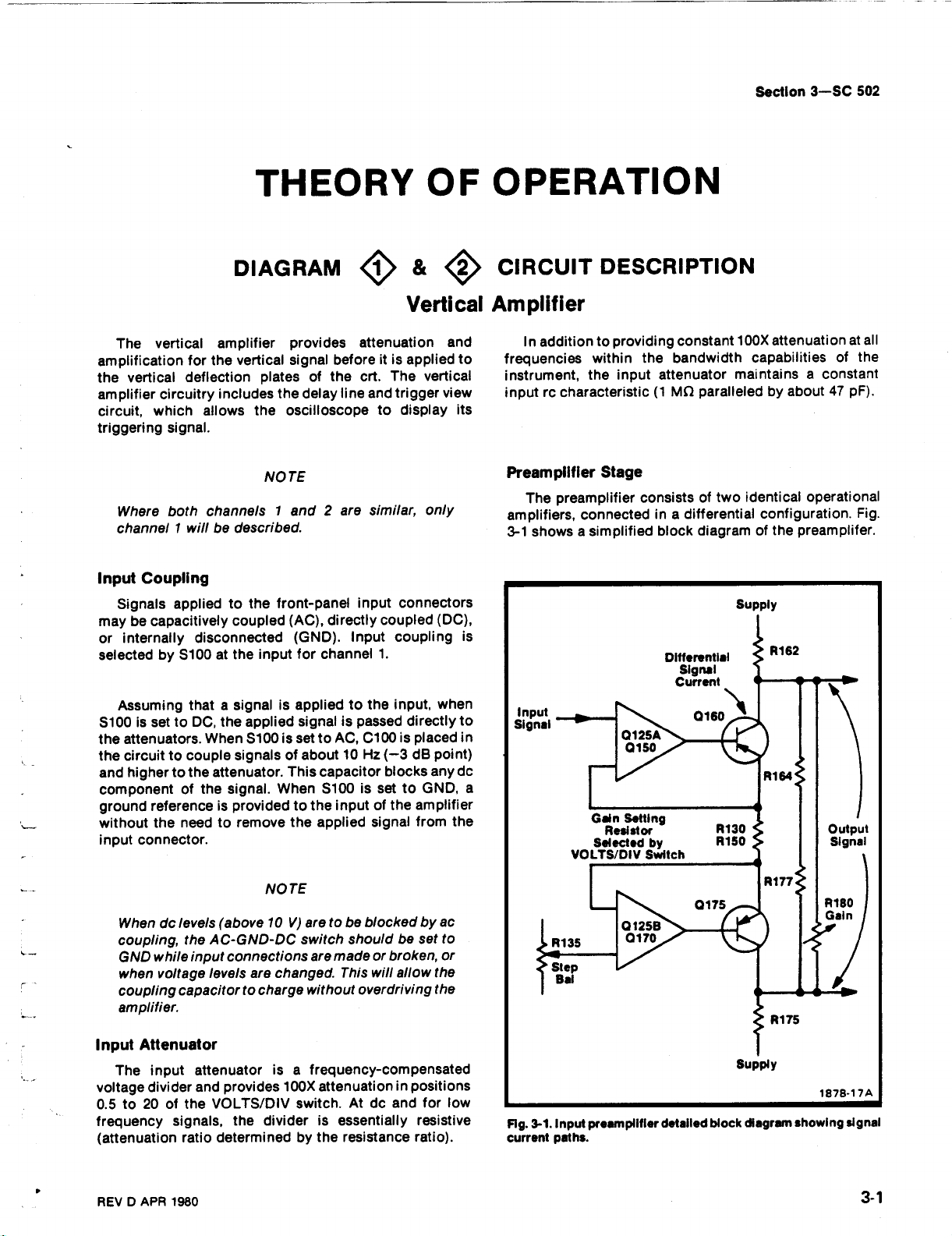
Section
3-SC
502
DIAGRAM
The
vertical
amplification
the
vertical
amplifier
circuit,
triggering
Input
maybecapacitively
or
selected
S100issettoDC,
the
the
and
component
ground
without the
input
circuitry
which
signal
Where
channel1willbedescribed
Signals applied
Assuming
both channels1and2are
Coupling
internally
by S100atthe
attenuators.When
circuittocouple
highertothe
referenceisprovidedtothe
connector
amplifier
for
the
vertical
deflection
includes
allows
.
to
coupled
disconnected
thatasignalisapplied to
the applied
signalsofabout
attenuator
signal.When
of
the
needtoremove
.
THEORY
provides
signal
beforeitis
platesofthe
the
delay
line
oscilloscope
the
TE
NO
.
the
front-panel
(AC),
directly
(GND).Input
input
for
channel1.
signalispassed
S100issettoAC,
.
This capacitorblocks
S100issettoGND,
inputofthe
the applied
O
F
&
O
O
Vertical
attenuation
crt.The
trigger
and
to
similar,
input
connectors
coupled
coupling
the
input,
C100
is
10Hz(-3dBpoint)
signal
applied
vertical
display
only
(DC),
when
directly
placed
any
amplifier
from
and
to
view
its
is
to
in
do
the
OPERATION
CIRCUIT
Amplifier
In
additiontoproviding
frequencies
instrument,
inputrccharacteristic(1MO
Preamplifier
The
amplifiers,
3-1
showsasimplified
a
within
the
preamplifier consists
connectedina
Gain
VOLTS/DIV
DESCRIPTION
constant
the
bandwidth
input
attenuator
Stage
differential
block
Differential
Signal
Current
Setting
Resistor
Selected by
Switch
100X
attenuation
capabilities
maintains a constant
paralleledbyabout47pF)
two
identical
of
configuration
the
diagram
Supply
of
preamplifer
at
of
operational
.
all
the
Fig
.
.
.
When
do
coupling,
GND
while
when
voltage
coupling
amplifier
Input
Attenuator
The
input attenuatorisa
voltage
0.5to20of
frequency
(attenuation
REVDAPR
divider
levels
the
AC-GND-DC
input
levels
capacitor
.
and
VOLTS/DIV
the
signals,
ratio
1980
NO
(above10V)
connections
are
changed
to
charge
provides
the
dividerisessentially
determined
TE
aretobe
switch
are
without
frequency-compensated
100X
switch.At do
by the
blockedbyac
shouldbeset
made
This
.
attenuationinpositions
broken,
or
will
overdriving
and
resistance
to
or
allowthe
the
for
resistive
ratio)
low
.
Fig.3-1.Input
current
paths
prearnpliflerdetailed
.
block
supply
diagrmn
1878-17A
showing
signal
Page 79

Theory
of
Operation-SC
502
The
operational
0150
and
0160
on
the other
follower
gain
the
paralleledbyR164,
pathinFig.3-1)
quiescently
thereisno
Whenasignal
currentisdeveloped
input
the stageisdeterminedbythe
of
two
sidesofthe
Correct
adjustmentofthe
balance
current
amplifiers
on
one
side,
side.0125A
output
to
R177,
.
the
through
appliedtothe gateof0125A
is
through
are
and
012513,
and
012513
transistors
amplifier,
and
R180
Step
two
sidesofthe
the
gain-setting
the
composed
0160
and
Bal
DIAGRAM
Gain
Stage
The
differential
0160
and
0175ispassed
and
0325totheoutput
are
0325
amplifier.0320
channel
and
Channel
The
gotothe
output
The
forward
positive
lows
operateina
describedindetail
Channel1MODE
switchtoCH1placesalowatpin3of
chop
flop
at
pin8of
The
The
0335
through
split
each
unused
also
switch
0345
.
Switch
outputsofthe
channel
amplifierisdetermined
MODE
biasing
logic
(0).Since
multivibrator
U360.The
U360,
remaining
signal
from
the
to
0415
equallybyR427-R425
sideofthe
channel
signal
developedatthe
through
amplifier
the lower
and
0325
loads
switch
switch
selected
which
the
different
similar
manner,
.
and
lowatthe
turningon0330,0335,
channel
channel1is
delay
line.The
and
0410,
delay
and
halfofa
provide
and
trigger
channel1and
where
S300
controls
transistors.Table
transistor
positionsofthe
only the
switch operation
lowatpins
a
CLR
switch
the
line.Summing
applying
emitter
channel
current
signal amplifier
channel2gain
signal that
the
.
the
willbeturned
2, 3,4and5of
inputofU360
transistors
passed
channel2signalispassed
currents
(Diagram
them
equallytoeach
0125A,
of
0170
and
provideavoltage
and
0175.Total
resistance
R162
(the
control,
amplifiersothat
gain-setting
between
and
signal
R135
resistor(s)
the
resistor
O
Vertical
collectors
followers
switch.0320
push-pull
channel
CH1position
.
Setting
U355
0415
through
are
4)
the
cascode
gaintodrivethe
goestothe
switch by
3-1
shows
on by
MODE
the
disabling
J-K
i
results
and
are biased
0330
summed
and
applied
currentofthe
0175
R175,
current
will
signal
CIRCUIT
of
0320
and
0340
stages
in
the
switch
will
be
MODE
the
flip-
nalow
0410
off
and
then
to
side
of
R130-R150.Conductionof0160
the
amountofthis
across
The
switch,
factors
balancedatequal
gain-setting
VOLTS/DIV
.
adjusting
while
R162
and
valueofR130-R150
S150,todetermine
To
minimize
are
rotating
trace
selected,
resistorsisnear zeroatall
switch.This
Step
Bal
the
DESCRIPTION
Amplifier
the delay
input
TRIGGER
MODE
CH1minus
outputiscontrolled
positionofthe
disconnected
U35513)
signalissupplied
12)
chop
channel
chop
.
chop-switching
.
MODE
to
inputofU360
line
supplies
current,
Swit
1
CH
CH
2
Chop
multivibration
producesa250
inputofU360
output
switch output
outputtothe blanking
Alternate
switch,
the clock
VIEW
CHANNEL
ch
2!Low
CH
MODE
from
theclock
to
transients
mode
a pulseatthe
(pin
causes
independent
switch
Low
High
12)
and
0175ischanged
current,
R175.The
potentials
control
VOLTS/DIV
U360
Pin 8
ground
via
and
operation.In
developing
outputisa
is
selected
the
gain
shiftasdifferent
0125A
the
theoutput
positions
Table
SWITCH
(0)
(1)
(0)
operation
the
by
switch
NAND
also
inputofU360isusedtoswitch the
between
inputofU360.The
the
and
that
so
do
balancingisachieved
R135
switch
of either
3-1
LOGICTABLE
Output
U360
Pin 6
High
Low
High
MODE
pins3and9of
and
the
kHz
square-wave
gate
the blanking
to
circuitisusedtoblank the
.
endofeach
channel
the output
push-pull
by the
.
vertical
012513
sources
thevoltageacross the
settingsofthe
fornotrace
from0.2Vto
amplifier
.
(1)
(0)
(1)
The
.
U355C
channels1and2.
the
with
the
Level
U355
Pin 12
High
(1)Low(0)
High
(1)
Low
(0)
chop
switch.In
multivibrator
to
ALT
positionofthe
sweepissupplied
pulse
switchtochange
voltage
signal
VOLTS/DIV
deflection
aredo
movement
1mV.
aconstant
MODE
U355
Pin 13
High
(1)
(1)
High
multivibrator
the
CHOP
U355
are
(U355A-
signal.This
the clock
circuit.The
to
the
(pin
The
clock
the
by
.
by
or
3-
2
REVBAPR
1980
Page 80

input
channel
endofeach
the
Trigger
Trigger
signal
from
Delay
Line
Delay
for
the
vertical signal,
circuits
reaches
the
originated
ing
timetoinitiateasweep
the
instrument
.
thatisconnectedtothe output
sweep
.
Amplifier
amplifier
the
0340
vertical
and
0345
preamplifier
DIAGRAM
Line
DL400
vertical
display
the
trigger
provides
which
deflection
pulse
the
approximately
allows
before
plates
leading
when
amplifies
and
suppliesitto
Vertical
140nsdelay
the
sweep
the
vertical
the
crt.This
of
edgeofthe
using
internal trigger-
amplifier
the
4O
at
output
the
CIRCUIT
appropriate
usedasatriggering
The
channel
auxiliary
an
connectionsofthe
DESCRIPTION
Amplifier&Trigger
0470.R461,
generator
signal
lets
signal
that
controlling
of
Q465
networks
rc
optimize
high-frequency
amplifier
the
and
amplifier
speed
signal
1
trigger
trigger
amplifier
amplifier
View
R460
and
R470
signal
degeneration
Variable
0460
.
provide
high-frequency
frequencyresponse
peaking
.
TheoryofOperation-SC
trigger pickoff
sourceforthat
also
supplies
.
set
the
gainofthe stage
between
capacitor
coils
to
C474
provide
.
circuit
vertical
the
the
and
compensation
L470
and
502
to be
channel
signal to
by
emitters
the
series
to
L475
are
additional
.
Output
amplifiertoprovidealow
terminatethe delay
the delay
amplifier
Q455
Q465
Amplifier
and
Q450
line
and
and
0460compose
that
drives
are
line.It
the
following
the output
connected
input
also
an emitter-coupled
as a
impedance
provides
stages
power
amplifiers
common-base
to
isolation
.
properly
between
push-pull
Q475
and
Trigger
output
the
switchisdepressed, the
channelissummed
applied
triggering
delay
displayed as the
View
Trigger view
signal
from
TRIGGER
each
to
signalisapplied
line.The
amplifier
the
VIEW
switch.When
and
sideofthe
trigger
vertical
0440
trigger
comparator
vertical
equallybyR427-R425
split
delay
differentially
signalisnow
signal
and
signal
line.At
.
the
0435
and
TRIGGER
from
the
toeach
amplified
amplify
supplyitto
each
vertical
same
time
sideofthe
the
VIEW
and
the
and
REV
B
APR
1980
3-3
Page 81

Theory
The
also
level
trigger
a
sampleofthe
sampleofthe
The
the
either
deflection
EXT
voltage applied
this circuit
Trigger
The
appliedtothegate
Q520A
signal
provides
and
current
temperature
voltage-to-current
match
from
horizontal
the
in
.
Trigger
The
the
emitterofcommon
input
COUPLING
0510.The
(0555,
comparator
trigger
R560.If
higher,
is
Q580ishigh.The
0575islower
of
the
U595
Trigger
AUTO
Operation-SC
of
trigger
selects
necessarytomatch
signals.Input
trigger
sweep
from
TRIG
EXT
andalow
the
that of
common
front-panel
SOURCE
impedance.The
trigger
andtothe
trigger
pickoff
and
amplifies
signal
power
generator
generator.These
the
internal
system, an
input
connector, or a
tothe
to select
Pickoff
TRIG
which
provides
isolation
base
of
source
compensation
the other
base
amplifier.R518
EXT
Generator
outputofthe
pushbutton
pushbutton
outputofQ510
0550
Q565,
(Q580
comparatorisfrom
the
voltageatthe
current
(the
comparator
trigger
Level
mode
502
DIAGRAM
Trigger
selects
signal
applied
line
instrument.Controls areprovided
trigger
signal
field
of
impedancetothe
between
Q525
for
converter
amplifier
SOURCE
trigger
base
and
and
flows
oppositeistrueifthe
collector
Control.The
pushbutton
the
internal
the
external
the
current
for
the
Channel
to
voltageoran
produces
trigger
trigger
external
from
a high
as
Q520A.Q520B
triggering
amplifier
outputof0500
Q575).The
trigger
through
view
signal
signal
sample
level,
thefront-panel
effect
transistor
input
the
Ext Horiz
wellasactingasa
for
0520A.0525
whose
0530
supplies
pushbuttonisnot
pickoff,
switches,isappliedtothe
switches
goes
to
Q560)
and
the
triggering
comparator
0575
0580islow).Both
of
are
suppliedtogate generator
amplifier
triggering
pushed
trigger
trigger
levelofthe
trigger pickoffiseither
1,orChannel2,a
external
trigger
slope,
current
0500
the
pulsestostart
pulses
from
connected
the
of
and
sourcefollower
impedance
baseof0525
Bal
control,
also
output
sources.The
is
supplied
for
whichisselected
to provide a
passes
emitter
to
trigger
alsotothe
other input
LEVEL
and
the
base
Q440
level,
in,iscontrolled
O5
CIRCUIT
Pickoff
signal.It
signal
tothe
internal
signal
are derived
the
vertical
to the
power
line
coupling
connector
current
0525when
through
level
baseofQ575
collector
and
for
0520B
.
R535
constant
provides
forms
output
to the
pushed
follower
circuit
trigger
to
control,
voltage
outputs
0435
with the
.
the
will
low
the
the
.
by
in
of
of
.
DESCRIPTION
Generator
and
by the
basesof0555
emitter
and
signal.C567ischargedina
negative
capacitors,
the
0550
tobeadjusted
the
signal
control
is
the output
waveform
pin1connectedtoground(+
waveform
a
(output)torise
about
conditions.The
are
SLOPE)
negative
signal
that
(about+4.2
gate generator
the
availableatthe
drivers
24Bofthe
enablesline
Gate
connector.0625
to selectaninternal
sweep
Auxiliary
suppliedtocommon
input
connectedtopin
triggering
Assume
triggering
most
With
Gate
within
Ifitis
A
a
follower
charge
after
holdoff
sampleofthe
C552tothe
levelofthe
C552-C567,
and
Q560.This
negative
.
the
AUTO
limits
generator,
signals
whichisused
(3 to4V)
3.2V.Pin 14isnegative
about20mV
causes
going
from
the
completionofthe
V) during the
time.The
U600B
desiredtoover-ride
rear
and
Ext
generator
Trigger
impedance
signal,
and
+
input
Q555,
LEVEL
between
and
pushbutton
are
setbyR556-R558
from
about4.1Vand
to
output gate
gate outputatpins3and4when
a
and
sweep
until
rear
and
interface
receiv er
Gate
and
.
and
28Bonthe
applied
0565
.
signal.This
causes
peak
input
set
control
allows
the
two
most
integrated
the
for
sweep
theICinput
on
of
pin 14
generatorissupplied
holdoff
these
pins
triggered
interface
U6000
.
connectorisgrounded.This
U600Atosupply
input
signals
0630
external
or
Amplifier
channel1preamplifier
base
amplifier
isolation.The
simultaneouslytothe
signal,
the
emitter
positive
similar
signal.The
the
voltage
(R560)
the
triggering
voltage
positive
out,
the
and
circuit
trigger
each
sweep,
control
comparatortoa
generator
SLOPE),
(pin13)
pin 4
going under
occurs
positive
when
other
pins6and
time.This
droptoabout3.2Vafter
gate
connector
the gate
from
the
gate as the
0540
rear
interface
coupledthrough
voltagetorise
levelofthe
mannertothe
peak-sensing
levels
applied
via
emitter
levels
peaksofthe
triggering
(IC),
(output) to
.
Floating
going.The
outputofU595,
the
the
diode
outputof0540
followers
LEVEL
representing
R568-R569
U595
control
a
positive
causes
the
pins
13
to
10
inhibits
and
holdoff
through
substitute
rear
interface
switch
inputtothe
output
to provide a
connector
input
peak
to
control
trigger
LEVEL
.
converts
gate
.
With
going
pin
drop
to
above
and
14
pin1(-
pin13is
holdoff
U595
so
are
high
the
are
line
pin
Ext
used
signal
low
.
3
is
is
3-4
REVC
APR
1980
Page 82

DIAGRAM
Sweep
Sweep
sweep
of
gates
determined
negative-going
wave
the
from
positive.Eitherapositive signalatthe
negative
collector
flow
supplies
allows
to+5V
AUTO
armed,
READY
occurs
limits
the
through
amplifier
RESET
buttonisheldin(closed)toprevent
triggering
Control
U650,
with
additional external
generator.In
U650isgrounded
from
the
trigger
byR664
square-wave.This
from
pin3drives
sweep
operatesinthe
the
trigger
signalatthe
currentofthe constant
through
In
the
When
voltageisabout
0660,
currenttounblank
the
sweep
single
sweep
and
pin19mustbeungrounded
trigger
pins
indicatortolight.This
when
the
button.The
mode
7
and
the
LED
current
pin18is
at
action
SECOND/DIV
the
sweepinthe
the
automatic
If
pin
.
and
generator
thus
generatortorun
11 of
sweepisin
about+4V,the
0V,the
the
1ofU650
generator
C662,
circuitryinU650
the
base
triggered
drives
baseof0660
turning
the
crt,
mode,
pin12of
pushbutton.When
U650
actionatpins7and11also
the
.
sweepisenabled.This
anodeofCR649
switch
or,
sweepisdisabled
single
circuity,
triggering
foraperiodoftime
negative-going
Q660
of
modeapositive
will
current
off
0670.Q660turning
while
.
are
low,
triggered
sweep
through
transientsfrom
sweep
O6
CIRCUIT
Control
controls
mode,
receivesnotrigger
negative.When
the
base
baseof0670
cause
source
turning
U650isconnected
releasing
by
the
causing
mode.R643
is
disabled.When
from
the
CR648
when
the
mode
the
pin
outputs
square-
pulse
of
0670
or
the
entire
Q665
0670
the
sweep
TRIG'D
occurs
horizontal
and
the
RESET
falsely
.
19
to
on
off
is
DESCRIPTION
and
Generator
Sweep
off.When
off.The
timing
a
amplifier
ramp
determinedbythetiming
tion,
a
current
exceeds
forcedtoretrace.As
Q680
equal the
integrator
The
0690B
the
connector
(Schematic
16
of
circuit
channel
each
Generator
The
sweep
current
capacitor
(0690A,
.
The
untilitreaches approximately+6.9
At
the
through
the
and
Swp
Offset
so
The
outputofthe
horizontal
through
the
holdoff,
throughcomparator
switch
sweep
rampisgenerated
0670isoff,
from
the
due
0690B,
positive
endofthe
timing
CR675
timing
output
the
through
3),
comparator
.
going
sweep,
Q675
resistor
turnon.
resistor
0Vuntil
to
control,
gateofQ690A
sweep
preamplifier,
emitter
sweep
and
the
change
to
HORIZONTAL
Theory
transistors
timing
to
the
and
ramp
resistor
0670isturned
and
0685
current,
the
sweep
This
causes
current,
the
R681
adjusts
is
generator
pin
followers
control integrated
0310
and
channel
0310
the
input
Operation-SC
of
during the time
0685
resistor
actionofthe
Q695)
creating
now
and
capacitor
When
.
the
ramp
the
thus
startofthe
the
at0V
.
goesto:
18Aofthe
0315
switch
and
channelatthe
AMPLIFIER
0670
and
nowflows
runs
V
.
the
sweep
drops
0685
clamping
drain
0310
circuit
to signal
alternate
0315tocause
will
0675
intothe
operational
the
sweep
upata
combina-
forcing
on
0685
current
ramp
below0V,
current
next
sweep
current
input
the
interface
rear
and
U650
the
end
502
is
be
rate
is
to
the
.
of
of
0300
pin
start
mode
the
of
A
holdoff
connectstothe
tionofsweep
a
single
peakofthe
circuitstoreturn
before
the
connectedtopin8of
They
are
SECONDS/DIV
U650
reaches
0655
-5Vsupply
REVBAPR
waveform
trigger
gating
sweep
has
sweep
next
sweep
determined
switch.Holdoff
about2.4V.
actsasan
.
1980
ramp.Itisnecessary
is
availableatpin
generator
waveforms
occurred.Holdoff time beginsatthe
completely
starts.The
U650
by the
emitter
preventing
during
to quiescent
capacitors
determine
sweep
time
follower
holdoff
toallowthesweep
the
rate
starts
andaregulator
17
which
the
genera-
times
after
conditions
and
resistors
holdoff
settingofthe
when
time
pin 16
for
.
of
a
Preamplifier
When
the
position,
amplified
provides
suppliedtothe
The
MAG
resistor.The
positions
0720
reaching
outputofthe
the
low
gainof0700
switch
also
prevent the
to
the output
In
the
AMP
by
SECONDS/DIV
sweep
external horizontal
ramp
common
input
impedanceand
inputofthe
determined
is
which
controls
SECONDS/DIV
forward
amplifier
positionofthe
switchisinasweep
from
base
horizontal
the
switch
biases
external horizontal
.
SECONDS/DIV
the
sweep
amplifier
isolation
output
bythe
positionoftheSWP
sizeofthe
in
the
0715
and
signal
from
rate
generator
0700,
reverse biases
.Itis
amplifier
collector
sweep
signal
switch,
the
trigger
which
then
rate
from
the
3-
is
.
5
Page 83

TheoryofOperation-SC
pickoff
providesalow
signal.The
collector
control
AMP
amplifiedbycommon
is
input
gainof0720
resistor,
R723
and
R725.The
position
also
impedance
which
causes
502
base
amplifier
and
isolation
determinedbythe
is
includes
SECONDS/DIV
Q710tobe
the Ext Horiz
forward
0720.0720
fortheinput
sizeofthe
Gain
in
switch
biased
the
and
0700tobe
reaching
The
POSITION
current
current
source
being
reversebiasedtoprevent
the output
transistor
fedtothe
amplifier
controlisconnected
.
0730,
inputofthe
whose
the
output
output
sweep
to
rampfrom
the
base
adjusts
amplifier
of
the
.
Output
preamplifierisapplied
comprise
current
the
Centering
for
differential
Sweep
horizontal
compensation
Transistors
are
connected
Amplifier.The
emitter
an
source
control,
unbalanceinthe
Gain
control,
amplifier.R750
for
Q775-0780-0785and
as
coupled
R760
the
two
DIAGRAM
output
tothe
base
paraphase
for
the
paraphase
providesameans
R770
sets
and
paraphase
separate
DIAGRAM
O7CIRCUIT
Horizontal
of
the
0745.0745
of
amplifier.0755
amplifier.The
of
amplifierorcrt,
the
overall
R764
amplifier
current-driven
Z-Axis
gainofthe
provide thermal
stage
0770-0795-0790
Amplifier
horizontal
and
Q765
correcting
while
the
.
feedback
CIRCUIT
Amplifier
amplifiers.Input
amplifier)isan
positive-going
is
right
negative-going
output
input
networks
C776,
amplifier
and
DESCRIPTION
signals,
output
Negative
amplifier)
signal
feedbackisprovided
transistors
transistors
C773-R773and C785-R789.Capacitors
and
C791
response
DESCRIPTION
Crt
Circuit
transistor
NPN
response
0780-0785-0795-0790
0775
are
speed-up
fast
to
0775
transistor
while
input
a
PNP
is
.
and
0770
capacitors
changes
for
(in
the
better
transistor
transistor
the
from
to
through
to
.
left
output
response
Q770
(in
for
better
collectors
the
base
feedback
C775,
improve
to
the
of
of
the
The
crt
provides
cathode-ray
amplifier
sion,
Z-Axis
feedback
amplifier
pathisfrom
to
are
amplifier
consuming
pull-up
sistor
amplifier
intensity
3-
since
The
the
summing
connected
6
the
Amplifier
Z-Axis
consistsofQ835,
transistor
for
circuit
produces
control
tube
(crt).The
circuits
operational
that
provides
level
are
they
set
amplifierisa
0845-0840
the
pointatthe
as a
providesafast
minimum
and
the
amplifier
through
the
high
circuits
the
the
necessaryfor
Z-Axis
included
amplifier
collector-coupled
quiescent power,
0840
the
with
intensityofthe
current
with
0845,
and
collectors
baseof0835
linear
acts as
.
The
output voltage
drive
signal to
control-grid
voltage
amplifier
the
potentials
operation
and
crt
circuit
crt
display
driven,
voltage
a
0840.Thefeedback
through
output
the
output.The
C834-R834
.
0845
complementary
signal
0845
acts
pull-down
control
.
supply
and
of
Blanking
discus-
.
shunt-
and
0840
while
as the
tran-
from
the
the
the
crt
The
output voltage
determinedbythe
to the
voltage
(baseof0835).The
by
the
INTENSITY
current
Z-Axis
the
and
0830
signal
setting
voltage
levelatthe
Blanking
A
combinationoffour
output
unblanking,
sweep
ing
and
and
0805
levelatthe
input
current
control
limiting resistor
amplifierincaseofa
formacomparator
the
level
currentofthe
intensify
0830
at
baseof0825
Amplifier
form a
comparator
voltage
current
from
and
R841
reference
base
blanking
horizontal
from
pin
levelofthe
across
drop
summing
combinationoftwo
a
sweep
mustbemore
.
different
19Bofthe
point
through
blanking.CR841
actasa
level.To
circuit
protection
high-voltage
the
with
input
amplifier.These
amplifier
with
Z-Axis
R834
unblank
rear
amplifier
R834inreference
amplifier
forthe
is
determined
sources,
circuit
short.0825
sweep
positive
signals control
mode,
the
blanking
the
crt,
than the
signals
blank-
chop
interface.0800
baseof0805
REVCAPR
is
and
for
the
the
are
1980
:
Page 84

Theory
Operation-SC
of
502
setatabout
negative
more
amplifier
All
the
base
amplifier
pedance
bias-setting
proximately5mA
while
the
about1mA
0820isabout0.3
High-Voltage
High-Voltage
their
with
and
the
T850
allows
sinusoidally
saturating
High-Voltage
following
sampling
and
comparingittoa+20.0V
junctionofR893C-R893D
nominally0V.If
negative,
becomes
U860
U860
to
resultsinincreasedcharging
cause
0855
increasing
begins
providing
ensure
its
most
C854ischarging,
most
negative
CR855
0860.0860's
0855,
thus
turning
with
its
the
energy
via
0850
has
been
base-emitter,
positive
+3.7V.The
than+3.7Vbeforeitcontrols
output
.
controlling
and
isolation
transistor
front-panel
through
associated
drivetoenergize
T800
while
switches
discussion
the-2kV
the
junction
positive.The
go
to
the
to
conduct,
positive
that
saturation
negative
and
turningonCR853
causing
offof0855isspeeded
one-turn
stored
and
CR850.0850
completely discharged.With0V
the
than the
input
0815,
which
from
0820.A
through
set
the
transistor
mA,
the
Regulator
Regulator.0860, 0855,
components
primary
allowing
.
Regulation.Refer
.
Regulation
across voltage
the
more
conduct
average
voltage.Duringthe
voltage,
conduction
winding.The
within
primaryofT800
input
kV
-2
R893C-R893D
of
positive,
outputofU860
longer
currenttoT800
T850
feedback
will
continue
then
the
at
C854
its
collectortogo
the
supply
input
intensify
signals
intensity
crt
winding
pass
providesalow
the
impedance-matching
0820
turns the
.Ifthe
beam
a resonant
0855
and
reference
wellaspin3of
as
supply should
causing
current
during
allows
from
its
time pin 5ofT800isat
starts
discharging,
to
provide
reduces
up by
current
now
coil
remains
voltage
signal
through
current
causes
willbeintensified
provide
(pins4and5)to
to
is
divider
ittosaturate
until
conduction
the
turnedonuntil
may
flow
crt
current
0850
the
transformer
Q850
to
Fig.3-2
accomplished
R893C-R893D
supply
become
and
hence
theoutput
going
for
C857,
each
cycle,
and
T850
one-turn
pin5of
base
base
more
positive
the
action
through
flows
through
across
now
.
must
the
blanking
common
input
of
beam
current
a
through
and
regulation
function
during
U860,
pin3of
(pin6)of
positive
which
thereby
.As0855
winding
T800
of
0855,
cuttingoff
current
current
of
T850
swing
im-
and
apoff,
U860
T800
move
the
by
.
The
less
will
while
is at
The
.
T850
and
T800
T850
0850
more
go
of
.
as
is
to
its
to
of
Fig.3-2
high-voltage regulator
.
sinusoidally,
Duringthe
charging
with
again
on, the reference supply voltage
positive
(whichiscontrolledbyR860).Oncethe
becomes
the
short
pin
reference
IfaT800
will
divider
will
0860
High-Voltage
and
voltage
supplied
the
about3.3kVpeak
cathodeisalso
ding
and
Time
relationshipofwaveformsatthree
.
high
The
C857
voltageoftheone-turn
cause
slowly,
more
reference
should
F11
will
voltage
secondary
blow
to
or
turn
CR856
.
The
secondary
positive
for
Positive
by voltage
inputofU850
CR881
.
supplies
of
0
thus
setting
time
that
0855
a
voltage
to
0855toconduct.Initially
depending
positive
supplyisheldasa
occurtothe
move
toward
and
winding
protect
the
regulator
onto
Outputs
windingofT800
accelerating
the
control
accelerating
tripler
from
.
The
obtained
half-wave
the-2kVtothe
T800
than
consequently
Q855.If
remove
grid
voltage
causes
conditionsfor
not
was
upon
T800
circuit
potential
and
voltage
U850.The
the
from
rectifies
conducting,
level
which
feedback
the
+20V,CR862
constant
secondary,
zero,
thereby
short
remainsforati
the
R893C-R893D
should
the
base
heater
for
secondary
T800
for
the
the
the transformer output
cathode
crt
pointsinthe
its
voltages
conduction
when
winding
instrument
at
allowed
is
chargingrateofC870
voltage
conducts
+20.6V.If
the
reducing the
thetransformer
fail
R855
drive
from
the
voltage
the
crt
applied
crt
directly
secondary
.
the
crt,
provides
for
T800
to
U860
combined
T850
of
to
pin
at
voltage
me,
voltage
and
0855
negative
the
for
the
screen
voltage
winding
heated
vary
again
was
turn
move
drive
F800
R857
bias
crt
win-
.
will
F11
and
a
at
.
via
.
is
to
is
@
MAY
1980
3-7
Page 85

TheoryofOperation-SC
Diodes
control
this
CR879
T800
control
bias voltage,
Axis
CR882isset
restorer
across
anodeofCR882
CRT
previously,
CR885
voltage
supplyissetbythe
and
CR882
secondary,
grid.CR879
depending
amplifier.The
by
and
CR884asa
R888
Control
In
addition
front-panel
equaltothe
CR884
and
for
the
clip
determine
to
limits
positive
the
Beam
.
Circuits
to
the
502
providethe
crt
control
Beam
the
upon
rectifier.This
INTENSITY
FOCUS
grid.The
adjustment
crt
grid bias
the
the
negative
the
output
clipping
adjustment.CR885
peak-to-peak
and
DIAGRAM
Low
Voltage
rectified
voltage
operating
excursion
voltage
levelatthe
resultsinadolevel
excursionatthe
control
internal
negative
level
output
R873.Diodes
from
levelatthe
of
cathode
as a
acts
discussed
astigmatism
9O
Power
of
the
the
of
the
Z-
of
de
CIRCUIT
Supplies
.
Geom
have been
crt
display.FOCUS
voltage
for
the
third
R899.In
both
the
adjustment
deflection
adjustment
coil
L895toalign
lines
.
FOCUS
controls
timum
correct
voltage
control
shape,
provide the proper
crt
horizontal
geometryofthe
permits
rotation
graticule
DESCRIPTION
and
incorporated
for
the
second
anodeisobtainedbyadjusting
ordertoobtain
and
electrostatic
R897
varies
plate
display.The
of
the
the
for
arrivingatan op-
control
Astic
shieldstocontrol
trace
do
R894
anodeinthe
optimum
controls
lens
configurationinthe
the
positive
rotation
current
display
through
with
Calibrator
provides
crt
.
size
spot
are
adj
levelonthe
the
control,
the
horizontal
Proper
Astig
and
usted
overall
R895,
beam-
the
to
-20VSupply
Power
for
the
-20Vregulatorissupplied
TM
500
Series
Power
Module
ly.The
operational
consistingof0960
in
R949,
R947
operational
about2.9
voltageisestablishedbycomparing
negative
the
negative
conduction
transistor to
power
asanoperational
backtoits
eventofa
current
biases
+20VSupply
Power
position
regulator
amplifier
the
power
module.The
R947
and
and
R945
amplifier.The
times
input
(pin2)of
and
module
negative
current
through
0960
Off
the
applies
input
positive
of
correct
off,
Circuit for
positive
The-20Vand
Placing
for
U950,
and
R945.R949isthe input
are the
by R947 (-20VAdjust)
(pin3).
inputstoU950
0960
for
NPN
series
amplifier
input.0955
overload.The
R943)
shutting
+20Vsupplies
MODE
+11.5V
the
-20Vsupply
and
the
NPN
gain
feedback
gainofthe
with
U950
Any
and
power
the output
pass
whose
will
cause
the
-20
switch
to the
-33
.5
transistor that
of
the
differences
transistor
protects
-20
are
V
and
(S300)inthe
negative
from
V
unregulated
consists
the
series
pass
located
is
the
amplifierisset
resistor,
resistors
amplifierisset
the
voltage
causeachange
module
error.0960
outputisconnected
the
overload
0955toturn
V
supply
similarinoperation
+20
inputofU930
for
The
.
voltageatthe
reference
between
series
and
are
connected
supplyinthe
(increase
on,
off
.
V
Supplies
PWR
the
supp-
stage
by
while
the
supply
the
in
the
pass
the
which
OFF
and
of
to
to
the outputofthe
0930
+11
0950
positive
-20
+5VSupply
at
TM
ly.The
operational
0970.The
the
supply
the
in
.
positive
positive
of
error
overload.The
will
the
the
baseof0930.The
+20
on,
pulling
At the
same
time
applied
.5Vis
whichinturn
inputofU950
V
regulatortonear0V
Power
Ifanover-voltage
open,
to
for
the+5V
500
Series
Power
regulator
amplifier
amplifierisconnected
feedback
negative
Darlington
.
0965
cause
+5Vsupply
Zener
resistor
voltageisestablishedbycomparing
inputofU960
input.Any
inputsofU960
transistor
protects
overload
0965
to
off
excessive
an
diode
+11
.5
V
regulator,
the
supply
+11.5Visappliedto0930
totheemitterofcommon
appliesaslightly
for
differences
the
turn
.
VR969
output
This
reduces
.
.
regulatorissupplied
Module
for
condition
amountofvoltage
+11.5V
the
+5Vsupply
U960
and
the
with
causesachangeinthe
0970
supplyinthe eventofa
(increase
on,
which
NOTE
which
V
appliedtoU930
while
the
down
positive
the outputofthe
unregulated
series
for
unity
operational
the
voltage
between
to
in
biases
causes
may
the
correct
current
0970
willbeapplied
damage
reduces
+11.5V
to
base
voltagetothe
pass
gain.R969
amplifier.The
the
referenceatthe
for
through
fuse
the
turns
ground
and
0930,
amplifier
from
supp-
consists
transistor
voltage
negative
conduction
the output
current
R982)
off,
shutting
F970
diode
.
to
.
the
of
is
at
and
3-
MAY
8
1980
Page 86

Une
Trigger
A
line-frequency
of
TM
500
Series
uatedbyR905,
source
Calibrator
their
wave
the
for
The
Calibrator
associated
output with
power-line
the
signalisobtained
PowerModule
R907,
and
R909toprovide a
time-base
passive
accurate
frequency.This
circuit
.
composed
components
amplitude
from
the
secondary
transformer
of
producesasquare-
andata
outputisavailableatthe
and
line-trigger
0910,0900,
rateoftwice
atten-
and
TheoryofOperation-SC
front
calibrator
peak)
The
receivesapulsatingdovoltage
CR900-CR902
switching
switched
through
sistor
calibrator
jackonthe
square-wave
resistive-capacitive
signal
on
R915
through
or
test
and
for
and
offattwice
alternately
is
signal
voltage
Q910
CR915
.
panel as a0.6V(ground
.
networkatthe
produces
and
Q900.As0910isalternately
the
switched
and
from
a
line
R917,
nearly
baseof0900
full-wave
symmetrical
frequency,
through
producing
502
rectifier
current
the
tran-
the
to
@MAY
1980
3-
9
Page 87

Section
4-SC
502
CALIBRATION
PERFORMANCE
Introduction
This
procedurechecks
theSC502
section.If
given
procedure
be
usedbyan
acceptability
The
onlyiftheSC502isadjusted
TM
500
module
Function 5Hzto
generator
Time-mark
generator
Calibration
generator 100V;
Leveled
wave
Input
normalizer
Termination
Coaxial
cable inch;connectors,
Dual
cable
Adapter
that
appearinthe
the instrument
in
this
performance
shouldbeperformed.This
incoming
performance
of
electrical
Description
power
sine
generator
input
characteristicsinthis
the
electrical
Specification
failstomeet
inspection
.
an
at
Performance
5
0.2s to 5
Amplitude
accuracy,±0.25%
output,
1
50
47pF
impedance,
within2%;
Impedance,
Bnc
connectors
Bnc-to-pin
squarewave
kHz
.
kHz
to
and
femaleto2
check, the
facility
ambienttemperature
LIST
kHz
.
nsin1, 2,5sequence
calibration,5mV
15
MHz
M11
1
50R;
connectors,
50R;
.
jack
characteristics
portion
requirements
the
adjustment
procedurecan
determine
to
section
.
.
bnc
.
are
OFTEST
Requirements
into1MA
approximately
at
accuracy,
bnc
length,
bnc
42
.
male
of
this
of
also
valid
of
Table
EQUIPMENT
.
to
.
PROCEDURE
CHECK
+20°Cto+300C
of0°Cto+50°C.
Tolerances
procedure
include
Test
Equipment
Belowisa
as
specified.Other
suitable
4-1
REQUIREMENTS
All
steps
Frequency
Sweep
Vertical
accuracy
;
Bandwidth,
sensitivity&range,
&
X-Y
Vertical
input
.
Output
for
signal
Provides
interconnection
X-Y
phasing
Calibrator
that
apply
test
equipment
listofequipment
.
Applications
.
response
rate
accuracy
deflection
.
trigger
phasing
.
amplifier
termination
generator
signal
.
.
and
operatedatan
are
specifiedin
the instrument
to
error
Required
equipment
.
.
.
.
ambient
this
performance
under
test
.
requiredtoverify
may
TEKTRONIX
TM
TEKTRONIX
Function
TEKTRONIX
Time
TEKTRONIX
Calibration
TEKTRONIX
Leveled
Generator'
Tektronix
067-0541-00
Tektronix
011-0049-01
Tektronix
012-0482-00
Tektronix
067-0525-01
Tektronix
013-0084-01
substituted
be
Example
TM
504,TM506
FG
Generator'
TG
Mark
Generator'
PG
Generator'
SG
Sine-Wave
.
partno.
.
partno.
.
partno.
.
partno.
.
partno.
.
temperature
check
anddonot
operation
when
503,
.
503
.
501
.
506
.
503
REV
APR
198
1
41
Page 88

Calibration
Performance
Procedure-SC
Check
Description
Termination
voltmeter
DC
Plug-in
extension
10X
attenuator
RequiresTM500-series
Preliminary
CH
Control
1
VOLTS/DIV
CAL
DC-GND-AC
CH
2
VOLTS/DIV
CAL
DC-GND-AC
SECONDS/DIV
PULL
X10
HORIZ
CAL
TRIGGERING
AUTO
COUPL
SOURCE
SLOPE
LEVEL
MODE
INTEN
FOCUS
POSITION
CH
CH
POSITION
SINGLE
1.Check
To
+350C)
(vertical)
1
2
(horizontal)
SWP
the
Vertical
DC-GND-AC
VOLTS/DIV
CH
a.Connect
connector
(CH1and
2)
the
calibration
througha50ncoaxial
502
Performance
Impedance,
within2%;
600
n
;
connectors,
0-200V,accuracy,0.1%
50O.
power
module
.
Settings
1
cw
(detent)
GND
1
cw
(detent)
GND
.2
m
MAG-
pushed
in-cw
(detent)
i
n
DC
(all
buttons
CH1
+
-
midrange
CH
1
normal
sharp
Q=
z
brightness
trace
midrange
midrange
midrange
out
Deflection
Accuracy
DC
20
generatortotheCH1
cable
.
Table
Requirements
accuracy,
bnc
.
.
out)
(+15°C
input
41
(cont)
Low
response
Power
checks
All
steps
Vertical
response
b.Adjust
five
graticule divisions are
c.Check-that
d.Check-readout
listedinTable
When
bient
accuracy
VOLTS/DIV
50
20
10m
Applications
frequency
.
supply
.
.
frequency
.
the
generator
4-2
.
checking
temperature
byan
VERTICAL
Generator
Setting
10
5
2
1
.5
.2
.1 .5
m
m
_
m
5
50
2m
1
m
Tektronix
011-0092-00
TEKTRONIX
Tektronix
067-0645-02
Tektronix
011-0059-02
variable
displayedonthe
the readout
error
for
NO
TE
the
deflection
range
of 0°Cto
additional1.0%
Table
42
DEFLECTION
AND
TOLERANCE
50
V 5
20
V
10V
5V 5
2V
1
V 5
V 5
.2
V 4
.1
V 5
mV
20mV
10
mV
mV
5
Example
partno.
.
partno.
.
partno.
.
control
errorisless
the
following
accuracy
+50°C,derate
.
ACCURACY
Display
4
5
4
5
4
5
5
DM
501A
until
crt
.
than2.0%
atanam-
Tolerance
2
!
2
2
2
-
-
2.0%
I
2
2
2
2
2.0%
5
5
.
exactly
.
settings
the
.0%
.0%
.0%
.0%
.0%
.0%
_
.0%
.0%
_
%
.0%
.0%
_
4-2
REVDAPR
1980
Page 89

e.Repeat
f.Disconnect
controlstothe
2.Check
DC-GND-AC
VOLTS/DIV
CH
SECONDS/DIV
SOURCE
a.Connecta50
generator output
connector
b.Adjust the
divisionsofdisplay
partsathroughdforCH2
preliminary
the
Vertical
(CH1and
2)
.
all
cables
and
settings
Deflection
DC
lo
1
p
EXT
A
coaxial
connectortothe
generator
.
cable
output
return
.
Variable
m
from
SC
for
.
the
front-panel
the
calibration
502
CH1input
five
Range
graticule
b.Adjust
graticule divisions
c.Set the generator
thefrequency
4.2major
d.Check-that
generatorisequal
e.Change
f.Connect
input
50
kHz
g.Repeat
h
.Leave
the
variable
divisionsinamplitude
the
the
connector
and
set
the
partscanddto
all
controls
generator
.
frequency
until
the
to or
greater
MODE
sine-wave
and
return
amplitude
and
Calibration
foracrt
thedisplayed
frequency
switchtoCH2.
the
check
connections
Procedure-SC
Performance
displayofexactly
to 15
.
readout from the
than15MHz
generator output
generator
for six
graticule
theCH2
MHz
signal
frequency
for
the
Check
adjust
and
is at
least
.
CH
to
divisions
bandwidth
next step
502
six
2
to
.
.
.
c.Rotate
displayed
d
clockwise
e.Check-that
divisions
f.Connect
connector
g.Disconnect
controlstothe
3.Check
20
signal
Turn
CH
the
position
in
amplitude
and
the
2)
.
V/div)
VOLTS/DIV
DC-GND-AC
SECONDS/DIV
the
CH1POSITION
on the screen
1
CH
.
the
the50A
repeat
parts
all
preliminary
Vertical
(CH1and
.
CAL
controltothe
displayisless
.
coaxial
cables
Bandwidth
cable to
througheof
b
and
settings
5
DC
1
controlstocenter
fully
than
two
graticule
the
CH
this
procedure
return
the
front-panel
.
(5
mV/div
m
m
the
counter-
2
input
to
4.Check
VOLTS/DIV
CH
a.Return
leveled
graticule divisions
.
the
4
generatorisequaltoor
nector
set
sine-wave
b.Set the
frequency
.2
divisions
c.Check-that
d.Change
Connect
e
.
and
the
amplitude
the
2)
return
Vertical
(CH1and
the
generator
generator
.
generator
variable
in
the
until
amplitude
the
MODE
the
generator
the
generator
for six divisions
Bandwidth
to 50
foracrt
frequencyto10
the displayed
.
frequency
greater
switchtoCH1.
outputtoCH1input
(2
2
m
kHz and
displayofexactly
readout
than 10
frequencyto50
.
mV/div)
adjust
MHz
and
signalisat
from
MHz
.
adjust
kHz
the
six
least
the
con-
and
a.Connect
connector
coaxial
theSC502
REVGAPR
cable,
of
198
CH
a
the
X10
0
50
leveled
1
input
kHz
sine-wave
sine-wave
attenuator,
connector
signal
from
generator
and
a 500termination
.
the output
through
to
b
f.Repeat
a
g
.Leave
parts
all
andcto
controls
and
connections
check
theCH2
for
bandwidth
the
next
step
4-3
.
.
Page 90

Calibration
Performance
Check
5
.
VOLTS/DIV
a.Return
leveled
divisions
b.Set
frequency
major
c
.
generatorisequal to or
d.Change
e.Connect
tor
and
the
amplitude
Procedure-SC
Check
the
Vertical
(CH1and
CH
2)
generatorto50
the
sine-wave
.
the
variable
divisionsinamplitude
Check-that
return
generator
generator
until
the
the
MODE
the
generator
the generator
for six
502
Bandwidth
foracrt
frequency
the
displayed
.
frequency
greater
switch to
output
frequency
divisions
1
m
to5
than5.0
to
.
(1
mV/div)
kHz and
display
MHzandadjustthe
signal
readout
CH
CH2input
MHz
2
.
to 50
adjust
of
exactly
is at
from
.
kHz
the
six
least4.2
the
connec-
and
set
e.Check-that
4.2divisions
f.Set
generatortotheCH2
throughe.
g
.
controls
7.Check
VOLTS/DIV
MODE
DC-GND-AC
SOURCE
SECONDS/DIV
a.Connecta0
calibration
the
theCH2
.
the
Disconnect
the
to
theDisplayed
2)
CH
input
MODE
all
preliminary
(CH1and
.2
generator
connector
thedisplayed
switch
input
connector
cables
mV
and
settings
Noise
standard
through
.
amplitudeisgreater
2,
to
CH
return
1
m
CH
DC
EXT
5
.0
/is
amplitude
a 50
reconnect
and
repeat
front-panel
the
.
2
signal
0
coaxial
than
the
parts
from
cableto
b
f.Repeat
Disconnect
g
.
trolstothe
6.Check
MODE
VOLTS/DIV
CH
2)
DC-GN
SECONDS/DIV
a.Adjust
defined
generator
termination,
six
pl
Connect
b
.
Adjust the
c
.
graticule
ayed)
Set the
d
.
lineonthe
.
partsband
preliminary
the
AC
(CH1and
D-AC
the
INTEN
a 10Hzsine-wave
through
to
the
function
divisionsofdisplay
DC-GND-AC
c
all
cables
settings
Response
LF
and
crt
display
a 50
CH1input
to
check
return
and
.
CH
.5
DC
AMPL
FOCUS
.
signal
O
coaxial
connector
generator
switch
theCH2
front
1
controls
from
the
cable,
witha500
.
amplitude
output
vertical line dis-
(one
toAC.
bandwidth
panel con-
forawell-
function
for
.
b.Adjust
defined display
c.Check-to
on
the
d.Change
generatortothe
the
partsathroughc.
e.Disconnect
controls
8.Check
SECONDS/DIV
VOLTS/DIV
DC-G
a.Connect
the
calibration
the
CH1input
b.Rotate the
clockwise
the
peaks
CH
crt
to
N
display
the
the
2)
D-AC
and
of
.
DISPLAY
CH1input
all
cables
1
and
V
.12
vertical
and
Range
standard
througha500coaxial
the
INTEN
.
distinguish
the
preliminary
Position
(CH
a0
generator
connector
counterclockwise
the displayed
FOCUS
spacebetween
switchtoCH
connector
and
return
settings
.
waveform
.
m
.5
lo
m
AC
amplitude
POSITION
and
controls
the
1andreconnect
the
control
note the
.
well-
for
a
lines
two
and
repeat
front-panel
signal
from
cable
to
fully
position
of
4-4
REV
APR
D
1980
Page 91

c.Check-that
waveform
d.Rotate the
e.Set
CH2.
Reconnect
tor
and
f.Disconnect
the
preliminary
to
9.Check
SECONDS/DIV
a.Adjust the
trace
.
b.Check-for
controls
the
canbepositioned
vertical
the
MODE
the generatortotheCH2
repeat
partsbthroughd.
cable
settings
CH1and
TRIGGERING
one
.
positive
switchtoCH2and
and
to
POSITION
return
and
the
the
negative
center
graticule
control
the
front-panel
.
CH2Operation
1
m
LEVEL
control
trace
affectedbyCH1front-panel
peaksofthe
midrange
to
source
input
connec-
controls
foravisible
line
11.Check
.
.
simultaneously
to
through.5.
settings
12.Check
that
the trace
SECONDS/DIV
MODE
a.Check-that
b.Return
.
DISPLAY
Check-that
a
.
theCH1
b.Return the
settings
.
Calibration
Chopped
for
the
1-2
and
Operation
two
traces
SECONDS/DIV
each
front-panel
Operation
one
traceisvisibleonthe screen
CH2vertical
equallyinopposite
front-panel
Procedure-SC
Performance
5
m
CHOP
move
across the screen
setting
controlstothe
1-2
POSITION
directions
controls
.
controlstothe
502
Check
from5m
preliminary
and
move
preliminary
c.Set the
d.Check-for
controls
.
e.Return
settings
.
10.Check
SECONDS/DIV
MODE
Check-for
a
.
b.Adjust
for
approximately
traces
.
c.Check-that
and
CH2traces
through.5.
MODE
one
front-panel
the
Alternate
two
CH1and
one
the
for
each
switchtoCH2.
trace
affectedbyCH2front-panel
controls
to
the
Operation
5
m
ALT
tracesonthe
CH2vertical
major
division
sweep
SECONDS/DIV
screen
POSITION
separation
alternates
setting
preliminary
.
controls
between
between
from5m
CH
13.Check
+35°
VOLTS/DIV
DC-GND-AC
SECONDS/DIV
a.Connect
generator
termination,tothe
b.Rotate the
display.Vertically
crt
viewing
c.Check-thatone
is
displayed
in
Table
d.Disconnect
1
C)
CH
the
2)
through
area
on the
4-3
.
Calibrated
(CH1and
.1mtime
a 50
CH
TRIGGERING
position
.
crt
within
all
cables
1
input
time
NOTE
Sweep
.5
DC
.1
marks
A
coaxial
connector
LEVEL
the
displaytothe
marker
the
.
Range
m
from
cable,
control
per
accuracy
(+15°C
the
time-mark
with
.
forastable
center
graticule
tolerance
to
a 50
0
the
of
division
listed
d.Return the
settings
REVFAPR
.
1980
front-panel
controlstothe
preliminary
When
checking
temperature
accuracy
range
byan
sweep
of
0°C
accuracyatan
to
the
additional1%.
+50°C,
ambient
derate the
4-
5
Page 92

Calibration
Performance
Procedure-SC
Check
HORIZONTAL
SECOND
0.5s/div
50
ms/divto1
ps/divto0.2ps/div
0
.5
14.Check
S/DIV
to0.1
the
SECONDS/DIV
Connect5ms
a
.
generator
termination,
through
to the
b.Rotate the
display.Vertically
crt
viewing
area
Table
DEFLECTION
s/div
ps/div
Sweep
time
a 50
1
CH
TRIGGERING
position
.
502
43
UnmagnIfied
Variable
0
marks
coaxial
A
input
connector
LEVEL
the
display
t3%
t2%
f3%
.5
ACCURACY
Range
m
from
cable,
control
to the
Magnified
t4%
t3%
t2%
the
time-mark
witha50
.
forastable
centerofthe
a.Connect
input
connector
output
amplitude
b.Adjust
four
graticule divisions
c.Check-that
d.Disconnect
Check
17
.
0
a.Connect
sine-wave
50ntermination,tothe
b.Adjust
graticule
the
through
the
the
External
a 50
generator
the
generator
divisions
calibration
a 50 n
for0.2V.
generator
are
the
readout
all
cables
kHz
sine-wave
thorugh
EXT
.
generatortothe
coaxial
variable
cable
control
displayedonthe
errorisless
.
Horizontal
a
TRIG
foracrt
Bandwidth
signal
from
50 n
coaxial
input
.
displayofexactly
EXT
and
set
until
exactly
crt
.
than5%.
the
leveled
cable, to
TRIG
its
a
five
c.Turn
the
counterclockwise
Check-that
d
.
ninth
graticule
e.Disconnect
15.Check
PULL
X10
the
HORIZ
a.Horizontally
sweep)
on
the
b.Depress
c.Check-that
divisionofthe
d.Return
settings
16.Check
the
.
the
Factor
SECONDS/DIV
SECONDS/DIV
position
the
third
line
.
the cable
Mag
Register
MAG
position
graticule
the
PULL
the
beginningofthetrace
graticule
front-panel
External
.
markeristo
.
out
the
center
line
X10
HORIZ
center
line
controlstothe
Horizontal
AMP
CAL
sweep
.
.
control
the
start
MAG
switch
Deflection
the
fully
to
leftofthe
(left
end
.
within0.5
is
preliminary
of
the generator
c.Set
d.Check-that
measured
e.Disconnect
18.Check
VOLTS/DIV
CH
horizontally
2)
the
XY
(CH1and
the
the
DC-GND-AC
SECONDS/DIV
a.Connecta5O
sine-wave
generator
kHz
500termination,tothe
TRIG
input
1
CH
the
controls
connectors
generator
DC-GND-AC
display
.
EXT
b.Adjust the
eight
graticule divisions
Set
c
.
d.Center
POSITION
frequencyto2
display
is
MHz
greater
.
cable
.
Phasing
50
m
GND
AMP
sine-wave
througha50
dual
input
signal
f2
coaxial
cable, to
.
forahorizontal deflection
on the
crt
display
toDC.
the
on
crt
.
than 3.5divisions
the
cable, to
the
CH1and
leveled
the
from
of
.
screen
with
the
4-
6
REVEAPR
1980
Page 93

e.Check-that
center,isless
f.Disconnect
controlstothe
19.Check
SECONDS/DIV
VOLTS/DIV
CH
2)
DC-GND-AC
a.Connect
generator
tion,tothe
through
CH
b.Adjust the
graticule
divisiononthe
than0.4
all
preliminary
the
Trigger
(CH1and
a 5
MHz
a50f2coaxial
1
input
generator'
the
graticule
cables
signal
connector
horizontal
division
and
settings
Sensitivity
.5
Fu
.5
DC
from
cable,
.
output
crt
screen
opening,
.
return
the
.
(below5MHz)
the
leveled
toa50
amplitude
.
at
screen
front-panel
sine-wave
f1termina-
for0.4
m.Connecta5
generator
through
tion,tothe
n.Set the
CH2input
MHz
a 50
front-panel
MODE
SOURCE
SLOPE
o.Repeat
check
20.Trigger
a.Change
adjust
b.Adjust the
partsbthroughIof
trigger
the
Sensitivity(5MHz
the output
sensitivity
the generator
frequency
generator amplitude
divisionofdisplayonthe
Calibration
Procedure-SC
Performance
signal
from
the
1)
coaxial
connector
cable,
.
controlsasfollows
CH
2
CH
2
+
the
above
forCH2
.
to15MHz)
frequency
for15MHz
crt
screen
.
leveled
to a
500termi
procedure
to15MHz
.
for
one
502
Check
sine-wave
na-
:
to
and
graticule
c.Check-thatatriggered
be obtainedatsome
control
.
d.Set
the
SLOPE
settingofthe
switchto-
e.Check-thatatriggered
be obtainedatsome
control
.
f.Release
Check-repeat
g
.
the
h.Depress
i .
Check-repeat
j.Release
pressinthe
COUPL
setting
AUTO
partscthroughe.
the
COUPL
partscthroughe.
the acLFREJ
AC
positive-going
negative-going
the
of
button
(Normal
acLFREJ
switch
pushbutton
TRIGGERING
position
TRIGGERING
Mode)
switch
(out
position)
.
.
display
display
.
.
can
LEVEL
can
LEVEL
and
c.Set the
SLOPE
switch
d.Check-thatatriggered
obtainedatsome
be
control
.
e.Reset
f.Check-that
be
obtainedatsome
control
.
g.Release
h.Check-repeat
i .
Press the LF
j.Check-repeat
the
settingofthe
SLOPE
triggered
a
settingofthe
the
AUTO
partscthroughf.
REJ
partscthroughf.
to+position
positive-going
switchto-
negative-going
button
button
.
TRIGGERING
position
TRIGGERING
(Normal
.
.
Mode)
display
LEVEL
display
LEVEL
.
can
can
k.Check-repeat
I .
Release
button
.
REVEAPR
1980
the
parts
AC
pushbutton
through
c
and
e
.
press
the
AUTO
k.Release
position
and
I.Check-repeat
theACandLFREJ
press
the
COUPL
partscthroughf.
pushbuttonstothe
AC
switch
.
out
4-7
Page 94

Calibration
Performance
m.Release
.
button
n.Reconnect
tor
.
o.Set
MODE
SOURCE
SLOPE
p.Repeats
check
the
q.Disconnect
controls
21
to
Check
.
SECONDS/DIV
1
DC-GND-AC
CH
CH1VOLTS/DIV
Procedure-SC
Check
the
the
the
front-panel
parts
trigger
the
preliminary
Auto,
sensitivity
the
502
AC
pushbutton
generatortotheCH1input
controlsasfollows
throughIinthe
b
cable
settings
Normal,
CH
CH1
+
forCH1
and
return
and
Single
0.5m
DC
1
and
1
.
press
above
.
the
Sweep
AUTO
the
connec-
:
procedure
front-panel
Modes
to
j.Set
the
k.Press
I.Press
m
SINGLE
n.Disconnect
controlstothe
22.Check
CH1VOLTS/DIV
CH
SECONDS/DIV
a.Connect
input
b
.
within
the
and
Check-that
.
SWP
1
DC-GND-AC
connector
Check-that
.06
divisions
SOURCE
SINGLE
RESET
preliminary
the
the outputofthe
switchtoCH1.
release
the
the
trace
button
the
cable
Calibrator
using the
the
display
.
SWP
buttonin.
SWP
SGL
appears
is
and
settings
.1
pin-jack-to-bnc
button
once
pressed
return
.
DC
1
m
calibrator to
amplitude
and
.
each
released
front-panel
the
adapter
six
is
time
the
.
the
CH
.
divisions
1
Connect
a
.
connector
termination
b.Set
the
amplitude
TRIGGERING
c.Set the
d.Check-that
e.Set
f.Release
g.Check-for
h.Press
the
function
througha50
.
the generator
foradisplayofsix
the
LEVEL
SOURCE
SOURCE
the
the
the
AUTO
a
visible
SOURCE
control
generator
A
coaxial
fora1
switchtoEXT
sweep
switch to
forastable
free
button
trace
EXT
kHz
(Normal
.
button
the
to
CH
cable
and
sine
wave
divisions.Adjust
display
.
runs
.
CH1.
Mode)
.
and
.
1
input
a 50
adjust
.
the
II
c.Disconnect
controls
23.Check
SECONDS/DIV
AUTO
SOURCE
COUPL
a.Connect
A
coaxial
50
b.Press
the
following
c.Set the
adjust
the
six
divisions
d.Set the
to the
the
cable
and
steps
generator
sine-wave
.
TRIGGERING
the cable
preliminary
External
the
leveled
anda50Atermination
the
hold
.
generator
and
settings
TriggerLevel
10 us
OUT
EXT
AC
sine-wave
TRIG
VIEW
frequency
amplitude
LEVEL
return
the
.
generator
pushbutton
rangeto50
for
control
front-panel
Range
through
EXT
to
display
a
midrange
to
TRIG
during
kHzand
a
.
of
.
4-8
Check-that
i
.
the
trace
disappears
.
e.Check-that
the
READY
TRIG'D
lightison
REVEAPR
.
1980
Page 95

f.Adjust
clockwise
Calibration
the
TRIGGERING
.
LEVEL
control
fully
b.Setthe generator
amplitude
foradisplayofeight
frequncy
Procedure-SC
Performance
50
kHz
to
divisions
502
Check
and
adjust
the
.
Check-that
g
.
trace
stops
running
h
.
the
Set
terclockwise
i .
Check-that
trace
stops
running
j.Release
k.Disconnect
controlstothe
Check
24
.
SECONDS/DIV
1
DC-GND-AC
CH
AUTO
CH1VOLTS/DIV
COUPL
the
TRIGGERING
.
the
the
TRIGVIEW
the
preliminary
the
Internal
.
.
READY
READY
cable
TRIG'D
LEVEL
TRIG'D
pushbutton
and
settings
Trigger
10
DC
OUT
.2
AC
control
lightisoff
return
.
Level
/is
lightisoff
fully
.
the
front-panel
Range
and
coun-
and
the
the
c.Adjust the
midrange
clockwise
sweep
clockwise
the
c
throughi.
.
d.Check-that
e.Set the
f .
Set
.
g.Check-that
stops
h.Set the
.
i.Check-that
sweep
j.Change
TRIGGERING
the
CH1VOLTS/DIV
the
TRIGGERING
the
.
TIRGGERING
the
stops
.
TRIGGERING
READY
READY
READY
TRIG'D
TRIG'D
LEVEL
TRIG'D
SLOPE
to0.1
LEVEL
control
to-and
LEVEL
lightison
.
control
lightisoff
light
control
fully
turns
repeat
to
.
fully
and
the
counter-
off
and
parts
a.Connect
through
1
input
CH
a50
connector
the
n
coaxial
leveled
cable
.
sine-wave
anda50IIterminationtothe
generator output
k.Disconnect
controlstothe
Performance
all
preliminary
Check
Procedure
cables
and
return
settings
.
.
This
the
front-panel
completes
the
REVDAPR
1980
4-
9
Page 96

Calibration
Adjustment
Adjustment
made,orafter
components
To
every
infrequently
Before
inspect
the
Power
contains
also
instrument,
nent
Tektronix,
and
the
Tektronix
information
Dangerous
throughtout
operated
exposed
power
Series
or
OFF
oscilloscope
Preliminary
The
at
Make
f5°C.
Procedure-SC
ensure
2000
hours
.
complete
this
instrument as
Module
identification
calibration
Factory
by
Power
replacing
position
performanceofthis
any
temperature
any
502
Procedure
ADJUSTMENT
generally required
is
long time
may
instrument accuracy,
information
including
Inc.provides
Field
.
potentials
this
with
connectionsorcomponents
removing
Module
parts.The
.
Procedure
adjustmentata
intervals
affect
instrument
operation,orevery
of
calibration,
outlinedinthe
manual.The
for
preventive
and
replacement, etc
NOTE
complete
local Field
at
Service
does
Center
Officeorrepresentative
WARNING
instrument
the
covers
the
before
SC
not
remove
NO
instrument
within the0°Cto+50°
in
thoroughly
Power
general
maintenance,
Service
.
Contact
exist
.
When
removed,
502
SC
cleaning
502
TE
temperature
afterarepair
which
accuracy
check
instrument
at
from
MODE
all
has
been
normal
six
service
Module
maintenanceofthis
.
Centers
several
the
do
theinstrument
power
can
aging
.
the
calibration
monthsifused
clean
section
manual
compo-
repair
and
at
your
local
for
further
points
instrument
not
.
Disconnect
theTM500-
switch
be
of
touch
PWR
from
checked
range
C
+25°
is
the
C,
of
and
of
.
PROCEDURE
the
input
includes
Power
a
source
3.Remove
covers
using
the
a
FOCUS
INTENSITY
TRIGGER
MODE
POSITION
CH
CH
CH
VOLTS/DIV
AC-GND-DC
CH
VOLTS/DIV
AC-GND-DC
POSITION
SECONDS/DIV
CAL/SWP
Trigger
SINGLE
AUTO
COUPLING
AC
LF
SOURCE
CH
CH
EXT
SLOPE
LEVEL
Module
Connect
.
.
connectthe
and
plug-in
Set the
.
1
2
1
2
REJ
1
2
(Triggering)
line
Manual
Power
the
extension
following
VIEW
(Vertical)
(Horizontal)Midrange
MAG
Mode
SWP
(Triggering)
voltage
.
502
SC
oscilloscopetothe
See
.
Module
Oscilloscope
.
controls
As
Fully
As
PWR
midrange
midrange
0
.1
AC
.02
GND
0
.5
Fully
pushed
Out
Pushed
Pushed
Out
Pushed
Out
Out
+
As
Installation
to
:
is
counterclockwise
is
OFF
ms
clockwise
position
position
position
position
is
the
in
in
in
in
Section
line
side
Power
of
voltage
and top
Module,
and
Check
1
.
500
TM
2.Connect
Moduletothe
Power
220Vac)
4-10
Series
Also
.
that
the
Power
the
check
powerisOFF
that
.
line
line
the
Module
nominal
correct
both theSC502
in
selector
selector
regulating
blockofthe
pins
(120Vac
range
and
or
selected
4.Turn
switch
power
out
.
a.Turn
.
the
Power
theSC502
Module
MODE
by
pulling
on
switchtoCH
REVD
Power
the
1toapply
APR
1980
Page 97

any
If
power
power
the
before the
supply
work
supplies,
supplies
correct
adjustments
voltage
warm-up
5.Allow15minutes
stabilize
.
been
then the
performed
+20V,-20Vand
has
mustbecheckedtobe
immediately
period.See
.
for
theSC502
on
the
within
after
turn-on
step1for
warm-up
to
SC
+5
0.2V
power
502
and
of
V
and
3.Adjust
To
not allow a
extended
Connect
beam
and
Beam
possible
avoid
bright
period of time
the
current
test
the voltmeter
Current
damage
spottoremain
positive
point
negative
the voltmetertomeasure
Calibration
R873
Adjustment
(F&I
to
the
Procedure-SC
Procedure
Circuit
crt
phosphor,
stationary
within
the viewing area
leadofthedovoltmeter
main
full
circuit
scale
ground.Set
.
(located
on
leadtoa chassis
about2V
Board)
do
for
an
.
to the
board)
502
Adjustment
Procedure
NO
The
Locations"
tionofeach
1.Adjust
and
R947
tabbed
foldout
contains
adjustmentinthis
V
and
Circuit
+20
(Trigger
page
illustrations
-20
NOTE
Adjusting the
+20Vand
-20Vpower
the0.1%dovoltmeterisadequate
operation;however,ifthe
way
the
voltage
or
less
the
+20Vand
adjusted
accuracy
Connect
and
the
voltmeter
output
cannotbeguaranteedtobe
calibrator
withado
.
the do
ground
readingof+20V±0
CAL
output
-20Vpower
voltmeter
voltmeter
test
point.Adjust
peak-to-peak
amplitudeisrequired,
between
TE
labeled
showing
procedure
V
Power
Supplies
Board)
supplies
for
oscilloscope
supplies
areadjusted
square-wave
within1%.Ifa
supplies
havingatleasta0
the
+20Vtest
+20
.06V.
"Adjustment
the
loca-
.
R925
with
this
1
then
must
be
.01
V,
R925
for
poi
nt
a
Set
the
horizontal
crt
clockwise
Adjust
±0
.01V.
SITY
4.Adjust
POSITION
viewing
.
Beam,
Disconnect
controltoits
Astigmatism
Connectatest
Trigger
the
(Astigmatism)
focused
5.Adjust
waveform.Remove
Trace
Set
theSC502
theSC502
Adjust
Trace,
center
horizontal
6.Adjust
(Below
Geometry
SN
502
area,
SECONDS/DIV
and
SC
R873
the
midrange
lead
oscilloscope
and
the
Rotation
SECONDS/DIV
to
the
trace
R895
graticule
B039280)
switchtoAMP,
controltoposition
INTENSITY
the
foravoltmeter
voltmeter
R899
from
CH1to the
and
INTENSITY
the
R895
position
(F&I
adjust
test
(F&I
and
.
Circuit
FOCUS
control
lead
switchto.5
horizontal
center
until
the
crt
traceisparallel
line
.
R897,
F&ICircuit
the spot
control
reading
turn
the
CAL
connector
control
foraclearly
.
Circuit
m
graticule
Board
off
fully
.40
of
0
INTEN-
Board)
R899
Board)
.
Position
line
to the
the
the
V
.
.
Disconnect
connect
test
it
point.Adjust
-20V±0.1V
Disconnect
2
Check
Connect
the
and
+5
REV
ground
.07V±0
MAY
1982
the
voltmeter
between
the
-20Vtest
-20V,R947
.
the
voltmeter
V
Power
+5
the do voltmeter
test
point.Check
.08V.
from
foravoltmeter
.
Supply
between
foravoltmeter
the
+20
point
the+5V
V
and
test
the
pointand
ground
reading
test
point
reading
of
of
Geometry
sweep
adjustment
timing
.
Connect0.5mstime-markers
minated
Triggerthe
vertical
reference.The
compromise
division or
time
Adjust
Geom
lines,
Disconnect
mark
display
using the
adjustment
to
less
tolerance
the
generatortothe
and
adjustCH1
for
R897
bring
all
time-mark
NOTE
will
cause
minimum
vertical
of
points
.
generator
some
form
CH1input
POSITION
graticule
R897
within
change
the
properly
connector
bow
or
lines
may
havetobe
the 0.1major
.
in
ter-
fully
ccw
tiltofthe
as the
4-
.
.
a
1 1
Page 98

Calibration
Adjustment
7.Adjust
Balance
Set the
VOLTS/DIV
center
POSITION
Rotatethe
Step
back
CH1VOLTS/DIV
the center
position
is
removed
Change
the
above
8.Adjust
Procedure-SC
Procedure
Channel
R135
CH1AC-GND-DC
switchto0.2.
horizontal
control
Bal
R135
to the
center
horizontal
control,
.
theSC502
step
Channel
502
1&2
Preamplifier
and
R235
(Main
Circuit
switchtoGND
graticule
Position
line
the
using the
.
CH1VOLTS/DIVswitchto1m.
(CH2Step
switchto0.2and
then
for
channel2.
Bal
horizontal
graticule
repeat
MODE
1&2
Preamplifier
R235)tobring
graticule
return
line
using
this
step
until
switchtoCH2and
CapacitanceC105,C115,C119,C205,
C219
(Main
Set theCH2
DIV
switchto10mand
Connect
connector.Connectaproperly
signal
from
to the
malizer.Adjust the
an output
5
div)
.
display
Adjust
attenautor
to.5and
generatortoobtain
C215
(C115)
front
corner having2%peakor3%
aberrations
to
balance
Change
the
applicableCH1
for
Channel1.
47pFnormalizer
9.Adjust
R280
(Main
Set theCH1
triggering
dardized
Circuit
Board)
AC-GND-DC
triggering
the
a 47
pF
input
normalizertothe
the pulse
CH2input
generator
connector
pulse
generator
amplitudeofapproximately
Adjust
the
triggering
.
C205
(C105)
from
the
increase
foraflat
cable.Change
the output
againa5major
for
a
flat
top
and
on
the displayed
waveform.(C333
Channel1aberrations
theSC502
MODE
controls,
Disconnect
the
.
Channel1&2Preamplifier
Circuit
LEVEL
amplitude
Board)
VOLTS/DIV
fully
signal
switchto10mand
clockwise.Connecta50
from
switchtoDC,
SOURCE
terminated high
througha10X
via
the
fora1msperiod
LEVEL
control
top.Remove
the
VOLTS/DIV
amplitudeofthe pulse
division
C219,
(C119)
peak-to-peakorless
with
switchtoCH1,along
and
repeat
pulse
generator
the pulse
Attenuator
Board)
and
crt
tracetothe
CH1vertical
AdjustCH1
the
crt
line.Return
the
crt
trace
the
all
interaction
Input
C215
the
VOLTS/
toCH2
CH2input
amplitude
attenautor
47 pF
input
50
mV
(10
forastable
the
signal.Adjust
forasquare
is
selected
Channel2.)
the
above
and
Gain
R180
rotate
mV
generator
the
trace
the
to
vertical
repeat
and
nor-
and
mV
X
10X
switch
of
with
step
the
and
the
stan-
to the
1
input
CH
control
to center
Adjust
waveform
Check
that
the
within
VOLTS/DIV
Setting
1
mV
2
mV
m
V
5
10
mV
20
mV
50mV
.1
V
.2V
.
.5V
1
V
2V
5
V
10V
20
V
Change
the
applicableCH2
for
channel2.
.
Adjust
10
Centering
Set the
switch
to 10mand
Connect
generatortotheCH2
ing
LEVEL
vertical
check
POSITION
that
positioned
positioning
positioned
positioning
line
.
Adjust
and
bottomofthe
equal distanceofthe
extremesofthe
.
display
Gain
Adjust
.
R180
CH
(CH2Gain
connector
1
CH
amplitudeofexactly5major
the
remaining
tolerance
VOLTS/DIV
Standardized
Amplitude
Applied
10
20
50
VOLTS/DIV
listedinTable44.
44
Table
ATTENUATOR
Display
Amplitude
to
In
Input
5
mV
Divisions
mV
m
V
mV
.1
mV
V
.2
.5
V
1V
I
2V
5V
10V
20
V
50
V
100
V 5
theSC502
Disconnect
MODE
controls,
switchtoCH2,along
and
the pulse generator
Channel1&2Preamplifier
R335
and
R394
(F&I
CH2AC-GND-DC
a200
mV
pulsewith a1ms
control
forastable
the
input
to
triggering
connector.Adjust
display.Rotate
controltoeach
the
at
upward),
at
downward)
Vert
Pos
bottom
least
least
CH2R394
pulse
one
and
one
the pulse
of
major
that
thetopofthe
major
the
graticule
(CH1R335)sothat
waveform
graticule
vertical
POSITION
1
(CH2)POSITION
grati
culedivisions
switch
CHECK
Major
5
5
4
5
5
'
I
4
5
5
j
4
5
I
5
4
I
5
repeat
the
Circuit
the
AC,
SOURCE
period
from
its
extremes
of
display
division
division
above
below,
horizontal
are
brought
center
lineatthe
control
.
R280)
for
positions
Tolerance
5%
5%
2%
Adjusted
2%
2%
2%
2%
2%
2%
2%
2%
2%
2%
above
.
Position
Board)
VOLTS/DIV
to
CH2.
the pulse
thetrigger-
theCH2
can
(when
pulse
can
(when
center
thetop
within
a
.
are
with
step
and
be
be
an
two
412
REV
D
APR
198
0
Page 99

Change
the applicableCH1
for
channel2.
11.Adjust
C473,
Set
triggering
terminated,60mV
pulse
tor.Adjust
display
Adjust
crt
the
Set
pulse generator
Adjust
alignment
offorovershoot
Change
the applicableCH2
above
theSC502
Disconnect
Vertical
and
C474(F&I
theSC502
SOURCE
from
the
pulse
the
.
R465
for
displayed
theSC502
R473,
tool)
for
theSC502
adjustments
MODE
controls,
Output
switchtoCH1,along
and
the
pulse generator
Amplifier
Circuit
SECONDS/DIV
switchtoCH
positive-going,
generatortotheCH1
triggering
flat
waveform
top
LEVEL
without
.
SECONDS/DIV
fora1
C473
the
pulse
/is
and
C474
squarest
.
MODE
controls,
using
switchtoCH
and
Channel2.
repeat the
Board)
switchto2 p
1 .
Connectaproperly
fast-rise,10ps
control
roll-offorovershoot
switch
period
.
(usingalow-capacitance
front
corner
check
the
Adjust
matchofaberrationstoCH1.Ifnecessary,
above
adjustmentsothat the
both
vertical
channels.Disconnect
amplifier
the
response
pulse generator
with
above
.
R465, R473,
and
period
input
connec-
forastable
p
and
to
.2
without
along
2,
results
of
for
C387
compromise
equal
is
.
step
the
on
the
roll-
with
the
best
the
for
13.Adjust
SettheSC
Sweep
Offset
502
SECONDS/DIVswitch
SOURCE
positive lead to
venient
scale
Adjust
Disconnect
14.Adjust
(Hor
Connect
withajumper
the
to
jumper
15.Adjust
switchtoCH1.
ground.Set
.
Offset
thedovoltmeter
Horizontal
Dell
Circuit
TP745
Adjust
.
vertical
graticule
.
Sweep
TP677
the voltmetertoread
R681
Board)
(TP
Center
Gain
Board)
Set the
SECONDS/DIV
fromaproperly
CH1input
a
stable
center
Adjust
time
marker
second and
their
respective
connector
display
the
of
Sweep
CH
1VOLTS/DIV
to.2m.Connect0.2
terminated time
.
Vertically
.
viewing
areaofthe
Gain
per
major
tenth
time
graticule
Calibration
Procedure-SC
Adjustment
R681
(Main
Circuit
MODEswitchtoCH
to.2
and
mand
Connect
the
negative
the
the
do
lead
about2V
for a
voltmeter
readingof0 V
.
Amplifier
test
point)
Centering
temporarily
R760toposition
center
line.Remove
R770
(Hor
Defl
switch
time-markers
ms
generatortothe
mark
Rotatethe
R770
graticule
markers
lines
LEVEL
controltoobtain
position
untilanSC
crt
the
displaytothe
.
502
divisionisobtained
must
lineupexactly
.
Procedure
Board)
1,the
triggering
voltmeter
a
to
R760
ground
to
the
crt
the
shorting
Circuit
to
.5,
display
502
con-
full
spot
set
of 1-
.
The
with
.
12.Check
Set
DIV
switch
the
and
properly
a
2 input
CH
sine-wave
Vertical
theSC502
MODE
to 5m,thetriggering
triggering
LEVEL
terminated
connector.Set the
generator
amplitudetoobtain
display
.
Without
sine-wave
15
MHz.Check
major
Change
disturbing
generator,
that
divisions;if itisnot,
theSC502
the applicableCH1
channel1.
REV
MAY
Disconnect
198
2
Bandwidth
switchtoCH2,the
SOURCE
control
leveled
sine-wave
output
to 50
kHz and
major
6
the
increase
display
the
divisions of
output
the
repeat
MODE
controls
the
switch
and
sine-wave
SECONDS/
switchtoCH2,
fully
clockwise.Connect
generator
frequency
adjust
its
SC
amplitude
generator
amplitudeisat
control
frequency
least4.2
step11adjustments
1
CH
the
bandwidth
along
.
to
check
generator
to
of
output
502
on
with
the
the
crt
the
to
.
of
16.Adjust
Board)
Change
supply 20
/is
SECONDS/DIV
Adjust
Mag
per
major
graticule
tenth
time
respective
17.Adjust
Set theSC502
the
CAL/SWP
generator
CH1input
X10
Magnifier
the
time
mark
markers
CAL/SWP
Gain
R708
divisionisobtained.The
markers
graticule
Fast
lines
Timing
SECONDS/DIV
MAG
outputsoit
connector
Gain
R708
generator
totheCH1
MAG
output soitwill
input
connector.Pull
control
untiladisplayof1-time
must
lineupexactly
.
C1005
(Main
switchto1uand push
controlin.
will
now
Change
supply
1usmarkerstothe
.
(Main
out
.
second
with
Circuit
the
time-mark
Circuit
now
the
marker
and
their
Board)
4-13
Page 100

Calibration
Adjustment
Adjust
per
major
tenth
graticule
Change
outputofthe
SC
502
division
Check
Time
graticule
markers
lines
display
(within
all
sweep
Procedure-SC
Procedure
C1005
divisionisobtained.The
must
line
.
the
SECONDS/DIV
time-mark
for
one-time
3%)inthe
rates
appropriatetimemarkers,
marker
and0.2Nsand
compromise
graticule
tolerance.Disconnect
18.Adjust
The
per
major
within2%from1,usto5
final
adjustment
so
divisions for
External
graticule
that
the
the
the time
Board)
502
untiladisplayofone-time
second
exactly
up
generatorto0.2ps
switch
marker
with
per
their
and
major
respective
the
.
Check
center8graticule divisions
between0.2psand
and
check
display
division
of
time
above
Balance
(within3%for
C1005
may
markersinthe
sweep
mark
generator
R535
again
ps)
.
need
rates
are
(Trigger
51rs,
marker
and
marker
the
graticule
using
for
one
0.5,us
to
be
center
all
within
.
Circuit
.
a
8
Release
SECONDS/DIV
SOURCE
generator
connecta0
generatortothe
pulse
Adjust
screen
.
Adjust Ext
divisions
generator
between
.
20.Adjust
Circuit
Board)
Set the
push
the
AUTO
properly
input
terminated
connector
the
TRIG VIEW
switch
switchtoCH1.
signal
from
the
V
standardized
.5
connector
horizontal
POSITION
Gain R723
the
two
Trigger
SC
502
SECONDS/DIV
View
trigger
sine-wave
.
pushbutton
to
AMP
Disconnect
EXT
TRIG
amplitude
.
to
for
exactly10major
crt
spots
Centering
mode
pushbuttonin.
generatortothe
and
the
the
input
connectorand
signal
center
.
Disconnect
R433
SWITCH
and
set
triggering
fast-rise
from
two
dots
graticule
the pulse
(F&I
to
5Pand
Connect
the
pulse
the
on
CH
a
1
To
avoid
possible
not allow a
extended
periodoftime
SettheSC502
the
horizontal position
with
trace
the
SECONDS/DIV
such
that
the
crt
Adjust
vertical
19.Adjust
EXT
graticule
External
Compensation
Board)
triggering
mode
terminated
Set
theSC502
pushbutton
and
SOURCE
fast-rise
R723
generatortothe
TRIG
VIEW
pushbuttoninand
.
adjustment
to
position
Adjust
the
pulse generator
bright
damage
spot
to
to
remain
within
SECONDS/DIV
controltoalign
far
left
graticule
switchtoAMP.Set
line
will
.
phosphor
Bal
R535toposition
center
Horizontal
and
Gain
C516
Circuit
(Main
SECONDS/DIV
switch
to
its
EXT.Set
to
out
position.Connectaproperly
signalof1msperiod
EXT
TRIG
input
the
TRIGGERING
waveformatthe
for
a 5
div
display
the
crt
phosphor,
stationary
the
viewing
switchto5mand
the
startofthe
line.Change
INTENSITY
the
notbedamaged
crt
the
Attenuator
(Trigger
Board)
switchto.2
the
AUTO
from
connector.Push
hold
during the
LEVELasnecessary
centerofthe
.
for
area
.
rotate
.
to
spot
Circuit
m
and
trigger
the pulse
following
crt.Adjust
do
an
the
level
the
the
the
crt
Set
the
output
50
kHzand
adjust
divisionsofSC
LEVEL
midway
ton
waveform
horizontal
SLOPE
of
The
between
switch
position
ing
pushbutton
previous
trigger
to
between
and
hold
Adjust
Trig
switchtominus
the
display
final
adjustmentofR433
the
positions
Release
of
point
setting.Repeat
in
it
View
trace
graticule
(TRIG
display
TRIG
the
the
triggering
on
the
and
points.Disconnect
frequencyofthe
its
output
502
crt
display.Adjust
the
sine-wave
sine-wave
amplitudetoobtain6major
signalatits
peaks.DepresstheTRIG
during the
(TV)
on
the
center
and
VIEW
following
Center
SC
502
line.Change
recheck
pushbutton
R433
should
starts
for
both the+and
.
VIEW
pushbutton
LEVEL
to select
waveform.Depress
check
that
the
display
at
various
the
sine-wave
generator
generator
the
triggering
50%
point
VIEW
adjustment
so the
startofthe
crt
display
the
the
triggering
starting
still
depressed)
is at
beacompromise
-
and
change
another
the
TRIGVIEW
correspondstothe
triggering
.
to
; i.e.,
pushbut-
.
the
position
.
SLOPE
the
trigger-
LEVEL
Adjust
without
4-14
ATT
any
C516
C,
overshootorrolloff
foraflat
.
toponthe
waveform
SC
This
502
completes
.
the
adjustment
procedure
REVEAPR
for
the
1980
 Loading...