


SATA Tee
Operating Manual
Part Number 0130-710-00.02
3475-D Edison Way
Menlo Park, California U.S.A. 94025
Voice (650) 364-1853
Fax (650) 364-5716
HUwww.bertscope.comU

©2007 SYNTHESYS RESEARCH, INC.
This manual is copyrighted and all rights are reserved. No portion of this
document may be reproduced or transmitted in any form or by any means,
electronic or mechanical, including photocopying and recording, for any
purpose without the express written permission of SyntheSys Research, Inc.
Products of SyntheSys Research, Inc. are covered by U.S. and International
patents granted and pending. Information available on request.
BERTScope™ is a trademark of SyntheSys Research, Inc.
BERTScope
™ SATA Tee Operating Manual
Part Number: 0130-710-00.02
23 April 2008

Table of Contents
Safety........................................................................................................................2
Warranty...................................................................................................................3
Technical Support...................................................................................................4
Introduction..............................................................................................................5
Functional Block Diagram......................................................................................6
Connection...............................................................................................................6
Operation..................................................................................................................6
For PUTs that support disconnect.........................................................................6
For PUTs that do not support disconnect..............................................................7
Remote Control........................................................................................................7
Performance Characterization ...............................................................................8
BERTScope™ SATA Tee 0130-710-00.02 23 April 2008 1

Safety
Please review the following list of safety precautions to avoid injury and prevent
damage to this product or any products connected to it. To avoid potential hazards,
use this product only as specified. Only qualified personnel should perform service
procedures.
1. Use Proper Power Source
The SATA Tee is powered from a standard PC power supply, through the hard
disk drive power connector (+5 V, +12 V).
4. Do Not Operate with Cover Off
To avoid electric shock or fire hazard, do not remove covers while power is on.
5. Do Not Operate with Suspected Failures
If you suspect there is damage to this product, have it inspected by qualified
service personnel before attempting to operate it.
6. Do Not Operate in Wet or Damp Conditions
To prevent electrical shock and damage to this product, do not operate in wet or
damp conditions.
7. Do Not Operate in Explosive Atmosphere
The normal amount of heat generated by the equipment could ignite an explosive
atmosphere.
2 0130-710-00.02 23 April 2008 BERTScope™ SATA Tee

Warranty
SyntheSys Research warrants that this product will be free from defects in materials
and workmanship for a period of one (1) year from the date of shipment. If a product
proves defective during this period, SyntheSys Research will either repair the
defective product without charge for parts and labor, or will provide a replacement in
exchange for the defective product, at its option.
In order to obtain warranty service, you must notify SyntheSys Research of the defect
before the warranty period expires and make appropriate arrangements for service.
You shall be responsible for packaging and shipping the defective product to the
service center designated by SyntheSys Research, with shipping charges prepaid.
SyntheSys Research shall pay for the return shipment of the product to you if the
shipment is to a location within the country where the service center resides. You
shall be responsible for paying all shipping charges, duties, taxes, and any other
charges for products returned to any other location.
This warranty shall not apply to any defect, failure, or damage caused by using this
product improperly or by inadequate maintenance or care. SyntheSys Research shall
not be obliged to furnish warranty service to repair damage resulting from connection
to incompatible equipment or improper use. SyntheSys Research shall not be obliged
to furnish warranty service to repair damage resulting from attempts by nonSyntheSys Research representatives or designees to install, repair, or service the
product. SyntheSys Research shall not be obliged to furnish warranty service to
repair any damage or malfunction caused by the use of non-SyntheSys Research
supplies. SyntheSys Research shall not be obliged to furnish service under this
warranty to service a product that has been modified or integrated with other
products when the effect of such modification or integration increases the time or
difficulty of servicing the product.
SyntheSys Research disclaims any implied warranties of merchantability or fitness
for a particular purpose. SyntheSys Research's responsibility to replace or repair the
defective products is the sole and exclusive remedy for breach of this warranty.
SyntheSys Research will not be liable for any indirect, incidental, special, or
consequential damages irrespective of whether SyntheSys Research has a dvance
notice of the possibility of such damages. This warranty is given by SyntheSys
Research in lieu of any other warranties, express or implied.
BERTScope™ SATA Tee 0130-710-00.02 23 April 2008 3

Technical Support
If you have not already purchased extended warranty options for this product, you
may do so at any time during the product's warranty period. This extended warranty
provides continued warranty coverage for up to two additional years, supplementing
the normal one-year warranty period.
For service or questions, please contact us at:
Service Department
SyntheSys Research Inc.
3475-D Edison Way
Menlo Park, CA 94025-1821 U.S.A.
Voice: +1 (650) 364-1853
Fax: +1 (650) 364-5716
Email: tech_support@bertscope.com
Website: www.bertscope.com
When you contact SyntheSys Research for service, please have your product model
number, serial number, and purchase date information available. Our service
department is available from 9:00 a.m. to 5:00 p.m. (Pacific Time), Monday through
Friday.
Calibration
This product does not required periodic calibration.
4 0130-710-00.02 23 April 2008 BERTScope™ SATA Tee
BERTScope™ SATA Tee Operating Manual
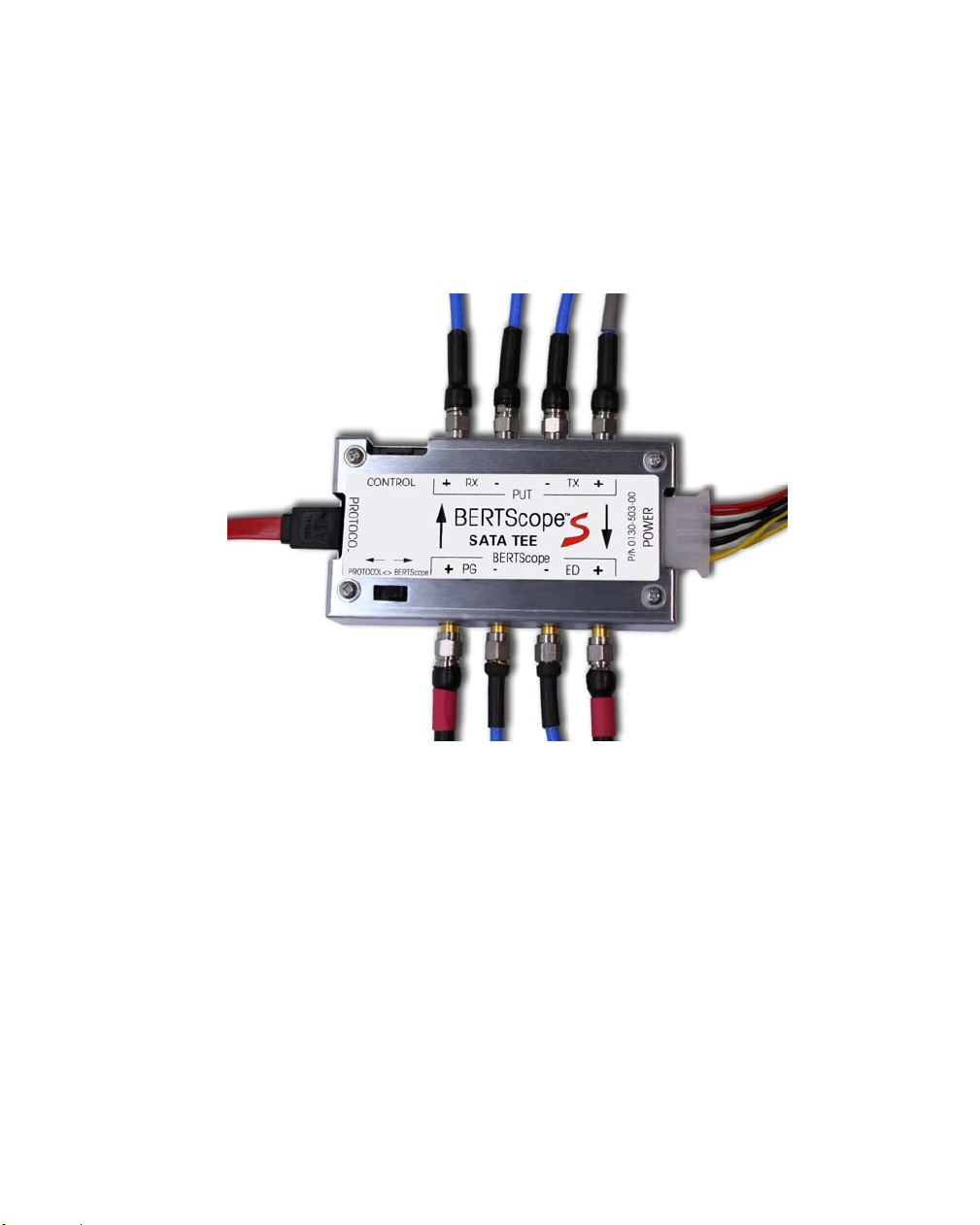
Introduction
The BERTScope SATA Tee facilitates SATA compliance tests by switching the
product under test (PUT) I/O lines between a protocol analyzer and the BERTScope.
This allows the PUT to be set to the proper Built In Self Test (BIST) mode for testing
without disconnecting the SATA connector.
Figure 1. BERTScope SATA Tee
The PUT Transmit (Tx) outputs are split with an asymmetrical splitter which sends a
small fraction of the signal through an amplifier to the protocol Receiver (Rx) inputs.
The majority of the signal is sent to the BERTScope CR inputs. This preserves the
signal to noise ratio of the PUT Tx signal at the BERTScope inputs.
The BERTScope Tx outputs are connected to one side of a symmetrical 6 dB power
combiner. The protocol generator Tx outputs are amplified and connected via a
switch to the other leg of the combiner. The common legs of the combiners are
connected to the PUT Rx inputs. When the switch is set to the “BERTScope”
position, the protocol legs of the combiner are terminated into 50 Ω.
BERTScope™ SATA Tee 0130-710-00.02 23 April 2008 5
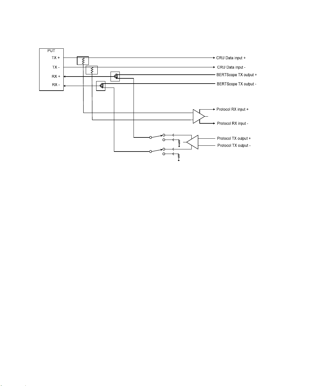
Functional Block Diagram
Figure 2. SATA Tee Functional Block Diagram
Connection
Connect cables to the PUT, BERTScope and Protocol Analyzer as indicated on the
label. Use low loss cables to minimize measurement errors from signal attenuation.
Connect the Power receptacle to an unused IDE hard drive power connector from the
test system PC power supply.
Operation
There are two methods of operation, determined by whether the PUT supports
disconnect:
For PUTs that support disconnect
1. With the BERTScope pattern generator outputs turned off, switch the Tee to
the “Protocol” position.
2. Using the protocol generator, send the desired BIST command to the PUT
and verify a successful transaction.
3. Switch the Tee to the “BERTScope” position and proceed with testing.
6 0130-710-00.02 23 April 2008 BERTScope™ SATA Tee

For PUTs that do not support disconnect
1. With the BERTScope pattern generator outputs off, switch the Tee to the
“Protocol” position.
2. Using the protocol generator, send the desired BIST command to the PUT
and verify a successful transaction.
3. Turn on the BERTScope pattern generator outputs to a voltage level higher
than the protocol generator outputs (e.g. 1000 mV p-p on each leg of the
differential signal). This may require some experimentation to determine the
required voltage depending on the output voltage of the protocol generator.
This step causes the BERTScope PG output signal to be the dominant signal
source, swamping the protocol generator output signal.
4. Switch the Tee to the “BERTScope” position, lower the BERTScope PG
outputs to the proper voltage levels, and proceed with testing.
Remote Control
The state of the SATA Tee switch can also be controlled electrically, enabling its use
with automated or semi-automated testing systems. Remote control is accessible
through the “CONTROL” connector.
The mating connector is a Molex part number 50-57-9406 housing with at least two
contact pins (Molex part number: 16-02-0096). The connection pin-out is as follows:
1 – Control
2 – Ground
3 – +5 V
4 – (not connected)
5 – (not connected)
6 – Ground
Pin 1 is located on the side of the connector near the PUT Rx + connector.
The Control signal switches the SATA Tee from the normal BERTScope testing path
to the Protocol connected path. The signal is pulled up internally to +3.3 volts.
Switching to the Protocol connected path is performed by grounding this pin, either
by shorting to Pin 2 or 6, or with an external open collector or open drain logic gate.
Note that the manual slide switch must be in the BERTScope position to enable
Remote Control operation. Moving the switch to the Protocol position overrides
remote control.
BERTScope™ SATA Tee 0130-710-00.02 23 April 2008 7

Performance Characterization
The BERTScope SATA Tee functionality was verified using a U-Link Drivemaster
protocol analyzer system to ensure that the PUT could be programmed when the
switch was in the “protocol” position. It was then characterized for insertion lo ss and
return loss using a Rohde and Schwarz ZVA-24 Vector Network Analyze r.
Measurements from these tests are shown below:
Figure 3. Insertion Loss PUT TX path
8 0130-710-00.02 23 April 2008 BERTScope™ SATA Tee
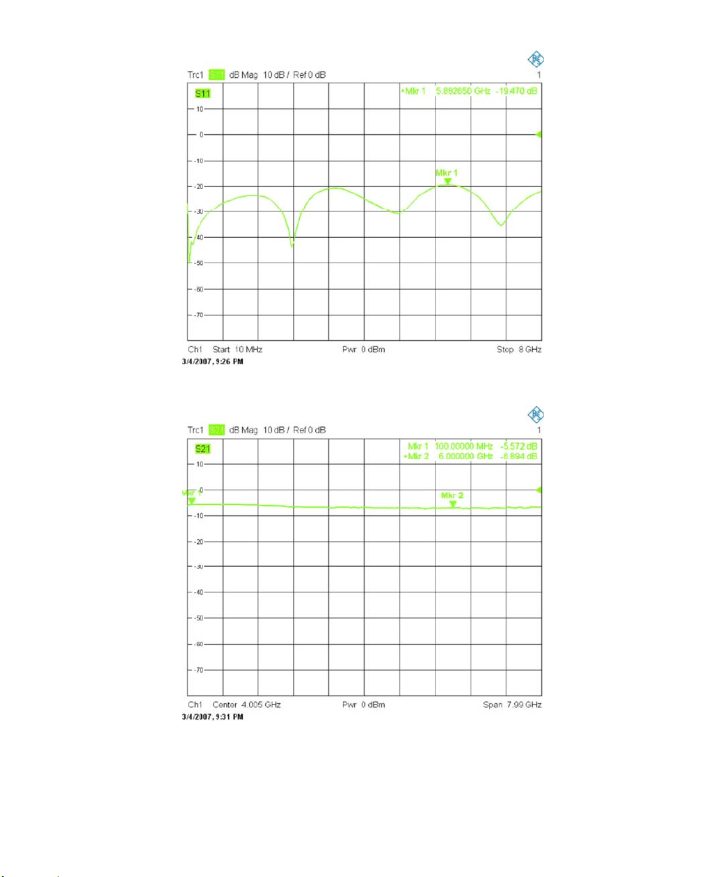
Figure 4. Return Loss PUT TX path
Figure 5. Insertion Loss PUT RX path
BERTScope™ SATA Tee 0130-710-00.02 23 April 2008 9

Figure 6. Return Loss PUT RX path
10 0130-710-00.02 23 April 2008 BERTScope™ SATA Tee
 Loading...