

Page 1

S46L Microwave Switch System
Keithley Instruments, Inc.
28775 Aurora Road
Cleveland, Ohio 44139
1-888-KEITHLEY
(440) 248-0400
www.keithley.com
Relay Installation Guide
Introduction
This guide contains relay installation and system configuration information for the S46L Microwave Switch
System that is necessary after installing new relays. To install a relay , refer to Relay kits
the kits and then follow the applicable installation instructions.
WARNING The information in this section is only intended for qualified service
personnel. Do not attempt to replace p arts or otherwise service the
equipment unless you are qualified to do so.
for a description of
Relay kits
Table 1 summarizes available relay kits and part numbers.
WARNING Use only the part s specified in Table 1 when servicing the equipment.
Use of improper part s may expose the operator to hazardous volt ages
that could result in personal injury or death.
Table 1: S46L relay kits
Relay kit
model number
S46L-SPDT-KIT-L 20 GHz SPDT 1 to 4
S46L-SP6T-KIT-T 18 GHz SP6T A to D
Description
Relay
location
Kit parts summary
(quantity)
SPDT terminated relay
(1)
Connecting cable (1) S46-350
4-40 ×1/4 PPHSEM
screws (2)
4-40 ×3/8 PFH screws
(4)
SP6T terminated relay
(1)
Ribbon cable (1) CA-566B
Keithley
part number
RL-360
4-40X1/4PPHSEM
4-40x3/8PFH
RL-259
Installation
reference
SPDT relay 1
through 4
installation on
page 2
Relays A
through D
installation on
page 4
Installation
Before installing the relays, remove the screws that secure the S46L top cover, and then remove the cover.
PA-1031 Rev. A / March 2011 1
Page 2

S46L Microwave Switch System Relay Installation Guide
Terminated
SPDT relay installation
Relay spacer screws
(2 per relay column)
Terminated
SPDT relay
1
2
3
WARNING Disconnect the power cord and all cables from the S46L before
removing the top cover.
To find the applicable installation procedure for your specific kit, refer to the “Inst allation refere nce” column
in Table 1, and then perform the referenced installation.
SPDT relay 1 through 4 installation
1. Remove the two (2) screws holding relay spacers in the relay column containing the desired relay
installation location (see Figure 1).
Figure 1: SPDT 1 through 4 relay installation
2 PA-1031 Rev. A / March 2011
2. Replace the spacer with the relay in the desired location (refer to the inset in Figure 1 labeled
“Terminated SPDT relay installation”).
3. Install the two (2) screws removed in step 1 in the new relay column.
4. Thread the red and black wires (fro m the relay) thro ugh the PVC tubing ( PVC tubin g, part number
TX-52-7, is part of S46L-350) (not shown). The PVC tubing may be cut to a length that will allow
the relay assembly to be removed without removing the top cover.
5. Referring to Figure 2, solder the three (3) control wires to the terminals of the relay:
NOTE The relay is assembled with it s label facing up, and therefore, the pins shown in
the figure below are on the lower row.
• Solder the red wire to the pin marked +VCC.
• Solder the black wire to the pin marked E1.
• Solder the white wire to the pin marked E2.
Page 3

S46L Microwave Switch System Relay Installation Guide
Red wire
Black wire
(+VCC)(E1)
123
Terminated
SPDT relay
White wire
(E2)
Relay 1-4
connectors
(J18-J21)
Relay A-D
connectors
(J5-J8)
RB
J6
RC
J7
RD
J8
R1
J18
RD
J25
To power
supply board
RA
J5
Relay
1
2
3
4
Connector
J18
J19
J20
J21
Relay
A
B
C
D
Connector
J5, J22
J6. J23
J7, J24
J8, J25
R4
J21
RA
J22
Relay A-D
connectors
(J22-J25)
Figure 2: Connecting control wires to SPDT relay
6. Install the relay mounting bracket using the screws removed in step 1.
7. Plug the wire connector into the appropriate circuit board connector (see Figure 3).
8. Install the top cover, and then configure the system as described in System configuration
Figure 3: Relay connector locations
.
PA-1031 Rev. A / March 2011 3
Page 4

S46L Microwave Switch System Relay Installation Guide
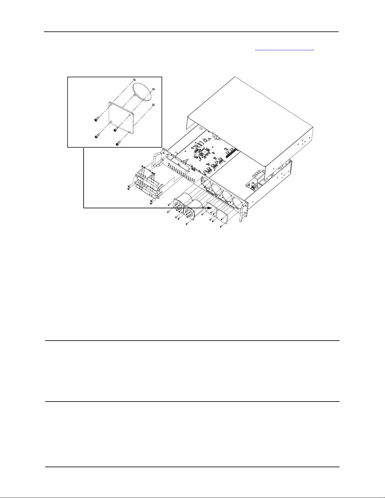
Cover plate
Relays A through D installation
1. Remove the four (4) screws securing the cover plate over the mounting hole where the new relay
will be installed (see Figure 4).
Figure 4: Remove mounting hole cover plate
2. Assemble the supplied ribbon cable to the relay (use Figure 5 as a guide):
Figure 5: Connecting control wires to relays A through D
3. Install the relay in the mounting h ole, and th en secure it with the four ( 4) screws removed in step 1.
4. Plug the ribbon connector into the appropriate circuit board connector (see Figure 3).
4 PA-1031 Rev. A / March 2011
Page 5
S46L Microwave Switch System Relay Installation Guide
Cover plate
5. Install the top cover, and then configure the system as described in System configuration
Figure 6: A through D relay installation
.
System configuration
After installing the new relays, you must program the S46L for the new relay configuration using the following
command:
:ROUT:CONF:CPOL <clist>
Where <clist> is defined as:
clist = (@0 | 3-6, 0 | 3-6, 0 | 3-6, 0 | 3-6, 0 | 1, ... 0 | 1)
Relay: A B C D 1 ... 4
NOTE All switch locations must be included in the <clist> parameter whether or not all
locations are populated. The numeric value (1 or 3-6) indicates the number of
throws; a value of 0 indicates that a location is not populated.
For example, if RELAY A and RELAY B are SP6T, RELAY 1 and RELAY 2 are
SPDTs, and all other locations are not populated, the command syntax is:
:ROUT:CONF:CPOL (@6,6,0,0,1,1,0,0)
See Section 3 of the S46/S46T/S46L Instruction Manual for detailed programming information.
PA-1031 Rev. A / March 2011 5
 Loading...